when you need repair service, call your nearest roland ...ronny/drum/spd20.pdf · jordan amman...
TRANSCRIPT
01453923 '02-2-AE2-61N
OWNER’S MANUAL
Thank you, and congratulations on your choice of the SPD-20Total Percussion Pad. The SPD-20 is an electronic percussion unitthat has eight pads, trigger interfaces, a high-quality digital soundgenerator, and on-board digital effects.
Since the SPD-20 includes a sound generator and effects in onelightweight, compact package, you can use it anywhere, anytime.A wide variety of options (pads, pedals, drum stand, etc.) areavailable, allowing you to easily create a custom drum kit. Byadding sequencers or samplers, you can take advantage of thepossibilities of MIDI percussion.
The SPD-20 provides the flexibility and expandability that will beappreciated by every percussionist, from beginner to professional.
About the Symbols in This ManualWords or symbols enclosed in [square brackets] indicate panelbuttons or controls.For example, [LAYER] signifies the Layer button.
Items marked by are supplementary explanations.
Items headed by explain important points concerning theoperation of your SPD-20.
Items preceded by give you useful tips and informationregarding the use of the SPD-20.
MEMO
NOTE
Before using this unit, carefully read the sections enti-tled: “USING THE UNIT SAFELY” and “IMPORTANTNOTES” (Owner’s manual p. 2; p. 6). These sections pro-vide important information concerning the proper operation ofthe unit. Additionally, in order to feel assured that you havegained a good grasp of every feature provided by your newunit, Owner‘s manual should be read in its entirety. The man-ual should be saved and kept on hand as a convenient refer-ence.
Copyright 1998 ROLAND CORPORATIONAll rights reserved. No part of this publication may be reproduced in anyform without the written permission of ROLAND CORPORATION.
OW
NER
’S MA
NU
AL
InformationWhen you need repair service, call your nearest Roland Service Center or authorized Roland distributor in your country as shown below.
As of January 1, 2002 (Roland)
ARGENTINAInstrumentos Musicales S.A.Av.Santa Fe 2055 (1123) Buenos AiresARGENTINATEL: (011) 4508-2700 BRAZILRoland Brasil LtdaRua San Jose, 780 Sala BParque Industrial San JoseCotia - Sao Paulo - SP, BRAZILTEL: (011) 4615 5666
CANADA Roland Canada Music Ltd.(Head Office)5480 Parkwood Way Richmond B. C., V6V 2M4 CANADA TEL: (0604) 270 6626
Roland Canada Music Ltd.(Toronto Office)Unit 2, 109 Woodbine Downs Blvd, Etobicoke, ONM9W 6Y1 CANADA TEL: (0416) 213 9707
MEXICOCasa Veerkamp, s.a. de c.v.Av. Toluca No. 323, Col. Olivar de los Padres 01780 Mexico D.F. MEXICOTEL: 668-0480
PANAMASUPRO MUNDIAL, S.A.Boulevard Andrews, Albrook, Panama City, REP. DE PANAMATEL: 315-0101
U. S. A. Roland Corporation U.S.5100 S. Eastern AvenueLos Angeles, CA 90040-2938,U. S. A.TEL: (323) 890 3700
VENEZUELAMusicland Digital C.A.Av. Francisco de Miranda,Centro Parque de Cristal, Nivel C2 Local 20 CaracasVENEZUELATEL: (212) 285-8586
AUSTRALIA Roland Corporation Australia Pty., Ltd. 38 Campbell Avenue Dee Why West. NSW 2099 AUSTRALIA TEL: (02) 9982 8266 NEW ZEALAND Roland Corporation Ltd.32 Shaddock Street, Mount Eden, Auckland, NEW ZEALAND TEL: (09) 3098 715
HONG KONGTom Lee Music Co., Ltd. Service Division22-32 Pun Shan Street, Tsuen Wan, New Territories, HONG KONGTEL: 2415 0911
CHINABeijing Xinghai Musical Instruments Co., Ltd.6 Huangmuchang Chao Yang District, Beijing, CHINATEL: (010) 6774 7491
Shanghai Xingtong Acoustics Equipment CO.,Ltd.5F. No.1500 Pingliang Road New East Club Plaza, Shanghai, CHINATEL: (021) 5580-0800
INDIARivera Digitec (India) Pvt. Ltd.409, Nirman Kendra Mahalaxmi Flats Compound Off. Dr. Edwin Moses Road, Mumbai-400011, INDIATEL: (022) 498 3079 INDONESIAPT Citra IntiRamaJ1. Cideng Timur No. 15J-150 Jakarta PusatINDONESIATEL: (021) 6324170
MALAYSIABENTLEY MUSIC SDN BHD140 & 142, Jalan Bukit Bintang 55100 Kuala Lumpur,MALAYSIATEL: (03) 2144-3333
PHILIPPINESG.A. Yupangco & Co. Inc.339 Gil J. Puyat AvenueMakati, Metro Manila 1200,PHILIPPINESTEL: (02) 899 9801
SINGAPORESwee Lee Company150 Sims Drive,SINGAPORE 387381TEL: 846-3676
TAIWANROLAND TAIWAN ENTERPRISE CO., LTD.Room 5, 9fl. No. 112 Chung Shan N.Road Sec.2, Taipei, TAIWAN, R.O.C.TEL: (02) 2561 3339 THAILANDTheera Music Co. , Ltd.330 Verng NakornKasem, Soi 2, Bangkok 10100, THAILANDTEL: (02) 2248821
BAHRAINMoon StoresNo.16, Bab Al Bahrain Avenue, P.O.Box 247, Manama 304, State of BAHRAINTEL: 211 005
VIETNAMSaigon Music138 Tran Quang Khai St., District 1Ho Chi Minh CityVIETNAMTEL: (08) 844-4068
JORDANAMMAN Trading Agency 245 Prince Mohammad St., Amman 1118, JORDANTEL: (06) 464-1200
KUWAITEasa Husain Al-YousifiAbdullah Salem Street,Safat, KUWAITTEL: 243-6399 LEBANONA. Chahine & FilsGerge Zeidan St., Chahine Bldg., Achrafieh, P.O.Box: 16-5857Beirut, LEBANONTEL: (01) 20-1441
QATARAl Emadi Co. (Badie Studio & Stores)P.O. Box 62, Doha, QATARTEL: 4423-554 SAUDI ARABIAaDawliah Universal Electronics APLCorniche Road, Aldossary Bldg., 1st Floor, Alkhobar,SAUDI ARABIA
P.O.Box 2154, Alkhobar 31952SAUDI ARABIA TEL: (03) 898 2081 SYRIATechnical Light & Sound CenterBldg. No. 47, Khaled Ebn Al Walid St.Damascus, SYRIATEL: (011) 221-1230
TURKEY Barkat muzik aletleri ithalat ve ihracat Ltd StiSiraselviler Caddesi Siraselviler Pasaji No:74/20 Taksim - Istanbul, TURKEYTEL: (0212) 2499324 U.A.E.Zak Electronics & Musical Instruments Co. L.L.C.Zabeel Road, Al Sherooq Bldg., No. 14, Grand Floor, Dubai, U.A.E.TEL: (04) 3360715
EGYPTAl Fanny Trading Office9, EBN Hagar A1 Askalany Street,ARD E1 Golf, Heliopolis, Cairo 11341, EGYPTTEL: 20-2-417-1828 REUNIONMaison FO - YAM Marcel25 Rue Jules Hermann,Chaudron - BP79 97 491Ste Clotilde Cedex,REUNION ISLANDTEL: (0262) 218-429
SOUTH AFRICAThat Other Music Shop (PTY) Ltd.11 Melle St., Braamfontein, Johannesbourg, SOUTH AFRICA
P.O.Box 32918, Braamfontein 2017 Johannesbourg, SOUTH AFRICATEL: (011) 403 4105
Paul Bothner (PTY) Ltd.17 Werdmuller Centre, Main Road, Claremont 7708SOUTH AFRICA
P.O.BOX 23032, Claremont 7735, SOUTH AFRICATEL: (021) 674 4030
CYPRUSRadex Sound Equipment Ltd.17, Diagorou Street, Nicosia, CYPRUSTEL: (02) 66-9426
DENMARK Roland Scandinavia A/SNordhavnsvej 7, Postbox 880,DK-2100 CopenhagenDENMARK TEL: (039)16 6200 FRANCERoland France SA4, Rue Paul Henri SPAAK, Parc de l'Esplanade, F 77 462 St. Thibault, Lagny Cedex FRANCETEL: 01 600 73 500 FINLANDRoland Scandinavia As, Filial FinlandLauttasaarentie 54 BFin-00201 Helsinki, FINLANDTEL: (9) 682 4020 GERMANY Roland Elektronische Musikinstrumente HmbH.Oststrasse 96, 22844 Norderstedt, GERMANY TEL: (040) 52 60090
GREECESTOLLAS S.A.Music Sound Light155, New National RoadPatras 26442, GREECETEL: (061) 43-5400 HUNGARYIntermusica Ltd.Warehouse Area ‘DEPO’ Pf.83H-2046 Torokbalint, HUNGARYTEL: (23) 511011 IRELANDRoland IrelandAudio House, Belmont Court,Donnybrook, Dublin 4.Republic of IRELANDTEL: (01) 2603501
ITALYRoland Italy S. p. A. Viale delle Industrie 8, 20020 Arese, Milano, ITALYTEL: (02) 937-78300 NORWAYRoland Scandinavia Avd. Kontor NorgeLilleakerveien 2 Postboks 95 Lilleaker N-0216 Oslo NORWAYTEL: 273 0074 POLANDP. P. H. BrzostowiczUL. Gibraltarska 4.PL-03664 Warszawa POLANDTEL: (022) 679 44 19 PORTUGALTecnologias Musica e Audio, Roland Portugal, S.A.Cais Das Pedras, 8/9-1 Dto4050-465 PORTOPORTUGALTEL: (022) 608 00 60
RUSSIAMuTek3-Bogatyrskaya Str. 1.k.l107 564 Moscow, RUSSIA TEL: (095) 169 5043
SPAINRoland Electronics de España, S. A. Calle Bolivia 239, 08020 Barcelona, SPAINTEL: (93) 308 1000
SWITZERLANDRoland (Switzerland) AGMusitronic AG Gerberstrasse 5, Postfach,CH-4410 Liestal, SWITZERLANDTEL: (061) 927-8383
SWEDEN Roland Scandinavia A/S SWEDISH SALES OFFICEDanvik Center 28, 2 tr. S-131 30 Nacka SWEDEN TEL: (08) 702 0020
UKRAINETIC-TACMira Str. 19/108P.O. Box 180 295400 Munkachevo, UKRAINETEL: (03131) 414-40 UNITED KINGDOM Roland (U.K.) Ltd.Atlantic Close, Swansea Enterprise Park, SWANSEASA7 9FJ, UNITED KINGDOMTEL: (01792) 700139
KOREACosmos Corporation1461-9, Seocho-Dong,Seocho Ku, Seoul, KOREATEL: (02) 3486-8855
AUSTRIARoland Austria GES.M.B.H.Siemensstrasse 4, P.O. Box 74,A-6063 RUM, AUSTRIATEL: (0512) 26 44 260 BELGIUM/HOLLAND/LUXEMBOURGRoland Benelux N. V.Houtstraat 3, B-2260, Oevel (Westerlo) BELGIUMTEL: (014) 575811
AFRICA
CHILEComercial Fancy S.A.Rut.: 96.919.420-1Nataniel Cox #739, 4th FloorSantiago - Centro, CHILETEL: (02) 688-9540
URUGUAYTodo Musica S.A.Francisco Acuna de Figueroa 1771C.P.: 11.800 Montevideo, URUGUAYTEL: (02) 924-2335
EUROPEAUSTRALIA/NEW ZEALAND
ASIA
CENTRAL/LATINAMERICA
NORTH AMERICA
MIDDLE EAST
AFRICA
EL SALVADOROMNI MUSIC75 Avenida Norte y Final Alameda Juan Pablo , Edificio No.4010 San Salvador, EL SALVADORTEL: 262-0788
ROMANIAFBS LINESPiata Libertatii 1,RO-4200 GheorghehiTEL: (095) 169-5043
PARAGUAYDistribuidora De Instrumentos MusicalesJ.E. Olear y ESQ. Manduvira Asuncion PARAGUAYTEL: (021) 492-124 PERUVIDEO Broadcast S.A.Portinari 199 (ESQ. HALS), San Borja, Lima 41,REP. OF PERUTEL: (01) 4758226
COSTA RICAJUAN Bansbach Instrumentos MusicalesAve.1. Calle 11, Apartado 10237,San Jose, COSTA RICATEL: 258-0211
CRISTOFORI MUSIC PTE LTDBlk 3014, Bedok Industrial Park E, #02-2148, SINGAPORE 489980TEL: 243 9555
IRANMOCO, INC.No.41 Nike St., Dr.Shariyati Ave.,Roberoye Cerahe MirdamadTehran, IRANTEL: (021) 285-4169
ISRAELHalilit P. Greenspoon & Sons Ltd.8 Retzif Ha'aliya Hashnya St.Tel-Aviv-Yafo ISRAELTEL: (03) 6823666
2
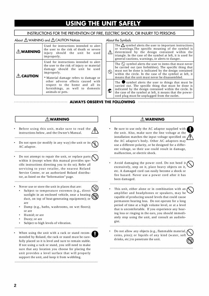
Used for instructions intended to alert the user to the risk of injury or material damage should the unit be used improperly.
* Material damage refers to damage or other adverse effects caused with respect to the home and all its furnishings, as well to domestic animals or pets.
Used for instructions intended to alert the user to the risk of death or severe injury should the unit be used improperly.
The ● symbol alerts the user to things that must be carried out. The specific thing that must be done is indicated by the design contained within the circle. In the case of the symbol at left, it means that the power-cord plug must be unplugged from the outlet.
The symbol alerts the user to important instructions or warnings.The specific meaning of the symbol is determined by the design contained within the triangle. In the case of the symbol at left, it is used for general cautions, warnings, or alerts to danger.
The symbol alerts the user to items that must never be carried out (are forbidden). The specific thing that must not be done is indicated by the design contained within the circle. In the case of the symbol at left, it means that the unit must never be disassembled.
• Before using this unit, make sure to read theinstructions below, and the Owner's Manual.
.........................................................................................................
• Do not open (or modify in any way) the unit or itsAC adaptor.
.........................................................................................................
• Do not attempt to repair the unit, or replace partswithin it (except when this manual provides spe-cific instructions directing you to do so). Refer allservicing to your retailer, the nearest RolandService Center, or an authorized Roland distribu-tor, as listed on the "Information" page.
.........................................................................................................
• Never use or store the unit in places that are:• Subject to temperature extremes (e.g., direct
sunlight in an enclosed vehicle, near a heatingduct, on top of heat-generating equipment); orare
• Damp (e.g., baths, washrooms, on wet floors);or are
• Humid; or are• Dusty; or are• Subject to high levels of vibration.
.........................................................................................................
• When using the unit with a rack or stand recom-mended by Roland, the rack or stand must be care-fully placed so it is level and sure to remain stable.If not using a rack or stand, you still need to makesure that any location you choose for placing theunit provides a level surface that will properlysupport the unit, and keep it from wobbling.
.........................................................................................................
• Be sure to use only the AC adaptor supplied withthe unit. Also, make sure the line voltage at theinstallation matches the input voltage specified onthe AC adaptor's body. Other AC adaptors mayuse a different polarity, or be designed for a differ-ent voltage, so their use could result in damage,malfunction, or electric shock.
.........................................................................................................
• Avoid damaging the power cord. Do not bend itexcessively, step on it, place heavy objects on it,etc. A damaged cord can easily become a shock orfire hazard. Never use a power cord after it hasbeen damaged.
.........................................................................................................
• This unit, either alone or in combination with anamplifier and headphones or speakers, may becapable of producing sound levels that could causepermanent hearing loss. Do not operate for a longperiod of time at a high volume level, or at a levelthat is uncomfortable. If you experience any hear-ing loss or ringing in the ears, you should immedi-ately stop using the unit, and consult an audiolo-gist.
.........................................................................................................
• Do not allow any objects (e.g., flammable material,coins, pins); or liquids of any kind (water, softdrinks, etc.) to penetrate the unit.
.........................................................................................................
For the USA
FEDERAL COMMUNICATIONS COMMISSIONRADIO FREQUENCY INTERFERENCE STATEMENT
This equipment has been tested and found to comply with the limits for a Class B digital device, pursuant to Part 15 of the FCC Rules. These limits are designed to provide reasonable protection against harmful interference in a residential installation. This equipment generates, uses, and can radiate radio frequency energy and, if not installed and used in accordance with the instructions, may cause harmful interference to radio communications. However, there is no guarantee that interference will not occur in a particular installation. If this equipment does cause harmful interference to radio or television reception, which can be determined by turning the equipment off and on, the user is encouraged to try to correct the interference by one or more of the following measures:
– Reorient or relocate the receiving antenna.– Increase the separation between the equipment and receiver.– Connect the equipment into an outlet on a circuit different from that to which the receiver is connected.– Consult the dealer or an experienced radio/TV technician for help.
Unauthorized changes or modification to this system can void the users authority to operate this equipment.This equipment requires shielded interface cables in order to meet FCC class B Limit.
IMPORTANT: THE WIRES IN THIS MAINS LEAD ARE COLOURED IN ACCORDANCE WITH THE FOLLOWING CODE.
BLUE: BROWN:
As the colours of the wires in the mains lead of this apparatus may not correspond with the coloured markings identifying the terminals in your plug, proceed as follows:The wire which is coloured BLUE must be connected to the terminal which is marked with the letter N or coloured BLACK.The wire which is coloured BROWN must be connected to the terminal which is marked with the letter L or coloured RED.Under no circumstances must either of the above wires be connected to the earth terminal of a three pin plug.
NEUTRALLIVE
For the U.K.
This product complies with the requirements of European Directive 89/336/EEC.
For EU Countries
For EU Countries
Apparatus containing Lithium batteries
ADVARSEL!Lithiumbatteri - Eksplosionsfare ved fejlagtig håndtering.Udskiftning må kun ske med batteri afsamme fabrikat og type.Levér det brugte batteri tilbage til leverandøren.
VARNINGExplosionsfara vid felaktigt batteribyte.Använd samma batterityp eller en ekvivalent typ som rekommenderas av apparattillverkaren.Kassera använt batteri enligt fabrikantens instruktion.
CAUTIONDanger of explosion if battery is incorrectly replaced.Replace only with the same or equivalent type recommended by the manufacturer.Discard used batteries according to the manufacturer’s instructions.
ADVARSELEksplosjonsfare ved feilaktig skifte av batteri.Benytt samme batteritype eller en tilsvarende type anbefalt av apparatfabrikanten.Brukte batterier kasseres i henhold til fabrikantens instruks joner.
VAROITUSParisto voi räjähtää, jos se onvirheellisesti asennettu.Vaihda paristo ainoastaan laitevalmistajan suosittelemaan tyyppiin. Hävitä käytetty paristo valmistajan ohjeiden mukaisesti.
For Canada
This Class B digital apparatus meets all requirements of the Canadian Interference-Causing Equipment Regulations.
Cet appareil numérique de la classe B respecte toutes les exigences du Règlement sur le matériel brouilleur du Canada.
NOTICE
AVIS
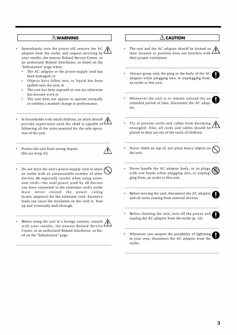
• Immediately turn the power off, remove the ACadaptor from the outlet, and request servicing byyour retailer, the nearest Roland Service Center, oran authorized Roland distributor, as listed on the"Information" page when:• The AC adaptor or the power-supply cord has
been damaged; or• Objects have fallen into, or liquid has been
spilled onto the unit; or• The unit has been exposed to rain (or otherwise
has become wet); or• The unit does not appear to operate normally
or exhibits a marked change in performance.
.........................................................................................................
• In households with small children, an adult shouldprovide supervision until the child is capable offollowing all the rules essential for the safe opera-tion of the unit.
.........................................................................................................
• Protect the unit from strong impact.(Do not drop it!)
.........................................................................................................
• Do not force the unit's power-supply cord to sharean outlet with an unreasonable number of otherdevices. Be especially careful when using exten-sion cords—the total power used by all devicesyou have connected to the extension cord's outletmust never exceed the power rating(watts/amperes) for the extension cord. Excessiveloads can cause the insulation on the cord to heatup and eventually melt through.
.........................................................................................................
• Before using the unit in a foreign country, consultwith your retailer, the nearest Roland ServiceCenter, or an authorized Roland distributor, as list-ed on the "Information" page.
.........................................................................................................
• The unit and the AC adaptor should be located sotheir location or position does not interfere withtheir proper ventilation.
.........................................................................................................
• Always grasp only the plug or the body of the ACadaptor when plugging into, or unplugging from,an outlet or this unit.
.........................................................................................................
• Whenever the unit is to remain unused for anextended period of time, disconnect the AC adap-tor.
.........................................................................................................
• Try to prevent cords and cables from becomingentangled. Also, all cords and cables should beplaced so they are out of the reach of children.
.........................................................................................................
• Never climb on top of, nor place heavy objects onthe unit.
.........................................................................................................
• Never handle the AC adaptor body, or its plugs,with wet hands when plugging into, or unplug-ging from, an outlet or this unit.
.........................................................................................................
• Before moving the unit, disconnect the AC adaptorand all cords coming from external devices.
.........................................................................................................
• Before cleaning the unit, turn off the power andunplug the AC adaptor from the outlet (p. 12).
.........................................................................................................
• Whenever you suspect the possibility of lightningin your area, disconnect the AC adaptor from theoutlet.
.........................................................................................................
3
1
2
3
4
5
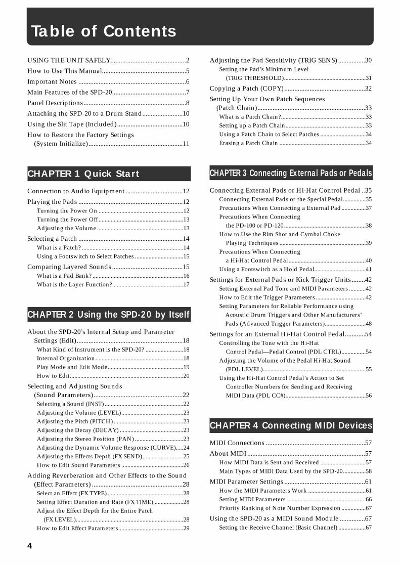
USING THE UNIT SAFELY.............................................2
How to Use This Manual..................................................5
Important Notes ................................................................6
Main Features of the SPD-20............................................7
Panel Descriptions.............................................................8
Attaching the SPD-20 to a Drum Stand........................10
Using the Slit Tape (Included).......................................10
How to Restore the Factory Settings(System Initialize) ........................................................11
CHAPTER 1 Quick Start
Connection to Audio Equipment ..................................12
Playing the Pads ..............................................................12Turning the Power On ........................................................12Turning the Power Off ........................................................13Adjusting the Volume .........................................................13
Selecting a Patch ..............................................................14What is a Patch? ...................................................................14Using a Footswitch to Select Patches ................................15
Comparing Layered Sounds..........................................15What is a Pad Bank? ............................................................16What is the Layer Function?...............................................17
CHAPTER 2 Using the SPD-20 by Itself
About the SPD-20’s Internal Setup and ParameterSettings (Edit)...............................................................18What Kind of Instrument is the SPD-20? .........................18Internal Organization..........................................................18Play Mode and Edit Mode..................................................19How to Edit...........................................................................20
Selecting and Adjusting Sounds(Sound Parameters).....................................................22Selecting a Sound (INST) ....................................................22Adjusting the Volume (LEVEL).........................................23Adjusting the Pitch (PITCH) ..............................................23Adjusting the Decay (DECAY) ..........................................23Adjusting the Stereo Position (PAN) ................................23Adjusting the Dynamic Volume Response (CURVE).....24Adjusting the Effects Depth (FX SEND)...........................25How to Edit Sound Parameters .........................................26
Adding Reverberation and Other Effects to the Sound(Effect Parameters) ......................................................28Select an Effect (FX TYPE) ..................................................28Setting Effect Duration and Rate (FX TIME) ...................28Adjust the Effect Depth for the Entire Patch
(FX LEVEL).......................................................................28How to Edit Effect Parameters...........................................29
Adjusting the Pad Sensitivity (TRIG SENS) ................30Setting the Pad’s Minimum Level
(TRIG THRESHOLD)......................................................31
Copying a Patch (COPY) ................................................32
Setting Up Your Own Patch Sequences(Patch Chain)................................................................33What is a Patch Chain?........................................................33Setting up a Patch Chain.....................................................33Using a Patch Chain to Select Patches ..............................34Erasing a Patch Chain .........................................................34
CHAPTER 3 Connecting External Pads or Pedals
Connecting External Pads or Hi-Hat Control Pedal ..35Connecting External Pads or the Special Pedal...............35Precautions When Connecting a External Pad................37Precautions When Connecting
the PD-100 or PD-120......................................................38How to Use the Rim Shot and Cymbal Choke
Playing Techniques .........................................................39Precautions When Connecting
a Hi-Hat Control Pedal...................................................40Using a Footswitch as a Hold Pedal..................................41
Settings for External Pads or Kick Trigger Units........42Setting External Pad Tone and MIDI Parameters ...........42How to Edit the Trigger Parameters .................................42Setting Parameters for Reliable Performance using
Acoustic Drum Triggers and Other Manufacturers’ Pads (Advanced Trigger Parameters)...........................48
Settings for an External Hi-Hat Control Pedal............54Controlling the Tone with the Hi-Hat
Control Pedal—Pedal Control (PDL CTRL)................54Adjusting the Volume of the Pedal Hi-Hat Sound
(PDL LEVEL)....................................................................55Using the Hi-Hat Control Pedal’s Action to Set
Controller Numbers for Sending and ReceivingMIDI Data (PDL CC#).....................................................56
CHAPTER 4 Connecting MIDI Devices
MIDI Connections ...........................................................57
About MIDI ......................................................................57How MIDI Data is Sent and Received ..............................57Main Types of MIDI Data Used by the SPD-20...............58
MIDI Parameter Settings ................................................61How the MIDI Parameters Work ......................................61Setting MIDI Parameters ....................................................66Priority Ranking of Note Number Expression ................67
Using the SPD-20 as a MIDI Sound Module ...............67Setting the Receive Channel (Basic Channel) ..................67
Table of Contents
4
Settings for Each Pad...........................................................68Using External MIDI Devices to Play the Internal
Sound Generator..............................................................69Expanding Patches to Allow Reception of Many
Note Numbers (Patch Expand) .....................................69
How to Use a Sequencer or a Computer toRecord/Play back Your Performance ......................72Connecting a Computer (or a Sequencer) ........................72Breaking/Cutting the Connection Between the Sound
Generator and the Pad Controller (Local Control).....72How to Set Up the SPD-20 for Sequencing ......................74Storing the SPD-20’s Data in External Devices
(Bulk Dump) ....................................................................75How to Transmit (Bulk Dump)..........................................75How to Receive (Bulk Load) ..............................................76Reading SPD-11 Data with the SPD-20.............................77What is Device ID ................................................................78
CHAPTER 5 Supplementary Materials
Taking Advantage of the On-board Effects.................79
Troubleshooting...............................................................82
Error Messages.................................................................87
Instrument List.................................................................88
Patch List ..........................................................................93
Parameter List ..................................................................94Trigger Type Internal Parameters(Advanced Trigger Parameters) ........................................94
Blank Parameter Chart ...................................................95
Roland Exclusive Message .............................................96
MIDI Implementation.....................................................98
MIDI Implementation Chart........................................102
How to Read a MIDI Implementation Chart ............103
Specifications..................................................................104
Index................................................................................105
How-To Index ................................................................106
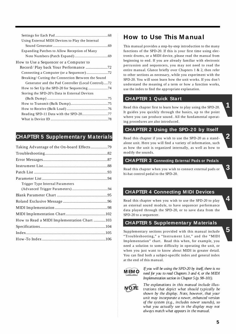
How to Use This ManualThis manual provides a step-by-step introduction to the manyfunctions of the SPD-20. If this is your first time using elec-tronic drums, or a MIDI device, please read the manual frombeginning to end. If you are already familiar with electronicpercussion and sequencers, you may not need to read theentire manual. Glance briefly over Chapters 1 & 2, then referto other sections as necessary, while you experiment with theSPD-20. You will soon learn how the unit works. If you don’tunderstand the meaning of a term or how a function works,use the index to find the appropriate explanation.
CHAPTER 1 Quick Start
Read this chapter first to learn how to play using the SPD-20.It guides you quickly through the basics, up to the pointwhere you can produce sound. All the fundamental operat-ing procedures are also introduced.
CHAPTER 2 Using the SPD-20 by Itself
Read this chapter if you wish to use the SPD-20 as a stand-alone unit. Here you will find a variety of information, suchas how the unit is organized internally, as well as how tomodify the sounds.
CHAPTER 3 Connecting External Pads or Pedals
Read this chapter when you wish to connect external pads orhi-hat control pedal to the SPD-20.
CHAPTER 4 Connecting MIDI Devices
Read this chapter when you wish to use the SPD-20 to playan external sound module, to have sequencer performancedata played through the SPD-20, or to save data from theSPD-20 to a sequencer.
CHAPTER 5 Supplementary Materials
Supplementary sections provided with this manual include“Troubleshooting,” a “Instrument List,” and the “MIDIImplementation” chart. Read this when, for example, youneed a solution to some difficulty in operating the unit, orwhen you just want to know about MIDI in greater detail.You can find both a subject-specific index and general indexat the end of this manual.
If you will be using the SPD-20 by itself, there is noneed for you to read Chapters 3 and 4, or the MIDIImplementation section in Chapter 5 (p. 98–101).
The explanations in this manual include illus-trations that depict what should typically beshown by the display. Note, however, that yourunit may incorporate a newer, enhanced versionof the system (e.g., includes newer sounds), sowhat you actually see in the display may notalways match what appears in the manual.
MEMO
NOTE
5
1
2
3
4
5

In addition to the items listed under “USING THE UNIT SAFELY” on page 2, please read and observe the following:
Important Notes
6
Power Supply• Do not use this unit on the same power circuit with any
device that will generate line noise (such as an electricmotor or variable lighting system).
• The AC adaptor will begin to generate heat after longhours of consecutive use. This is normal, and is not acause for concern.
• Before connecting this unit to other devices, turn off thepower to all units. This will help prevent malfunctionsand/or damage to speakers or other devices.
Placement• Using the unit near power amplifiers (or other equip-
ment containing large power transformers) may inducehum. To alleviate the problem, change the orientation ofthis unit; or move it farther away from the source ofinterference.
• This device may interfere with radio and televisionreception. Do not use this device in the vicinity of suchreceivers.
• Do not expose the unit to direct sunlight, place it neardevices that radiate heat, leave it inside an enclosed vehi-cle, or otherwise subject it to temperature extremes.Excessive heat can deform or discolor the unit.
Maintenance• For everyday cleaning wipe the unit with a soft, dry
cloth or one that has been slightly dampened with water.To remove stubborn dirt, use a cloth impregnated with amild, non-abrasive detergent. Afterwards, be sure towipe the unit thoroughly with a soft, dry cloth.
• Never use benzine, thinners, alcohol or solvents of anykind, to avoid the possibility of discoloration and/ordeformation.
Repairs and Data• Please be aware that all data contained in the unit’s
memory may be lost when the unit is sent for repairs.Important data should always be backed up in anotherMIDI device (e.g., a sequencer), or written down onpaper (when possible). During repairs, due care is takento avoid the loss of data. However, in certain cases (suchas when circuitry related to memory itself is out oforder), we regret that it may not be possible to restore thedata, and Roland assumes no liability concerning suchloss of data.
Memory Backup• This unit contains a battery which powers the unit’s
memory circuits while the main power is off. When thisbattery becomes weak, the message shown below willappear in the display. Once you see this message, havethe battery replaced with a fresh one as soon as possibleto avoid the loss of all data in memory. To have the bat-tery replaced, consult with your retailer, the nearestRoland Service Center, or an authorized Roland distribu-tor, as listed on the “Information” page.
Additional Precautions• Unfortunately, it may be impossible to restore the con-
tents of data that was stored in another MIDI device (e.g.,a sequencer) once it has been lost. Roland Corporationassumes no liability concerning such loss of data.
• Use a reasonable amount of care when using the unit’sbuttons, sliders, or other controls; and when using itsjacks and connectors. Rough handling can lead to mal-functions.
• Never strike or apply strong pressure to the display.
• When connecting/disconnecting all cables, grasp theconnector itself—never pull on the cable. This way youwill avoid causing shorts, or damage to the cable’s inter-nal elements.
• To avoid disturbing your neighbors, try to keep theunit’s volume at reasonable levels. You may prefer to useheadphones, so you do not need to be concerned aboutthose around you (especially when it is late at night).
• This instrument is designed to minimize the extraneoussounds produced when it's played. However, sincesound vibrations can be transmitted through floors andwalls to a greater degree than expected, take care not toallow these sounds to become a nuisance to neighbors,especially when performing at night and when usingheadphones.
• When you need to transport the unit, package it in thebox (including padding) that it came in, if possible.Otherwise, you will need to use equivalent packagingmaterials.

• The SPD-20 features 700 different internal instruments, including drum set sounds, percus-sion sounds from around the world, dance sounds, sound effects, phrase loops, and more,that can be used in a wide variety of musical genres. (Instrument List p. 88)
• Each sound can be edited using a wide variety of sound parameters, including level, pitch,decay, pan, velocity curve, and effect send (p. 22).
• Using the Layer function, different Velocity Curves can be assigned to each of two sounds,and the two sounds mixed (or switched) by your playing dynamics (p. 17).
• The on-board digital effects unit (Reverb, Delay, Chorus and Flanger) allows you to set theeffect depth independently for each sound assigned to a pad (p. 28).
• Four external dual trigger inputs are provided, allowing you to connect kick trigger units(KD-7s; sold separately) or pads (PD-7, PD-9, PD-5, PD-120, PD-100: sold separately), forplaying in conjunction with the SPD-20’s pads (p. 35). When you connect the PD-7 or PD-9,you can enjoy such drum techniques as snare rim shots and cymbal choking (p. 39). With thePD-120 connected, you can play rim shots. What’s more, you can play the SPD-20’s soundsusing an acoustic drum trigger attached to an acoustic drum (p. 45).
• When a hi-hat control pedal (FD-7; sold separately) is connected, you have continuous con-trol (from closed to open) of the hi-hat sounds (p. 54).
• Settings for the SPD-20’s 8 pads, 4 external pads, hi-hat control pedal, and the effects unit canbe stored as one of 99 Patches. This means that a single SPD-20 is able to store and instantlyrecall 99 different percussion “sets,” covering virtually any style of music you can imagine.
• Using the Patch Chain function, you can create and store a sequence of up to 16 Patcheswhich can be selected in a predetermined order (convenient for use within a song). The SPD-20 can store eight such Patch Chains (p. 33).
• For each pad, you can set two independent MIDI transmit channels and Velocity Curves, sothat your playing dynamics can control external and internal sound generators (p. 61).
• The SPD-20 is fully expandable via MIDI, and is especially powerful when used with asequencer. For example, you might record SPD-20 settings as bulk data (p. 75) at the begin-ning of sequencer song data, or allow the sequencer to take care of Patch selection so that youcan concentrate on playing.
Main Features of the SPD-20
7
1
2
3
4
5

Frontfig. (Front Panel)
Rearfig. (Rear Panel and Cord Hook)
Cord Hook
To prevent the disruption of power to your unit (should the plug be pulled out accidentally), and toavoid applying undue stress to the AC adaptor jack, anchor the power cord using the cord hook, asshown in the illustration.
21 3 54
14 1315
6 7 8 9 10 1112
Pad 1 Pad 2 Pad 3 Pad 4
Pad 5 Pad 6 Pad 7 Pad 8
16 17 18 19 20 21 22 23 24 25
NOTE
Panel Descriptions
8
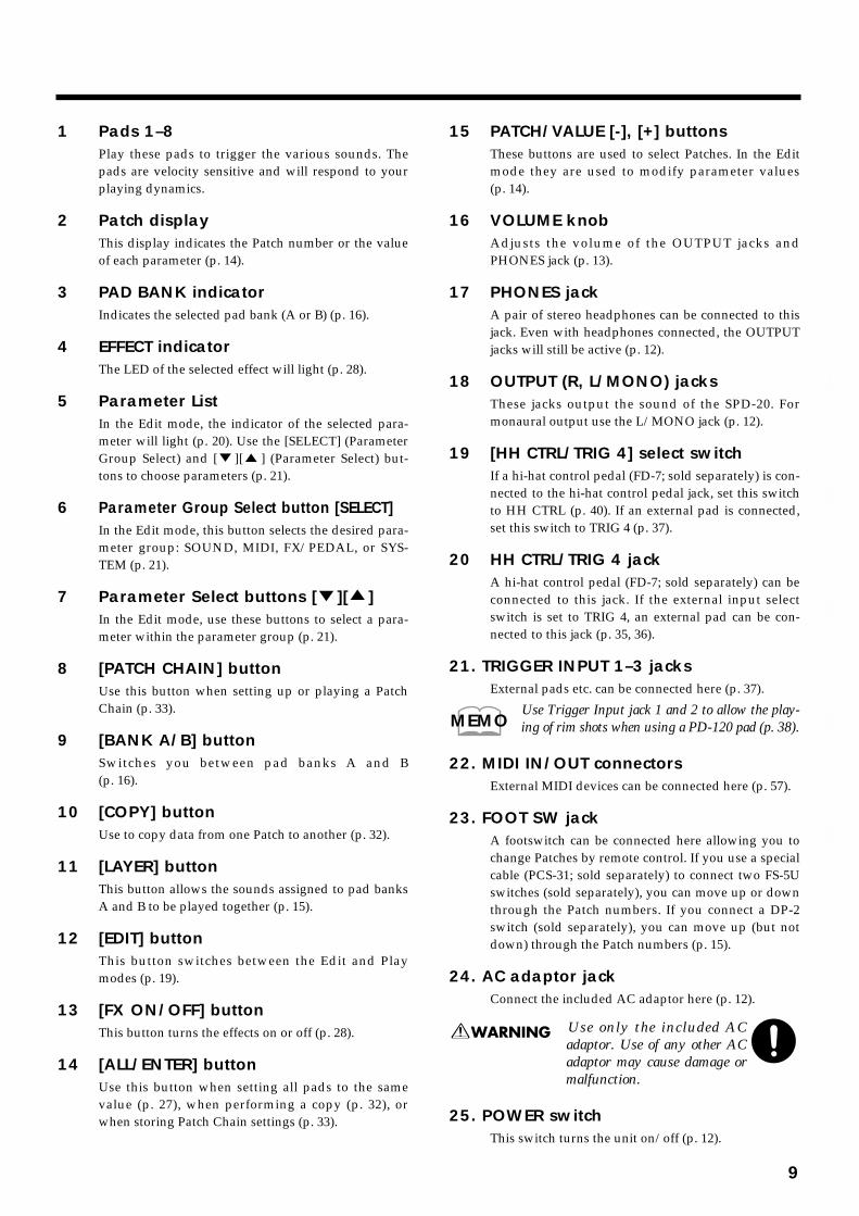
1 Pads 1–8Play these pads to trigger the various sounds. Thepads are velocity sensitive and will respond to yourplaying dynamics.
2 Patch displayThis display indicates the Patch number or the valueof each parameter (p. 14).
3 PAD BANK indicatorIndicates the selected pad bank (A or B) (p. 16).
4 EFFECT indicatorThe LED of the selected effect will light (p. 28).
5 Parameter ListIn the Edit mode, the indicator of the selected para-meter will light (p. 20). Use the [SELECT] (ParameterGroup Select) and [ ][ ] (Parameter Select) but-tons to choose parameters (p. 21).
6 Parameter Group Select button [SELECT]In the Edit mode, this button selects the desired para-meter group: SOUND, MIDI, FX/PEDAL, or SYS-TEM (p. 21).
7 Parameter Select buttons [ ][ ]In the Edit mode, use these buttons to select a para-meter within the parameter group (p. 21).
8 [PATCH CHAIN] buttonUse this button when setting up or playing a PatchChain (p. 33).
9 [BANK A/B] buttonSwitches you between pad banks A and B(p. 16).
10 [COPY] buttonUse to copy data from one Patch to another (p. 32).
11 [LAYER] buttonThis button allows the sounds assigned to pad banksA and B to be played together (p. 15).
12 [EDIT] buttonThis button switches between the Edit and Playmodes (p. 19).
13 [FX ON/OFF] buttonThis button turns the effects on or off (p. 28).
14 [ALL/ENTER] buttonUse this button when setting all pads to the samevalue (p. 27), when performing a copy (p. 32), orwhen storing Patch Chain settings (p. 33).
15 PATCH/VALUE [-], [+] buttonsThese buttons are used to select Patches. In the Editmode they are used to modify parameter values(p. 14).
16 VOLUME knobAdjusts the volume of the OUTPUT jacks andPHONES jack (p. 13).
17 PHONES jackA pair of stereo headphones can be connected to thisjack. Even with headphones connected, the OUTPUTjacks will still be active (p. 12).
18 OUTPUT (R, L/MONO) jacksThese jacks output the sound of the SPD-20. Formonaural output use the L/MONO jack (p. 12).
19 [HH CTRL/TRIG 4] select switchIf a hi-hat control pedal (FD-7; sold separately) is con-nected to the hi-hat control pedal jack, set this switchto HH CTRL (p. 40). If an external pad is connected,set this switch to TRIG 4 (p. 37).
20 HH CTRL/TRIG 4 jackA hi-hat control pedal (FD-7; sold separately) can beconnected to this jack. If the external input selectswitch is set to TRIG 4, an external pad can be con-nected to this jack (p. 35, 36).
21. TRIGGER INPUT 1–3 jacksExternal pads etc. can be connected here (p. 37).
Use Trigger Input jack 1 and 2 to allow the play-ing of rim shots when using a PD-120 pad (p. 38).
22. MIDI IN/OUT connectorsExternal MIDI devices can be connected here (p. 57).
23. FOOT SW jackA footswitch can be connected here allowing you tochange Patches by remote control. If you use a specialcable (PCS-31; sold separately) to connect two FS-5Uswitches (sold separately), you can move up or downthrough the Patch numbers. If you connect a DP-2switch (sold separately), you can move up (but notdown) through the Patch numbers (p. 15).
24. AC adaptor jackConnect the included AC adaptor here (p. 12).
Use only the included ACadaptor. Use of any other ACadaptor may cause damage ormalfunction.
25. POWER switchThis switch turns the unit on/off (p. 12).
MEMO
9
1
2
3
4
5

Attaching the SPD-20 to a Drum StandIf you are attaching the unit to a cymbal stand etc. with a pipe diameter of 10.5–30 mm, use an all pur-pose clamp set (APC-33: sold separately).
1 Using a 4 mm wrench, remove the four screws from the bottom ofthe SPD-20.
fig.3
2 Use the four screws you removed in step 1 to attach the stand hold-er to the bottom of the SPD-20.
fig.4
The screws included with the APC-33 cannot be used.
Using the Slit Tape (Included)Place the Slit tape, included with the SPD-20, along the slits, or grooves around each of the pads. TheSlit tape allows you to clearly distinguish where each pad is, even on stage or in other darkened loca-tions.
fig. Slit Tape
Please note that Roland does not handle replacements or additional purchases of Slit Tape.
NOTE
54
321
NOTE
10
How to Restore the Factory Settings (System Initialize)When the SPD-20 is shipped, it contains 99 Patches in memory. You can freely overwrite this data.However, the same data is also preserved in ROM, and can be restored at any time. This procedure iscalled System Initialize.
The explanations in this manual assume that the SPD-20 is still in its factory initialized state. We recom-mend that before you begin using the unit, you perform this System Initialize operation.
When you execute the System Initialize operation, all your edited data will be lost. If your SPD-20contains important edited data, you should make a note of the settings or store the data in an externaldevice such as a sequencer (p. 75).
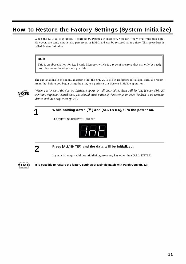
1 While holding down [ ] and [ALL/ENTER], turn the power on.
The following display will appear.fig.5
2 Press [ALL/ENTER] and the data will be initialized.
If you wish to quit without initializing, press any key other than [ALL/ENTER].
It is possible to restore the factory settings of a single patch with Patch Copy (p. 32).
ROM
This is an abbreviation for Read Only Memory, which is a type of memory that can only be read;modification or deletion is not possible.
NOTE
MEMO
11
1
2
3
4
5

Connection to Audio EquipmentWith the SPD-20, you can produce realistic sounds simply by connecting an audio system. You can alsouse headphones.
fig.6
To prevent malfunction and/or damage to speakers or other devices, always turn down the volume,and turn off the power on all devices before making any connections.
Playing the PadsWhen connections are complete, you can play the SPD-20.
Turning the Power OnThe POWER switch is on the rear panel.
Once the connections have been completed, turn on power to your various devices in the order speci-fied. By turning on devices in the wrong order, you risk causing malfunction and/or damage to speak-ers and other devices.
Always make sure to have the volume level turned down before switching on power. Even with thevolume all the way down, you may still hear some sound when the power is switched on, but this isnormal, and does not indicate a malfunction.
1 Check that all connections with other devices are correct, and thateverything is off.
L I N E I NL R
AC adaptor
Audio Equipment(Stereo set)
Footswitches
Stereo Headphones
NOTE
NOTE
CHAPTER 1 Quick Start
12
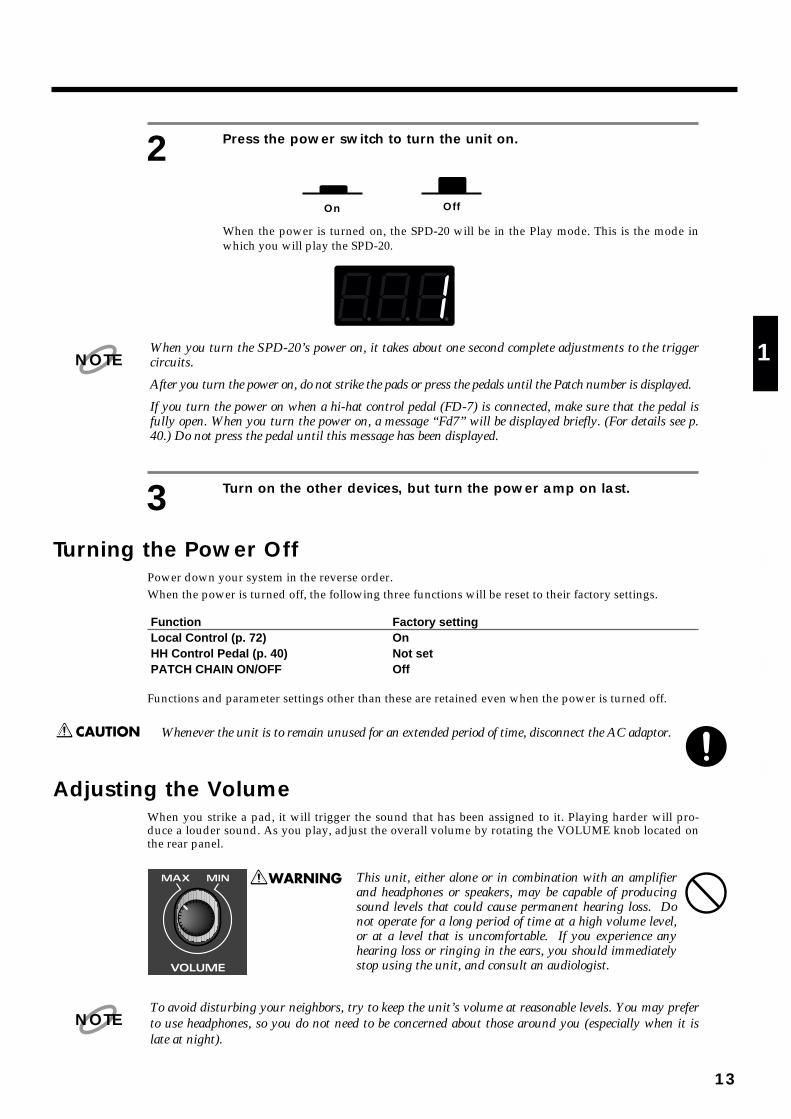
2 Press the power switch to turn the unit on.
fig.7
When the power is turned on, the SPD-20 will be in the Play mode. This is the mode inwhich you will play the SPD-20.
fig.8
When you turn the SPD-20’s power on, it takes about one second complete adjustments to the triggercircuits.
After you turn the power on, do not strike the pads or press the pedals until the Patch number is displayed.
If you turn the power on when a hi-hat control pedal (FD-7) is connected, make sure that the pedal isfully open. When you turn the power on, a message “Fd7” will be displayed briefly. (For details see p.40.) Do not press the pedal until this message has been displayed.
3 Turn on the other devices, but turn the power amp on last.
Turning the Power OffPower down your system in the reverse order.When the power is turned off, the following three functions will be reset to their factory settings.
Function Factory settingLocal Control (p. 72) OnHH Control Pedal (p. 40) Not setPATCH CHAIN ON/OFF Off
Functions and parameter settings other than these are retained even when the power is turned off.
Whenever the unit is to remain unused for an extended period of time, disconnect the AC adaptor.
Adjusting the VolumeWhen you strike a pad, it will trigger the sound that has been assigned to it. Playing harder will pro-duce a louder sound. As you play, adjust the overall volume by rotating the VOLUME knob located onthe rear panel.
fig.9
This unit, either alone or in combination with an amplifierand headphones or speakers, may be capable of producingsound levels that could cause permanent hearing loss. Donot operate for a long period of time at a high volume level,or at a level that is uncomfortable. If you experience anyhearing loss or ringing in the ears, you should immediatelystop using the unit, and consult an audiologist.
To avoid disturbing your neighbors, try to keep the unit’s volume at reasonable levels. You may preferto use headphones, so you do not need to be concerned about those around you (especially when it islate at night).
On Off
NOTE
NOTE
13
1
2
3
4
5

Selecting a PatchWhen you select a Patch, the sound assigned to each pad and the settings for MIDI, effect and pedal willall change instantly. Try each of the 99 factory-preset Patches to hear the different possibilities.
To select Patches first make sure you are in the Play mode. Then use the PATCH/VALUE [-] or [+] but-tons to select Patches. The number of the selected Patch will appear in the display.
Pressing PATCH/VALUE [+] while holding down PATCH/VALUE [-] (or vice versa) causes thePatch numbers to change more rapidly.
fig.10
The factory patch names are listed on p. 93.
What is a Patch?A Patch contains data determines how each pad sounds, settings for the effects and also MIDI settings.The SPD-20 can store 99 different Patches.
fig.11
When you select a Patch, the settings for each pad are instantly changed (p. 15).
You can also use MIDI Exclusive messages to store Patch data in an external sequencer or otherdevice (p. 75).
MEMO
Pad 2
External Pads1-4
Pad 3 Pad 4
Pad 6Pad 5 Pad 7 Pad 8
Internal Pads 1-8
+
Patch 99
Patch 1Sound Parameters • Instrument • Level • Pitch • Decay • Pan • Velocity Curve • Effect Send
MIDI Parameters • Transmit Channel • Note Number • Gate Time • Pan • Velocity Curve • Velocity Sensitivity • Program Change
Pad 1••
Hi-Hat Control PedalEffects
Pad 1
MEMO
14

Using a Footswitch to Select PatchesBy using a special cable (PCS-31; sold separately) to connect two footswitches (FS-5U; sold separately)
to the FOOT SW jack, you can select Patches by remote control. When you press Footswitch 1 you willadvance to the next Patch number, and when you press Footswitch 2 you will go back to the previousPatch number. If you connect a DP-2, you can move up (but not down) through the Patch numbers.
fig.12
Connect the two mono cables of the PCS-31 to the two footswitches. The plug with the white line is forFootswitch 1, and the plug with the red line is for Footswitch 2.
Connecting the model DP-2 pedal switch (sold separately) allows you to only advance the Patch numbers.
When using the footswitch as a Hold Pedal, please refer to “Using a Footwitch as a Hold Pedal” on p. 41.
Comparing Layered SoundsMost of the factory-preset Patches use Layer (p. 17). Select a layered Patch and listen to the sounds ofpad banks A and B. When you select a layered Patch, both PAD BANK indicators (A and B) will light.
1 Select a Patch.
2 In the Play mode, press [LAYER] to turn Layer off.
PAD BANK indicator B will go out. Now you can play the pads to hear the sound of padbank A.
3 To hear the sound of pad bank B, press [BANK A/B] so that PADBANK indicator B lights. Play the pads.
Each time you press [BANK A/B], PAD BANK indicators A and B will light alternately.
Footswitch 2(Previous Patch) (Next Patch)
Footswitch 1
(White)(Red)
Stereo
MonoMono POLALITY
You can make the setting with the FS-5U polarity switch, as shown in the figure below.
MEMO
MEMO
15
1
2
3
4
5
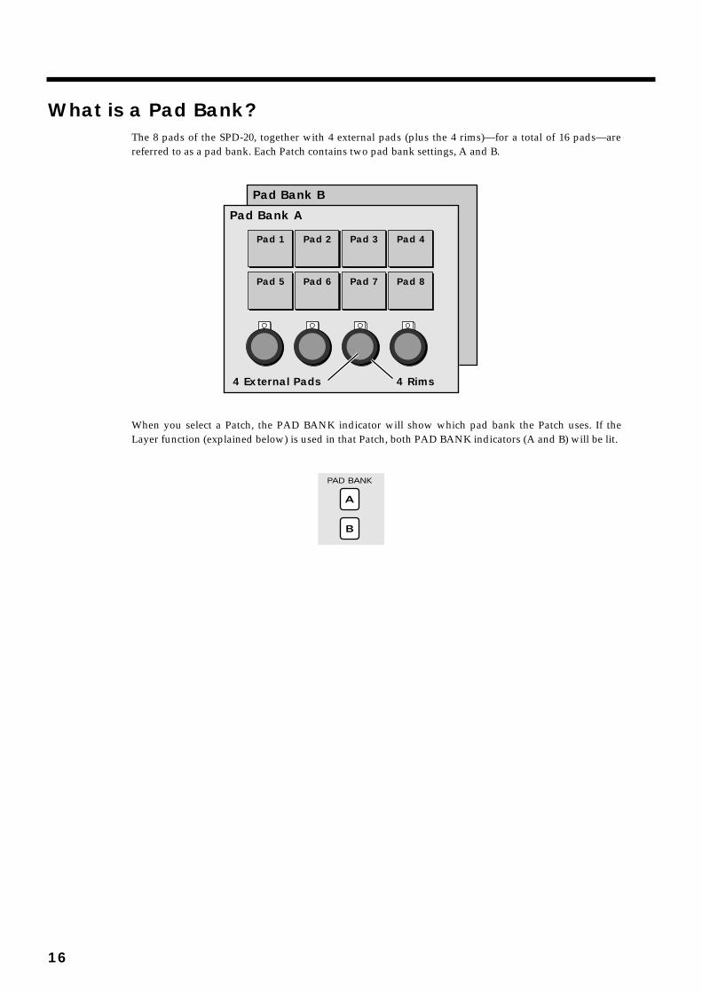
What is a Pad Bank?The 8 pads of the SPD-20, together with 4 external pads (plus the 4 rims)—for a total of 16 pads—arereferred to as a pad bank. Each Patch contains two pad bank settings, A and B.
fig.13
When you select a Patch, the PAD BANK indicator will show which pad bank the Patch uses. If theLayer function (explained below) is used in that Patch, both PAD BANK indicators (A and B) will be lit.
fig.14
Pad Bank B
Pad Bank A
Pad 2
4 Rims4 External Pads
Pad 1 Pad 3 Pad 4
Pad 6Pad 5 Pad 7 Pad 8
16
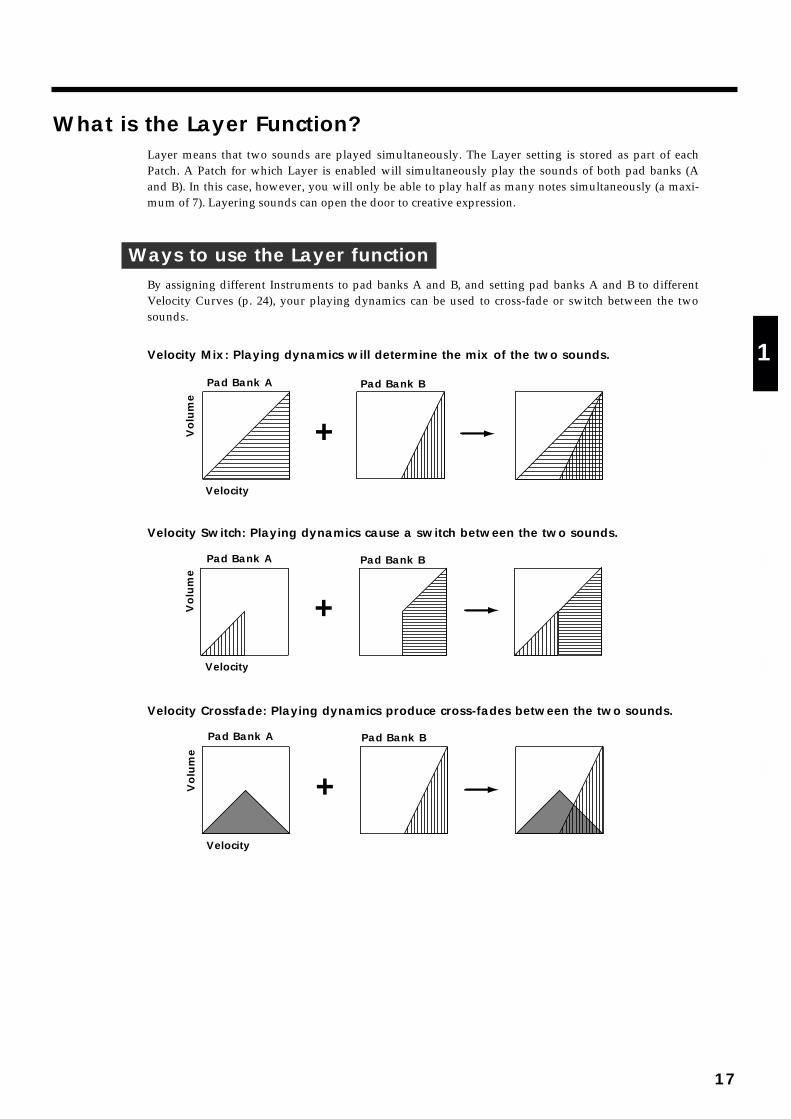
What is the Layer Function?Layer means that two sounds are played simultaneously. The Layer setting is stored as part of eachPatch. A Patch for which Layer is enabled will simultaneously play the sounds of both pad banks (Aand B). In this case, however, you will only be able to play half as many notes simultaneously (a maxi-mum of 7). Layering sounds can open the door to creative expression.
Ways to use the Layer functionBy assigning different Instruments to pad banks A and B, and setting pad banks A and B to differentVelocity Curves (p. 24), your playing dynamics can be used to cross-fade or switch between the twosounds.
Velocity Mix: Playing dynamics will determine the mix of the two sounds.fig.15-a
Velocity Switch: Playing dynamics cause a switch between the two sounds.fig.15-b
Velocity Crossfade: Playing dynamics produce cross-fades between the two sounds.fig.15-c
+Velocity
Volu
me
Pad Bank A Pad Bank B
+Velocity
Volu
me
Pad Bank A Pad Bank B
+Velocity
Volu
me
Pad Bank A Pad Bank B
17
1
2
3
4
5
About the SPD-20’s Internal Setup and Parameter Settings (Edit)This Chapter explains the basic structure of the SPD-20 and how it functions. Before we get into details,you should have an overall understanding of the unit.
What Kind of Instrument is the SPD-20?The SPD-20 is an electronic percussion instrument that produces sound when its pads are struck. Thistype of device is usually called a MIDI pad controller. The SPD-20 includes a sound generator (700sounds with 16-bit dynamic range) and digital effects unit in a compact and lightweight package. Byconnecting external pads or pedals (sold separately), you can obtain the same musical expressivity fromthe SPD-20 as you might enjoy with an acoustic drum kit. In addition, the SPD-20 is MIDI compatible,meaning that it can be connected to any other MIDI-compatible device (sequencer, sampler, etc.) regard-less of the manufacturer. This allows you to create a very powerful music system.
Product Overview• Self-contained compact MIDI pad controller
• 8 dynamics-sensitive pads
• 700 sounds with 16-bit dynamic range
• Built-in digital effects
• Expandable with external pads/pedals(such as the PD-7, PD-120, KD-7, and FD-7)
• Teams up with various MIDI units(such as sequencer, sampler, etc.)
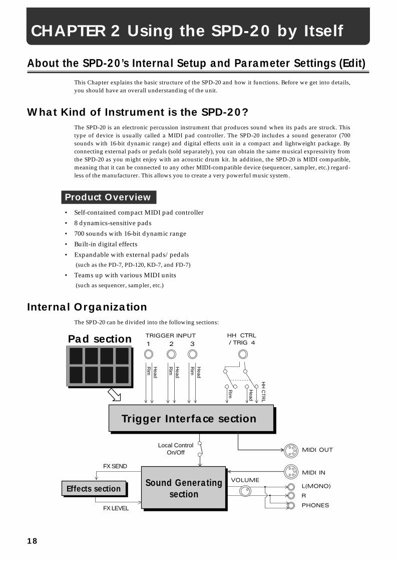
Internal OrganizationThe SPD-20 can be divided into the following sections:
fig.16
Trigger Interface section
Head
Rim
Head
Rim
Head
Rim
Head
HH
CT
RL
Rim
Pad section
Sound GeneratingsectionEffects section
FX SEND
FX LEVEL
Local ControlOn/Off
CHAPTER 2 Using the SPD-20 by Itself
18
Pad sectionThis section has 8 velocity sensitive pads that respond to changes in your playing dynamics.
Trigger Interface sectionThis section sends the trigger signals (electric signals produced when you strike a pad) to the SoundGenerating section.
Sound Generating sectionThis section receives signals from the trigger interface or MIDI IN, and produces sound in response. TheSPD-20 contains 700 sounds and up to 14 can be played simultaneously.
Effects sectionThis section adds effects (Flanger, Chorus, Reverb, Delay) to the sound from the sound generator. Youcan select from 25 effects combinations (p. 28).
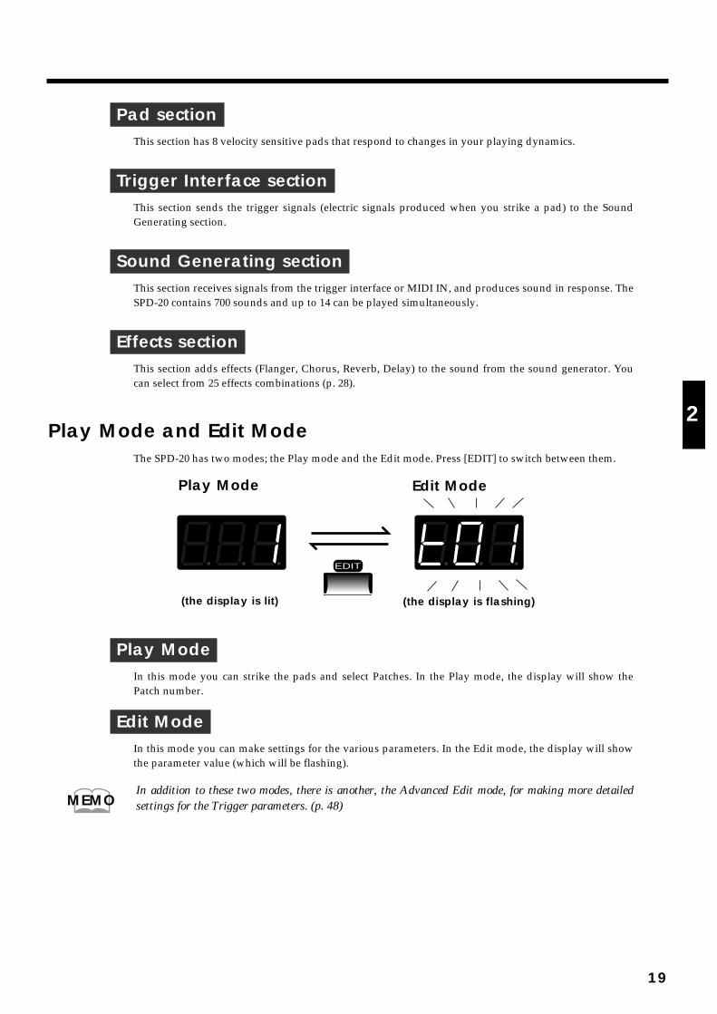
Play Mode and Edit ModeThe SPD-20 has two modes; the Play mode and the Edit mode. Press [EDIT] to switch between them.
fig.17
Play ModeIn this mode you can strike the pads and select Patches. In the Play mode, the display will show thePatch number.
Edit ModeIn this mode you can make settings for the various parameters. In the Edit mode, the display will showthe parameter value (which will be flashing).
In addition to these two modes, there is another, the Advanced Edit mode, for making more detailedsettings for the Trigger parameters. (p. 48)
EDIT
Edit ModePlay Mode
(the display is flashing)(the display is lit)
MEMO
19
1
2
3
4
5

How to EditTo modify parameter values you must be in the Edit mode. The names of all the parameters you canmodify are in the Parameter List printed on the front panel.
“Edit” refers to the process of changing parameter values.
How to read the parameter listThe parameter list has four indicators arranged horizontally and seven indicators arranged vertically. Inthe Edit mode, one of the horizontal indicators and one of the vertical indicators will always be lit. Thisshows which parameter is being edited; i.e., the intersection of the indicated column and row is the cur-rently selected parameter. The display shows the value of this parameter. To edit a particular parame-ter, refer to the parameter list and use the [SELECT] and [ ] [ ] buttons to select it.
fig.18
Use PATCH/VALUE [-] or [+] to modify the parameter value.
MEMO
Selected ParameterValue (flashing)
The intersection of theindicated column and row
TX CHNOTE #GT TIMEPANCURVESENSPGM CHG
INSTLEVELPITCHDECAYPANCURVEFX SEND
FX TYPEFX TIMEFX LEVELPDL CTRLPDL LEVELPDL CC #
BASIC CHBULK DUMPPATCH EXPANDTRIG SENSTRIG THRESHOLDTRIG TYPETRIG CURVE
can be setto each pad
can be set toeach Patch
can be set tothe entire system
MEMO
20
How to edit
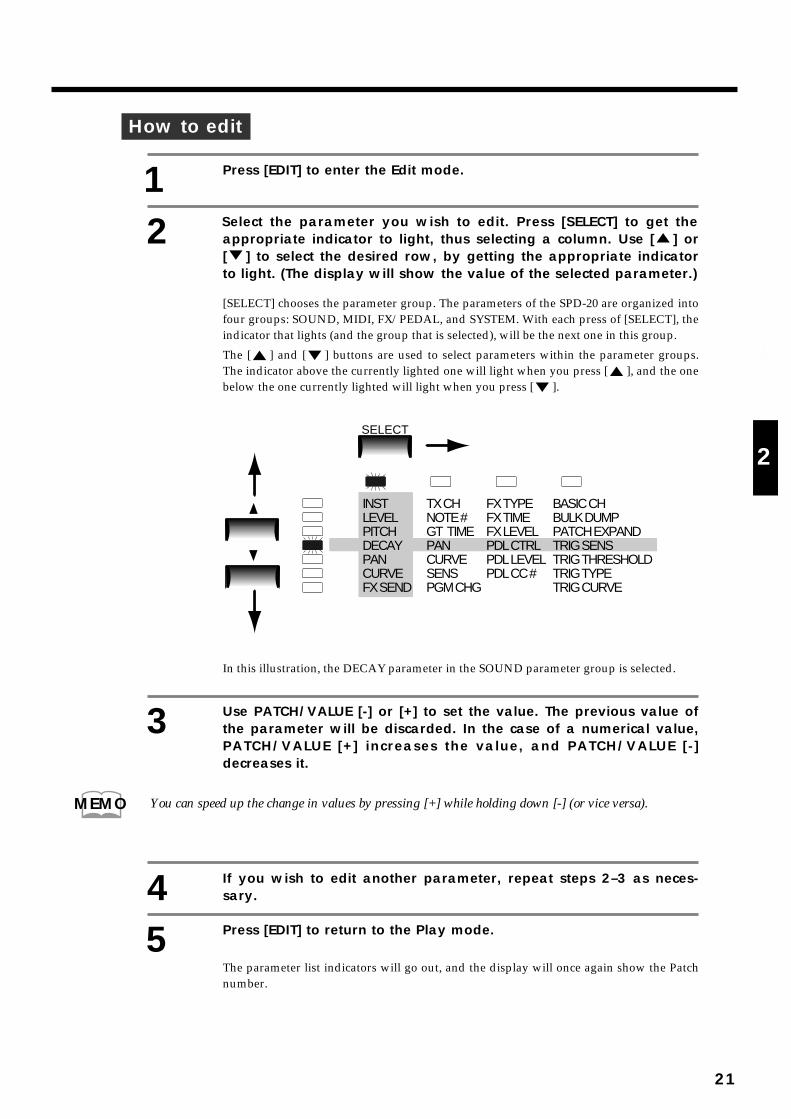
1 Press [EDIT] to enter the Edit mode.
2 Select the parameter you wish to edit. Press [SELECT] to get theappropriate indicator to light, thus selecting a column. Use [ ] or[ ] to select the desired row, by getting the appropriate indicatorto light. (The display will show the value of the selected parameter.)
[SELECT] chooses the parameter group. The parameters of the SPD-20 are organized intofour groups: SOUND, MIDI, FX/PEDAL, and SYSTEM. With each press of [SELECT], theindicator that lights (and the group that is selected), will be the next one in this group.
The [ ] and [ ] buttons are used to select parameters within the parameter groups.The indicator above the currently lighted one will light when you press [ ], and the onebelow the one currently lighted will light when you press [ ].
fig.19
In this illustration, the DECAY parameter in the SOUND parameter group is selected.
3 Use PATCH/VALUE [-] or [+] to set the value. The previous value ofthe parameter will be discarded. In the case of a numerical value,PATCH/VALUE [+] increases the value, and PATCH/VALUE [-]decreases it.
You can speed up the change in values by pressing [+] while holding down [-] (or vice versa).
4 If you wish to edit another parameter, repeat steps 2–3 as neces-sary.
5 Press [EDIT] to return to the Play mode.
The parameter list indicators will go out, and the display will once again show the Patchnumber.
TX CHNOTE #GT TIMEPANCURVESENSPGM CHG
FX TYPEFX TIMEFX LEVELPDL CTRLPDL LEVELPDL CC #
BASIC CHBULK DUMPPATCH EXPANDTRIG SENSTRIG THRESHOLDTRIG TYPETRIG CURVE
INSTLEVELPITCHDECAYPANCURVEFX SEND
SELECT
MEMO
21
1
2
3
4
5
Selecting and Adjusting Sounds (Sound Parameters)The parameters in the SOUND group (the sound parameters) allow you to modify the sound assignedto each pad.
The SOUND group contains 7 parameters: INST, LEVEL, PITCH, DECAY, PAN, CURVE and FX SEND.
Sound parameter settings for each pad are stored in each Patch.
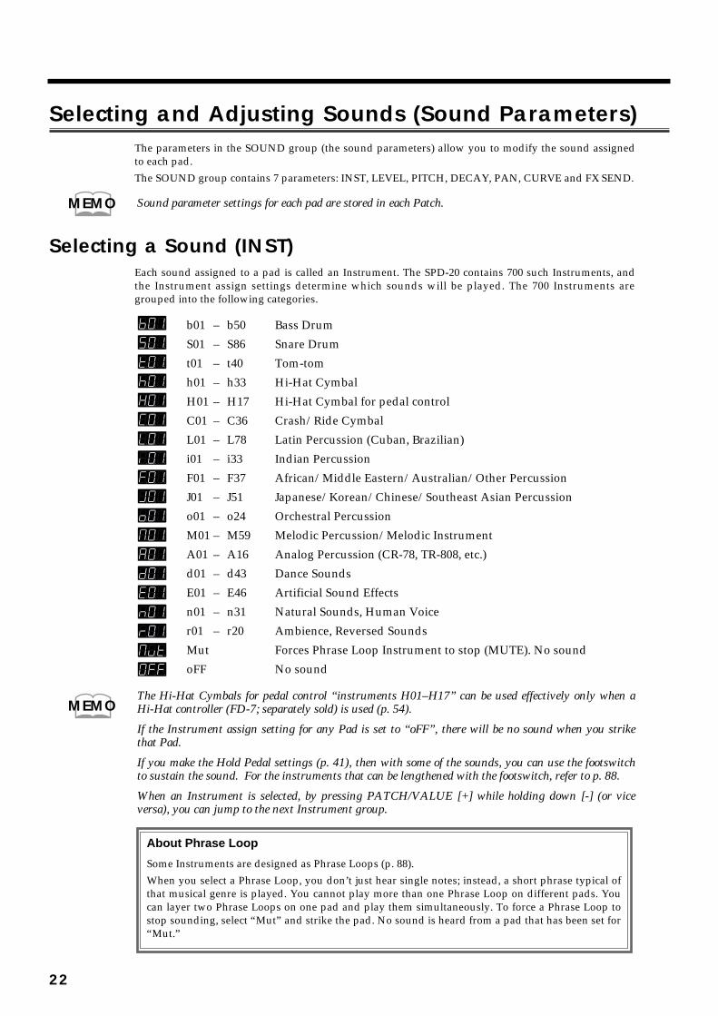
Selecting a Sound (INST)Each sound assigned to a pad is called an Instrument. The SPD-20 contains 700 such Instruments, andthe Instrument assign settings determine which sounds will be played. The 700 Instruments aregrouped into the following categories.
fig.96
b01 – b50 Bass Drum
S01 – S86 Snare Drum
t01 – t40 Tom-tom
h01 – h33 Hi-Hat Cymbal
H01 – H17 Hi-Hat Cymbal for pedal control
C01 – C36 Crash/Ride Cymbal
L01 – L78 Latin Percussion (Cuban, Brazilian)
i01 – i33 Indian Percussion
F01 – F37 African/Middle Eastern/Australian/Other Percussion
J01 – J51 Japanese/Korean/Chinese/Southeast Asian Percussion
o01 – o24 Orchestral Percussion
M01 – M59 Melodic Percussion/Melodic Instrument
A01 – A16 Analog Percussion (CR-78, TR-808, etc.)
d01 – d43 Dance Sounds
E01 – E46 Artificial Sound Effects
n01 – n31 Natural Sounds, Human Voice
r01 – r20 Ambience, Reversed Sounds
Mut Forces Phrase Loop Instrument to stop (MUTE). No sound
oFF No sound
The Hi-Hat Cymbals for pedal control “instruments H01–H17” can be used effectively only when aHi-Hat controller (FD-7; separately sold) is used (p. 54).
If the Instrument assign setting for any Pad is set to “oFF”, there will be no sound when you strikethat Pad.
If you make the Hold Pedal settings (p. 41), then with some of the sounds, you can use the footswitchto sustain the sound. For the instruments that can be lengthened with the footswitch, refer to p. 88.
When an Instrument is selected, by pressing PATCH/VALUE [+] while holding down [-] (or viceversa), you can jump to the next Instrument group.
MEMO
MEMO
About Phrase Loop
Some Instruments are designed as Phrase Loops (p. 88).
When you select a Phrase Loop, you don’t just hear single notes; instead, a short phrase typical ofthat musical genre is played. You cannot play more than one Phrase Loop on different pads. Youcan layer two Phrase Loops on one pad and play them simultaneously. To force a Phrase Loop tostop sounding, select “Mut” and strike the pad. No sound is heard from a pad that has been set for“Mut.”
22
Adjusting the Volume (LEVEL)This parameter determines the volume (0–15). At a setting of 0 there will be no sound.
When FX SEND in the SOUND parameter group is set above 0, the effects sound alone will be heardeven if the LEVEL parameter is set to 0.
Adjusting the Pitch (PITCH)This parameter determines the pitch of the Instrument (-24–+24). Each step will change the pitch by asemitone (100 cents).
For some Instruments, raising the pitch beyond a certain point will not be possible.
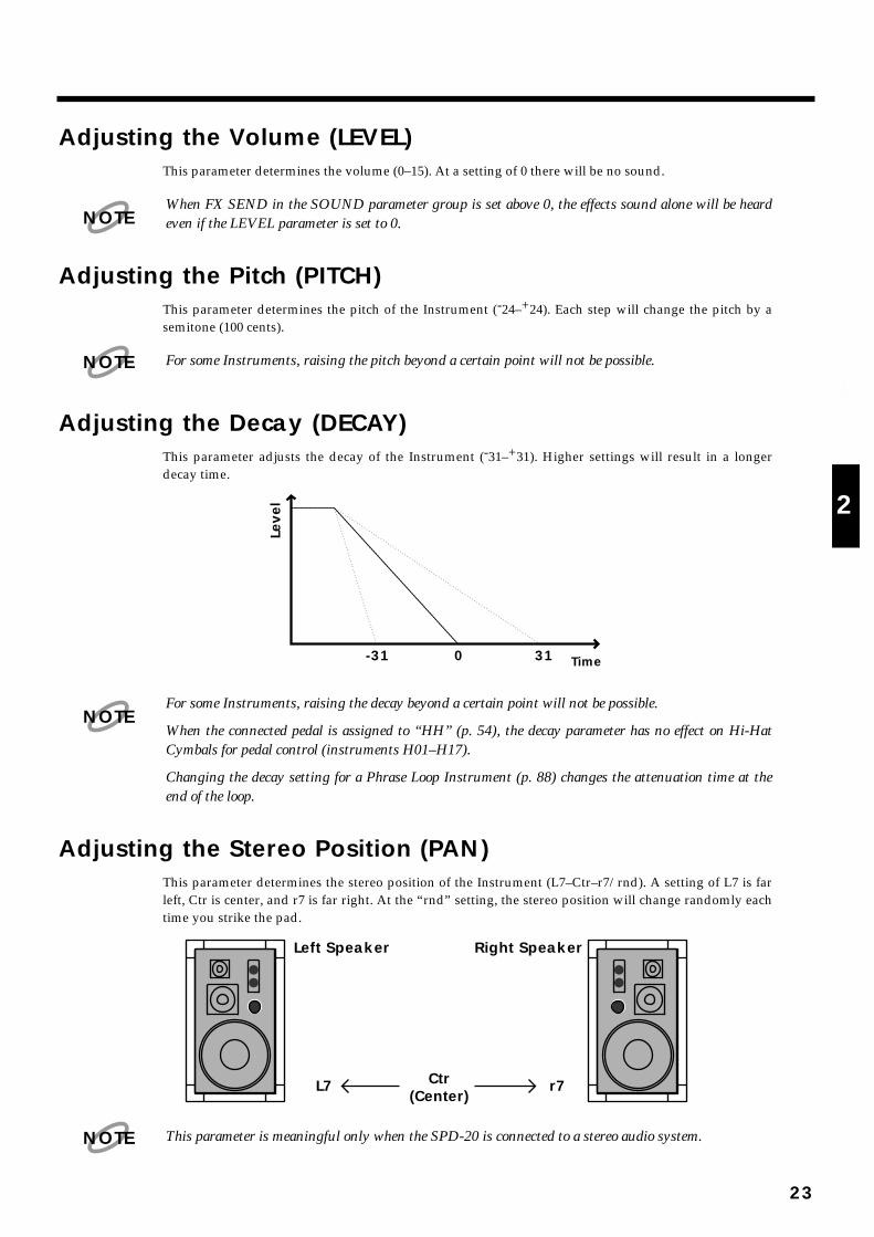
Adjusting the Decay (DECAY)This parameter adjusts the decay of the Instrument (-31–+31). Higher settings will result in a longerdecay time.
fig.20
For some Instruments, raising the decay beyond a certain point will not be possible.
When the connected pedal is assigned to “HH” (p. 54), the decay parameter has no effect on Hi-HatCymbals for pedal control (instruments H01–H17).
Changing the decay setting for a Phrase Loop Instrument (p. 88) changes the attenuation time at theend of the loop.
Adjusting the Stereo Position (PAN)This parameter determines the stereo position of the Instrument (L7–Ctr–r7/rnd). A setting of L7 is farleft, Ctr is center, and r7 is far right. At the “rnd” setting, the stereo position will change randomly eachtime you strike the pad.
fig.21
This parameter is meaningful only when the SPD-20 is connected to a stereo audio system.
NOTE
NOTE
Leve
l
Time310-31
NOTE
Right SpeakerLeft Speaker
Ctr(Center)
L7 r7
NOTE
23
1
2
3
4
5
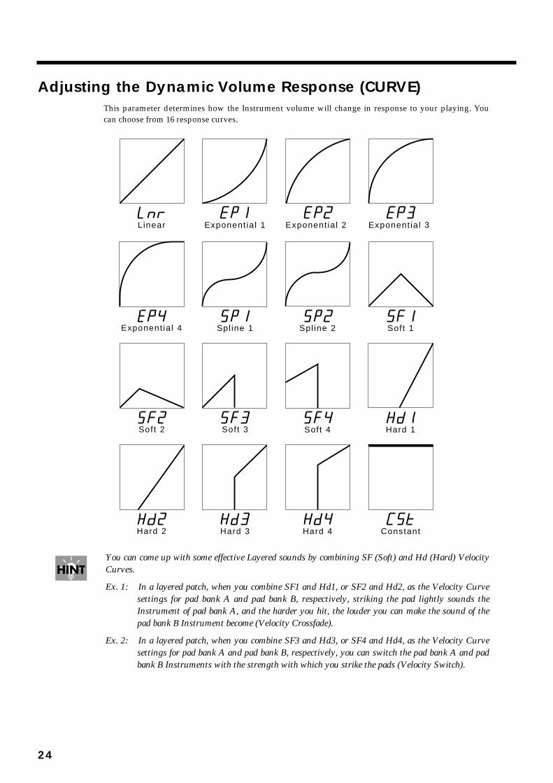
Adjusting the Dynamic Volume Response (CURVE)This parameter determines how the Instrument volume will change in response to your playing. Youcan choose from 16 response curves.
fig.22
You can come up with some effective Layered sounds by combining SF (Soft) and Hd (Hard) VelocityCurves.
Ex. 1: In a layered patch, when you combine SF1 and Hd1, or SF2 and Hd2, as the Velocity Curvesettings for pad bank A and pad bank B, respectively, striking the pad lightly sounds theInstrument of pad bank A, and the harder you hit, the louder you can make the sound of thepad bank B Instrument become (Velocity Crossfade).
Ex. 2: In a layered patch, when you combine SF3 and Hd3, or SF4 and Hd4, as the Velocity Curvesettings for pad bank A and pad bank B, respectively, you can switch the pad bank A and padbank B Instruments with the strength with which you strike the pads (Velocity Switch).
Exponent ia l 1 Exponent ia l 2 Exponent ia l 3 Linear
Spl ine 1 Soft 1Exponent ia l 4 Spl ine 2
Hard 1Soft 4
Hard 3 ConstantHard 2 Hard 4
Soft 2 Soft 3
24

fig.23 fig.24
When CSt is selected, the unit sounds at maximum volume, regardless of how hard you strike the pad.
Adjusting the Effects Depth (FX SEND)This parameter determines the depth (0–15) of the effect applied to each Instrument assigned to the pad.Higher settings will result in a deeper effect. With a setting of 0 there will be no effect. The overalleffects level for a Patch is determined by FX LEVEL in the FX/PEDAL parameter group.
fig.25
This FX SEND parameter will have an audible result only if the [FX ON/OFF] setting is on, and FXLEVEL in the FX/PEDAL parameter group is set above 0.
+
Pad Bank A Pad Bank B
Velocity Crossfade
Velocity Switch
Hard 1Soft 1
Hard 3Soft 3
+
Pad Bank A Pad Bank B
MEMO
FX SEND
Sound Generatingsection
Effects section
PANLEVEL
L/MONO
R
OUTPUT
FX LEVEL
NOTE
25
1
2
3
4
5
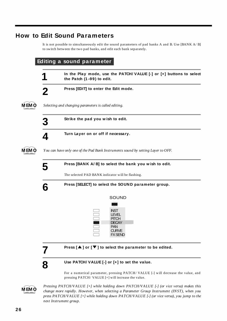
How to Edit Sound ParametersIt is not possible to simultaneously edit the sound parameters of pad banks A and B. Use [BANK A/B]to switch between the two pad banks, and edit each bank separately.
Editing a sound parameter
1 In the Play mode, use the PATCH/VALUE [-] or [+] buttons to selectthe Patch (1–99) to edit.
2 Press [EDIT] to enter the Edit mode.
Selecting and changing parameters is called editing.
3 Strike the pad you wish to edit.
4 Turn Layer on or off if necessary.
You can have only one of the Pad Bank Instruments sound by setting Layer to OFF.
5 Press [BANK A/B] to select the bank you wish to edit.
The selected PAD BANK indicator will be flashing.
6 Press [SELECT] to select the SOUND parameter group.
fig.26
7 Press [ ] or [ ] to select the parameter to be edited.
8 Use PATCH/VALUE [-] or [+] to set the value.
For a numerical parameter, pressing PATCH/VALUE [-] will decrease the value, andpressing PATCH/VALUE [+] will increase the value.
Pressing PATCH/VALUE [+] while holding down PATCH/VALUE [-] (or vice versa) makes thischange more rapidly. However, when selecting a Parameter Group Instrument (INST), when youpress PATCH/VALUE [+] while holding down PATCH/VALUE [-] (or vice versa), you jump to thenext Instrument group.
MEMO
MEMO
INSTLEVELPITCHDECAYPANCURVEFX SEND
MEMO
26
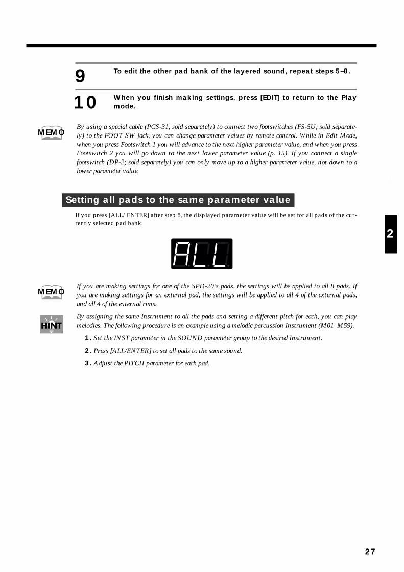
9 To edit the other pad bank of the layered sound, repeat steps 5–8.
10 When you finish making settings, press [EDIT] to return to the Playmode.
By using a special cable (PCS-31; sold separately) to connect two footswitches (FS-5U; sold separate-ly) to the FOOT SW jack, you can change parameter values by remote control. While in Edit Mode,when you press Footswitch 1 you will advance to the next higher parameter value, and when you pressFootswitch 2 you will go down to the next lower parameter value (p. 15). If you connect a singlefootswitch (DP-2; sold separately) you can only move up to a higher parameter value, not down to alower parameter value.
Setting all pads to the same parameter valueIf you press [ALL/ENTER] after step 8, the displayed parameter value will be set for all pads of the cur-rently selected pad bank.
fig.27
If you are making settings for one of the SPD-20’s pads, the settings will be applied to all 8 pads. Ifyou are making settings for an external pad, the settings will be applied to all 4 of the external pads,and all 4 of the external rims.
By assigning the same Instrument to all the pads and setting a different pitch for each, you can playmelodies. The following procedure is an example using a melodic percussion Instrument (M01–M59).
1. Set the INST parameter in the SOUND parameter group to the desired Instrument.
2. Press [ALL/ENTER] to set all pads to the same sound.
3. Adjust the PITCH parameter for each pad.
MEMO
MEMO
27
1
2
3
4
5
Adding Reverberation and Other Effects to the Sound(Effect Parameters)
The SPD-20 has four on-board effects: Reverb, Delay, Chorus, and Flanger. There are three effects para-meters: FX TYPE, FX TIME and FX LEVEL.
Effects settings are stored independently for each Patch, so you can set up the ideal effects for eachPatch.
Chapter 5 includes a section on “Taking Advantage of the On-board Effects” (p. 79), and we suggestthat you read this as well.
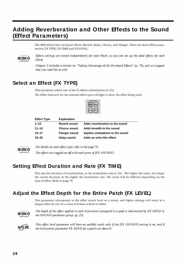
Select an Effect (FX TYPE)This parameter selects one of the 25 effects combinations (1–25).
The Effect Indicator for the selected effect type will light to show the effect being used.fig.27-a
Effect Type Explanation
1–10 Reverb sound Adds reverberation to the sound
11–14 Chorus sound Adds breadth to the sound
15–17 Flanger sound Applies undulations to the sound
18–25 Delay sound Adds an echo-like effect
For details on each effect type, refer to the page 79.
The effects are toggled on/off with each press of [FX ON/OFF].
Setting Effect Duration and Rate (FX TIME)This sets the duration of reverberation, or the modulation rate (1–32). The higher the value, the longerthe reverb duration, or the higher the modulation rate. The result will be different depending on thetype of effect. Refer to page 79.
Adjust the Effect Depth for the Entire Patch (FX LEVEL)This parameter corresponds to the effect return level on a mixer, and higher settings will result in adeeper effect (0–15). At a value of 0 there will be no effect.
The depth of the effect applied to each Instrument (assigned to a pad) is determined by FX SEND inthe SOUND parameter group. (p. 25)
This effect level parameter will have an audible result only if the [FX ON/OFF] setting is on, and ifthe Instrument parameter FX SEND for a pad is set above 0.
MEMO
MEMO
MEMO
NOTE
28
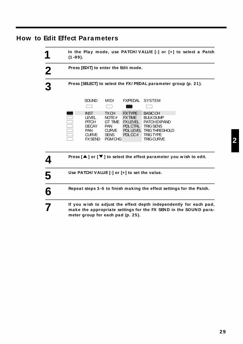
How to Edit Effect Parameters
1 In the Play mode, use PATCH/VALUE [-] or [+] to select a Patch(1–99).
2 Press [EDIT] to enter the Edit mode.
3 Press [SELECT] to select the FX/PEDAL parameter group (p. 21).
fig.28
4 Press [ ] or [ ] to select the effect parameter you wish to edit.
5 Use PATCH/VALUE [-] or [+] to set the value.
6 Repeat steps 3–5 to finish making the effect settings for the Patch.
7 If you wish to adjust the effect depth independently for each pad,make the appropriate settings for the FX SEND in the SOUND para-meter group for each pad (p. 25).
TX CHNOTE #GT TIMEPANCURVESENSPGM CHG
BASIC CHBULK DUMPPATCH EXPANDTRIG SENSTRIG THRESHOLDTRIG TYPETRIG CURVE
INSTLEVELPITCHDECAYPANCURVEFX SEND
FX/PEDAL SYSTEMMIDISOUND
FX TYPEFX TIMEFX LEVELPDL CTRLPDL LEVELPDL CC #
29
1
2
3
4
5
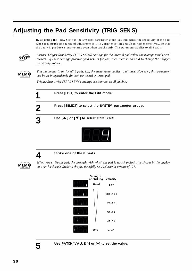
Adjusting the Pad Sensitivity (TRIG SENS)By adjusting the TRIG SENS in the SYSTEM parameter group you can adjust the sensitivity of the padwhen it is struck (the range of adjustment is 1–16). Higher settings result in higher sensitivity, so thatthe pad will produce a loud volume even when struck softly. This parameter applies to all 8 pads.
Factory Trigger Sensitivity (TRIG SENS) settings for the internal pad reflect the average user´s pref-erences. If these settings produce good results for you, then there is no need to change the TriggerSensitivity values.
This parameter is set for all 8 pads, i.e., the same value applies to all pads. However, this parametercan be set independently for each connected external pad.
Trigger Sensitivity (TRIG SENS) settings are common to all patches.
1 Press [EDIT] to enter the Edit mode.
2 Press [SELECT] to select the SYSTEM parameter group.
3 Use [ ] or [ ] to select TRIG SENS.
fig.29
4 Strike one of the 8 pads.
When you strike the pad, the strength with which the pad is struck (velocity) is shown in the displayon a six-level scale. Striking the pad forcefully sets velocity at a value of 127.
fig.95
5 Use PATCH/VALUE [-] or [+] to set the value.
NOTE
MEMO
MEMO
VelocityStrength
of Striking
Hard 127
100–126
75–99
50–74
25–49
1–24Soft
30
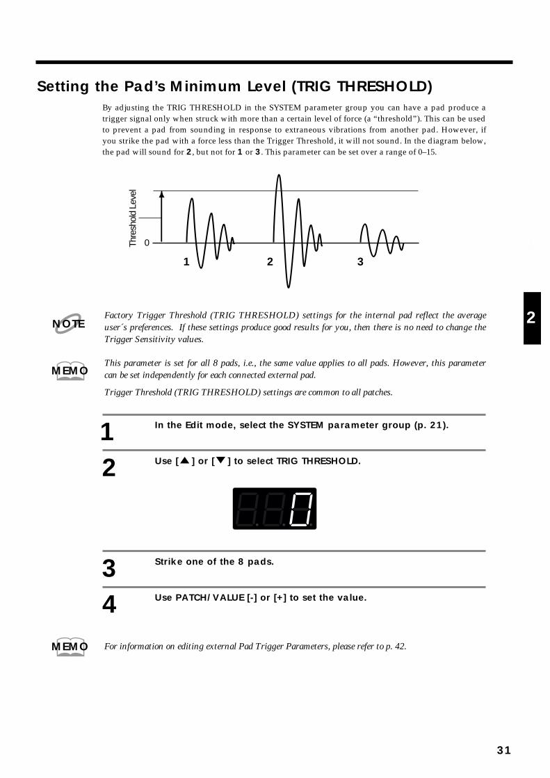
Setting the Pad’s Minimum Level (TRIG THRESHOLD)By adjusting the TRIG THRESHOLD in the SYSTEM parameter group you can have a pad produce atrigger signal only when struck with more than a certain level of force (a “threshold”). This can be usedto prevent a pad from sounding in response to extraneous vibrations from another pad. However, ifyou strike the pad with a force less than the Trigger Threshold, it will not sound. In the diagram below,the pad will sound for 2, but not for 1 or 3. This parameter can be set over a range of 0–15.
fig.30
Factory Trigger Threshold (TRIG THRESHOLD) settings for the internal pad reflect the averageuser´s preferences. If these settings produce good results for you, then there is no need to change theTrigger Sensitivity values.
This parameter is set for all 8 pads, i.e., the same value applies to all pads. However, this parametercan be set independently for each connected external pad.
Trigger Threshold (TRIG THRESHOLD) settings are common to all patches.
1 In the Edit mode, select the SYSTEM parameter group (p. 21).
2 Use [ ] or [ ] to select TRIG THRESHOLD.
fig.31
3 Strike one of the 8 pads.
4 Use PATCH/VALUE [-] or [+] to set the value.
For information on editing external Pad Trigger Parameters, please refer to p. 42.
1 2 3
Thre
shol
d Le
vel
0
NOTE
MEMO
MEMO
31
1
2
3
4
5

Copying a Patch (COPY) This operation copies Patch settings to another Patch. If you need another Patch that is only slightly dif-ferent from an existing one, copy that Patch and then make the changes that you need.
fig.29-1
When you execute COPY, the contents of the copy destination patch are rewritten.
1 In the Play mode, use PATCH/VALUE [-] or [+] to select the copy des-tination Patch (1–99).When you execute COPY, the data is overwritten in this patch.
2 Press [EDIT] to enter the Edit mode.
3 Press [COPY].
fig.32
4 Use PATCH/VALUE [-] or [+] to select the copy source Patch.
The copy source Patch can be selected from user Patches (U1–U99) or factory-preset Patches (P1–P99).
Play the pads to check the selected copy source Patch.
To quit without copying, press [COPY].
5 Press [ALL/ENTER] and the Patch will be copied.
fig.32-a
6 Press [EDIT] once again to return to the Play mode.
The external pad’s SOUND parameter, MIDI parameter, and FX/PEDAL settings are copied simulta-neously.
Copy source
User Patch U1-U99Preset Patch P1-P99
User Patch U1-U99
Patch
Copy destination
Patch
MEMO
MEMO
MEMO
32
Setting Up Your Own Patch Sequences (Patch Chain)
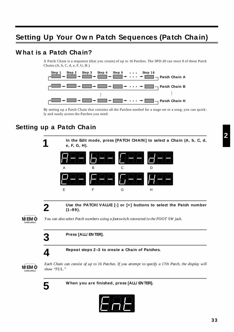
What is a Patch Chain?A Patch Chain is a sequence (that you create) of up to 16 Patches. The SPD-20 can store 8 of these PatchChains (A, b, C, d, e, F, G, H.)
fig.33
By setting up a Patch Chain that contains all the Patches needed for a stage set or a song, you can quick-ly and easily access the Patches you need.
Setting up a Patch Chain
1 In the Edit mode, press [PATCH CHAIN] to select a Chain (A, b, C, d,e, F, G, H).
fig.36
2 Use the PATCH/VALUE [-] or [+] buttons to select the Patch number(1–99).
You can also select Patch numbers using a footswitch connected to the FOOT SW jack.
3 Press [ALL/ENTER].
4 Repeat steps 2–3 to create a Chain of Patches.
Each Chain can consist of up to 16 Patches. If you attempt to specify a 17th Patch, the display willshow “FUL.”
5 When you are finished, press [ALL/ENTER].
fig.35
Step 1 Step 2 Step 3 Step 4 Step 16Step 5 • • •• • •
• • •
• • •
Patch Chain A
Patch Chain B
Patch Chain H
A B C D
E F G H
MEMO
MEMO
33
1
2
3
4
5
If you press [PATCH CHAIN] to select another Chain before pressing [ALL/ENTER], the PatchChain settings you just made will be lost.
6 If you wish, you may make settings for another Patch Chain.
7 When you finish making Patch Chain settings, press [EDIT] to returnto the Play mode.
Using a Patch Chain to Select PatchesHere’s how to step through the Patches in a Patch Chain.
1 In the Play mode, press [PATCH CHAIN] to select the Patch Chainyou wish to use (A, b, C, d, e, F, G,H).
fig.36
A Patch Chain which does not contain any data will not be displayed in the Play mode.
2 Each time you press PATCH/VALUE [-] or [+]the next Patch in theChain will be selected.
After the last Patch in the Chain, you will return to the first Patch.
A footswitch connected to the FOOT SW jack can also be used to select Patches.
3 Press [PATCH CHAIN] several times to return to the Play mode.
Erasing a Patch ChainHere’s how to erase the current Patch Chain settings.
1 Press [EDIT] to enter the Edit mode.
2 Use [PATCH CHAIN] to select a Patch Chain, and press [ALL/ENTER]to erase it. The following display will appear.
fig.37
3 Press [EDIT] once again to return to the Play mode.
After all chains are cleared, the Patch Chain cannot be used, even if you press [PATCH CHAIN] inthe Play mode.
NOTE
NOTE
MEMO
NOTE
34
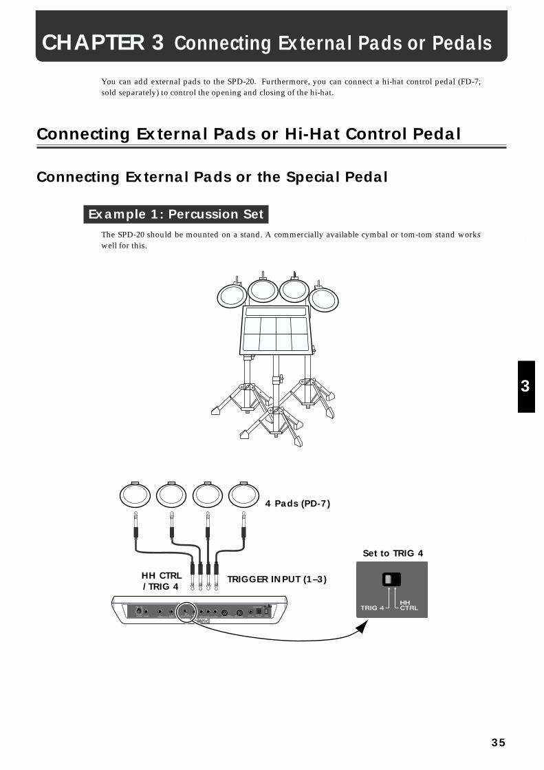
You can add external pads to the SPD-20. Furthermore, you can connect a hi-hat control pedal (FD-7;sold separately) to control the opening and closing of the hi-hat.
Connecting External Pads or Hi-Hat Control Pedal
Connecting External Pads or the Special Pedal
Example 1: Percussion SetThe SPD-20 should be mounted on a stand. A commercially available cymbal or tom-tom stand workswell for this.
fig.38
Set to TRIG 4
4 Pads (PD-7)
TRIGGER INPUT (1–3)HH CTRL/TRIG 4
CHAPTER 3 Connecting External Pads or Pedals
35
1
2
3
4
5

Example 2: Full Set KitIf you wish to connect a hi-hat control pedal (FD-7; sold separately) to the HH CTRL/TRIG 4 jack, setthe [HH CTRL/TRIG 4] select switch (p. 40) to HH CTRL. If you wish to connect an external pad, set theswitch to TRIG 4.
fig.39
Set to HH CTRL
TRIGGER INPUT (1–3)HH CTRL/TRIG 4
TRIG 1
TRIG 2TRIG 3
HH CTRL/TRIG 4
Pad (PD-7)
Pad (PD-120) Kick Trigger Unit (KD-7) + Kick Pedal
Hi-Hat Control Pedal (FD-7)
Roland
Tom1
Crash Splash Ride China
Tom2 Tom3 Tom4
Kick
Snare
Hi-Hat
Hi-Hat Control Pedal
36
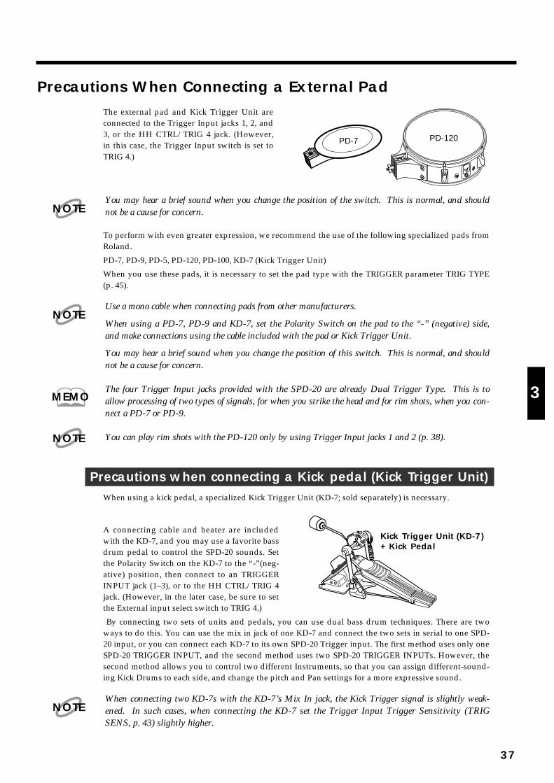
Precautions When Connecting a External Padfig.40
The external pad and Kick Trigger Unit areconnected to the Trigger Input jacks 1, 2, and3, or the HH CTRL/TRIG 4 jack. (However,in this case, the Trigger Input switch is set toTRIG 4.)
You may hear a brief sound when you change the position of the switch. This is normal, and shouldnot be a cause for concern.
To perform with even greater expression, we recommend the use of the following specialized pads fromRoland.
PD-7, PD-9, PD-5, PD-120, PD-100, KD-7 (Kick Trigger Unit)
When you use these pads, it is necessary to set the pad type with the TRIGGER parameter TRIG TYPE(p. 45).
Use a mono cable when connecting pads from other manufacturers.
When using a PD-7, PD-9 and KD-7, set the Polarity Switch on the pad to the “-” (negative) side,and make connections using the cable included with the pad or Kick Trigger Unit.
You may hear a brief sound when you change the position of this switch. This is normal, and shouldnot be a cause for concern.
The four Trigger Input jacks provided with the SPD-20 are already Dual Trigger Type. This is toallow processing of two types of signals, for when you strike the head and for rim shots, when you con-nect a PD-7 or PD-9.
You can play rim shots with the PD-120 only by using Trigger Input jacks 1 and 2 (p. 38).
Precautions when connecting a Kick pedal (Kick Trigger Unit)When using a kick pedal, a specialized Kick Trigger Unit (KD-7; sold separately) is necessary.
fig.41
A connecting cable and beater are includedwith the KD-7, and you may use a favorite bassdrum pedal to control the SPD-20 sounds. Setthe Polarity Switch on the KD-7 to the “-”(neg-ative) position, then connect to an TRIGGERINPUT jack (1–3), or to the HH CTRL/TRIG 4jack. (However, in the later case, be sure to setthe External input select switch to TRIG 4.)
By connecting two sets of units and pedals, you can use dual bass drum techniques. There are twoways to do this. You can use the mix in jack of one KD-7 and connect the two sets in serial to one SPD-20 input, or you can connect each KD-7 to its own SPD-20 Trigger input. The first method uses only oneSPD-20 TRIGGER INPUT, and the second method uses two SPD-20 TRIGGER INPUTs. However, thesecond method allows you to control two different Instruments, so that you can assign different-sound-ing Kick Drums to each side, and change the pitch and Pan settings for a more expressive sound.
When connecting two KD-7s with the KD-7’s Mix In jack, the Kick Trigger signal is slightly weak-ened. In such cases, when connecting the KD-7 set the Trigger Input Trigger Sensitivity (TRIGSENS, p. 43) slightly higher.
PD-7 PD-120
NOTE
NOTE
MEMO
NOTE
Kick Trigger Unit (KD-7)+ Kick Pedal
NOTE
37
1
2
3
4
5
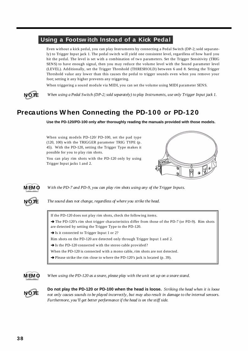
Using a Footswitch Instead of a Kick PedalEven without a kick pedal, you can play Instruments by connecting a Pedal Switch (DP-2; sold separate-ly) to Trigger Input jack 1. The pedal switch will yield one consistent level, regardless of how hard youhit the pedal. The level is set with a combination of two parameters. Set the Trigger Sensitivity (TRIGSENS) to have enough signal, then you may reduce the volume level with the Sound parameter level(LEVEL). Additionally, set the Trigger Threshold (THRESHOLD) between 6 and 8. Setting the TriggerThreshold value any lower than this causes the pedal to trigger sounds even when you remove yourfoot; setting it any higher prevents any triggering.
When triggering a sound module via MIDI, you can set the volume using MIDI parameter SENS.
When using a Pedal Switch (DP-2; sold separately) to play Instruments, use only Trigger Input jack 1.
Precautions When Connecting the PD-100 or PD-120Use the PD-120/PD-100 only after thoroughly reading the manuals provided with those models.
fig.42
When using models PD-120/PD-100, set the pad type(120, 100) with the TRIGGER parameter TRIG TYPE (p.45). With the PD-120, setting the Trigger Type makes itpossible for you to play rim shots.
You can play rim shots with the PD-120 only by usingTrigger Input jacks 1 and 2.
With the PD-7 and PD-9, you can play rim shots using any of the Trigger Inputs.
The sound does not change, regardless of where you strike the head.
When using the PD-120 as a snare, please play with the unit set up on a snare stand.
Do not play the PD-120 or PD-100 when the head is loose. Striking the head when it is loosenot only causes sounds to be played incorrectly, but may also result in damage to the internal sensors.Furthermore, you’ll get better performance if the head is on the stiff side.
NOTE
MEMO
NOTE
If the PD-120 does not play rim shots, check the following items.
➜ The PD-120’s rim shot trigger characteristics differ from those of the PD-7 (or PD-9). Rim shotsare detected by setting the Trigger Type to the PD-120.
➜ Is it connected to Trigger Input 1 or 2?
Rim shots on the PD-120 are detected only through Trigger Input 1 and 2.
➜ Is the PD-120 connected with the stereo cable provided?
When the PD-120 is connected with a mono cable, rim shots are not detected.
➜ Please strike the rim close to where the PD-120’s jack is located (p. 39).
MEMO
NOTE
38

How to Use the Rim Shot and Cymbal Choke Playing TechniquesIf a PD-7 or PD-9 is connected, you will be able to use Rim Shot and Cymbal Choke playing technique.If a PD-120 is connected, you will be able to use Rim Shot playing technique.
Rim ShotBy playing Rim Shot, you can play two types of sound from one pad. This can be done with a PD-7, PD-9, PD-120.
At the time the unit was shipped from the factory, the Snare Drum Rim Shot Instrument was set toPatch 1 Trigger Input 2; confirm this by actually striking the pad.
Normal shot: Strike only the head (center)
Rim shot: Strike both the head and the rim (perimeter) simultaneously.fig.43
When playing rim shots, striking only the rim does not produce a solid rim shot sound. Be sure tostrike both the head and rim at the same time. With rim shots how hard the drum is struck is detectedin the head portion.
fig.44
When you play rim shots on the PD-120, with the padOUTPUT jack facing toward you as shown in the figure,strike the rim within the range shown. By making rimshots outside this range you will not be able to achieve areliable rim shot sound.
rim shots can be played on the PD-120 only throughTrigger Input 1 and 2.
With the SPD-20, you can choose two separate MIDIsound modules for a dual trigger pad, i.e. send the “headonly” to MIDI channel 10, and the “rim” to MIDI chan-nel 11. This allows you to control instruments from twoMIDI systems with one PD-7, PD-9, or PD-120 (p. 66).
Cymbal ChokeWith the PD-7 and PD-9, physically grasping the rim of the pad just after the pad is struck stops thesound as it is made. This allows you to make the same sound you get when you stop the cymbal fromsounding with your hand just after striking it.
fig.45
MEMO
Pad
Rim of the Pad
Rim ShotCenter of Pad
Pad
NOTE
Range within which rim shots can be made
HE
AD
MA
DE
BY
RE
MO
U.S
.A.
Toward the player
OUTPUTJackNOTE
MEMO
39
1
2
3
4
5
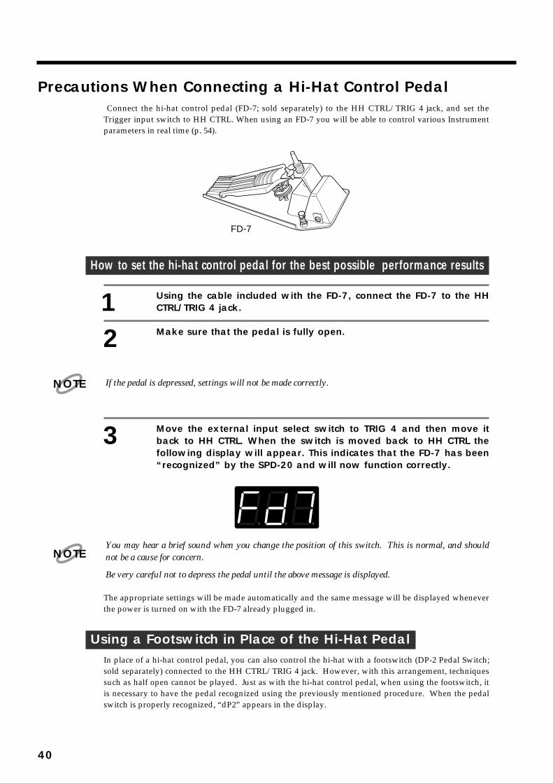
Precautions When Connecting a Hi-Hat Control PedalConnect the hi-hat control pedal (FD-7; sold separately) to the HH CTRL/TRIG 4 jack, and set the
Trigger input switch to HH CTRL. When using an FD-7 you will be able to control various Instrumentparameters in real time (p. 54).
fig.46
How to set the hi-hat control pedal for the best possible performance results
1 Using the cable included with the FD-7, connect the FD-7 to the HHCTRL/TRIG 4 jack.
2 Make sure that the pedal is fully open.
If the pedal is depressed, settings will not be made correctly.
3 Move the external input select switch to TRIG 4 and then move itback to HH CTRL. When the switch is moved back to HH CTRL thefollowing display will appear. This indicates that the FD-7 has been“recognized” by the SPD-20 and will now function correctly.
fig. 47
You may hear a brief sound when you change the position of this switch. This is normal, and shouldnot be a cause for concern.
Be very careful not to depress the pedal until the above message is displayed.
The appropriate settings will be made automatically and the same message will be displayed wheneverthe power is turned on with the FD-7 already plugged in.
Using a Footswitch in Place of the Hi-Hat PedalIn place of a hi-hat control pedal, you can also control the hi-hat with a footswitch (DP-2 Pedal Switch;sold separately) connected to the HH CTRL/TRIG 4 jack. However, with this arrangement, techniquessuch as half open cannot be played. Just as with the hi-hat control pedal, when using the footswitch, itis necessary to have the pedal recognized using the previously mentioned procedure. When the pedalswitch is properly recognized, “dP2” appears in the display.
FD-7
NOTE
NOTE
40

Using a Footswitch as a Hold PedalA footswitch (DP-2/FS-5U; sold separately) connected to the FOOT SW jack can be used as a hold (sus-tain) pedal to control specified Instruments and external MIDI sound modules. When you depress thepedal, a Control Change message (Hold) will be transmitted, instructing the MIDI sound modules tocontinue sounding the notes that are currently being played.
If you turn the SPD-20 on while the footswitch is depressed, the following message will scroll across thedisplay and the footswitch will act as a hold pedal.
fig.48
If you are using an FS-5U, Footswitch 1 with PCS-31 will act as the hold pedal, and Footswitch 2 willincrease the Patch number.
The SPD-20’s display can only show 3 characters at once. To “scroll” means that the characters auto-matically move across the display to show a longer message. The SPD-20 will sometimes scroll errormessages or other helpful information (p. 87).
Hold messages will be transmitted on the channel specified by the Basic Channel.
There are specific Instruments in the internal sound generator that can also be held with a footswitch(p. 88).
This may not work properly for some MIDI sound modules or some sounds.
When using the footswitch as a Patch Shift Pedal (p. 15), first turn off the power to the unit, then withthe footswitch depressed, turn the power back on. The following message is displayed, and thefootswitch is set to function as a Patch Shift Pedal.
The footswitch can function as a “Patch Shift Pedal” or a “Hold Pedal.”
Each time the power is turned on with the footswitch in the depressed position, the function is switchedbetween “Patch Shift Pedal” and “Hold Pedal.” The footswitch setting is set at the factory to “PatchShift Pedal.”
NOTE
MEMO
NOTE
41
1
2
3
4
5
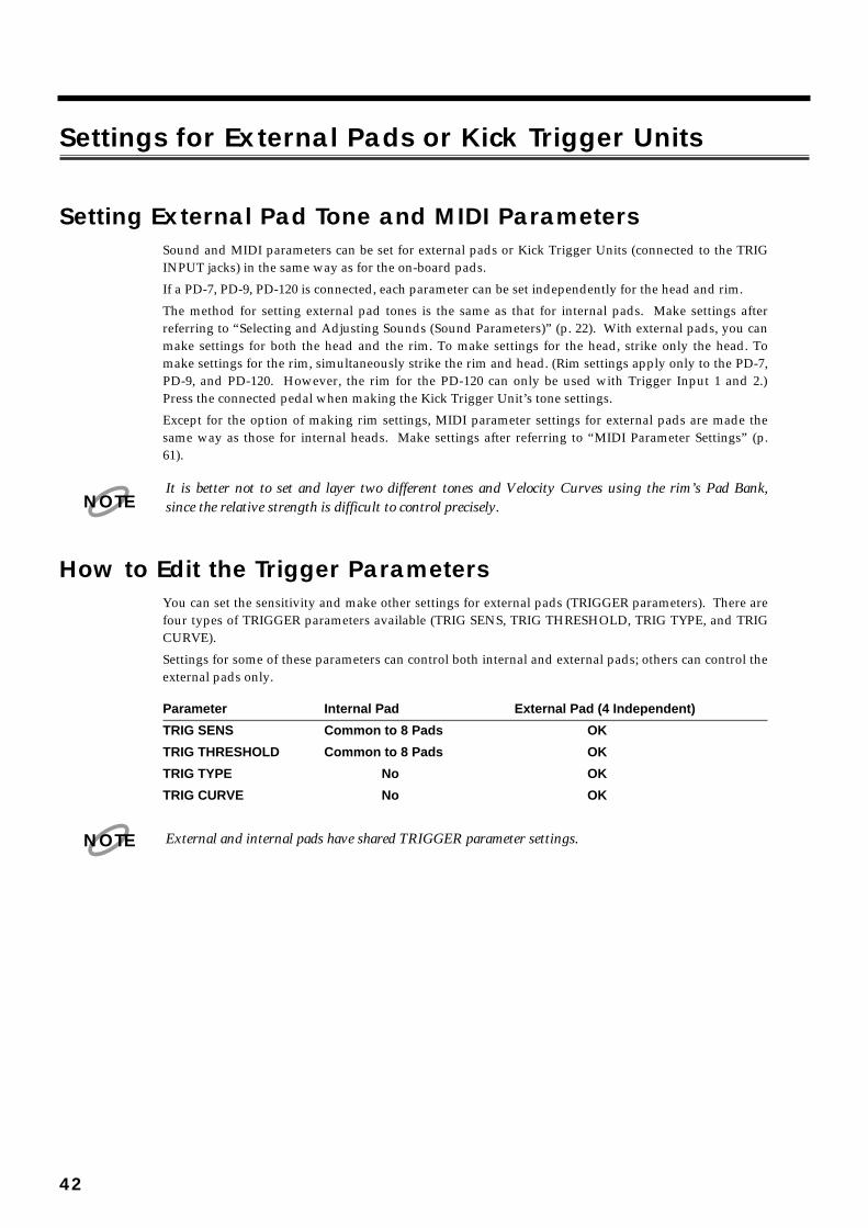
Settings for External Pads or Kick Trigger Units
Setting External Pad Tone and MIDI ParametersSound and MIDI parameters can be set for external pads or Kick Trigger Units (connected to the TRIGINPUT jacks) in the same way as for the on-board pads.
If a PD-7, PD-9, PD-120 is connected, each parameter can be set independently for the head and rim.
The method for setting external pad tones is the same as that for internal pads. Make settings afterreferring to “Selecting and Adjusting Sounds (Sound Parameters)” (p. 22). With external pads, you canmake settings for both the head and the rim. To make settings for the head, strike only the head. Tomake settings for the rim, simultaneously strike the rim and head. (Rim settings apply only to the PD-7,PD-9, and PD-120. However, the rim for the PD-120 can only be used with Trigger Input 1 and 2.)Press the connected pedal when making the Kick Trigger Unit’s tone settings.
Except for the option of making rim settings, MIDI parameter settings for external pads are made thesame way as those for internal heads. Make settings after referring to “MIDI Parameter Settings” (p.61).
It is better not to set and layer two different tones and Velocity Curves using the rim’s Pad Bank,since the relative strength is difficult to control precisely.
How to Edit the Trigger ParametersYou can set the sensitivity and make other settings for external pads (TRIGGER parameters). There arefour types of TRIGGER parameters available (TRIG SENS, TRIG THRESHOLD, TRIG TYPE, and TRIGCURVE).
Settings for some of these parameters can control both internal and external pads; others can control theexternal pads only.
Parameter Internal Pad External Pad (4 Independent)
TRIG SENS Common to 8 Pads OK
TRIG THRESHOLD Common to 8 Pads OK
TRIG TYPE No OK
TRIG CURVE No OK
External and internal pads have shared TRIGGER parameter settings.
NOTE
NOTE
42
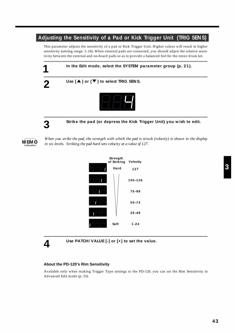
Adjusting the Sensitivity of a Pad or Kick Trigger Unit (TRIG SENS)This parameter adjusts the sensitivity of a pad or Kick Trigger Unit. Higher values will result in highersensitivity (setting range: 1–16). When external pads are connected, you should adjust the relative sensi-tivity between the external and on-board pads so as to provide a balanced feel for the entire drum kit.
1 In the Edit mode, select the SYSTEM parameter group (p. 21).
2 Use [ ] or [ ] to select TRIG SENS.
fig.49
3 Strike the pad (or depress the Kick Trigger Unit) you wish to edit.
When you strike the pad, the strength with which the pad is struck (velocity) is shown in the displayin six levels. Striking the pad hard sets velocity at a value of 127.
fig.95
4 Use PATCH/VALUE [-] or [+] to set the value.
About the PD-120’s Rim Sensitivity
Available only when making Trigger Type settings to the PD-120, you can set the Rim Sensitivity inAdvanced Edit mode (p. 53).
MEMO
VelocityStrength
of Striking
Hard 127
100–126
75–99
50–74
25–49
1–24Soft
43
1
2
3
4
5
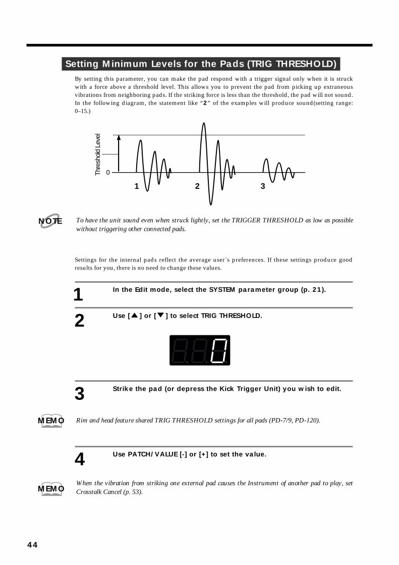
Setting Minimum Levels for the Pads (TRIG THRESHOLD)By setting this parameter, you can make the pad respond with a trigger signal only when it is struckwith a force above a threshold level. This allows you to prevent the pad from picking up extraneousvibrations from neighboring pads. If the striking force is less than the threshold, the pad will not sound.In the following diagram, the statement like “2” of the examples will produce sound(setting range:0–15.)
fig.50
To have the unit sound even when struck lightly, set the TRIGGER THRESHOLD as low as possiblewithout triggering other connected pads.
Settings for the internal pads reflect the average user´s preferences. If these settings produce goodresults for you, there is no need to change these values.
1 In the Edit mode, select the SYSTEM parameter group (p. 21).
2 Use [ ] or [ ] to select TRIG THRESHOLD.
fig.51
3 Strike the pad (or depress the Kick Trigger Unit) you wish to edit.
Rim and head feature shared TRIG THRESHOLD settings for all pads (PD-7/9, PD-120).
4 Use PATCH/VALUE [-] or [+] to set the value.
When the vibration from striking one external pad causes the Instrument of another pad to play, setCrosstalk Cancel (p. 53).
1 2 3
Thre
shol
d Le
vel
0
NOTE
MEMO
MEMO
44
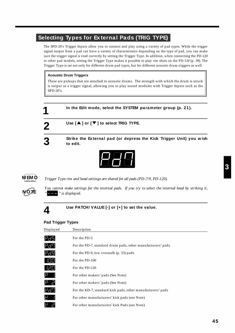
Selecting Types for External Pads (TRIG TYPE)The SPD-20’s Trigger Inputs allow you to connect and play using a variety of pad types. While the triggersignal output from a pad can have a variety of characteristics depending on the type of pad, you can makesure the trigger signal is read correctly by setting the Trigger Type. In addition, when connecting the PD-120or other pad models, setting the Trigger Type makes it possible to play rim shots on the PD-120 (p. 39). TheTrigger Type is set not only for different drum pad types, but for different acoustic drum triggers as well.
1 In the Edit mode, select the SYSTEM parameter group (p. 21).
2 Use [ ] or [ ] to select TRIG TYPE.
3 Strike the External pad (or depress the Kick Trigger Unit) you wishto edit.
fig.53
Trigger Type rim and head settings are shared for all pads (PD-7/9, PD-120).
You cannot make settings for the internal pads. If you try to select the internal head by striking it,“ ” is displayed.
4 Use PATCH/VALUE [-] or [+] to set the value.
Pad Trigger Types
Displayed Descriptionfig.54
For the PD-5
For the PD-7, standard drum pads, other manufacturers’ pads
For the PD-9, low crosstalk (p. 53) pads
For the PD-100
For the PD-120
For other makers’ pads (See Note)
For other makers’ pads (See Note)
For the KD-7, standard kick pads, other manufacturers’ pads
For other manufacturers’ kick pads (see Note)
For other manufacturers’ kick Pads (see Note)
Acoustic Drum Triggers
These are pickups that are attached to acoustic drums. The strength with which the drum is struckis output as a trigger signal, allowing you to play sound modules with Trigger Inputs such as theSPD-20’s.
MEMO
NOTE
45
1
2
3
4
5

(Note) This type of Trigger (TRIG TYPE) is for drum pads whose output of the Trigger signal wave-form’s attack is slow. In order to reliably detect the strength with which the pad is struck, thetime set for detection of the trigger (Scan Time; p. 51) is as slow as 1–2 msec. When using othermanufacturers’ pads, if while playing with the Trigger Type set to “Pd7” you notice the soundstrength or dynamics are unstable, you should reset the Trigger Type to “P1” or “P2.”
For faster sound expression, set to “P1” or “P2” (“K1” or “K2”).
Acoustic Drum Trigger Types
Displayed Descriptionfig.54
For kick drums (bass drums)
For snare drums
For toms
For floor toms, toms with 15-inch or bigger heads
Trigger Type Internal Settings (Advanced TRIGGER Parameters)
When you make settings for the Trigger Type, a number of internal parameters that do not appearon the panel are set automatically. These parameters are known as Advanced TRIGGER parame-ters. Normally, no detailed settings are necessary to match the selected Trigger Type, but whenyou get poor sound, even having set the Trigger Type, or when using pads or acoustic drum trig-gers not covered by a particular Trigger Type, then set the Advanced TRIGGER parameters asneeded (p. 48).
Advanced TRIGGER Parameter Description
Scan Time Sets the time for detecting the trigger signal
Retrigger Cancel Detects the attenuation of the trigger signal and cancels subse-quent incorrect triggering
Mask Time Cancels secondary sounding of the kick pad and other pads
Crosstalk Cancel Cancels triggering caused by vibration from other pads
Rim Sensitivity Adjusts the PD-120’s Rim Sensitivity
For more detailed information, refer to (p. 48).
46
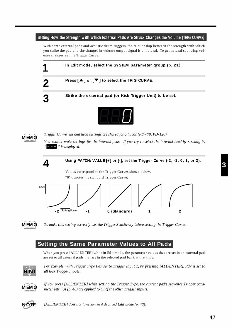
Setting How the Strength with Which External Pads Are Struck Changes the Volume (TRIG CURVE)
With some external pads and acoustic drum triggers, the relationship between the strength with whichyou strike the pad and the changes in volume output signal is unnatural. To get natural-sounding vol-ume changes, set the Trigger Curve.
1 In Edit mode, select the SYSTEM parameter group (p. 21).
2 Press [ ] or [ ] to select the TRIG CURVE.
3 Strike the external pad (or Kick Trigger Unit) to be set.
fig. 55
Trigger Curve rim and head settings are shared for all pads (PD-7/9, PD-120).
You cannot make settings for the internal pads. If you try to select the internal head by striking it,“ ” is displayed.
4 Using PATCH/VALUE [+] or [-], set the Trigger Curve (-2, -1, 0, 1, or 2).
Values correspond to the Trigger Curves shown below.
“0” denotes the standard Trigger Curve.fig. 56
To make this setting correctly, set the Trigger Sensitivity before setting the Trigger Curve.
Setting the Same Parameter Values to All PadsWhen you press [ALL/ENTER] while in Edit mode, the parameter values that are set in an external padare set to all external pads that are in the selected pad bank at that time.
For example, with Trigger Type Pd7 set to Trigger Input 1, by pressing [ALL/ENTER], Pd7 is set toall four Trigger Inputs.
If you press [ALL/ENTER] when setting the Trigger Type, the current pad’s Advance Trigger para-meter settings (p. 48) are applied to all of the other Trigger Inputs.
[ALL/ENTER] does not function in Advanced Edit mode (p. 48).
MEMO
0 (Standard)-2 -1 1 2
Level
Striking Force
MEMO
MEMO
NOTE
47
1
2
3
4
5
Setting Parameters for Reliable Performance using Acoustic DrumTriggers and Other Manufacturers’ Pads (Advanced Trigger Parameters)
Sometimes, when you use the SPD-20 with an acoustic drum trigger or a pad from another manufacturer,setting only the Trigger Type may result in poor sound or mistakenly played sounds. In such cases, by set-ting the Advanced Trigger Parameters, you can make more detailed trigger parameter settings.
Advanced Trigger Parameters are set automatically when the Trigger Type is set. Normally, whenyou set the Trigger Type, no setting of the Advanced Trigger Parameters is necessary.
The five Advanced Trigger Parameters are as follows:
Scan Time Sets the time for detecting the trigger signal
Retrigger Cancel Detects the attenuation of the trigger signal, and prevents subsequentincorrect triggering
Mask Time Prevents secondary sounding of the kick pad and other pads
Crosstalk Cancel Prevents triggering caused by vibration from other pads
Rim Sensitivity Adjusts the sensitivity of the PD-120´s rim
How to Set Advanced Trigger ParametersThe process of making settings for the Advanced Trigger Parameters differs from that when makingother settings. Special procedures are required to set the parameters in Advanced Edit mode.
The Advanced Trigger Parameters cannot be found in the Parameter List on the front panel.
You cannot make Advanced Trigger Parameter settings for internal pads.
First, set the Trigger Type. When you set the Trigger Type, the most suitable Advanced TriggerParameters values are set automatically.
If, after having set the Advanced Trigger Parameters, you then change the Trigger Type setting, theAdvanced Trigger Parameter settings revert to the initial values for that Trigger Type.
1 In Edit mode, select the SYSTEM parameter group (p. 21).
2 Press [ ] or [ ] to select the TRIG TYPE.
3 Strike the external pad (or drum pad) to be set.
fig. 57
NOTE
NOTE
There are three modes
Play mode: The unit is played in this mode.
Edit mode: Status in which settings are made for the parameters from the parameterlist.
Advanced Edit mode: In this mode, settings can be made for the Advanced Trigger Parameters,which are not included in the parameter list.
NOTE
48

Trigger Type rim and head settings are shared for all pads (PD-7/9, PD-120).
You cannot make settings for the internal pads. If you try to select the internal head by striking it,“ ” is displayed.
4 Using PATCH/VALUE [+] or [-], set the Trigger Type.
If you don’t find the settings most suitable for your Trigger Type, then set the type youthink is closest.
Drum Pad: Pd7, P 1, P 2
Kick Pad: Kd7, K 1, K 2
Acoustic Drum Trigger: KiK, Snr, toM, FLr
For descriptions of each of the Trigger Types, see p. 45.
Up to this point, the procedure has been the same as in making normal Trigger Type set-tings.
After setting the Trigger Type, the following operation is used to enter Advanced Editmode.
5 Confirm that Trigger Type (TRIG TYPE) in the SYSTEM parametergroup has been selected.
6 Hold down [EDIT] for several seconds. This takes you intoAdvanced Edit mode.
fig. 58
In Advanced Edit mode, the SYSTEM Parameter Group indicator flashes.
One second after “Scn” appears in the display, the value is then displayed.fig.59
This is the Scan Time settings screen.
If the TRIG TYPE settings screen does not come up, consequently, you can not call up the AdvancedEdit Mode screens by holding down [EDIT].
MEMO
MEMO
(Flashing)
MEMO
About one second later
NOTE
49
1
2
3
4
5
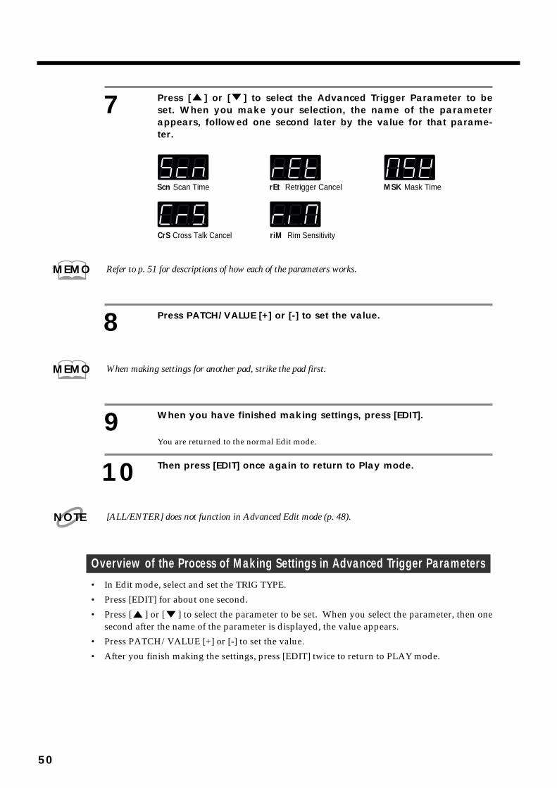
7 Press [ ] or [ ] to select the Advanced Trigger Parameter to beset. When you make your selection, the name of the parameterappears, followed one second later by the value for that parame-ter.
fig. 60
Refer to p. 51 for descriptions of how each of the parameters works.
8 Press PATCH/VALUE [+] or [-] to set the value.
When making settings for another pad, strike the pad first.
9 When you have finished making settings, press [EDIT].
You are returned to the normal Edit mode.
10 Then press [EDIT] once again to return to Play mode.
[ALL/ENTER] does not function in Advanced Edit mode (p. 48).
Overview of the Process of Making Settings in Advanced Trigger Parameters• In Edit mode, select and set the TRIG TYPE.
• Press [EDIT] for about one second.
• Press [ ] or [ ] to select the parameter to be set. When you select the parameter, then onesecond after the name of the parameter is displayed, the value appears.
• Press PATCH/VALUE [+] or [-] to set the value.
• After you finish making the settings, press [EDIT] twice to return to PLAY mode.
Scn Scan Time rEt Retrigger Cancel MSK Mask Time
CrS Cross Talk Cancel riM Rim Sensitivity
MEMO
MEMO
NOTE
50
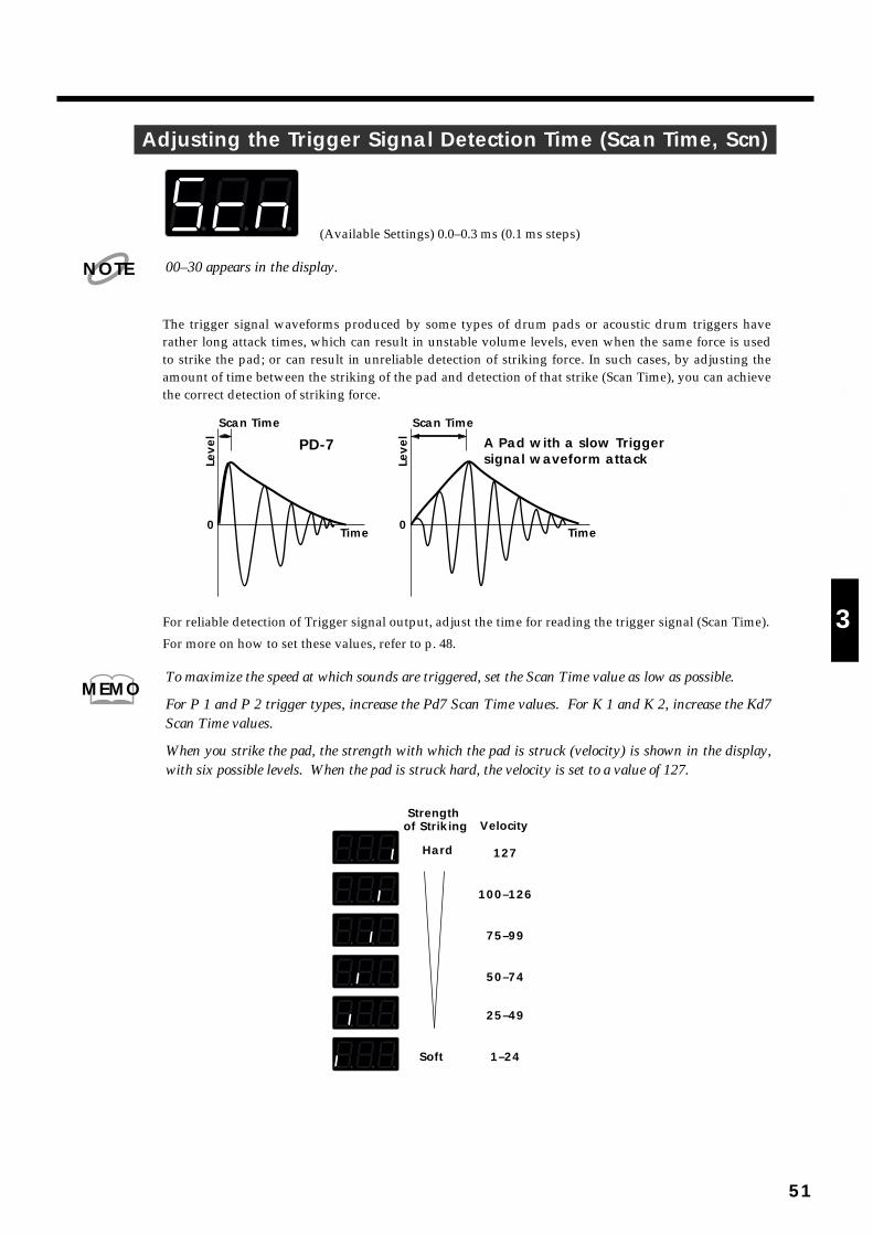
Adjusting the Trigger Signal Detection Time (Scan Time, Scn)fig.60-a
(Available Settings) 0.0–0.3 ms (0.1 ms steps)
00–30 appears in the display.
The trigger signal waveforms produced by some types of drum pads or acoustic drum triggers haverather long attack times, which can result in unstable volume levels, even when the same force is usedto strike the pad; or can result in unreliable detection of striking force. In such cases, by adjusting theamount of time between the striking of the pad and detection of that strike (Scan Time), you can achievethe correct detection of striking force.
fig.60-b
For reliable detection of Trigger signal output, adjust the time for reading the trigger signal (Scan Time).
For more on how to set these values, refer to p. 48.
To maximize the speed at which sounds are triggered, set the Scan Time value as low as possible.
For P 1 and P 2 trigger types, increase the Pd7 Scan Time values. For K 1 and K 2, increase the Kd7Scan Time values.
When you strike the pad, the strength with which the pad is struck (velocity) is shown in the display,with six possible levels. When the pad is struck hard, the velocity is set to a value of 127.
fig.95
NOTE
Scan TimeScan Time
A Pad with a slow Trigger signal waveform attack
PD-7
00Time
Leve
l
Time
Leve
l
MEMO
VelocityStrength
of Striking
Hard 127
100–126
75–99
50–74
25–49
1–24Soft
51
1
2
3
4
5
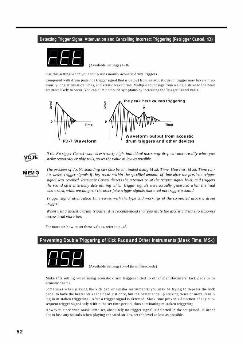
Detecting Trigger Signal Attenuation and Cancelling Incorrect Triggering (Retrigger Cancel, rEt)fig.60-c
(Available Settings) 1–16
Use this setting when your setup uses mainly acoustic drum triggers.
Compared with drum pads, the trigger signal that is output from an acoustic drum trigger may have unnec-essarily long attenuation times, and erratic waveforms. Multiple soundings from a single strike to the headare more likely to occur. You can eliminate such symptoms by increasing the Trigger Cancel value.
fig.61
If the Retrigger Cancel value is extremely high, individual notes may drop out more readily when youstrike repeatedly or play rolls, so set the value as low as possible.
The problem of double sounding can also be eliminated using Mask Time. However, Mask Time can-not detect trigger signals if they occur within the specified amount of time after the previous triggersignal was received. Retrigger Cancel detects the attenuation of the trigger signal level, and triggersthe sound after internally determining which trigger signals were actually generated when the headwas struck, while weeding out the other false trigger signals that need not trigger a sound.
Trigger signal attenuation time varies with the type and workings of the connected acoustic drumtrigger.
When using acoustic drum triggers, it is recommended that you mute the acoustic drums to suppressexcess head vibration.
For more on how to set these values, refer to p. 48.
Preventing Double Triggering of Kick Pads and Other Instruments (Mask Time, MSk)fig.61-a
(Available Settings) 0–64 (in milliseconds)
Make this setting when using acoustic drum triggers fitted to other manufacturers’ kick pads or toacoustic drums.
Sometimes when playing the kick pad or similar instruments, you may be trying to depress the kickpedal to have the beater strike the head just once, but the beater ends up striking twice or more, result-ing in mistaken triggering. After a trigger signal is detected, Mask time prevents detection of any sub-sequent trigger signal only within the set time period, thus eliminating mistaken triggering.
However, since with Mask Time set, absolutely no trigger signal is detected in the set period, in ordernot to lose any sounds when playing repeated strikes, set the level as low as possible.
PD-7 WaveformWaveform output from acoustic drum triggers and other devices
The peak here causes triggering
00Time
Leve
l
Time
Leve
l
NOTE
MEMO
52
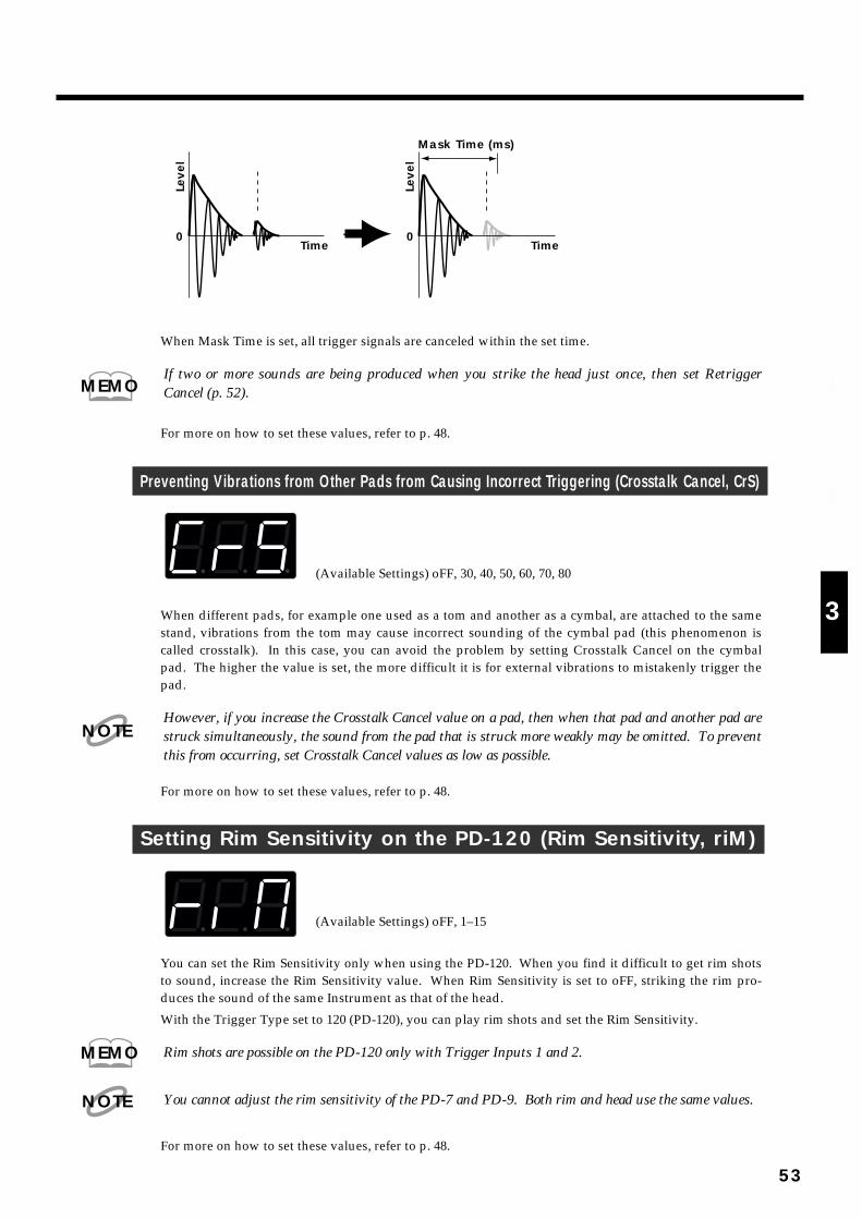
fig.62
When Mask Time is set, all trigger signals are canceled within the set time.
If two or more sounds are being produced when you strike the head just once, then set RetriggerCancel (p. 52).
For more on how to set these values, refer to p. 48.
Preventing Vibrations from Other Pads from Causing Incorrect Triggering (Crosstalk Cancel, CrS)fig.62-a
(Available Settings) oFF, 30, 40, 50, 60, 70, 80
When different pads, for example one used as a tom and another as a cymbal, are attached to the samestand, vibrations from the tom may cause incorrect sounding of the cymbal pad (this phenomenon iscalled crosstalk). In this case, you can avoid the problem by setting Crosstalk Cancel on the cymbalpad. The higher the value is set, the more difficult it is for external vibrations to mistakenly trigger thepad.
However, if you increase the Crosstalk Cancel value on a pad, then when that pad and another pad arestruck simultaneously, the sound from the pad that is struck more weakly may be omitted. To preventthis from occurring, set Crosstalk Cancel values as low as possible.
For more on how to set these values, refer to p. 48.
Setting Rim Sensitivity on the PD-120 (Rim Sensitivity, riM)fig.62-b
(Available Settings) oFF, 1–15
You can set the Rim Sensitivity only when using the PD-120. When you find it difficult to get rim shotsto sound, increase the Rim Sensitivity value. When Rim Sensitivity is set to oFF, striking the rim pro-duces the sound of the same Instrument as that of the head.
With the Trigger Type set to 120 (PD-120), you can play rim shots and set the Rim Sensitivity.
Rim shots are possible on the PD-120 only with Trigger Inputs 1 and 2.
You cannot adjust the rim sensitivity of the PD-7 and PD-9. Both rim and head use the same values.
For more on how to set these values, refer to p. 48.
Time Time
Leve
l
Leve
l
0 0
Mask Time (ms)
MEMO
NOTE
MEMO
NOTE
53
1
2
3
4
5

Settings for an External Hi-Hat Control PedalYou can use the hi-hat control pedal (FD-7; sold separately) not only to open and close the hi-hat, youcan also use it to control the sound effect level sent in real time, and change the pitch (PDL CTRL; p. 54).Additionally, you can send Control Change Data to connected external MIDI devices (PDL CC#; p. 56).
Hi-Hat Control pedal settings are made with FX/PEDAL Parameter Group PDL CTRL, PDL LEVEL,and PDL CC#. Too see how to make these settings, refer to each item shown on the following page.
For more on how to connect the pedal, refer to “Precautions When Connecting a Hi-Hat ControlPedal” (p. 40).
Hi-Hat control pedal settings are stored in each Patch.
Controlling the Tone with the Hi-Hat Control Pedal—PedalControl (PDL CTRL)
Select from the following settings to determine how the hi-hat control pedal exerts control whenpressed.
HH Opened/closed hi-hat sounds (p. 54)
EFS Tone Effect Send (p. 55)
U07, U12, U24, d05, d12, d24 Raising and lowering of the pitch (p. 55)
1 In the Edit mode, select the FX/PEDAL parameter group.
2 Use [ ] or [ ] to select PDL CTRL.
3 Use PATCH/VALUE [-] or [+] to select the function you wish to con-trol.
You can make settings for each Patch independently.
Controlling the Opening and Closing of the Hi-Hat (HH)The pedal works as a hi-hat control pedal controlling sounds (H01–H17) assigned to a pad. Stepping onthe pedal while striking the pad produces a closed hi-hat sound, and by letting up on the pedal a little ata time, you continuously change the tone and length of the sound from closed, to half-opened, toopened. Additionally, you can get a “foot close” sound by stepping on the pedal more forcefully. Youcan also get a great “foot open” sound, similar to the sound you get as you lift your foot off the hi-hat.
Set the volume of the pedal hi-hat sound produced with the pedal in PDL LEVEL. For more on how tomake these settings, refer to “Adjustivg the Volume of the Pedal Hi-Hat Sound” (p. 55).
If a hi-hat sound (H01–H17) is assigned to two or more pads, the pedal hi-hat will sound for the high-est-priority pad as shown in next page:
MEMO
MEMO
MEMO
NOTE
54

The Velocity Curve (p. 24) and layer (p. 17) settings do not affect the pedal hi-hat sound.
Control the effect applied to an Instrument (EFS)When this function is assigned, the hi-hat control pedal will control the effect send level of anInstrument. When the pedal is released, the pad takes the values set for the pad (values set in FXSEND). When the pedal is depressed, the effect send level will be increased proportionally to the angleof the pedal.
Control Instrument pitch (U07/U12/U24/d05/d12/d24)When this function is assigned, the hi-hat control pedal will control the pitch of an Instrument. Whenthe pedal is released, the pad takes the pitch set for the pad. When the pedal is depressed, the pitch willbe modified proportionally to the angle of the pedal.
U07 up 700 cents (a perfect fifth)
U12 up 1,200 cents (one octave)
U24 up 2,400 cents (two octaves)
d05 down 500 cents (a perfect fourth)
d12 down 1,200 cents (one octave)
d24 down 2,400 cents (two octaves)
Depending on the type of Instrument or on the sound parameter pitch settings, there may be a pointabove which the pitch cannot be raised.
Adjusting the Volume of the Pedal Hi-Hat Sound (PDL LEVEL)When one of the Hi-Hat Cymbals for pedal control (H01–H17) sounds is assigned to the pad, you cancontrol the pedal hi-hat volume when the hi-hat control pedal is pressed. Higher values will result in alouder sound. At a setting of 0, there will be no sound.
1 In the Edit mode, select the FX/PEDAL parameter group.
2 Use [ ] or [ ] to select PDL LEVEL.
3 Use PATCH/VALUE [-] or [+] to set the volume (0–15).
INT1 INT2 INT3 INT4 INT5 INT6 INT7 INT8
TRIG1 TRIG2 TRIG3 TRIG4 TRIG1 TRIG2 TRIG3 TRIG4
TRIG1 TRIG2 TRIG3 TRIG4 TRIG1 TRIG2 TRIG3 TRIG4
(Head) (Head) (Head) (Head) (Rim) (Rim) (Rim) (Rim)
INT1 INT2 INT3 INT4 INT5 INT6 INT7 INT8
(Head) (Head) (Head) (Head) (Rim) (Rim) (Rim) (Rim)
Pad Bank A
Pad Bank B
high priority
low priorityINT 1: Internal pad 1TRIG 1: Trigger input 1
NOTE
NOTE
55
1
2
3
4
5
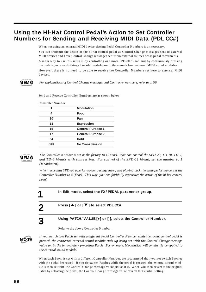
Using the Hi-Hat Control Pedal’s Action to Set ControllerNumbers for Sending and Receiving MIDI Data (PDL CC#)
When not using an external MIDI device, Setting Pedal Controller Numbers is unnecessary.
You can transmit the action of the hi-hat control pedal as Control Change messages sent to externalMIDI devices and have Control Change messages sent from external sources act as pedal movements.
A main way to use this setup is by controlling one more SPD-20 hi-hat, and by continuously pressingthe pedals, you can do things like add modulation to the sounds from external MIDI sound modules.
However, there is no need to be able to receive the Controller Numbers set here to external MIDIdevices.
For explanations of Control Change messages and Controller numbers, refer to p. 59.
Send and Receive Controller Numbers are as shown below.
Controller Number
1 Modulation
4 Foot
10 Pan
11 Expression
16 General Purpose 1
17 General Purpose 2
64 Hold
oFF No Transmission
The Controller Number is set at the factory to 4 (Foot). You can control the SPD-20, TD-10, TD-7,and TD-5 hi-hats with this setting. For control of the SPD-11 hi-hat, set the number to 1(Modulation).
When recording SPD-20 a performance to a sequencer, and playing back the same performance, set theController Number to 4 (Foot). This way, you can faithfully reproduce the action of the hi-hat controlpedal.
1 In Edit mode, select the FX/PEDAL parameter group.
2 Press [ ] or [ ] to select PDL CC#.
3 Using PATCH/VALUE [+] or [-], select the Controller Number.
Refer to the above Controller Number.
If you switch to a Patch set with a different Pedal Controller Number while the hi-hat control pedal ispressed, the connected external sound module ends up being set with the Control Change messagevalue set in the immediately preceding Patch. For example, Modulation will constantly be applied tothe external sound module.
When each Patch is set with a different Controller Number, we recommend that you not switch Patcheswith the pedal depressed. If you do switch Patches while the pedal is pressed, the external sound mod-ule is then set with the Control Change message value just as it is. When you then revert to the originalPatch by releasing the pedal, the Control Change message value reverts to its initial setting.
MEMO
MEMO
NOTE
56

MIDI ConnectionsWhen connected to other MIDI devices, the SPD-20 can be used in a wide variety of musically creativeways. For example, it can be connected to a sequencer as a pad controller for realtime input, and its on-board sound generator can be layered with external sound modules. Other applications include using asequencer to automatically select SPD-20 Patches, or to store SPD-20 data in a sequencer or other MIDIBulk storage device.
Example of one way to connect when using the SPD-20 to control an external soundmodule
fig.64
About MIDIMIDI is an acronym for “Musical Instrument Digital Interface,” and is a standard by which electronicmusical Instruments and computers can exchange musical data. The SPD-20 conforms to the MIDI spec-ification and can be connected to other devices to either control, or be controlled.
How MIDI Data is Sent and ReceivedFirst, we will briefly explain how MIDI data is sent and received.
MIDI connectorsMIDI data is sent and received through the following connectors. Use a MIDI cable to connectors theseconnectors to other devices.
fig.65
MIDI IN: receives data from other MIDI devices
MIDI OUT: transmits data to other MIDI devices
MIDI THRU: re-transmits the data received via MIDI IN
The SPD-20 does not have a MIDI THRU connector.
It is possible to connect (“daisy chain”) several MIDI devicesusing the MIDI THRU connectors, but you should keep thetotal length of MIDI cables within 10 meters, to prevent possiblereception errors.
AC adaptor
L I N E I NL R
Audio Equipment(Stereo Set)
Sampler
SPD-20
MIDI IN
MIDI OUT
NOTE
CHAPTER 4 Connecting MIDI Devices
57
1
2
3
4
5
MIDI channelsMIDI allows you to independently control two or more devices over a single MIDI cable. This is possi-ble because MIDI provides for multiple channels of control. You can think of MIDI channels as beingsimilar to television channels. Although many broadcast channels are in the air at any one time (manychannels of MIDI data are moving through a single cable), a television set receives only the channel towhich it is set (the MIDI device receives only the channel to which it is set).
fig.66
MIDI provides sixteen channels, 1–16, and the receiving device will only receive data when its receivechannel matches the Transmit Channel. In the following diagram, playing the keyboard will cause onlysound module B to play.
fig.67
With the SPD-20, you can set the Transmit Channel (TX CH) for each pad (p. 61). Settings for thereceiving end are made with the Basic Channel (BASIC CH) (p. 67).
Main Types of MIDI Data Used by the SPD-20A wide variety of musical data can be transmitted by MIDI, with a different type of MIDI message pro-vided for each type of data. MIDI messages can be broadly categorized into two groups: informationthat is differentiated by channel (Channel messages) and information that is not differentiated by chan-nel (System messages).
Data differentiated by channel (Channel messages)These messages carry musical performance data. Normally, these messages do most of the work. Theresult that each type of message produces will depend on the settings of the sound module.
•
Note messagesThese messages notify the sound generator that a pad has been struck. (A keyboard would transmitthese messages when keys are played.) Note messages convey the following information.
Note Number: Each note message (Note On or Note Off) carries the Note Number which wasassigned to that pad (a number indicating the note position on a keyboard).
Note On: This message is transmitted when a pad is struck (when a key is played).
Note Off: This message is transmitted when the specified Gate Time has elapsed after the NoteOn message (when a key is released).
Velocity: Each note message contains data indicating how strongly the pad was struck (howstrongly the key was played).
TV Station A
TV Station B
TV Station C
TV messages from various TV Stations are sent through the antenna’s cable.
Select the channel of the TV Station you wish to watch.
MIDI OUT MIDI IN MIDI THRU
MIDI INTransmit channel: 1
Receive channel: 2
Receive channel: 1
Sound Module A
Sound Module B
MEMO
58
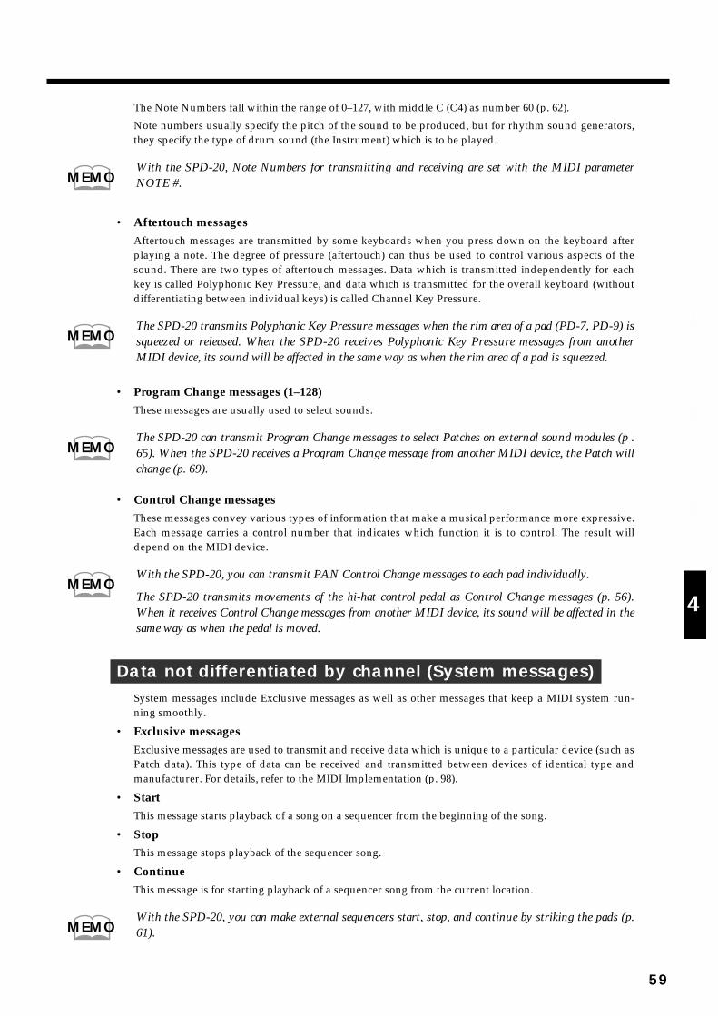
The Note Numbers fall within the range of 0–127, with middle C (C4) as number 60 (p. 62).
Note numbers usually specify the pitch of the sound to be produced, but for rhythm sound generators,they specify the type of drum sound (the Instrument) which is to be played.
With the SPD-20, Note Numbers for transmitting and receiving are set with the MIDI parameterNOTE #.
• Aftertouch messagesAftertouch messages are transmitted by some keyboards when you press down on the keyboard afterplaying a note. The degree of pressure (aftertouch) can thus be used to control various aspects of thesound. There are two types of aftertouch messages. Data which is transmitted independently for eachkey is called Polyphonic Key Pressure, and data which is transmitted for the overall keyboard (withoutdifferentiating between individual keys) is called Channel Key Pressure.
The SPD-20 transmits Polyphonic Key Pressure messages when the rim area of a pad (PD-7, PD-9) issqueezed or released. When the SPD-20 receives Polyphonic Key Pressure messages from anotherMIDI device, its sound will be affected in the same way as when the rim area of a pad is squeezed.
• Program Change messages (1–128)These messages are usually used to select sounds.
The SPD-20 can transmit Program Change messages to select Patches on external sound modules (p .65). When the SPD-20 receives a Program Change message from another MIDI device, the Patch willchange (p. 69).
• Control Change messagesThese messages convey various types of information that make a musical performance more expressive.Each message carries a control number that indicates which function it is to control. The result willdepend on the MIDI device.
With the SPD-20, you can transmit PAN Control Change messages to each pad individually.
The SPD-20 transmits movements of the hi-hat control pedal as Control Change messages (p. 56).When it receives Control Change messages from another MIDI device, its sound will be affected in thesame way as when the pedal is moved.
Data not differentiated by channel (System messages)System messages include Exclusive messages as well as other messages that keep a MIDI system run-ning smoothly.
• Exclusive messagesExclusive messages are used to transmit and receive data which is unique to a particular device (such asPatch data). This type of data can be received and transmitted between devices of identical type andmanufacturer. For details, refer to the MIDI Implementation (p. 98).
• StartThis message starts playback of a song on a sequencer from the beginning of the song.
• StopThis message stops playback of the sequencer song.
• ContinueThis message is for starting playback of a sequencer song from the current location.
With the SPD-20, you can make external sequencers start, stop, and continue by striking the pads (p.61).
MEMO
MEMO
MEMO
MEMO
MEMO
59
1
2
3
4
5

• Song Position PointThis message tell the connected sequencer to move the current location in the song.
With the SPD-20, you can return to the first measure of a sequencer song by striking the pad (p. 61).
• Active sensingThese messages are used to monitor the integrity of MIDI connections. If no MIDI messages arereceived within a specific length of time, the device assumes that the connection has been broken (e.g., acable disconnected) and will reset itself according to a specific procedure.
How to Read the MIDI Implementation ChartMIDI has made it possible for a wide variety of devices to exchange information, but it is not alwaystrue that all types of MIDI messages can be exchanged between all types of devices.
To help you quickly determine what types of MIDI messages can be exchanged between master andslave, the manual of each MIDI device includes a MIDI Implementation chart. By looking at this chart,you can quickly see what messages the device is able to transmit and receive. MIDI Implementationcharts are standardized, so you can fold the charts together to see at a glance how the two devices willcommunicate.
fig.68
A MIDI Implementation chart for the SPD-20 is included in page 102 .
MEMO
Function Transmitted Recognized Remarks
MIDI ImplementationChart for the receiver
MIDI ImplementationChart for the transmitter
MEMO
60

MIDI Parameter SettingsIf you wish to use the SPD-20 to control another MIDI sound module, or use another MIDI device tocontrol the SPD-20, you will need to set the MIDI parameters.
You can set MIDI parameters for each pad in a pad bank (A and B), allowing you to control externalsound modules on two channels. Additionally, MIDI parameters can be set to Patches.
For more on how to set MIDI parameters, refer to p. 66.
How the MIDI Parameters Work
Transmit Channel (TX CH)Set this parameter to match the receive channel of the MIDI sound module you have connected. If youwant a pad to play only the SPD-20’s sounds, set this parameter to “oFF.”
Besides the Transmit Channel, settings for transmitting Program Numbers by striking the pad, and fortransmitting Start and Stop messages to external sequencers are also made in the TX CH settings.
Using the Pads to Play External Sound Modules
1–16: When playing external sound modules, Note messages are sent through the TransmitChannels set here. If you find it unnecessary to make any special setting for this, just set it to10 (the initial value).
If you switch Patches while setting Program Changes (PGM CHG; p. 65), the Program Number issent through the TX CH (1–16) set here.
When You Are Not Sending MIDI Messages
oFF: MIDI messages are not transmitted.
Using the Pads to Control External Devices
With these settings Note messages are not transmitted.
P1–P16: Set this when using the pad to switch external sound module tones. The Program Numberset to Program Change (PGM CHG; p. 65) is sent via the MIDI channel 1–16 (P1–P16) accord-ing to the timing with which you strike the pad.
S-S: Controls external sequencers and other devices by mutual transmission of MIDI Start andStop messages when the Pad is struck.
C-S: Controls external sequencers and other devices by mutual transmission of MIDI Continueand Stop messages when the pad is struck.
toP: Returns the external sequencer’s Song Position to the first measure of the song.
External sound modules cannot be played when you set oFF, P1–P16, S-S, C-S, or toP, since the NoteNumbers are not transmitted. Pads set with these parameters are dedicated pads for controlling exter-nal sound modules or external MIDI devices.
MEMO
MEMO
NOTE
61
1
2
3
4
5
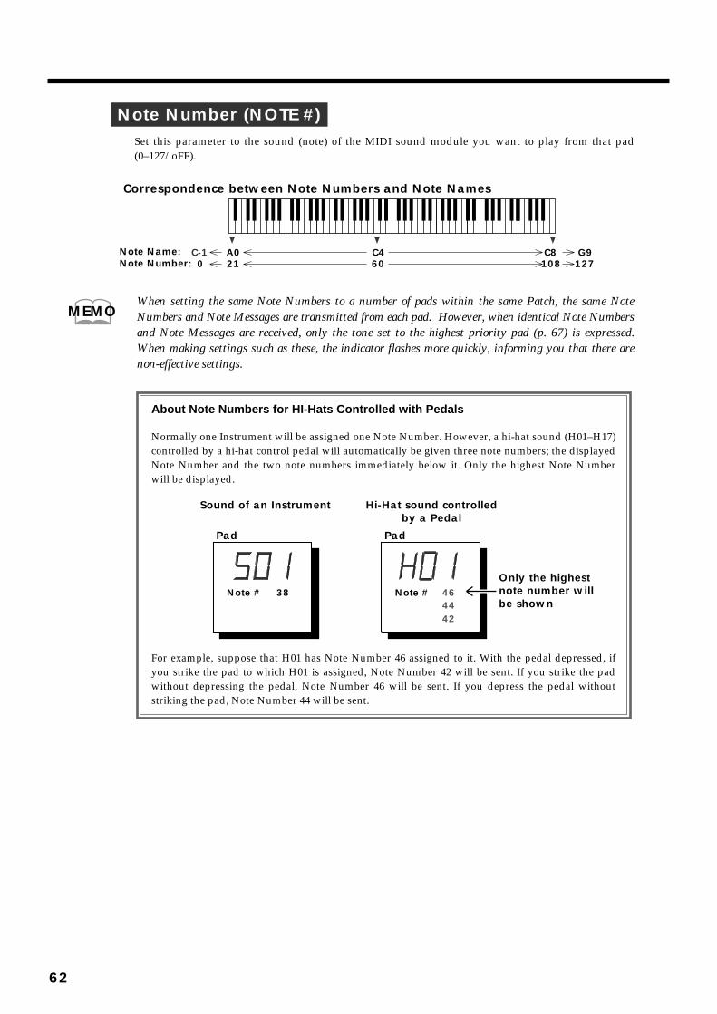
Note Number (NOTE #)Set this parameter to the sound (note) of the MIDI sound module you want to play from that pad(0–127/oFF).
fig.69
When setting the same Note Numbers to a number of pads within the same Patch, the same NoteNumbers and Note Messages are transmitted from each pad. However, when identical Note Numbersand Note Messages are received, only the tone set to the highest priority pad (p. 67) is expressed.When making settings such as these, the indicator flashes more quickly, informing you that there arenon-effective settings.
fig.70
A0 C4 C821 60 108
C-10
G9127
Correspondence between Note Numbers and Note Names
Note Name:Note Number:
MEMO
Note #
Pad
Note #
Pad
4446
42
Sound of an Instrument Hi-Hat sound controlledby a Pedal
Only the highestnote number willbe shown
About Note Numbers for HI-Hats Controlled with Pedals
Normally one Instrument will be assigned one Note Number. However, a hi-hat sound (H01–H17) controlled by a hi-hat control pedal will automatically be given three note numbers; the displayed Note Number and the two note numbers immediately below it. Only the highest Note Number will be displayed.
For example, suppose that H01 has Note Number 46 assigned to it. With the pedal depressed, if you strike the pad to which H01 is assigned, Note Number 42 will be sent. If you strike the pad without depressing the pedal, Note Number 46 will be sent. If you depress the pedal without striking the pad, Note Number 44 will be sent.
38
62

Gate Time (GT TIME)This parameter determines the length of time that the MIDI sound module will produce sound (0.1 sec-ond–4.0 seconds, ALt).
Settings values shown in the display are 01–40 and ALt (0.1–4.0 seconds and Alternate).
fig.71
This Gate Time parameter corresponds to the length of time a note is held (on a MIDI keyboard) beforeit is released.
When you set “ALt”, Note On and Note Off are alternately transmitted when you strike the pad. Whenusing samplers and other such devices, you can strike a pad to start a sampler phrase loop, and stop thephrase loop the next you strike the same pad.
If the MIDI sound module ignores Note Off messages, this Gate Time parameter will not affect thelength of the note (Drum sound modules and other sound modules).
The actual length of time the note sounds will depend on the settings of the MIDI sound module.
If you are using a pad to play a sound that has a slow attack, the note may be too quiet or may be cutoff too quickly. If so, increase the Gate Time.
Pan (PAN)If you have connected a MIDI sound module that can receive Pan Control Change messages (controlnumber 10), this parameter allows you to specify the stereo position (L7–Ctr–r7/rnd/oFF). With a set-ting of “rnd” the stereo position will change randomly each time you strike the pad. With a setting of“oFF,” Pan messages will not be transmitted.
fig.72
If the MIDI sound module ignores Pan Control Change messages (control number 10), this Pan para-meter will not affect the stereo position.
NOTE
Gate time Time
Volu
me
NOTE
MEMO
Right SpeakerLeft Speaker
Ctr(Center)
L7 r7
NOTE
63
1
2
3
4
5

MIDI Velocity Curve (CURVE)When changing the strength with which you strike the pad, select from the following 16 types of veloci-ty curves for transmitting Velocity values (volume changes) from MIDI OUT.
fig.73
If this parameter is set to “CSt” (constant), the volume will be the same for each note—regardless ofhow strongly or softly you strike the pad. In this case, you will adjust the velocity Sensitivity parameterto set the volume.
Velocity Sensitivity (SENS)When striking the pad, you can adjust the Velocity Sensitivity (1–15) transmitted to a MIDI device.Sensitivity increases as the value is raised, allowing you to transmit high Velocity levels even whenstriking the pad softly.
If the Velocity Curve parameter has been set to “CSt,” velocity will be transmitted with the followingvalue.
fig.74
Exponent ia l 1 Exponent ia l 2 Exponent ia l 3 Linear
Spl ine 1 Soft 1Exponent ia l 4 Spl ine 2
Hard 1Soft 4
Hard 3 ConstantHard 2 Hard 4
Soft 2 Soft 3
Sensitivity Velocity Sensitivity Velocity1
2
3
4
5
6
7
8
1
10
19
28
37
46
55
64
9
10
11
12
13
14
15
73
82
91
100
109
118
127
64

Program Change (PGM CHG)By transmitting Program Change messages, the SPD-20 can select sounds on another MIDI device. Thisparameter specifies the Program Number transmitted when Patches are switched (1–128, oFF). In theEdit mode, each time you modify this parameter, a Program Change message will be transmitted imme-diately from MIDI OUT, so that you can then strike the pad to check the external sound module. If youdo not wish to transmit Program Change messages, set this parameter to “oFF.”
Each Pad will transmit a Program Change message on its assigned MIDI channel whenever a Patch isselected in the Play mode. If two or more pads are assigned to the same MIDI channel and have been setto transmit different Program Numbers, only the highest-priority pad will transmit the ProgramChange (p. 67).
If while editing you attempt to make such a conflicting setting, the display will flash more rapidly towarn you. Also, Program Change messages for the lowest-priority pad will not be transmitted fromthe conflicting pad.
When transmitting Program Numbers set with Program Change (PGM CHG) by striking the pad, setthe Transmit Channel (TX CH) to (P 1–P16) (p. 61). However, Note Numbers from a pad set like thisare not transmitted, so you cannot use them to play an external sound module.
fig.75
MEMO
NOTE
11
2
2
3
3
4
4
5
5
6
6
7
7
81 2 3 4 5 6 7 89 10 11 12 13 14 15 1617 18 19 20 21 22 23 2425 26 27 28 29 30 31 3233 34 35 36 37 38 39 4041 42 43 44 45 46 47 4849 50 51 52 53 54 55 5657 58 59 60 61 62 63 648
Ban
k
NumberGroup A
11
2
2
3
3
4
4
5
5
6
6
7
7
865 66 67 68 69 70 71 7273 74 75 76 77 78 79 8081 82 83 84 85 86 87 8889 90 91 92 93 94 95 9697 98 99 100 101 102 103 104105 106 107 108 109 110 111 112113 114 115 116 117 118 119 120121 122 123 124 125 126 127 1288
Ban
k
NumberGroup B
The following table shows how the numeric display (1–128) corresponds to the GBN (Group/Bank/Number) Program Number scheme used in Roland devices.
GBN systemThis is a way of organizing Patch memory select buttons into Groups (A/B), Banks (1–8) and Numbers (1–8), which is used on many Roland synthesizers and sound modules.
65
1
2
3
4
5

Setting MIDI ParametersSince MIDI parameters can be set independently for each pad bank (A and B), each pad can control twoexternal sound modules.
1 In the Play mode, use PATCH/VALUE [-] or [+] to select the Patch(1–99) for which you wish to make settings.
2 Press [EDIT] to enter the Edit mode.
3 Use [SELECT] to select the MIDI parameter group.
4 Use [ ] or [ ] to select the parameter you wish to set.
5 Press [BANK A/B] to select the pad bank you wish to set.
6 Strike the pad you wish to set.
If you have a PD-7, PD-9, or PD-120 connected, you can make independent settings to the pad andrim. When making MIDI parameter settings to the rim, play a rim shot to call up the trigger settings.
7 Use PATCH/VALUE [-] or [+] to set the parameter value.
The value will change more rapidly if you press [+] while holding [-].
If you press [ALL/ENTER] at this point, the currently displayed value will be set for allpads. If you are making settings for an internal pad, this will apply to all 8 internal pads.If you are making settings for an external pad, this will apply to the 4 external pads andrims.
You can strike the pad to hear the edited sound. If you have layered two sounds, it isprobably a good idea to press [LAYER] to turn Layer off.
8 To set parameters for the other pad bank, repeat steps 5–7.
9 If you wish to set the same parameters for other pads, repeat steps6–7. If you wish to set different parameters for the other pads,repeat steps 4–8.
10 Press [EDIT] once again to return to the Play mode.
Layer
When Layer is on, two note messages will be transmitted each time you strike a pad. By making appro-priate MIDI Velocity Curve settings for each pad bank (A and B), you can create effects such as velocitycrossfades for external sound modules.
NOTE
MEMO
66

If you set Layer to Velocity Switch, be sure that the SENS parameter is set to the same value for bothpad banks (A/B). By changing the SENS value, you can shift the switching point of two sounds other-wise.
Priority Ranking of Note Number ExpressionWhen there are two or more sounds corresponding to Note Numbers that are received, only the soundthat is set to the highest priority Pad (according to the following chart) is played.
fig.75-b
If different Program Numbers are set to multiple pads that are set to the same Transmit Channel, thenwhen you switch Patches, the Program Number of the highest priority pad is transmitted.
Using the SPD-20 as a MIDI Sound ModuleIncoming MIDI messages from an external device can also trigger the SPD-20’s sounds. The Instrumentsspecified by the sound parameters for each pad will be played by incoming note messages of the NoteNumber specified for each pad. Incoming note messages are received on the Basic Channel.
Setting the Receive Channel (Basic Channel)The SPD-20 receives MIDI messages (note messages, Program Change messages, Control Change mes-sages) on its Basic Channel. When using an external MIDI device to play the SPD-20’s sound generator,set the Transmit Channel of the external MIDI device to match the Basic Channel of the SPD-20.
1 In the Edit mode, press [SELECT] to select the SYSTEM parametergroup.
2 Use [ ] or [ ] to select BASIC CH.
3 Use PATCH/VALUE [-] or [+] to specify the channel number (1–16).
4 Press [EDIT] to return to the Play mode.
MEMO
INT1 INT2 INT3 INT4 INT5 INT6 INT7 INT8
TRIG1 TRIG2 TRIG3 TRIG4 TRIG1 TRIG2 TRIG3 TRIG4
TRIG1 TRIG2 TRIG3 TRIG4 TRIG1 TRIG2 TRIG3 TRIG4
(Head) (Head) (Head) (Head) (Rim) (Rim) (Rim) (Rim)
INT1 INT2 INT3 INT4 INT5 INT6 INT7 INT8
(Head) (Head) (Head) (Head) (Rim) (Rim) (Rim) (Rim)
Pad Bank A
Pad Bank B
high priority
low priorityINT 1: Internal pad 1TRIG 1: Trigger input 1
MEMO
67
1
2
3
4
5

Settings for Each PadHere’s how to specify the Instrument (and its Note Number) that will be played by incoming MIDI mes-sages.
1 In the Play mode, use PATCH/VALUE [-] or [+] to select the Patch(1–99) for which you wish to make settings.
2 Press [EDIT] to enter the Edit mode.
3 Strike the pad you wish to set.
4 Select an Instrument using INST in the SOUND parameter group (p.22).
5 Select the note number (0–127) by using NOTE # in the MIDI para-meter group (p. 62).Now when the specified Note Number is received from the external device, you will beable to check the sound.
6 If you wish to make settings for other pads, repeat steps 3–5.
7 Press [EDIT] to return to the Play mode.
If you have specified the same Note Number for two or more pads, each pad will transmit the sameNote Number. However, if a note message of that number is received, only the Instrument assigned tothe highest-priority pad will sound (p. 67). If you attempt to make such a conflicting setting, the dis-play will flash more rapidly to inform you that the setting is invalid.
If the Patch Expand function (p. 69) is on and more than two same note numbers are included in thesefive Patches, the display will also flash more rapidly.
Remember that three note numbers are assigned to each Hi-Hat Cymbal for pedal control sound(H01–H17). If even one of these three note numbers coincides with a Note Number assigned to anotherpad, only the highest-priority pad will sound. For example, if Note Number 38 has been assigned tothe S01 sound for pad number 1, and Note Number 42 has been assigned to the H01 sound for Padnumber 2, the H01 sound will not be heard. If you attempt to make such a conflicting setting, the dis-play will flash more rapidly to inform you that the setting is invalid.
By switching the Layer on/off, the way of note message processing will be changed;
Layer Off: Each of the Note Numbers set to pad banks A and B are transmitted when received.
Layer On: When received, the Note Number in pad bank B is ignored, while the Note Number inpad bank A is played.
MEMO
NOTE
MEMO
68

Using External MIDI Devices to Play the Internal SoundGenerator
1 Set the Transmit Channel for the external MIDI device to match theBasic Channel of the SPD-20 (p. 67).
2 If necessary, use PATCH/VALUE [-] or [+] to select a Patch.
3 When you play the external MIDI device, the SPD-20 will sound.
When a note message is received from the external MIDI device, the Instrument selectedfor the pad set to the corresponding Note Number will sound.
If a Program Change message is received on the Basic Channel (p. 67), the corresponding Patch (1–99)will be selected. (Only in the Play mode.)
The SPD-20 will not respond to incoming Program Numbers 100–128 for patch changes.
Expanding Patches to Allow Reception of Many NoteNumbers (Patch Expand)
For each Patch of the SPD-20, 32 sounds can be selected. (If Layer is on, 16 sounds.) However, whenusing the unit as a MIDI sound module to play drum parts in GM System, GS Format, and other for-mats, this is an insufficient number of sounds. Therefore, the Patch Expand function is provided tomake more sounds available for control from an external MIDI device. When Patch Expand is turnedon, the sounds selected for Patches 96–99 will also be available, in addition to the currently selectedPatch. (This provides a total of five Patches that can be played simultaneously via MIDI.) Note Numbers27–90 are set at the factory to each of the pads with Patch Numbers 96–99 (p. 70).
The settings for the FX/PEDAL and FX/ON OFF will apply to the settings of currently selectedPatch.
How to turn the Patch Expand function on
1 In the Edit mode, press [SELECT] to select the SYSTEM parametergroup.
2 Use [ ] or [ ] to select PATCH EXPAND.
3 Use PATCH/VALUE [-] or [+] to turn the Patch Expand function on.
4 Press [EDIT] to return to the Play mode.
When the Patch Expand function is on, an “E” will be displayed to the left of the Patchnumber when you are in the Play mode.
fig.76
MEMO
NOTE
69
1
2
3
4
5
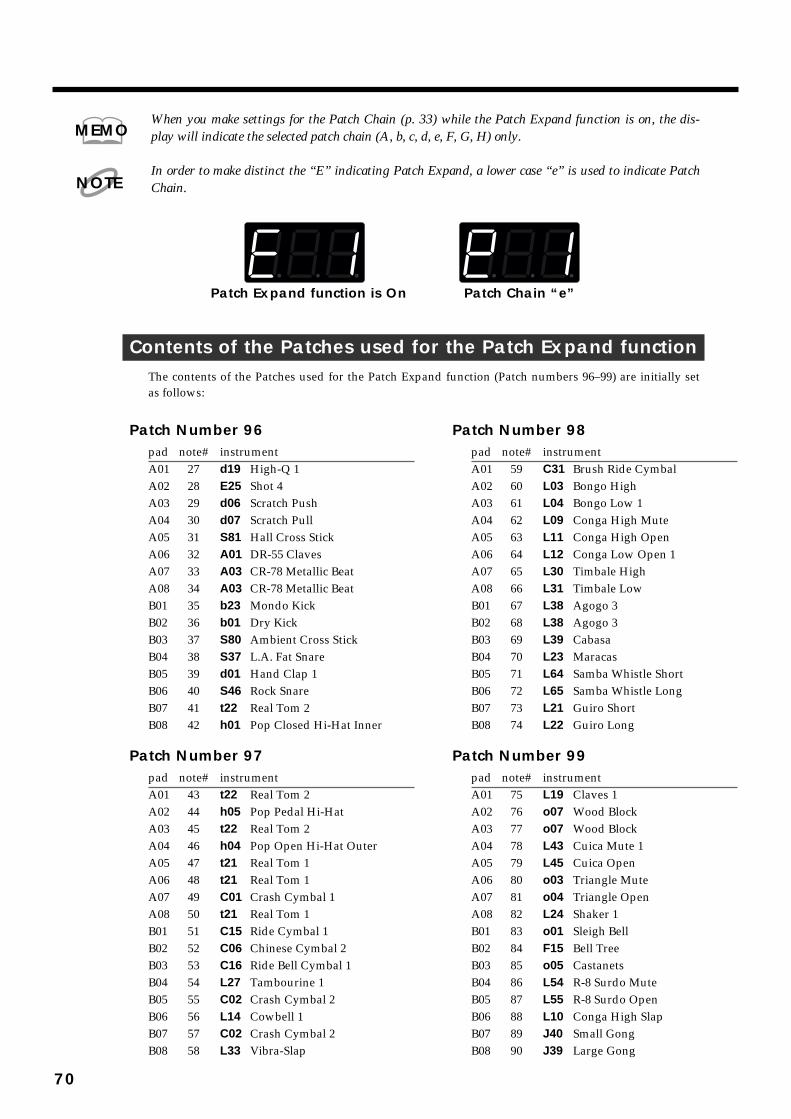
When you make settings for the Patch Chain (p. 33) while the Patch Expand function is on, the dis-play will indicate the selected patch chain (A, b, c, d, e, F, G, H) only.
In order to make distinct the “E” indicating Patch Expand, a lower case “e” is used to indicate PatchChain.
fig.77
Contents of the Patches used for the Patch Expand functionThe contents of the Patches used for the Patch Expand function (Patch numbers 96–99) are initially setas follows:
MEMO
NOTE
Patch Expand function is On Patch Chain “e”
70
Patch Number 96pad note# instrumentA01 27 d19 High-Q 1A02 28 E25 Shot 4A03 29 d06 Scratch PushA04 30 d07 Scratch PullA05 31 S81 Hall Cross StickA06 32 A01 DR-55 ClavesA07 33 A03 CR-78 Metallic BeatA08 34 A03 CR-78 Metallic BeatB01 35 b23 Mondo KickB02 36 b01 Dry KickB03 37 S80 Ambient Cross StickB04 38 S37 L.A. Fat SnareB05 39 d01 Hand Clap 1B06 40 S46 Rock SnareB07 41 t22 Real Tom 2B08 42 h01 Pop Closed Hi-Hat Inner
Patch Number 97pad note# instrumentA01 43 t22 Real Tom 2A02 44 h05 Pop Pedal Hi-HatA03 45 t22 Real Tom 2A04 46 h04 Pop Open Hi-Hat OuterA05 47 t21 Real Tom 1A06 48 t21 Real Tom 1A07 49 C01 Crash Cymbal 1A08 50 t21 Real Tom 1B01 51 C15 Ride Cymbal 1B02 52 C06 Chinese Cymbal 2B03 53 C16 Ride Bell Cymbal 1B04 54 L27 Tambourine 1B05 55 C02 Crash Cymbal 2B06 56 L14 Cowbell 1B07 57 C02 Crash Cymbal 2B08 58 L33 Vibra-Slap
Patch Number 98pad note# instrumentA01 59 C31 Brush Ride CymbalA02 60 L03 Bongo HighA03 61 L04 Bongo Low 1A04 62 L09 Conga High MuteA05 63 L11 Conga High OpenA06 64 L12 Conga Low Open 1A07 65 L30 Timbale HighA08 66 L31 Timbale LowB01 67 L38 Agogo 3B02 68 L38 Agogo 3B03 69 L39 CabasaB04 70 L23 MaracasB05 71 L64 Samba Whistle ShortB06 72 L65 Samba Whistle LongB07 73 L21 Guiro ShortB08 74 L22 Guiro Long
Patch Number 99pad note# instrumentA01 75 L19 Claves 1A02 76 o07 Wood BlockA03 77 o07 Wood BlockA04 78 L43 Cuica Mute 1A05 79 L45 Cuica OpenA06 80 o03 Triangle MuteA07 81 o04 Triangle OpenA08 82 L24 Shaker 1B01 83 o01 Sleigh BellB02 84 F15 Bell TreeB03 85 o05 CastanetsB04 86 L54 R-8 Surdo MuteB05 87 L55 R-8 Surdo OpenB06 88 L10 Conga High SlapB07 89 J40 Small GongB08 90 J39 Large Gong

In the contents of Patch Expand Patches, note numbers 35–81 are compatible with GM PercussionMap which can be used to select Percussion sounds under the General MIDI System, and note num-bers 27–87 are compatible with GS Standard Set which can be used under the GS Format.
The contents of the Patches used by the Patch Expand function (Patches 96–99) can be modified in thesame way as other Patches.
Sounding Priority when Patch Expand is OnIf more than two sounds are set to the same note number and they receive the corresponding note num-ber, only one sound will play, in the priority shown in the following diagram.
fig.78
MEMO
General MIDI System
The General MIDI system is a set of recommendations which seeks to provide a way to go beyond the limitations of proprietary designs, and standardize the MIDI capabilities of sound generating devices. Sound generating devices and music files that meets the General MIDI standard bears the General MIDI logo ( ). Music files bearing the General MIDI logo can be played back using any General MIDI sound generating unit to produce essentially the same musical performance. General MIDI supports the GM Percussion Map in channel 10.
GS Format
The GS Format ( ) is Roland's set of specifications for standardizing the performance of sound generating devices. In addition to including support for everything defined by the General MIDI System, the highly-compatible GS Format additionally offers an expanded number of sounds, provides for the editing of sounds, and spells out many details for a wide range of extra features, including effects such as reverb and chorus. Designed with the future in mind, the GS Format can readily include new sounds and support new hardware features when they arrive. Since it is upwardly compatible with the General MIDI System, Roland's GS Format is capable of reliably playing back GM Scores equally as well as it performs GS Music Files (music files that has been created with the GS Format in mind). The GS Standard set is one of the percussion sets which can be used in GS drum part. (Default; ch 10.)
MEMO
highpriority
lowpriority
The currentlyselected Patch 96 97 98 99
71
1
2
3
4
5
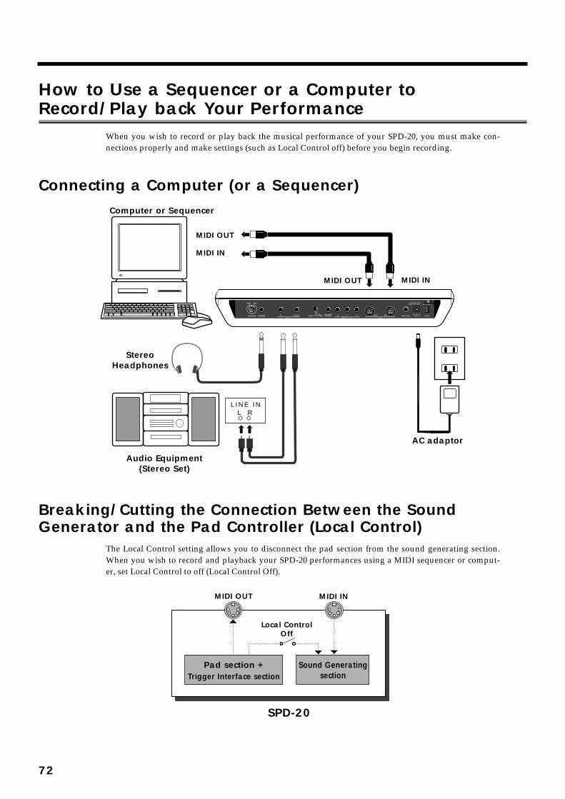
How to Use a Sequencer or a Computer toRecord/Play back Your Performance
When you wish to record or play back the musical performance of your SPD-20, you must make con-nections properly and make settings (such as Local Control off) before you begin recording.
Connecting a Computer (or a Sequencer)fig.79
Breaking/Cutting the Connection Between the SoundGenerator and the Pad Controller (Local Control)
The Local Control setting allows you to disconnect the pad section from the sound generating section.When you wish to record and playback your SPD-20 performances using a MIDI sequencer or comput-er, set Local Control to off (Local Control Off).
fig.80
L I N E I NL R
AC adaptor
Audio Equipment(Stereo Set)
StereoHeadphones
Computer or Sequencer
MIDI OUT
MIDI IN
MIDI OUT MIDI IN
Pad section + Sound Generatingsection
Local ControlOff
MIDI OUT MIDI IN
SPD-20
Trigger Interface section
72

1 Turn off the power switch.
2 While pressing [PATCH CHAIN], turn the power switch back on.
The following message will scroll across the display, and Local Control will be turned off.fig.81
When Local Control is set to “Off,” the internal sound generator does not sound, evenwhen the Pad is struck, and in PLAY mode, the MIDI Indicator lights.
Local Control Off is lifted and Local Control On restored the next time the power is turned on.
Regardless of the Local Control setting, messages received at MIDI IN will play the internal soundgenerator, and the pads and pedals will transmit messages from MIDI OUT.
fig.82
If you have connected the SPD-20 to a MIDI sequencer (or a personal computer running MIDIsequencing software) that has a “soft(ware) thru” function, set the SPD-20 to Local Off.
It is also useful to set Local Off when using the SPD-20 as a pad controller to play only external soundmodules.
NOTE
MEMO
MIDI Sequencer
Soft ThruOn
InternalMemory
Pad section + Sound Generatingsection
Local ControlOff
MIDI OUT MIDI IN MIDI OUT MIDI IN
SPD-20
Trigger Interface section
MEMO
Soft Thru
“Soft thru” is a function (provided in most MIDI sequencers) by which the messages received atMIDI IN of the sequencer are re-transmitted from MIDI OUT. (For details, refer to the manual ofyour sequencer or sequencer software.)
When the sequencer’s soft thru is turned on, messages it receives at its MIDI IN will be re-trans-mitted from its MIDI OUT. If the connected SPD-20 is set to Local On, it would sound each notetwice: once in response to the message from the pad section, and once again in response to theMIDI message sent via the software thru function of the sequencer.
MEMO
73
1
2
3
4
5

How to Set Up the SPD-20 for SequencingIf you wish to record and playback an SPD-20 performance on a MIDI sequencer orcomputer, make the following settings. (these are the factory settings.)
• For each pad you wish to use, set TX CH (p. 61) to the same channel as the Basic Channel.
• For each pad you wish to use, set Note # (p. 62) for the pads so that they don’t overlap.
• For each pad you wish to use, set CURVE (p. 64) to “Lnr”.
• For each pad you wish to use, set SENS (p. 64) to 8.
If you wish to record and playback Patch changes made during a performance, you willneed to make the following settings as well.
• For only one pad, set a Program Number that matches the Patch number (p. 65).
If you wish to record and playback the pedal controller hi-hat sound (H01–H17) layeredwith another instrument, following setting will be necessary.
• Assign a hi-hat cymbal for pedal control instrument (H01–H17) to pad bank A.
If you assign these instruments to pad bank B, recording will be correct, but since the SPD-20 ignoresincoming note messages for pad bank B, the Pedal hi-hat will not be heard during playback.
74

Storing the SPD-20’s Data in External Devices (Bulk Dump)The Patch data in the SPD-20 can be transmitted either singly or collectively to another SPD-20 (or to asequencer). SPD-20 data is transmitted and received according to the Device ID number which has beenset for each unit. (In the SPD-20, the Basic Channel number is also used as the Device ID number. p. 78)The operation of transmitting this data is called a “Bulk Dump”; receiving this data is called a “BulkLoad.”
How to Transmit (Bulk Dump)The SPD-20 transmits stored data.
fig.83
Connect the MIDI OUT of the SPD-20 to the MIDI IN of the sequencer.
1 Set the ID (the same as the Basic Channel’s; p. 67) of the devicetransmitting the Exclusive Messages.
2 Press [EDIT] to enter the Edit mode.
3 Use [ ] or [ ] to select the BULK DUMP in the SYSTEM parametergroup.
4 Use PATCH/VALUE [-] or [+] to select the Patch data you wish totransmit (ALL/1–99).
If ALL is selected, all Patch data, Patch Chain data, and system parameter data will betransmitted at once. If you wish to save an individual patch, select the patch number youwish to send with the value buttons.
5 Set the receiving MIDI device so that it will be able to receiveExclusive messages.
6 Press [ALL/ENTER] and data transmission will begin.
fig.84
If you wish to stop the operation during transmission, press [EDIT].
SPD-20
MIDI OUTMIDI IN
Computer or Sequencer
75
1
2
3
4
5

6 If you wish to transmit other Patch data, repeat steps 3–5.
7 Press [EDIT] to return to the Play mode.
How to Receive (Bulk Load)Here’s how to receive Patch data that was stored in another SPD-20 (or in a sequencer).
fig.85
Connect the MIDI OUT of the transmitting device to the MIDI IN of the SPD-20.
When data is received, the previously existing patch settings will be lost.
1 Make sure that the MIDI channel of the transmitting device matchesthe Basic Channel of the receiving SPD-20 (p. 67).
If you transfer Exclusive data from another SPD-20, set the basic channels on both unitsmatch. If you receive the Exclusive data that was stored in a sequencer, set the basic chan-nel to match the same number which was set when you saved data in the sequencer.
2 Transmit the Exclusive data from the other MIDI device. Whenreception begins, “Lod” appears in the SPD-20’s display.You are returned to the previous display as soon as the Bulk Load has been completed.
When Patch data is received, the bulk dumped Patch data is written to identical Patch numbers.
For example, if you save Patch Number 21 using bulk dump, then when the Patch data is bulk loaded,it is stored in Patch Number 21.
Exclusive Messages cannot be received while Patch Copy and Patch Chain are being received.
Exclusive data transmission and reception requires a great deal of processing, so it is best to avoidplaying or editing while transmission is going on. Also, Exclusive data transmission can require a sig-nificant amount of time, so allow a reasonable time for these operations. Data cannot be transmittedwhile incoming Bulk data is being processed, nor can data be received while Bulk data is being trans-mitted.
SPD-20
MIDI OUTMIDI IN
Computer or Sequencer
NOTE
MEMO
NOTE
76
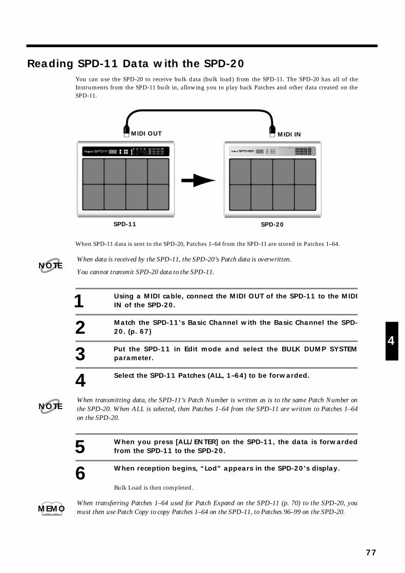
Reading SPD-11 Data with the SPD-20You can use the SPD-20 to receive bulk data (bulk load) from the SPD-11. The SPD-20 has all of theInstruments from the SPD-11 built in, allowing you to play back Patches and other data created on theSPD-11.
fig. 86-a
When SPD-11 data is sent to the SPD-20, Patches 1–64 from the SPD-11 are stored in Patches 1–64.
When data is received by the SPD-11, the SPD-20’s Patch data is overwritten.
You cannot transmit SPD-20 data to the SPD-11.
1 Using a MIDI cable, connect the MIDI OUT of the SPD-11 to the MIDIIN of the SPD-20.
2 Match the SPD-11’s Basic Channel with the Basic Channel the SPD-20. (p. 67)
3 Put the SPD-11 in Edit mode and select the BULK DUMP SYSTEMparameter.
4 Select the SPD-11 Patches (ALL, 1–64) to be forwarded.
When transmitting data, the SPD-11’s Patch Number is written as is to the same Patch Number onthe SPD-20. When ALL is selected, then Patches 1–64 from the SPD-11 are written to Patches 1–64on the SPD-20.
5 When you press [ALL/ENTER] on the SPD-11, the data is forwardedfrom the SPD-11 to the SPD-20.
6 When reception begins, “Lod” appears in the SPD-20’s display.
Bulk Load is then completed.
When transferring Patches 1–64 used for Patch Expand on the SPD-11 (p. 70) to the SPD-20, youmust then use Patch Copy to copy Patches 1–64 on the SPD-11, to Patches 96–99 on the SPD-20.
SPD-11
MIDI OUT MIDI IN
SPD-20
NOTE
NOTE
MEMO
77
1
2
3
4
5
What is Device IDAccording to the explanation on page 58 of this manual, Exclusive data is not differentiated by channel.However, this would mean that in a complex MIDI system that contained two or more SPD-20s, itwould not be possible to transmit Exclusive data to only a specific SPD-20. To get around this problem,each SPD-20 has its own Device ID number (1–16) on which it transmits and receives Exclusive data.Exclusive data can be received only when the Device ID number of the receiving device matches theDevice ID number of the transmitting device.
In the SPD-20, the Basic Channel number is also used as the Device ID number.
In some devices, the MIDI channel number and the Device ID number can be set independently, andwill not necessarily be the same. When transferring Bulk data to another device, refer to the operationmanual for that device.
If you are using a sequencer to control two or more SPD-20s, you can set each unit to a differentDevice ID so that select data can be sent to each unit. But remember that the Basic Channel numberswill also be different.
NOTE
MEMO
78

Here you will find materials that are useful in helping you get the most out of your SPD-20. Read thesections as needed.
Taking Advantage of the On-board Effects
Effect listFX The parameterTYPE Name Explanation affected by “Time”
1. Room (Bright) A bright-sounding room reverb Reverb Time
2. Room (Standard) A standard room reverb Reverb Time
3. Room (Dark) A dark-sounding room reverb Reverb Time
4. Hall (Bright) A bright-sounding hall reverb Reverb Time
5. Hall (Standard) A standard hall reverb Reverb Time
6. Hall (Dark) A dark-sounding hall reverb Reverb Time
7. Plate (Bright) A bright-sounding plate reverb Reverb Time
8. Standard Plate A standard plate reverb Reverb Time
9. Chorus + Reverb Chorus and reverb Reverb Time
10. Tremolo Reverb Tremolo and reverb Reverb Time
11. Chorus A standard chorus Chorus Rate
12. Chorus + Room Chorus and room reverb Reverb Time
13. Chorus + Hall Chorus and hall reverb Reverb Time
14. Chorus + Plate Chorus and plate reverb Reverb Time
15. Flanger A standard flanger Flanger Rate
16. Flanger + Reverb Flanger and reverb Reverb Time
17. Flanger + Reverb Flanger and reverb Flanger Rate
18. Pitched Delay + Reverb Pitch-shifted delay and reverb Delay Pitch
19. Pitched Delay + Reverb Pitch-shifted delay and reverb Delay Rate
20. Stereo Delay Stereo delay (without feedback) Delay Time
21. Stereo Delay Stereo delay (with feedback) Delay Time
22. Panning Delay Panned delay (without feedback) Delay Time
23. Panning Delay Panned delay (with feedback) Delay Time
24. Chorus + Delay Chorus + stereo delay (without feedback) Delay Time
25. Chorus + Delay Chorus + stereo delay (with feedback) Delay Time
CHAPTER 5 Supplementary Materials
79
1
2
3
4
5
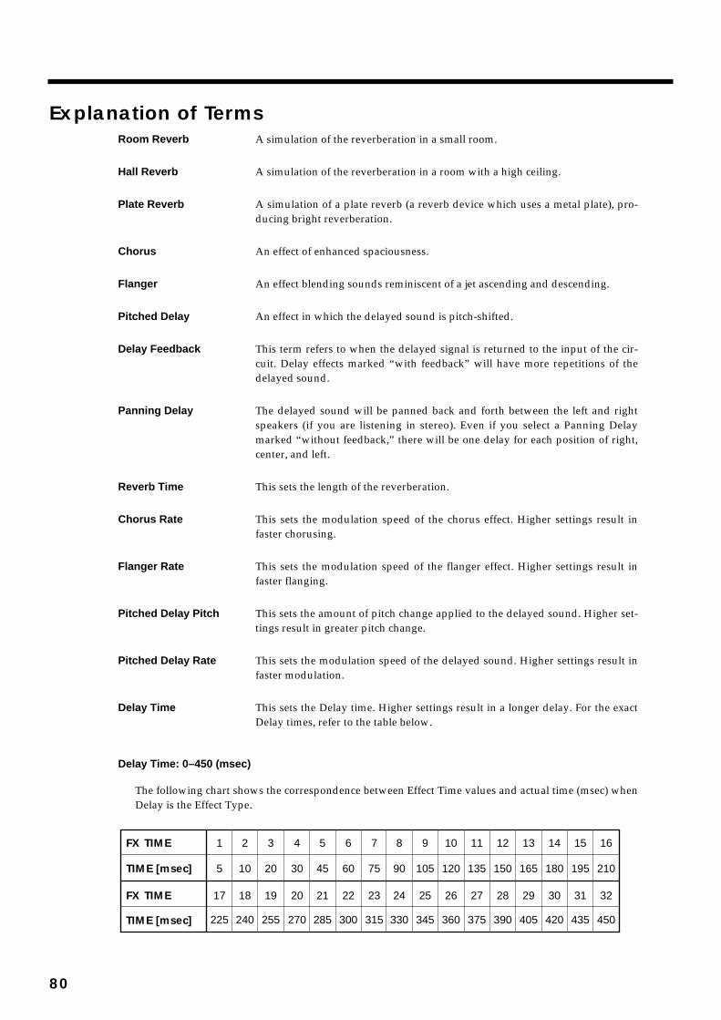
Explanation of TermsRoom Reverb A simulation of the reverberation in a small room.
Hall Reverb A simulation of the reverberation in a room with a high ceiling.
Plate Reverb A simulation of a plate reverb (a reverb device which uses a metal plate), pro-ducing bright reverberation.
Chorus An effect of enhanced spaciousness.
Flanger An effect blending sounds reminiscent of a jet ascending and descending.
Pitched Delay An effect in which the delayed sound is pitch-shifted.
Delay Feedback This term refers to when the delayed signal is returned to the input of the cir-cuit. Delay effects marked “with feedback” will have more repetitions of thedelayed sound.
Panning Delay The delayed sound will be panned back and forth between the left and rightspeakers (if you are listening in stereo). Even if you select a Panning Delaymarked “without feedback,” there will be one delay for each position of right,center, and left.
Reverb Time This sets the length of the reverberation.
Chorus Rate This sets the modulation speed of the chorus effect. Higher settings result infaster chorusing.
Flanger Rate This sets the modulation speed of the flanger effect. Higher settings result infaster flanging.
Pitched Delay Pitch This sets the amount of pitch change applied to the delayed sound. Higher set-tings result in greater pitch change.
Pitched Delay Rate This sets the modulation speed of the delayed sound. Higher settings result infaster modulation.
Delay Time This sets the Delay time. Higher settings result in a longer delay. For the exactDelay times, refer to the table below.
Delay Time: 0–450 (msec)
The following chart shows the correspondence between Effect Time values and actual time (msec) whenDelay is the Effect Type.
fig.94
1 2 3 4 5 6 7 8 9 10 11 12 13 14 15 16
17
FX TIME
5 10 20 30 45 60 75 90 105 120 135 150 165 180 195 210TIME [msec]
225 240 255 270 285 300 315 330 345 360 375 390 405 420 435 450
18 19 20 21 22 23 24 25 26 27 28 29 30 31 32FX TIME
TIME [msec]
80

Hints on Using ReverbReverb gives presence and spaciousness to any sound, whether solo or background. However, exces-sively high effects levels and long effects times may make the performance difficult to follow (becausesounds are blurred), or make the rhythm less precise. There is a definite relationship between effecttime and effect level. Here are two hints on using Reverb, based on that relationship.
• If you want to use a long effect time, decrease the effect level to reduce muddiness.
• If you want to use a high effect level, shorten the effect time to reduce muddiness.
Hints on Using DelayWhile Reverb creates a lingering resonance, Delay creates quite a different effect. For Delay effects, theeffect time setting can create significant differences in the resulting sound. For example, when playing amelodic solo using a mallet-type Instrument, an extremely short Delay time can be used to thicken thesound. On the other hand, a longer repeating Delay can be set to a Delay time of a half-note or quarter-note that matches the tempo of the song.
If you are listening to the SPD-20 in stereo, it can also be interesting to select effect type 22 or 23 (PannedDelay) and select a Pan setting of “random.”
Hints on Using Chorus/FlangerFor Chorus/Flanger effects, the Time parameter determines the rate (the speed of modulation).
For Chorus, lower settings of the time parameter will result in a more spacious sound, and higher set-tings will result in a more tremolo-like effect. Flanging is often used on metallic sounds such as cymbalsor Hi-Hats to produce a frequently-heard effect.
Hints on Making Parameter SettingsEffects provide many possibilities, but if you always use the same heavily-applied Reverb or Chorus, allthe Patches will sound the same. It is important to choose effect settings that are appropriate for thesong or suited to the role of the Instrument (solo, backing, special effects, etc.).
The FX SEND in the SOUND parameter group allows you to set the effect depth independently for theInstrument assigned to each pad, so it is possible, for instance, to apply flanging only to the cymbals. Inthe case of Reverb, higher settings of FX SEND will create the impression of the Instrument beingplayed further away, so you might set the FX SEND parameter to a different value for each Instrumentto create spatial contrast. By utilizing the Pan setting (the stereo position) and the Chorus effect, you cancontrol a vast performance space.
Hints on Not Using EffectsSpeaking of contrast, it can also be very “effective” to not use effects. Some possibilities are as follows.
• To apply effects to certain Instruments and not to others.
• To switch to a non-effect Patch at a strategic moment.
As an example of the first possibility, you might try using an ethnic percussion Instrument—such as asurdo—without any effects for a feeling of authenticity. As an example of the second possibility, youcould switch from a Patch with deep Reverb to a Patch with no effects (or vice versa) to reinforce musi-cal movement or development within a song.
81
1
2
3
4
5

Troubleshooting
When playing the internal sound generator
• No soundIs the volume set to 0?
➜ Check the SPD-20 volume, and the volume of the amp system and mixer.
Can you here sound through the headphones?
➜ If there is sound through the headphones, the problem may be that a connecting cable is dam-aged, or there is a problem with the amp or mixer. Check the amplification system and the audioconnections.
Is Layer Off selected?
➜ When Layer Off is selected, the sound from only one side is played.
Could LEVEL in the SOUND parameter group be set to 0?
➜ Set the levels to an appropriate value (p. 23).
Is INST (Instrument Assign) in the SOUND parameter group set to “oFF”?
➜ A pad will not sound if its Instrument Assign parameter is set to “oFF” (p. 22).
Is Local Control turned off?
➜ If Local Control is turned off, the pad section is disconnected from the sound generator, so play-ing the Pads will not produce sound (p. 72).
Is CURVE (Velocity Curve) in the SOUND parameter group inappropriate?
➜ Make appropriate settings for the Velocity Curve parameter (p. 24).
• No power/Power on, but unit does not operateAre you using the supplied AC adaptor?
➜ Other AC adaptors may not work properly. If the SPD-20 does not operate even with the correctAC adaptor, check whether the correct AC line voltage is being supplied.
It is best to avoid connecting many devices of high power consumption to the same AC outlet, or usingan excessive number of AC outlet expansion plugs.
• The volume is too lowIs the volume turned down?
➜ Check the SPD-20 volume, and the volume of the amp system and/or mixer.
Are LEVEL in the SOUND parameter group set too low?
➜ Set the LEVEL to appropriate levels (p. 23).
Is CURVE (Velocity Curve) in the SOUND parameter group inappropriate?
➜ Make appropriate settings for the Velocity Curve parameter(p. 24).
Is SENS (Velocity Sens) in the MIDI parameter group set too low?
➜ Make appropriate settings for the Velocity Sensitivity parameter.
• The sound is wrongAre the SOUND parameters set correctly?
➜ Modify the SOUND parameters (p. 22).
NOTE
82

• You hear sounds that you did not selectIs the layer function on?
➜ Set Layer to Off (p. 15).
Is an external MIDI sound module being played from that pad?
➜ If you do not wish to trigger an external MIDI sound module, set the Transmit Channel in theMIDI parameter to “oFF” (p. 61).
• Soft strikes does not produce soundIs the TRIG THRESHOLD setting too high?
➜ Set TRIG THRESHOLD to an appropriate value (p. 44).
Is CURVE (Velocity Curve) in the SOUND parameter group inappropriate?
➜ Make appropriate settings for the Velocity Curve parameter (p. 24).
• When two pads are struck simultaneously, only one of the sounds is playedAre you striking the center of the pad?
➜ When striking two pads simultaneously, you should hit them both in the center. Furthermore,you can be more sure of sounding both pads if you strike them with the timing slightly off.
With the SPD-20, the prevention of crosstalk (incorrect actions caused by the vibration from anotherpad) is processed internally. Thus, if when two pads are struck at the same time the signal output byone of the pads is extremely weak, then that sound is prevented from sounding. Being sure to strikeboth pads in their centers, with the same force/strength makes it difficult for the sound difficult to beomitted.
When external pads are connected
When using external pads, set the TRIG TYPE (p. 45).
The volume can’t be controlled by adjusting the striking strength➜ Make the TRIG TYPE match (p. 45).
➜ Make the TRIG SENS and TRIG CURVE match (p. 43, p. 47).
When striking repeatedly, some sounds are lost➜ Make the TRIG TYPE match (p. 45).
In some cases, when using pads or acoustic drum triggers from other manufacturers, you should makeyour settings in Advanced Trigger Parameters (p. 48).
There is no sound when rim shots are played➜ Play the rim shot correctly (p. 39).
Are stereo cables used to connect the pads?
➜ Connect using stereo cables.
➜ On the PD-120, rim shots can be played when you use Trigger Inputs 1 and 2.
MEMO
MEMO
MEMO
83
1
2
3
4
5
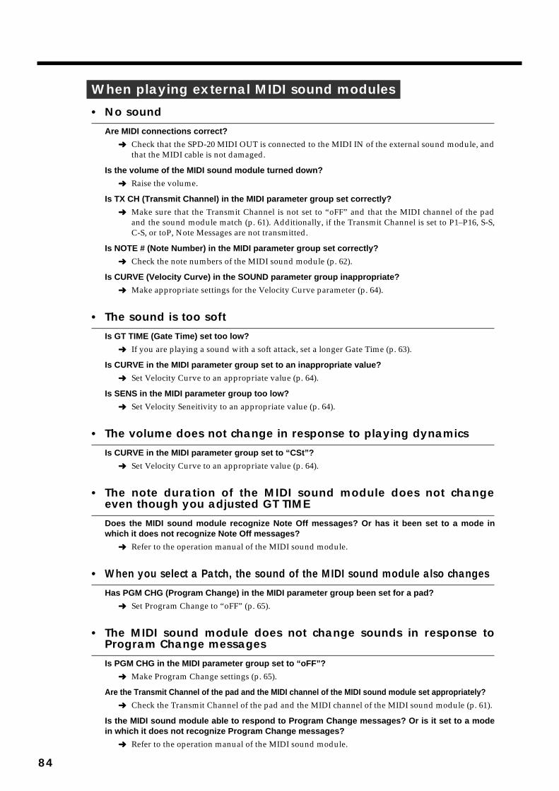
When playing external MIDI sound modules
• No soundAre MIDI connections correct?
➜ Check that the SPD-20 MIDI OUT is connected to the MIDI IN of the external sound module, andthat the MIDI cable is not damaged.
Is the volume of the MIDI sound module turned down?
➜ Raise the volume.
Is TX CH (Transmit Channel) in the MIDI parameter group set correctly?
➜ Make sure that the Transmit Channel is not set to “oFF” and that the MIDI channel of the padand the sound module match (p. 61). Additionally, if the Transmit Channel is set to P1–P16, S-S,C-S, or toP, Note Messages are not transmitted.
Is NOTE # (Note Number) in the MIDI parameter group set correctly?
➜ Check the note numbers of the MIDI sound module (p. 62).
Is CURVE (Velocity Curve) in the SOUND parameter group inappropriate?
➜ Make appropriate settings for the Velocity Curve parameter (p. 64).
• The sound is too softIs GT TIME (Gate Time) set too low?
➜ If you are playing a sound with a soft attack, set a longer Gate Time (p. 63).
Is CURVE in the MIDI parameter group set to an inappropriate value?
➜ Set Velocity Curve to an appropriate value (p. 64).
Is SENS in the MIDI parameter group too low?
➜ Set Velocity Seneitivity to an appropriate value (p. 64).
• The volume does not change in response to playing dynamicsIs CURVE in the MIDI parameter group set to “CSt”?
➜ Set Velocity Curve to an appropriate value (p. 64).
• The note duration of the MIDI sound module does not changeeven though you adjusted GT TIMEDoes the MIDI sound module recognize Note Off messages? Or has it been set to a mode inwhich it does not recognize Note Off messages?
➜ Refer to the operation manual of the MIDI sound module.
• When you select a Patch, the sound of the MIDI sound module also changesHas PGM CHG (Program Change) in the MIDI parameter group been set for a pad?
➜ Set Program Change to “oFF” (p. 65).
• The MIDI sound module does not change sounds in response toProgram Change messagesIs PGM CHG in the MIDI parameter group set to “oFF”?
➜ Make Program Change settings (p. 65).
Are the Transmit Channel of the pad and the MIDI channel of the MIDI sound module set appropriately?
➜ Check the Transmit Channel of the pad and the MIDI channel of the MIDI sound module (p. 61).
Is the MIDI sound module able to respond to Program Change messages? Or is it set to a modein which it does not recognize Program Change messages?
➜ Refer to the operation manual of the MIDI sound module.
84
• Two sounds are playedIs the Layer function set to On?
➜ Turn the Layer function off (p. 15).
• When the pad is struck, the sound is intermittentIs the Gate Time set to ALt?
➜ Set the Gate Time to something other than ALt (p. 63).
When playing the internal sound generator of the SPD-20
• No soundDoes the Basic Channel of the SPD-20 match the Transmit Channel of the external MIDI device?
➜ Set both devices to the same channel (p. 67).
Set the Basic Channel (BASIC CH; p. 67) as the SPD-20’s Receive Channel.
Is the layer function on?
➜ When the layer function is on, note messages assigned to pad bank B will be ignored. Turn thelayer function off.
Is the Instrument you wish to play assigned to a pad?
➜ Assign the Instrument to a pad (p. 22).
Is the Note Number set correctly?
➜ The SPD-20 will not produce sound if it receives a Note Number which has not been assigned to a pad.Modify the Note Number, or select a Patch which has different note numbers assigned to it (p. 62).
Have you assigned the same Note Number to more than one pad?
➜ Even if you assign the same Note Number to more than one pad, only one Instrument willsound. Set different note numbers for each pad (p. 62).
• Note Numbers not set to a Patch are playedIs Patch Expand on?
➜ Set Patch Expand to Off (p. 69).
When a footswitch is connected
• The footswitch does not workIs the footswitch connected correctly?
➜ Connect the footswitch properly (p. 15).
• The MIDI sound module does not sustain notes when you pressthe FootswitchIs the Hold Pedal function set?
➜ Turn on the Hold Pedal function (p. 41).
Is the MIDI sound module able to respond to Hold messages?
➜ Refer to the operation manual of the MIDI sound module.
MEMO
85
1
2
3
4
5
• The internal sound generator does not hold notes when pressedHave you chosen an instrument that can hold tones?
➜ Holding with the internal sound generator is limited to certain specific Instruments (p . 88).
Others
• The Patch you set in a Patch Chain is not selectedIs the Patch Chain set correctly?
➜ Check whether the Patch Chain is set correctly (p. 33).
If you do not press [ENTER] after entering all of the Patch Numbers, the Patch Chain setting will notbe completed.
Is the SPD-20 in the Play mode?
➜ The Patch Chain function works only in the Play mode.
Is the SPD-20 in the Patch Chain Play mode?
➜ While in Patch Chain Play mode, letters of the alphabet (A, b, C, d, e, F, G, H) appear to the leftof the Patch Numbers.
• Exclusive messages are not receivedDoes the Device ID number of the transmitting MIDI device match the Basic Channel (Device IDnumber) of the SPD-20?
➜ Set the basic channel (p. 67).
Set the SPD-20’s Device ID to the Basic Channel.
• The effect does not workIs [FX ON/OFF] turned off?
➜ Press [FX ON/OFF] to on (p. 9).
Is the FX LEVEL at 0?
➜ Set the FX LEVEL to an appropriate level (p. 28).
Is the FX SEND at 0?
➜ Set the FX SEND LEVEL to an appropriate level (p. 25).
• The display flashes rapidly during setting of the Note Numbers➜ This indicates that during setting of Note Numbers the same Patch is being set to different pads
(including pad bank A/B). If you set the same Note Numbers to different pads, the NoteNumber of the pad determined to have higher priority (p. 67) will take precedence.
When Patch Expand is in effect, check to see if the same Note Number is used in any more than one ofthe five patches.
• The sound recorded to a sequencer is not the same as that played backAre the pad’s Note Numbers overlapping with those of another pad?
➜ Make all Note Numbers on the pads you are using different. The Note Number flashes rapidlywhen Note Numbers from different pads overlap (p. 62).
NOTE
MEMO
MEMO
86
Error MessagesIf a problem occurs during operation, an error message will be displayed. Take the appropriate actionas described in this section.
fig.87
A MIDI cable is not connected properly or may be damaged.
➜ Check the MIDI cable(s) and the connections with the other device(s).fig.88
Data loading was not successful.
➜ Try loading once again. Pressing any button will return to the previous display.fig.89
MIDI data was received incorrectly.
Press any button on the front panel and the previous display will appear.
➜ If this message appears repeatedly, consult your dealer or the nearest Roland ServiceCenter.
fig.90
Too much MIDI data was received from another MIDI device.
➜ Reduce the amount of MIDI data transmitted by the other device. Or, re-transmit the dataafter a pause to reduce the amount of MIDI data transmitted all at once. Pressing any but-ton will return you to the previous display.
fig.91
The internal memory data has been lost.
➜ Press any button on the front panel. All data will be initialized, and the previous display willreappear.
If this happens, all the data in the SPD-20 will be reset to the factory presets.
fig.92
This message indicates that there is an irregularity in the voltage of the pad detection circuit. Press anybutton on the front panel and the previous display will reappear.
➜ If the previous display does not reappear, no matter which button you press, contact thenearest Roland Service Center. Sometimes this error message will appear if you strike apad while turning on the power. In this event, turn the power off and then on again.
fig.93
The memory-backup battery is exhausted.
➜ If the backup battery runs down completely, the data in internal memory will be lost.Contact your dealer or the nearest Roland Service Center as soon as possible to have thebattery replaced.
Press any button on the panel to return to the previous display.
NOTE
87
1
2
3
4
5
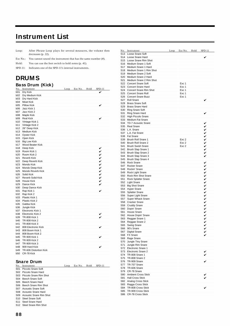
Instrument List
88
Loop: After Phrase Loop plays for several measures, the volume thendecreases (p. 22).
Exc No.: You cannot sound the instrument that has the same number (#).
Hold: You can use the foot switch to hold notes (p. 41).
SPD-11: Indicates one of the SPD-11's internal instruments.
DRUMSBass Drum (Kick)No. Instrument Loop Exc No. Hold SPD-11b01 Dry Kick ✔
b02 Dry Medium Kickb03 Dry Hard Kickb04 Meat Kickb05 Pillow Kick ✔
b06 Jazz Kick 1b07 Jazz Kick 2b08 Maple Kickb09 Real Kick ✔
b10 Vintage Kick 1b11 Vintage Kick 2b12 26" Deep Kickb13 Medium Kickb14 Oyster Kickb15 Open Kickb16 Big Low Kickb17 Wood Beater Kickb18 Deep Kick ✔
b19 Room Kick 1 ✔
b20 Room Kick 2 ✔
b21 Reverb Kick ✔
b22 Deep Reverb Kick ✔
b23 Mondo Kick ✔
b24 Mondo Deep Kick ✔
b25 Mondo Reverb Kick ✔
b26 Solid Kick ✔
b27 Reverb Solid Kick ✔
b28 House Kick ✔
b29 Dance Kick ✔
b30 Deep Dance Kickb31 Rap Kick 1 ✔
b32 Rap Kick 2b33 Plastic Kick 1b34 Plastic Kick 2b35 Gabba Kickb36 Jungle Kickb37 Electronic Kick 1b38 Electronic Kick 2 ✔
b39 TR-808 Kick 1 ✔
b40 TR-808 Kick 2b41 TR-808 Kick 3b42 808 Electronic Kick ✔
b43 808 Boom Kick 1b44 808 Boom Kick 2b45 TR-909 Kick 1 ✔
b46 TR-909 Kick 2b47 TR-909 Kick 3b48 909 Hard Kick ✔
b49 TR-606 Distortion Kickb50 CR-78 Kick
Snare DrumNo. Instrument Loop Exc No. Hold SPD-11S01 Piccolo Snare SoftS02 Piccolo Snare HardS03 Piccolo Snare Rim ShotS04 Beech Snare SoftS05 Beech Snare HardS06 Beech Snare Rim ShotS07 Acoustic Snare SoftS08 Acoustic Snare HardS09 Acoustic Snare Rim ShotS10 Steel Snare SoftS11 Steel Snare HardS12 Steel Snare Rim Shot
No. Instrument Loop Exc No. Hold SPD-11S13 Loose Snare SoftS14 Loose Snare Hard ✔
S15 Loose Snare Rim ShotS16 Medium Snare 1 SoftS17 Medium Snare 1 HardS18 Medium Snare 1 Rim ShotS19 Medium Snare 2 SoftS20 Medium Snare 2 HardS21 Medium Snare 2 Rim ShotS22 Concert Snare Soft Exc 1S23 Concert Snare Hard Exc 1S24 Concert Snare Rim Shot Exc 1S25 Concert Snare Roll Exc 1S26 Concert Snare Buzz Exc 1S27 Roll Snare ✔
S28 Brass Snare SoftS29 Brass Snare HardS30 Ring Snare SoftS31 Ring Snare Hard ✔
S32 High Piccolo SnareS33 Medium Fat SnareS34 TD-7 Acoustic Snare ✔
S35 Real Snare ✔
S36 L.A. Snare ✔
S37 L.A. Fat Snare ✔
S38 Fat Snare ✔
S39 Brush Roll Snare 1 Exc 2 ✔
S40 Brush Roll Snare 2 Exc 2 ✔
S41 Brush Swish Snare Exc 2 ✔
S42 Brush Slap Snare 1 ✔
S43 Brush Slap Snare 2 ✔
S44 Brush Slap Snare 3 ✔
S45 Brush Slap Snare 4S46 Rock Snare ✔
S47 Rocker Snare ✔
S48 Rockin' Snare ✔
S49 Rock Light Snare ✔
S50 Rock Rim Shot Snare ✔
S51 Rock Splatter Snare ✔
S52 Light Snare ✔
S53 Big Shot Snare ✔
S54 Hyper Snare ✔
S55 Splatter Snare ✔
S56 Super Light Snare ✔
S57 Super Whack Snare ✔
S58 Cracker Snare ✔
S59 Cruddy Snare ✔
S60 Dopin' Snare ✔
S61 House Snare ✔
S62 House Dopin' Snare ✔
S63 Reggae Snare 1 ✔
S64 Reggae Snare 2 ✔
S65 Swing Snare ✔
S66 90's Snare ✔
S67 Digital Snare ✔
S68 FX Snare ✔
S69 Rage SnareS70 Jungle Tiny SnareS71 Jungle Rim SnareS72 Electronic Snare 1S73 Electronic Snare 2 ✔
S74 TR-808 Snare 1 ✔
S75 TR-808 Snare 2S76 TR-909 Snare ✔
S77 TR-707 SnareS78 TR-606 SnareS79 CR-78 SnareS80 Ambient Cross Stick ✔
S81 Hall Cross Stick ✔
S82 Analog Cross StickS83 Ragga Cross StickS84 TR-808 Cross Stick ✔
S85 TR-909 Cross StickS86 CR-78 Cross Stick

Tom-TomNo. Instrument Loop Exc No. Hold SPD-11t01 Big Tom 1 Softt02 Big Tom 1 Hardt03 Big Tom 2 Softt04 Big Tom 2 Hardt05 Studio Tom 1 Softt06 Studio Tom 1 Hardt07 Studio Tom 2 Softt08 Studio Tom 2 Hardt09 Jazz Tom 1 Softt10 Jazz Tom 1 Hardt11 Jazz Tom 2 Softt12 Jazz Tom 2 Hardt13 Vintage Tom 1 Softt14 Vintage Tom 1 Hardt15 Vintage Tom 2 Softt16 Vintage Tom 2 Hardt17 Double Head Tom 1 ✔
t18 Double Head Tom 2 ✔
t19 Fusion Tom 1t20 Fusion Tom 2t21 Real Tom 1 ✔
t22 Real Tom 2 ✔
t23 Birch Tom 1t24 Birch Tom 2t25 Bowl Tom 1t26 Bowl Tom 2t27 Room Tom 1t28 Room Tom 2t29 Acoustic Tom 1 ✔
t30 Acoustic Tom 2 ✔
t31 Rock Tom 1 ✔
t32 Rock Tom 2 ✔
t33 Brush Slap Tom 1 ✔
t34 Brush Slap Tom 2 ✔
t35 Electronic Tomt36 2-Tone Electronic Tomt37 Bright Electronic Tomt38 TR-808 Tom ✔
t39 TR-909 Tomt40 909 Whack Tom
Hi-Hat CymbalNo. Instrument Loop Exc No. Hold SPD-11h01 Pop Closed Hi-Hat Inner Exc 31 ✔
h02 Pop Closed Hi-Hat Outer Exc 31 ✔
h03 Pop Open Hi-Hat Inner Exc 31 ✔
h04 Pop Open Hi-Hat Outer Exc 31 ✔
h05 Pop Pedal Hi-Hat Exc 31 ✔
h06 Real Closed Hi-Hat Inner Exc 31 ✔
h07 Real Closed Hi-Hat Outer Exc 31 ✔
h08 Real Open Hi-Hat Inner Exc 31 ✔
h09 Real Open Hi-Hat Outer Exc 31 ✔
h10 Real Pedal Hi-Hat Exc 31 ✔
h11 Brush Closed Hi-Hat Exc 31 ✔
h12 Brush Open Hi-Hat Exc 31 ✔
h13 Pure Closed Hi-Hat Inner Exc 31h14 Pure Closed Hi-Hat Outer Exc 31h15 Pure Half Open Hi-Hat Exc 31h16 Pure Open Hi-Hat Exc 31h17 Heavy Closed Hi-Hat Exc 31h18 Heavy Open Hi-Hat Exc 31h19 Medium Closed Hi-Hat Exc 31h20 Medium Open Hi-Hat Exc 31h21 Tambourine Closed Hi-Hat Exc 31h22 Tambourine Open Hi-Hat Exc 31h23 Wheel Closed Hi-Hat Exc 31h24 Wheel Open Hi-Hat Exc 31h25 Wheel Pedal Hi-Hat Exc 31h26 TR-808 Closed Hi-Hat Inner Exc 31 ✔
h27 TR-808 Closed Hi-Hat Outer Exc 31 ✔
h28 TR-808 Open Hi-Hat Inner Exc 31 ✔
h29 TR-808 Open Hi-Hat Outer Exc 31 ✔
h30 TR-909 Closed Hi-Hat Exc 31h31 TR-909 Open Hi-Hat Exc 31h32 CR-78 Closed Hi-Hat Exc 31 ✔
h33 CR-78 Open Hi-Hat Exc 31 ✔
Hi-Hat Cymbal for pedal controlNo. Instrument Loop Exc No. Hold SPD-11H01 Pop Hi-Hat Inner Exc 31 ✔
H02 Pop Hi-Hat Outer Exc 31 ✔
H03 Real Hi-Hat Inner Exc 31 ✔
H04 Real Hi-Hat Outer Exc 31 ✔
H05 Brush Hi-Hat Exc 31 ✔
H06 Pure Hi-Hat Inner Exc 31H07 Pure Hi-Hat Outer Exc 31H08 Heavy Hi-Hat Exc 31H09 Medium Hi-Hat Exc 31H10 Wheel Hi-Hat Exc 31H11 TR-808 Hi-Hat Inner Exc 31 ✔
H12 TR-808 Hi-Hat Outer Exc 31 ✔
H13 TR-909 Hi-Hat Exc 31H14 CR-78 Hi-Hat Exc 31 ✔
H15 Chenchen Hi-Hat Exc 31H16 Shekere Hi-Hat Exc 31H17 Hand Cymbal Hi-Hat Exc 31
Crash/Ride CymbalNo. Instrument Loop Exc No. Hold SPD-11C01 Crash Cymbal 1 ✔
C02 Crash Cymbal 2 ✔
C03 Quick Crash CymbalC04 Crash Cymbal SoftC05 Chinese Cymbal 1C06 Chinese Cymbal 2 ✔
C07 Chinese Cymbal 3 ✔
C08 Sizzle Chinese CymbalC09 Splash Cymbal 1C10 Splash Cymbal 2C11 Pgy Crash Cymbal 1C12 Pgy Crash Cymbal 2C13 Pgy Chinese CymbalC14 Pgy Splash CymbalC15 Ride Cymbal 1 ✔
C16 Ride Bell Cymbal 1 ✔
C17 Ride Cymbal 2C18 Ride Bell Cymbal 2C19 Ride Cymbal 3C20 Ride Bell Cymbal 3C21 Sizzle Ride Cymbal 1C22 Sizzle Ride Bell Cymbal 1C23 Sizzle Ride Cymbal 2C24 Sizzle Ride Bell Cymbal 2C25 Sizzle Ride Cymbal 3C26 Sizzle Ride Bell Cymbal 3C27 Pgy Ride Cymbal 1C28 Pgy Ride Cymbal 2C29 Brush Crash CymbalC30 Brush Sizzle Crash CymbalC31 Brush Ride Cymbal ✔
C32 Brush Sizzle Ride CymbalC33 Hand Cymbals ✔
C34 Mallet CymbalC35 TR-808 Cymbal ✔
C36 TR-606 Cymbal
PERCUSSIONLatin Percussion (Cuban, Brazilian)No. Instrument Loop Exc No. Hold SPD-11L01 R-8 Bongo HighL02 R-8 Bongo LowL03 Bongo High ✔
L04 Bongo Low 1 ✔
L05 Bongo Low 2 ✔
L06 R-8 Conga High MuteL07 R-8 Conga High OpenL08 R-8 Conga Low OpenL09 Conga High Mute ✔
L10 Conga High Slap ✔
L11 Conga High Open ✔
L12 Conga Low Open 1 ✔
L13 Conga Low Open 2 ✔
L14 Cowbell 1 ✔
L15 Cowbell 2 ✔
L16 Cowbell 3L17 Cowbell 4L18 Cowbell 5
89
1
2
3
4
5

No. Instrument Loop Exc No. Hold SPD-11L19 Claves 1 ✔
L20 Claves 2 ✔
L21 Guiro Short Exc 3 ✔
L22 Guiro Long Exc 3 ✔
L23 Maracas ✔
L24 Shaker 1 ✔
L25 Shaker 2L26 Shaker 3L27 Tambourine 1 ✔
L28 Tambourine 2L29 Timbale HighL30 Timbale High Rim Shot ✔
L31 Timbale Low ✔
L32 Timbale Paila ✔
L33 Vibra Slap ✔
L34 Agogo 1 HighL35 Agogo 1 LowL36 Agogo 2 HighL37 Agogo 2 LowL38 Agogo 3 ✔
L39 Cabasa ✔
L40 TD-10 Cuica Mute 1 Exc 4L41 TD-10 Cuica Mute 2 Exc 4L42 TD-10 Cuica Open Exc 4L43 Cuica Mute 1 Exc 5 ✔
L44 Cuica Mute 2 Exc 5 ✔
L45 Cuica Open Exc 5 ✔
L46 Pandeiro 1 Mute Exc 6L47 Pandeiro 1 Slap Exc 6L48 Pandeiro 1 Open Exc 6L49 Pandeiro 2 Mute Exc 7 ✔
L50 Pandeiro 2 Slap Exc 7 ✔
L51 Pandeiro 2 Open Exc 7 ✔
L52 Pandeiro 3 ✔
L53 R-8 Surdo Rim ✔
L54 R-8 Surdo Mute Exc 8 ✔
L55 R-8 Surdo Open Exc 8 ✔
L56 Surdo Mute Exc 9L57 Surdo Open Exc 9L58 Tamborim 1 MuteL59 Tamborim 1 SlapL60 Tamborim 1 Open ✔
L61 Tamborim 2 Open ✔
L62 TD-10 Samba Whistle Short Exc 10L63 TD-10 Samba Whistle Long Exc 10L64 Samba Whistle Short Exc 11 ✔
L65 Samba Whistle Long Exc 11 ✔
L66 CaxixiL67 Berimbau Mute Exc 12L68 Berimbau Open Exc 12L69 Berimbau Up Exc 12L70 Berimbau Down Exc 12L71 Caixa MuteL72 Caixa Open SoftL73 Caixa Open HardL74 Caixa RollL75 Rain StickL76 Samba BateriaL77 Samba Loop Exc 30 ✔
L78 Shaker Loop Exc 30 ✔
Indian PercussionNo. Instrument Loop Exc No. Hold SPD-11i01 Sarna Belli02 Baya 1 Slide Exc 13i03 Baya 1 Gin Exc 13i04 Baya 1 Ka Exc 13i05 Baya 1 Ge Exc 13i06 Baya 2 Ge Exc 13 ✔
i07 Tabla 1 Na Exc 14i08 Tabla 1 Tin Exc 14i09 Tabla 1 Tun Exc 14i10 Tabla 1 Ti Exc 14i11 Tabla 2 Te Exc 14 ✔
i12 Tabla 2 Na 1 Exc 14 ✔
i13 Tabla 2 Na 2 Exc 14 ✔
i14 Tabla 2 Tun Exc 14 ✔
i15 Pot Drum 1 Low Exc 32i16 Pot Drum 1 High Exc 32i17 Pot Drum 1 Accenti18 Pot Drum 2 Mutei19 Pot Drum 2 Long Exc 33
No. Instrument Loop Exc No. Hold SPD-11i20 Pot Drum 2 Short Exc 33i21 Dholak Gai22 Dholak Ta Exc 34i23 Dholak Tun Exc 34i24 Dholak Na Exc 34i25 Madal Dai26 Madal Din Exc 35i27 Madal Ta Exc 35i28 Kholei29 Dhol 1 Exc 15i30 Dhol 2 Exc 15i31 Dhol 3 Exc 16i32 Dhol 4 Exc 16i33 Tabla Baya Loop Exc 30 ✔
African/Middle Eastern/Australian/Other PercussionNo. Instrument Loop Exc No. Hold SPD-11
< Africa >F01 Shekere ✔
F02 Djembe 1 CenterF03 Djembe 1 RimF04 Djembe 2 ✔
F05 Djembe 3 ✔
F06 Djembe 4 ✔
F07 Talking Drum 1 Down Exc 17F08 Talking Drum 1 Up Exc 17F09 Talking Drum 2 ✔
F10 Afro Drum Open 1F11 Afro Drum Open 2F12 Afro Drum FlamF13 Afro Drum RattleF14 Metal Castanets
< Middle East >F15 Bell Tree ✔
F16 Sagat Closed Exc 18F17 Sagat Open Exc 18F18 Darbuka 1 DomF19 Darbuka 1 TakF20 Darbuka 2 ✔
F21 Doira DunF22 Doira TikF23 Doholla DomF24 Doholla SakF25 Doholla TakF26 Doholla Roll Exc 19F27 Doholla Stop Exc 19F28 Rek DomF29 Rek TekF30 Rek OpenF31 Rek TrillF32 BendirF33 Dawul
< Australia >F34 ClapstickF35 Boomerang
< Other >F36 Bloom Bell
< Africa >F37 Afro Loop Exc 30 ✔
Japanese/Korean/Chinese/Southeast Asian PercussionNo. Instrument Loop Exc No. Hold SPD-11
< Japan >J01 BiwaJ02 AtariganeJ03 HyoshigiJ04 OhkawaJ05 Tsuzumi 1 HighJ06 Tsuzumi 1 LowJ07 Tsuzumi 2 ✔
J08 Shime Taiko 1J09 Shime Taiko 2J10 Matsuri TaikoJ11 Matsuri Taiko RimJ12 Taiko 1 ✔
J13 Taiko 2 ✔
J14 Taiko Rim ✔
J15 Matsuri ✔
Loop
Loop
Loop
Loop
90
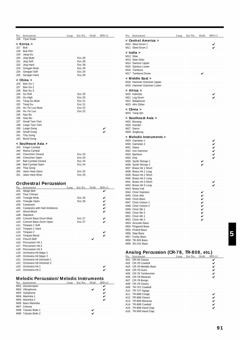
No. Instrument Loop Exc No. Hold SPD-11J16 Yyoo Dude
< Korea >J17 BukJ18 Buk RimJ19 Jang-GuJ20 Jing Mute Exc 28J21 Jing Soft Exc 28J22 Jing Hard Exc 28J23 Gengari Mute Exc 29J24 Gengari Soft Exc 29J25 Gengari Hard Exc 29
< China >J26 Ban Gu 1J27 Ban Gu 2J28 Ban Gu 3J29 Gu Roll Exc 20J30 Gu High Exc 20J31 Tang Gu Mute Exc 21J32 Tang Gu Exc 21J33 Hu Yin Luo Mute Exc 22J34 Hu Yin Luo Exc 22J35 Nao BoJ36 Xiao BoJ37 Small Tam-TamJ38 Large Tam-TamJ39 Large Gong ✔
J40 Small Gong ✔
J41 Tiny GongJ42 Bend Gong
< Southeast Asia >J43 Finger CymbalJ44 Rama CymbalJ45 Chenchen Closed Exc 23J46 Chenchen Open Exc 23J47 Bali Cymbal Closed Exc 24J48 Bali Cymbal Open Exc 24J49 Thai GongJ50 Jaws Harp Open Exc 25J51 Jaws Harp Wow Exc 25
Orchestral PercussionNo. Instrument Loop Exc No. Hold SPD-11o01 Sleigh Bell ✔
o02 Tree Chimeso03 Triangle Mute Exc 26 ✔
o04 Triangle Open Exc 26 ✔
o05 Castanets ✔
o06 Castanets with Hall Ambience ✔
o07 Wood Block ✔
o08 Slapsticko09 Concert Bass Drum Mute Exc 27 ✔
o10 Concert Bass Drum Open Exc 27 ✔
o11 Timpani 1 Softo12 Timpani 1 Hardo13 Timpani 2 ✔
o14 Timpani Bend ✔
o15 Church Bell ✔
o16 Percussion Hit 1o17 Percussion Hit 2o18 Percussion Hit 3o19 Orchestra Hit Major 1o20 Orchestra Hit Major 2o21 Orchestra Hit Diminish 1o22 Orchestra Hit Diminish 2o23 Orchestra Hit 1 ✔
o24 Orchestra Hit 2 ✔
Melodic Percussion/Melodic InstrumentsNo. Instrument Loop Exc No. Hold SPD-11M01 Glockenspiel ✔
M02 Vibraphone ✔ ✔
M03 Xylophone ✔
M04 Marimba 1 ✔
M05 Marimba 2 ✔
M06 Bass MarimbaM07 CelestaM08 Tubular Bells 1 ✔
M09 Tubular Bells 2 ✔
No. Instrument Loop Exc No. Hold SPD-11
< Central America >M10 Steel Drum 1 ✔
M11 Steel Drum 2 ✔
< India >M12 SitarM13 Sitar GlissM14 Santoor UpperM15 Santoor LowerM16 TamburaM17 Tambura Drone ✔
< Middle East >M18 Hammer Dulcimer UpperM19 Hammer Dulcimer Lower
< Africa >M20 Kalimba ✔
M21 Log Drum ✔
M22 BalaphoneM23 Afro Zither
< China >M24 Yang Qin
< Southeast Asia >M25 BonangM26 GenderM27 SaronM28 Angklung
< Melodic Instruments >M29 Gamelan 1 ✔
M30 Gamelan 2 ✔
M31 Glass ✔
M32 Iron Hammer ✔
M33 Bamboo ✔
M34 Drip ✔
M35 Synth Strings 1 ✔
M36 Synth Strings 2 ✔
M37 Brass Hit 1 ShortM38 Brass Hit 1 LongM39 Brass Hit 2 ShortM40 Brass Hit 2 LongM41 Brass Hit 3 Short ✔
M42 Brass Hit 3 Long ✔
M43 Brass FallM44 Choir Soprano ✔
M45 Choir Alto ✔
M46 Choir Bass ✔
M47 Choir Unison 1 ✔
M48 Choir Unison 2 ✔
M49 Choir 5th 1 ✔
M50 Choir 5th 2 ✔
M51 Choir 4th 1 ✔
M52 Choir 4th 2 ✔
M53 Acoustic BassM54 Fingered BassM55 Picked BassM56 Slap BassM57 Funky BassM58 TB-303 BassM59 SH-101 Bass
Analog Percussion (CR-78, TR-808, etc.)No. Instrument Loop Exc No. Hold SPD-11A01 DR-55 Claves ✔
A02 CR-78 Cowbell ✔
A03 CR-78 Metallic Beat ✔
A04 CR-78 Guiro ✔
A05 CR-78 Tambourine ✔
A06 CR-78 Maracas ✔
A07 CR-78 BongoA08 CR-78 ClavesA09 TR-707 CowbellA10 TR-727 AgogoA11 TR-808 Conga ✔
A12 TR-808 Claves ✔
A13 TR-808 Maracas ✔
A14 TR-808 Cowbell ✔
A15 TR-808 Hand Clap ✔
A16 TR-909 Hand Clap
91
1
2
3
4
5
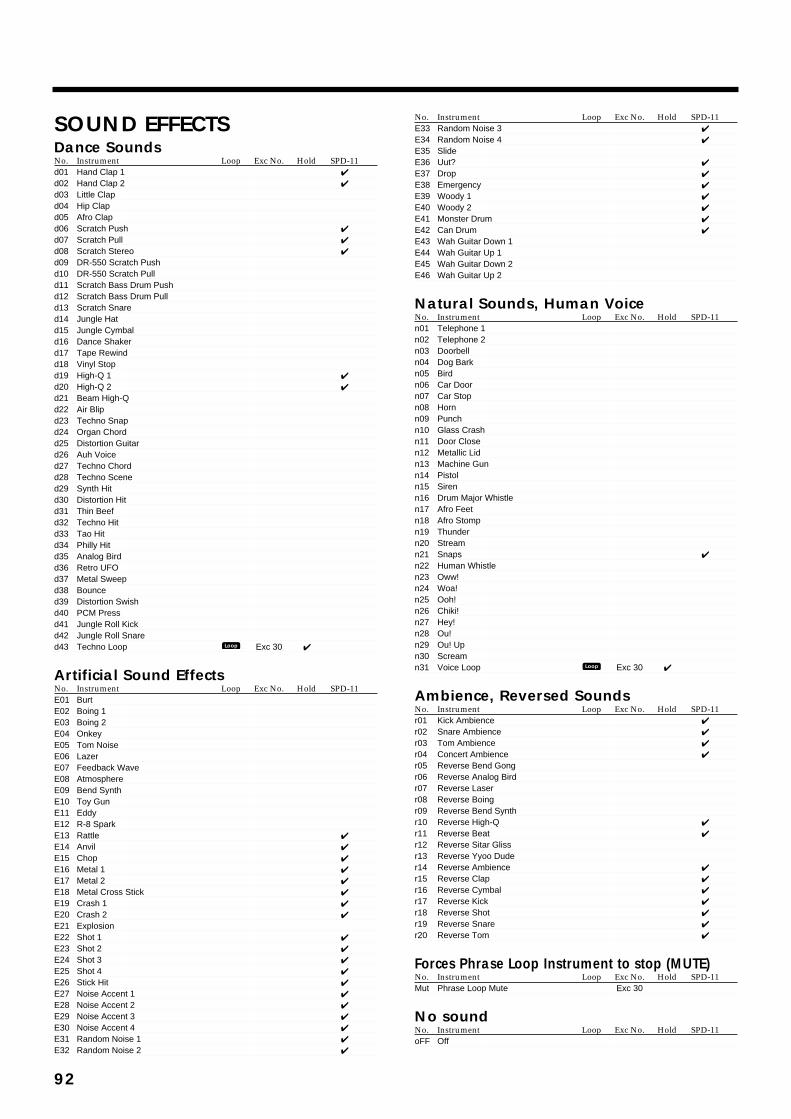
SOUND EFFECTSDance SoundsNo. Instrument Loop Exc No. Hold SPD-11d01 Hand Clap 1 ✔
d02 Hand Clap 2 ✔
d03 Little Clapd04 Hip Clapd05 Afro Clapd06 Scratch Push ✔
d07 Scratch Pull ✔
d08 Scratch Stereo ✔
d09 DR-550 Scratch Pushd10 DR-550 Scratch Pulld11 Scratch Bass Drum Pushd12 Scratch Bass Drum Pulld13 Scratch Snared14 Jungle Hatd15 Jungle Cymbald16 Dance Shakerd17 Tape Rewindd18 Vinyl Stopd19 High-Q 1 ✔
d20 High-Q 2 ✔
d21 Beam High-Qd22 Air Blipd23 Techno Snapd24 Organ Chordd25 Distortion Guitard26 Auh Voiced27 Techno Chordd28 Techno Scened29 Synth Hitd30 Distortion Hitd31 Thin Beefd32 Techno Hitd33 Tao Hitd34 Philly Hitd35 Analog Birdd36 Retro UFOd37 Metal Sweepd38 Bounced39 Distortion Swishd40 PCM Pressd41 Jungle Roll Kickd42 Jungle Roll Snared43 Techno Loop Exc 30 ✔
Artificial Sound EffectsNo. Instrument Loop Exc No. Hold SPD-11E01 BurtE02 Boing 1E03 Boing 2E04 OnkeyE05 Tom NoiseE06 LazerE07 Feedback WaveE08 AtmosphereE09 Bend SynthE10 Toy GunE11 EddyE12 R-8 SparkE13 Rattle ✔
E14 Anvil ✔
E15 Chop ✔
E16 Metal 1 ✔
E17 Metal 2 ✔
E18 Metal Cross Stick ✔
E19 Crash 1 ✔
E20 Crash 2 ✔
E21 ExplosionE22 Shot 1 ✔
E23 Shot 2 ✔
E24 Shot 3 ✔
E25 Shot 4 ✔
E26 Stick Hit ✔
E27 Noise Accent 1 ✔
E28 Noise Accent 2 ✔
E29 Noise Accent 3 ✔
E30 Noise Accent 4 ✔
E31 Random Noise 1 ✔
E32 Random Noise 2 ✔
No. Instrument Loop Exc No. Hold SPD-11E33 Random Noise 3 ✔
E34 Random Noise 4 ✔
E35 SlideE36 Uut? ✔
E37 Drop ✔
E38 Emergency ✔
E39 Woody 1 ✔
E40 Woody 2 ✔
E41 Monster Drum ✔
E42 Can Drum ✔
E43 Wah Guitar Down 1E44 Wah Guitar Up 1E45 Wah Guitar Down 2E46 Wah Guitar Up 2
Natural Sounds, Human VoiceNo. Instrument Loop Exc No. Hold SPD-11n01 Telephone 1n02 Telephone 2n03 Doorbelln04 Dog Barkn05 Birdn06 Car Doorn07 Car Stopn08 Hornn09 Punchn10 Glass Crashn11 Door Closen12 Metallic Lidn13 Machine Gunn14 Pistoln15 Sirenn16 Drum Major Whistlen17 Afro Feetn18 Afro Stompn19 Thundern20 Streamn21 Snaps ✔
n22 Human Whistlen23 Oww!n24 Woa!n25 Ooh!n26 Chiki!n27 Hey!n28 Ou!n29 Ou! Upn30 Screamn31 Voice Loop Exc 30 ✔
Ambience, Reversed SoundsNo. Instrument Loop Exc No. Hold SPD-11r01 Kick Ambience ✔
r02 Snare Ambience ✔
r03 Tom Ambience ✔
r04 Concert Ambience ✔
r05 Reverse Bend Gongr06 Reverse Analog Birdr07 Reverse Laserr08 Reverse Boingr09 Reverse Bend Synthr10 Reverse High-Q ✔
r11 Reverse Beat ✔
r12 Reverse Sitar Glissr13 Reverse Yyoo Duder14 Reverse Ambience ✔
r15 Reverse Clap ✔
r16 Reverse Cymbal ✔
r17 Reverse Kick ✔
r18 Reverse Shot ✔
r19 Reverse Snare ✔
r20 Reverse Tom ✔
Forces Phrase Loop Instrument to stop (MUTE)No. Instrument Loop Exc No. Hold SPD-11Mut Phrase Loop Mute Exc 30
No soundNo. Instrument Loop Exc No. Hold SPD-11oFF Off
Loop
Loop
92
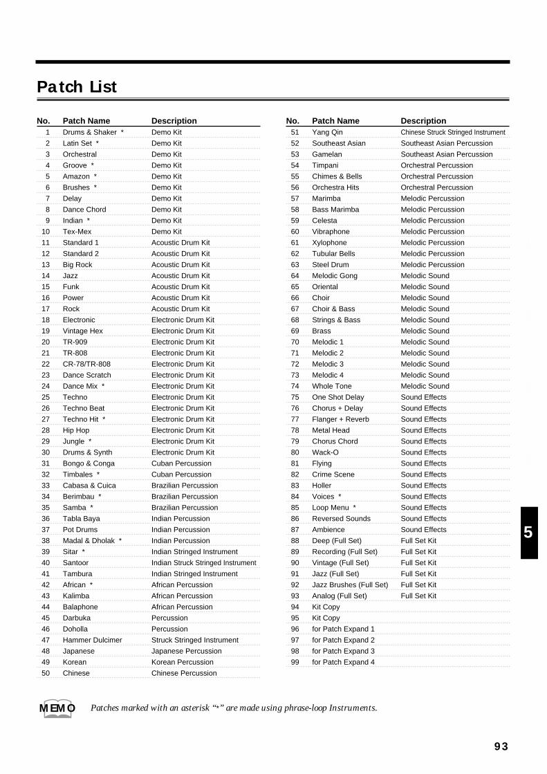
Patch List
93
1
2
3
4
5
No. Patch Name Description1 Drums & Shaker * Demo Kit
2 Latin Set * Demo Kit
3 Orchestral Demo Kit
4 Groove * Demo Kit
5 Amazon * Demo Kit
6 Brushes * Demo Kit
7 Delay Demo Kit
8 Dance Chord Demo Kit
9 Indian * Demo Kit
10 Tex-Mex Demo Kit
11 Standard 1 Acoustic Drum Kit
12 Standard 2 Acoustic Drum Kit
13 Big Rock Acoustic Drum Kit
14 Jazz Acoustic Drum Kit
15 Funk Acoustic Drum Kit
16 Power Acoustic Drum Kit
17 Rock Acoustic Drum Kit
18 Electronic Electronic Drum Kit
19 Vintage Hex Electronic Drum Kit
20 TR-909 Electronic Drum Kit
21 TR-808 Electronic Drum Kit
22 CR-78/TR-808 Electronic Drum Kit
23 Dance Scratch Electronic Drum Kit
24 Dance Mix * Electronic Drum Kit
25 Techno Electronic Drum Kit
26 Techno Beat Electronic Drum Kit
27 Techno Hit * Electronic Drum Kit
28 Hip Hop Electronic Drum Kit
29 Jungle * Electronic Drum Kit
30 Drums & Synth Electronic Drum Kit
31 Bongo & Conga Cuban Percussion
32 Timbales * Cuban Percussion
33 Cabasa & Cuica Brazilian Percussion
34 Berimbau * Brazilian Percussion
35 Samba * Brazilian Percussion
36 Tabla Baya Indian Percussion
37 Pot Drums Indian Percussion
38 Madal & Dholak * Indian Percussion
39 Sitar * Indian Stringed Instrument
40 Santoor Indian Struck Stringed Instrument
41 Tambura Indian Stringed Instrument
42 African * African Percussion
43 Kalimba African Percussion
44 Balaphone African Percussion
45 Darbuka Percussion
46 Doholla Percussion
47 Hammer Dulcimer Struck Stringed Instrument
48 Japanese Japanese Percussion
49 Korean Korean Percussion
50 Chinese Chinese Percussion
No. Patch Name Description51 Yang Qin Chinese Struck Stringed Instrument
52 Southeast Asian Southeast Asian Percussion
53 Gamelan Southeast Asian Percussion
54 Timpani Orchestral Percussion
55 Chimes & Bells Orchestral Percussion
56 Orchestra Hits Orchestral Percussion
57 Marimba Melodic Percussion
58 Bass Marimba Melodic Percussion
59 Celesta Melodic Percussion
60 Vibraphone Melodic Percussion
61 Xylophone Melodic Percussion
62 Tubular Bells Melodic Percussion
63 Steel Drum Melodic Percussion
64 Melodic Gong Melodic Sound
65 Oriental Melodic Sound
66 Choir Melodic Sound
67 Choir & Bass Melodic Sound
68 Strings & Bass Melodic Sound
69 Brass Melodic Sound
70 Melodic 1 Melodic Sound
71 Melodic 2 Melodic Sound
72 Melodic 3 Melodic Sound
73 Melodic 4 Melodic Sound
74 Whole Tone Melodic Sound
75 One Shot Delay Sound Effects
76 Chorus + Delay Sound Effects
77 Flanger + Reverb Sound Effects
78 Metal Head Sound Effects
79 Chorus Chord Sound Effects
80 Wack-O Sound Effects
81 Flying Sound Effects
82 Crime Scene Sound Effects
83 Holler Sound Effects
84 Voices * Sound Effects
85 Loop Menu * Sound Effects
86 Reversed Sounds Sound Effects
87 Ambience Sound Effects
88 Deep (Full Set) Full Set Kit
89 Recording (Full Set) Full Set Kit
90 Vintage (Full Set) Full Set Kit
91 Jazz (Full Set) Full Set Kit
92 Jazz Brushes (Full Set) Full Set Kit
93 Analog (Full Set) Full Set Kit
94 Kit Copy
95 Kit Copy
96 for Patch Expand 1
97 for Patch Expand 2
98 for Patch Expand 3
99 for Patch Expand 4
Patches marked with an asterisk “*” are made using phrase-loop Instruments.MEMO
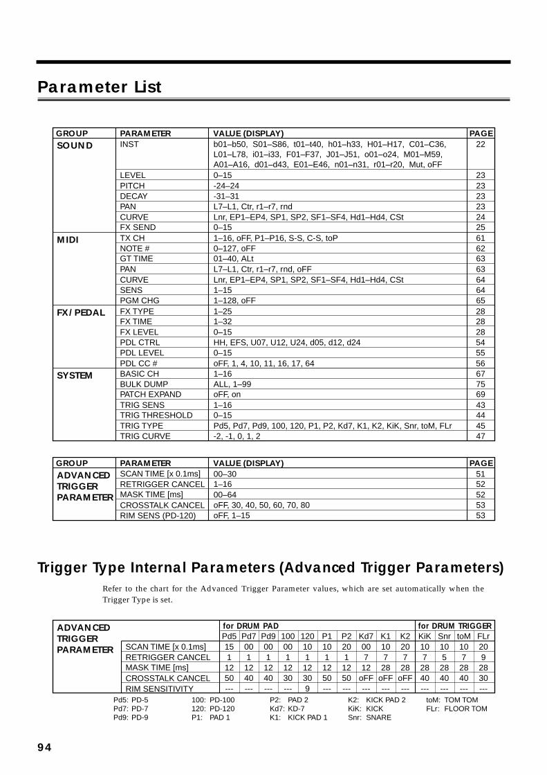
Parameter List
Trigger Type Internal Parameters (Advanced Trigger Parameters)Refer to the chart for the Advanced Trigger Parameter values, which are set automatically when theTrigger Type is set.
SOUND
MIDI
INST
LEVELPITCHDECAYPANCURVEFX SENDTX CHNOTE #GT TIMEPANCURVESENSPGM CHG
GROUP PARAMETER VALUE (DISPLAY) PAGE
FX/PEDAL FX TYPEFX TIMEFX LEVELPDL CTRLPDL LEVELPDL CC #
SYSTEM BASIC CHBULK DUMPPATCH EXPANDTRIG SENSTRIG THRESHOLDTRIG TYPETRIG CURVE
22
2323232324256162636364646528282854555667756943444547
b01–b50, S01–S86, t01–t40, h01–h33, H01–H17, C01–C36, L01–L78, i01–i33, F01–F37, J01–J51, o01–o24, M01–M59, A01–A16, d01–d43, E01–E46, n01–n31, r01–r20, Mut, oFF0–15-24–24-31–31L7–L1, Ctr, r1–r7, rnd
ADVANCEDTRIGGERPARAMETER
GROUP PARAMETER VALUE (DISPLAY) PAGE5152525353
00–301–1600–64oFF, 30, 40, 50, 60, 70, 80oFF, 1–15
Lnr, EP1–EP4, SP1, SP2, SF1–SF4, Hd1–Hd4, CSt
Lnr, EP1–EP4, SP1, SP2, SF1–SF4, Hd1–Hd4, CSt
0–151–16, oFF, P1–P16, S-S, C-S, toP0–127, oFF01–40, ALtL7–L1, Ctr, r1–r7, rnd, oFF
1–151–128, oFF1–251–320–15HH, EFS, U07, U12, U24, d05, d12, d240–15oFF, 1, 4, 10, 11, 16, 17, 641–16ALL, 1–99oFF, on1–160–15Pd5, Pd7, Pd9, 100, 120, P1, P2, Kd7, K1, K2, KiK, Snr, toM, FLr-2, -1, 0, 1, 2
SCAN TIME [x 0.1ms]RETRIGGER CANCELMASK TIME [ms]CROSSTALK CANCELRIM SENS (PD-120)
ADVANCEDTRIGGERPARAMETER
for DRUM TRIGGERfor DRUM PAD
10KiK
72840
10Snr
52840
10toM
72840
20FLr
92830
20K2
728
oFF
10K1
728
oFF
00Kd7
712
oFF
20P2
11250
10P1
11250
10120
11230
00100
11230
00Pd9
11240
00Pd7
11240
15Pd5
11250
SCAN TIME [x 0.1ms]RETRIGGER CANCELMASK TIME [ms]CROSSTALK CANCEL
--- --- --- ------------------9------------RIM SENSITIVITYPd5:Pd7:Pd9:
PD-5PD-7PD-9
100:120:P1:
PD-100PD-120PAD 1
P2:Kd7:K1:
PAD 2KD-7KICK PAD 1
K2:KiK:Snr:
KICK PAD 2KICKSNARE
toM:FLr:
TOM TOMFLOOR TOM
94
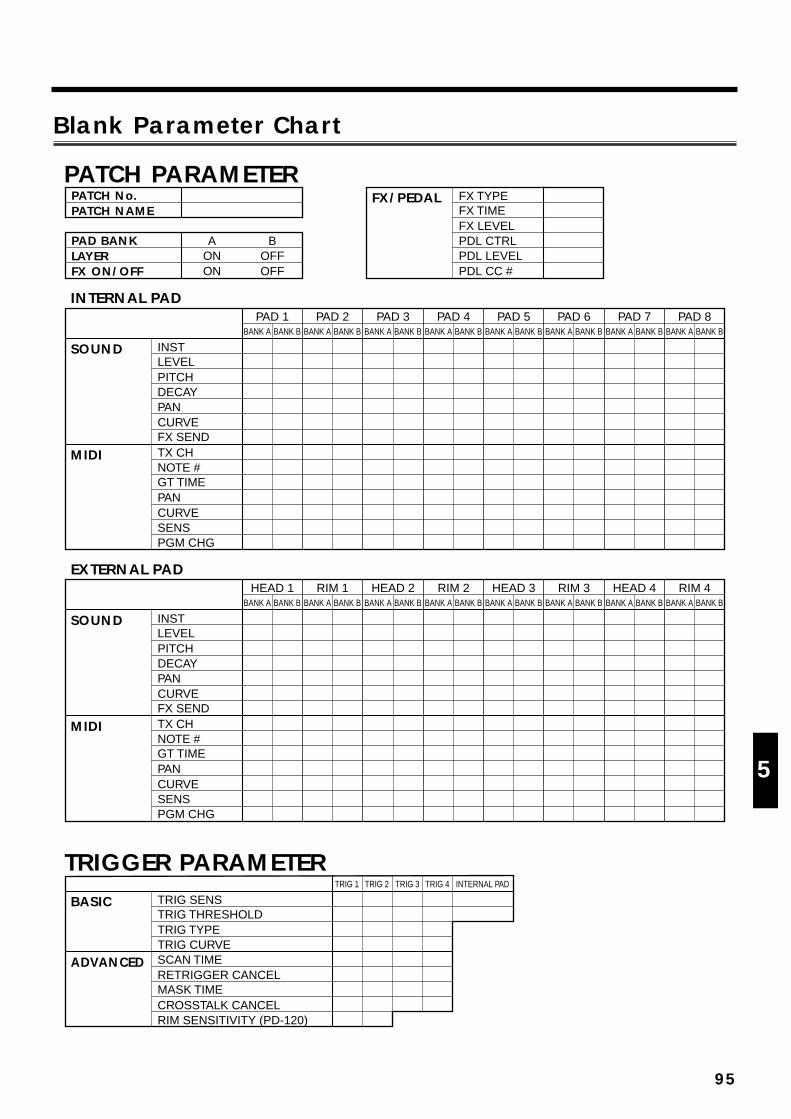
Blank Parameter Chart
SOUND
MIDI
INSTLEVELPITCHDECAYPANCURVEFX SENDTX CHNOTE #GT TIMEPANCURVESENSPGM CHG
PAD 1BANK A BANK B
PAD 2BANK A BANK B
PAD 3BANK A BANK B
PAD 4BANK A BANK B
PAD 5BANK A BANK B
PAD 6BANK A BANK B
PAD 7BANK A BANK B
PAD 8BANK A BANK B
SOUND
INTERNAL PAD
PAD BANKLAYERFX ON/OFF
AONON
BOFFOFF
PATCH No.PATCH NAME
FX/PEDAL FX TYPEFX TIMEFX LEVELPDL CTRLPDL LEVELPDL CC #
PATCH PARAMETER
EXTERNAL PAD
MIDI
INSTLEVELPITCHDECAYPANCURVEFX SENDTX CHNOTE #GT TIMEPANCURVESENSPGM CHG
HEAD 1BANK A BANK B
RIM 1BANK A BANK B
HEAD 2BANK A BANK B
RIM 2BANK A BANK B
HEAD 3BANK A BANK B
RIM 3BANK A BANK B
HEAD 4BANK A BANK B
RIM 4BANK A BANK B
BASIC
TRIGGER PARAMETER
ADVANCED
TRIG SENSTRIG THRESHOLDTRIG TYPETRIG CURVESCAN TIMERETRIGGER CANCELMASK TIMECROSSTALK CANCELRIM SENSITIVITY (PD-120)
TRIG 1 TRIG 2 TRIG 3 TRIG 4 INTERNAL PAD
95
1
2
3
4
5
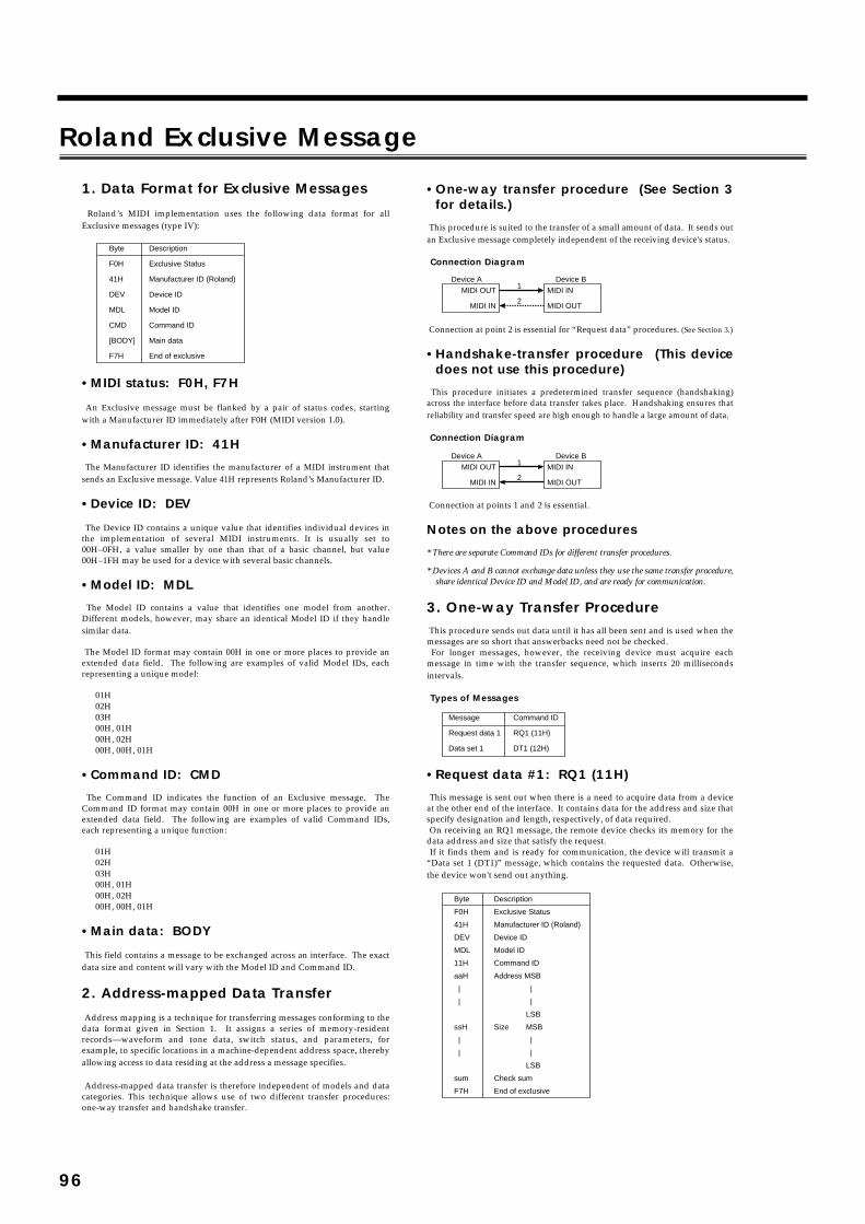
Roland Exclusive Messagefig.
1. Data Format for Exclusive Messages
Roland’s MIDI implementation uses the following data format for all Exclusive messages (type IV):
•MIDI status: F0H, F7H An Exclusive message must be flanked by a pair of status codes, starting with a Manufacturer ID immediately after F0H (MIDI version 1.0).
•Manufacturer ID: 41H
The Manufacturer ID identifies the manufacturer of a MIDI instrument that sends an Exclusive message. Value 41H represents Roland’s Manufacturer ID.
•Device ID: DEV
The Device ID contains a unique value that identifies individual devices in the implementation of several MIDI instruments. It is usually set to 00H–0FH, a value smaller by one than that of a basic channel, but value 00H–1FH may be used for a device with several basic channels.
•Model ID: MDL
The Model ID contains a value that identifies one model from another. Different models, however, may share an identical Model ID if they handle similar data.
The Model ID format may contain 00H in one or more places to provide an extended data field. The following are examples of valid Model IDs, each representing a unique model:
01H 02H 03H 00H, 01H 00H, 02H 00H, 00H, 01H
•Command ID: CMD
The Command ID indicates the function of an Exclusive message. The Command ID format may contain 00H in one or more places to provide an extended data field. The following are examples of valid Command IDs, each representing a unique function:
01H 02H 03H 00H, 01H 00H, 02H 00H, 00H, 01H
•Main data: BODY
This field contains a message to be exchanged across an interface. The exact data size and content will vary with the Model ID and Command ID.
2. Address-mapped Data Transfer Address mapping is a technique for transferring messages conforming to the data format given in Section 1. It assigns a series of memory-resident records—waveform and tone data, switch status, and parameters, for example, to specific locations in a machine-dependent address space, thereby allowing access to data residing at the address a message specifies. Address-mapped data transfer is therefore independent of models and data categories. This technique allows use of two different transfer procedures: one-way transfer and handshake transfer.
•One-way transfer procedure (See Section 3 for details.)
This procedure is suited to the transfer of a small amount of data. It sends out an Exclusive message completely independent of the receiving device's status.
Connection Diagram
Connection at point 2 is essential for “Request data” procedures. (See Section 3.)
•Handshake-transfer procedure (This device does not use this procedure)
This procedure initiates a predetermined transfer sequence (handshaking) across the interface before data transfer takes place. Handshaking ensures that reliability and transfer speed are high enough to handle a large amount of data.
Connection Diagram
Connection at points 1 and 2 is essential.
Notes on the above procedures
* There are separate Command IDs for different transfer procedures.
* Devices A and B cannot exchange data unless they use the same transfer procedure, share identical Device ID and Model ID, and are ready for communication.
3. One-way Transfer Procedure This procedure sends out data until it has all been sent and is used when the messages are so short that answerbacks need not be checked. For longer messages, however, the receiving device must acquire each message in time with the transfer sequence, which inserts 20 milliseconds intervals.
Types of Messages
•Request data #1: RQ1 (11H)
This message is sent out when there is a need to acquire data from a device at the other end of the interface. It contains data for the address and size that specify designation and length, respectively, of data required. On receiving an RQ1 message, the remote device checks its memory for the data address and size that satisfy the request. If it finds them and is ready for communication, the device will transmit a “Data set 1 (DT1)” message, which contains the requested data. Otherwise, the device won't send out anything.
Byte
F0H
41H
DEV
MDL
CMD
[BODY]
F7H
Description
Exclusive Status
Manufacturer ID (Roland)
Device ID
Model ID
Command ID
Main data
End of exclusive
MIDI OUT
MIDI IN
MIDI IN
MIDI OUT
Device A Device B1
2
MIDI OUT
MIDI IN
MIDI IN
MIDI OUT
Device A Device B1
2
Message
Request data 1
Data set 1
Command ID
RQ1 (11H)
DT1 (12H)
Byte
F0H
41H
DEV
MDL
11H
aaH
|
|
ssH
|
|
sum
F7H
Description
Exclusive Status
Manufacturer ID (Roland)
Device ID
Model ID
Command ID
Address MSB
|
|
LSB
Size MSB
|
|
LSB
Check sum
End of exclusive
96
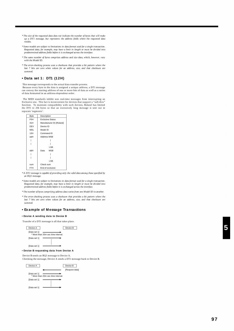
fig.
* The size of the requested data does not indicate the number of bytes that will make up a DT1 message, but represents the address fields where the requested data resides.
* Some models are subject to limitations in data format used for a single transaction. Requested data, for example, may have a limit in length or must be divided into predetermined address fields before it is exchanged across the interface.
* The same number of bytes comprises address and size data, which, however, vary with the Model ID.
* The error-checking process uses a checksum that provides a bit pattern where the last 7 bits are zero when values for an address, size, and that checksum are summed.
•Data set 1: DT1 (12H)
This message corresponds to the actual data transfer process. Because every byte in the data is assigned a unique address, a DT1 message can convey the starting address of one or more bits of data as well as a series of data formatted in an address-dependent order.
The MIDI standards inhibit non real-time messages from interrupting an Exclusive one. This fact is inconvenient for devices that support a “soft-thru” function. To maintain compatibility with such devices, Roland has limited the DT1 to 256 bytes so that an excessively long message is sent out in separate ‘segments’.
* A DT1 message is capable of providing only the valid data among those specified by an RQ1 message.
* Some models are subject to limitations in data format used for a single transaction. Requested data, for example, may have a limit in length or must be divided into predetermined address fields before it is exchanged across the interface.
* The number of bytes comprising address data varies from one Model ID to another.
* The error-checking process uses a checksum that provides a bit pattern where the last 7 bits are zero when values for an address, size, and that checksum are summed.
•Example of Message Transactions
•Device A sending data to Device B
Transfer of a DT1 message is all that takes place.
•Device B requesting data from Device A
Device B sends an RQ1 message to Device A. Checking the message, Device A sends a DT1 message back to Device B.
Byte
F0H
41H
DEV
MDL
12H
aaH
|
|
ddH
|
|
sum
F7H
Description
Exclusive Status
Manufacturer ID (Roland)
Device ID
Model ID
Command ID
Address MSB
|
|
LSB
Data MSB
|
|
LSB
Check sum
End of exclusive
Device A Device B
[Data set 1]
[Data set 1]
[Data set 1]
* More than 20m sec time interval.
[Request data]
[Data set 1]
[Data set 1]
* More than 20m sec time interval.[Data set 1]
Device A Device B
97
1
2
3
4
5

TOTAL PERCUSSION PAD Date: Dec. 4 1997
Model SPD-20 Version: 1.00
MIDI Implementation
98
1.TRANSMITTED DATA
[Channel Voice Message]
(1) Note offStatus Second Third9nH kkH 00Hn = MIDI Channel: 0H–FH (ch.1–ch.16)kk = Note number: 00H–7FH (0–127)
(2) Note onStatus Second Third9nH kkH vvHn = MIDI Channel: 0H–FH (ch.1–ch.16)kk = Note number: 00H–7FH (0–127)vv = Velocity: 01H–7FH (1–127)
The SPD-20 transmits through the MIDI Channels set to each Pad’s Transmit Channel (TXCH). However, there is no transmission if the Transmit Channel is set to P1–P16, S-S, C-S,or toP.When the Gate Time is set to 01–40, after Note On is transmitted, Note Off is transmittedafter the set time has elapsed. However, if a new sound is produced by the same Padbefore Note Off is transmitted, then Note Off is transmitted at that time.With Gate Time set to ALt, Note On and Note Off messages are alternately transmittedwhen you strike the Pad. However, when switching Patches, When the Layer function is on, settings for both Bank A and Bank B are transmitted.
(3) Polyphonic Key PressureStatus Second ThirdAnH kkH vvHn = MIDI Channel: 0H–FH (ch.1–ch.16)kk = Note number: 00H–127H (0–127)vv = Value: 00H, 7FH (0, 127)
These are transmitted via the MIDI Channel that is set to each Pad’s Transmit Channel.However, if the Transmit Channel is set to P1–P16, S-S, C-S, or toP, the settings are nottransmitted.This message is transmitted with value 7FH when grab the rim of the pad or value 00Hwhen release the rim. Note number to be transferred is content of the head/rim of grabbedpad.When the “SOUND” is set from “H**”, the note number of the head, rim, note number ofhead minus 2, note number of head minus 4, note number of rim minus 2, note number ofrim minus 4 are transferred.When the “LAYER” is set at “ON”, the note number of “BANK A” and “BANK B” aretransmitted.
(4) Control Change
Modulation Depth (Controller number 1)Status Second ThirdBnH 01H vvH
Foot Control (Controller number 4)Status Second ThirdBnH 04H vvH
Expression (Controller number 11)Status Second ThirdBnH 0BH vvH
General purpose controller 1 (Controller number 16)Status Second ThirdBnH 10H vvH
General purpose controller 2 (Controller number 17)Status Second ThirdBnH 11H vvHn = MIDI channel: 0H–0FH (ch.1–ch.16)vv = Parameter Value: 00H–7FH (0–127)
This transmits the Hi-Hat Controller position message as one of the Control Messages setin PDL CC#.When the Footswitch function is set as a hold pedal, then if the pedal is pressed, 7FH istransmitted; when the pedal is released, 00H is transmitted.It is transmitted via the MIDI Channel set to the Basic Channel.
Hold1 (Controller number 64)Status Second ThirdBnH 40H vvHn = MIDI channel: 0H–0FH (ch.1–ch.16)vv = Parameter Value: 00H–7FH (0–127)
This transmits the Hi-Hat Controller position message as one of the Control Messages setin PDL CC#.It is transmitted via the MIDI Channel set to the Basic Channel.
Panpot (Controller number 10)Status Second ThirdBnH 0AH vvHn = MIDI channel: 0H–0FH (ch.1–ch.16)vv = Panpot: 00H–7FH (0–127)
This transmits the Hi-Hat Controller position message as one of the Control Messages setin PDL CC#.It is transmitted via the MIDI Channel set to the Basic Channel.These are transmitted via the MIDI Channel that is set to each Pad’s Transmit Channel.However, if the Transmit Channel is set to P1–P16, S-S, C-S, or toP, the settings are nottransmitted.When the Pad is struck, the Panpot value corresponding to the MIDI PAN set to the Pad istransmitted.The Panpot message is not transmitted when the Transmit Channel and the Panpot value
of a Pad that is tapped are the same as those of the most recently tapped Pad.
The Panpot valueMIDI PAN vv
L7 0L6 9L5 18L4 27L3 36L2 45L1 54Ctr 64R1 73R2 82R3 91R4 100R5 109R6 118R7 127rnd one of upper value
(5) Program ChangeStatus SecondCnH ppHn = MIDI channel: 0H–FH (ch.1–ch.16)pp = Program number: 00H–7FH (prog.1–prog.128)
With the Transmit Channel set to 1–16, when you switch Patches, the Transmit Channeland Program Changes set to each of the Pads in Banks A and B are transmitted.With the Transmit Channel set to P1–P16, when you strike Pads, the Transmit Channel andProgram Changes set to each of the Pads in Banks A and B are transmitted.
[System Exclusive Message]StatusF0H: System ExclusiveF7H: EOX (End Of Exclusive)
With the SPD-20, the System Exclusive Message can be used to transmit Bulk Dump ofpatch data, instrument data, system data, chain data and sequence data.For details refer to “3. Exclusive Communications” and “Roland Exclusive Message.”
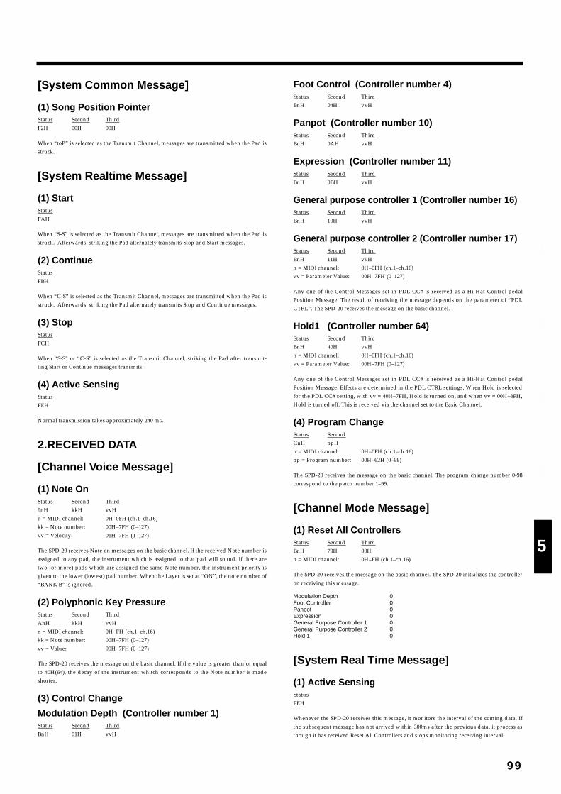
[System Common Message]
(1) Song Position PointerStatus Second ThirdF2H 00H 00H
When “toP” is selected as the Transmit Channel, messages are transmitted when the Pad isstruck.
[System Realtime Message]
(1) StartStatusFAH
When “S-S” is selected as the Transmit Channel, messages are transmitted when the Pad isstruck. Afterwards, striking the Pad alternately transmits Stop and Start messages.
(2) ContinueStatusFBH
When “C-S” is selected as the Transmit Channel, messages are transmitted when the Pad isstruck. Afterwards, striking the Pad alternately transmits Stop and Continue messages.
(3) StopStatusFCH
When “S-S” or “C-S” is selected as the Transmit Channel, striking the Pad after transmit-ting Start or Continue messages transmits.
(4) Active SensingStatusFEH
Normal transmission takes approximately 240 ms.
2.RECEIVED DATA
[Channel Voice Message]
(1) Note OnStatus Second Third9nH kkH vvHn = MIDI channel: 0H–0FH (ch.1–ch.16)kk = Note number: 00H–7FH (0–127)vv = Velocity: 01H–7FH (1–127)
The SPD-20 receives Note on messages on the basic channel. If the received Note number isassigned to any pad, the instrument which is assigned to that pad will sound. If there aretwo (or more) pads which are assigned the same Note number, the instrument priority isgiven to the lower (lowest) pad number. When the Layer is set at “ON”, the note number of“BANK B” is ignored.
(2) Polyphonic Key PressureStatus Second ThirdAnH kkH vvHn = MIDI channel: 0H–FH (ch.1–ch.16)kk = Note number: 00H–7FH (0–127)vv = Value: 00H–7FH (0–127)
The SPD-20 receives the message on the basic channel. If the value is greater than or equalto 40H(64), the decay of the instrument whitch corresponds to the Note number is madeshorter.
(3) Control Change
Modulation Depth (Controller number 1)Status Second ThirdBnH 01H vvH
Foot Control (Controller number 4)Status Second ThirdBnH 04H vvH
Panpot (Controller number 10)Status Second ThirdBnH 0AH vvH
Expression (Controller number 11)Status Second ThirdBnH 0BH vvH
General purpose controller 1 (Controller number 16)Status Second ThirdBnH 10H vvH
General purpose controller 2 (Controller number 17)Status Second ThirdBnH 11H vvHn = MIDI channel: 0H–0FH (ch.1–ch.16)vv = Parameter Value: 00H–7FH (0–127)
Any one of the Control Messages set in PDL CC# is received as a Hi-Hat Control pedalPosition Message. The result of receiving the message depends on the parameter of “PDLCTRL”. The SPD-20 receives the message on the basic channel.
Hold1 (Controller number 64)Status Second ThirdBnH 40H vvHn = MIDI channel: 0H–0FH (ch.1–ch.16)vv = Parameter Value: 00H–7FH (0–127)
Any one of the Control Messages set in PDL CC# is received as a Hi-Hat Control pedalPosition Message. Effects are determined in the PDL CTRL settings. When Hold is selectedfor the PDL CC# setting, with vv = 40H–7FH, Hold is turned on, and when vv = 00H–3FH,Hold is turned off. This is received via the channel set to the Basic Channel.
(4) Program ChangeStatus SecondCnH ppHn = MIDI channel: 0H–0FH (ch.1–ch.16)pp = Program number: 00H–62H (0–98)
The SPD-20 receives the message on the basic channel. The program change number 0-98correspond to the patch number 1–99.
[Channel Mode Message]
(1) Reset All ControllersStatus Second ThirdBnH 79H 00Hn = MIDI channel: 0H–FH (ch.1–ch.16)
The SPD-20 receives the message on the basic channel. The SPD-20 initializes the controlleron receiving this message.
Modulation Depth 0Foot Controller 0Panpot 0Expression 0General Purpose Controller 1 0General Purpose Controller 2 0Hold 1 0
[System Real Time Message]
(1) Active SensingStatusFEH
Whenever the SPD-20 receives this message, it monitors the interval of the coming data. Ifthe subsequent message has not arrived within 300ms after the previous data, it process asthough it has received Reset All Controllers and stops monitoring receiving interval.
99
1
2
3
4
5
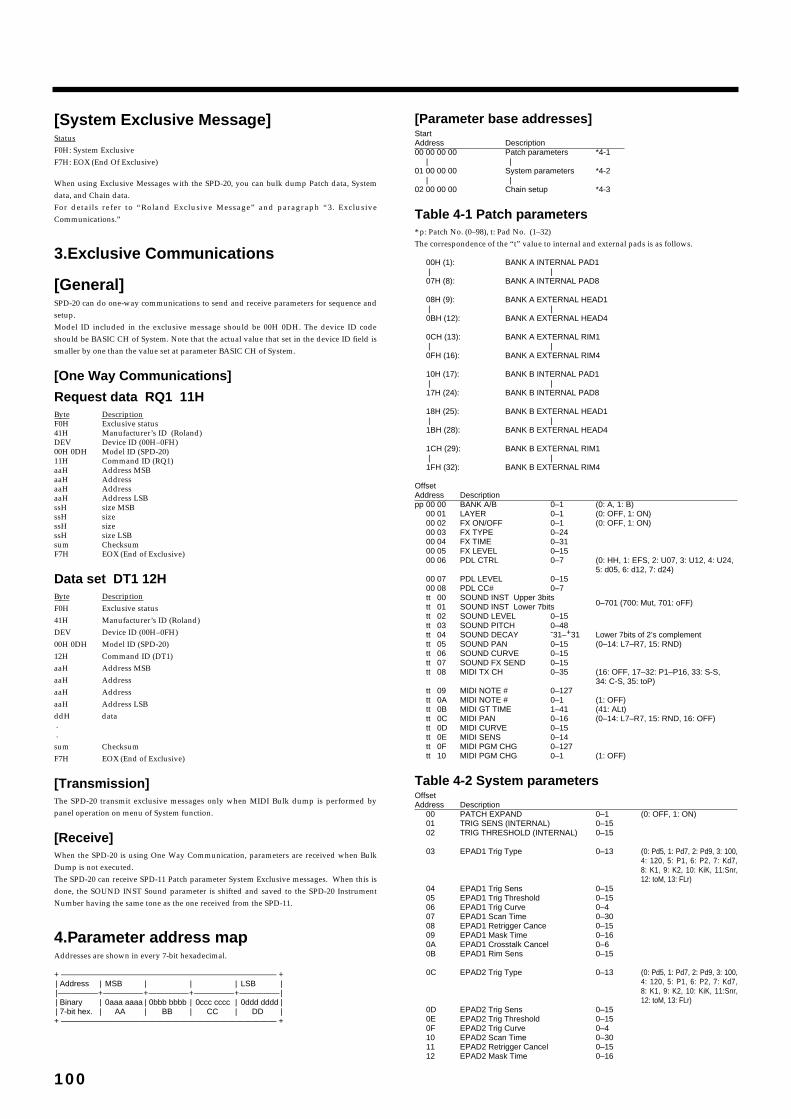
[System Exclusive Message]StatusF0H: System ExclusiveF7H: EOX (End Of Exclusive)
When using Exclusive Messages with the SPD-20, you can bulk dump Patch data, Systemdata, and Chain data.For details refer to “Roland Exclusive Message” and paragraph “3. ExclusiveCommunications.”
3.Exclusive Communications
[General]SPD-20 can do one-way communications to send and receive parameters for sequence andsetup.Model ID included in the exclusive message should be 00H 0DH. The device ID codeshould be BASIC CH of System. Note that the actual value that set in the device ID field issmaller by one than the value set at parameter BASIC CH of System.
[One Way Communications]
Request data RQ1 11HByte DescriptionF0H Exclusive status41H Manufacturer’s ID (Roland)DEV Device ID (00H–0FH)00H 0DH Model ID (SPD-20)11H Command ID (RQ1)aaH Address MSBaaH AddressaaH AddressaaH Address LSBssH size MSBssH sizessH sizessH size LSBsum ChecksumF7H EOX (End of Exclusive)
Data set DT1 12HByte DescriptionF0H Exclusive status41H Manufacturer’s ID (Roland)DEV Device ID (00H–0FH)00H 0DH Model ID (SPD-20)12H Command ID (DT1)aaH Address MSBaaH AddressaaH Address aaH Address LSBddH data..sum ChecksumF7H EOX (End of Exclusive)
[Transmission]The SPD-20 transmit exclusive messages only when MIDI Bulk dump is performed bypanel operation on menu of System function.
[Receive]When the SPD-20 is using One Way Communication, parameters are received when BulkDump is not executed.The SPD-20 can receive SPD-11 Patch parameter System Exclusive messages. When this isdone, the SOUND INST Sound parameter is shifted and saved to the SPD-20 InstrumentNumber having the same tone as the one received from the SPD-11.
4.Parameter address mapAddresses are shown in every 7-bit hexadecimal.
+ ——————————————————————————— +| Address | MSB | | | LSB ||—————+—————+—————+—————+————— || Binary | 0aaa aaaa | 0bbb bbbb | 0ccc cccc | 0ddd dddd || 7-bit hex. | AA | BB | CC | DD |+ ——————————————————————————— +
[Parameter base addresses]StartAddress Description00 00 00 00 Patch parameters *4-1
| |01 00 00 00 System parameters *4-2
| |02 00 00 00 Chain setup *4-3
Table 4-1 Patch parameters* p: Patch No. (0–98), t: Pad No. (1–32)The correspondence of the “t” value to internal and external pads is as follows.
00H (1): BANK A INTERNAL PAD1| |
07H (8): BANK A INTERNAL PAD8
08H (9): BANK A EXTERNAL HEAD1| |
0BH (12): BANK A EXTERNAL HEAD4
0CH (13): BANK A EXTERNAL RIM1| |
0FH (16): BANK A EXTERNAL RIM4
10H (17): BANK B INTERNAL PAD1| |
17H (24): BANK B INTERNAL PAD8
18H (25): BANK B EXTERNAL HEAD1| |
1BH (28): BANK B EXTERNAL HEAD4
1CH (29): BANK B EXTERNAL RIM1| |
1FH (32): BANK B EXTERNAL RIM4
OffsetAddress Descriptionpp 00 00 BANK A/B 0–1 (0: A, 1: B)
00 01 LAYER 0–1 (0: OFF, 1: ON)00 02 FX ON/OFF 0–1 (0: OFF, 1: ON)00 03 FX TYPE 0–2400 04 FX TIME 0–3100 05 FX LEVEL 0–1500 06 PDL CTRL 0–7 (0: HH, 1: EFS, 2: U07, 3: U12, 4: U24,
5: d05, 6: d12, 7: d24)00 07 PDL LEVEL 0–1500 08 PDL CC# 0–7tt 00 SOUND INST Upper 3bits
0–701 (700: Mut, 701: oFF)tt 01 SOUND INST Lower 7bitstt 02 SOUND LEVEL 0–15tt 03 SOUND PITCH 0–48tt 04 SOUND DECAY -31–+31 Lower 7bits of 2’s complementtt 05 SOUND PAN 0–15 (0–14: L7–R7, 15: RND)tt 06 SOUND CURVE 0–15tt 07 SOUND FX SEND 0–15tt 08 MIDI TX CH 0–35 (16: OFF, 17–32: P1–P16, 33: S-S,
34: C-S, 35: toP)tt 09 MIDI NOTE # 0–127tt 0A MIDI NOTE # 0–1 (1: OFF)tt 0B MIDI GT TIME 1–41 (41: ALt) tt 0C MIDI PAN 0–16 (0–14: L7–R7, 15: RND, 16: OFF)tt 0D MIDI CURVE 0–15tt 0E MIDI SENS 0–14tt 0F MIDI PGM CHG 0–127 tt 10 MIDI PGM CHG 0–1 (1: OFF)
Table 4-2 System parametersOffsetAddress Description
00 PATCH EXPAND 0–1 (0: OFF, 1: ON)01 TRIG SENS (INTERNAL) 0–1502 TRIG THRESHOLD (INTERNAL) 0–15
03 EPAD1 Trig Type 0–13 (0: Pd5, 1: Pd7, 2: Pd9, 3: 100,4: 120, 5: P1, 6: P2, 7: Kd7,8: K1, 9: K2, 10: KiK, 11:Snr,12: toM, 13: FLr)
04 EPAD1 Trig Sens 0–1505 EPAD1 Trig Threshold 0–1506 EPAD1 Trig Curve 0–407 EPAD1 Scan Time 0–3008 EPAD1 Retrigger Cance 0–1509 EPAD1 Mask Time 0–160A EPAD1 Crosstalk Cancel 0–60B EPAD1 Rim Sens 0–15
0C EPAD2 Trig Type 0–13 (0: Pd5, 1: Pd7, 2: Pd9, 3: 100,4: 120, 5: P1, 6: P2, 7: Kd7,8: K1, 9: K2, 10: KiK, 11:Snr,12: toM, 13: FLr)
0D EPAD2 Trig Sens 0–150E EPAD2 Trig Threshold 0–150F EPAD2 Trig Curve 0–410 EPAD2 Scan Time 0–3011 EPAD2 Retrigger Cancel 0–1512 EPAD2 Mask Time 0–16
100
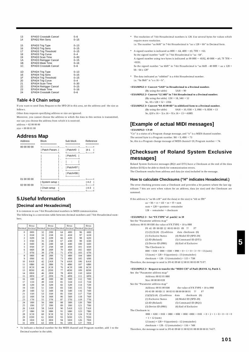
13 EPAD2 Crosstalk Cancel 0–614 EPAD2 Rim Sens 0–15
15 EPAD3 Trig Type 0–1316 EPAD3 Trig Sens 0–1517 EPAD3 Trig Threshold 0–1518 EPAD3 Trig Curve 0–419 EPAD3 Scan Time 0–301A EPAD3 Retrigger Cancel 0–151B EPAD3 Mask Time 0–161C EPAD3 Crosstalk Cancel 0–6
1D EPAD4 Trig Type 0–131E EPAD4 Trig Sens 0–151F EPAD4 Trig Threshold 0–1520 EPAD4 Trig Curve 0–421 EPAD4 Scan Time 0–3022 EPAD4 Retrigger Cancel 0–1523 EPAD4 Mask Time 0–1624 EPAD4 Crosstalk Cancel 0–6
Table 4-3 Chain setupIf you want to send Data Request to the SPD-20 in this area, set the address and the size asfollows.Other data requests specifying address or size are ignored.Moreover, you cannot choose the address to which the data in this section is transmitted,nor can you choose the address from which it is received.address = 02 00 00 00size = 00 00 01 00
Address MapAddress Block Sub block Reference========== =========== ========== =========00 00 00 00 +——————-+........ +————–+........+——-+
| Patch Param. | | Patch#0 | |4-1 |+——————-+. +————–+........+——-+| | . | Patch#1 || | . +————–+| | . | : || | . +————–+| | . | Patch#97 || | . +————–+| | . | Patch#98 || | +————–+
01 00 00 00 +——————-+..................................... +——-+| System setup | | 4-2 |
02 00 00 00 +——————-+..................................... +——-+| Chain setup | | 4-3 |+——————-+..................................... +——-+
5.Useful Information[Decimal and Hexadecimal]It is common to use 7-bit Hexadecimal numbers in MIDI communication.The following is a conversion table between decimal numbers and 7-bit Hexadecimal num-bers.fig.
* To indicate a decimal number for the MIDI channel and Program number, add 1 to theDecimal number in the table.
* The resolution of 7-bit Hexadecimal numbers is 128. Use several bytes for values whichrequire more resolution. i.e. The number “aa bbH” in 7-bit Hexadecimal is “aa x 128 + bb” in Decimal form.
* A signed number is indicated as 00H = -64, 40H = ±0, 7FH = +63. So the signed number “aaH” in 7-bit Hexadecimal is “aa - 64”. A signed number using two bytes is indicated as 00 00H = -8192, 40 00H = ±0, 7F 7FH =+8191.So the signed number “aa bbH” in 7-bit Hexadecimal is “aa bbH - 40 00H = aa x 128 +bb - 64 x 128”
* The data indicated as “nibbled” is a 4-bit Hexadecimal number.i.e. “0a 0bH” is “a x 16 + b”.
<EXAMPLE 1> Convert “5AH” in Hexadecimal to a Decimal number.
(By using the table) 5AH = 90 <EXAMPLE 2> Convert “12 34H” in 7-bit Hexadecimal to a Decimal number.
(By using the table) 12H = 18, 34H = 52 So, 18 x 128 + 52 = 2356
<EXAMPLE 3> Convert “0A 03 09 0D” in nibblized form to a Decimal number.
(By using the table) 0AH = 10, 03H = 3, 09H = 9, 0DH = 13So, {(10 x 16 + 3) x 16 + 9} x 16 + 13 = 41885
[Example of actual MIDI messages]<EXAMPLE> C9 49
”Cn” is a status of a Program change message, and “n” is a MIDI channel number.The second byte is a Program number. 9H = 9, 49H = 73 So, this is a Program change message of MIDI channel=10, Program number = 74.
[Checksum of Roland System Exclusivemessages]Roland System Exclusive messages (RQ1 and DT1) have a Checksum at the end of the data(before EOX) to be able to check for communication errors.The Checksum results from address and data (or size) included in the message.
How to calculate Checksums (“H” indicates Hexadecimal.)The error checking process uses a Checksum and provides a bit pattern where the last sig-nificant 7 bits are zero when values for an address, data (or size) and the Checksum aresummed.
If the address is “aa bb ccH” and the data( or the size) is “dd ee ffH”aa + bb + cc + dd + ee + ff = sumsum ÷ 128 = quotient—remainder128 - remainder = checksum
<EXAMPLE 1> Set “FX TYPE” of patch2 to 10
See the “Parameter address map”Address: 00 01 00 03H the value of FX TYPE = 10 is 09H
F0 41 09 00 0D 12 00 01 00 03 09 ?? F7(1) (2) (3) (4) (5) address data checksum (6)(1) Exclusive Status (4) Model ID (SPD-20) (2) ID (Roland) (5) Command ID (DT1)(3) Device ID (09H) (6) End of ExclusiveThe Checksum is:00H + 01H + 00H + 03H + 09H = 0 + 1 + 0 + 3 + 9 = 13 (sum)13 (sum) ÷ 128 = 0 (quotient)—13 (remainder)checksum = 128 - 13 (remainder) = 115 = 73H
Therefore, the message to send is: F0 41 09 60 12 00 01 00 03 09 73 F7.
<EXAMPLE 2> Request to transfer the “MIDI CH” of Pad1 (BANK A), Patch 3.
See the “Parameter address map”Address: 00 02 01 08H Size: 00 00 00 01H
See the “Parameter address map”Address: 00 01 00 03H the value of FX TYPE = 10 is 09HF0 41 09 00 0D 11 00 02 01 08 00 00 00 01 ?? F7(1)(2)(3) (4) (5) address data checksum (6)(1) Exclusive Status (4) Model ID (SPD-20)(2) ID (Roland) (5) Command ID (RQ1)(3) Device ID (09H) (6) End of Exclusive
The Checksum is:00H + 02H + 01H + 08H + 00H + 00H +00H + 01H = 0 + 2 + 1 + 8 + 0 + 0 + 0+ 1 = 12 (sum)12 (sum) ÷ 128 = 0 (quotient)—12 (remainder)checksum = 128 - 12 (remainder) = 116 = 74H
Therefore, the message to send is: F0 41 09 60 11 00 02 01 08 00 00 00 01 74 F7.
0123456789
10111213141516171819202122232425262728293031
00H01H02H03H04H05H06H07H08H09H
0AH0BH0CH0DH0EH0FH10H11H12H13H14H15H16H17H18H19H
1AH1BH1CH1DH1EH1FH
Decimal Decimal Decimal DecimalHexa-
decimalHexa-
decimalHexa-
decimalHexa-
decimal
3233343536373839404142434445464748495051525354555657585960616263
20H21H22H23H24H25H26H27H28H29H
2AH2BH2CH2DH2EH2FH30H31H32H33H34H35H36H37H38H39H
3AH3BH3CH3DH3EH3FH
6465666768697071727374757677787980818283848586878889909192939495
40H41H42H43H44H45H46H47H48H49H
4AH4BH4CH4DH4EH4FH50H51H52H53H54H55H56H57H58H59H
5AH5BH5CH5DH5EH5FH
96979899
100101102103104105106107108109110111112113114115116117118119120121122123124125126127
60H61H62H63H64H65H66H67H68H69H
6AH6BH6CH6DH6EH6FH70H71H72H73H74H75H76H77H78H79H
7AH7BH7CH7DH7EH7FH
101
1
2
3
4
5

MIDI Implementation Chart
102
Function...
BasicChannel
Mode
NoteNumber :
Velocity
AfterTouch
Pitch Bend
ControlChange
ProgramChange
System Exclusive
SystemCommon
SystemReal Time
AuxMessage
Notes
Transmitted Recognized Remarks
DefaultChanged
DefaultMessagesAltered
True Voice
Note ONNote OFF
Key'sCh's
1
4
1011
1617
64
121
: True #
: Song Pos: Song Sel: Tune
: Clock: Commands
: Local ON/OFF: All Notes OFF: Active Sense: System Reset
Off, 1–16Off, 1–16
*1*1
*2
*3
*3
*3*3
*3*3
*3 *4
*2
*3
*3
*3*3
*3*3
*3
Mode 3X
O 9n v = 1–127X
Off, 0–127
0, 127X
X
X
O
XX
XX
X
X
X
O
XX
XX
O
O
O *1Off, 0–127
O
X *1XX
XX *1
XXOX
1–161–16
Mode 3X
O 9b v = 1–127X
Off, 0–127
O 0, 127X
X
O0–98
O
XXX
XX
XXOX
Modulation
Foot
PanExpression
General Purpose 1General Purpose 2
Hold 1
Reset all controllers
* 1 Can be set and stored for each pad.* 2 Common to “Transmitted” and “Recognized.”* 3 Select one to use as the Hi-hat Control pedal.* 4 Transmitted when Footswitch is set to “Hold pedal.”
TOTAL PERCUSSION PAD
Model SPD-20
Date : Dec. 4, 1997
Version : 1.00MIDI Implementation Chart
**************
**************
Mode 1 : OMNI ON, POLYMode 3 : OMNI OFF, POLY
Mode 2 : OMNI ON, MONOMode 4 : OMNI OFF, MONO
O : YesX : No
Memorized(Non-volatile)
n = Pad ch.b = Basic ch.9n v = 0
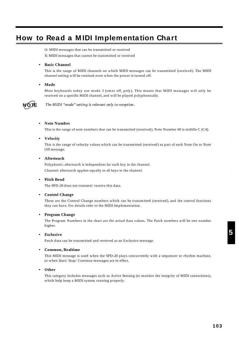
How to Read a MIDI Implementation ChartO: MIDI messages that can be transmitted or received
X: MIDI messages that cannot be transmitted or received
• Basic ChannelThis is the range of MIDI channels on which MIDI messages can be transmitted (received). The MIDIchannel setting will be retained even when the power is turned off.
• ModeMost keyboards today use mode 3 (omni off, poly). This means that MIDI messages will only bereceived on a specific MIDI channel, and will be played polyphonically.
The MIDI “mode” setting is relevant only to reception.
• Note NumberThis is the range of note numbers that can be transmitted (received). Note Number 60 is middle C (C4).
• VelocityThis is the range of velocity values which can be transmitted (received) as part of each Note On or NoteOff message.
• AftertouchPolyphonic: aftertouch is independent for each key in the channel.
Channel: aftertouch applies equally to all keys in the channel.
• Pitch BendThe SPD-20 does not transmit/receive this data.
• Control ChangeThese are the Control Change numbers which can be transmitted (received), and the control functionsthey can have. For details refer to the MIDI Implementation.
• Program ChangeThe Program Numbers in the chart are the actual data values. The Patch numbers will be one numberhigher.
• ExclusivePatch data can be transmitted and received as an Exclusive message.
• Common, RealtimeThis MIDI message is used when the SPD-20 plays concurrently with a sequencer or rhythm machine,or when Start/Stop/Continue messages are in effect.
• OtherThis category includes messages such as Active Sensing (to monitor the integrity of MIDI connections),which help keep a MIDI system running properly.
NOTE
103
1
2
3
4
5

SPD-20: Total Percussion Pad
Specifications
104
•PadsBuilt-in Pads: 8
Four external trigger inputs (dual) are provided, allowingyou to connect Pads.
•Maximum Polyphony14 voices
•Instruments700
•MemoryPatches: 99Patch Chains: 8
•Sound ParametersInstrumentLevelPitchDecayPanCurveEffect Send Level
•EffectsReverbDelayChorusFlanger
•Display7 segments, 3 characters (LED)
•ConnectorsOutput Jacks (L [Mono], R) Phones Jack (Stereo)Trigger Input Jacks (Dual): 3 HH CTRL/TRIG 4 Jack (Dual)MIDI Connectors (IN, OUT)Foot Sw Jack (Dual)
Trigger inputs 1 and 2 accept rim shots from the PD-7, PD-9and PD-120 while inputs 3 and 4 accept rim shots from thePD-7 and PD-9.
•Power SupplyAC 12 V: AC Adaptor
•Current Draw420 mA
•Dimensions450 (W) x 350 (D) x 70 (H) mm17-3/4 (W) x 13-13/16 (D) x 2-13/16 (H) inches
•Weight2.8 kg6 lbs 3 oz(excepting AC adaptor)
•AccessoriesOwner’s ManualAC Adaptor (BOSS BRA Series)Slit Tape
•OptionsPads (PD-120, PD-100, PD-9, PD-7, PD-5)Kick Trigger Unit (KD-7)Hi-Hat Control Pedal (FD-7)Footswitch (BOSS FS-5U)Footswitch Cable (BOSS PCS-31)Pedal Switch (DP-2/6)All-purpose Clamp Set (APC-33)
In the interest of product improvement, the specifica-tions and/or appearance of this unit are subject tochange without prior notice.

AAcoustic Drum Trigger ..............................................................................45, 48Advanced Edit Mode .......................................................................................48Advanced Trigger Parameter .........................................................................48Aftertouch Messages........................................................................................59ALL ...............................................................................................................27, 47All Purpose Clamp Set.....................................................................................10ALt ......................................................................................................................63APC-33 ...............................................................................................................10
BBASIC CH ..........................................................................................................67Basic Channel ....................................................................................................67Bulk Dump ........................................................................................................75Bulk Load...........................................................................................................76
CChorus ................................................................................................................81Closed Hi-Hat ...................................................................................................54Control Change Messages ...............................................................................59COPY ..................................................................................................................32Cord Hook ...........................................................................................................8Crosstalk Cancel ...............................................................................................53CURVE(Velocity Curve)..................................................................................24Cymbal Choke...................................................................................................39
DDECAY...............................................................................................................23Delay...................................................................................................................81Device ID............................................................................................................78Drum Trigger ..............................................................................................45, 48
EEdit Mode ..........................................................................................................19Effect Level ........................................................................................................28Effect List ...........................................................................................................79Effect Parameter................................................................................................28Effect Section .....................................................................................................18Effect Send Level...............................................................................................25Effect Time.........................................................................................................28Effect Type ...................................................................................................28, 79Error Message ...................................................................................................87Exclusive Messages ..........................................................................................59External Pad ......................................................................................................37
FFactory Initialized State ...................................................................................11FD-7 ........................................................................................................36, 40, 54Foot Close ..........................................................................................................54Foot Open ..........................................................................................................54Footswitch........................................................................................15, 38, 40, 41Franger ...............................................................................................................81FS-5U ..................................................................................................................15Full Set Kit .........................................................................................................36FX LEVEL...........................................................................................................28FX SEND(Effect Send Level) ...........................................................................25FX TIME .............................................................................................................28
GGate Time...........................................................................................................63GBN System ......................................................................................................65General MIDI System.......................................................................................71GS Format ..........................................................................................................71GT TIME.............................................................................................................63
HHalf Open Hi-Hat .............................................................................................54Head ...................................................................................................................39Hi-Hat Control Pedal .................................................................................40, 54Hi-Hat Cymbals for Pedal Control ...............................................................22Hold Pedal .........................................................................................................41
IINST....................................................................................................................22Instrument Group.............................................................................................22Instrument List..................................................................................................88Instruments........................................................................................................22
KKD-7........................................................................................................36, 37, 45Kick Pedal ..........................................................................................................37Kick Trigger Unit ..............................................................................................37
LLayer .............................................................................................................15, 17LEVEL ................................................................................................................23Local Control .....................................................................................................72
MMask Time .........................................................................................................52MIDI....................................................................................................................57MIDI Channels ..................................................................................................58
MIDI Implementation ......................................................................................98MIDI Implementation Chart .........................................................................102MIDI Parameter ................................................................................................61MIDI Connector ................................................................................................57MIDI Velocity Curve........................................................................................64
NNOTE #...............................................................................................................62Note Number ..............................................................................................58, 62Note Off..............................................................................................................58Note On..............................................................................................................58
OOpen Hi-Hat......................................................................................................54
PPad Bank ............................................................................................................16Pad Section ........................................................................................................18PAN ..............................................................................................................23, 63Parameter List .............................................................................................20, 94Patch ...................................................................................................................14Patch Chain........................................................................................................33Patch Expand.....................................................................................................69Patch List............................................................................................................93PD-100 ..........................................................................................................38, 45PD-120 ........................................................................................36, 37, 38, 39, 45PD-5 ..............................................................................................................37, 45PD-7 ............................................................................................35, 36, 37, 39, 45PD-9 ........................................................................................................37, 39, 45PDL CC# ............................................................................................................56PDL CTRL..........................................................................................................54PDL LEVEL .......................................................................................................55Pedal Control.....................................................................................................54Pedal Controller Numbers ..............................................................................56Pedal Hi-Hat......................................................................................................54Pedal Level ........................................................................................................55Pedal Switch ................................................................................................38, 40Percussion Set....................................................................................................35PGM CHG..........................................................................................................65Phrase Loop.......................................................................................................22PITCH.................................................................................................................23Play Mode..........................................................................................................19Program Change.........................................................................................61, 65Program Change Messages .............................................................................59PSC-31 ................................................................................................................15
RReceive Channel................................................................................................67Retrigger Cancel ...............................................................................................52Reverb.................................................................................................................81Rim......................................................................................................................39Rim Sensitivity ..................................................................................................53Rim Shot.............................................................................................................39ROM ...................................................................................................................11
SScan Time...........................................................................................................51SENS ...................................................................................................................64Slit Tape..............................................................................................................10Soft Thru ............................................................................................................73Sound Generator Section .................................................................................18Sound Parameter ..............................................................................................22Specifications...................................................................................................104System Initialize................................................................................................11
TThe Patch used for the Patch Expand Function ...........................................70Transmit Channel .............................................................................................61TRIG CURVE.....................................................................................................47TRIG SENS...................................................................................................30, 43TRIG THRESHOLD....................................................................................31, 44TRIG TYPE.........................................................................................................45Trigger Curve....................................................................................................47Trigger Interface Section..................................................................................18Trigger Parameter.............................................................................................42Trigger Sensitivity ......................................................................................30, 43Trigger Signal ....................................................................................................51Trigger Threshold.......................................................................................31, 44Trigger Type......................................................................................................45TX CH.................................................................................................................61
VVelocity ..............................................................................................................58Velocity Crossfade............................................................................................17Velocity Curve ..................................................................................................24Velocity Mix ......................................................................................................17Velocity Sensitivity...........................................................................................64Velocity Switch .................................................................................................17
Index
105
1
2
3
4
5
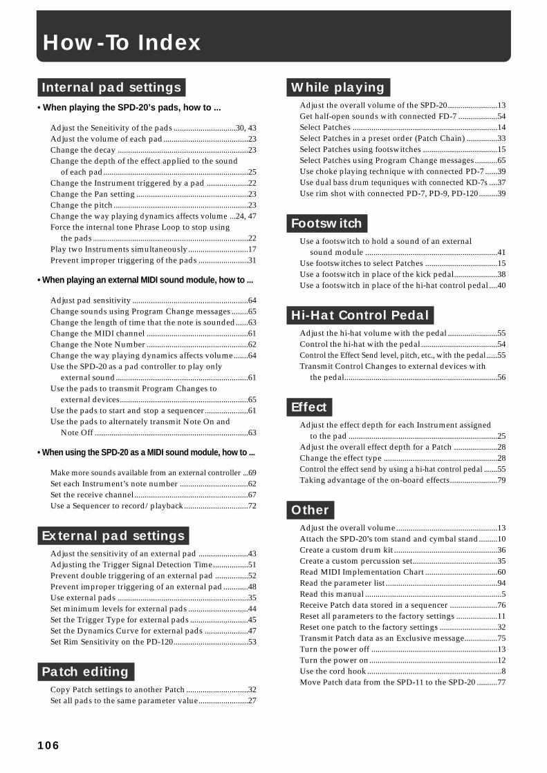
Internal pad settings• When playing the SPD-20’s pads, how to ...
Adjust the Seneitivity of the pads ..............................30, 43Adjust the volume of each pad.........................................23Change the decay ...............................................................23Change the depth of the effect applied to the sound
of each pad......................................................................25Change the Instrument triggered by a pad ....................22Change the Pan setting ......................................................23Change the pitch.................................................................23Change the way playing dynamics affects volume ...24, 47Force the internal tone Phrase Loop to stop using
the pads...........................................................................22Play two Instruments simultaneously.............................17Prevent improper triggering of the pads ........................31
• When playing an external MIDI sound module, how to ...
Adjust pad sensitivity ........................................................64Change sounds using Program Change messages ........65Change the length of time that the note is sounded......63Change the MIDI channel .................................................61Change the Note Number .................................................62Change the way playing dynamics affects volume.......64Use the SPD-20 as a pad controller to play only
external sound................................................................61Use the pads to transmit Program Changes to
external devices..............................................................65Use the pads to start and stop a sequencer.....................61Use the pads to alternately transmit Note On and
Note Off ..........................................................................63
• When using the SPD-20 as a MIDI sound module, how to ...
Make more sounds available from an external controller ...69Set each Instrument’s note number .................................62Set the receive channel.......................................................67Use a Sequencer to record/playback...............................72
External pad settingsAdjust the sensitivity of an external pad ........................43Adjusting the Trigger Signal Detection Time.................51Prevent double triggering of an external pad ................52Prevent improper triggering of an external pad............48Use external pads ...............................................................35Set minimum levels for external pads .............................44Set the Trigger Type for external pads ............................45Set the Dynamics Curve for external pads .....................47Set Rim Sensitivity on the PD-120....................................53
Patch editingCopy Patch settings to another Patch ..............................32Set all pads to the same parameter value........................27
While playingAdjust the overall volume of the SPD-20........................13Get half-open sounds with connected FD-7 ...................54Select Patches ......................................................................14Select Patches in a preset order (Patch Chain) ...............33Select Patches using footswitches ....................................15Select Patches using Program Change messages...........65Use choke playing technique with connected PD-7 ......39Use dual bass drum tequniques with connected KD-7s ....37Use rim shot with connected PD-7, PD-9, PD-120.........39
FootswitchUse a footswitch to hold a sound of an external
sound module ................................................................41Use footswitches to select Patches ...................................15Use a footswitch in place of the kick pedal.....................38Use a footswitch in place of the hi-hat control pedal ....40
Hi-Hat Control PedalAdjust the hi-hat volume with the pedal ........................55Control the hi-hat with the pedal.....................................54Control the Effect Send level, pitch, etc., with the pedal......55Transmit Control Changes to external devices with
the pedal..........................................................................56
EffectAdjust the effect depth for each Instrument assigned
to the pad ........................................................................25Adjust the overall effect depth for a Patch .....................28Change the effect type .......................................................28Control the effect send by using a hi-hat control pedal .......55Taking advantage of the on-board effects.......................79
OtherAdjust the overall volume.................................................13Attach the SPD-20’s tom stand and cymbal stand.........10Create a custom drum kit ..................................................36Create a custom percussion set.........................................35Read MIDI Implementation Chart ...................................60Read the parameter list ......................................................94Read this manual ..................................................................5Receive Patch data stored in a sequencer .......................76Reset all parameters to the factory settings ....................11Reset one patch to the factory settings ............................32Transmit Patch data as an Exclusive message................75Turn the power off .............................................................13Turn the power on..............................................................12Use the cord hook.................................................................8Move Patch data from the SPD-11 to the SPD-20 ..........77
How-To Index
106

2
Used for instructions intended to alert the user to the risk of injury or material damage should the unit be used improperly.
* Material damage refers to damage or other adverse effects caused with respect to the home and all its furnishings, as well to domestic animals or pets.
Used for instructions intended to alert the user to the risk of death or severe injury should the unit be used improperly.
The ● symbol alerts the user to things that must be carried out. The specific thing that must be done is indicated by the design contained within the circle. In the case of the symbol at left, it means that the power-cord plug must be unplugged from the outlet.
The symbol alerts the user to important instructions or warnings.The specific meaning of the symbol is determined by the design contained within the triangle. In the case of the symbol at left, it is used for general cautions, warnings, or alerts to danger.
The symbol alerts the user to items that must never be carried out (are forbidden). The specific thing that must not be done is indicated by the design contained within the circle. In the case of the symbol at left, it means that the unit must never be disassembled.
• Before using this unit, make sure to read theinstructions below, and the Owner's Manual.
.........................................................................................................
• Do not open (or modify in any way) the unit or itsAC adaptor.
.........................................................................................................
• Do not attempt to repair the unit, or replace partswithin it (except when this manual provides spe-cific instructions directing you to do so). Refer allservicing to your retailer, the nearest RolandService Center, or an authorized Roland distribu-tor, as listed on the "Information" page.
.........................................................................................................
• Never use or store the unit in places that are:• Subject to temperature extremes (e.g., direct
sunlight in an enclosed vehicle, near a heatingduct, on top of heat-generating equipment); orare
• Damp (e.g., baths, washrooms, on wet floors);or are
• Humid; or are• Dusty; or are• Subject to high levels of vibration.
.........................................................................................................
• When using the unit with a rack or stand recom-mended by Roland, the rack or stand must be care-fully placed so it is level and sure to remain stable.If not using a rack or stand, you still need to makesure that any location you choose for placing theunit provides a level surface that will properlysupport the unit, and keep it from wobbling.
.........................................................................................................
• Be sure to use only the AC adaptor supplied withthe unit. Also, make sure the line voltage at theinstallation matches the input voltage specified onthe AC adaptor's body. Other AC adaptors mayuse a different polarity, or be designed for a differ-ent voltage, so their use could result in damage,malfunction, or electric shock.
.........................................................................................................
• Avoid damaging the power cord. Do not bend itexcessively, step on it, place heavy objects on it,etc. A damaged cord can easily become a shock orfire hazard. Never use a power cord after it hasbeen damaged.
.........................................................................................................
• This unit, either alone or in combination with anamplifier and headphones or speakers, may becapable of producing sound levels that could causepermanent hearing loss. Do not operate for a longperiod of time at a high volume level, or at a levelthat is uncomfortable. If you experience any hear-ing loss or ringing in the ears, you should immedi-ately stop using the unit, and consult an audiolo-gist.
.........................................................................................................
• Do not allow any objects (e.g., flammable material,coins, pins); or liquids of any kind (water, softdrinks, etc.) to penetrate the unit.
.........................................................................................................
For the USA
FEDERAL COMMUNICATIONS COMMISSIONRADIO FREQUENCY INTERFERENCE STATEMENT
This equipment has been tested and found to comply with the limits for a Class B digital device, pursuant to Part 15 of the FCC Rules. These limits are designed to provide reasonable protection against harmful interference in a residential installation. This equipment generates, uses, and can radiate radio frequency energy and, if not installed and used in accordance with the instructions, may cause harmful interference to radio communications. However, there is no guarantee that interference will not occur in a particular installation. If this equipment does cause harmful interference to radio or television reception, which can be determined by turning the equipment off and on, the user is encouraged to try to correct the interference by one or more of the following measures:
– Reorient or relocate the receiving antenna.– Increase the separation between the equipment and receiver.– Connect the equipment into an outlet on a circuit different from that to which the receiver is connected.– Consult the dealer or an experienced radio/TV technician for help.
Unauthorized changes or modification to this system can void the users authority to operate this equipment.This equipment requires shielded interface cables in order to meet FCC class B Limit.
IMPORTANT: THE WIRES IN THIS MAINS LEAD ARE COLOURED IN ACCORDANCE WITH THE FOLLOWING CODE.
BLUE: BROWN:
As the colours of the wires in the mains lead of this apparatus may not correspond with the coloured markings identifying the terminals in your plug, proceed as follows:The wire which is coloured BLUE must be connected to the terminal which is marked with the letter N or coloured BLACK.The wire which is coloured BROWN must be connected to the terminal which is marked with the letter L or coloured RED.Under no circumstances must either of the above wires be connected to the earth terminal of a three pin plug.
NEUTRALLIVE
For the U.K.
This product complies with the requirements of European Directive 89/336/EEC.
For EU Countries
For EU Countries
Apparatus containing Lithium batteries
ADVARSEL!Lithiumbatteri - Eksplosionsfare ved fejlagtig håndtering.Udskiftning må kun ske med batteri afsamme fabrikat og type.Levér det brugte batteri tilbage til leverandøren.
VARNINGExplosionsfara vid felaktigt batteribyte.Använd samma batterityp eller en ekvivalent typ som rekommenderas av apparattillverkaren.Kassera använt batteri enligt fabrikantens instruktion.
CAUTIONDanger of explosion if battery is incorrectly replaced.Replace only with the same or equivalent type recommended by the manufacturer.Discard used batteries according to the manufacturer’s instructions.
ADVARSELEksplosjonsfare ved feilaktig skifte av batteri.Benytt samme batteritype eller en tilsvarende type anbefalt av apparatfabrikanten.Brukte batterier kasseres i henhold til fabrikantens instruks joner.
VAROITUSParisto voi räjähtää, jos se onvirheellisesti asennettu.Vaihda paristo ainoastaan laitevalmistajan suosittelemaan tyyppiin. Hävitä käytetty paristo valmistajan ohjeiden mukaisesti.
For Canada
This Class B digital apparatus meets all requirements of the Canadian Interference-Causing Equipment Regulations.
Cet appareil numérique de la classe B respecte toutes les exigences du Règlement sur le matériel brouilleur du Canada.
NOTICE
AVIS
01453923 '02-2-AE2-61N
OWNER’S MANUAL
Thank you, and congratulations on your choice of the SPD-20Total Percussion Pad. The SPD-20 is an electronic percussion unitthat has eight pads, trigger interfaces, a high-quality digital soundgenerator, and on-board digital effects.
Since the SPD-20 includes a sound generator and effects in onelightweight, compact package, you can use it anywhere, anytime.A wide variety of options (pads, pedals, drum stand, etc.) areavailable, allowing you to easily create a custom drum kit. Byadding sequencers or samplers, you can take advantage of thepossibilities of MIDI percussion.
The SPD-20 provides the flexibility and expandability that will beappreciated by every percussionist, from beginner to professional.
About the Symbols in This ManualWords or symbols enclosed in [square brackets] indicate panelbuttons or controls.For example, [LAYER] signifies the Layer button.
Items marked by are supplementary explanations.
Items headed by explain important points concerning theoperation of your SPD-20.
Items preceded by give you useful tips and informationregarding the use of the SPD-20.
MEMO
NOTE
Before using this unit, carefully read the sections enti-tled: “USING THE UNIT SAFELY” and “IMPORTANTNOTES” (Owner’s manual p. 2; p. 6). These sections pro-vide important information concerning the proper operation ofthe unit. Additionally, in order to feel assured that you havegained a good grasp of every feature provided by your newunit, Owner‘s manual should be read in its entirety. The man-ual should be saved and kept on hand as a convenient refer-ence.
Copyright 1998 ROLAND CORPORATIONAll rights reserved. No part of this publication may be reproduced in anyform without the written permission of ROLAND CORPORATION.
OW
NER
’S MA
NU
AL
InformationWhen you need repair service, call your nearest Roland Service Center or authorized Roland distributor in your country as shown below.
As of January 1, 2002 (Roland)
ARGENTINAInstrumentos Musicales S.A.Av.Santa Fe 2055 (1123) Buenos AiresARGENTINATEL: (011) 4508-2700 BRAZILRoland Brasil LtdaRua San Jose, 780 Sala BParque Industrial San JoseCotia - Sao Paulo - SP, BRAZILTEL: (011) 4615 5666
CANADA Roland Canada Music Ltd.(Head Office)5480 Parkwood Way Richmond B. C., V6V 2M4 CANADA TEL: (0604) 270 6626
Roland Canada Music Ltd.(Toronto Office)Unit 2, 109 Woodbine Downs Blvd, Etobicoke, ONM9W 6Y1 CANADA TEL: (0416) 213 9707
MEXICOCasa Veerkamp, s.a. de c.v.Av. Toluca No. 323, Col. Olivar de los Padres 01780 Mexico D.F. MEXICOTEL: 668-0480
PANAMASUPRO MUNDIAL, S.A.Boulevard Andrews, Albrook, Panama City, REP. DE PANAMATEL: 315-0101
U. S. A. Roland Corporation U.S.5100 S. Eastern AvenueLos Angeles, CA 90040-2938,U. S. A.TEL: (323) 890 3700
VENEZUELAMusicland Digital C.A.Av. Francisco de Miranda,Centro Parque de Cristal, Nivel C2 Local 20 CaracasVENEZUELATEL: (212) 285-8586
AUSTRALIA Roland Corporation Australia Pty., Ltd. 38 Campbell Avenue Dee Why West. NSW 2099 AUSTRALIA TEL: (02) 9982 8266 NEW ZEALAND Roland Corporation Ltd.32 Shaddock Street, Mount Eden, Auckland, NEW ZEALAND TEL: (09) 3098 715
HONG KONGTom Lee Music Co., Ltd. Service Division22-32 Pun Shan Street, Tsuen Wan, New Territories, HONG KONGTEL: 2415 0911
CHINABeijing Xinghai Musical Instruments Co., Ltd.6 Huangmuchang Chao Yang District, Beijing, CHINATEL: (010) 6774 7491
Shanghai Xingtong Acoustics Equipment CO.,Ltd.5F. No.1500 Pingliang Road New East Club Plaza, Shanghai, CHINATEL: (021) 5580-0800
INDIARivera Digitec (India) Pvt. Ltd.409, Nirman Kendra Mahalaxmi Flats Compound Off. Dr. Edwin Moses Road, Mumbai-400011, INDIATEL: (022) 498 3079 INDONESIAPT Citra IntiRamaJ1. Cideng Timur No. 15J-150 Jakarta PusatINDONESIATEL: (021) 6324170
MALAYSIABENTLEY MUSIC SDN BHD140 & 142, Jalan Bukit Bintang 55100 Kuala Lumpur,MALAYSIATEL: (03) 2144-3333
PHILIPPINESG.A. Yupangco & Co. Inc.339 Gil J. Puyat AvenueMakati, Metro Manila 1200,PHILIPPINESTEL: (02) 899 9801
SINGAPORESwee Lee Company150 Sims Drive,SINGAPORE 387381TEL: 846-3676
TAIWANROLAND TAIWAN ENTERPRISE CO., LTD.Room 5, 9fl. No. 112 Chung Shan N.Road Sec.2, Taipei, TAIWAN, R.O.C.TEL: (02) 2561 3339 THAILANDTheera Music Co. , Ltd.330 Verng NakornKasem, Soi 2, Bangkok 10100, THAILANDTEL: (02) 2248821
BAHRAINMoon StoresNo.16, Bab Al Bahrain Avenue, P.O.Box 247, Manama 304, State of BAHRAINTEL: 211 005
VIETNAMSaigon Music138 Tran Quang Khai St., District 1Ho Chi Minh CityVIETNAMTEL: (08) 844-4068
JORDANAMMAN Trading Agency 245 Prince Mohammad St., Amman 1118, JORDANTEL: (06) 464-1200
KUWAITEasa Husain Al-YousifiAbdullah Salem Street,Safat, KUWAITTEL: 243-6399 LEBANONA. Chahine & FilsGerge Zeidan St., Chahine Bldg., Achrafieh, P.O.Box: 16-5857Beirut, LEBANONTEL: (01) 20-1441
QATARAl Emadi Co. (Badie Studio & Stores)P.O. Box 62, Doha, QATARTEL: 4423-554 SAUDI ARABIAaDawliah Universal Electronics APLCorniche Road, Aldossary Bldg., 1st Floor, Alkhobar,SAUDI ARABIA
P.O.Box 2154, Alkhobar 31952SAUDI ARABIA TEL: (03) 898 2081 SYRIATechnical Light & Sound CenterBldg. No. 47, Khaled Ebn Al Walid St.Damascus, SYRIATEL: (011) 221-1230
TURKEY Barkat muzik aletleri ithalat ve ihracat Ltd StiSiraselviler Caddesi Siraselviler Pasaji No:74/20 Taksim - Istanbul, TURKEYTEL: (0212) 2499324 U.A.E.Zak Electronics & Musical Instruments Co. L.L.C.Zabeel Road, Al Sherooq Bldg., No. 14, Grand Floor, Dubai, U.A.E.TEL: (04) 3360715
EGYPTAl Fanny Trading Office9, EBN Hagar A1 Askalany Street,ARD E1 Golf, Heliopolis, Cairo 11341, EGYPTTEL: 20-2-417-1828 REUNIONMaison FO - YAM Marcel25 Rue Jules Hermann,Chaudron - BP79 97 491Ste Clotilde Cedex,REUNION ISLANDTEL: (0262) 218-429
SOUTH AFRICAThat Other Music Shop (PTY) Ltd.11 Melle St., Braamfontein, Johannesbourg, SOUTH AFRICA
P.O.Box 32918, Braamfontein 2017 Johannesbourg, SOUTH AFRICATEL: (011) 403 4105
Paul Bothner (PTY) Ltd.17 Werdmuller Centre, Main Road, Claremont 7708SOUTH AFRICA
P.O.BOX 23032, Claremont 7735, SOUTH AFRICATEL: (021) 674 4030
CYPRUSRadex Sound Equipment Ltd.17, Diagorou Street, Nicosia, CYPRUSTEL: (02) 66-9426
DENMARK Roland Scandinavia A/SNordhavnsvej 7, Postbox 880,DK-2100 CopenhagenDENMARK TEL: (039)16 6200 FRANCERoland France SA4, Rue Paul Henri SPAAK, Parc de l'Esplanade, F 77 462 St. Thibault, Lagny Cedex FRANCETEL: 01 600 73 500 FINLANDRoland Scandinavia As, Filial FinlandLauttasaarentie 54 BFin-00201 Helsinki, FINLANDTEL: (9) 682 4020 GERMANY Roland Elektronische Musikinstrumente HmbH.Oststrasse 96, 22844 Norderstedt, GERMANY TEL: (040) 52 60090
GREECESTOLLAS S.A.Music Sound Light155, New National RoadPatras 26442, GREECETEL: (061) 43-5400 HUNGARYIntermusica Ltd.Warehouse Area ‘DEPO’ Pf.83H-2046 Torokbalint, HUNGARYTEL: (23) 511011 IRELANDRoland IrelandAudio House, Belmont Court,Donnybrook, Dublin 4.Republic of IRELANDTEL: (01) 2603501
ITALYRoland Italy S. p. A. Viale delle Industrie 8, 20020 Arese, Milano, ITALYTEL: (02) 937-78300 NORWAYRoland Scandinavia Avd. Kontor NorgeLilleakerveien 2 Postboks 95 Lilleaker N-0216 Oslo NORWAYTEL: 273 0074 POLANDP. P. H. BrzostowiczUL. Gibraltarska 4.PL-03664 Warszawa POLANDTEL: (022) 679 44 19 PORTUGALTecnologias Musica e Audio, Roland Portugal, S.A.Cais Das Pedras, 8/9-1 Dto4050-465 PORTOPORTUGALTEL: (022) 608 00 60
RUSSIAMuTek3-Bogatyrskaya Str. 1.k.l107 564 Moscow, RUSSIA TEL: (095) 169 5043
SPAINRoland Electronics de España, S. A. Calle Bolivia 239, 08020 Barcelona, SPAINTEL: (93) 308 1000
SWITZERLANDRoland (Switzerland) AGMusitronic AG Gerberstrasse 5, Postfach,CH-4410 Liestal, SWITZERLANDTEL: (061) 927-8383
SWEDEN Roland Scandinavia A/S SWEDISH SALES OFFICEDanvik Center 28, 2 tr. S-131 30 Nacka SWEDEN TEL: (08) 702 0020
UKRAINETIC-TACMira Str. 19/108P.O. Box 180 295400 Munkachevo, UKRAINETEL: (03131) 414-40 UNITED KINGDOM Roland (U.K.) Ltd.Atlantic Close, Swansea Enterprise Park, SWANSEASA7 9FJ, UNITED KINGDOMTEL: (01792) 700139
KOREACosmos Corporation1461-9, Seocho-Dong,Seocho Ku, Seoul, KOREATEL: (02) 3486-8855
AUSTRIARoland Austria GES.M.B.H.Siemensstrasse 4, P.O. Box 74,A-6063 RUM, AUSTRIATEL: (0512) 26 44 260 BELGIUM/HOLLAND/LUXEMBOURGRoland Benelux N. V.Houtstraat 3, B-2260, Oevel (Westerlo) BELGIUMTEL: (014) 575811
AFRICA
CHILEComercial Fancy S.A.Rut.: 96.919.420-1Nataniel Cox #739, 4th FloorSantiago - Centro, CHILETEL: (02) 688-9540
URUGUAYTodo Musica S.A.Francisco Acuna de Figueroa 1771C.P.: 11.800 Montevideo, URUGUAYTEL: (02) 924-2335
EUROPEAUSTRALIA/NEW ZEALAND
ASIA
CENTRAL/LATINAMERICA
NORTH AMERICA
MIDDLE EAST
AFRICA
EL SALVADOROMNI MUSIC75 Avenida Norte y Final Alameda Juan Pablo , Edificio No.4010 San Salvador, EL SALVADORTEL: 262-0788
ROMANIAFBS LINESPiata Libertatii 1,RO-4200 GheorghehiTEL: (095) 169-5043
PARAGUAYDistribuidora De Instrumentos MusicalesJ.E. Olear y ESQ. Manduvira Asuncion PARAGUAYTEL: (021) 492-124 PERUVIDEO Broadcast S.A.Portinari 199 (ESQ. HALS), San Borja, Lima 41,REP. OF PERUTEL: (01) 4758226
COSTA RICAJUAN Bansbach Instrumentos MusicalesAve.1. Calle 11, Apartado 10237,San Jose, COSTA RICATEL: 258-0211
CRISTOFORI MUSIC PTE LTDBlk 3014, Bedok Industrial Park E, #02-2148, SINGAPORE 489980TEL: 243 9555
IRANMOCO, INC.No.41 Nike St., Dr.Shariyati Ave.,Roberoye Cerahe MirdamadTehran, IRANTEL: (021) 285-4169
ISRAELHalilit P. Greenspoon & Sons Ltd.8 Retzif Ha'aliya Hashnya St.Tel-Aviv-Yafo ISRAELTEL: (03) 6823666