wifi onu user manual - gpon epon olt onu ftth pon eoc...
TRANSCRIPT
WIFI ONU User Manual
WIFI ONU User Manual
WIFI ONU User Manual
Contents
Contents ............................................................................................................................ 2
1. Hardware Setup ............................................................................................................ 3
1.1 Unpack Your ONU ................................................................................................ 3
1.2 Hardware Features .............................................................................................. 4
1.3Position Your ONU ................................................................................................ 5
1.4 Connect Your ONU .............................................................................................. 6
2 Getting Start ................................................................................................................... 7
2.1 Prepare for login the ONU Wi-Fi web management ............................................. 7
2.2 Login the Web Management Interface ................................................................. 7
3 Know WEB Management Interface ................................................................................ 8
3.1 WEB Management Interface Introduction ............................................................ 8
3.2 Main Menu Introduction ....................................................................................... 9
4 Running .......................................................................................................................... 9
4.1 Device information ............................................................................................... 9
4.2 Network Status ................................................................................................... 10
4.3 Wireless Status .................................................................................................. 10
4.4 Configuration Wizard ......................................................................................... 11
5 Network ........................................................................................................................ 11
5.1 WAN Setting ...................................................................................................... 11
5.1.1 WAN Connection Named Rule ................................................................. 11
5.1.2 Default WAN Connection and Router Mode............................................. 12
5.1.3 Add An Bridge Mode WAN Connection .................................................... 14
5.2 LAN Setting ........................................................................................................ 15
6 Wireless ....................................................................................................................... 17
6.1 Base Setting ....................................................................................................... 17
6.2 MAC Filter .......................................................................................................... 18
7 Security ........................................................................................................................ 19
7.1 Basic setting ....................................................................................................... 19
7.2 URL Filter ........................................................................................................... 19
7.3 IP Filter ............................................................................................................... 20
8 System ......................................................................................................................... 20
8.1 Management ...................................................................................................... 20
8.2 System Upgrade ................................................................................................ 21
8.3 Device Reboot ................................................................................................... 23
8.4 Restore Factory ................................................................................................. 24
8.5 System Log ........................................................................................................ 24
WIFI ONU User Manual
1. Hardware Setup
Getting to know your ONU
The WiFi ONU provides you with an easy and secure way to set up a wireless home
network with fast access to the Internet over a optical fiber network.
This chapter explains how to set up your hardware. If you have already set up your WIFI
ONU, you can skip this chapter. Chapter 2 explains how to set up.
This chapter contains the following sections:
Unpack Your ONU
Hardware Features
Position Your ONU
Connect Your ONU
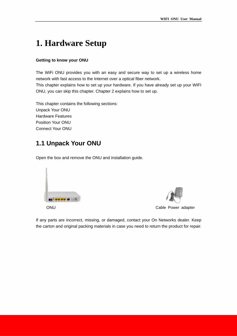
1.1 Unpack Your ONU
Open the box and remove the ONU and installation guide.
ONU Cable Power adapter
If any parts are incorrect, missing, or damaged, contact your On Networks dealer. Keep
the carton and original packing materials in case you need to return the product for repair.
WIFI ONU User Manual
1.2 Hardware Features
Before you install the ONU, take a moment to become familiar with the front, side, and
back panels and the label. Pay particular attention to the LEDs on the front panel.
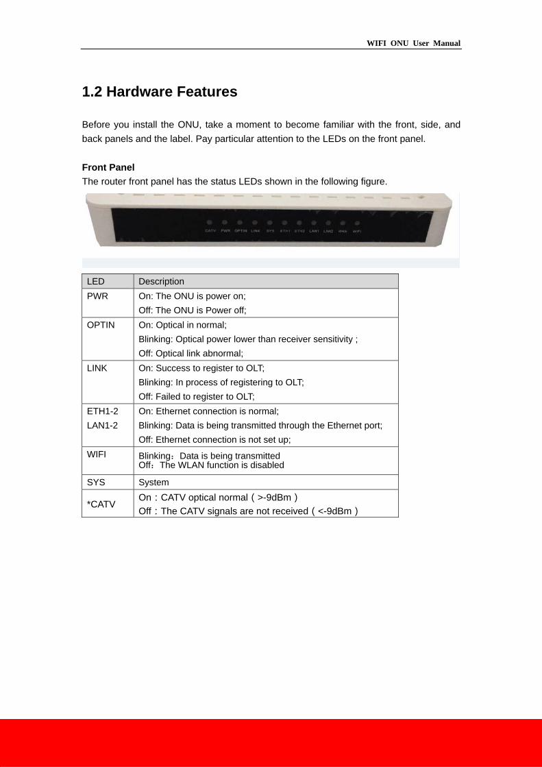
Front Panel
The router front panel has the status LEDs shown in the following figure.
LED Description
PWR On: The ONU is power on;
Off: The ONU is Power off;
OPTIN On: Optical in normal;
Blinking: Optical power lower than receiver sensitivity ;
Off: Optical link abnormal;
LINK On: Success to register to OLT;
Blinking: In process of registering to OLT;
Off: Failed to register to OLT;
ETH1-2
LAN1-2
On: Ethernet connection is normal;
Blinking: Data is being transmitted through the Ethernet port;
Off: Ethernet connection is not set up;
WIFI Blinking:Data is being transmitted Off:The WLAN function is disabled
SYS System
*CATV On:CATV optical normal(>-9dBm)
Off:The CATV signals are not received(<-9dBm)
WIFI ONU User Manual
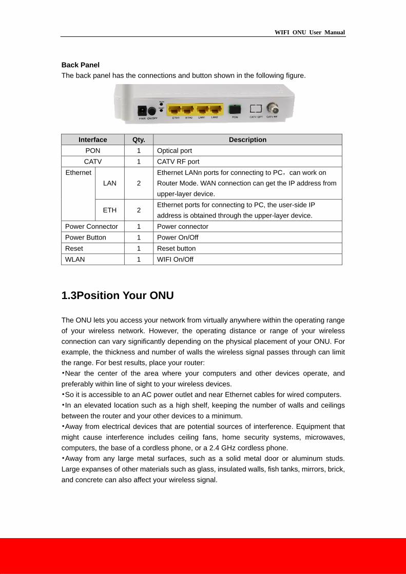
Back Panel
The back panel has the connections and button shown in the following figure.
Interface Qty. Description
PON 1 Optical port
CATV 1 CATV RF port
Ethernet
LAN 2
Ethernet LANn ports for connecting to PC,can work on
Router Mode. WAN connection can get the IP address from
upper-layer device.
ETH 2 Ethernet ports for connecting to PC, the user-side IP
address is obtained through the upper-layer device.
Power Connector 1 Power connector
Power Button 1 Power On/Off
Reset 1 Reset button
WLAN 1 WIFI On/Off
1.3Position Your ONU
The ONU lets you access your network from virtually anywhere within the operating range
of your wireless network. However, the operating distance or range of your wireless
connection can vary significantly depending on the physical placement of your ONU. For
example, the thickness and number of walls the wireless signal passes through can limit
the range. For best results, place your router:
•Near the center of the area where your computers and other devices operate, and
preferably within line of sight to your wireless devices.
•So it is accessible to an AC power outlet and near Ethernet cables for wired computers.
•In an elevated location such as a high shelf, keeping the number of walls and ceilings
between the router and your other devices to a minimum.
•Away from electrical devices that are potential sources of interference. Equipment that
might cause interference includes ceiling fans, home security systems, microwaves,
computers, the base of a cordless phone, or a 2.4 GHz cordless phone.
•Away from any large metal surfaces, such as a solid metal door or aluminum studs.
Large expanses of other materials such as glass, insulated walls, fish tanks, mirrors, brick,
and concrete can also affect your wireless signal.
WIFI ONU User Manual
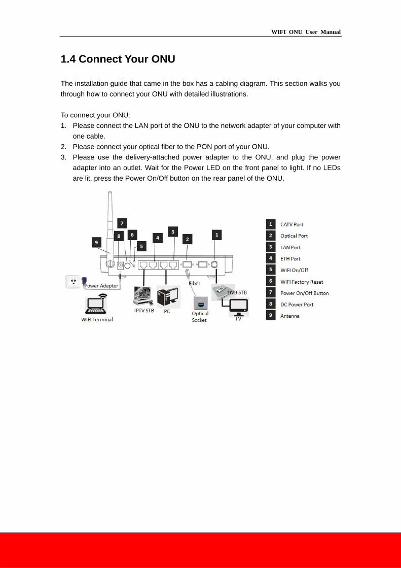
1.4 Connect Your ONU
The installation guide that came in the box has a cabling diagram. This section walks you
through how to connect your ONU with detailed illustrations.
To connect your ONU:
1. Please connect the LAN port of the ONU to the network adapter of your computer with
one cable.
2. Please connect your optical fiber to the PON port of your ONU.
3. Please use the delivery-attached power adapter to the ONU, and plug the power
adapter into an outlet. Wait for the Power LED on the front panel to light. If no LEDs
are lit, press the Power On/Off button on the rear panel of the ONU.
WIFI ONU User Manual
2 Getting Start
2.1 Prepare for login the ONU Wi-Fi web management
Before you login the ONU, you should confirm the connect between the CPE and your
PC is normal.
Step 1 Configuring the IP address of your PC to 192.168.1.X(2~254), subnet mask
is 255.255.255.0,gateway is 192.168.1.1.
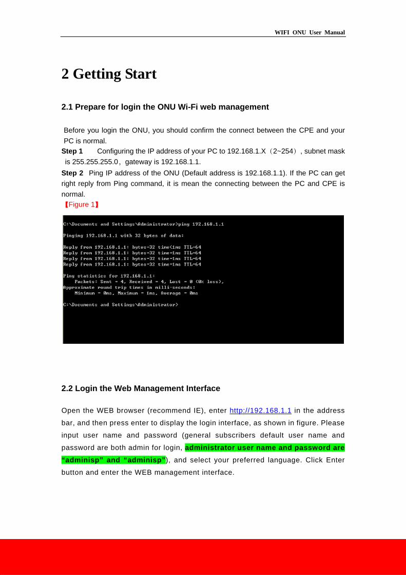
Step 2 Ping IP address of the ONU (Default address is 192.168.1.1). If the PC can get
right reply from Ping command, it is mean the connecting between the PC and CPE is
normal.
【Figure 1】
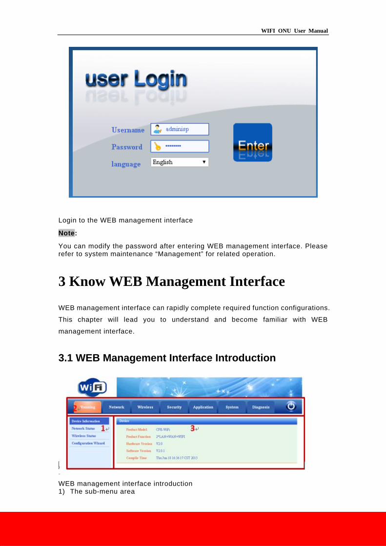
2.2 Login the Web Management Interface
Open the WEB browser (recommend IE), enter http://192.168.1.1 in the address
bar, and then press enter to display the login interface, as shown in figure. Please
input user name and password (general subscribers default user name and
password are both admin for login, administrator user name and password are
“adminisp” and “adminisp”), and select your preferred language. Click Enter
button and enter the WEB management interface.
WIFI ONU User Manual
Login to the WEB management interface
Note:
You can modify the password after entering WEB management interface. Please refer to system maintenance “Management” for related operation.
3 Know WEB Management Interface
WEB management interface can rapidly complete required function configurations.
This chapter will lead you to understand and become familiar with WEB
management interface.
3.1 WEB Management Interface Introduction
WEB management interface introduction 1) The sub-menu area
WIFI ONU User Manual
2) The main menu area 3) Display the content
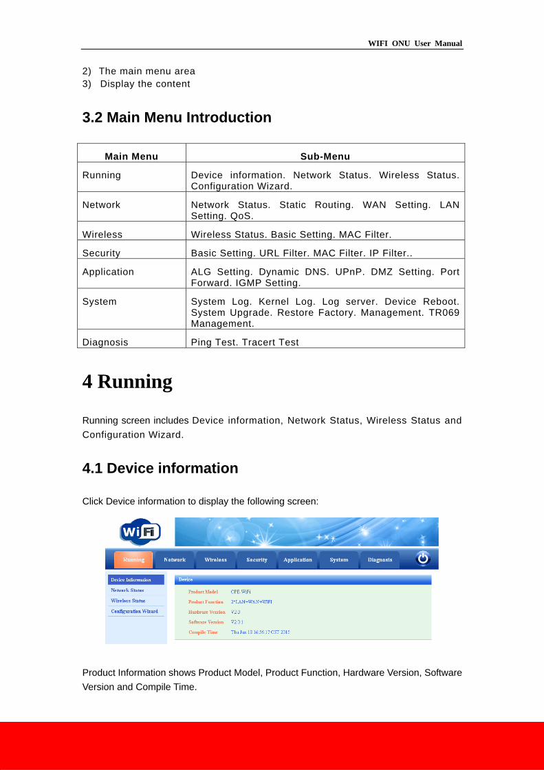
3.2 Main Menu Introduction
Main Menu Sub-Menu
Running Device information. Network Status. Wireless Status. Configuration Wizard.
Network Network Status. Static Routing. WAN Setting. LAN Setting. QoS.
Wireless Wireless Status. Basic Setting. MAC Filter.
Security Basic Setting. URL Filter. MAC Filter. IP Filter..
Application ALG Setting. Dynamic DNS. UPnP. DMZ Setting. Port Forward. IGMP Setting.
System System Log. Kernel Log. Log server. Device Reboot. System Upgrade. Restore Factory. Management. TR069 Management.
Diagnosis Ping Test. Tracert Test
4 Running
Running screen includes Device information, Network Status, Wireless Status and
Configuration Wizard.
4.1 Device information
Click Device information to display the following screen:
Product Information shows Product Model, Product Function, Hardware Version, Software
Version and Compile Time.
WIFI ONU User Manual
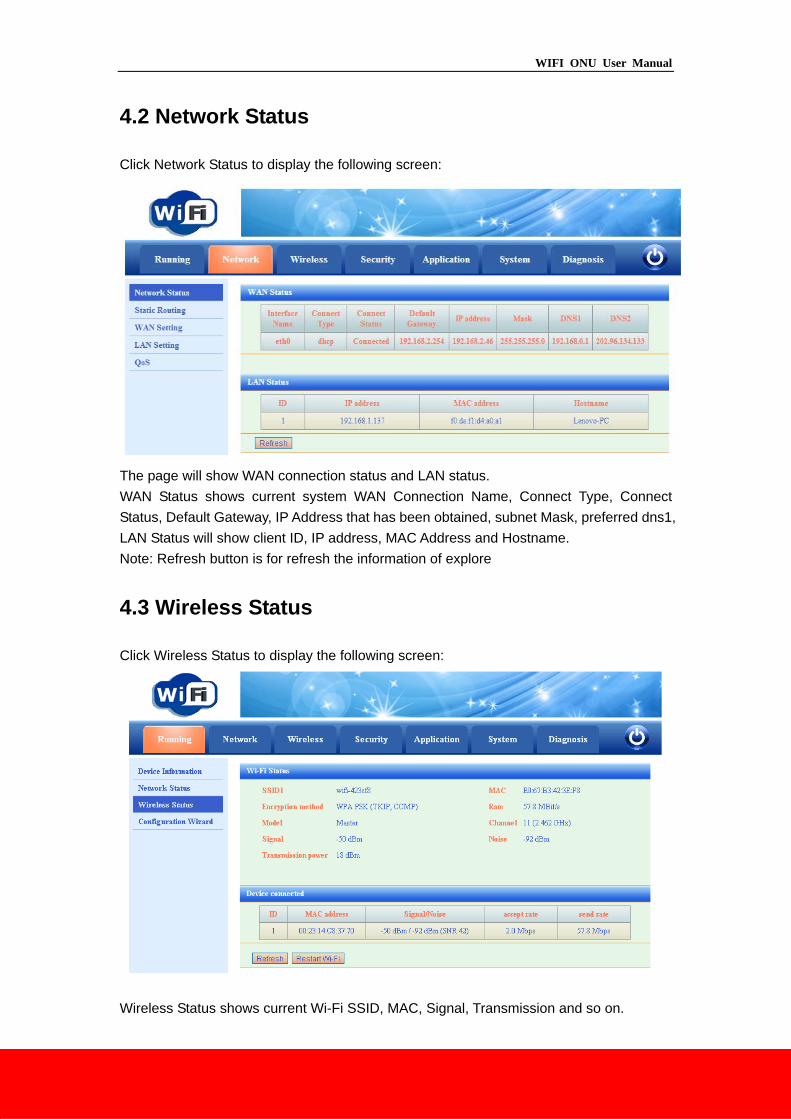
4.2 Network Status
Click Network Status to display the following screen:
The page will show WAN connection status and LAN status.
WAN Status shows current system WAN Connection Name, Connect Type, Connect
Status, Default Gateway, IP Address that has been obtained, subnet Mask, preferred dns1,
LAN Status will show client ID, IP address, MAC Address and Hostname.
Note: Refresh button is for refresh the information of explore
4.3 Wireless Status
Click Wireless Status to display the following screen:
Wireless Status shows current Wi-Fi SSID, MAC, Signal, Transmission and so on.
WIFI ONU User Manual
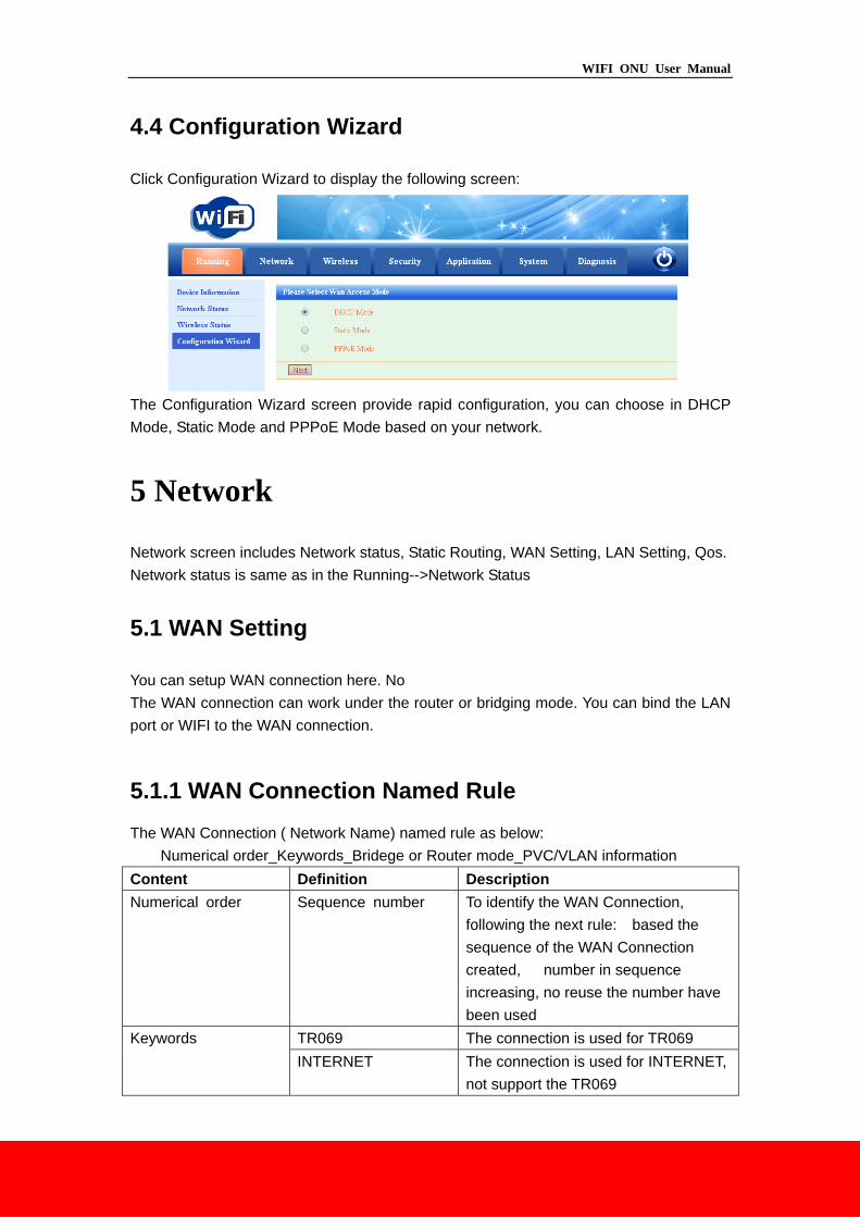
4.4 Configuration Wizard
Click Configuration Wizard to display the following screen:
The Configuration Wizard screen provide rapid configuration, you can choose in DHCP
Mode, Static Mode and PPPoE Mode based on your network.
5 Network
Network screen includes Network status, Static Routing, WAN Setting, LAN Setting, Qos.
Network status is same as in the Running-->Network Status
5.1 WAN Setting
You can setup WAN connection here. No
The WAN connection can work under the router or bridging mode. You can bind the LAN
port or WIFI to the WAN connection.
5.1.1 WAN Connection Named Rule
The WAN Connection ( Network Name) named rule as below:
Numerical order_Keywords_Bridege or Router mode_PVC/VLAN information
Content Definition Description
Numerical order Sequence number To identify the WAN Connection,
following the next rule: based the
sequence of the WAN Connection
created, number in sequence
increasing, no reuse the number have
been used
Keywords TR069 The connection is used for TR069
INTERNET The connection is used for INTERNET,
not support the TR069
WIFI ONU User Manual
TR069_INTERNET The connection is used for INTERNET
and the TR069
Bridge or Router B Bridge Mode
R Router Mode
VLAN VID_Z Z of VID_Z is the VLAN_ID value (for
untag
WAN Connection, value of Z is Null
and do not appear in the connection’s
name)
For Example:
1_INTERNET_R_VID_2 (The WAN Connection is used for INTERNET, working mode is
Router, VLAN ID is 2)
2_INTERNET_B_VID_ (The WAN Connection is used for INTERNET, working mode is
Bridge, VLAN ID is Null)
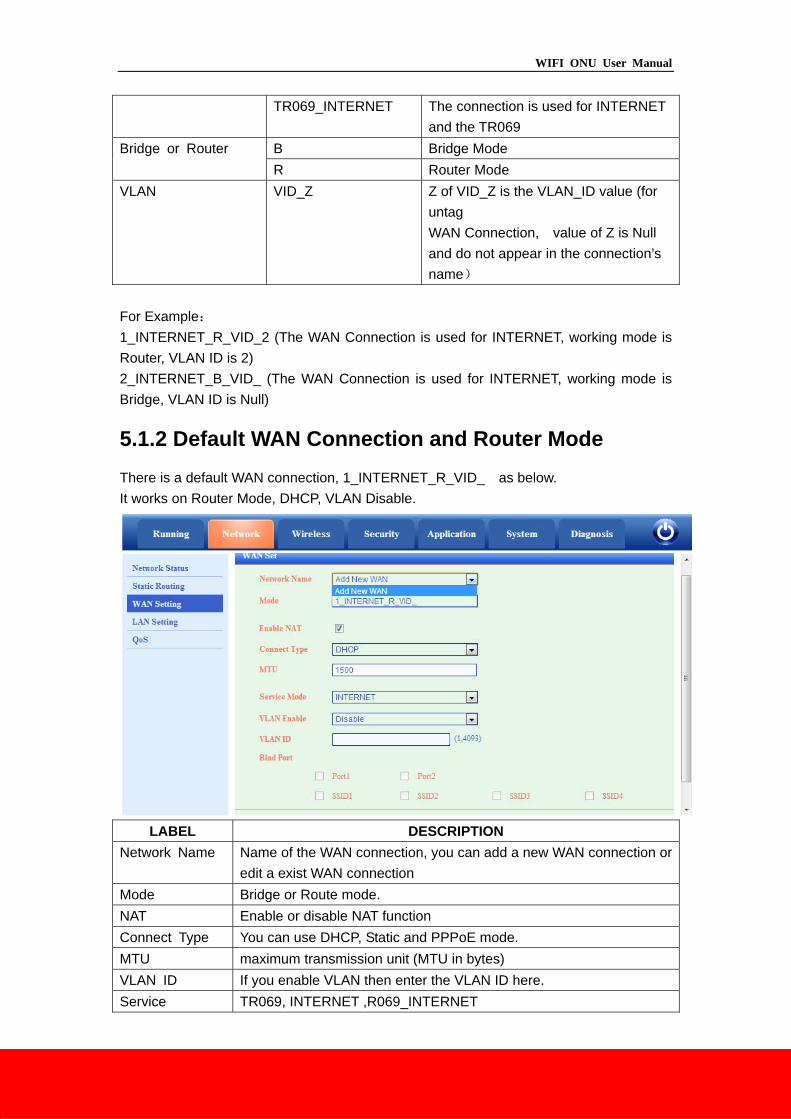
5.1.2 Default WAN Connection and Router Mode
There is a default WAN connection, 1_INTERNET_R_VID_ as below.
It works on Router Mode, DHCP, VLAN Disable.
LABEL DESCRIPTION
Network Name Name of the WAN connection, you can add a new WAN connection or
edit a exist WAN connection
Mode Bridge or Route mode.
NAT Enable or disable NAT function
Connect Type You can use DHCP, Static and PPPoE mode.
MTU maximum transmission unit (MTU in bytes)
VLAN ID If you enable VLAN then enter the VLAN ID here.
Service TR069, INTERNET ,R069_INTERNET
WIFI ONU User Manual
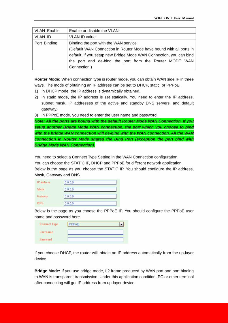
VLAN Enable Enable or disable the VLAN
VLAN ID VLAN ID value
Port Binding Binding the port with the WAN service
(Default WAN Connection in Router Mode have bound with all ports in
default. If you setup new Bridge Mode WAN Connection, you can bind
the port and de-bind the port from the Router MODE WAN
Connection.)
Router Mode: When connection type is router mode, you can obtain WAN side IP in three
ways. The mode of obtaining an IP address can be set to DHCP, static, or PPPoE.
1) In DHCP mode, the IP address is dynamically obtained.
2) In static mode, the IP address is set statically. You need to enter the IP address,
subnet mask, IP addresses of the active and standby DNS servers, and default
gateway.
3) In PPPoE mode, you need to enter the user name and password.
Note: All the ports are bound with the default Router Mode WAN Connection. If you
setup another Bridge Mode WAN connection, the port which you choose to bind
with the bridge WAN connection will de-bind with the WAN connection. All the WAN
connection in Router Mode shared the Bind Port (exception the port bind with
Bridge Mode WAN Connection).
You need to select a Connect Type Setting in the WAN Connection configuration.
You can choose the STATIC IP, DHCP and PPPoE for different network application.
Below is the page as you choose the STATIC IP. You should configure the IP address,
Mask, Gateway and DNS.
Below is the page as you choose the PPPoE IP. You should configure the PPPoE user
name and password here.
If you choose DHCP, the router willl obtain an IP address automatically from the up-layer
device.
Bridge Mode: If you use bridge mode, L2 frame produced by WAN port and port binding
to WAN is transparent transmission. Under this application condition, PC or other terminal
after connecting will get IP address from up-layer device.
WIFI ONU User Manual
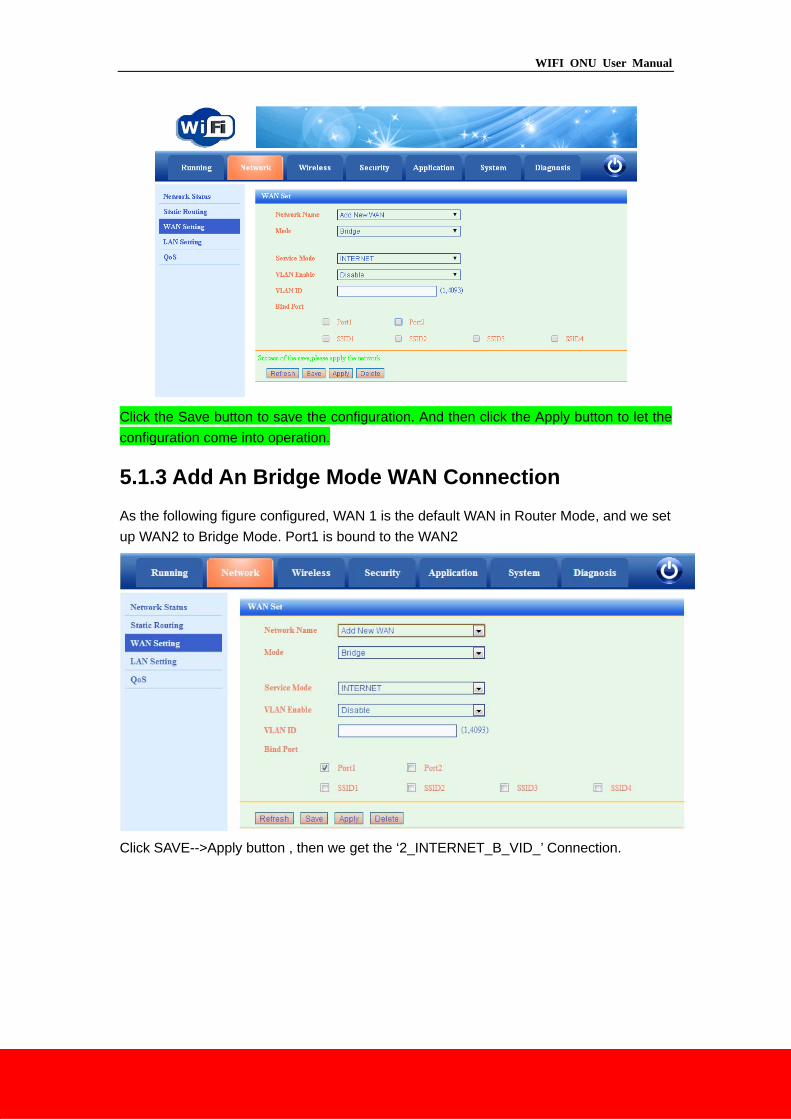
Click the Save button to save the configuration. And then click the Apply button to let the
configuration come into operation.
5.1.3 Add An Bridge Mode WAN Connection
As the following figure configured, WAN 1 is the default WAN in Router Mode, and we set
up WAN2 to Bridge Mode. Port1 is bound to the WAN2
Click SAVE-->Apply button , then we get the ‘2_INTERNET_B_VID_’ Connection.
WIFI ONU User Manual
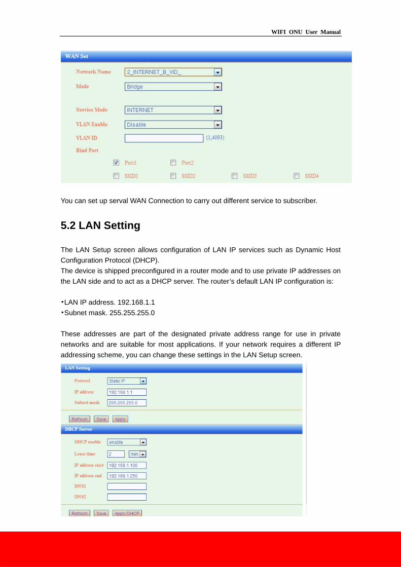
You can set up serval WAN Connection to carry out different service to subscriber.
5.2 LAN Setting
The LAN Setup screen allows configuration of LAN IP services such as Dynamic Host
Configuration Protocol (DHCP).
The device is shipped preconfigured in a router mode and to use private IP addresses on
the LAN side and to act as a DHCP server. The router’s default LAN IP configuration is:
•LAN IP address. 192.168.1.1
•Subnet mask. 255.255.255.0
These addresses are part of the designated private address range for use in private
networks and are suitable for most applications. If your network requires a different IP
addressing scheme, you can change these settings in the LAN Setup screen.
WIFI ONU User Manual
Note:If you change the LAN IP address of the router while connected through the browser,
you are disconnected. You will have to open a new connection to the new IP address and
log in again.
By default, the device acts as a DHCP server. It assigns IP, DNS server, and default
gateway addresses to all computers connected to the LAN. The assigned default IP
address of the device 192.168.1.1 is also the gateway address. The device assigns IP
addresses to the attached computers from a pool of addresses specified in the LAN Setup
screen
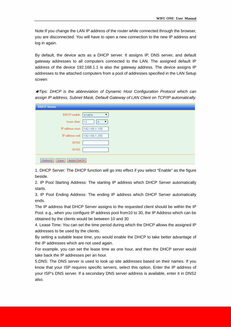
★Tips: DHCP is the abbreviation of Dynamic Host Configuration Protocol which can
assign IP address, Subnet Mask, Default Gateway of LAN Client on TCP/IP automatically.
1. DHCP Server: The DHCP function will go into effect if you select “Enable” as the figure
beside.
2. IP Pool Starting Address: The starting IP address which DHCP Server automatically
starts.
3. IP Pool Ending Address: The ending IP address which DHCP Server automatically
ends.
The IP address that DHCP Server assigns to the requested client should be within the IP
Pool. e.g., when you configure IP address pool from10 to 30, the IP Address which can be
obtained by the clients would be between 10 and 30
4. Lease Time: You can set the time period during which the DHCP allows the assigned IP
addresses to be used by the clients.
By setting a suitable lease time, you would enable the DHCP to take better advantage of
the IP addresses which are not used again.
For example, you can set the lease time as one hour, and then the DHCP server would
take back the IP addresses per an hour.
5.DNS: The DNS server is used to look up site addresses based on their names. If you
know that your ISP requires specific servers, select this option. Enter the IP address of
your ISP’s DNS server. If a secondary DNS server address is available, enter it in DNS2
also.
WIFI ONU User Manual
6 Wireless
The Wireless Settings screen lets you view or configure the wireless network setup.
There are Wireless Status, Basic Setting and MAC Filter su-menu.
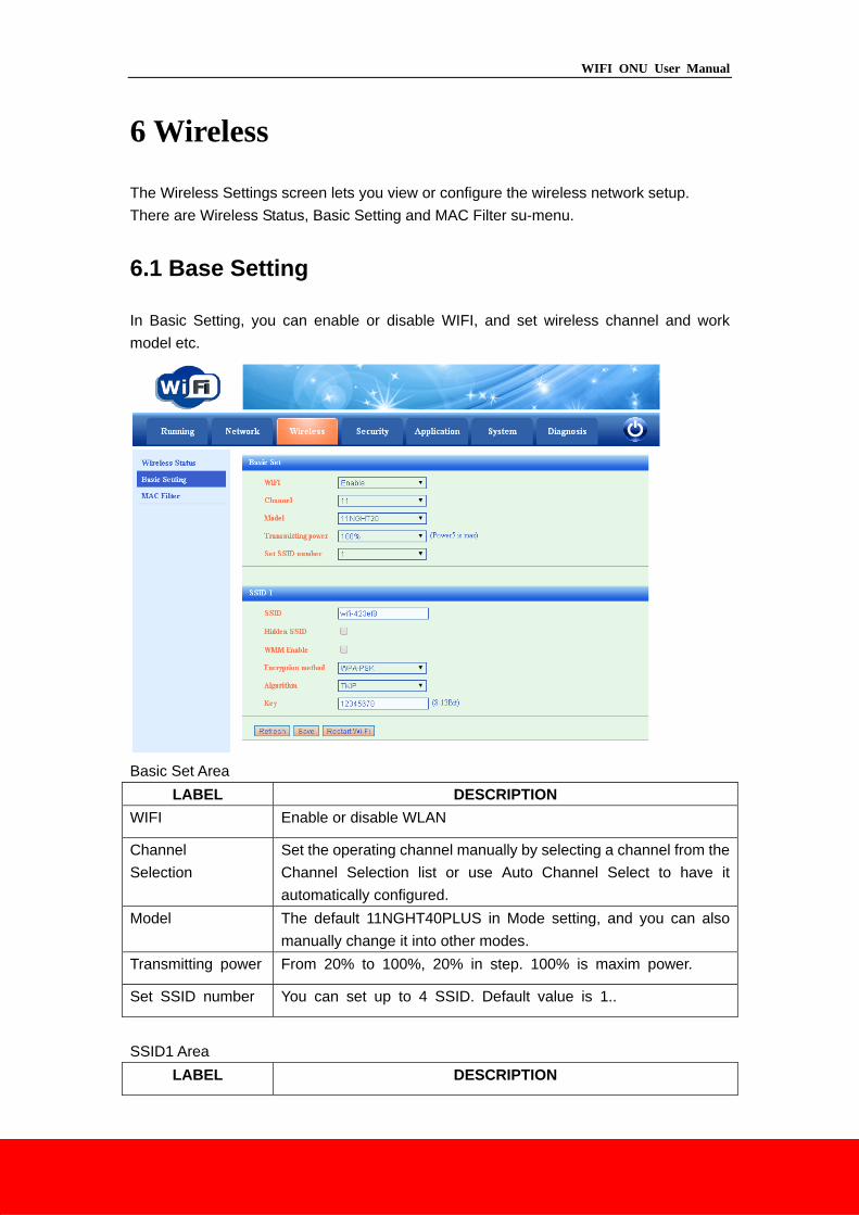
6.1 Base Setting
In Basic Setting, you can enable or disable WIFI, and set wireless channel and work
model etc.
Basic Set Area
LABEL DESCRIPTION
WIFI Enable or disable WLAN
Channel
Selection
Set the operating channel manually by selecting a channel from the
Channel Selection list or use Auto Channel Select to have it
automatically configured.
Model The default 11NGHT40PLUS in Mode setting, and you can also
manually change it into other modes.
Transmitting power From 20% to 100%, 20% in step. 100% is maxim power.
Set SSID number You can set up to 4 SSID. Default value is 1..
SSID1 Area
LABEL DESCRIPTION
WIFI ONU User Manual
SSID The SSID (Service Set IDentity) identifies the service set with
which a wireless service is associated.
Hide SSID Select this check box to hide the SSID in the outgoing beacon
frame so a station cannot obtain the SSID through scanning using
a site survey tool.
WMM Enable Select this check box to enable the WMM protocol support
Encryption method Select the authentication from None, WEP, WPA-PSK, WPA2
–PSK and Mixed WPA2/WPA –PSK. If you choose one encryption
method, you need configure the authentication method and KEY.
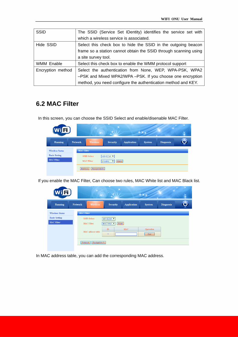
6.2 MAC Filter
In this screen, you can choose the SSID Select and enable/disenable MAC Filter.
If you enable the MAC Filter, Can choose two rules, MAC White list and MAC Black list.
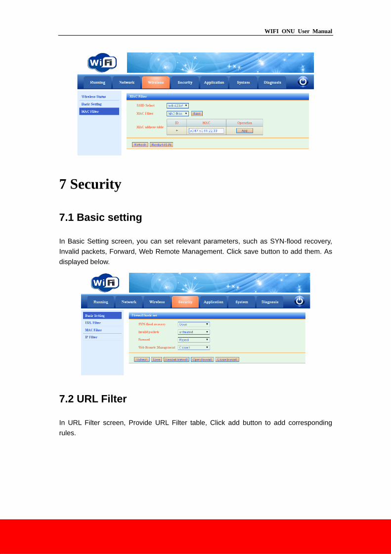
In MAC address table, you can add the corresponding MAC address.
WIFI ONU User Manual
7 Security
7.1 Basic setting
In Basic Setting screen, you can set relevant parameters, such as SYN-flood recovery,
Invalid packets, Forward, Web Remote Management. Click save button to add them. As
displayed below.
7.2 URL Filter
In URL Filter screen, Provide URL Filter table, Click add button to add corresponding
rules.
WIFI ONU User Manual
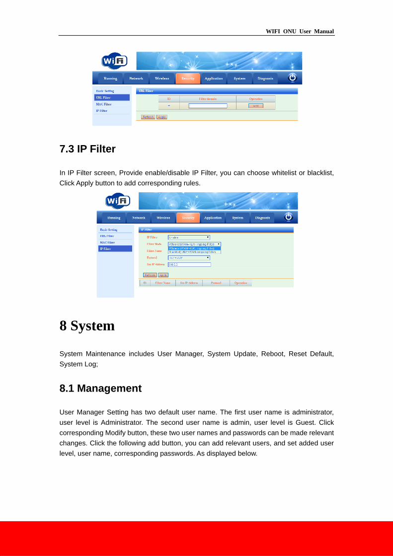
7.3 IP Filter
In IP Filter screen, Provide enable/disable IP Filter, you can choose whitelist or blacklist,
Click Apply button to add corresponding rules.
8 System
System Maintenance includes User Manager, System Update, Reboot, Reset Default,
System Log;
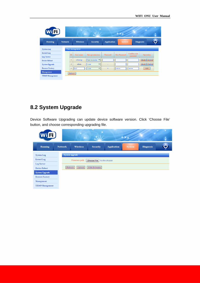
8.1 Management
User Manager Setting has two default user name. The first user name is administrator,
user level is Administrator. The second user name is admin, user level is Guest. Click
corresponding Modify button, these two user names and passwords can be made relevant
changes. Click the following add button, you can add relevant users, and set added user
level, user name, corresponding passwords. As displayed below.
WIFI ONU User Manual
8.2 System Upgrade
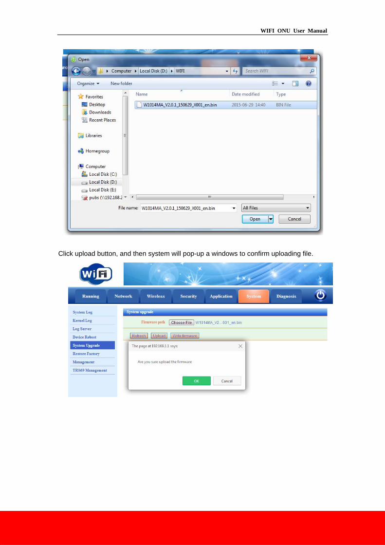
Device Software Upgrading can update device software version. Click ‘Choose File’
button, and choose corresponding upgrading file.
WIFI ONU User Manual
Click upload button, and then system will pop-up a windows to confirm uploading file.
WIFI ONU User Manual
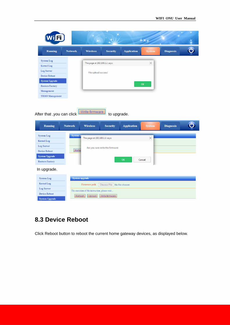
After that ,you can click to upgrade.
In upgrade.
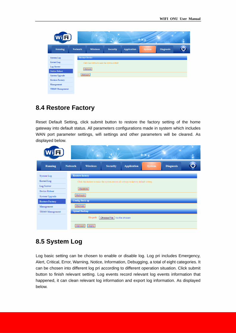
8.3 Device Reboot
Click Reboot button to reboot the current home gateway devices, as displayed below.
WIFI ONU User Manual
8.4 Restore Factory
Reset Default Setting, click submit button to restore the factory setting of the home
gateway into default status. All parameters configurations made in system which includes
WAN port parameter settings, wifi settings and other parameters will be cleared. As
displayed below.
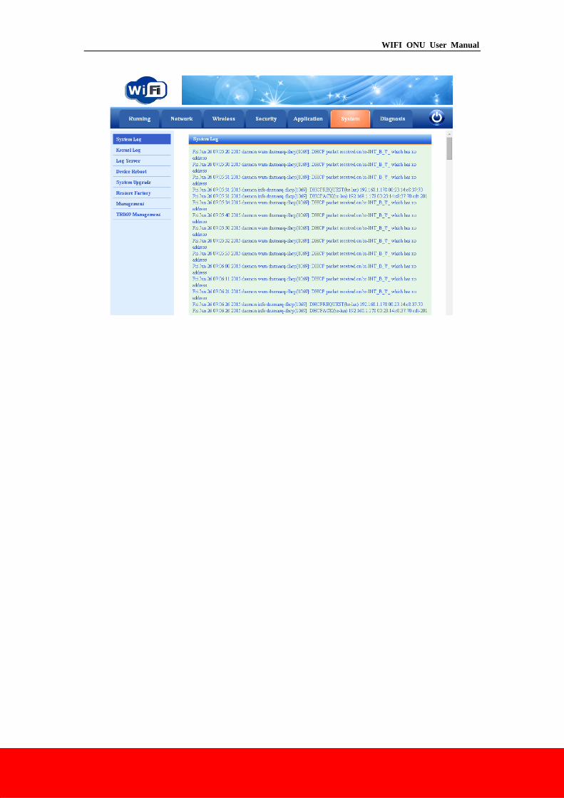
8.5 System Log
Log basic setting can be chosen to enable or disable log. Log pri includes Emergency,
Alert, Critical, Error, Warning, Notice, Information, Debugging, a total of eight categories. It
can be chosen into different log pri according to different operation situation. Click submit
button to finish relevant setting. Log events record relevant log events information that
happened, it can clean relevant log information and export log information. As displayed
below.
WIFI ONU User Manual