wireless lan connecting adapter installation manual
TRANSCRIPT
Wireless LAN Connecting Adapter<BRP069B41> <BRP069B42><BRP069B43> <BRP069B44>
<BRP069B45>
Installation Manual
4P481234-1

English 1
Wireless LAN Connecting Adapter <BRP069B41> Installation Manual
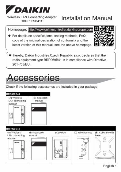
AccessoriesCheck if the following accessories are included in your package.
Homepage: http://www.onlinecontroller.daikineurope.com
�� For details on specifications, setting methods, FAQ, copy of the original declaration of conformity and the latest version of this manual, see the above homepage.
�� Hereby, Daikin Industries Czech Republic s.r.o. declares that the radio equipment type BRP069B41 is in compliance with Directive 2014/53/EU.
BRP069B41(A) Wireless LAN connecting adapter
(B) Installation manual
BRP069B42(A) Wireless LAN connecting adapter
(B) Installation manual
(C) Holder (D) Wire harness (E) Cable tie with base
English 2
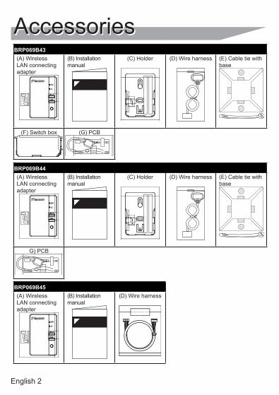
BRP069B43(A) Wireless LAN connecting adapter
(B) Installation manual
(C) Holder (D) Wire harness (E) Cable tie with base
(F) Switch box (G) PCB
BRP069B44(A) Wireless LAN connecting adapter
(B) Installation manual
(C) Holder (D) Wire harness (E) Cable tie with base
G) PCB
BRP069B45(A) Wireless LAN connecting adapter
(B) Installation manual
(D) Wire harness
Accessories
English 3
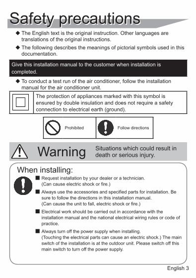
Safety precautions��The English text is the original instruction. Other languages are translations of the original instructions.
��The following describes the meanings of pictorial symbols used in this documentation.
Give this installation manual to the customer when installation is completed.
��To conduct a test run of the air conditioner, follow the installation manual for the air conditioner unit.
The protection of appliances marked with this symbol is ensured by double insulation and does not require a safety connection to electrical earth (ground).
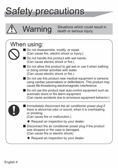
Warning Situations which could result in death or serious injury.
Prohibited Follow directions
When installing:� Request installation by your dealer or a technician. (Can cause electric shock or fire.)
� Always use the accessories and specified parts for installation. Be sure to follow the directions in this installation manual. (Can cause the unit to fall, electric shock or fire.)
� Electrical work should be carried out in accordance with the installation manual and the national electrical wiring rules or code of practice.
� Always turn off the power supply when installing. (Touching the electrical parts can cause an electric shock.) The main switch of the installation is at the outdoor unit. Please switch off this main switch to turn off the power supply.
English 4
Safety precautions
Warning Situations which could result in death or serious injury.
When using:� Do not disassemble, modify, or repair. (Can cause fire, electric shock or injury.)
� Do not handle this product with wet hands. (Can cause electric shock or fire.)
� Do not allow this product to get wet or use it when bathing or doing similar activities with water. (Can cause electric shock or fire.)
� Do not use this product near medical equipment or persons using cardiac pacemakers or defibrillators. This product may cause life-threatening electromagnetic interference.
� Do not use this product near auto-control equipment such as automatic doors or fire alarm equipment. (Can cause accidents due to erroneous equipment behavior.)
� Immediately disconnect the air conditioner power plug if there is abnormal odor or sound, when it is overheating, or smoking. (Can cause fire or malfunction.)
�� Request an inspection by your dealer.
� Disconnect the air conditioner power plug if the product was dropped or the case is damaged. (Can cause fire or electric shock)
�� Request an inspection by your dealer.
English 5
Safety precautions
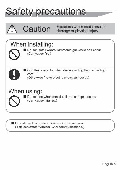
Caution Situations which could result in damage or physical injury.
� Do not use this product near a microwave oven. (This can affect Wireless LAN communications.)
When installing:� Do not install where flammable gas leaks can occur. (Can cause fire.)
� Grip the connector when disconnecting the connecting cord. (Otherwise fire or electric shock can occur.)
When using:� Do not use where small children can get access. (Can cause injuries.)
English 6
Wireless LAN connecting adapter
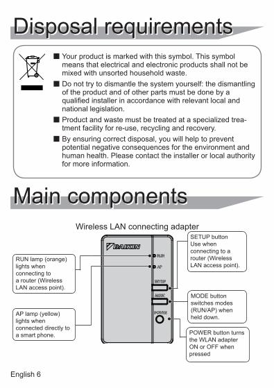
Disposal requirements� Your product is marked with this symbol. This symbol means that electrical and electronic products shall not be mixed with unsorted household waste.
� Do not try to dismantle the system yourself: the dismantling of the product and of other parts must be done by a qualified installer in accordance with relevant local and national legislation.
� Product and waste must be treated at a specialized trea-tment facility for re-use, recycling and recovery.
� By ensuring correct disposal, you will help to prevent potential negative consequences for the environment and human health. Please contact the installer or local authority for more information.
Main components
RUN lamp (orange) lights when connecting to a router (Wireless LAN access point).
AP lamp (yellow) lights when connected directly to a smart phone.
SETUP button Use when connecting to a router (Wireless LAN access point).
MODE button switches modes (RUN/AP) when held down.
POWER button turns the WLAN adapter ON or OFF when pressed
English 7
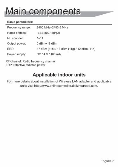
Main componentsBasic parameters:
Frequency range: 2400 MHz–2483.5 MHz
Radio protocol: IEEE 802.11b/g/n
RF channel: 1–11
Output power: 0 dBm~18 dBm
ERP: 17 dBm (11b) / 13 dBm (11g) / 12 dBm (11n)
Power supply: DC 14 V / 100 mA
RF channel: Radio frequency channel ERP: Effective radiated power
Applicable indoor unitsFor more details about installation of Wireless LAN adapter and applicable
units visit http://www.onlinecontroller.daikineurope.com.
English 8
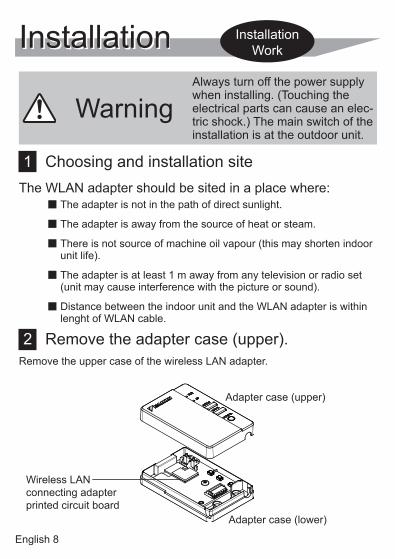
Installation
WarningAlways turn off the power supply when installing. (Touching the electrical parts can cause an elec-tric shock.) The main switch of the installation is at the outdoor unit.
1 Choosing and installation siteThe WLAN adapter should be sited in a place where:
� The adapter is not in the path of direct sunlight.
� The adapter is away from the source of heat or steam.
� There is not source of machine oil vapour (this may shorten indoor unit life).
� The adapter is at least 1 m away from any television or radio set (unit may cause interference with the picture or sound).
� Distance between the indoor unit and the WLAN adapter is within lenght of WLAN cable.
2 Remove the adapter case (upper).Remove the upper case of the wireless LAN adapter.
Installation Work
Wireless LAN connecting adapter printed circuit board
Adapter case (upper)
Adapter case (lower)
English 9
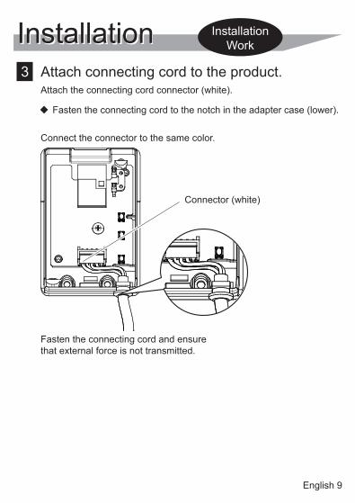
Installation 3 Attach connecting cord to the product.
Attach the connecting cord connector (white).
�� Fasten the connecting cord to the notch in the adapter case (lower).
Installation Work
Connect the connector to the same color.
Fasten the connecting cord and ensure that external force is not transmitted.
Connector (white)
English 10
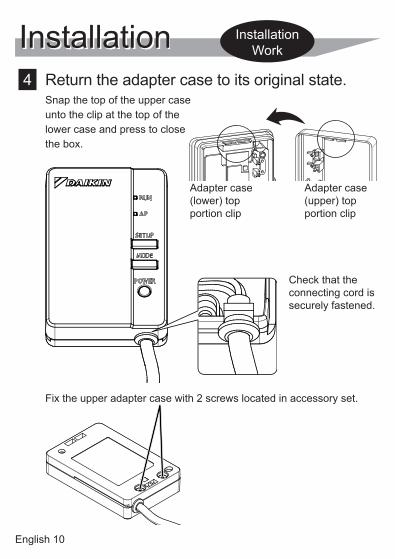
Installation 4 Return the adapter case to its original state.
Snap the top of the upper case unto the clip at the top of the lower case and press to close the box.
Fix the upper adapter case with 2 screws located in accessory set.
Adapter case (lower) top portion clip
Adapter case (upper) top portion clip
Check that the connecting cord is securely fastened.
Installation Work

English 11
Installation 5 Installation of Wireless LAN adapter
BRP069B41/B45Install WLAN adapter inside the indoor unit. For more details about installation of WLAN adapter to your model please visit http://www.onlinecontroller.daikineurope.com.
BRP069B42/B43/B44Install the WLAN adapter outside the indoor unit. There are two ways of installation A and B.
� TYPE APosition of the WLAN adapter on the wall/surface is fixed by screws. In this case double face tapes located in accessory set are not neccessary to fix the holder.
1. Fix the WLAN holder on the wall/surface with 2 screws located in accessory set.
2. Attach the WLAN adapter to the holder by sliding into it.
For more details about installation of WLAN adapter to your model please visit http://www.onlinecontroller.daikineurope.com.
Installation Work
Holes for screws
Holder

English 12
Installation� TYPE B
Position of the WLAN adapter on the wall/surface is fixed by double face tapes. In this case screws located in accessory set are not neccesary to fix the holder.
1. Attach two double face tapes located in accessory set to the back side of holder as shown below.
2. Fix the WLAN holder on the wall/surface with the double face tapes.
3. Make sure that holder is fixed to the wall/surface enough to bear the WLAN adapter.
4. Attach the WLAN adapter to the holder by sliding into it.
NOTE Wall/surface should be clean and degreased before attaching of the WLAN holder by double face tapes.
For more details about installation of WLAN adapter to your model please visit http://www.onlinecontroller.daikineurope.com
Installation Work
Double face tape
Holder
English 13
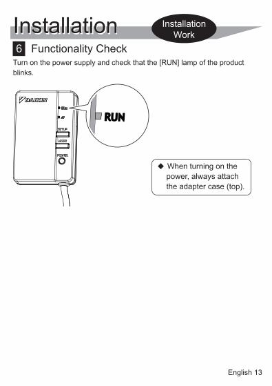
6 Functionality CheckTurn on the power supply and check that the [RUN] lamp of the product blinks.
Installation Installation Work
�� When turning on the power, always attach the adapter case (top).
English 14
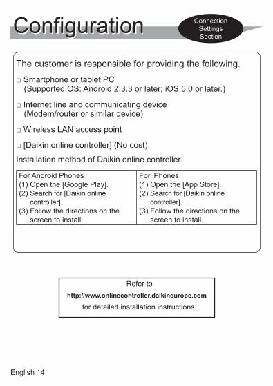
ConfigurationThe customer is responsible for providing the following.
□ Smartphone or tablet PC (Supported OS: Android 2.3.3 or later; iOS 5.0 or later.)
□ Internet line and communicating device (Modem/router or similar device)
□ Wireless LAN access point
□ [Daikin online controller] (No cost)
Installation method of Daikin online controller
For Android Phones(1) Open the [Google Play].(2) Search for [Daikin online
controller].(3) Follow the directions on the
screen to install.
For iPhones(1) Open the [App Store].(2) Search for [Daikin online
controller].(3) Follow the directions on the
screen to install.
Connection Settings Section
Refer tohttp://www.onlinecontroller.daikineurope.com
for detailed installation instructions.
English 15
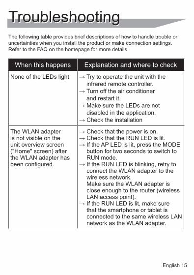
TroubleshootingThe following table provides brief descriptions of how to handle trouble or uncertainties when you install the product or make connection settings. Refer to the FAQ on the homepage for more details.
When this happens Explanation and where to check
None of the LEDs light → Try to operate the unit with the infrared remote controller.
→ Turn off the air conditioner and restart it.
→ Make sure the LEDs are not disabled in the application.
→ Check the installation
The WLAN adapter is not visible on the unit overview screen ("Home" screen) after the WLAN adapter has been configured.
→ Check that the power is on.→ Check that the RUN LED is lit.→ If the AP LED is lit, press the MODE
button for two seconds to switch to RUN mode.
→ If the RUN LED is blinking, retry to connect the WLAN adapter to the wireless network. Make sure the WLAN adapter is close enough to the router (wireless LAN access point).
→ If the RUN LED is lit, make sure that the smartphone or tablet is connected to the same wireless LAN network as the WLAN adapter.
English 16
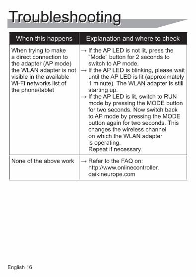
When this happens Explanation and where to check
When trying to make a direct connection to the adapter (AP mode) the WLAN adapter is not visible in the available Wi-Fi networks list of the phone/tablet
→ If the AP LED is not lit, press the "Mode" button for 2 seconds to switch to AP mode.
→ If the AP LED is blinking, please wait until the AP LED is lit (approximately 1 minute). The WLAN adapter is still starting up.
→ If the AP LED is lit, switch to RUN mode by pressing the MODE button for two seconds. Now switch back to AP mode by pressing the MODE button again for two seconds. This changes the wireless channel on which the WLAN adapter is operating. Repeat if necessary.
None of the above work → Refer to the FAQ on: http://www.onlinecontroller.daikineurope.com
Troubleshooting


4P481234-1 2017.05