rotex lan adapter - daikin
TRANSCRIPT

Installation manualROTEX LAN adapter English
Installation manual
ROTEX LAN adapter
RBRP069A61

Table of contents
Installation manual
2RBRP069A61
ROTEX LAN adapter4P509999-1B – 2018.10
Table of contents
1 About the documentation 21.1 About this document.................................................................. 2
2 About the product 22.1 Compatibility.............................................................................. 32.2 System requirements ................................................................ 3
3 About the box 33.1 To unpack the LAN adapter ...................................................... 3
4 Preparation 44.1 Installation site requirements..................................................... 44.2 Overview of electrical connections ............................................ 4
4.2.1 Router ......................................................................... 44.2.2 Indoor unit ................................................................... 44.2.3 Electricity meter .......................................................... 54.2.4 Solar inverter/energy management system ................ 5
5 Installation 55.1 Mounting the LAN adapter ........................................................ 5
5.1.1 To mount the rear casing to the wall........................... 65.1.2 To mount the PCB to the rear casing.......................... 6
5.2 Connecting the electrical wiring................................................. 65.2.1 To connect the indoor unit .......................................... 75.2.2 To connect the router.................................................. 75.2.3 To connect the electricity meter .................................. 75.2.4 To connect the solar inverter/energy management
system......................................................................... 75.3 Finishing the LAN adapter installation....................................... 8
5.3.1 LAN adapter serial number ......................................... 85.3.2 To close the LAN adapter ........................................... 8
6 Starting up the system 8
1 About the documentation
1.1 About this documentTarget audienceAuthorised installers
Documentation setThis document is part of a documentation set. The complete setconsists of:
▪ General safety precautions
▪ Safety instructions that you must read before installing
▪ Format: Paper (in the box of the indoor unit)
▪ Installation manual:
▪ Installation instructions
▪ Format: Paper (supplied in the kit)
▪ Installer reference guide:
▪ Installation instructions, configuration, application guidelines,…
▪ Format: Digital files on the ROTEX homepage
Latest revisions of the supplied documentation may be available onthe regional ROTEX website or via your dealer.
The original documentation is written in English. All other languagesare translations.
2 About the productThe ROTEX LAN adapter allows for app control of the ROTEX heatpump system and, depending on the model, allows for theintegration of the heat pump system in a Smart Grid application.
The LAN adapter is available in 2 versions:
Model FunctionalityRBRP069A61 App control + Smart Grid
applicationRBRP069A62 App control only
INFORMATION
Not all models are available in all sales regions.
Components: casinga a
bd b b
a
c
c
e
a Wall mounting holesb Knockout holes (wiring from the bottom)c Knockout holes (wiring from the rear)d Ethernet connectione Status LEDs
Components: PCB
X1A
X2A
X3A
X4A
b
a
LD1
LD2
LD3
LD4
X1A~X4A Connectorsa DIP switchb Status LEDs
Status LEDs
LED Description BehaviourLD1 Indication of power to the
adapter, and of normaloperation.
▪ LED flashing: normaloperation.
▪ LED NOT flashing: nooperation.
LD2 Indication of TCP/IPcommunication with therouter.
▪ LED ON: normalcommunication.
▪ LED flashing:communicationproblem.

3 About the box
Installation manual
3RBRP069A61ROTEX LAN adapter4P509999-1B – 2018.10
LED Description BehaviourLD3 Indication of
communication with theindoor unit.
▪ LED ON: normalcommunication.
▪ LED flashing:communicationproblem.
LD4(a) Indication of Smart Gridactivity.
▪ LED ON: Smart Gridfunctionality of theindoor unit is controlledby the LAN adapter.
▪ LED OFF: systemoperating in normaloperation conditions(space heating/cooling,production of domestichot water), or running inthe "Normaloperation"/"Freerunning" Smart Gridoperation mode.
(a) This LED is ONLY active for RBRP069A61 (present forRBRP069A62, but ALWAYS inactive).
2.1 CompatibilityMake sure your ROTEX system is compatible for use with the LANadapter (app control and/or Smart Grid applications). For moreinformation, see the installer reference guide of the ROTEX system.
2.2 System requirementsThe requirements posed on the ROTEX system depend on the LANadapter application/system layout.
App control
Item RequirementLAN adapter software It is recommended to ALWAYS
keep the LAN adapter softwareup-to-date.
Unit control method Make sure user interface setting[C‑07] is set to 2: RT Control.
Smart Grid application
Item RequirementLAN adapter software It is recommended to ALWAYS
keep the LAN adapter softwareup-to-date.
Unit control method Make sure user interface setting[C‑07] is set to 2: RT Control.
Domestic hot water settings To allow for energy buffering inthe domestic hot water tank:
▪ Domestic hot water setting[E-05] (DHW operation) MUSTbe set to "DHW" ([E-05]=1).
▪ Domestic hot water setting[E-06] (DHW tank type.) MUSTbe set to "DHWtank" ([E-06]=1).
Power consumption controlsettings
▪ Power consumption controlsetting [4‑08] (Mode) MUST beset to "Continuous" ([4‑08]=1).
▪ Power consumption controlsetting [4‑09] (Type) MUST beset to "Power" ([4‑09]=1).
INFORMATION
For instructions on how to perform a software update, seethe installer reference guide.
3 About the box
3.1 To unpack the LAN adapter1 Unpack the LAN adapter.
a
b
c
a Front casingb PCBc Rear casing
2 Separate the accessories.
a
a
a
a Accessories
Accessories: RBRP069A61
2× 1× 1×a b c
1×d
3× 3× 3×f
1×e f g h
4×i
1× 1×j k
Accessory RBRP069A61 RBRP069A62a Installation manual O Ob 6‑pole slide
connector for X1AO —
c 2‑pole slideconnector for X2A
O —
d 2‑pole slideconnector for X3A
O O
e Ethernet cable O Of Grommets O O

4 Preparation
Installation manual
4RBRP069A61
ROTEX LAN adapter4P509999-1B – 2018.10
Accessory RBRP069A61 RBRP069A62g Screws to mount
rear casingO O
h Plugs to mount rearcasing
O O
i Screws to mountPCB
O O
j Screw to closefront casing
O O
k Cable tie O —
4 Preparation
4.1 Installation site requirementsINFORMATION
Also read the maximum cable length requirements set outin "4.2 Overview of electrical connections" on page 4.
▪ Mind the following spacing installation guidelines:
>30 mm >30 mm
>90
mm
(a)
>160
mm
(b)
(a) Provide enough space to connect the Ethernet cablewithout exceeding its minimum bend radius (typically90 mm)
(b) Provide enough space to open the casing with a flat-bladescrewdriver (typically 160 mm)
▪ The LAN adapter is designed to be wall-mounted in dry, indoorlocations only. Make sure the installation surface is a flat andvertical non-combustible wall.
▪ The LAN adapter is designed to be mounted in the followingorientation only: with the PCB on the right-hand side in the casing,and the Ethernet connector facing the floor.
▪ The LAN adapter is designed to operate in ambient temperaturesranging from 5~35°C.
4.2 Overview of electrical connectionsConnectors
X4A
4NL
321
21
X1A
X2A
X3A
a1
A
b
c
a2
d
A RBRP069A61 onlya1 To solar inverter/energy management systema2 230 V AC detection voltageb To electricity meterc To indoor unit (P1/P2)d To router
Connections
Connection Cable section Wires Maximumcable length
Accessory cablesRouter (X4A) — — 50/100 m(a)
Field-supplied cablesIndoor unit (P1/
P2) (X3A)0.75~1.25 mm2 2(b) 200 m
Electricity meter(X2A)
0.75~1.25 mm2 2(c) 100 m
Solar inverter/energy
managementsystem +230 V ACdetection
voltage (X1A)
0.75~1.5 mm2 Depends onapplication(d)
100 m
(a) The Ethernet cable delivered as an accessory is 1 m long.It is, however, possible to use a field-supplied Ethernetcable. In this case, respect the maximum allowed distancebetween LAN adapter and router, which is 50 m in case ofCat5e cables, and 100 m in case of Cat6 cables.
(b) These wires MUST be sheathed. Recommended striplength: 6 mm.
(c) These wires MUST be sheathed. Recommended striplength: 6 mm.
(d) All wiring to X1A MUST be H05VV. Required strip length:7 mm. For more information, see "4.2.4 Solar inverter/energy management system" on page 5.
4.2.1 RouterMake sure the LAN adapter can be connected via a LAN connection.
The minimum category for the Ethernet cable is Cat5e.
4.2.2 Indoor unitFor power and communication with the indoor unit, the LAN adapteris connected to the indoor unit's P1/P2 terminals via a 2‑wire cable.There is NO separate power supply: the adapter gets its power fromthe indoor unit's P1/P2 terminals.

5 Installation
Installation manual
5RBRP069A61ROTEX LAN adapter4P509999-1B – 2018.10
4.2.3 Electricity meterIf the LAN adapter is connected to an electricity meter, make sure itis an electrical pulse meter.
Requirements:
Item SpecificationType Pulse meter (5 V DC pulse
detection)Possible number of pulses ▪ 100 pulse/kWh
▪ 1000 pulse/kWhPulse duration Minimum On
time10 ms
Minimum OFFtime
100 ms
Measurement type Depends on the installation:
▪ Single‑phase AC meter
▪ Three‑phase AC meter(balanced loads)
▪ Three‑phase AC meter(unbalanced loads)
INFORMATION
It is required that the electricity meter has a pulse outputthat can measure the total energy injected INTO the grid.
Suggested electricity meters
Phase ABB referenceSingle 2CMA100152R1000 B21 212-100Three 2CMA100166R1000 B23 212-100
4.2.4 Solar inverter/energy managementsystem
INFORMATION
Before installation, confirm that the solar inverter/energymanagement system is equipped with the digital outputsrequired to connect it to the LAN adapter. For moreinformation, see the installer reference guide.
Connector X1A is for the connection of the LAN adapter to the digitaloutputs of a solar inverter/energy management system, and allowsfor the integration of the ROTEX system in a Smart Grid application.
X1A/N+L supply a 230 V AC detection voltage to the input contact ofX1A. The 230 V AC detection voltage enables the detection of thestate (open or close) of the digital inputs and does NOT supplypower to the rest of the LAN adapter PCB.
Make sure X1A/N+L are protected by a fast acting circuit breaker(rated current 100 mA~6 A, type B).
The rest of the wiring to X1A differs depending on the digital outputsavailable on the solar inverter/energy management system and/or onthe Smart Grid operation modes that you want the system to run in.
Smart Grid operation mode SG0
(X1A/1+2)
SG1
(X1A/3+4)Normal operation/Free running
NO Smart Grid application
Open Open
Recommended ON
Energy buffering in the domestichot water tank and/or the room,WITH power limitation.
Closed Open
Smart Grid operation mode SG0
(X1A/1+2)
SG1
(X1A/3+4)Forced OFF
Deactivation of outdoor unit andelectrical heater operation incase of high energy tariffs.
Open Closed
Forced ON
Energy buffering in the domestichot water tank and/or the room,WITHOUT power limitation.
Closed Closed
For more information, see the installer reference guide.
5 Installation
5.1 Mounting the LAN adapterThe LAN adapter is mounted to the wall by way of the mountingholes (a) in the rear casing. Before mounting the rear casing to thewall, you have to remove some knockout holes (b)(c), depending onhow you want to route the wiring and insert it into the adapter.
You can route and insert the wiring from the bottom or from the rear.Respect the following rules and restrictions:
Wiring Possibilities and restrictionsWiring routed and inserted fromthe bottom
▪ ONLY for surface wiring routedfrom the bottom.
▪ When routing wiring from thebottom, ALWAYS let it enterthe adapter via the holes in thebottom of the casing (b). It isNOT allowed to clamp thiswiring between the casing andthe wall and let it enter via theholes in the rear (c).
▪ The wiring for X1A and X4AMUST be routed and insertedfrom the bottom. The wiring forX2A and X3A CAN be routedand inserted from the bottom(or from the rear).
▪ When routing and insertingwiring from the bottom,remove the required knockoutholes in the bottom of thecasing (b) and replace themwith the grommets from theaccessory bag.
Wiring routed and inserted fromthe rear
▪ ONLY for in‑wall wiringentering the adapter from therear.
▪ The wiring for X2A and X3ACAN be routed and insertedfrom the rear (or from thebottom). The wiring for X1Aand X4A CANNOT be routedand inserted from the rear.
▪ It is NOT allowed to routewiring from the bottom, clampit between the casing and thewall, and let it enter via theholes in the rear (c).
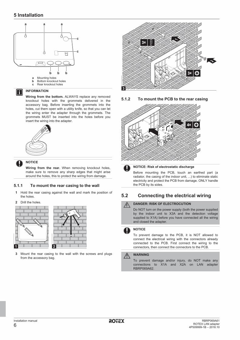
5 Installation
Installation manual
6RBRP069A61
ROTEX LAN adapter4P509999-1B – 2018.10
a a
b b b
a
c
c
a Mounting holesb Bottom knockout holesc Rear knockout holes
INFORMATION
Wiring from the bottom. ALWAYS replace any removedknockout holes with the grommets delivered in theaccessory bag. Before inserting the grommets into theholes, cut them open with a utility knife, so that you can letthe wiring enter the adapter through the grommets. Thegrommets MUST be inserted into the holes before youinsert the wiring into the adapter.
NOTICE
Wiring from the rear. When removing knockout holes,make sure to remove any sharp edges that might arisearound the holes, this to protect the wiring from damage.
5.1.1 To mount the rear casing to the wall1 Hold the rear casing against the wall and mark the position of
the holes.
2 Drill the holes.
1 2
3 Mount the rear casing to the wall with the screws and plugsfrom the accessory bag.
3
1
2
3×
3×
5.1.2 To mount the PCB to the rear casing
4×
NOTICE: Risk of electrostatic discharge
Before mounting the PCB, touch an earthed part (aradiator, the casing of the indoor unit, ...) to eliminate staticelectricity and protect the PCB from damage. ONLY handlethe PCB by its sides.
5.2 Connecting the electrical wiringDANGER: RISK OF ELECTROCUTION
Do NOT turn on the power supply (both the power suppliedby the indoor unit to X3A and the detection voltagesupplied to X1A) before you have connected all the wiringand closed the adapter.
NOTICE
To prevent damage to the PCB, it is NOT allowed toconnect the electrical wiring with the connectors alreadyconnected to the PCB. First connect the wiring to theconnectors, then connect the connectors to the PCB.
WARNING
To prevent damage and/or injury, do NOT make anyconnections to X1A and X2A on LAN adapterRBRP069A62.

5 Installation
Installation manual
7RBRP069A61ROTEX LAN adapter4P509999-1B – 2018.10
5.2.1 To connect the indoor unit
INFORMATION
▪ In the indoor unit switch box, the cable is connected tothe same terminals the user interface is connected to(P1/P2). For more information, see the installationmanual of the indoor unit.
▪ The 2 wires from the cable are NOT polarised. Whenconnecting them to the terminals, their polarity doesNOT matter.
1 When entering the wiring from the bottom: inside the LANadapter casing, ensure strain relief by routing the cable alongthe indicated cable path.
2 Connect indoor unit terminals P1/P2 to LAN adapter terminalsX3A/1+2.
X4A
X1A
X2A
X3AP2P1
5.2.2 To connect the router
X4A
X1A
X2A
X3A
NOTICE
To prevent communication problems due to cablebreakdown, do NOT exceed the minimum bend radius ofthe Ethernet cable.
5.2.3 To connect the electricity meter
INFORMATION
This connection is ONLY supported by LAN adapterRBRP069A61.
1 When entering the wiring from the bottom: inside the LANadapter casing, ensure strain relief by routing the cable alongthe indicated cable path.
2 Connect the electricity meter to LAN adapter terminalsX2A/1+2.
S1S
21
X4A
X1A
X2A
X3A
INFORMATION
Mind the polarity of the cable. The positive wire MUST beconnected to X2A/1; the negative wire to X2A/2.
WARNING
Make sure to connect the electricity meter in the correctdirection, so that it measures the total energy injectedINTO the grid.
5.2.4 To connect the solar inverter/energymanagement system
INFORMATION
This connection is ONLY supported by LAN adapterRBRP069A61.
INFORMATION
How the digital inputs are connected to X1A depends onthe Smart Grid application. The connection described inthe instructions below is for the system to run in the"Recommended ON" operation mode. For moreinformation, see the installer reference guide.
WARNING
Make sure X1A/N+L are protected by a fast acting circuitbreaker (rated current 100 mA~6 A, type B).
WARNING
When connecting the wiring to LAN adapter terminal X1A,make sure each wire is securely fastened to theappropriate terminal. Use a screwdriver to open the wireclamps. Make sure the bare copper wire is fully insertedinto the terminal (bare copper wire CANNOT be visible).
1
32
1 Ensure strain relief by fastening the cable with a cable tie to thecable tie mounting.
2 Provide a detection voltage to X1A/N+L. Make sure X1A/N+Lare protected by a fast acting circuit breaker (100 mA~6 A, typeB).
3 For the system to run in the "Recommended ON" operationmode (Smart Grid application), connect the digital outputs of thesolar inverter/energy management system to LAN adapterdigital inputs X1A/1+2 LAN.

6 Starting up the system
Installation manual
8RBRP069A61
ROTEX LAN adapter4P509999-1B – 2018.10
X4A
X1A
X2A
X3A
S1S LN
4
LN
321
5.3 Finishing the LAN adapterinstallation
5.3.1 LAN adapter serial numberBefore closing the LAN adapter, note down its serial number. Thisnumber can be found on the adapter's Ethernet connector(bottommost number on X4A). Note it down in the table below.
Serial number
INFORMATION
The serial number is used during the configuration of theLAN adapter. For more information, see the installerreference guide.
5.3.2 To close the LAN adapter1 Put the front casing to the rear casing and tighten the screw.
1
2
3
1×
6 Starting up the systemThe LAN adapter gets its power from the indoor unit. For the LANadapter to function, therefore make sure it is connected to the indoorunit, and the indoor unit is powered on.
After powering on the system, it can take up to 30 minutes beforethe LAN adapter is operational, depending on the system layout.
At all times make sure the LAN adapter software is up-to-date. Forhow to perform a software update and configure the system, see theinstaller reference guide.


ROTEX Heating Systems GmbHLangwiesenstraße 10D-74363 Güglingenwww.rotex-heating.com
Unsere Partner im AuslandOur partners abroad • Unsere Partner im AuslandNos partenaires à l’étranger • Le nostre sedi all'esteroNeustros representantes en el extranjeroNasi partnerzy za granicą • Naši partneři v zahraničí
http://de.rotex-heating.com > ueber-rotex > international 4P509999-1B 2018.10
© R
OTE
X ∙
Sub
ject
to c
hang
e an
d co
rrec
tion
4P509999-1 B 0000000C