work method soilinvestigation
TRANSCRIPT

PT. TAKENAKA DOBOKU INDONESIA
Civil Engineering and Construction Bank Resona Perdania Building 6th Floor,Jl. Jend. Sudirman Kav. 40-41, Jakarta 10210, Indonesia
Tel: 021-570-1995 Fax: 021-570-1938
METHOD STATEMENT
EXPLORATORY DRILLING
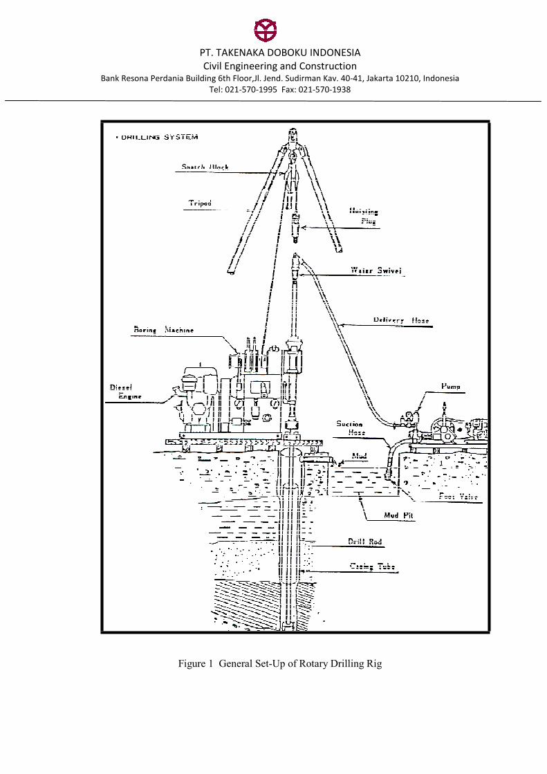
The exploratory boreholes are generally drilled using rotary type drilling rig. Figure 1 shows the
general set-up of a rotary drilling rig. The common diameters of the exploratory boreholes are 89 to
100 mm. The drilling is generally carried out in one or both of the following methods:
a. Rotary Core Drilling
Rotary core drilling is one of drilling methods to advance an exploratory borehole with core sample
retrieved for visual examination. It is used for drilling in soil formation and especially in rock
formation. The method is however not suitable for very soft to soft clay as the suction during
withdrawal of core barrel disturbs the subsoil. Core catcher may be required for drilling in loose
sand. In the drilling process, a core barrel is lowered to the bottom of the borehole by drill rods. The
borehole is advanced by rotating the core barrel with gentle thrust actions. When the core barrel is
full with soil, generally in 50 to 100 cm penetration, the core barrel is withdrawn from the borehole.
With the help of water pressure pumped through the drill rod, the soil inside the core barrel is pushed
out. The retrieved core sample is then stored in core boxes in depth order.
b. Rotary Wash Boring
In rotary wash boring method, a drilling bit is lowered to the bottom of the borehole by drill rods.
The borehole is advanced by rotating the drilling bit with gentle thrust actions and, at the same time,
muddy water is pumped through the drilling bit to flush out the soil cuttings. The muddy water also
serves as the coolant for the drill bit and stabilizes the borehole from collapsing or caving in. Thick
bentonite slurry is often used as drilling fluid which may effectively stabilize the borehole without
the use of casing pipes. Rotary wash boring method is used for drilling in soil formation especially in
very soft to soft clay formation because the method relatively produces lesser disturbance compared
to rotary core drilling method.
When the drilling reaches to the anticipated depth for undisturbed sampling or other in-situ tests, the
drill bit is gently moved up and down while the muddy water is continuously pumped to remove the
soil cuttings. The borehole is considered clean when the muddy water flowing out from the borehole
is free from the cuttings. The drill bit is then withdrawn from the borehole.
c. Borehole Stabilization
Flush joint casing pipes that suit the desired borehole diameter are commonly installed to prevent the
borehole wall from collapsing and to maintain a clean hole. If the borehole is sunk in soil layers
having high potential of collapsing, casing pipes have to be installed immediately after the advance
of the borehole to about 0.5m above the bottom of the borehole. In stable soil layers, casing pipes are
usually installed in upper weak ground only to prevent necking of the borehole and serve as guide
pipe. Muddy water or bentonite slurry is sometimes used as drilling fluid, which can effectively
stabilize the borehole without the use of casing pipes. Drilling fluid also serves as coolant in drilling
process.
PT. TAKENAKA DOBOKU INDONESIA
Civil Engineering and Construction Bank Resona Perdania Building 6th Floor,Jl. Jend. Sudirman Kav. 40-41, Jakarta 10210, Indonesia
Tel: 021-570-1995 Fax: 021-570-1938
Figure 1 General Set-Up of Rotary Drilling Rig

PT. TAKENAKA DOBOKU INDONESIA
Civil Engineering and Construction Bank Resona Perdania Building 6th Floor,Jl. Jend. Sudirman Kav. 40-41, Jakarta 10210, Indonesia
Tel: 021-570-1995 Fax: 021-570-1938
METHOD STATEMENT
STANDARD PENETRATION TEST
The purpose of performing Standard Penetration Test (SPT) is to determine relative density or
consistency of subsoil. The soil sample obtained from the test may be used for soil identification and
laboratory index property tests.
In carrying out the test, a split barrel sampler of 50mm outer diameter as sown in Figure 2 is lowered
to the bottom of the borehole by drill rods. The sampler is then driven into the soil for 450 mm
penetration by an automatic free-fall hammer of 63.5 kg in weight, over a falling height of 760mm.
Figure 3 shows a typical automatic hammer.
The blow counts of hammer in penetrating the split barrel into soil are recorded. The first 150 mm
penetration is regarded as seating drive and the number of blows to achieve this penetration is not
included in the SPT N-value. The cumulative numbers of blow counts required for the last 300 mm
penetration is recorded as the N-value. The recovered soil sample from the split barrel is then kept in
a plastic jar for soil identification in office.
The recording of blow counts depends on the standard or code of practice. In British Standard, the
blow counts are recorded for every 75 mm penetration. In ASTM Standard, the blow counts are
recorded for every 150 mm penetration. In some Japanese practices, the blow counts are taken at the
first 150 mm seating drive and then at every 100 mm penetration for the remaining 300 mm drive.
A = 1.0 to 2.0 in. (25 to 50 mm)
B = 18.0 to 30.0 in. (457 to 762 mm)
C = 1.375 0.005 in. (34.93 0.13 mm)
D = 1.50 0.05 - 0.00 in. (38.1 1.3 - 0.0 mm)
E = 0.10 0.02 in. (2.54 0.25 mm)
F = 2.00 0.05 in. - 0.00 in. (50.8 1.3 - 0.0 mm)
G = 16.0o to 23.0o
Figure 2 Standard Penetration Test Split Barrel Sampler

PT. TAKENAKA DOBOKU INDONESIA
Civil Engineering and Construction Bank Resona Perdania Building 6th Floor,Jl. Jend. Sudirman Kav. 40-41, Jakarta 10210, Indonesia
Tel: 021-570-1995 Fax: 021-570-1938
Figure 3 Automatic and Self Tripping Free Fall Drive Hammer
PT. TAKENAKA DOBOKU INDONESIA
Civil Engineering and Construction Bank Resona Perdania Building 6th Floor,Jl. Jend. Sudirman Kav. 40-41, Jakarta 10210, Indonesia
Tel: 021-570-1995 Fax: 021-570-1938
METHOD STATEMENT
SOIL SAMPLING
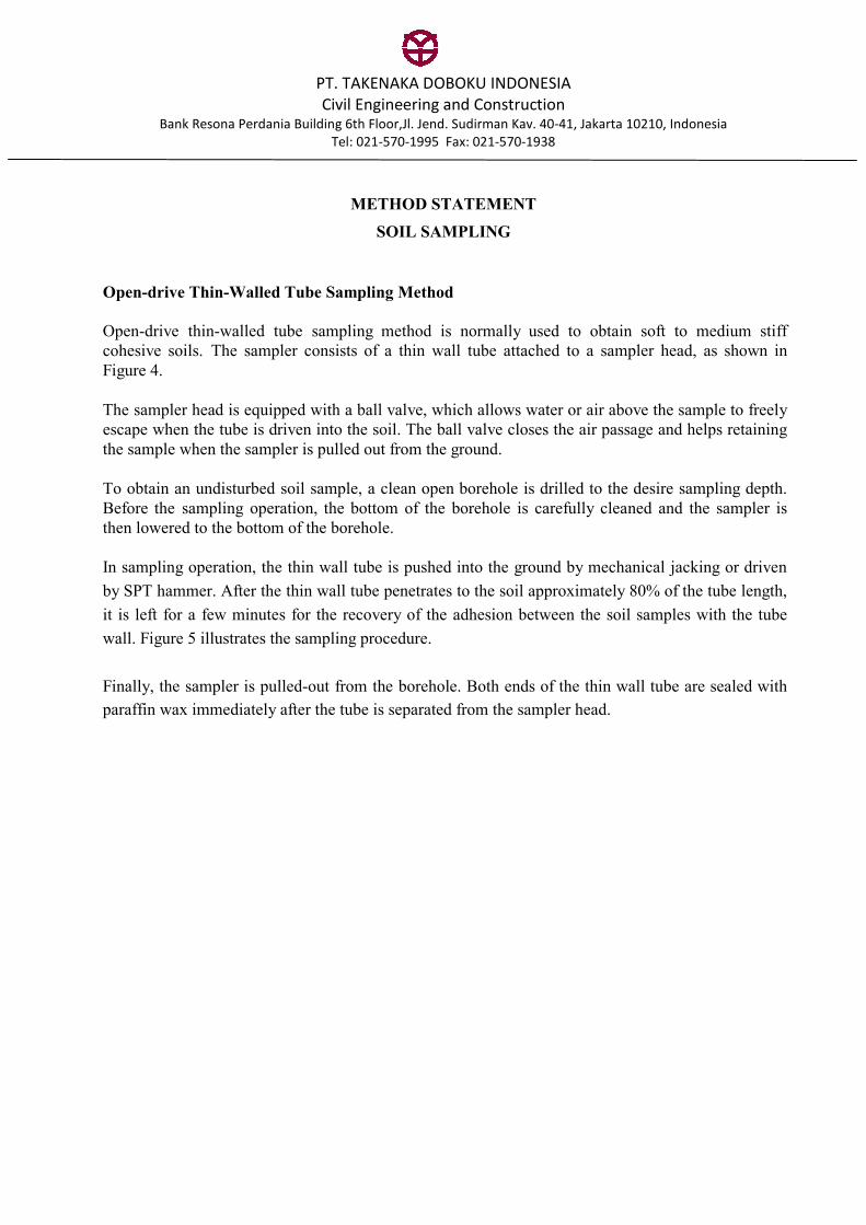
Open-drive Thin-Walled Tube Sampling Method
Open-drive thin-walled tube sampling method is normally used to obtain soft to medium stiff
cohesive soils. The sampler consists of a thin wall tube attached to a sampler head, as shown in
Figure 4.
The sampler head is equipped with a ball valve, which allows water or air above the sample to freely
escape when the tube is driven into the soil. The ball valve closes the air passage and helps retaining
the sample when the sampler is pulled out from the ground.
To obtain an undisturbed soil sample, a clean open borehole is drilled to the desire sampling depth.
Before the sampling operation, the bottom of the borehole is carefully cleaned and the sampler is
then lowered to the bottom of the borehole.
In sampling operation, the thin wall tube is pushed into the ground by mechanical jacking or driven
by SPT hammer. After the thin wall tube penetrates to the soil approximately 80% of the tube length,
it is left for a few minutes for the recovery of the adhesion between the soil samples with the tube
wall. Figure 5 illustrates the sampling procedure.
Finally, the sampler is pulled-out from the borehole. Both ends of the thin wall tube are sealed with
paraffin wax immediately after the tube is separated from the sampler head.

PT. TAKENAKA DOBOKU INDONESIA
Civil Engineering and Construction Bank Resona Perdania Building 6th Floor,Jl. Jend. Sudirman Kav. 40-41, Jakarta 10210, Indonesia
Tel: 021-570-1995 Fax: 021-570-1938
Figure 4 Open Drive Sampler
Figure 5 Operation of Open-Drive Sampling

PT. TAKENAKA DOBOKU INDONESIA
Civil Engineering and Construction Bank Resona Perdania Building 6th Floor,Jl. Jend. Sudirman Kav. 40-41, Jakarta 10210, Indonesia
Tel: 021-570-1995 Fax: 021-570-1938
METHOD STATEMENT
WATER STANDPIPE INSTALLATION
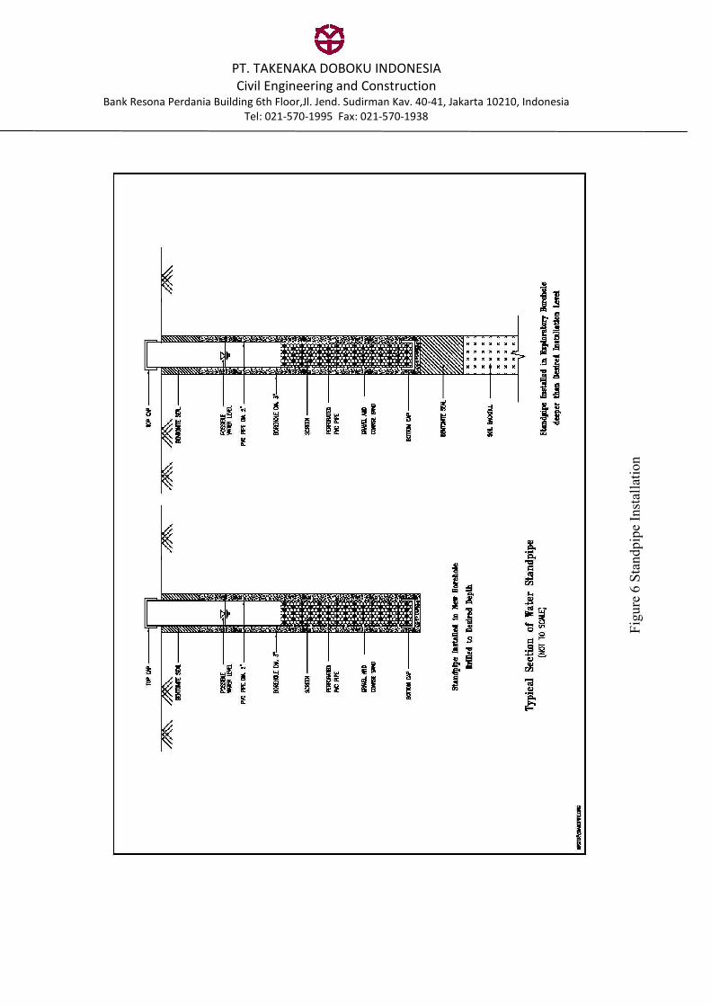
Standpipes are usually installed for the purpose of groundwater monitoring. The depth of the
standpipe is governed by the expected depth of the groundwater level to be monitored and
expected fluctuation of the water levels.
Standpipe consists of PVC pipe with 2 inches in diameter, which is sufficient for inserting dip-
meter to measure the groundwater levels. The pipe is perforated throughout its length except at
the top 1 to 2m and is wrapped with nylon mesh before inserting into the borehole. Figure 6
shows a typical setup of standpipe.
To install the standpipe, a borehole is sunk beforehand to a desired installation depth. The
perforated PVC pipe is then inserted into the borehole and the annular space between the pipe
and the borehole is filled with gravel to form a filter layer. When the gravel filter reaches to
approximately 1m below the ground, bentonite instead of gravel is filled to form a seal layer
preventing the surface running water to enter the standpipe and giving false result.
If the standpipe is installed in a completed exploratory borehole that is usually much deeper than
required depth of the standpipe, the bottom of the borehole is filled with local soil to 1m below
the desired installation depth. Bentonite of 1 m thick is then filled to the bottom of the borehole
to form a seal to prevent the influence of different piezometric heads from underlying soil layers.
The groundwater level in the standpipe is generally monitored by means of measuring tape.
When the groundwater is deep and not visible by using measuring tape, a dip-meter is used.
Either beep-sound or display may be activated when the probe of the dip-meter touches the
groundwater, indicating the depth of groundwater level.
PT. TAKENAKA DOBOKU INDONESIA
Civil Engineering and Construction Bank Resona Perdania Building 6th Floor,Jl. Jend. Sudirman Kav. 40-41, Jakarta 10210, Indonesia
Tel: 021-570-1995 Fax: 021-570-1938
Figure 6 Standpipe Installation