work zone ‘traffic ma[lagemlent synthesis zone ‘traffic ma[lagemlent synthesis: ... of the data...
TRANSCRIPT

Publication No. FHWA-TS-89-034July 1989
U.S.Departmentof Transportation
FederalHghwayAdministration
Work Zone ‘Traffic Ma[lagemlentSynthesis:Selection And Application Of Flashin!~ Arrow Pane!s
Research, Developmetlt, and TechnologyTurner. Fairbank Highway Research Center
6300 Georgetown PikeMcLean, Virginia 22101.2296

NOTICE
This document is disseminated under the sponsorship of theDeparknent of Transportation in the interest of informationexchange. The United States Government assumes no liabilityfor its contents or use thereof.
The Cov.ker<ts of tlnis report refj.ect the views of thecontractors who are responsible for the facts and the accuracyof the data presented herein. The contents do not necessarilyreflect the official views or policy of the Department ofTransportation.
The United states Government does not endorse products ormanufacturers. Trademarks or manufacturers ‘ names appearherein only because they are considered essential to theobject of this document.
TecWicalReprt~enbt ionPage
,.RePrt No.
FHWA-TS-89-034
1. Title a“d S“tiitle‘2”-’”’”’’-”’1””0” G
Work Zone TrafficManagement Synthesis L
Selectionand Applicationof Flashin86.per foming orga”i.ation me
Arrow Panels S. Per fomi”q Orga”i =tio” Reprt NO.
‘. A“ttir, s)
ErrolC.Noel,Ziad A. Sabra,Conrad L.Dudek
9.Pwfoming Orga”izati.” Nm and Mdress 10. work unit No. (~lS)
NCP 3A9a 0073Contractor DanielConsultants,Inc. 11. ti”tract or Grant m.
CoIumbia, Maryland DTFH61-88-X-000’Subcontractor:Dudek & Assoc.,Bryan,Texas 13. m of Rewrt a“d Brim Mrti
2. sp”soci”g AgQnq Nam and hddr.aS
FederalHighway Administration FinalReportTurner-FairbankHighway ResearchCenter May 1988”-May 19896300Georgetwon Pike 14. Swmoring Menq Me
McLean, Virginia22101-229615.suml-”tary Notes
FHWA ContractManager: GuentherLerch,HRT.20
16. -tract
This reportisa synthesisof researchfindingsand currentpracticesi:ntheselectionand applicationof arrow panelsin work zones. The informationpresentedhere is based o~la review of researchreportsand work zonemanuals of a selectionof stateand cityfzighv~ayagencies,discussionswithhigh way officials,and field observation of a selectionof highwayconstructionprojects.The reportpresentsan assessmentof the state-of-the-practiceand makes recommendations for further research andspecificationinclusionsin the futurerevisiOn~Of the ~ ~ ~TrafficControlDevices.
17.KeyWordsI
18.Distribution Sbat_t
‘OrkzOnes’aflashingarrow panels,mini-panels No restrictions.This document is
availabll:to the pubIicthrough theNationalTechnicalInformation
= -rity Classif. (of tii. rewrt) 20 ~ity C1aSSif (of this :~ge)
Fom ~ F 17W.7 (8-72) RePr&uctio” Of -1.td W9. aULtiKiti
i

APPROXIMATE CONVERSIONS TO S1 UNITS
jymbol WhenYouKnow MultiplyBy ToHnd Symbol
LENGTH
in iwhes 25,4 milhmetresn
mmfeet 0.305 mettes m
yd yads 0,914 metmsmi miles 1.61 kilometres ;m
AREA
iti square i“chs 66.2W
miltimetres sq.ar~ mtisquare feet 0,093 metr~ qwr~ M
yff square yards 0.636 metre q“.rd mzac acres 0,405 htiar% ham? square miles 2.59 kilometrs ,Qua,d kmz
VOLUMEf)02 fluid .unms 29.57 miltifitres mlgal gallons 3,785 fit,as Lna chic fwt 0.026 metrm c@ed mxyds CA i. yards 0.765 met,,, Cbed m,
IOTE: Volumes greater than 1000 L shall b shown in mz.
MASS52 OUnws 26.35 gramslb
9pounds 0.4s kifqrams kg
T shofl tons (2o0o b) 0.907 m-a9rams Mg
TEMPERATURE (exact)
‘F Fahrenheti 5( F-32)/9 Celcius =Ctemperature temperature
Slkthesvmbl for the international Svstem.f Measurement
mmm
k:
mm2dha
kti
mLL
mam]
:9Mg
-c
LENGTH
millimetres 0.0s9 inchesretires 3 .m f~metres 1.09 yardstilometres 0.621 miles
AREA
milhmetres sq”ard 0,00?6 Sq”a,e ,Whsmatrm WUard 10,7M square fwthtia,~ 2,47 acreskilometres sq”ar& 0.366 square mibs
innydmi
itiftza.miz
VOLUME
milhhtres 0.034 fluid o“n~s fl Ozht,ffi 0.264 gallons galmetres chti 35,s45 CWlc twt ft$metres c*4 1.308 .ti. yards ydz
MASS
grams 0,035 ounwsKlqram$
OZ2.205 pounds
m%a9rams 1.102 shotitons(2000b) ~
TEMPERATURE (exact)
Glcius 1,6C + 32 Fahrsnhefi OFtemperature temperature
‘F 32 98.6 ;;2–40 0 40 80
l,, ,,, ,,, ,,, ,,J120 lm 200
f+,,.:: -20 0 20
3;0m 80 ;?
(Revi4 ADtil 1989)

TABL,E OF CO~E~S
Page
LIST OF FIGURES ...................................LIST OF TABLES .......,...............,..-..-........
I. INTRODUCTION ........,......-........,...............A. Driver Needs ...................................B. Driver Understanding of Arrow Panels ..........c. Placement of Arrow Panels for La!ne Closures ...D. Effectiveness of Arrow Panels in Lane
closures ......................................
II. DESIGN REQUIREMENTS AND SPECIFICATIONS ............A. Manual on Uniform Traffic Control Devices
(MUTCD) .......................................B. state and Local Specifications ................
1. Panels ....................................2. Lamps .....................................3. Mounts ....................................4. Operation Controls ........................5. Power Supply ...............................
c. Design Specifica~zions of Non-Standard ArrowPanels ...............-.....-.........,.......-.
D. crashworthiness <Of Arrow Panels ..............
III. APPLICATIONS IN PRACTICE ..........................A. MUTCDRewirementS ............................B. Current Use of Standard Arrow Panels ..........
1. Left and Right Lane Closures ...............2. Center Lane Closures ......................3. Multi-Lane Closures .......................4. Moving Maintenance Lane Closure
Operations ................................
5. shoulder Closure ..........................6. Lane Diversj.ons ...........................7. Traffic Splj,ts ............... ............
c. Summary of Current Practices .................-D. Current Use of Non-Standard Arrow Panels ......
1. State Goverz?ments ............-..,..........2. Municipalities ..................>..........3. Utility Companies ............... .........
IV. MAINTENANCE AND COSIT OF ARROW PANELS ..............A. Maintenance ...................................B. Cost of E~ipment .............................
v. CONCLUSIONS .......................................
VI. RECO~ENDAT IONS ...................................A. Arrow Panel Applications ......................B. Arrow Panel Specifications ....................c. Further Research on Arrow Panels ..............
ivv
1
1
26
7
11
11
11
12121217
1720
232325252933
363641474749495154
565657
59
62626465

Page
LIST OF REFE~NCES ...................................... 67
LIST OF FIGUUS
Figure 1.
Figure 2.Figure 3.Figure 4.Figure 5.
Figure 6.
Figure 7.
Figure 8.
Figure 9.
Figure 10.
Figure 11.
Figure 12.
Figure 13.
Fiqure 14.
Figure 15.
Figure 16.
Figure 17.
Fiqure 18.
Figure 19.Figure 20.
Figure 21.
Figure 22.
Figure 23.
Designation of information handling zonesrelated to positive guidance procedure .....Arrow panel modes... ........................Lamp spacing details for the arrow panel ...Lamp spacing details .......................Configuration of standard and non-standard arrow panels ......................Application of the arrow panel in typicalright lane closures ........................Application of the arrow panel in leftlane closures ..............................Placement of the arrow panel for typicalright lane closures in Michigan andPennsylvania ...............................Application of the arrow panel in laneclosures on local streets ..................Arrow panel applications in multi-laneclosures ...................................Arrow panel applications in center laneclosures on urban and rural roadways .......Proposed TCDH revision for use of onearrow panel in center lane closure .........Application of arrow panels in multi-laneclosures ...................................Moving-maintenance lane closure on urbanarterials ..................................Application of the arrow panel in ruralmoving operations on four and six-lanedivided highways ...........................Application of the arrow panel in movingoperations for sinqle and multi-laneclosures ...................................Application of the arrow panel for movingoperations .................................Application of the caution bar mode forshoulder closure ...........................Traffic control for shoulder closure .......Application of the arrow panel incrossovers .................................Application of the arrow panel incrossovers with lane reductions ............Lane shift without lane closure andarrow panel ................................Application of the arrow panel in typicaltraffic split ..............................
34
1415
21
26
27
28
30
31
32
34
35
37
38
39
40
4243
44
45
46
48
Page
Figure 24. Non-standard arrow panel on an interstatehighway .................................... 50
Figure 25. Use of mini-arrow panels on local streets .. 52Figure 26. Use of mini-arrow panels on local streets .. 53
LIST OF TABLES
Table 1. Sumary of arrol? panel specifi(:ations ........ 12Table 2. Non-standard arl?ow panel specijEications ...... 18Table 3. Non-standard ar]:ow panel specifications
(Table 2 continued) ................ .......... 19Table 4. Use of arrow panels in work zo]nes ............ 24Table 5. Cost of arrow panels ......................... 58

Arrow panels are sign panels with a matrix of lights capable ofdisplaying an illuminated flashing arrow or sequential arrowpattern or an illuminated flashing warning. Arrow panelsprovide advance warning to motorists when the travel lanes areclosed or diverted or when work is being done on the shoulder.Arrow panels are often used in conjunction with other trafficcontrol devices such as construction warning signs andchannelization devices.
General guidelines for the design, application, and operationof standard arrow panels are presented in Sections 6E-7 through6E-9 on the Manual on Uniform Traffic Control Clevices (MUTCD)(1) . Since their introduction to the ~TCD in 1977, standardarrow panels are widely used by state highway d~epartments,municipalities, utility companies, and cc>ntractors. The arrowpanel is primarily used far lane closures. Other applicatTLonsof the arrow panel include lane diversion, traffic splits,shoulder closure, and lane closure during movir]g-maintenanceactivities.
This synthesis discusses current practices in the design alndapplication of arrow panels based on a review (If the literatureand state standards, field observations, and discussions withstate highway officials in California, Illinois, Maryland,Michigan, New York, Virgi:nia, and Pennsylvania. Discussionswere also held with local highway officials in San Francisco,Washington, D.C., Chicago, Detroit, New York City, BaltimOre,Richmond, and Philadelphia.
A. Driver NeedS. Despite the use of conventional highway workzone warning signs and channelizing devices for lane closures,drivers must still make several critical decisions quickly.Prior to changing lanes, drivers must detect, recognize, andcomprehend visual cues and then decide on the appropriateresponse. These actions become increasingly demanding when thedriver does not obtain all the necessa~ information, isoverloaded with information, or the infctrmation is confusing.These are the areas where! the potential for serious accidentsis high. Proper selection and installation of traffic controldevices can help guide tkle motorist on the approach to andthrough the work zone.
Positive guidance in work zones reduces the risk of accidents,provides longer advance b~arning sign detection, promotesearlier merging into an open lane, and ~!acilitates driverpassage through the visu~~l clutter of construction andmaintenance e~ipment, alignment shifts,, work crews and t:rafficcontrol devices. The driver’s information and guidance n(seds
1

subareas as shown in Figure 1:
1. advance Zone - where hazards or inefficiencies do notyet affect the driver’s tack.
2. ApDroach Zone - where the driver must detect andrecognize the hazard ahead. This zone corresponds tothe decision sight distance minus the stopping sightdistance. The American association of State Highwayand Transportation Officials (AASHTO) (~) reC09niZeSthat stopping sight distances are often inade~atewhen drivers must make complex or instantaneousdecisions, when information is difficult to perceive,or when unexpected or unusual maneuvers are rewired.In these circumstances, decision sight distance mustprovide the greater length that drivers need.Decision sight distance is the distance rewired fora driver to detect an unexpected or otherwisedifficult-to-perceive information source or hazard ina roadway environment that may be visually cluttered,recognize the hazard or its threat potential, selectan appropriate speed and path, and initiate andcomplete the reguired safety maneuver safely andefficiently. (27, 28)
3. Non-Recoverv Zone - point beyond which there isinsufficient space to avoid a system failure. Asystem failure can range from a non-catastrophicfailure such as traffic delay to a catastrophicfailure such as a fatal accident (~).
4. Hazard Zone - distance corresponding to the length ofthe hazard.
5. Downstream Zone - area beyond the hazardcorresponding to the distance it takes to safelyreturn to normal operating conditions.
Driver information re~irements in each of the above subareashas been studied by Hostetter, et al. (~). The arrow panelspecifically meets some of the needs of drivers by alertingthem and guiding through the work zone. The arrow panel hasbeen tested and its effectiveness has been well documented (~,5 ~,~).—,
B. Driver Understanding of Arrow Panels. The arrow display isof three types: 1) flashing arrow; 2) sequential arrow; and 3)se~ential chevron. Each standard arrow panel is capable ofdisplaying three or four basic operating modes such as leftarrow, right arrow, double arrow and caution mode (four or morelamps arranged in a pattern which does not indicate adirection) . The operating modes of arrow panel are shown inFigure 2.
2

PP“t /
-, ‘+,
Figure 1.
A—Work Zc,ne
/_
/Construction Vehicle
Cha]~nelizing< Detices ( Typical )
Non-RecoveryZone
&Approach Zc,ne
*
Advance Zone
f
Sign ( Typical )
Source: References (2,3)
Designation of information handling zones related
to positive guidance procedure
3

4

As early as 1978 Graham et al. (z) found in laboratory studiesusing a sample of twenty subjects that the flashing arrow andsequential arrow were understood by a high percentage ofdrivers (95%) to mean that a lane was clc,sed and the drivermust change lanes ahead. Graham et al. acknowledged that thesample was not representative of the driving population.Driver preference studies were also condt~cted with employees ofone company located in the midwest and wj.th emFlloyees of tileFederal Highway Administration in Washington, ~~.C. in anattempt to address the guestion of whether the three modes,,i.e., flashing arrow, sewlential arrow, and se~entialchevrons, could be essentially interchangeable in directing thedriver to shift from the (:losed lane, or whether one mode mightbe superior or more effecl:ive in conveying this meaning.However, certain trends emanated from the stud~Les. First, theflashing arrow and the se~ential chevron were clearlypreferred over the sequential arrow. Secondly,, almost an (equalnumber of the 109 subject drivers preferred the flashing arrowand the sequential chevroln, although the flashing arrow wasdefinitely preferred over the sequential arrow by the subjectsin Washington, D.C. The authors indicated thajt there may havebeen a regional bias based on the more common usage of theflashing arrow panel in the Washington, D.C. area.
Because drivers interpret the flashing arrow and sequentialarrow to mean that a lane is closed ahead, they are notgenerally effective in diversions (detours, crossovers, orbypass roadways) (2). Field studies by Graham et al. (2)indicate that arrow panels do cause unnecessary lane changes indiversion work zones.
Results of studies conducted by Pain et al. (a) support thefindings of the aforementioned studies. In their study, Painet al. (a) concluded that. the flashing arrow and sequentialchevron displays distinctly mean lane closure. Pain et’al.added that, in real worldl situations, ttie sequential chevronmay have some pitfalls w~lich are more serious than those C)f theflashing arrow. Althougk~ the se~ential. chevron provides astrong directional indication to the driver it uses threepulses to convey its message as opposed to two pluses for theflashing arrow. The authors (a) believe that the meaning ofthe three pulses of the sequential chevron has a greatertendency to be degraded fLfdisplayed at night or when diffusedunder inclement weather.
Although more research may be needed on the use of arrow ]~anelsin work zones, the meaning of arrow panel displays for left andright lane closures appears to be well llnderstood by driv(?rs.Driversz understanding o:E the arrow panel display for shol~lderwork, diversions, and split situations, however, is not ytetdocumented convincingly and should be r,=searched further.
5

c. Placement of Arrow Panels for Lane Cloeures. According toSeCtiOn 6E-8, Part VI, of the ~TCD (~), the placement of thearrow panel should vary as needed to achieve the desiredrecognition distances. For stationary lane closures, the arrowpanel should be placed on the shoulder at the beginning of thetaper. Where applicable for diversions, the ~TCD indicatesthat the arrow panel should be placed behind the barricadesclosing the roadway. Research addressing arrow panel placementhas focused on several scenarios including placement of thearrow panel in the middle of the taper, at the beginning of thetaper, and upstream of the taper at distances ranging from 100to 2,000 feet.
Knapp and Pain (~) in 1978 recommended the placement of aflashing arrow panel at the beginning of the taper. Graham etal. (~) concluded from field studies conducted in the late1970s that the best placement of an arrow panel is on theshoulder about 100 to 500 feet upstream of the taper. Theauthors further concluded that the arrow panel is optimallyplaced when it is on the shoulder head-on to the driver. Arrowpanel effectiveness is reduced when the roadway curvatureprecludes a head-on viewing.
Faulkner and Dudek (~) evaluated the use of a supplementalarrow panel at work zones where sight distance to the work areais restricted (less than 1,500 feet). Studies were conductedusing an arrow panel with a flashing arrow at the taper butalso using a second (supplemental) arrow panel with a flashingarrow on the shoulder upstream of the taper in order to improvethe effective sight distance to the work zone. The resultsindicate that for right-side or left–side lane closures asupplemental arrow panel placed on the shoulder upstream of thelane closure can be extremely effective in shifting trafficfrom the closed lane if the sight distance to the arrow panelimproves the effective sight distance to the work zone. Thesupplemental arrow panel can be placed up to 2,500 feetupstream of the taper. Placement more than 2,500 feet inadvance of the work zone may result in drivers moving back intothe closed lane.
When a lane is closed for short-term mobile operations, theTraffic Control Devices Handbook (TCDH) (Q) suggests thearrow panel be placed at the rear of the activity in the closedlane on a vehicle separate from the maintenance vehicle itself.Studies conducted by Bryden (Q) and Dudek et al. (Q)concurred with the TCDH.
The majority of research on arrow panel placement focused onfreeway operation and single lane closures. Arrow panelplacement for multi-lane closures on freeways and applicationsfor local streets have been virtually ignored in theliterature. While multi-arrow panels are now commonly used onmulti–lane closures, there is no literature to support its use.Urban work areas present unigue settings which need special
6

attention in order to pronlote the prOper use of arrow panels.
D. Effectiveness of Arrow Panels in Lane) Cloeu~. Thepredominant finding among researchers is that arrow panels,when placed properly at ttle beginning of the cc,nstructiontaper, are very effective devices for l?lne clclsures becausethey promote an early and smooth merge into the open lane.The effectiveness of arrow panels has been demonstrated to be afunction of parameters suc:h as panel size, ang~~larity andplacement, operation mode, type of roadway facility, work zoneactivity, and traffic conditions. men examined, theeffectiveness of the arrow panel has been measllred in terms ofreduced speed, peuing, conflicts, and trapped vehicles in theclosed lane.
In 1974, McAllister and K]ramer (~) of the California Deparl:mentof Transportation (Caltra]ls) conducted field studies in anattempt to determine the ]nost effective size and type of arrowpanel for use in work zonlss. Thirteen a:rrow panel sizes,ranging in size from 24 inches x 48 inches to 48 inches x 96inches were tested. The (arrow panels we:re mounted eight fleethigh on trailers and placed on the media!n shoulder of a freewayand displayed a merge-right pattern. The study concluded thatthe 48-inch x 96-inch arrow panel was more effective than ‘thesmaller panels during the daytime. The flashi]?g arrow was moreeffective than the se~encing arrow pattern during nighttimeoperation. Vehicle speeds were also reduced up to five milesper hour due to the arrow panels.
In 1974, Bates (~) of the Illinois Department ofTransportation conducted a study to examine the effectivenessof a second arrow panel in work zones for earlier merging fromtwo lanes onto one lane. The second arrow panel was placedone-half mile upstream of the lane merging point and the otherarrow panel was placed just behind the barricades at themerging point. Both arrow panels were mounted on trucks. Thearrow panel performance was measured in terms of a ratio of thepercent of vehicles in the closed lane without arrow panels topercent of vehicles in the closed lane with arrow panels. Theratio was determined for three points: 4,700 feet before themerge; 2,100 feet before the merge; and at the point of me!rge.The ratio was consistently higher at the merge point for theright lane closure. Bates (~) concluded that a secondupstream arrow panel is x,ery effective in promoting an earliertraffic merge.
In 1976, shah and Ray (~4-) of the Louisj.ana Department ofHighways experimented with a 3.5-foot x 6.5-fc,ot, trailer--mounted, seqencing chevron arrow panel. The arrow panel wastested as a supplement tc) standard work zone %Tarning signs.The study concluded that the use of a se~ential chevron arrowpanel in addition to warning signs reduced speeds and ~euelengths significantly. (2ueuing lengths were reduced by 72
7

percent when the sequencing chevron panel was used as opposedto 51 percent when the arrow panel was not used.
Studies conductea by Graham et al. (~) in lg77 indicated thatvehicle speeas and erratic maneuvers were reduced due to thepresence of arrow panels. In their studies of 79 projects inseven States, the sequential flashing arrow panel placed in thecloses lane near the transition point reduced speeds by nearlythree miles per hour, reducing erratic maneuvers by 25 percentbut increasing the slow–moving vehicle conflict rate by 20percent.
In 1978, Graham et al. (~) examined the effectiveness ofseveral types of arrow panels for lane closures as well as fordiversions (detours), splits, and shoulder closures. The termdiversion (detour) is used in this context to mean a situationwhere all lanes remain open through the work zone, but thelanes deviate from the normal path.
Laboratory studies were conducted by Graham et al. (1) in 1978to evaluate driver understanding of and preferences for thefollowing arrow panel modes: (1) flashing arrow, (2)sequential stem, (3) sequential arrow, (4) sequential chevron,(5) double arrow, and (6) two caution modes (alternating siselights and flashing stem). The ariver understanding studiesusing 20 employees of the research organization revealed thatthe arrows and chevrons connoted a lane closure ahead with ahigh confidence level for 95 percent of the subjects. Thearrows and chevrons seemed to indicate a lane closure for 75percent of the subjects, even though the arrow panel was placedon the shoulder. The flashing bar (caution mode) causedconfusion. The researchers concluded that the role of thecaution mode neeaed more in-depth examination, considering theconfusion demonstrated by the 20 subjects.
The driver preference studies (Z) of the flashing arrow,sequential arrow and se~ential chevron for lane closures whichused 63 employees of a company in the midwest and 49 employeesof the Federal Highway Administration in Washington, D.C. ,indicatea that the choice of arrow panel mode seemed to berelated to driver experiences at work zones within geographicregions. The drivers at the midwest company clearly preferredthe flashing arrow and the sequential chevrons over thesequential arrow. The flashing arrow and the sequentialchevrons did not separate out significantly between themselves,indicating that these might be used interchangeably. TheFederal Highway Administration employees also clearly preferredthe flashing arrow and the sequential chevron over thesequential arrow. However, this sample also showed a clearpreference for the flashing arrow over the sequential chevrons.The researchers indicatea a regional bias toward the flashingarrow near the Washington, D.C. area because the Commonwealthof Virginia aid not use the sequential chevrons at the time ofthe study.
8

Subsequent field studies were conducted k)y Graham et al. (1) at20 work zone lane closure locations to evaluate theeffectiveness of the following arrow panel modes: flashingarrow, sequential stem, st:quential arrow,, and sequentialchevron. The studies revealed that the arrow panels areeffective in encouraging drivers to leave the closed lanesooner, thus reducing the number of vehicles in that lane Ioearthe start of the taper. :~he researchers did not find anystatistically significant differences in effectiveness amongthe arrow panel modes. However, the lar!~er ar]row panels (48inches x 96 inches) were found to be more effective than thesmaller panels, particularly during the :peak periods and atnight.
Arrow panels are also effective supplementary devices for slow-moving maintenance operations. Bryden (~) of the New YorkDepartment of Transportation measured the arrow paneleffectiveness at six maintenance sites involving lane stripingand pavement marking. Several arrow panel sizes were examined;all arrow panels operated in the sequential stem-arrow mode andwere mounted on maintenance trucks. Bryden found that the 36-inch x 72-inch arrow panel increased detectabilitysubstantially. The apprc,aching traffic vacated the occupiedlane much sooner when a larger arrow panel was mounted on therear maintenance vehicle. Speeds were reduced. 6 to 10 milesper hour with the larger arrow panel. I,ane changes beganoccurring when traffic was about 20 seconds ‘-, 1800 feet at 60miles per hour -- behind the last maintenance vehicle with orwithout a small panel mounted on it. WjLth the large pane:L (36inches x 72 inches) , however, lane changes began as far back as30 seconds -- 2700 feet at 60 miles per hour. The onlysignificant improvement ~for the small panels was for vehicleschanging lanes 7 seconds or less -- 600 feet behind the truck-mounted panel. Beyond that distance, the sma:Ll panel (24 x 48inches) had little increased target value ove]~ a standardprotection scheme withou’t an arrow panel.
Studies conducted by Dudek et al. (~) in 1979, involved theuse of changeable message signs: (1) upstream of the warningsigns and in conjunction with an arrow ‘panel in the taper areafor a work zone lane closure to encourage drivers to vacate theclosed lane earlier and (2) upstream of a freeway-to-freewayinterchange to encourage drivers to divert to an alternatefreeway route to avoid congestion at a downstream work zone.The studies revealed that changeable message signs (CMSS) canbe used at lane closure work zones to encourage more drivers tovacate the closed lane(s) farther upstream of the cone taper.The researchers state, however, that CNSS should not be ulsed inplace of flashing arrow panels at these work zones. Thediversion studies also determined that CMSS can be used todivert traffic around freeway maintenarhce work zone to analternate freeway route.
9

In 1989, Dudek and Unman (~) conducted field studies todevelop and evaluate reduced traffic control signing treatmentsfor short duration maintenance operations involving laneclosures on four-lane divided highways with average annualdaily traffic less than or e~al to 30,000 vehicles per day.For these short duration maintenance operations, the actualplacement of the advanced warning signs and channelizingdevices that are re~ired by the ~TCD often takes longer thanthe actual work activity itself. The WTCD considers the arrowpanel to be a supplement to the advanced warning signs.Because of the demonstrated effectiveness of the arrow panel,Dudek and Unman suggest that the arrow panel may be theprimary traffic control device and the signs upstream may serveto supplement the arrow panel. Field studies were conducted toevaluate whether only one sign, either of four warning devices(CMS, Texas Lane Blocked sign, lane closed symbolic sign orRoad Work tiead sign), could be used instead of the normalseries of three advance warning signs specified by the ~TCD.The field studies showed that, for the conditions studied, theuse of the arrow panel at the taper in combination with eitherthe CMS or the Texas Lane Blocked sign was more effective thanthe full series of signs rewired by the MUTCD.
In summary, the above studies indicate that the arrow panel,especially the flashing arrow and sequential chevron, iseffective in promoting earlier merging into the open lane forstationary single and multi-lane closures and for moving-maintenance operations. The effectiveness of the arrow panelin diversions (lane shifting) , splits, and shoulder closures,however, is still uncertain.
10

II. DESIGN RE07JIREMENTS ~D SPECIFICATIONS
Arrow panels consists of five components: 1) panel; 2) lamps:3) mounts; 4) operation controls; and 5) power SUPPIY.Standard arrow panels are those which satisfy the minimumrequirements of Section 6E-9, Part VI, cf the ~TCD. There hasbeen a proliferation of z~on-standard arrow panels, however,which do not satisfy the viewing distance, display, dimensionalcharacteristics, and rectangular flat black background par)elrequirements of the ~TC[). This section of the reportcontrasts the MUTCD with the traffic control manuals used inseveral states. In view of the easy availability of non-standard mini-arrow panej.s, some discussion on that subject isalso presented.
A. Manual on Uniform TrZiffic Control Devices (MUTCD). Section6E-9, Part VI, of the ~TCD provides de:;ign specifications forarrow panels. These specifications are summarized on TablLe 1.
For example, the ~TCD requires the minflmum lamp “on time” tobe 50 percent for the flashing arrow and 25 percent for thesequential chevron. The arrow panel lamps are also requi]:ed tobe recess mounted or alternately equipped with an upper hood ofnot less than 180 degrees and the color of the emitted light isto be yellow. The ~TCD lacks specifications on lamp sizes,spacing, candle power, alnd power supply. Also, lacking a:re theapplicable highway speed ranges in which each size of the arrowpanels may be used.
B. state and Local Specifications.
1. Panels All the states and local jurisdictions— .reviewed have requirements and specifications for theminimum permissible size of arrow p!anels. Theminimum acceptable sizes range from 24 x 48 to 48 x96 inches. The 24 x 48-inch panels are usedexclusively on low-speed roadways, while the largerpanels (30 x 60 and 48 x 96-inch panels) are used onintermediate and high speed facilities, respectively.Unlike the WTCD, states such as Minnesota, Delaware,and Ohio specify the low, intermediate, and highspeed range for each of the arrow panel types. Ohio,for example, has defined its speed specifications as20-35 miles per hour, 35-50 mile per hour, and 55miles per hOur for the low, intermediate, and highspeed roadways, respectively.
Most of the states reviewed h~ave specificationspertaining to the panel’s exterior design andstrength inclclded either in their Manual on Uniform
11

Table 1. Smary of arrow panel
Min. PanelSize Appl . Min. no. Legib.
Type (inches) Speed of lamps Dist. Panel
specifications
Mounts Operation Mode(Height) Control Select.
A 24 X 48 Low 12 1/2 mile ~FB min. 7’ 25-40 FPM L,R,50% dimming LR,c
B 30 X 60 Inter- 13 3/4 mile ~FB min. 7’ 25-40 FPM L,R,mediate T/V 50% dimming LR,c
c 48 X 96 High 15 1 mile ~FB min. 7’ 25-40 FPM L,R,T/V 50% dimming LR,c
Source: (L, Q)w ~FB - denotes rectangular and finished non-reflective black
T/V - denotes trailer or vehicle mountedFPM - flashers per minutesL - left, R - right, ~ - left and right, C - caution (four or more lamps arranged ina pattern which will not indicate a direction)

Traffic Control Devices or in other operatingprocedures. Ohio, for example, specifies that theflasher panel must be exterior-type plywood orcorrosion resistant metal const.ructian of adeguatedesign and strength. All states indicate that thepanel finish sha[ll be flat rectangular blackexclusively.
2. ~. The number and color of lamps are found ill allstate manuals. Lacking, however, is information onthe lamp type, size, and spacirlg. ~lere specified,the lamp size v:sries between 4 and 5 inches for the24 x 48 and 48 >< 96-inch panels, respectively.Similarly, the spacing between lamps varies dependingon the panel si:ze. Figures 3 tind 4 demonstrate Lampspacing details for various standard arrow panelsizes used in Ohio, Delaware, ~and Michigan. Spa<zingbetween lamps on the arrow stem is approximately 11and 14.5 inches for the 30 x 60 and 48 x 96-inchpanels, respectively.
3. Mounts . Detailed specifications for mounting andsupporting devices for stationary and mobileoperations are lacking in work zone ‘traffic controlstandards of most states. Casual mention of trailerand vehicle mountinq is usually made with very littleattention given to transportability OE the panel andlifting and leveling devices for stability duringstationary operations. The mounting height of arrowpanels varies and ranges from 6 feet for vehicle-mounted panels to 8 feet for trailer-mounted panels.
4. Oweration Controls. The specifications on arrowpanel control covers both flashing and dimming. Moststates follow the WTCD specifications which rec~irethe flashing rate per minute to be not less tharl 25nor more than 40. Few states deviate from theWTCD’S re~ire!ment. Delaware reguires a minimumflashing rate c)f 25 flashes per minute, with no upperlimit.
All state specj.fications follc)w the ~TCD’sre~irement on arrow panel dlmrnlng, i.e. , arrow
. .
panels shall be capable of a minimum of 50 percentdimming from their rated lamp voltage. Dimmingcontrol of arrow panels is normally provided eithermanually or automatically by means of light sensitivephotocells. M(>st of the states ViS!Lted, howeve:r,reguire the use of a photoelectric dimming cont:rolwhich varies tile lamp intensity by means of aphotoelectrically controlled circuit which reduceslamp output du:ring low ambient light conditions.Normally, the ]photoelectric c(ontrol unit iscalibrated to actuate a lamp iimming circuit at two
13

mom
3
~ONT
1/2,
4 1/
smE—
smE
smE
Figure 3. Lamp spacing details for the arrow panel (~ )
14

T30”
1
~ 583/8”—+—
~ ‘“”— iI
Figure 4. Lamp spacing details ( ~ . g )
15

B– Michigan
f j--""----"B""---""--"-"""-"""-""---"-""--@-"-""--\
;,5,/ @ ::,::....
g““”-’::’’:::’:’:::’’’:::’’::”@ ~
/@@o @@@@j~+-o,~1975’; @::::::::::::::::::::::::::::,,,,:,,@ :—@ :p,
@:.......................................................... 4,5,
“- ,~4,5.+4,5*145*4,5~,&5, ~ -,,
SECTIONA–A
&5”-
4Fa’””s<~l“X 2“
UGHTED ~ROW, WPE BSEC~ON B–B
I
Figwe 4. Lamp spactigdetails(Conttiued)
16
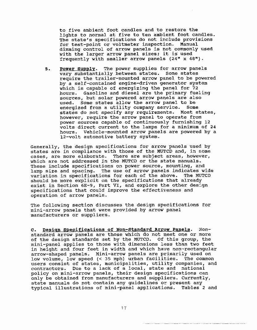
to five ambient foot candles arid to restore thelights to normal. at five to ten ambient foot candles.The state’s specifications do not include provisj.onsfor test-point c>rvoltmeter inspectic)n. Manualdimming control of arrow panels is not commonly ~lsedwith the larger arrow panel sizes; it. is”usedfrequently with smaller arrow panels (24” x 48”).
5. Power SuvDly. :Phe power supplies for arrow panelsvary substantially between stal:es. Some statesrewire the trailer-mounted ar]row panel to be poweredby a self-contained engine-driven generator syst(zmwhich is capable of energizing the panel for 72hours. Gasoline and diesel arcs the l>rimary fuelingsources, but solar powered arr~w panels are alsoused. Some states allow tbe arrow panel to beenergized from a utility company ser$ice. Somestates do not s:pecify any re~irements. Most states,however, rewire the arrow panel to operate frompower sources capable of continuously furnishing 12volts direct current to the lamps for a minimum of 24hours. Vehicle-mounted arrow panels are powered by a12-volt automotive battery system.
Generally, the design specifications for arrow panels used. bystates are in compliance with those of the ~TCD and, in somecases, are more elaborate.. There are subject areas, however,which are not addressed in the NTCD or the state manuals.These include specifications on power sc,urce, mounting, andlamp size and spacing. The use of arrow panels indicates widevariation in specificatic)ns for each of the above. The ~JTCDshould be more explicit on the specifications that alreadyexist in Section 6E-9, Pzlrt VI, and explore the other designspecifications that could improve the effectiveness andoperation of arrow panels.
The following section discusses the deSfLgn specifications formini-arrow panels that were provided by arrow panelmanufacturers or suppliers.
c. Desiun SPecification:3 of Non-Standard Arrow Panels. lVon-standard arrow panels ar~? those which do not meet one or moreof the design standards !set by the ~TCD. Of this group, themini-panel applies to those with dimensions less than two feetin height and four feet in width and which have non-rectangulararrow-shaped panels. Mini-arrow panels are primarily used onlow volume, low speed (< 35 mph) urban facilities. The commonusers consist of states, municipalities, utility companies, andcontractors. Due to a lack of a local, state and nationalpolicy on mini-arrow panels, their design specifications canonly be obtained from manufacturers and suppliers. Currently,state manuals do not contain any guidelines or present anytypical illustrations of mini-panel applications. Tables 2 and
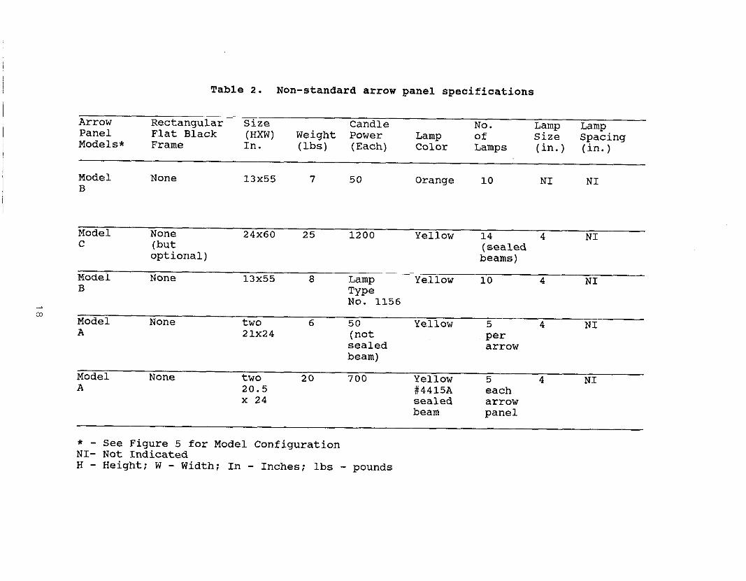
Table 2. Non-standard arrow panel specifications
Arrow Rectangular Size CandlePanel
No. Lamp LampFlat Black (HXW) Weight Power
Models *Lamp of Size
Frame In. (lbs)Spacing
(Each) Color Lamps (in.) (in.)
Model None 13X55 7 50 OrangeB
10 NI NI
Model None 24x60 25c
1200 Yellow 14 4(but
NI(sealed
optional) beams )
Model None 13X55 8 LampB
Yellow 10 4 NITypeNo. 1156
mModel None two 6 50 YellowA
5 4 NI21x24 (not per
sealed arrowbeam)
Model None two 20A
700 Yellow 5 420.5
NI#4415A each
X 24 sealed arrowbeam panel
* - see Figure5 for Model configurationNI- Not IndicatedH - Height; W - Width; In - Inches; lbs - pounds

Table 3. Non-standard arrow panel specifications (Table 2 continued)
SpeedArrow Restri-Panel Power Sun ction Dimm.
Models supply Shades (mph) Cap. Mounting Operation
Model B 20 amps fused None NI None Vehicle- Left, right,
circuit, automotive mounted left & right,
12 volt syetem center bar
Model C Standard 12 up to 9 ft. above Se~ential
volt battery (360 55 mph 50 per- pavement; directionaldeg. ) cent vehicle- modes left,
~im~ny. ~,o.tir,~e~ right cr inoperated both directionsmanually 4-corner
caution mode
Model B 12 volt; fuee None NI None Vehicle- Right, left;
aprotected mounted; double arrow;
magnetic & caution baror gutter~lOurlt~
Model A 12 volts: 11 amps NI Rear of Left: right:
at full load 1 in. NO or vehicle double arrowsun specs. roofshield(360 deg.)
Model A 12 volt: NI Vehicle top Left; right:(360 Manual right & left:deg. switch and flashing
bar
NI - Not Indicated

3 present a summary of non-standard arrow panel specificationsobtained directly from manufacturers. Figure 5 illustratesdifferences between the standard 24-inch x 48-inch arrow paneland non-standard arrow panels with respect to shape, dimension,and lamp configuration.
Nominal sizes of non-standara arrow panels are 13 x 55 inches,24 x 60 inches, 20.5 x 48 inches, and 21 x 48 inches. Thesepanels are constructed of either aluminum with a black bakeaenamel finish or flat black epoxy powaer-coated aluminum. Noneof the mini-arrow panels described here is rectangular, ofsolid construction, and finishes with non-reflective flatblack. The weight of the mini-arrow panel varies between 6 and25 pounds.
The lamp configuration on the mini-arrow panels are relativelythe same. The lamp size is four inches and emits a yellow colorexclusively. Spacing detail between lamps is lacking. Thenumber of lamps per mini-arrow panel is ten or more. The 24-inch x 60-inch non-standard arrow panel has 14 lamps due to itslarger panel area. The Model A (Figure 5) is comprised of twoseparate panels with five lamps in each. The total canalepower varies substantially among non-standard panels; Model Bhas a canale power of 1000 in comparison to 17,000 for Model C.
The mini-arrow panel is usually mounted on the vehicle top orat the rear. The mounting height to the base of the panelvaries between five and nine feet above ground. Greaterheights could be obtainea, however, by providing highermounting brackets.
The control operation of the mini–arrow panels also variessignificantly. Moael c, for example, has the capability toflash at 60 flashes per minute while one brana of Moael A has amaximum of 35 flashes per minute. Similarly, Model C has a 50percent dimming capability, while Moael B does not have adimming feature. Dimming of the mini-panel, when available, iscontrolled manually. Sun shades are provided for a few of themini-arrow panels.
The power supply of the mini-arrow panel is provided by astandard 12-volt battery.
D. Crashworthiness of Arrow Panels. The arrow panel is avulnerable object because of its placement in the cone taper orat the rear of vehicles during mobile operations. Highwayagencies are very concerned about the fre~ency of vehiclecollisions with shaaow vehicles e~ipped with arrow panels.Many agencies eguip the shaaow vehicles with truck-mountedcrash attenuators. For stationary operations, the arrow panelis commonly uses at the beginning of the taper. Although thereis strong evidence of the effectiveness of arrow panels inreducing the number of vehicles in the closed lane, the
20

~TCD standadtwe A arrowpanelNon–stand=damow Panel
ModelA
w~ @+
Size(tithes) 201/2X 24
Size( tithes) 24 X 48
NOn–stadwd arrowpanel Non-~mdard wow p~el
ModelBMOdd C
C~3 G~o~
Size( aches ) 1s x 55 Size(~ches ) 24 X 60
Figure 5. Configwation of standard and non–standard arrow panels.

potential for vehicle collisions with arrow panels and fire isnot beyond expectation, especially since many trailer-mountedarrow panels are fueled with gasoline. Past research did notaddress the ‘#crashworthinessvs of arrow panels.
22

111. APPLICATIONS IN PN\CTICE
Standard arrow panels are generally used for stationary ormoving-maintenance operations when a lane is closed. Arrowpanels are also used in traffic splits ar,d diversions (laneshifting) when construction and maintenar[ce activities areconducted in the roadway.
part VI of the ~TCD (~), presents gener~ll guidelines on theuse of the arrow panel as an optional trzlffic control device.Today, however, the state--of-the-practice of arrow panelsdiffers from that in the ~TCD. Table 4 demonstrates arrowpanel applications as observed in a s@lection of state trafficcontrol manuals. As it shows, the arrow panel is beingutilized for almost all sYLngle and multiple lane closures aswell as for partial roadway closures on dividecl and undividedfreeways and local streets.
The cost of standard arro~r panels range from $750 to $5,000depending on size and acc~?ssories. Mini-arrow panels can bebought for less than $250. Without rega]rd for effectiveness,the relatively higher cost (acquisition and maTLntenance) aladthe cumbersome transport @>f large arrow ]?anels have forced manymunicipalities and counties to consider !non-standard and losslabor-intensive mini-arrow panels. Gener~ally, the mini-pan,slsthat are currently used do not meet the :size and shapespecifications of the Type A arrow panel (24 inches x 48inches) in the ~TCD. Nevertheless, their use and applicationhas spread widely, especially on city streets.
The following sections discuss the current use of standard andnon-standard arrow panels as prescribed in the state manuals ofDelaware, California, Illinois, Maryland, Pennsylvania, Ohio,Minnesota, Michigan, New York, Virginia, and the District ofColumbia. Excerpts from state manuals and photographicillustrations of field applications are used to demonstrate thestandard and non-standard arrow panel applications for singleand multi-lane closures and for moving operations when a laneis closed.
A. MWCD Rem irements. The application. of the arrow panel, asspecified in the ~TCD and the Traffic Control Devices Handbook(TCDH) supplement, is relatively vague. The TCDH is intendedto supplement the ~TCD Ely interpreting and linking the ~TCD’snational standards with the activities related to complyir~gwith those standards. Although the ~TCD offers generalguidelines for arrow panc!l use, it lacks adeq.ate illustrationsand specifications for arrow panel applications.
23

Table 4. Use of arrow panels in work zones
Lane Closure Multi-Lane Closure Movinq OwerationLeft & Right & Diver-
State Left Riqht Center Center Center Left Center Riqht Shoulder sion
Maryland * *
* *
* *
* *
(**)
*
*u
(**)
(**)
*
(**)
(**)
(**)
*
(**)
(**)
* NI *
* (**) *
* * *
* NI *
@
**
*
**
*
**
**
*
New York
Ohio
Pennsylvania(optional)
Illinois
: (optional)* * NI * * * * * ** *
California(optional)
* * (**) (**) (**) NI NI NI ** *
Delaware * *
* *
* *
(**)
(**)
NI
NI
(**)
(**)
NI
(**)
(**)
* NI *
* NI *
* NI *
NI
@
@
NI
**
*
Virqinia
Michiqan
* - denotes sinqle arrow panel for sinqle lane closure- denotes no use
(::) - denotes two arrow panels; one panel for each lane closureu - urban work zones
NI - not indicated@ - denotes sinqle arrow panel for shoulder work

The ~TCD implies that tkle arrow panel ~hoUld be used fOr lane
closures, diversions, an~~ traffic sPlit~. The ~TCD isspecific, however, on conditions where arrow panels should notbe used. Arrow panels sklould not be used where lane clOsuresare not rewired, for work on or outside the should$r that hasno interference with adjacent through lanes, ?Lnd on two-lane,two-way roadways that are controlled by flagmen. The cautionmode (fOur or more lamps,, arranged in a pattern which wil:l not
indicate a direction) apl>lication is also suggested by theWTCD for stationary or moving work opelcations on or outside ofthe shoulder (1). The mJTCD guidelines appear to have be{~n agood starting point from which states a]?d local jurisdictionshave adapted and subse~~?ntly advanced ‘this Practice.
B. current Use of Standard Arrow panels. This sectiondiscusses the application of standard arrow panels forstationary and moving-maintenance lane closures, dlverslOns,and shoulders.
1. Left and right lane closures. In Cne majority of thestates that were evaluated, arrow panelS are almOstalways used when left and right lanes are c+osed formaintenance or construction on state maintainedhighways. This practice exists even though thestates’ ~TCDs indicate that the arrow panel isoptional. Figures 6 and 7 are schematics from theMichigan and Maryland MUTCDS that illustrate the useof arrow panels for right and left lane closures ondivided and undivided highways (H, ~). Figures 6and 7 illustrate how the arrow panels a,re placedbehind the cha.nnelizing devices and at the beginningof the taper. When shoulders are available, arrowpanels are often placed at tk,e beginning of the taPeron the shoulder. When shoulc~ers are not present,arrow panels a[re placed on tk~e lane. Figure 8 showsthe use of arrow panels for lane closures in Michiganand Pennsylvarlia. Based on c)bservations of severalwork sites in the states and local jurisdictionsvisited, it appears that the states are confomning tothe use of the ~TCD standard arro~~ panels (30 x 60inches or 48 >C 96 inches) for state maintainedhighways, particularly in high-density urbanfreeways.
Discussions w~Lth Officials frOm municipalitiesindicate that the arrow panel is very effective onarterials and local streets where the driver’sadvanced view of the work zo]~e is ]restricted. Urbanwork sites, h<>wever, present a unime challen9’=.Fre~ently, rl>ad geometries coupled with the roadconstruction ~>r maintenance ~activit=ies do not allowthe installation of the reguired minimum taper lengthor an ideal t:raffic control :setup. In many
25

A,Stiglerightlaneclosure, B. Singlerightlane clo-~, c, ~p~iona~~rrow ~ane~for
unditidedhighway,low speed ditidedhighway,low speed,
source (~ )rightlane closure.Source:(u ;
Source: ( 24 )—
J ! ‘ v . t
- 1 “1
I ! ‘ v -
500’ * 500, *
> I500’ *
: .,.
I 1$ [~\\
I E m
I r:– F-–e W1–6
1% ‘
orUghtedhow Pa
I I‘::,~~ ,::;L ............I – - I --
i1
I “- I - -7 i ~i
I I::. L50W * 500’* 500’*
50V * 500,* 500’*
50V* 500’* 500’*
!, V:v “ V:v, !. v! v
XG~ :
~ ~.,ti~ SrrOW p~~, . ~hame~a~ion deviCs ~ Work area
~ Directionof traffic * si~ L Lengthof tapsr
Figure 6. Application of the arrow panel in typical right lane closures

>
—,.
—..
-m,..
_—
—
—c=
–..
..
..
/
444
27

(a) Michigan
(b) Pennsylvania
Figure 8. Placement of the arrow panel for typical right laneclosures in Michigan and Pennsylvania
28

2.
situations, the taper must be made sh!orter thanminimum re~irements, or in some cases is notinstalled. Observed practice, in these situations,is the use of lz!rge trailer-mounted zkrrow panels toinsure longer effective visibility to the work area.Photographs shown in Figure 9 are representative oftypical urban a~rterial work sites.
The use of a su~>plementary arrow panel (a secondarrow panel located on the shoulder upstream of thelane closure) to increase the effect:Lve sightdistance for a right- or left-side freeway laneclosure when the sight distance to the work area isrestricted (les!s than 1500 feet) was not observed inany of the states visited. Most of the sitesvisited, however, had ade~ate site distance to thework area and did not reguire supplemental arrowpanels. The state officials interviewed concurredwith the recommendations of Faulkner and Dudek (5)and recognized the value of a supplemental arrowpanel when the sight distance to the work area isrestricted. They also recognize, as Faulkner andDudek caution, that the supplemental arrow panelshould not be placed too far upstream from the workarea. Illinois, for example, supports the use of asupplementary arrow panel if deemed necessary byfield measurements of sight distances.
Center lane clesupes. Maintenance work in themedian lane or shoulder lane c,f a six-lane divicledhighway is generally accommodated by the closure of asingle lane. Closure of either of these exteriorlanes is relatively easy to ac!hieve and, compared tomore extensive traffic control re~irements (i.e.,detours, crossc,vers, and multi-lane closures) , thisapproach has a minimal effect on traffic operations.
The multi-lane closure strategies illustrated ix]Figure 10 are commonly used to accommodate work inthe middle lane. The multi-lane closure strategyinvolves closing an exterior lane and one or mo]?eadjacent middle lanes. Th@ major disadvantage of themulti-lane closure strategy presented in Figure 10 isthe resulting ILoss of highway capacity. Fieldstudies conducl:ed by Dudek and Richards (Q)indicated that an average of only lILOO vehicles perhour can be accommodated on the one available oloenlane. On high-volume highways, this would result inconsiderable t]caffic congestion and delay. In recentyears, highway agencies have l~sed the traffic controlstrategies ShOT(n in Figures 11A and llB as a means ofconducting maintenance on the middle lane andaccommodating traffic. This approach was firstreported by Rifzhards and Dudek (~) and was found to
29

Figure 9. Application of the arrow panel in lane closures onlocal streets
30

u
A, Centerlaneclosure:six–tie~ded, rmal. B. Centerlaneclosureshortdurationwork.
Somce ( 24 ) Sowce: ( 25 )
‘!& i ‘[~
; ~i F 21 !E”
~GEND :~ mastig mrow pmel . Ch-elizationdevice ~ Work area
Dkectionoftitic Sifl L Lengthoftaper
Mgme 10. &row panelapphcationsh mdti–laneclosures

A,Centerlme closure:udtvided B, Centerlaneclosure:dtvidedhighway,c. centerlane~lo-e:highway,low speed. wbm and rutiSomoe: (~ )
wbm ditidedMghwaySource( 23 ) SOuce ( 23 )—
4 ‘1 ;: ‘ ~ ; ,:‘ , : 7:
fl~ ~fl -250Q * ~] ‘I500,+
.:-
?!
:;~] 1
500,i
vj~]v :Nv~v;:.:::.-: :..!,.,...., :::.‘.’-/”r--L ~ =1 L
......-.:. L
~2L
[
1000’.“ 1680’
,... L.“
500 * IV’v: II“ ,~oo1 1680’
Vvv500 +
“ Vvv‘-’500* “ ‘‘:-. ...... 2600’
Vlvlv. Vlvlv~GE~ :
~ mashi~ arrowpanel m Cha~ehzationdevice ~ Work ....Sign
Dhectionoftrtific L Lengthoftaper
Figure 11. &row panel applications in center lane closures on urban and rural roadways
be very effecti%’e. It was estimated that trafficvolumes up to 3c}o0 vehicles per hour could beaccommodated. ~!he major advantage of the traffic:control strategies shown in Figures 11A and llB !LSthat they minimize driver confusion by closing onelane and then ,Ifunnelingtt drivers to the left and
right side of t?~e work area. Drivers are notrewired to make a choice (left side or right side)because the traffic ,,funnelwvpositively directs
drivers to the proper path. In contrast, the trafficcontrol strategj7 shown in Figure llC rewires driversin the middle lane to make a choice and can thereforebe very confusing. The traffic contrc>l strategy shownin Figure llC is not widely supported or used. Itsuse is limited to exceptional cases and at low-s]?eed(35 m.p.h., or :Less) urban facilities.
Figures 10A, 11A and IIB illusi~rate the use ofmultiple arrow ])anels. Based on discussions witlnstate and city highway officials, the use of twoarrow panels folc middle lane closures on six-lan,edivided rural highways is becoming the preferredpractice in the states surveyed.
Concerned about the need to ensure positive guidancewhen multiple a:rrow panels are used in center laneclosures, the Ftederal Highway Administration iscontemplating r,?vising Figure 6-17 of the TCDH.Preliminary ideas for the revision a:re indicated inFigure 12. Not= the use of one arrow panel insteadof two and a li:ne of barrels leading into the taperthat closes the center lane.
3. Multi-lane closures. Multi-lane closures aresituations which involve closing eit~her the left orright lanes and one or more adjacent middle lanes ondivided highways having six or more lanes. The ~TCDsuggests the use of one arrow panel for multi-laneclosures (L) . However, most of the states visitedare currently using multi-panels: one panel fOr eachlane closed. The state-of-practice in the statesvisited regarding multi-arrow panel use is to placethe first panel on the shoulder at the beginning ofthe taper and the second panel at the beginning ofthe second taper behind the channelizing devices.The spacing between the two arrow panels is generallyegual to the length of three tapers. Figure 13illustrates a typical multi–lane closure where singleor multiple arrow panels are being used.
Although state manuals may still show a single arrowpanel for multi-lane closures, the majority of thestates visited now support the use of two arrow
33

B5
g!=“
@ ~@@
i
\
L L— i Ii 4
1m~mnamm! I “~”~x- — —
—,s s,, T,~,n~,7 — z,,, ,
# 4~,,,,, , 18, ,
4
L
+
II i
n
EL
~~ N.te“ 1.Ad&ti.naladvance~ may be necessaq.
2.A btierqacemay ~e used3.L = lengthoftaper,referh Tabel6-3.4.Metticconvetion.500ft.= 150m.
Pavementmarbgs thatshotid~ r~oved fora
2L@ L ~g;
long-termproject.Temporv m-s tibeplacedasneeded,
Figwe 6–1? TCDH.ReferenceNo. 10
WGEND :Temporarymartigs . ChameUzationdevice
~ Work area
* Sign L LengthoftaperDirectionoftrtific x AdditionalBarrels
Figure 12. Proposed TCDH revisionfor use of one arrow panelin center lane closure.

A.Mdti–lme closures,dividedhighway B. Multi–1aneclosures,longduration. C. Multi-1anecloswes.
SoWce: ( 24 ) Somce ( 25 ) SOwce: ( 19 )
‘ v~p : yd - ,~~
“N ~ \, ;;;~T .
nv 1:1
I I i- 500’ 2 L :..... i 1~1%-. -. ..-. ........ ~.1 “. ~.2000’
800’ m.
:m:IL
o :. ......
1000’ %
0:
“-
700’ 0 : ~ 2001
D “...~......
;m:
n -Vvv]00 : :Vlvlvlv:LSG~D :
B mastig arrowpanel . ChameMzationdetice ~ Work =..
+ Dkectionof traffic & Sign L Lengthoftaper
Figure i3. AppiicatiOn of arrow paneis in muiti–iane ciosures.

panels as illustrated in Figure 13A. In conditionswhere the desirable spacing between the two panelscannot be met, such as in urban areas, a minimum of1000-1500 feet spacing between the two panels isusually recommended. The reason for this minimumspacing criterion is that approaching motorists willbe less confused if they are allowed to view only onepanel display at a time. Thus , a spacing of 1000-1500 has been recommended by practitioners as theminimum spacing between two panels.
4. Movinq maintenance lane closure operations. Movingmaintenance operations where a lane is closed onurban roads or freeways are conducted at speeds lessthan 25 miles per hour. Common moving maintenanceactivities include pavement milling and resurfacing,sweeping, pavement striping, median or shouldermaintenance, and grass spraying and mowing. Formobile operations, the ~TCD suggests the arrow panelbe placed at the rear of the activity in the closedlane on a vehicle separate from the maintenancevehicle itself. The ~TCD does not distinguishbetween urban and rural operations.
The majority of the states visited followed ~TCDrecommendations. States will either have arrowpanels mounted on the back of maintenance vehicles orwill use trailer-mounted arrow panels that are pulledbehind the maintenance vehicle. Figure 14illustrates the use of trailer-mounted arrow panelsfor right lane closures. Schematics for movingmaintenance operations for the states of Delaware,Illinois and New York are shown in Figures 15 through17. As noted, all three states specify the use of atleast one arrow panel. This is also specified in themanuals of the other states. surveyed.
A flashing arrow or sequential chevron arrow panel isnot appropriate for lane closures on two-lane, twO-way roadways. An arrow flashing to the left givesdrivers the false indication that it is safe toproceed to the left side of the maintenance vehicleinto the lane of opposing traffic. Therefore, when alane is closed on a two-lane, two-way roadway, thearrow panel is placed in the caution mode. Figure17B illustrates the use of a four-corner flashingcaution mode used in the State of New York.
5. Shoulder cloeure. Shoulder activities includeshoulder reconstruction, maintenance, trash removal,sweeping, grass spraying and mowing, and slopetreatment. In the majority of cases, conventional
36

Figure 14. Moving-maintenance lane closure on urban arterials
37

—=-E-:
m-
-E-
‘m-
——
——
——
——
——
ti4
3a

I
~GEND : ~ Work mea
~ mastig arrowpanel - Ch.melizationdetice % Flagger
* Dtiectionoftraffic * Sign ~ Trail~ehi.le
Figure 16. Application of the arrow pane~ in moving operation for
single and multi–lane closures.

A. Motig pavementmarktngoperation
on one–way,multi–laneroadways.Souce (~ )
B
n
B. Motig pavementmar- operation,>on two–way,two–laneroadways.Source(~ )
. ChameHzationdefice
Figure 17. Applicationof the arrow panel for moving operations,

advance warnirlg signs are ade~ate to alert motoristsof work ahead. However, the arrow panel has becomethe preferred traffic control. device especialllr formoving mainterlance operations.
There seems to be unanimous agreement that a flashingarrow or sequential chevron should not be used forshoulder closllres (unless the shoulder lane is closedor encroached by the work vehicles on dividedhighway). Al:l eight states visited use the calltionmode when arr<>w panels are used during shoulder work.Maryland, New York, and Dela~#are use the caution fourcorner flashing mode: whereas, Pennsylvania an~iVirginia only specify the cal~tion ~Flashing bar mode.
There is concern on the part of some researchers andhighway agencies that the caution :Elashing bar m?Y beinterpreted by drivers as a :malfunctioning flashlngarrow resulting in unnecessary lane changes.Consequently, some agencies ‘prefer the four-cornerflashing mode for caution displays.
Figure 18 shows photographs of the caution flashingbar mode during a shoulder closure. Figure 19illustrates traffic control during shoulder closuresin Ohio.
6. Lane diversions. Lane diversions frequently occurwith partial roadway closures (e.g., lane shifts) orcomplete roa~way closures (e.g. , crossovers) . Men alane is closed in a crossover traffic strategy, it isuseful to use a flashing arrow for the lane closure.Officials in eight states offer a mixture of cbpinionsabout the use of the flashir~g arrow panel in theflashing arrc,w or se~ential chevron modes for lanediversion whe!n a lane is not. closed. Although thesemodes are used extensively, some c,fficials arque thatsuch applications are unsafe and weaken thecredibility c)f the arrow panel because the flashingarrow and sec~ential chevron are perceived by driversas lane clostare rather than lane diversioninformation. This driver misunderstanding was foundin laborator~r studies conducted blr Graham et al. (Z) .Some official-s further believe that arrow panelsshould not be used routinel>l for lane diversions, andlthat their drawbacks should be studied prior I:ocontinued use.
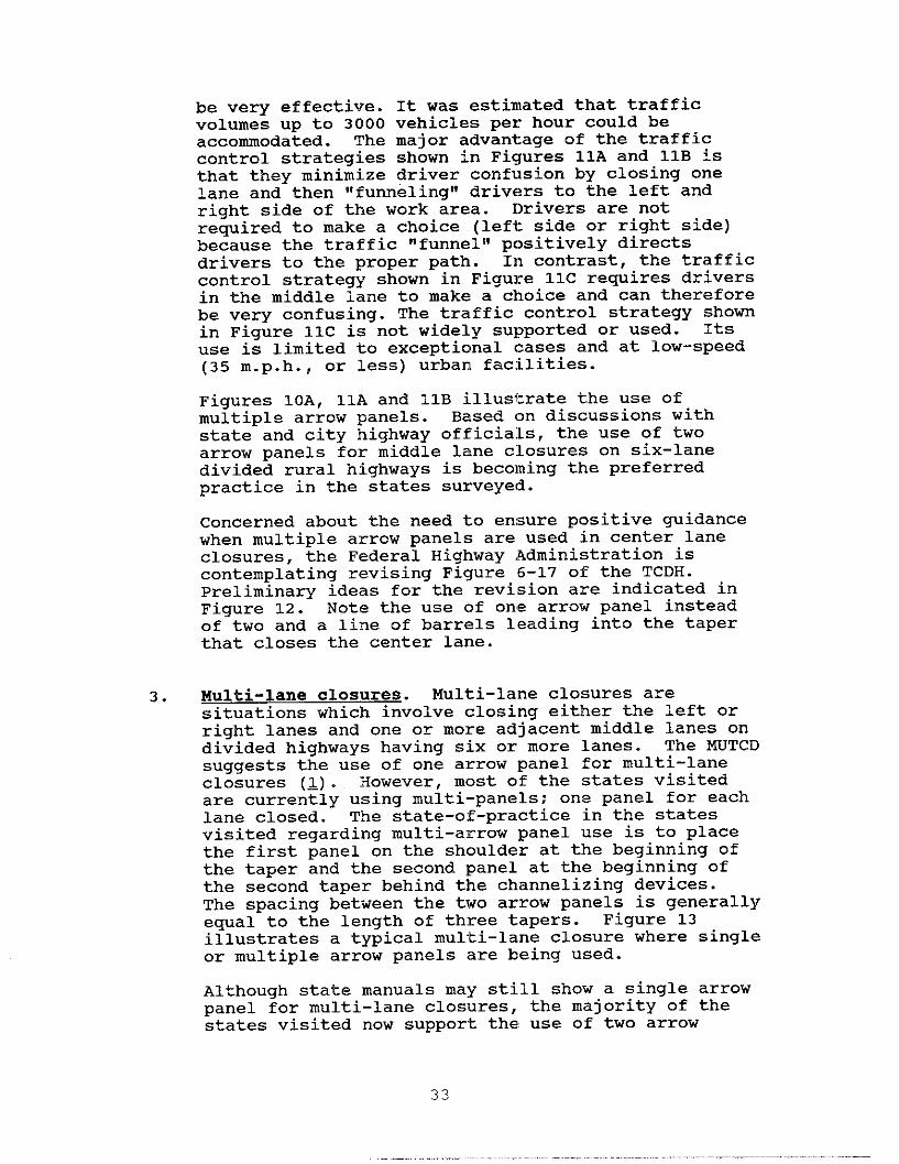
Figure 20 demonstrates crossover traffic Cont:rolstrategies in Maryland usin(~ arrow panels when a lan~!closure is included. Figure 21 illustrates tile arrowpanel placemt?nt for crossovers involving a lameclosure. Fi[Jure 22 illustrates a situation where the:
41

Figure 18. Application of the caution bar mode for shoulderclosure
42

A.Motig-mtiten-ce activi~eson B. Movhg–matitenanceoperationon
two-lane,two–wayroadways shotidertithl-e encroachmentonSowce ( 23 )— two–lane,one-way roadways
SOwca ( 23 )
o v~ </Work ties
; ; I ‘
./”<, w~=k ~~a
“[ “ :
m
50W 5 ~astig Or Sequential
to
~ Id~ tiow Panel
100W 1:Back–Up Vehicle
F
01v V!vEGE~ :
~ flastingarrow panel m .ham.fizationdevio. ~ Work area
~ Dkectionof traffic ~ Sign +, Flashers
Figure 19. Trafficcontrol for shoulder closure

Figure 20. Application of the arrow panel in crossovers
44
n
..
...
I
N“
45

—
~’—— —=>—
~——— —->
——
~GE~ :— Concretebarrier m Chamefizationdevice ~ Work area
& Sign- Dkectionoftrtific L Lengthoftaper
Figure 22. Lane shifttithout lane closure and arrow panel.

alignment of a:Ll lanes is slightly shifted andtraffic is controlled ~ithout arrow panels.
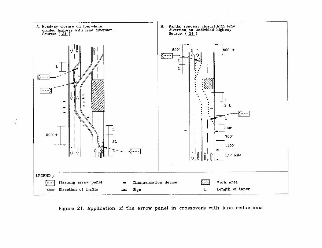
7. Traffic splits. Standard, large traffic-splitwarning signs (W12-1) have been used behind laneclosure barricades to warn drivers of the lane splitcondition. Recently, the arrow panel with a doublearrow flashing mode has been used to suppleme~t thesign and provide advance notice of the split. Mostof the highway officials intewiewed believe that theflashing double arrow display demands driverconcentration and tends to cause confusion. Figure23 is a schematic from Maryland of an arrow panelapplication in a traffic split incorporating theshoulder as a temporary lane.
c. Summarv of Current Practices. By and large, the currentpractices observed in California, Illinois, Maryland, Michigan,New York, District of Columbia, Pennsylvania, and Virginiaoffer some useful information on the application of arrowpanels, especially for stationary and mobile ILane closuresituations. The salient observations are summarized below.
1.
2.
3.
4.
5.
6.
7.
State and local highway officials agree unanimol~slythat the arrow panel is a very effective trafficcontrol device in promoting earlier merging into theopen lane and in diverting, and controlling trafficaround construction and maintenance activities beingconducted on or adjacent to the traveled roadway.
The arrow panel is immensely popular and is currentlywidely used in rural and urban work sites.
The arrow panel is widely used at long-term left orright lane closures on all facilities other than two-lane, two-way roadways.
Some states use supplemental arrow panels (a secondarrow panel) for lane closures with restricted sightdistances (less than 1,500 feet) on high-speedhighways.
Use of arrow panels for middle lane closures variesamong the states.
Multi-arrow panels are used for multi-lane closures.
Arrow panels are used by all the states for movingmaintenance operations. The states use both singleand multi-arrow panels. The number of arrow panelsvaries among states.
4?
Figme 23. Application of the arrow panel in typical trafficsplit,

8. For shoulder closures and for lane closures on two-lane, two-way roadways, the caution mode of operationis used. The four-corner flash%ng panel appears tobe the preferred choice of most states.
9. Lane diversions and traffic splits are specialconditions for arrow panel appl:Lcations. Stateofficials indicate that the arrow panel in thesecases demands more of drivers. Most states havedeveloped typicalL drawings that illustrate arrowpanel applications.
10. The 48-inch x 96-inch arrow panel is the most popularof the three standard panels, even in urban workzones. The 30-inch x 60-inch arrow panel wasobserved only for mobile operations on moderate speed(45 miles per hour). The base mounting height of thetrailer-mounted and truck-mounted arrow panels wasapproximately 7 to 8 feet.
11. Based on discussions with several state highwayofficials, there appears to be interest in specifyinghighway speed ranges for each s<zandard arrow panel.A few states have already defined these ranges.
D. Current Wee of Non-standard Arrow Panels. The ~TCDspecifically rewires all arrow panels to be rectangular, ofsolid construction, finished with non-reflective flat black,and meet the minimum size requirement in accordance with speedand type of facility. Any arrow panel which does not meet oneor more of the ~TCD standards is considered to be non-standard. Due to their cost and transportation advantage, lnon-standard arrow panels have now become as popular on localstreets as the large panels are on freeways. The followingsections discuss the current practices of states,municipalities, and utility companies in using non-standardarrow panels.
1. State governments. The non-standard panels areregarded as illegal traffic control devices when usedon state roads. Profileration of these devicesappears to be under control in some states, e.g. ,California and Pennsylvania. The non-standard arrowpanel has been observed on several state-ownedvehicles, and its existence cannot be ignored. Inmost cases, these panels lack a rectangular non-reflective flat lolack background, have less panellamps than the minimum re~irement, do not have theminimum legibility distance, and are small in size.Figure 24 demonstrates a non-standard arrow panelwhich possess at least three of the abovedeficiencies: size, flat black finish, andlegibility dista]nce. Although state officials
49

Figure 24. Non-standard arrow panel on an Interstate highway
50

discourage the use of non-standard arrow panels onhigh-speed roads, there are several non-standardarrow panels that are mounted on state vehicles. Infact, discussions with arrow panel suppliers indicatethat at least seven state highway agencies arecurrently using the non–standard arrow panel size of24 inches x 60 inches on moderate to high–speed (45-55 miles per hour) roadways. Among the applicationsobserved for the non-standard arrow panel areshoulder maintenance, setting up channelizingdevices, interchange sweeping, highway littercontrol, and mobile operations. Cost savings andmobility in work zones appear to be the primaryreasons for acquiring non-standard arrow panels.
2. Nunicivalitie5. Local governments are heavy users ofthe mini-arrow panel. The mini-arrow panel offersthem cost advantages, less labor–intensive operation,accessibility, flexibility, and a traffic controldevice that is capable of displaying the same modesas some larger standard arrow panels.
The mini–arrow panel was observed mostly on lowvolume, low speed roads. The mini-arrow panels weremounted above the cab or at the rear of vehicles.Mounting height ranged from five to ten feet.Figures 25 and 26 demonstrate a few fieldapplications. The City of Bzltimore, Maryland, ownsseveral mini-arrow panels which are used duringlitter control and pavement marking operations. TheCity of Monroe, Michigan uses mini-arrow panels tomanage traffic during crosswalk pavement markirigoperations. The users of the mini–panel in urbanareas are utility companies, city trafficdepartments, city maintenance departments, andcontractors.
Proliferation of the mini-arrow panel among citygovernments is not under control by any means.Cities, contractors, and utility companies arewillingly purchasing these devices. Proliferation isgreater among cities which do not have an activeprocess for the review and approval of all trafficcontrol devices for work zones. In such cities it isnot uncommon for maintenance personnel to order anumber of traffic control devices, including non-standard arrow panels, without notifying the trafficengineering division. In at least three largecities, Chicago, Washington, D.C., and New York, thetraffic engineering officials were not aware of theextensive use of non-standard arrow panels on localstreets. San Francisco, California., is one city thathas not allowed non–standard arrow panels to emerge
51

Figure 25. Use of mini–arrow panels on local streets
52

Figure 26. Use of mini-arrow panels on local streets

as de facto traffic control devices. Unlike mostcities, San Francisco maintains a rigid policy whichrequires all traffic control devices for work zonesto be approved by the traffic engineering divisionand provides for strict enforcement from the policeand a team of trained field inspectors.
3. Utility companies. Over the past ten years, theutility companies experience with the mini-arrowpanel has changed dramatically. According to a studyby Graham et al. (z) in 1978, utility companies didnot use arrow panels to conduct their operations.Today, utility companies are acquiring a great numberof mini–arrow panels to conduct their dailyoperations.
The Washington Suburban Sanitary Commission (WSSC) isa heavy user of mini-panels and has acquired at leastthree brands of mini-arrow panels. Mini-arrow panelsnow are being used for emergency, short-duration, andlong–duration operations when a lane is closed.Observed mini-arrow panel applications by utilitycompanies include water and sanitary structureadjustments and replacements, structure cleaning, andtelephone line repair. Few mini-arrow panels wereobserved on moderate to high-speed arterials.
Due to the lack of local, state and federal policieson the use of the mini-arrow panel, its use hasspread to moderate speed (25 – 45 miles per hour)facilities. A mini-arrow panel has been observed inoperation on the same construction vehicles asflashing strobe lights. Such use is not yet definedby any of the users, but it is speculated that themini-arrow panel is usually mounted on trucks thatalready have the strobe lights. It is not knownwhether the strobe lights are operated together withthe mini-arrow panel.
State and local officials expressed mixed opinionsabout the mini-arrow panel. The majority of theofficials agree that the mini–arrow panel should bestandardized in terms of size, readable distance,lamp characteristics, and application requirements.Few officials, however, insist that the ~TCD’ssmallest standard arrow panel (24 inches x 48 inches)be used in lieu of the mini-panel. The ~TCD’ssmallest panel can be mounted on the top or rear ofvehicles, is capable of displaying equal or greatermodes of operation, has dimming and flashingcapability, and is the same size or slightly largerthan most non-standard arrow panels. Yet, thepractice in urban jurisdictions is overwhelmingly
54

supportive of the mini-panel.
The following summarizes key obsewations about non–standard arrow-panel practices:
a.
b.
c.
d.
e.
f.
9.
h.
i.
j.
The non-standard arrow panel is generally notallowed in work zones on “interstate highways.Profileration at the state levels appears to beunder control.
The 24-inch x 60-inch non-standard arrow panelis currently used by state maintenance forces onmoderate to high-speed state roads, includinginterstate facilities.
State highway officials support the need formini-arrow panels among local agencies.
The use of non-standard arrow panels among localgovernments is extensive and is stronglysupported by urban officials.
Specifications for the design of non-standardarrow panels are lacking.
Apathy within the urban traffic engineeringcommunity has encouraged the proliferation ofnon-standard arrow panels.
The non-standard arrow panels appear to beeffective in some situations. Applicationguidelines could curb their inappropriate usage.
The mini-arrow panel is currently used onfacilities with posted speeds up to 45 miles perhour.
Among the applications for mini-arrow panels arepavement striping, pavement resurfacing, signalmaintenance, litter control, and utility work.
Mini-arrow panels are widely used by utilitycompanies,.
55

IV. =INTENANCE AND COST OF ARROW PANELS
The maintenance and cost of arrow panels are essential to theirselection and application. mile standard trailer and roof-mounted arrow panels can be used to control traffic in highwaywork zones, their high cost is the primary reason why utilitycompanies and maintenance divisions of local governments havesought inexpensive devices such as the mini-arrow panel.
This section discusses some of the most common maintenanceproblems that were observed during the field visits andpresents the cost of ac~iring and maintaining arrow panels.
A. Maintenance. Maintenance of arrow panels varies by panelsize, mounting eguipment, ~ality of lamps, dimming features,power supply, and placement. For example, trailer-mountedarrow panels reguire more maintenance than truck-mountedpanels.
Two common problems that result from a lack of propermaintenance are inadequate dimmer control and non-uniformity inthe brightness of panel lamps. Inade~ate dimming of theflashing arrow panel at night was observed at several worksites. Similarly, several state highway officials emphasizedthis problem and indicated a need for better dimming controlfeatures. One state official indicated that of the twentypanels inspected during night operation in his state, more thanhalf of these panels did not meet the state’s dimmingre~irements although all the panels were designed to meet the~TCD’s or the state’s criterion on dimming control.
Excessive brightness of the arrow panel can blank out the laneclosure features and cause temporarily ‘blindness to motorists.This is perceived to be a very serious problem despite the lackof accident or conflict data to guantify the seriousness andimplications of this problem. State officials indicated thatsuch problems are usually corrected once they are detected, butthey strongly believe that the panels should be e~ipped withtesting mechanisms to detect these problems prior to usage andduring application. The current procedure is very inconvenientand time-consuming; it rewires visual inspection at night.Test-points or accommodations for a built-in voltage metermechanism is currently lacking. According to discussions witharrow panel vendors, these features could be easily designedand implemented. Arrow panels that are currently used couldalso be rewired to include these provisions. Some arrow panelvendors recognize these problems and agree that a continuingmaintenance effort is currently rewired to assure properoperation of the dimming control unit.
56

Another problem that was observed and discussed withcontractors is the proper installation of replaced lamps.Faulty installation usualLly causes disorientation of the lampsand non-uniformity in the panel lights. This problem wasnoticed during both day and night operations. In addition,photocells should always be cleaned, inspected for damage orflaws in the operating electronics, and checked for faceposition. The lamp hoods also should always be installedunless the lamps are recess-mounted.
B. Cost of Em inment. ,%s shown in Table 5, the cost ofstandard arrow panels varies according to the panel size andmounting type. The trailer-mounted arrow panel is the mostexpensive of the three types. The average cost of the trailer-mounted and vehicle-mounted (48-inch x 96-inch) arrow panel is$5,000 (including the cost of the trailer) and $1,800,respectively. Both types could be rented for an average costof $20 and $15 per day, respectively. ‘The trailer-mountedpanel is more expensive to maintain than the other types. Thecost of the standard 24-inch x 48-inch arrow panel rangesbetween $600 and $800: its upkeep cOst is approximately $lo Perevery 1000 hours.
The cost of mini-arrow panels depends on the sophistication andsize of the e~ipment. Due to the lack of uniformspecifications, the cost of the mini-panel ranges from $200 to$600.
57

Table 5. Cost of arrow panels
Dimension AverageType (Inches) cost
Standard Trailer-Mounted: 30 X 60 $4500
48 X 96 $5000 (@)
Standard Truck-Mounted: 24 X 48 $ 750
30 x 54 $150048 X 96 $1800
Non-StandardTruck-Mounted: 13 x 55 $ 21O-$6OO*
20.5 X 24 $ 265**21 X 24 $ 300**24 X 60 $ 595***
* Price excludes mounting e~ipment** Price includes roof-top mounting e~ipment
*** Price includes mounting e~ipment and solid state controle~ipment
(@) Includes the cost of the trailer
58

v. CONCLUSIONS
1.
2.
3.
4.
5.
6.
7.
8.
Past research clearly indicates that the flashing arrowpanel is effective in promoting the earlier merging oftraffic from the closed lane into the open lanes.
Section 6E-7, Part VI of the WTCD implies that the arrowpanel could be used as an optional device. The body ofresearch and practice by the states, however, suggest thatthe arrow panel is a prima~r device for lane closures.States are being more descriptive about situations inwhich arrow panels are specified.
State practices imply that the arrow panel is used at alllong-duration left and right lane closures on multi–lanedivided and undivided highways in urban and rural areas.
The need for supplemental arrow panels (a second arrowpanel on the shoulder upstream of the taper) in situationswhere the sight distance -- horizontal or vertical-- isless than 1500 feet is well supported by research (X) andstate practices.
Placement of the arrow panel on the shoulder immediatelybehind the channelizing devices appears to be the mostcommon and effective practice. Where the shoulder isnarrow or does not exist, the most effective placement ofthe arrow panel seems to be immediately behind thechannelizing devices at the beginning of the taper.
A base height of seven to eight feet from ground cover ispredominantly used on trailer-mounted and truck-mountedstandard arrow panels. State practices and past researchstrongly support this mounting height. Greater mountingheights are more expensive and not necessarily moreeffective.
Past research indicates that for lane closures theflashing arrow or the sequential chevron are preferredover the sequential arrow.
Past research did riot find any significant differencesbetween the flashing arrow and the sequential chevronmodes. State practices, however, indicate a strongerpreference for the flashing arrow mode.
.
9. Most states are using arrow panels during movingoperations.
10. state practices imply that a flashing arrow or se~entialchevron should not be used for shoulder closures unless
59

11.
however, support the use of the caution mode operationwhen the arrow panels are used for shoulder closures. Theuse of the caution four-corner flashing node appears to beon the rise. The caution flashing bar mode is stillwidely used, however.
Officials in eight states offer a mixture of opinions onthe use of the flashing arrow panel in the flashing arrowor se~ential chevron modes for lane diversion when a laneis not closed. Although these are modes used extensively,some officials argue that such applications are unsafe andweaken the credibility of the arrow panel because theflashing arrow and sequential chevron are perceived bydrivers as devices for lane closure rather than lanediversion. This driver misunderstanding was found inlaboratory studies conducted by Graham et al. (z). Someofficials further believe that arrow panels should not beused routinely for lane diversions, and that theirdrawbacks should be studied prior to continued use.
12. Standard, large traffic split warning signs (W12-1) havebeen used behind lane closure barricades to warn driversof the lane split condition. Recently, the arrow panelwith a double arrow flashing mode has been used tosupplement the sign and provide advance notice of thesplit. Most of the highway officials interviewed believethat the flashing double arrow display demands driverconcentration and tends to cause confusion.
13. Past research demonstrates a need for multi-arrow panelson multi-lane closures. State practices have also beenvery supportive of the multi-arrow panel application. Onearrow panel is used for each lane closure. The spacingbetween the two panels remain an issue, especially forurban freeway work sites. The research suggests that thespacing between the panels should be egual to three taperlengths on limited-access freeways. The distance on urbanfreeways is not documented yet, but state practices implythat the spacing between the two panels should not be lessthan 1000 feet. Research and state practices support thefollowing placement for multi-arrow panels: the firstpanel placed on the shoulder at the beginning of thetaper, and the second panel placed behind the channelizingdevices of the second taper. Placement of a single panelin the middle of the lane closure taper is not supported.
14. The arrow panel specifications presented in Section 6E-9of the ~TCD are satisfactorily met by states andmanufacturers. In fact, several states have strengthenedtheir specifications to improve the ~ality of theflashing arrow panel and to satisfy their individualneeds. The ~TCD lacks specifications on the lamp type,
60

15.
16.
17.
18.
19.
20.
21.
22.
lamp spacing, candle power, and power supply. Thesespecifications are widely available from the arrow panelindustry and are usually adopted to insure statewideuniformity. The lamp size, for example, is available in4, 4.5, 5 and 6 inches. Similarly, the power supply tothe arrow panel is available in solar, electrical, andgasoline or diesel generators that are capable ofenergizing the panel lamps for at least 48 hours.
Dimming control of the arrow panel is a problem. Thenighttime inspection procedure that is currently utilizedby all the states visited is very inconvenient and time-consuming.
The WTCD does not specify the type of fllel for arrowpanels. The fuel type is an important issue in addressingthe safety and crashworthiness of arrow ]?anels.
The ~TCD defines the arrow panel application as afunction of low, intermediate, and high speeds. statedspeed ranges could curb the increasing problem of usingnon-standard arrow panels on high-speed facilities. Anumerical range for low, moderate, and high-speedfacilities has already been established in several statesfor arrow panel applications.
Proliferation of non-standard arrow panels is veryapparent, especially in cities and counties.
There are wide variations in the design of non-standardarrow panels. Some manufacturers have recognized the needfor the mini-panels to have dimmer and glare controlfeatures. Their visual range during bright sun andinclement weather is not known. None of the observedmini-panels meet the ~TCD’s standard 24-inch x 48-inchspecifications for the rectangular flat black background.
The major difference between the non-standard panel andthe standard 24-inch x 48-inch arrow panel is not thesize, but the number of lamps, its recognition distance,finished background frame, dimming features, glareelimination, display modes, and cost. The size differenceis only in the height of the panel. The mini-arrow panelis generally two to three inches shorter than the smalleststandard arrow panel.
Research on the mini-arrow panel has been very limited.
Current guidelines in the ~TCD regarding the use of arrowpanels are very limited and do not address their use inwork zones on local streets. Future revisions of the~TCD must provide guidelines on the use of arrow panelson all types of roadways and traffic control situations.
61

VI. RECO~ENDAT IONS
The recommendations presented below are based on a review ofthe literature and the standards and visits and discussionswith highway officials from California, Delaware, Illinois,Maryland, Washington, D.c., Michigan, New York, Ohio,Minnesota, Pennsylvania, and Virginia concerning arrow paneldesign and use in work zones.
This section is divided into three subsections dealing witharrow panel applications, arrow panel specifications, andfurther research on arrow panels.
A. Arrow Panel Applications. The ~TCD must be explicit aboutthe use of arrow panels. Currently, all illustrations indicateoptional use. This must be corrected in view of currentknowledge. Text information must utilize the word !Jshalll!as
OPPOsed to the current language.
1. The following is a list of lane closure conditionswhere the arrow panel can enhance work zone safety.
a. Multi-1ane divided or undivided roadways, whenthe left or right lane is closed during thedaytime and nighttime peak hours for more thanfour hours. Only left or right arrows must beshown.
b. Multi-lane divided or undivided roadways whenthe left or right lane is closed for nighttimemaintenance operations of short duration. Onlythe left or right arrows must be shown.
c. Center lane closures that involve multi-laneclosures such as left and center or right andcenter lanes.
d. Center lane closures that rewire only left orright lane closures preceding the work zone andcenter lane traffic being diverted either leftor right.
e. Lane diversions with lane closures,
f. At urban intersections with multi-lane
?PPrOaches when the left, right, or center lane1s closed for long durations or during the peakhours.
9. For mobile operations on multi-lane highways.
62

h. For moving-maintenance shoulder activities onmulti-lane highways where the maintenancevehicle may encroach on the roadway.
i. Shoulder closure and gore maintenance. menused, only the caution mode should be displayed.
2. Applications where the arrow panel may be consideredoptional could include:
a. Four-lane undivided roadways when the left orright lane is closed for daytime maintenanceoperations of non-peak short durations of lessthan four hours.
b. Daytime and nighttime operations of short orlong duration on a two-lane, two-way roadway.If used, only the caution mode should bedisplayed.
c. Center lane closures on roadways in urban areaswhen the posted speed is not more than 35 milesper hour, only the center lane is closed, andthe adjacent left and right lanes are open totraffic.
d. Traffic splits on multi-lane freeways.
e. Traffic splits on multi-lane rural and urban.highways with posted speeds less than 35 milesper hour.
3. Applications where the arrow panel should not be usedinclude the following:
a. Shoulder closures where there is ade~atelateral clearance between the adjacent traveledlane. In this case, only the caution modeshould be allowed.
b. For detours,.
c. Lane diversions without lane closures.
d. In the arrow mode for roadway closures on two-lane, two-way roadways.
4. For stationary lane closures where it is possible toachieve the desired taper, the arrow panel must beplaced on the shoulder immediately behind thechannelization devices. Placement in the center ofthe taper must mot be allowed.
63

5. A supplemental arrow panel (a second arrow panelplaced on the shoulder upstream of the lane closuretaper) should be used if the minimum sight distanceto the first arrow panel is less than 1,500 feet.
6. For moving-maintenance activities, the arrow panelshould be placed at the rear of the activity in theclosed lane either on a towed-trailer or on a vehicleseparate from the maintenance vehicle itself.
7. For multi-lane closures, two arrow panels should beused; one panel at the beginning of the taper foreach lane closure. The minimum spacing between thepanels on limited access facilities should not beless than the length of three lane closure tapers.
8. For lane closures where the shoulder is either narrowor does not exist, the arrow panel must be placed timmediately behind the channelizing devices at thebeginning of the taper.
B. Arrow Panel Specifications. Section 6E-9, Part VI of the~TCD should consider the following issues for furtherinclusions:
1.
2.
3.
4.
5.
The ~TCD should set speed ranges for each type ofarrow panel. The low speed range should be zero to35 miles per hour: the intermediate speed rangeshould be 36 to 45 miles per hour, and the high speedrange should be 46 to 55 miles per hour.
Requirements for the minimum recognition distance forarrow panels should distinguish between urban andrural areas.
Specifications pertaining to the lamp design such aslamp type, candle power, lamp spacing, and sizeshould be incorporated into the NTCD in an arrowpanel illustration. The minimum lamp size could varybetween 4 and 5 inches according to the arrow panelsize.
The minimum mounting height from ground level to thepanel base should not be less than 7 feet regardlessof the mounting apparatus and type of arrow panel.
The arrow panel lamps should be e~ipped with anautomatic photovoltric dimming switch which controlsthe light intensity of all lamps. Activation shouldbe at a level of approximately two to five candellas.The solar cell should be e~ipped with a time delayto prevent false actuation from flashlights. Thedimming voltage to the lamps should be manually
64

controllable over a 5 to 12 volt effective range.The arrow panel should also be e~ipped with eithertest-points for voltmeter readings or a built-involtmeter to exzlmine the voltage level for properdimming operation.
6. Arrow panels should be powered by self-containedengine-driven generator systems capable of energizingthe panel lamps for at least 48 hours. Gasolinegenerators should not be allowed due to potentialsafety problems.
c. Further Research on Arrow Panels.
1.
2.
3.
4.
5.
6.
7.
There is a need to re-examine the role of the arrowpanel as a supplementary device to advance warni~lgsigns for lane closures. Motorist understanding ofthe arrow panel, positive driver response to arrowpanels, and its high target value and increasedvisibility suggest that the arrow panel may be theprimary informa~:ion source.
There is a need to examine the relative effectivenessof the flashing arrow and se~ential chevron modes ofoperation for lane closures.
Additional research is needed to determine the bestcaution mode of operation (flashing four-cornersversus flashing bar) for shoulder work and laneclosures on two-lane, two-way highways.
Additional research is needed “to determine the mosteffective arrow panel mode and the best combinationof traffic cont:rol devices for lane diversions.There is concern that use of a flashing arrow orse~ential chevron for lane diversions without laneclosure confuses drivers and results in unnecessarylane changes. Some states are now using a cautionmode of operation for lane diversions. Research isalso needed to detemine the most effective placementand positioning of the arrow panel.
Research is needed to determine the crashworthinessof trailer-mounted arrow panels in order to improvetheir physical safety features.
The ~TCD should provide guidelines on the mosteffective traffic control and arrow panelapplications for lane splits.
The ~TCD should provide guidelines on the use of asupplemental arrow panel (a second arrow panellocated on the shoulder upstream of the taper) when
65

sight distance to the lane closure is restricted(less than 1500 feet) as commonly experienced inurban areas.
8. Research is needed to evaluate the mini-panel for useon urban arterials and streets. Research isparticularly critical because of the proliferation ofseveral non-standard arrow panels. The researchshould include several types of applications such asdaytime and nighttime, long-term and short-term,emergency operations, utility maintenance, etc. Inaddition, characteristics such as flashing rates,dimming, modes, number and size of lamps, lampvisors, etc. should be examined.
9. The ~TCD should include guidelines for the use ofarrow panels by municipalities and utility companieson urban arterials and streets.
66

LIST OF REFERENCES
1.
2.
3.
4.
5.
6.
7.
8.
9.
10.
11.
U. S. Department of Transportation, lfanual on UniformTraffic Control Devices, Washington, D.C., July, 1978.
McGee, H. W. et al. “Chapter 10. Construction andMaintenance ZOneS, ,,Svnthesis of safetV Research Relatedto Traffic Control and Roadway Elements, Volume 2, ReportNo. FRWA-TS-82-233, Federal Highway Administration,Washington, D.C., December 1982.
McGee, H. W. and B.G. Knapp, 10ViSibility Retirements Of
Work Zone Traffic Control Devices,” Report No. FHWA-RD-78-143, Federal Hiqhwav Administration, July, 1978.
Richards, S. H. Wunderlich, R. C. and Dudek, C. L., “FieldEvaluation of Work Zone Speed Control Techniques,”Transportation Research Record No. 1035, TransportationResearch Board, Washington, D.C., 1985.
Richards, S. H., Wunderlich, R. C., Dudek, C. L. andBrackett, R. Q., Improved and New ConceDts for TrafficControl in Work Zones, Vol. 4 - Speed Control in WorkZone:, Report No. FHWA-RD-85-037, Texas TransportationInstitute, College Station, Texas, September, 1985.
Faulkner, M. J. S. and Dudek, C. L., “Flashing Arrowboardsin Advance of Freeway Work Zones,vu Transportation ResearchRecord No. 864, Transportation Research Board, Washington,D.C., 1982.
Graham, Jerry L., Migletz, Donald J., and GlennOn, J. C.,Guidelines for the Awolication of Arrow Boards in WorkZones, Final Report. Report No. FHWA-RD-79-58, FederalHighway Administration, Washington, D.C., 1978.
McAllister, J. J. and Kramer, D. L., Advance Warninq ArrowSiqn Study, California Department of Transportation, 1974.
Pain, R. F., Hanscom, F. R., and McGee, H. W., Work-Site#tTraffic controls in the U.S. Existing and NeWTechnologies ,“ Traffic Enqineerinq and Control, Vol. 24,No. 10, Prentice Hall, October 1983.
Us. Department of Transportation, Traffic Control DevicesHandbook, Federal Highway Administration, Washington,D.C., 1983.
Bryden, J. E. , IvEffectiveness of Flashing ArrOW Boards
During Moving Maintenance Operations,” Report No.FHWA/NY/RR-79/73 , New York Department of Transportation,October 1979.
67
12.
13.
14.
15.
16.
17.
18.
19.
20.
21.
22.
23.
24.
Dudek, C. L. and Richards, S., Plannina and ImDlementinqWork Zone Traffic Control - Student Notebook, Texas StateDepartment of Highways and Public Transportation, (nodate) .
Bates, L., The Effect of Arrow Board Trucks on MerqingTraffic, Illinois Department of Transportation, July 1974.
Shah, S. C. and Rayt G. L., Advance Traffic ControlWarnina SYstems for Maintenance Operations, Report NO.105, Louisiana Department of Highways, July 1976.
Graham, J. L., Pulsen, R. J. and Glennon, J. C., Accidentand SDeed Studies in Construction Zones, Report NO. FHWA-RD-77-80, Federal Highway Administration, Washington,D.C., June 19?7.
Dudek, C. L., Richards, S. H. and Faulkner, M. J. S.,Feasibility of Changeable Messaqe Sians and HiahwavAdvisorv Radio for Freeway Maintenance, Report No.FHWA/TX-81/43-228-9, Texas Transportation Research Board,Washington, D.C., 1982.
Michigan Department of Transportation, Michiaan Manual ofUniform Traffic Control Devices, Part VI, Construction andMaintenance, Lansing, Michigan, January 1987.
Virginia Department of Transportation, Virainia Work AreaProtection Manual, Standards and Guidelines, Richmond,Virginia, January 1987.
California Department of Transportation, State ofCalifornia Manual of Traffic Controls for Construction andMaintenance Work Zones, Sacramento, California, lg85.
Delaware Department of Transportation, Traffic Control forStreets and Hiahwav Construction and MaintenanceOperations, Dover, Delaware, January 1984.
Illinois Department of Transportation, Illinois Manual ofUniform Traffic Control Devices, Springfield, Illinois,April 1987.
Pennsylvania Department of Transportation, Work ZoneTraffic Control, ~blication No. 203, Harrisburg,Pennsylvania, August 1984.
Ohio Department of Transportation, Ohio Manual on UniformTraffic Control Devices, Columbus, Ohio, 1982.
Maryland Department of Transportation, CmstructionTraffic Control Plans Manual, Glen Burnie, Maryland, April1985.
68

25.
26.
27.
28.
29.
30.
31.
32.
New York Department of Transportation, New york Manual ofUniform Traffic Control Devices, Albany, New York, 1983.
Faulkner, M. J. S., and Dudek, C. L., Field ‘valuatlOn ‘fFlashinq Arrowboards at Freeway Work Zones, ReportFHWA/TX-82/13-228-5, Texas Transportation Institute,College Station, Texas, April 1981.
,,A pOlicY on GeOmetric Design of Highways and streets,~’
American Association of State Highway and TransportationOfficials, 1984.
J. and Lunenfeld, H., ,,Positive Guidance inAlexander, G.Traffic Control,” U. S. Department of Transportation,Federal Highway Administration, 1975.
G and pain, R.F. , OlHuman Factors considerationsKnapp, B. .in Arrow Board Design and Operation,vv Biotechnology Inc.,Falls Church, Virginia, July 1978.
Dudek! C. L. and Unman, G. L., IfTraffic Control for Short
Duration Maintenance Operations on Four-Lane DividedHighways,” Paper presented at the Annual Meeting of theTransportation Research Board. January 1989.
s. H. Richards and c. L. Dudek, “Fie~d Evaluation ofTraffic Management Strategies for Maintenance Operationson Freeway Middle Lanes,tt Transportation Research Record~, 1979.
Hostetter, R. s., CrowelY, K. W-J Daubert G. w., pO1lackJL. E., and Levin, S. , ,,Detemination of Driver Needs in
Work Zones, ‘sReport No. FHwA/RD-82/117, Federal HiqhwayAdministration, September 1982.
69