x-ray and neutron crystallography - fas
TRANSCRIPT

x-ray and neutronCRYSTALLOGRAPHY
a powerful combinationby Robert B. Von Dreele
Determining the structure of a crystalline material remains the most
powerful way to understand that material’s properties–which may explain
why so many Nobel Prizes have been awarded in the field of crystal-
, lography. The standard tools of the crystallographer are single-crystal
and powder diffraction. introduced earlier in "Neutron Scattering-A
Primer.” What was not mentioned was that until twenty years ago
powder diffraction could not be used for solving a new crystal
structure, but only for determining the presence of known crystalline
had to be grown into large single crystals before crystallographers
could unravel the positions of each atom within the repeating
motif of a crystal lattice. This severe limitation disappeared after
H. M. Rietveld developed a workable approach for resolving the
known as Rietveld refinement. has opened up essentially all
crystalline materials to relatively rapid structure analysis.
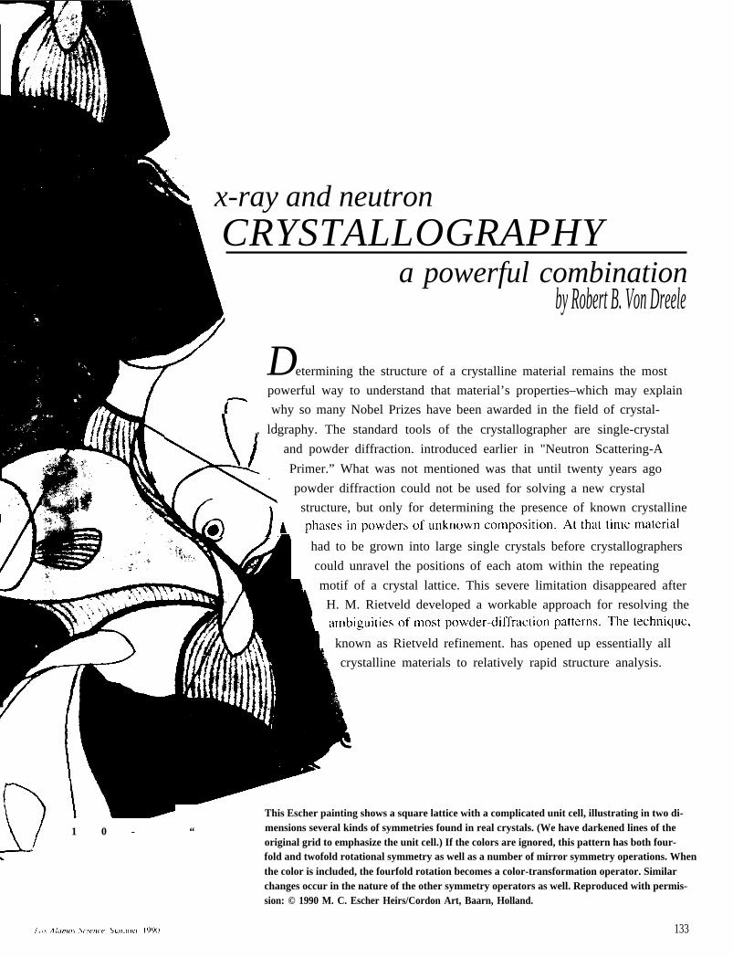
This Escher painting shows a square lattice with a complicated unit cell, illustrating in two di-
1 0 - “ mensions several kinds of symmetries found in real crystals. (We have darkened lines of theoriginal grid to emphasize the unit cell.) If the colors are ignored, this pattern has both four-fold and twofold rotational symmetry as well as a number of mirror symmetry operations. Whenthe color is included, the fourfold rotation becomes a color-transformation operator. Similarchanges occur in the nature of the other symmetry operators as well. Reproduced with permis-sion: © 1990 M. C. Escher Heirs/Cordon Art, Baarn, Holland.
133
X-Ray and Neutron Crystallography
This article presents a further improvement in powder-pattern analysis–that ofcombining x-ray and neutron diffraction data. We used this combination to makethe first unambiguous determination of the structures of certain high-temperature su-perconductors and have since produced a portable software package for use by allcrystallographers who collect both x-ray and neutron data. Here we will discuss theconcepts and techniques that make the combination so useful and some of our recentresults, including the determination of fractional occupancies by different elementsat single atomic sites in a crystal. First, however, we need to extend the concepts ondiffraction introduced in the primer.
What Is a Crystal?
Most solids are crystals: They consist of very many repetitions of a single motifor “unit cell,” of atoms. These repetitions occur at a regular array of points in threedimensions, a “lattice.” The opening illustration is a two-dimensional analogue of acrystal. The unit cell there is square, and contains several objects each arranged ina particular way relative to the others. One question about this pattern is how muchinformation one needs in order to reproduce it. Clearly, one need only describe asingle object (a fish), the set of rules for positioning it and the other objects in theunit cell (the fish of other colors), and the dimension of the unit cell itself. With onlythis information the entire pattern can be laid out to infinity. The classification ofhow the objects are positioned in the unit cell (in most crystals these positions aresymmetrical) and of how the unit cells repeat is the mathematical theory of spatialsymmetry, which is a branch of group theory (see the sidebar “Crystal SymmetryGroups”).
The crystallographer’s goal is to measure the lengths and angles of the edges ofthe unit cell (the “lattice parameters”) and, more important, the arrangement of theatoms within the unit cell. Many kinds of arrangements are possible, for example,the interlacing of long molecular chains in a crystallized protein, or the stacking ofmetal and oxygen atoms in a superconducting oxide, but in any crystal the arrange-ment is the same in every unit cell. Why should atoms and molecules form such or-derly structures? A solid holds together because the atoms and molecules in it areattracted to each other. Thus the minimum-energy configuration of the solid occurswhen its constituents are in as close contact as possible with their neighbors. Thiscriterion is usually realized by a regular array, just as bricks in a neat stack are incloser contact and take up less space than bricks in a jumbled pile.
The unit cell of a crystal is extremely small, typically 10 angstroms (10-7 cen-timeter) on a side, whereas the sides of crystals in a powder may be 1000 to 100,000times larger. An equivalent stack of bricks, each 20 centimeters on a side, would ex-tend between 200 meters and 20 kilometers, The disparity in size between a unit celland a crystal is so vast that we can model a crystal as if it contained an infinite num-ber of unit cells in all directions. This approximation has an enormous simplifyingeffect on a mathematical description of a crystal because we need to describe onlythe unit cell and can ignore the crystal as a whole except to note that the unit cellrepeats indefinitely in all directions.
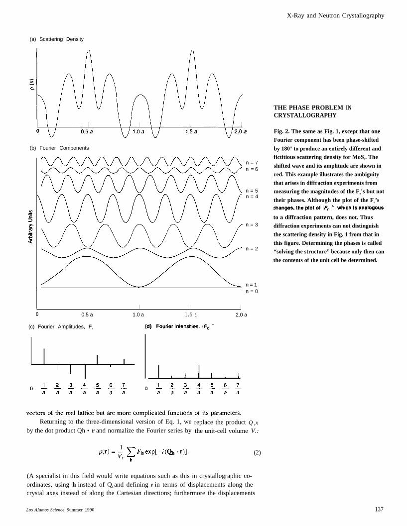
With these ideas in mind, we can start with crystallographic mathematics andthen connect it with the way a crystal scatters neutrons (reversing the plan of theprimer). How do we mathematically describe a crystal? First, the description mustreflect what we actually observe about a crystal. We “see” atoms in a crystal by scat-tering neutrons or x rays from them, so the mathematical model needs to describe thedensity of scattering power, p (r), a function of position, r, within the crystal. Thisscattering density is smooth and usually real and positive. (In some special cases itcan be negative or even complex.) Second, the function needs to repeat infinitely inall directions to match the repetition of the unit cells. In one dimension p(x) mightlook like the curve in Fig. la, which gives the x-ray scattering density along one di-
134 Los Alamos Science Summer 1990
X-Ray and Neutron Crystallography
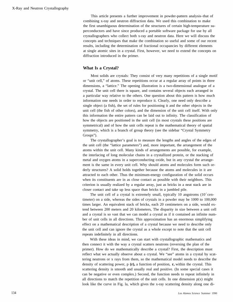
rection in molybdenum disulfide for two unit-cell repeats. The tallest peaks repre-sent the scattering density around the molybdenum atoms; the smaller peaks on eitherside correspond to the sulfur atoms. Like any periodic function, the variation of thescattering density with position x along the repeat direction can be expressed as aninfinite sum of sine and cosine functions, or in other words, as a Fourier series in onedimension:
Here n is an integer, a is the length of the unit cell in the x direction, and Qn =
Each term represents a stationary wave, or “Fourier component,” of scattering densitywhose wavelength is a/n, so that in the repeat distance a the wave undergoes exactlyn oscillations. Thus the sum in Eq. 1 contains only waves that have a as a repeat
I distance. Each stationary wave has an amplitude F., which for the MoS2 structure iseither positive or negative. In the most general case Fn can be complex.
Just as the displacement, x, can be represented by a vector in one-dimensional
I one-dimensional “reciprocal space.” These “reciprocal-lattice” vectors define a rowof equally spaced points, labeled by the values of n. All the remaining reciprocalspace is empty. The points are called the “reciprocal lattice” because their spacing is1/a, the reciprocal of the real-lattice spacing. (The name “reciprocal space” has thesame origin.) Their locations depend only on a, the periodicity of the real lattice, andnot on the contents of the unit cell. In Fig. 1c the amplitude Fn of the nth Fouriercomponent of p(x) for MoS2 is plotted at the reciprocal-lattice point n/a.
Thinking of the Qn's as one-dimensional vectors (the wave vectors of the Fourier
I components), we note from the definition of the Qn's and the discussion of diffrac-tion in the primer that when the momentum transfer in a diffraction experiment
In crystallographic terminology the Fn's are called structure factors; unfortunately the
ever the nomenclature, crystallographers frequently describe crystals in reciprocalspace because the quantities they measure directly are the reciprocal-lattice vectors
I of Fig. 1 whose significance will be discussed later.In order to extend Eq. 1 to descriptions of three-dimensional crystals, we replace
a real lattice whose three axes are mutually perpendicular, as shown in Fig. 3a. Thenthe natural coordinates are orthogonal, and
Here a, b, and c are the repeat distances along the three axes of the unit cell, or lat-tice spacings, and the integer triplet h = (hkl) gives the components of Qh alongthe three axes of the reciprocal-lattice unit cell, measured in units of the reciprocal-lattice repeat distances a* = 1 /a, b* = 1 /b, and c* = l/c. Thus, in analogywith the one-dimensional case, the integer triplets h specify all the possible Qh val-ues, that is, all the wave vectors of Fourier components of the three-dimensionalscattering-density distribution, Each Qh is perpendicular to a stack of parallel planes
tween those planes, commonly called the “d-spacing”. Each h labels a set of planes
Los Alamos Science Summer 1990 135
X-Ray and Neutron Crystallography
A ONE-DIMENSIONAL LATTICEAND ITS RECIPROCAL-SPACEREPRESENTATION
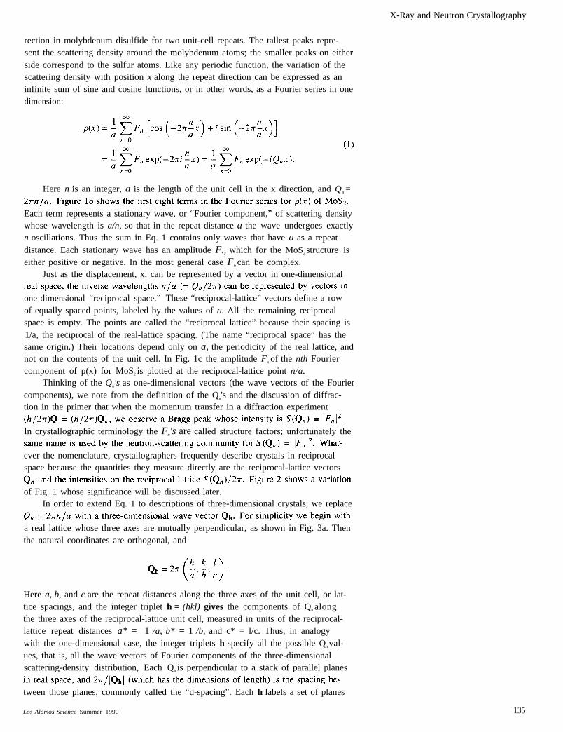
Fig. 1. (a) The x-ray scattering density
aiong one direction of molybdenum disulfide
illustrates a one-dimensional lattice with
a unit ceil of length a. (b) The first eight
Fourier components (n = O to 7) in Eq. 1
for the scattering-density function in (a).
Note that the phase of some of the waves is
offset by 180° with respect to others. (c) The
amplitudes Fn of the Fourier components from
(b) plotted in reciprocal space. The reciprocal
is a -1, the reciprocal of the lattice spacingin real space. Note that some amplitudes are
negative (those of waves shifted in phase by
180° with respect to the waves with positive
S(Qn), plotted in reciprocal space. Thispattern of intensities would be obtained from
a diffraction experiment. This pattern reveals
the size of the unit cell, but as explained in
Fig. 2 does not yield a unique determination
of the contents of the unit cell.
136
Scattering Density
s
o
Mo
0.5 a 1.0 a 1.5 a
Fourier Components
s
2.0 a
0.5 a 1.0 a 1.5 a
Fourier Amplitudes, Fn
2.0 a
perpendicular to Qh. Together the h’s specify all the sets of planes that pass throughunit cells in a periodic way. Therefore just as in one dimension a sum over the wave
sions a sum over the wave vectors Qh, or over the h, is all we need to describe p (r)for a crystal. The integer components hkl of h are identical to the Miller indices thatcrystallographers use to label faces along which crystals break. More important, the
Qh are the special wave vectors Q at which Bragg scattering can occur, as defined in
are still perpendicular tovided by the d-spacings.vectors of the reciprocal
Note that the Qh must be defined in terms of the translationlattice, which are no longer simply parallel to the translation
Los Alamos Science Summer 1990
X-Ray and Neutron Crystallography
(a) Scattering Density
(b) Fourier Components
n = 7n = 6
n = 5n = 4
n = 3
n = 2
n = 1n = 0
o 0.5 a 1.0 a 1.5 a 2.0 a
(c) Fourier Amplitudes, Fn
Returning to the three-dimensional version of Eq. 1, weby the dot product Qh • r and normalize the Fourier series by
replace the product Q nx
the unit-cell volume V.:
(2)
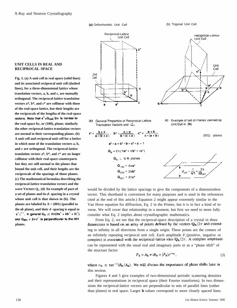
THE PHASE PROBLEMCRYSTALLOGRAPHY
IN
Fig. 2. The same as Fig. 1, except that one
Fourier component has been phase-shifted
by 180° to produce an entirely different andfictitious scattering density for MoS2. The
shifted wave and its amplitude are shown in
red. This example illustrates the ambiguity
that arises in diffraction experiments frommeasuring the magnitudes of the Fn’s but not
their phases. Although the plot of the Fn’s
to a diffraction pattern, does not. Thus
diffraction experiments can not distinguish
the scattering density in Fig. 1 from that in
this figure. Determining the phases is called
“solving the structure” because only then can
the contents of the unit cell be determined.
(A specialist in this field would write equations such as this in crystallographic co-ordinates, using h instead of Qh and defining r in terms of displacements along thecrystal axes instead of along the Cartesian directions; furthermore the displacements
Los AIamos Science Summer 1990 137
X-Ray and Neutron Crystallography
UNIT CELLS IN REAL ANDRECIPROCAL SPACE
Fig. 3. (a) A unit cell in real apace (solid lines)
and its associated reciprocal unit cell (dashedlines), for a three-dimensional lattice whose
translation vectors, a, b, and c, are mutually
orthogonal. The reciprocal-lattice translationvectors a*, b*, and c* are collinear with those
of the real-space lattice, but their lengths arethe reciprocals of the Iengtha of the real-space
the real-space bc, or (100), plane; similarly
the other reciprocal-lattice translation vectors
are normal to their corresponding planes. (b)A unit cell and reciprocal unit cell for a lattice
in which none of the translation vectors a, b,
and c are orthogonal. The reciprocal-lattice
translation vectors a*, b*, and c* are no longercollinear with their real-space counterparts
but they are still normal to the planes that
bound the unit cell, and their lengths are thereciprocals of the spacings of those planes.
(c) The mathematical formulaa describing thereciprocal-lattice translation vectors and the
wave Vectors Qh. (d) An example of part of
a set of planes and its d- spacing in a crystal
whose unit cell is that shown in (b). The
planes are labeled by h = (001) (parallel to
the ab plane), and their d -spacing is equal to
planes.
138
(a) Orthorhombic Unit Cell
Reciprocal-Lattice
\ Unit Cell
(b) Trigonal Unit Cell
(001) planes
would be divided by the lattice spacings to give the components of a dimensionlessvector. This shorthand is convenient for many purposes and is used in the referencescited at the end of this article.) Equation 2 might appear extremely similar to theVan Hove equation for diffraction, Eq. 2 in the Primer, but it is in fact a kind of in-verse. We will cover that relationship in a moment, but first we need to more fullyconsider what Eq. 2 implies about crystallographic mathematics.
From Eq. 2, we see that the reciprocal-space description of a crystal in three
ing to infinity in all directions from a single origin. These points are the comers ofan infinitely repeating reciprocal unit cell. Each amplitude Fh (positive, negative or
can be represented with the usual real and imaginary parts or as a “phase shift” ofthe structure factor:
(3)
this section.Figures 4 and 5 give examples of two-dimensional periodic scattering densities
and their representations in reciprocal space (their Fourier transforms). In two dimen-sions the reciprocal-lattice vectors are perpendicular to sets of parallel lines (ratherthan planes) in real space. Larger h values correspond to more closely spaced lines.
Los Alamos Science Summer 1990
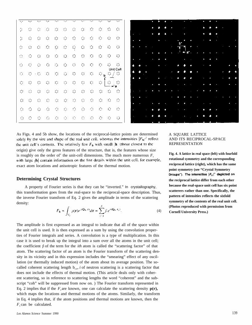
As Figs. 4 and 5b show, the locations of the reciprocal-lattice points are determined
origin) give only the gross features of the structure, that is, the features whose sizeis roughly on the order of’ the unit-cell dimensions. The much more numerous Fh
exact atom locations and anisotropic features of the thermal motion.
Determining Crystal Structures
A property of Fourier series is that they can be “inverted.” In crystallography,
this transformation goes from the real-space to the reciprocal-space description. Thus,the inverse Fourier transform of Eq. 2 gives the amplitude in terms of the scatteringdensity:
(4)
The amplitude is first expressed as an integral to indicate that all of the space withinthe unit cell is used. It is then expressed as a sum by using the convolution proper-ties of Fourier integrals and series. A convolution is a type of multiplication. In thiscase it is used to break up the integral into a sum over all the atoms in the unit cell;the coefficient fi of the term for the ith atom is called the “scattering factor” of thatatom. The scattering factor of an atom is the Fourier transform of the scattering den-sity in its vicinity and in this expression includes the “smearing” effect of any oscil-lation (or thermally induced motion) of the atom about its average position. The so-called coherent scattering length bcoh, i of neutron scattering is a scattering factor thatdoes not include the effects of thermal motion. (This article deals only with coher-ent scattering, so in reference to scattering lengths the word “coherent” and the sub-script “coh” will be suppressed from now on. ) The Fourier transform represented inEq. 2 implies that if the Fh are known, one can calculate the scattering density p(r),which maps the locations and thermal motions of the atoms. Similarly, the transformin Eq. 4 implies that, if the atom positions and thermal motions are known, then theFh can be calculated.
A SQUARE LATTICEAND ITS RECIPROCAL-SPACEREPRESENTATION
Fig. 4. A lattice in real space (left) with fourfoldrotational symmetry and the corresponding
reciprocal lattice (right), which has the same
point symmetry (see “Crystal Symmetry
the reciprocal lattice differ from each other
because the real-space unit cell has six point
scatterers rather than one. Specifically, thepattern of intensities reflects the sixfold
symmetry of the contents of the real unit cell.(Photos reproduced with permission from
Cornell University Press.)
Los Alamos Science Summer 1990 139
X-Ray and Neutron Crystallography
●
● ● ●
do,
● ● ●
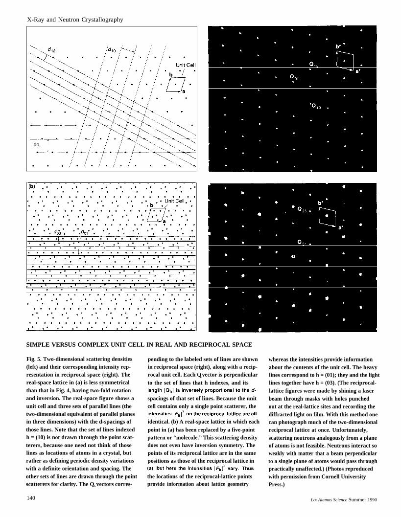
SIMPLE VERSUS COMPLEX UNIT CELL IN REAL AND RECIPROCAL SPACE
Fig. 5. Two-dimensional scattering densities(left) and their corresponding intensity rep-resentation in reciprocal space (right). Thereal-space lattice in (a) is less symmetricalthan that in Fig. 4, having two-fold rotationand inversion. The real-space figure shows aunit cell and three sets of parallel lines (thetwo-dimensional equivalent of parallel planesin three dimensions) with the d-spacings ofthose lines. Note that the set of lines indexedh = (10) is not drawn through the point scat-terers, because one need not think of thoselines as locations of atoms in a crystal, butrather as defining periodic density variationswith a definite orientation and spacing. Theother sets of lines are drawn through the pointscatterers for clarity. The Qh vectors corres-
140
pending to the labeled sets of lines are shownin reciprocal space (right), along with a recip-rocal unit cell. Each Qh vector is perpendicularto the set of lines that h indexes, and its
spacings of that set of lines. Because the unitcell contains only a single point scatterer, the
identical. (b) A real-space lattice in which eachpoint in (a) has been replaced by a five-pointpattern or “molecule.” This scattering densitydoes not even have inversion symmetry. Thepoints of its reciprocal lattice are in the samepositions as those of the reciprocal lattice in
the locations of the reciprocal-lattice pointsprovide information about lattice geometry
whereas the intensities provide informationabout the contents of the unit cell. The heavylines correspond to h = (01); they and the lightlines together have h = (03). (The reciprocal-lattice figures were made by shining a laserbeam through masks with holes punchedout at the real-lattice sites and recording thediffracted light on film. With this method onecan photograph much of the two-dimensionalreciprocal lattice at once. Unfortunately,scattering neutrons analogously from a planeof atoms is not feasible. Neutrons interact soweakly with matter that a beam perpendicularto a single plane of atoms would pass throughpractically unaffected.) (Photos reproducedwith permission from Cornell UniversityPress.)
LOS Alamos Science Summer 1990
X-Ray and Neutron Crystallography
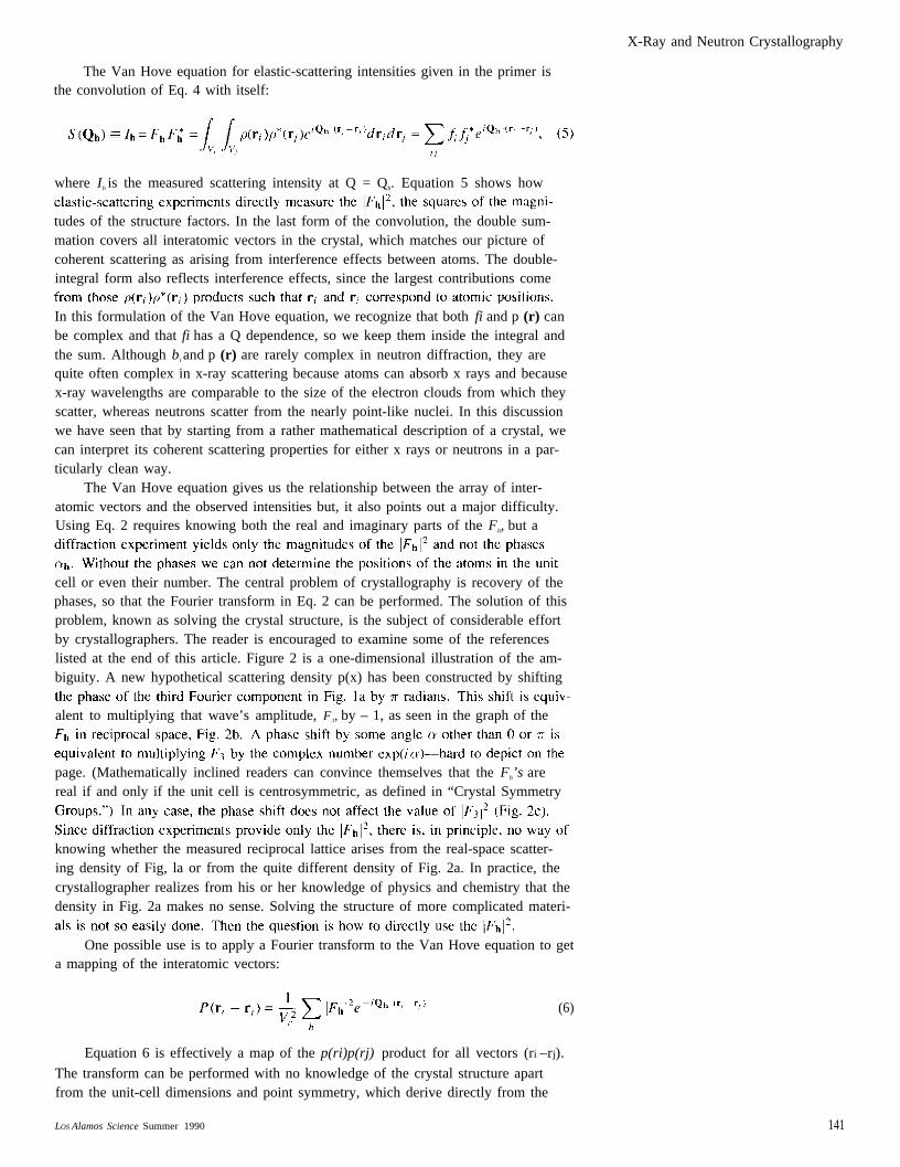
The Van Hove equation for elastic-scattering intensities given in the primer isthe convolution of Eq. 4 with itself:
where Ih is the measured scattering intensity at Q = Qh. Equation 5 shows how
tudes of the structure factors. In the last form of the convolution, the double sum-mation covers all interatomic vectors in the crystal, which matches our picture ofcoherent scattering as arising from interference effects between atoms. The double-integral form also reflects interference effects, since the largest contributions come
In this formulation of the Van Hove equation, we recognize that both fi and p (r) canbe complex and that fi has a Q dependence, so we keep them inside the integral andthe sum. Although b i and p (r) are rarely complex in neutron diffraction, they arequite often complex in x-ray scattering because atoms can absorb x rays and becausex-ray wavelengths are comparable to the size of the electron clouds from which theyscatter, whereas neutrons scatter from the nearly point-like nuclei. In this discussionwe have seen that by starting from a rather mathematical description of a crystal, wecan interpret its coherent scattering properties for either x rays or neutrons in a par-ticularly clean way.
The Van Hove equation gives us the relationship between the array of inter-atomic vectors and the observed intensities but, it also points out a major difficulty.Using Eq. 2 requires knowing both the real and imaginary parts of the Fh, but a
cell or even their number. The central problem of crystallography is recovery of thephases, so that the Fourier transform in Eq. 2 can be performed. The solution of thisproblem, known as solving the crystal structure, is the subject of considerable effortby crystallographers. The reader is encouraged to examine some of the referenceslisted at the end of this article. Figure 2 is a one-dimensional illustration of the am-biguity. A new hypothetical scattering density p(x) has been constructed by shifting
alent to multiplying that wave’s amplitude, F3, by – 1, as seen in the graph of the
page. (Mathematically inclined readers can convince themselves that the Fh’s arereal if and only if the unit cell is centrosymmetric, as defined in “Crystal Symmetry
knowing whether the measured reciprocal lattice arises from the real-space scatter-ing density of Fig, la or from the quite different density of Fig. 2a. In practice, thecrystallographer realizes from his or her knowledge of physics and chemistry that thedensity in Fig. 2a makes no sense. Solving the structure of more complicated materi-
One possible use is to apply a Fourier transform to the Van Hove equation to geta mapping of the interatomic vectors:
(6)
Equation 6 is effectively a map of the p(ri)p(rj) product for all vectors (ri –rj).
The transform can be performed with no knowledge of the crystal structure apartfrom the unit-cell dimensions and point symmetry, which derive directly from the
LOS Alamos Science Summer 1990 141
X-Ray and Neutron Crystallography
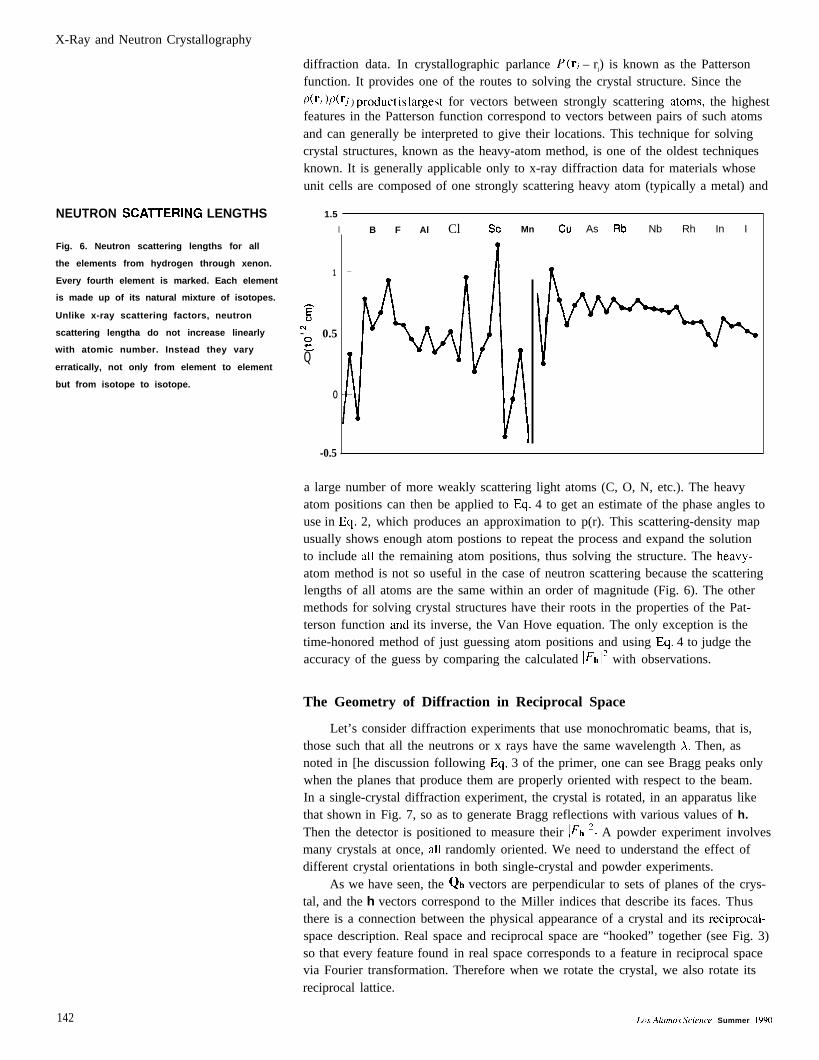
NEUTRON SCAITERING LENGTHS
Fig. 6. Neutron scattering lengths for all
the elements from hydrogen through xenon.
Every fourth element is marked. Each element
is made up of its natural mixture of isotopes.
Unlike x-ray scattering factors, neutron
scattering lengtha do not increase linearly
with atomic number. Instead they vary
erratically, not only from element to element
but from isotope to isotope.
diffraction data. In crystallographic parlance P(ri – rj) is known as the Pattersonfunction. It provides one of the routes to solving the crystal structure. Since the
dri)/Xr; ) Product is largest for vectors between strongly scattering atoms, the highestfeatures in the Patterson function correspond to vectors between pairs of such atomsand can generally be interpreted to give their locations. This technique for solvingcrystal structures, known as the heavy-atom method, is one of the oldest techniquesknown. It is generally applicable only to x-ray diffraction data for materials whoseunit cells are composed of one strongly scattering heavy atom (typically a metal) and
1.5
I
1
gN~ 0.5-zQ
o
-0.5
B F Al Cl SC Mn Cu As Rb Nb Rh In I
a large number of more weakly scattering light atoms (C, O, N, etc.). The heavyatom positions can then be applied to Eq. 4 to get an estimate of the phase angles touse in Eq. 2, which produces an approximation to p(r). This scattering-density mapusually shows enough atom postions to repeat the process and expand the solutionto include all the remaining atom positions, thus solving the structure. The heavy-atom method is not so useful in the case of neutron scattering because the scatteringlengths of all atoms are the same within an order of magnitude (Fig. 6). The othermethods for solving crystal structures have their roots in the properties of the Pat-terson function and its inverse, the Van Hove equation. The only exception is thetime-honored method of just guessing atom positions and using Eq. 4 to judge theaccuracy of the guess by comparing the calculated l~hla with observations.
The Geometry of Diffraction in Reciprocal Space
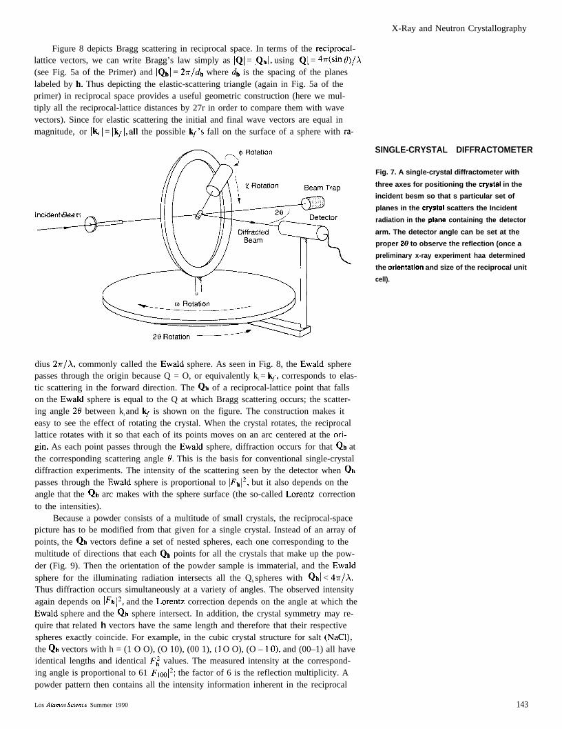
Let’s consider diffraction experiments that use monochromatic beams, that is,those such that all the neutrons or x rays have the same wavelength A. Then, asnoted in [he discussion following Eq. 3 of the primer, one can see Bragg peaks onlywhen the planes that produce them are properly oriented with respect to the beam.In a single-crystal diffraction experiment, the crystal is rotated, in an apparatus likethat shown in Fig. 7, so as to generate Bragg reflections with various values of h.Then the detector is positioned to measure their l~hlz. A powder experiment involvesmany crystals at once, all randomly oriented. We need to understand the effect ofdifferent crystal orientations in both single-crystal and powder experiments.
As we have seen, the Qh vectors are perpendicular to sets of planes of the crys-tal, and the h vectors correspond to the Miller indices that describe its faces. Thusthere is a connection between the physical appearance of a crystal and its reciprocal-space description. Real space and reciprocal space are “hooked” together (see Fig. 3)so that every feature found in real space corresponds to a feature in reciprocal spacevia Fourier transformation. Therefore when we rotate the crystal, we also rotate itsreciprocal lattice.
142 L(H Alamos Scietzce Summer 1990
X-Ray and Neutron Crystallography
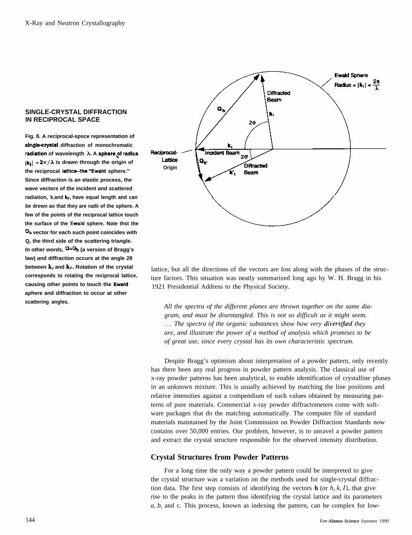
Figure 8 depicts Bragg scattering in reciprocal space. In terms of the reciprocal-lattice vectors, we can write Bragg’s law simply as IQI = IQhl, using IQI = 4n(sin O)/A(see Fig. 5a of the Primer) and IQhl = 2n/dh where dh is the spacing of the planeslabeled by h. Thus depicting the elastic-scattering triangle (again in Fig. 5a of theprimer) in reciprocal space provides a useful geometric construction (here we mul-tiply all the reciprocal-lattice distances by 27r in order to compare them with wavevectors). Since for elastic scattering the initial and final wave vectors are equal inmagnitude, or Iki I = Ikf 1, all the possible kf fall on the surface of a sphere with ra-
lllblU151 11 D~dl I I
I u )11
dius 27r/A, commonly called the Ewald sphere. As seen in Fig. 8, the Ewald spherepasses through the origin because Q = O, or equivalently k i = kf, corresponds to elas-tic scattering in the forward direction. The Qh of a reciprocal-lattice point that fallson the Ewald sphere is equal to the Q at which Bragg scattering occurs; the scatter-ing angle 20 between ki and kf is shown on the figure. The construction makes iteasy to see the effect of rotating the crystal. When the crystal rotates, the reciprocallattice rotates with it so that each of its points moves on an arc centered at the or-igin. As each point passes through the Ewald sphere, diffraction occurs for that Qh atthe corresponding scattering angle 0. This is the basis for conventional single-crystaldiffraction experiments. The intensity of the scattering seen by the detector when Qhpasses through the Ewald sphere is proportional to lFh12, but it also depends on theangle that the Qh arc makes with the sphere surface (the so-called Lorentz correctionto the intensities).
Because a powder consists of a multitude of small crystals, the reciprocal-spacepicture has to be modified from that given for a single crystal. Instead of an array ofpoints, the Qh vectors define a set of nested spheres, each one corresponding to themultitude of directions that each Qb points for all the crystals that make up the pow-der (Fig. 9). Then the orientation of the powder sample is immaterial, and the Ewaldsphere for the illuminating radiation intersects all the Qh spheres with IQhl < 47r/A,Thus diffraction occurs simultaneously at a variety of angles. The observed intensityagain depends on l~h 12, and the Lorentz correction depends on the angle at which theEwald sphere and the Qh sphere intersect. In addition, the crystal symmetry may re-quire that related h vectors have the same length and therefore that their respectivespheres exactly coincide. For example, in the cubic crystal structure for salt (NaCl),the Qh vectors with h = (1 O O), (O 10), (00 1), (1 O O), (O – 10), and (00–1) all haveidentical lengths and identical F: values. The measured intensity at the correspond-ing angle is proportional to 61 F1W12; the factor of 6 is the reflection multiplicity. Apowder pattern then contains all the intensity information inherent in the reciprocal
SINGLE-CRYSTAL DIFFRACTOMETER
Fig. 7. A single-crystal diffractometer with
three axes for positioning the cryatal in the
incident besm so that s particular set of
planes in the cryatal scatters the Incident
radiation in the plana containing the detector
arm. The detector angle can be set at the
proper 2f3 to observe the reflection (once a
preliminary x-ray experiment haa determined
the oriantatlon and size of the reciprocal unit
cell).
Los Alamos .$’cience Summer 1990 143
X-Ray and Neutron Crystallography
SINGLE-CRYSTAL DIFFRACTIONIN RECIPROCAL SPACE
Fig. 8. A reciprocal-spsce representation of
single-crystsl diffraction of monochromatic
rediation of wavelength X. A sphere%of redius
Ikil = 27r/A is drawn through the origin of
the reciprocal Iattic+the “Ewald sphere.”
Since diffraction is an elastic process, the
wave vectors of the incident and scattered
radiation, ki and kf, have equal length and can
be drewn ao that they are radii of the sphere. A
few of the points of the reciprocal lattice touch
the surface of the Ewald sphere. Note thst the
Qh vector for each such point coincides with
Q, the third side of the scattering triangle.
In other words, Q=Qh (a version of Bragg’s
law) and diffraction occurs at the angle 28
between ki and kf. Rotation of the crystal
corresponds to rotating the reciprocal lattice,
causing other points to touch the Ewald
aphere and diffraction to occur at other
scattering angles.
Reciprocal-LatficaOrigin
lattice, but all the directions of the vectors are lost along with the phases of the struc-ture factors. This situation was neatly summarized long ago by W. H. Bragg in his1921 Presidential Address to the Physical Society.
All the spectra of the different planes are thrown together on the same dia-gram, and must be disentangled. This is not so difficult as it might seem.. . . The spectra of the organic substances show how very diversijed theyare, and illustrate the power of a method of analysis which promises to beof great use, since every crystal has its own characteristic spectrum.
Despite Bragg’s optimism about interpretation of a powder pattern, only recentlyhas there been any real progress in powder pattern analysis. The classical use ofx-ray powder patterns has been analytical, to enable identification of crystalline phasesin an unknown mixture. This is usually achieved by matching the line positions andrelative intensities against a compendium of such values obtained by measuring pat-terns of pure materials. Commercial x-ray powder diffractometers come with soft-ware packages that do the matching automatically. The computer file of standardmaterials maintained by the Joint Commission on Powder Diffraction Standards nowcontains over 50,000 entries. Our problem, however, is to unravel a powder patternand extract the crystal structure responsible for the observed intensity distribution.
Crystal Structures from Powder Patterns
For a long time the only way a powder pattern could be interpreted to givethe crystal structure was a variation on the methods used for single-crystal diffrac-tion data. The first step consists of identifying the vectors h (or h, k, 1), that giverise to the peaks in the pattern thus identifying the crystal lattice and its parametersa, b, and c. This process, known as indexing the pattern, can be complex for low-
144 LOS Alamos Science Summer 1990
X-Ray and Neutron Crystallography
(a) Reciprocal-Space Geometry
Ewald Sphere/
I(b) Powder-Diffraction Pattern
“!-l-u~1
20
symmetry crystals but is quite easy for cubic structures. In that case the relationshipbetween h and d-spacing gives
# = a’h2 + k2 + 12
(7),
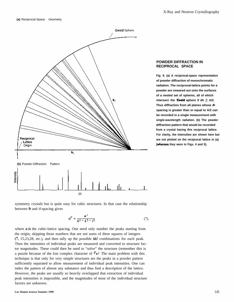
where a is the cubic-lattice spacing. One need only number the peaks starting fromthe origin, skipping those numbers that are not sums of three squares of integers(7, 15,23,28, etc.), and then tally up the possible hkl combinations for each peak.Then the intensities of individual peaks are measured and converted to structure fac-tor magnitudes. These could then be used to “solve” the structure (remember this isa puzzle because of the lost complex character of ~h). The main problem with thistechnique is that only for very simple structures are the peaks in a powder patternsufficiently separated to allow measurement of individual peak intensities. One canindex the pattern of almost any substance and thus find a description of the lattice.However, the peaks are usually so heavily overlapped that extraction of individualpeak intensities is impossible, and the magnitudes of most of the individual structurefactors are unknown.
POWDER DIFFRACTION INRECIPROCAL SPACE
Fig. 9. (a) A reciprocal-space representation
of powder diffraction of monochromatic
radiation. The reciprocal-lattice points for a
powder are smeared out onto the surfaces
of a nested set of spheres, all of which
intersect the Ewald aphere if dh > A/2.
Thus diffraction from all planes whose d-
spacing is greater than or equal to A/2 can
be recorded in a single measurement with
single-wavelength radiation. (b) The powder
diffraction pattern that would be recorded
from a crystal having this reciprocal lattice.
For clarity, the intensities are shown here but
are not plotted on the reciprocal lattice in (a)
(whereaa they were in Figs. 4 and 5).
Los Alamos Science Summer 1990 145
X-Ray and Neutron Crystallography
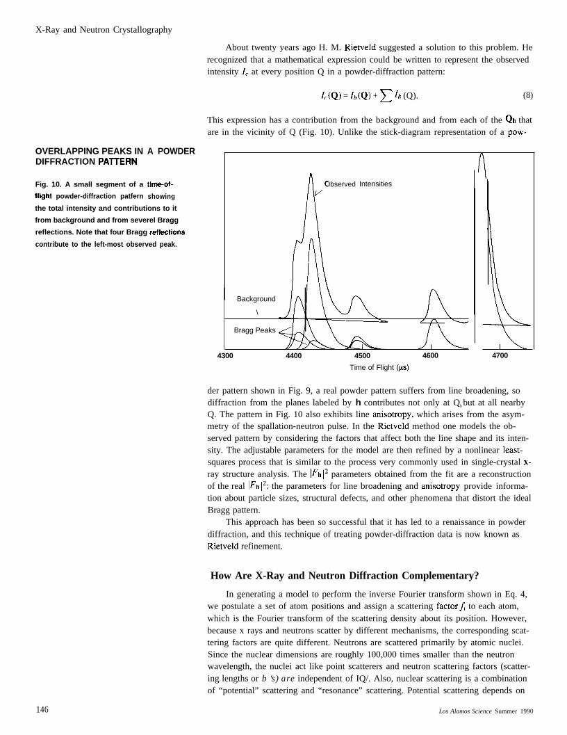
OVERLAPPING PEAKS INDIFFRACTION PA71ERN
Fig. 10. A small segment of a
fllght powder-diffraction patfern
A POWDER
tima-of-
showing
the total intensity and contributions to it
from background and from severel Bragg
reflections. Note that four Bragg reflaetions
contribute to the left-most observed peak.
146
About twenty years ago H. M. Rietveld suggested a solution to this problem. Herecognized that a mathematical expression could be written to represent the observedintensity IC at every position Q in a powder-diffraction pattern:
1.(Q) = Zb(Q) + ~ lh (Q). (8)
This expression has a contribution from the background and from each of the Qh thatare in the vicinity of Q (Fig. 10). Unlike the stick-diagram representation of a pow-
AObserved
/
A
Intensities
Background
\
Bragg Peaks
4300 4400 4500 4600
\
1
I4700
Time of Flight (ys)
der pattern shown in Fig. 9, a real powder pattern suffers from line broadening, sodiffraction from the planes labeled by h contributes not only at Qh but at all nearbyQ. The pattern in Fig. 10 also exhibits line anisotropy, which arises from the asym-metry of the spallation-neutron pulse. In the Rietveld method one models the ob-served pattern by considering the factors that affect both the line shape and its inten-sity. The adjustable parameters for the model are then refined by a nonlinear least-squares process that is similar to the process very commonly used in single-crystal x-ray structure analysis. The l~h 12 parameters obtained from the fit are a reconstructionof the real ]Fh 12; the parameters for line broadening and anisotropy provide informa-tion about particle sizes, structural defects, and other phenomena that distort the idealBragg pattern.
This approach has been so successful that it has led to a renaissance in powderdiffraction, and this technique of treating powder-diffraction data is now known asRietveld refinement.
How Are X-Ray and Neutron Diffraction Complementary?
In generating a model to perform the inverse Fourier transform shown in Eq. 4,we postulate a set of atom positions and assign a scattering factorfi to each atom,which is the Fourier transform of the scattering density about its position. However,because x rays and neutrons scatter by different mechanisms, the corresponding scat-tering factors are quite different. Neutrons are scattered primarily by atomic nuclei.Since the nuclear dimensions are roughly 100,000 times smaller than the neutronwavelength, the nuclei act like point scatterers and neutron scattering factors (scatter-ing lengths or b ‘s) are independent of IQ/. Also, nuclear scattering is a combinationof “potential” scattering and “resonance” scattering. Potential scattering depends on
Los Alamos Science Summer 1990
X-Ray and Neutron Crystallography
the number of nuclear particles and resonance scattering results from neutron absorp-tion by the nucleus. These two factors sometimes add and sometimes subtract to giveneutron scattering lengths that vary erratically from one element to another and fromone isotope to another (see Fig. 6).
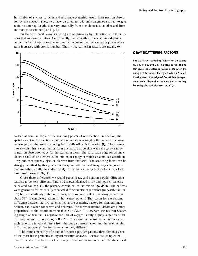
On the other hand, x-ray scattering occurs primarily by interaction with the elec-trons that surround an atom. Consequently, the strength of the scattering dependson the number of electrons that surround an atom so that the scattering power of anatom increases with atomic number. Thus, x-ray scattering factors are usually ex-
30~ ‘-RA’SCA”ER’NGFACT”RS
25
20
10
5
coFeTi
co’Mgo
I I 1 I I I I I Io 2 4 6 8
0 (A-’)
pressed as some multiple of the scattering power of one electron. In addition, thespatial extent of the electron cloud around an atom is roughly the same as the x-raywavelength, so the x-ray scattering factor falls off with increasing /Q1. The scatteredintensity also has a contribution from anomalous dispersion when the x-ray energyis near an absorption edge for the scattering atom. The absorption edge for an innerelectron shell of an element is the minimum energy at which an atom can absorb anx ray and consequently eject an electron from that shell. The scattering factor can bestrongly modified by this process and acquire both real and imaginary componentsthat are only partially dependent on IQI. Thus the scattering factors for x rays looklike those shown in Fig. 11.
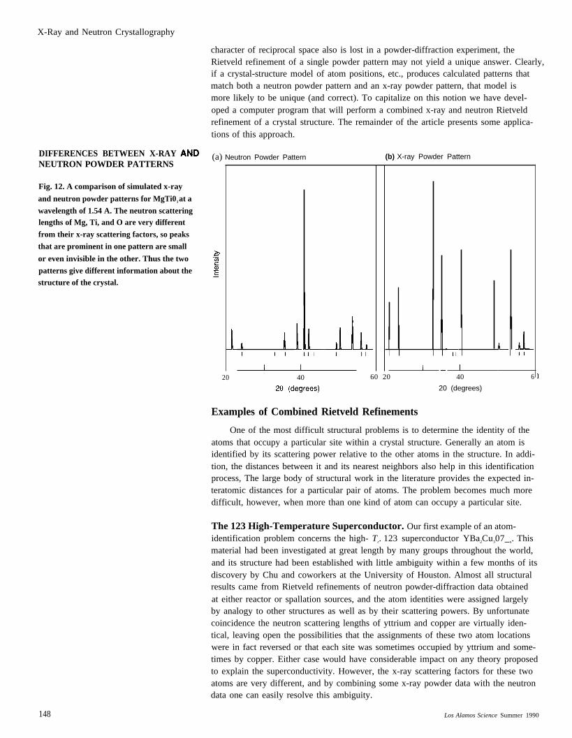
Given these differences we would expect x-ray and neutron powder-diffractionpatterns to be very different. Figure 12 shows idealized x-ray and neutron patternscalculated for MgTi03, the primary constituent of the mineral geikielite. The patternswere generated for essentially identical diffractometer experiments (impossible in reallife) but are startlingly different. In fact, the strongest peak in the x-ray pattern (atabout 32°) is completely absent in the neutron pattern! The reason for the extremedifference between the two patterns lies in the scattering factors for titanium, mag-nesium, and oxygen for x-rays and neutrons. The x-ray scattering factors are simplyproportional to the atomic number; thus ~Ti > & > fo. However, the neutron Scatter-ing length of titanium is negative and that of oxygen is only slightly larger than thatof magnesium, or bo > bM~ > () > bTi. Therefore the neutron structure factor foreach reflection is very different from the x-ray structure factor, and the peak heightsin the two powder-diffraction patterns are very different.
The complementarily of x-ray and neutron powder patterns then eliminates oneof the most basic problems in crystal-structure analysis. Because the complex na-ture of the structure factors is lost in any diffraction measurement and the directional
Los Alamos Science Summer 1990
Fig. 11. X-ray scattering factors for the atoms
O, Mg, Ti, Fe, and Co. The gray curve Iabaled
Co’ gives the scattering factor of Co when the
energy of the incident x rays is a few eV below
the K absorption edge of Co. At this energy,
anomalous dispersion reduces the scattering
fsctor by about 6 electrons at sII Q.
147
X-Ray and Neutron Crystallography
DIFFERENCES BETWEEN X-RAYNEUTRON POWDER PATTERNS
Fig. 12. A comparison of simulated x-ray
and neutron powder patterns for MgTi03 at a
wavelength of 1.54 A. The neutron scatteringlengths of Mg, Ti, and O are very different
from their x-ray scattering factors, so peaks
that are prominent in one pattern are small
or even invisible in the other. Thus the two
patterns give different information about thestructure of the crystal.
character of reciprocal space also is lost in a powder-diffraction experiment, theRietveld refinement of a single powder pattern may not yield a unique answer. Clearly,if a crystal-structure model of atom positions, etc., produces calculated patterns thatmatch both a neutron powder pattern and an x-ray powder pattern, that model ismore likely to be unique (and correct). To capitalize on this notion we have devel-oped a computer program that will perform a combined x-ray and neutron Rietveldrefinement of a crystal structure. The remainder of the article presents some applica-tions of this approach.
(a) Neutron Powder Pattern (b) X-ray Powder Pattern
20 40 60 20 40 6
20 (degrees)
Examples of Combined Rietveld Refinements
One of the most difficult structural problems is to determine the identity of theatoms that occupy a particular site within a crystal structure. Generally an atom isidentified by its scattering power relative to the other atoms in the structure. In addi-tion, the distances between it and its nearest neighbors also help in this identificationprocess, The large body of structural work in the literature provides the expected in-teratomic distances for a particular pair of atoms. The problem becomes much moredifficult, however, when more than one kind of atom can occupy a particular site.
)
The 123 High-Temperature Superconductor. Our first example of an atom-identification problem concerns the high- Tc. 123 superconductor YBa2Cu307_x. Thismaterial had been investigated at great length by many groups throughout the world,and its structure had been established with little ambiguity within a few months of itsdiscovery by Chu and coworkers at the University of Houston. Almost all structuralresults came from Rietveld refinements of neutron powder-diffraction data obtainedat either reactor or spallation sources, and the atom identities were assigned largelyby analogy to other structures as well as by their scattering powers. By unfortunatecoincidence the neutron scattering lengths of yttrium and copper are virtually iden-tical, leaving open the possibilities that the assignments of these two atom locationswere in fact reversed or that each site was sometimes occupied by yttrium and some-times by copper. Either case would have considerable impact on any theory proposedto explain the superconductivity. However, the x-ray scattering factors for these twoatoms are very different, and by combining some x-ray powder data with the neutrondata one can easily resolve this ambiguity.
148 Los Alamos Science Summer 1990
X-Ray and Neutron Crystallography
Cu ~
z
L/
x
Y
02
‘ 04
01
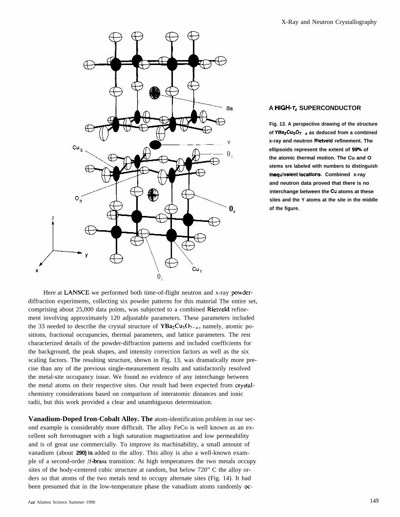
Here at LANSCE we performed both time-of-flight neutron and x-ray powder-diffraction experiments, collecting six powder patterns for this material The entire set,comprising about 25,000 data points, was subjected to a combined Rietveld refine-ment involving approximately 120 adjustable parameters. These parameters includedthe 33 needed to describe the crystal structure of YBazCuqOT_,, namely, atomic po-sitions, fractional occupancies, thermal parameters, and lattice parameters. The restcharacterized details of the powder-diffraction patterns and included coefficients forthe background, the peak shapes, and intensity correction factors as well as the sixscaling factors. The resulting structure, shown in Fig. 13, was dramatically more pre-cise than any of the previous single-measurement results and satisfactorily resolvedthe metal-site occupancy issue. We found no evidence of any interchange betweenthe metal atoms on their respective sites. Our result had been expected from crystal-chemistry considerations based on comparison of interatomic distances and ionicradii, but this work provided a clear and unambiguous determination.
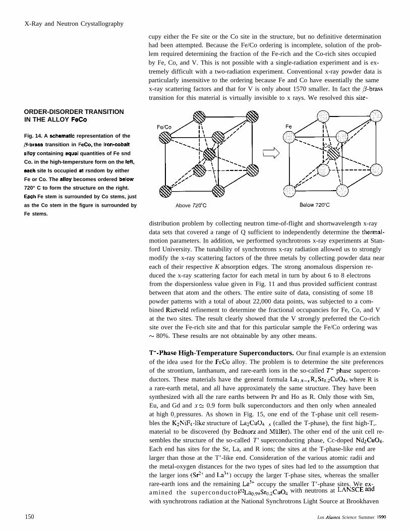
Vanadium-Doped Iron-Cobalt Alloy. The atom-identification problem in our sec-ond example is considerably more difficult. The alloy FeCo is well known as an ex-cellent soft ferromagnet with a high saturation magnetization and low permeabilityand is of great use commercially. To improve its machinability, a small amount ofvanadium (about 290) is added to the alloy. This alloy is also a well-known exam-ple of a second-order ~-brass transition: At high temperatures the two metals occupysites of the body-centered cubic structure at random, but below 720” C the alloy or-ders so that atoms of the two metals tend to occupy alternate sites (Fig. 14). It hadbeen presumed that in the low-temperature phase the vanadium atoms randomly oc-
A HIGH-T. SUPERCONDUCTOR
Fig. 13. A perspective drawing of the structure
of YBa2Cu@_X as deduced from a combined
x-ray and neutron Rietveld refinement. The
ellipsoids represent the extent of 99eA of
the atomic thermal motion. The Cu and O
stems sre labeled with numbers to distinguish
inequivalent Iocationa. Combined x-ray
and neutron data proved that there is no
interchange between the Cu atoms at these
sites and the Y atoms at the site in the middle
of the figure.
Los Alamos Science Summer 1990 149
X-Ray and Neutron Crystallography
ORDER-DISORDER TRANSITIONIN THE ALLOY FeCo
Fig. 14. A schemstlc representation of the
@brsss transition in FeCo, the iron-cobslt
slloy containing equsl quantities of Fe snd
Co. in the high-tempersture form on the ieft,
esch site Is occupied st rsndom by either
Fe or Co. The slioy becomes ordered beiow
720° C to form the structure on the right.
Esch Fe stem is surrounded by Co stems, just
as the Co stem in the figure is surrounded by
Fe stems.
cupy either the Fe site or the Co site in the structure, but no definitive determinationhad been attempted. Because the Fe/Co ordering is incomplete, solution of the prob-lem required determining the fraction of the Fe-rich and the Co-rich sites occupiedby Fe, Co, and V. This is not possible with a single-radiation experiment and is ex-tremely difficult with a two-radiation experiment. Conventional x-ray powder data isparticularly insensitive to the ordering because Fe and Co have essentially the samex-ray scattering factors and that for V is only about 1570 smaller. In fact the ,B-brasstransition for this material is virtually invisible to x rays. We resolved this site-
Above 720”C Beiow 720”C
distribution problem by collecting neutron time-of-flight and shortwavelength x-raydata sets that covered a range of Q sufficient to independently determine the thermal-motion parameters. In addition, we performed synchrotrons x-ray experiments at Stan-ford University. The tunability of synchrotrons x-ray radiation allowed us to stronglymodify the x-ray scattering factors of the three metals by collecting powder data neareach of their respective K absorption edges. The strong anomalous dispersion re-duced the x-ray scattering factor for each metal in turn by about 6 to 8 electronsfrom the dispersionless value given in Fig. 11 and thus provided sufficient contrastbetween that atom and the others. The entire suite of data, consisting of some 18powder patterns with a total of about 22,000 data points, was subjected to a com-bined Rietveld refinement to determine the fractional occupancies for Fe, Co, and Vat the two sites. The result clearly showed that the V strongly preferred the Co-richsite over the Fe-rich site and that for this particular sample the Fe/Co ordering wasN 80%. These results are not obtainable by any other means.
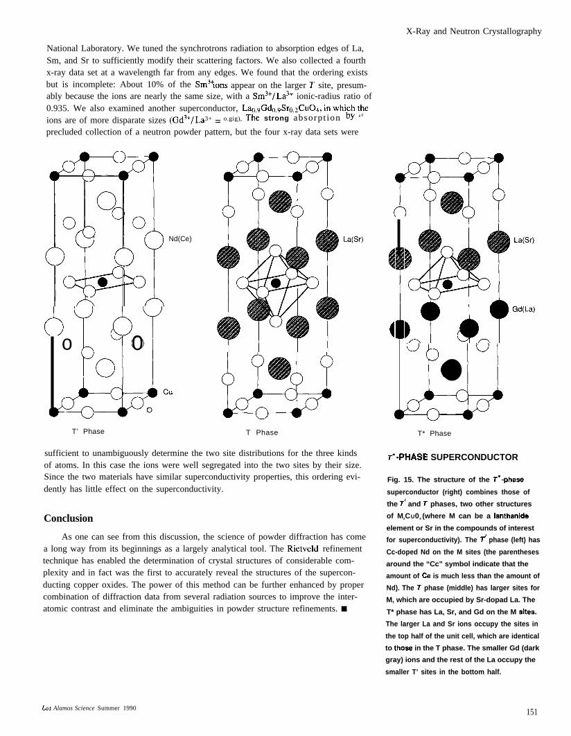
T*-Phase High-Temperature Superconductors. Our final example is an extensionof the idea used for the FeCo alloy. The problem is to determine the site preferencesof the strontium, lanthanum, and rare-earth ions in the so-called T*-phase supercon-ductors. These materials have the general formula Lal.8–,R,Sro.zC@4, where R isa rare-earth metal, and all have approximately the same structure. They have beensynthesized with all the rare earths between Pr and Ho as R. Only those with Sm,Eu, and Gd and x & 0.9 form bulk superconductors and then only when annealedat high 02 pressures. As shown in Fig. 15, one end of the T-phase unit cell resem-bles the KzNiF4-like structure of LazCu04_x (called the T-phase), the first high-T,.material to be discovered (by Bednorz and Mitller). The other end of the unit cell re-sembles the structure of the so-called T’ superconducting phase, Cc-doped NdzCu04.Each end has sites for the Sr, La, and R ions; the sites at the T-phase-like end arelarger than those at the T’-like end. Consideration of the various atomic radii andthe metal-oxygen distances for the two types of sites had led to the assumption thatthe larger ions (S#+ and La3+) occupy the larger T-phase sites, whereas the smallerrare-earth ions and the remaining La3+ occupy the smaller T’-phase sites. We ex-
152smo ~Sro,2Cu04 with neutrons at LANSCE andamined the superconductor L~,gwith synchrotrons radiation at the National Synchrotrons Light Source at Brookhaven
150 Los Akzmos Science Summer 1990
X-Ray and Neutron Crystallography
National Laboratory. We tuned the synchrotrons radiation to absorption edges of La,Sm, and Sr to sufficiently modify their scattering factors. We also collected a fourthx-ray data set at a wavelength far from any edges. We found that the ordering existsbut is incomplete: About 10% of the Sm3+Ions appear on the larger T site, presum-ably because the ions are nearly the same size, with a Sm3+/La3+ ionic-radius ratio of0.935. We also examined another superconductor, Lao9Gdd30.2CuO+ in which the
3+ = o.gig), The strong absorpt ion bY ‘d
ions are of more disparate sizes (Gd3+/Laprecluded collection of a neutron powder pattern, but the four x-ray data sets were
Nd(Ce)
(’-) N(o 00
-’”T’ Phase
La(Sr)
T Phase
sufficient to unambiguously determine the two site distributions for the three kindsof atoms. In this case the ions were well segregated into the two sites by their size.Since the two materials have similar superconductivity properties, this ordering evi-dently has little effect on the superconductivity.
Conclusion
As one can see from this discussion, the science of powder diffraction has comea long way from its beginnings as a largely analytical tool. The Rietveld refinementtechnique has enabled the determination of crystal structures of considerable com-plexity and in fact was the first to accurately reveal the structures of the supercon-ducting copper oxides. The power of this method can be further enhanced by propercombination of diffraction data from several radiation sources to improve the inter-atomic contrast and eliminate the ambiguities in powder structure refinements. ■
(
(
La(Sr)
Gd(La)
uuu
●
T* Phase
T*-PHASE SUPERCONDUCTOR
Fig. 15. The structure of the T’-phaae
superconductor (right) combines those of
the j and T phases, two other structures
of M2CU04 (where M can be a Ianthanide
element or Sr in the compounds of interest
for superconductivity). The T’ phase (left) has
Cc-doped Nd on the M sites (the parentheses
around the “Cc” symbol indicate that the
amount of Ce is much less than the amount of
Nd). The T phase (middle) has larger sites for
M, which are occupied by Sr-dopad La. The
T* phase has La, Sr, and Gd on the M sitea.
The larger La and Sr ions occupy the sites in
the top half of the unit cell, which are identical
to thoae in the T phase. The smaller Gd (dark
gray) ions and the rest of the La occupy the
smaller T’ sites in the bottom half.
Los Alamos Science Summer 1990 151
X-Ray and Neutron Crystallography
Crystal Symmetry Groups
s ymmetry plays an important rolein crystallography. The ways inwhich atoms and molecules are
arranged within a unit cell and unit cellsrepeat within a crystal are governed bysymmetry rules. In ordinary life ourfirst perception of symmetry is whatis known as mirror symmetry. Ourbodies have, to a good approximation,mirror symmetry in which our right sideis matched by our left as if a mirrorpassed along the central axis of ourbodies. Our hands illustrate this mostvividly; so much so that the image iscarried over to crystallography whenone speaks of a molecule as being either“right”- or “left”- handed. Those of uswho live in an old-fashioned duplexwill also recognize that such houses arebuilt with mirror symmetry so that thearrangement of the rooms, hallways, anddoors are disposed about an imaginarymirror passing through the commonwall between the two halves of thehouse. There are many other examplesof this kind of mirror symmetry inordinary life. We can also see morecomplex symmetry in the patternsaround us. It can be found in wallpaperpatterns, floor-tile arrays, cloth designs,flowers, and mineral crystals. The basicmathematics of symmetry also appliesto music, dance (particularly folk andsquare dance), and even the operationsneeded to solve Rubik’s cube.
The rules that govern symmetry arefound in the mathematics of group the-ory. Group theory addresses the way inwhich a certain collection of mathemat-ical “objects” are related to each other.For example, consider all the positiveand negative integers and zero. Theycan constitute a group because undercertain circumstances the relationships
between the integers obey the rules ofgroup theory:● There must be defined a procedure for
combining two elements of the groupto form a third. For the integers onecan choose the addition operation sothat a + b = c is the operation to beperformed and u, b, and c are alwayselements of the group.
● There exists an element of the group,called the identity element and de-noted f, that combines with any otherelement to give the second one un-changed. In the case of the integers,the identity element is zero becauseany integer plus zero gives that inte-ger (a + O = a).
● For every element of the group, thereexists another element that combineswith the first to give the identityelement; these are known as inverseelements. The negative integersconstitute the inverses of the positiveintegers because their pairwise sumsall equal zero, the identity element(a + (–a) = 0).
● Group operations in sequence obeythe associative law. For addition ofintegers this means that (a + b) + c =a+(b+c). Notice that the commutativelaw, a + b = b + a, is not required eventhough it is true for this particulargroup.You might be tempted to say that the
positive integers, when related by mul-tiplication (a x b = c), also constitutea group with the identity element nowbeing one (a x 1 = a). In fact, the pos-itive integers do not constitute a groupunder these conditions because, to obeythe group-theory rules, the nonintegerinverses ( 1 /a) as well as all the ratio-nal fractions (b/a) would have to beincluded. The expanded set of positive
rational numbers is a group undermultiplication, and both it and theinteger group already discussed areexamples of infinite groups becausethey each contain an infinite numberof elements.
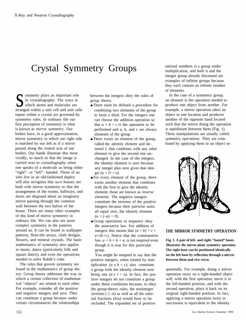
In the case of a symmetry group,an element is the operation needed toproduce one object from another. Forexample, a mirror operation takes anobject in one location and producesanother of the opposite hand locatedsuch that the mirror doing the operationis equidistant between them (Fig. 1).These manipulations are usually calledsymmetry operations. They are com-bined by applying them to an object se-
THE MIRROR SYMMETRY OPERATION
Fig. 1. A pair of left- and right-"footed” bootsIllustrates the mirror-plane symmetry operation.The right boot can be positioned identicallyon the left boot by reflection through a mirrorbetween them and vice versa.
quentially. For example, doing a mirroroperation twice on a right-handed objectwill, with the first operation, move it tothe left-handed position, and with thesecond operation, place it back on itsoriginal right-handed position. In fact,applying a mirror operation twice insuccession is equivalent to the identity
152 Los Alamos Science Summer 1990
X-Ray and Neutron Crystallography
operation, so that a mirror operation isits own inverse.
The two operations, mirror and iden-tity, obey the four rules of group theory,and thus constitute one of the simplestsymmetry groups. A mathematical rep-resentation of these operations is
m -1 = m a n d
mm–‘ = mm = 1.
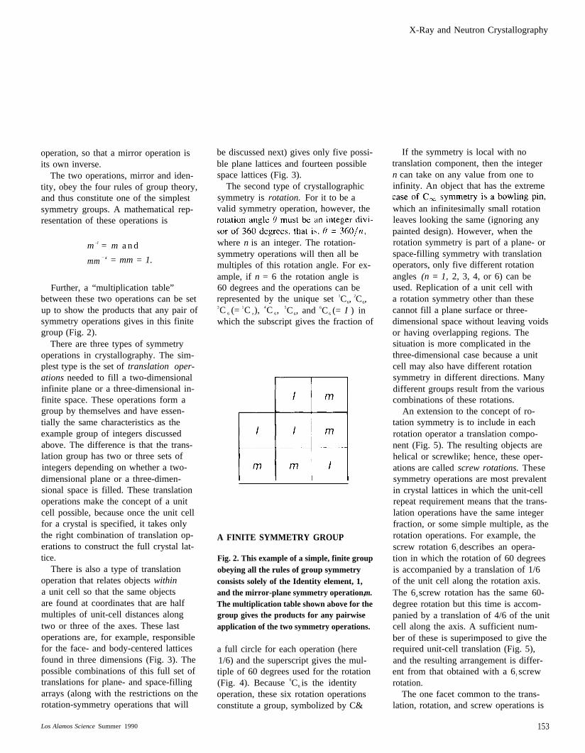
Further, a “multiplication table”between these two operations can be setup to show the products that any pair ofsymmetry operations gives in this finitegroup (Fig. 2).
There are three types of symmetryoperations in crystallography. The sim-plest type is the set of translation oper-ations needed to fill a two-dimensionalinfinite plane or a three-dimensional in-finite space. These operations form agroup by themselves and have essen-tially the same characteristics as theexample group of integers discussedabove. The difference is that the trans-lation group has two or three sets ofintegers depending on whether a two-dimensional plane or a three-dimen-sional space is filled. These translationoperations make the concept of a unitcell possible, because once the unit cellfor a crystal is specified, it takes onlythe right combination of translation op-erations to construct the full crystal lat-tice.
There is also a type of translationoperation that relates objects withina unit cell so that the same objectsare found at coordinates that are halfmultiples of unit-cell distances alongtwo or three of the axes. These lastoperations are, for example, responsiblefor the face- and body-centered latticesfound in three dimensions (Fig. 3). Thepossible combinations of this full set oftranslations for plane- and space-fillingarrays (along with the restrictions on therotation-symmetry operations that will
be discussed next) gives only five possi-ble plane lattices and fourteen possiblespace lattices (Fig. 3).
The second type of crystallographicsymmetry is rotation. For it to be avalid symmetry operation, however, the
where n is an integer. The rotation-symmetry operations will then all bemultiples of this rotation angle. For ex-ample, if n = 6 the rotation angle is60 degrees and the operations can berepresented by the unique set 1C6,
2C6,3C 6 (=
1C z), 4C 6,
5C 6, and 6C 6 (= I ) inwhich the subscript gives the fraction of
A FINITE SYMMETRY GROUP
Fig. 2. This example of a simple, finite groupobeying all the rules of group symmetryconsists solely of the Identity element, 1,and the mirror-plane symmetry operation, m.The multiplication table shown above for thegroup gives the products for any pairwiseapplication of the two symmetry operations.
a full circle for each operation (here1/6) and the superscript gives the mul-tiple of 60 degrees used for the rotation(Fig. 4). Because 6C6 is the identityoperation, these six rotation operationsconstitute a group, symbolized by C&
If the symmetry is local with notranslation component, then the integern can take on any value from one toinfinity. An object that has the extreme
which an infinitesimally small rotationleaves looking the same (ignoring anypainted design). However, when therotation symmetry is part of a plane- orspace-filling symmetry with translationoperators, only five different rotationangles (n = 1, 2, 3, 4, or 6) can beused. Replication of a unit cell witha rotation symmetry other than thesecannot fill a plane surface or three-dimensional space without leaving voidsor having overlapping regions. Thesituation is more complicated in thethree-dimensional case because a unitcell may also have different rotationsymmetry in different directions. Manydifferent groups result from the variouscombinations of these rotations.
An extension to the concept of ro-tation symmetry is to include in eachrotation operator a translation compo-nent (Fig. 5). The resulting objects arehelical or screwlike; hence, these oper-ations are called screw rotations. Thesesymmetry operations are most prevalentin crystal lattices in which the unit-cellrepeat requirement means that the trans-lation operations have the same integerfraction, or some simple multiple, as therotation operations. For example, thescrew rotation 61 describes an opera-tion in which the rotation of 60 degreesis accompanied by a translation of 1/6of the unit cell along the rotation axis.The 64 screw rotation has the same 60-degree rotation but this time is accom-panied by a translation of 4/6 of the unitcell along the axis. A sufficient num-ber of these is superimposed to give therequired unit-cell translation (Fig. 5),and the resulting arrangement is differ-ent from that obtained with a 61 screwrotation.
The one facet common to the trans-lation, rotation, and screw operations is
Los Alamos Science Summer 1990 153
X-Ray and Neutron Crystallography
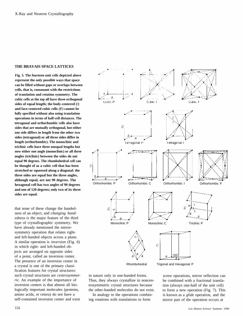
THE BRAVAIS SPACE LATTICES
Fig. 3. The fourteen unit cells depicted aboverepresent the only possible ways that spacecan be filled without gaps or overlaps betweencells, that is, consonant with the restrictionsof translation and rotation symmetry. Thecubic cells at the top all have three orthogonalsides of equal length; the body-centered (/)and face-centered cubic cells (F) cannot befully specified without also using translationoperations in terms of half-cell distances. Thetetragonal and orthorhombic cells also havesides that are mutually orthogonal, but eitherone side differs in length from the other twosides (tetragonal) or all three sides differ inlength (orthorhombic). The monoclinic andtriclinic cells have three unequal lengths butnow either one angle (monoclinic) or all threeangles (triclinic) between the sides do notequal 90 degrees. The rhombohedral cell canbe thought of as a cubic cell that has beenstretched or squeezed along a diagonal: thethree sides are equal but the three angles,although equal, are not 90 degrees. Thehexagonal cell has two angles of 90 degreesand one of 120 degrees; only two of its threesides are equal.
that none of these change the handed-ness of an object, and changing hand-edness is the major feature of the thirdtype of crystallographic symmetry. Wehave already mentioned the mirror-symmetry operation that relates right-and left-handed objects across a plane.A similar operation is inversion (Fig. 6)in which right- and left-handed ob-jects are arranged on opposite sidesof a point, called an inversion center.The presence of an inversion center ina crystal is one of the primary classi-fication features for crystal structures:such crystal structures are centrosymmet-ric. An example of the importance ofinversion centers is that almost all bio-logically important molecules (proteins,amino acids, et cetera) do not have aself-contained inversion center and exist
Orthorhombic P Orthorhombic C Orthorhombic I Orlhorhombic F
Monoclinic P Monoclinic C Triclinic P
Rhombohedral Trigonal and Hexagonal P
in nature only in one-handed forms. screw operations, mirror reflection canThus, they always crystallize in noncen- be combined with a fractional transla-trosymmetric crystal structures because tion (always one-half of the unit cell)the other-handed molecules do not exist. to form a new operation (Fig. 7). This
In analogy to the operations combin- is known as a glide operation, and theing rotations with translations to form mirror part of the operation occurs at
154 Los Alamos Science Summer 1990
X-Ray and Neutron Crystallography
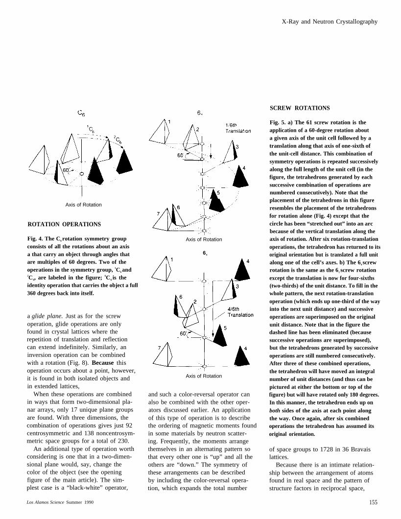
SCREW ROTATIONS
Axis of Rotation
ROTATION OPERATIONS
Fig. 4. The C6 rotation symmetry groupconsists of all the rotations about an axisa that carry an object through angles thatare multiples of 60 degrees. Two of theoperations in the symmetry group, 1C6 and2C6, are labeled in the figure; 6C6 is theidentity operation that carries the object a full360 degrees back into itself.
a glide plane. Just as for the screwoperation, glide operations are onlyfound in crystal lattices where therepetition of translation and reflectioncan extend indefinitely. Similarly, aninversion operation can be combinedwith a rotation (Fig. 8). Because thisoperation occurs about a point, however,it is found in both isolated objects andin extended lattices,
When these operations are combinedin ways that form two-dimensional pla-nar arrays, only 17 unique plane groupsare found. With three dimensions, thecombination of operations gives just 92centrosymmetric and 138 noncentrosym-metric space groups for a total of 230.
An additional type of operation worthconsidering is one that in a two-dimen-sional plane would, say, change thecolor of the object (see the openingfigure of the main article). The sim-plest case is a “black-white” operator,
Axis of Rotation
64
Axis of Rotation
and such a color-reversal operator canalso be combined with the other oper-ators discussed earlier. An applicationof this type of operation is to describethe ordering of magnetic moments foundin some materials by neutron scatter-ing. Frequently, the moments arrangethemselves in an alternating pattern sothat every other one is “up” and all theothers are “down.” The symmetry ofthese arrangements can be describedby including the color-reversal opera-tion, which expands the total number
Fig. 5. a) The 61 screw rotation is theapplication of a 60-degree rotation abouta given axis of the unit cell followed by atranslation along that axis of one-sixth ofthe unit-cell distance. This combination ofsymmetry operations is repeated successivelyalong the full length of the unit cell (in thefigure, the tetrahedrons generated by eachsuccessive combination of operations arenumbered consecutively). Note that theplacement of the tetrahedrons in this figureresembles the placement of the tetrahedronsfor rotation alone (Fig. 4) except that thecircle has been “stretched out” into an arcbecause of the vertical translation along theaxis of rotation. After six rotation-translationoperations, the tetrahedron has returned to itsoriginal orientation but is translated a full unitalong one of the cell’s axes. b) The 64 screwrotation is the same as the 61 screw rotationexcept the translation is now for four-sixths(two-thirds) of the unit distance. To fill in thewhole pattern, the next rotation-translationoperation (which ends up one-third of the wayinto the next unit distance) and successiveoperations are superimposed on the originalunit distance. Note that in the figure thedashed line has been eliminated (becausesuccessive operations are superimposed),but the tetrahedrons generated by successiveoperations are still numbered consecutively.After three of these combined operations,the tetrahedron will have moved an integralnumber of unit distances (and thus can bepictured at either the bottom or top of thefigure) but will have rotated only 180 degrees.In this manner, the tetrahedron ends up onboth sides of the axis at each point alongthe way. Once again, after six combinedoperations the tetrahedron has assumed itsoriginal orientation.
of space groups to 1728 in 36 Bravaislattices.
Because there is an intimate relation-ship between the arrangement of atomsfound in real space and the pattern ofstructure factors in reciprocal space,
Los Alamos Science Summer 1990 155
X-Ray and Neutron Crystallography
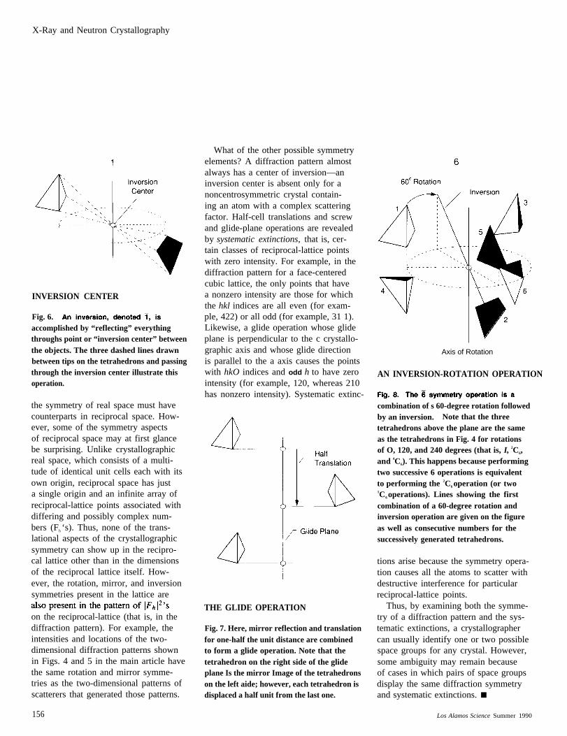
INVERSION CENTER
Fig. 6.accomplished by “reflecting” everythingthroughs point or “inversion center” betweenthe objects. The three dashed lines drawnbetween tips on the tetrahedrons and passingthrough the inversion center illustrate thisoperation.
the symmetry of real space must havecounterparts in reciprocal space. How-ever, some of the symmetry aspectsof reciprocal space may at first glancebe surprising. Unlike crystallographicreal space, which consists of a multi-tude of identical unit cells each with itsown origin, reciprocal space has justa single origin and an infinite array ofreciprocal-lattice points associated withdiffering and possibly complex num-bers (Fh ‘s). Thus, none of the trans-lational aspects of the crystallographicsymmetry can show up in the recipro-cal lattice other than in the dimensionsof the reciprocal lattice itself. How-ever, the rotation, mirror, and inversionsymmetries present in the lattice are
on the reciprocal-lattice (that is, in thediffraction pattern). For example, theintensities and locations of the two-dimensional diffraction patterns shownin Figs. 4 and 5 in the main article havethe same rotation and mirror symme-tries as the two-dimensional patterns ofscatterers that generated those patterns.
What of the other possible symmetryelements? A diffraction pattern almostalways has a center of inversion—aninversion center is absent only for anoncentrosymmetric crystal contain-ing an atom with a complex scatteringfactor. Half-cell translations and screwand glide-plane operations are revealedby systematic extinctions, that is, cer-tain classes of reciprocal-lattice pointswith zero intensity. For example, in thediffraction pattern for a face-centeredcubic lattice, the only points that havea nonzero intensity are those for whichthe hkl indices are all even (for exam-ple, 422) or all odd (for example, 31 1).Likewise, a glide operation whose glideplane is perpendicular to the c crystallo-graphic axis and whose glide directionis parallel to the a axis causes the pointswith hkO indices and odd h to have zerointensity (for example, 120, whereas 210has nonzero intensity). Systematic extinc-
THE GLIDE OPERATION
Fig. 7. Here, mirror reflection and translationfor one-half the unit distance are combinedto form a glide operation. Note that thetetrahedron on the right side of the glideplane Is the mirror Image of the tetrahedronson the left aide; however, each tetrahedron isdisplaced a half unit from the last one.
Axis of Rotation
AN INVERSION-ROTATION OPERATION
combination of s 60-degree rotation followedby an inversion. Note that the threetetrahedrons above the plane are the sameas the tetrahedrons in Fig. 4 for rotationsof O, 120, and 240 degrees (that is, I, 2C6,and 4C6). This happens because performingtwo successive 6 operations is equivalentto performing the 2C6 operation (or two1C6 operations). Lines showing the firstcombination of a 60-degree rotation andinversion operation are given on the figureas well as consecutive numbers for thesuccessively generated tetrahedrons.
tions arise because the symmetry opera-tion causes all the atoms to scatter withdestructive interference for particularreciprocal-lattice points.
Thus, by examining both the symme-try of a diffraction pattern and the sys-tematic extinctions, a crystallographercan usually identify one or two possiblespace groups for any crystal. However,some ambiguity may remain becauseof cases in which pairs of space groupsdisplay the same diffraction symmetryand systematic extinctions. ■
156 Los Alamos Science Summer 1990
X-Ray and Neutron Crystallography
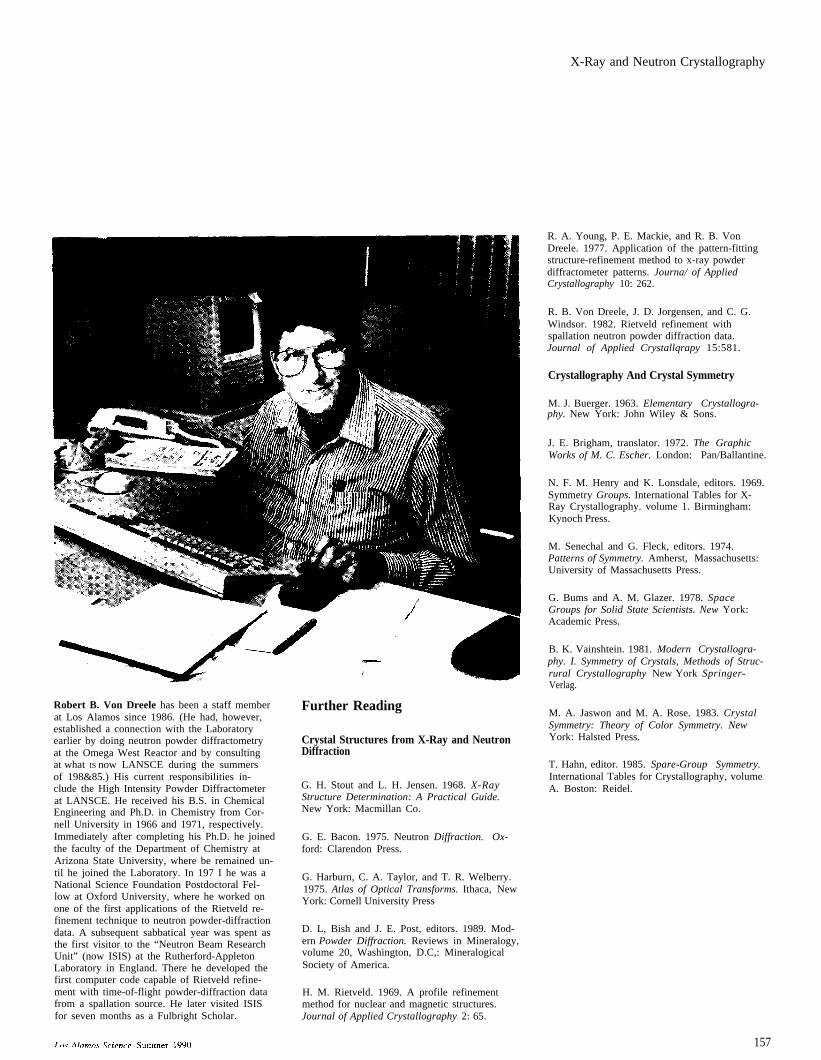
Robert B. Von Dreele has been a staff memberat Los Alamos since 1986. (He had, however,established a connection with the Laboratoryearlier by doing neutron powder diffractometryat the Omega West Reactor and by consultingat what IS now LANSCE during the summersof 198&85.) His current responsibilities in-clude the High Intensity Powder Diffractometerat LANSCE. He received his B.S. in ChemicalEngineering and Ph.D. in Chemistry from Cor-nell University in 1966 and 1971, respectively.Immediately after completing his Ph.D. he joinedthe faculty of the Department of Chemistry atArizona State University, where be remained un-til he joined the Laboratory. In 197 I he was aNational Science Foundation Postdoctoral Fel-low at Oxford University, where he worked onone of the first applications of the Rietveld re-finement technique to neutron powder-diffractiondata. A subsequent sabbatical year was spent asthe first visitor to the “Neutron Beam ResearchUnit” (now ISIS) at the Rutherford-AppletonLaboratory in England. There he developed thefirst computer code capable of Rietveld refine-ment with time-of-flight powder-diffraction datafrom a spallation source. He later visited ISISfor seven months as a Fulbright Scholar.
Further Reading
Crystal Structures from X-Ray and NeutronDiffraction
G. H. Stout and L. H. Jensen. 1968. X-RayStructure Determination: A Practical Guide.New York: Macmillan Co.
G. E. Bacon. 1975. Neutron Diffraction. Ox-ford: Clarendon Press.
G. Harburn, C. A. Taylor, and T. R. Welberry.1975. Atlas of Optical Transforms. Ithaca, NewYork: Cornell University Press
D. L, Bish and J. E. Post, editors. 1989. Mod-ern Powder Diffraction. Reviews in Mineralogy,volume 20, Washington, D.C,: MineralogicalSociety of America.
H. M. Rietveld. 1969. A profile refinementmethod for nuclear and magnetic structures.Journal of Applied Crystallography 2: 65.
R. A. Young, P. E. Mackie, and R. B. VonDreele. 1977. Application of the pattern-fittingstructure-refinement method to x-ray powderdiffractometer patterns. Journa/ of AppliedCrystallography 10: 262.
R. B. Von Dreele, J. D. Jorgensen, and C. G.Windsor. 1982. Rietveld refinement withspallation neutron powder diffraction data.Journal of Applied Crystallqrapy 15:581.
Crystallography And Crystal Symmetry
M. J. Buerger. 1963. Elementary Crystallogra-phy. New York: John Wiley & Sons.
J. E. Brigham, translator. 1972. The GraphicWorks of M. C. Escher. London: Pan/Ballantine.
N. F. M. Henry and K. Lonsdale, editors. 1969.Symmetry Groups. International Tables for X-Ray Crystallography. volume 1. Birmingham:Kynoch Press.
M. Senechal and G. Fleck, editors. 1974.Patterns of Symmetry. Amherst, Massachusetts:University of Massachusetts Press.
G. Bums and A. M. Glazer. 1978. SpaceGroups for Solid State Scientists. New York:Academic Press.
B. K. Vainshtein. 1981. Modern Crystallogra-phy. I. Symmetry of Crystals, Methods of Struc-rural Crystallography New York Springer-Verlag.
M. A. Jaswon and M. A. Rose. 1983. CrystalSymmetry: Theory of Color Symmetry. NewYork: Halsted Press.
T. Hahn, editor. 1985. Spare-Group Symmetry.International Tables for Crystallography, volumeA. Boston: Reidel.
157