zone substations asset management plan - tn047 - zone... · hobart area and are supplied by...
TRANSCRIPT

Asset Management Plan
Zone Substations
Record Number: R302880
Version Number: 2.0
Date: October 2015

Zone Substations Asset Management Plan
Page 2 of 36
Authorisations
Action Name and title Date
Prepared by Greg Hall – Senior Asset Engineer, Asset Strategy 15/09/2015
Reviewed by Santosh Dhakal – Substations Engineer, Asset Engineering
David Ellis –Asset Strategy Team Leader, Asset Strategy
21/09/2015
05/20/2015
Authorised by Nicole Eastoe – Asset Strategy & Performance Leader, Strategic Asset Management
06/10/2015
Review cycle 2.5 Years
Responsibilities This document is the responsibility of the Asset Strategy Team, Tasmanian Networks Pty Ltd, ABN 24 167 357 299 (hereafter referred to as "TasNetworks").
Please contact the Asset Strategy Team Leader with any queries or suggestions.
Implementation All TasNetworks staff and contractors.
Compliance All group managers.
© Tasmanian Networks Pty Ltd 2015
Disclaimer UNCONTROLLED WHEN PRINTED
This document has been prepared and made available solely for information purposes. Whist care was taken in the preparation of the information in this document, and it is provided in good faith, TasNetworks make no representation or warranty (express or implied) as to the accuracy, reliability, or completeness of the information contained in this document, or its suitability for any intended purpose.
TasNetworks (which for the purposes of this disclaimer, includes all their related bodies corporate, officers, employees, contractors, agents and consultants, and those of their bodies corporate) shall have no liability for any loss or damage (including without limitation, liability to any person by reason of negligence or negligent misstatement) for any statements, opinions, information or matter (expressed or implied) arising out of, contained in, or derived from, or for any omissions from, the information in this document, except to the extent that liability under any applicable statute cannot be excluded.
In all cases, anyone proposing to rely on or use the information in this document should independently verify and check the accuracy, completeness, reliability and suitability of that information and the reports and other information relied on by TasNetworks in preparing this document, and should obtain independent and specific advice from appropriate experts or other sources.

Zone Substations Asset Management Plan
Page 3 of 36
Record of revisions
Section number Details

Zone Substations Asset Management Plan
Page 4 of 36
Table of Contents Authorisations ...................................................................................................................................... 2
Responsibilities .................................................................................................................................... 2
Disclaimer ............................................................................................................................................. 2
Record of revisions ............................................................................................................................... 3
1 Purpose............................................................................................................................................. 6
2 Scope ................................................................................................................................................ 6
3 Strategic alignment and objectives .................................................................................................. 6
4 Asset support systems...................................................................................................................... 8
4.1 Systems .................................................................................................................................. 8
4.2 Asset information .................................................................................................................. 8
5 Asset description .............................................................................................................................. 8
5.1 Substation site ..................................................................................................................... 10
5.2 Transformers ........................................................................................................................ 10
5.3 High voltage switchgear ....................................................................................................... 12
5.4 Ancillary systems .................................................................................................................. 13
5.5 Asset type age profile .......................................................................................................... 13
6 Associated risk ................................................................................................................................ 16
6.1 Asset risks ............................................................................................................................ 16
6.1.1 Condition of assets ..................................................................................................... 16
6.1.2 Criticality of asset ....................................................................................................... 18
6.1.3 Probability of failure ................................................................................................... 18
6.1.4 Consequence of Failure .............................................................................................. 18
7 Management plan .......................................................................................................................... 19
7.1 Historical .............................................................................................................................. 19
7.2 Strategy ................................................................................................................................ 20
7.2.1 Routine maintenance ................................................................................................. 21
7.2.2 Routine maintenance versus non‐routine maintenance ........................................... 21
7.2.3 Refurbishment ............................................................................................................ 21
7.2.4 Planned asset replacement versus reactive asset replacement ................................ 22
7.2.5 Non network solutions ............................................................................................... 22
7.2.6 Network augmentation impacts ................................................................................ 22
7.3 Routine maintenance ........................................................................................................... 22
7.3.1 Asset inspection (Visual, load check and condition monitoring) (AIZSM) ................. 22
7.3.2 Zone substation routine maintenance (RMZSR) ........................................................ 24

Zone Substations Asset Management Plan
Page 5 of 36
7.4 Non routine maintenance (ARZSR) ...................................................................................... 27
7.4.1 Minor and major asset repairs ................................................................................... 27
7.5 Asset refurbishment/replacement ...................................................................................... 28
7.5.1 Oil‐filled circuit breakers (REUZS) .............................................................................. 28
7.5.2 Replace urban zone transformers (REUZT) ................................................................ 28
7.5.3 Replace rural zone transformers (RERZT) .................................................................. 29
7.6 Regulatory obligations (REUZQ) .......................................................................................... 29
7.6.1 Repair/Replace fire and exit doors ............................................................................. 30
7.6.2 Emergency and exit lighting ....................................................................................... 30
7.7 Investment evaluation ......................................................................................................... 30
7.8 Spares management ............................................................................................................ 30
7.9 Disposal plan ........................................................................................................................ 30
7.10 Summary of programs ......................................................................................................... 31
8 Financial summary ......................................................................................................................... 32
8.1 Proposed OPEX expenditure plan ........................................................................................ 32
8.2 Proposed CAPEX Expenditure Plan ...................................................................................... 33
8.2.1 CAPEX – OPEX trade offs ............................................................................................ 34
9 Responsibilities ............................................................................................................................... 34
10 Related standards and documentation ......................................................................................... 35
11 Appendix A – Summary of programs and risk ............................................................................... 36

Zone Substations Asset Management Plan
Page 6 of 36
1 Purpose The purpose of this management plan is to define the management strategy for Zone Substations. The plan provides:
TasNetworks’ approach to asset management, as reflected through its legislative and regulatory obligations and strategic plans
The key projects and programs underpinning its activities
Forecast CAPEX and OPEX, including the basis upon which these forecasts are derived
2 Scope This asset management plan covers both urban and rural zone substations and all assets within the substations, with the exception of the secondary systems.
Secondary assets are covered by the Protection and Control Management Plan.
3 Strategic alignment and objectives This asset management plan has been developed to align with both TasNetworks’ Asset Management Policy and Strategic Objectives.
The asset management policy, contained within the Strategic Asset Management Plan, states ‘Consistent with our vision and purpose, we strive for excellence in asset management and are committed to providing a safe working environment, value for our customers, sustainable shareholder outcomes, care for our assets and the environment, safe and reliable network services, whilst effectively and efficiently managing our assets throughout their life‐cycle’.
It is part of a suite of documentation that supports the achievement of TasNetworks strategic performance objectives and, in turn, its mission. The asset management plans identifies the issues and strategies relating to network system assets and detail the specific activities that need to be undertaken to address the identified issues.
Table 1 represents TasNetworks’ documents that support the asset management framework. The diagram highlights the existence of, and interdependence between, the Plan, Do, Check, Act components of good asset management practice.

Zone Substations Asset Management Plan
Page 7 of 36
Figure 1 – TasNetworks asset management documentation framework

Zone Substations Asset Management Plan
Page 8 of 36
The asset management objectives focus on six key areas:
Zero Harm will continue to be our top priority and we will ensure that our safety performance continues to improve.
Cost performance will be improved through prioritisation and efficiency improvements that enable us provide predictable and lowest sustainable pricing to our customers.
Service performance will be maintained at current overall network service levels, whilst service to poorly performing reliability communities will be improved to meet regulatory requirements.
Customer engagement will be improved to ensure that we understand customer needs, and incorporate these into our decision making to maximise value to them.
Our program of work will be developed and delivered on time and within budget.
Our asset management capability will be continually improved to support our cost and service performance, and efficiency improvements.
4 Asset support systems
4.1 Systems TasNetworks utilises asset management information systems to manage its asset information. These systems are maintained to contain up to date, detailed information with regard to the zone substation sites.
The asset information related to the zone substation is managed using a spatial data warehouse (G/Tech). This data base stores critical attributes for each site, including the site location and its interconnection to the network.
A works management system (WASP) is used to manage asset management activities and for the recording of asset performance.
4.2 Asset information Asset related information is stored and accessed through the asset management systems. Where asset information is insufficient, audits are undertaken to gather the required information.
5 Asset description The major sub‐components of the zone substations are:
Substation site: the enclosure, switchyard, building security system and earthing system.
Power transformers: used to step up or down voltage
High voltage switchgear: that provides isolation, disconnection and connection of the sub‐transmission and distribution systems in order to maintain supply to the customer
Ancillary systems: station services supply and low voltage electrical reticulation within the site
The following assets are excluded from the asset class:
Incoming feeders, both overhead and underground
Outgoing feeders, both overhead and underground
Secondary systems
Mobile generators for emergency purposes

Zone Substations Asset Management Plan
Page 9 of 36
Zone substations are established where significant bulk load points exist and there is a need to further distribute the capacity requirements of customer loads at high voltage (HV). This type of asset class forms a key component in the distribution system and requires close monitoring and regular maintenance.
Zone substations contain power transformers, switchgear, earthing systems, protection and control devices, with all infrastructure contained in purpose built enclosures for security and the prevention of unauthorised access.
The zone substations range in size (connected MVA) from 2 MVA to 90 MVA with outgoing high voltage feeders ranging from only one feeder up to sixteen feeders.
As of March 2015, there are seventeen zone substations within the distribution system. These substations are grouped into twelve urban zone substations and five rural zone substations. Trial Harbour Zone whilst in a rural location is similar to that of an urban zone substation in design and so included in urban zone classification. Tables 1 and 2 provide a summary of the urban and rural zones across the network.
Table 1: Urban zone substations
* Capacity for 10 feeders
Table 2: Rural zone substations
Substation Rating(MVA) Number of power transformers
Number of HV outgoing feeders
Year of Construction
Gretna 2 2 2 1962
New Norfolk 10 4 3 1960
Richmond 5 2 3 1960
Tod’s Corner 6 2 1 1971
Wayatinah 2 1 2 2014
Substation Rating(MVA) Number of power
transformers
Number of HV outgoing feeders
Year of construction
Bellerive 45 2 6 1971
Cambridge 40 2 12 2008
Claremont 45 2 10 1969
Derwent Park 45 2 10 1964
East Hobart 90 3 12 2004
Geilston Bay 45 2 8 1964
Howrah 50 2 6* 2011
New Town 45 2 8 1966
Sandy Bay 90 3 13 1967
Summerleas 25 1 5* 2014
West Hobart 90 3 14 2001
Trial Harbour 40 2 3 2007

Zone Substations Asset Management Plan
Page 10 of 36
The urban zone substations, with the exception of Trial Harbour, are located within the greater Hobart area and are supplied by dedicated sub‐transmission feeders. These substations take supply at a voltage of 33 kV and step these voltages down to a distribution voltage of 11 kV. Prior to a major redevelopment in 2003 in the Hobart area the substations were supplied at either 22kV or 33kV.
Trial Harbour Zone is located on the west coast of Tasmania near Zeehan. It is supplied at 44kV and steps the voltage down to a distribution voltage of 22 kV.
The rural zone substations are located throughout rural areas and are also supplied from rural distribution feeders. These feeders also supply customer loads.
The rural zone substations take supply at a voltage of 22 kV and step down the voltage to the local distribution voltage of 11kV, with the exception of the Wayatinah zone substation, which steps the voltage up from 11 kV to 22 kV, and Tod’s Corner zone substation, which steps up the voltage from 6.6 kV to 22 kV.
5.1 Substation site Security and prevention of unauthorised access to a highly dangerous area is of paramount concern with zone substations, especially when located close to populated areas.
Zone substation enclosures are purpose‐built for each zone substation and may be a building, fence or combination of the two. The enclosures are designed for safety and security and, in the case of building‐types, to provide a weatherproof environment for the equipment.
These enclosures may also provide noise mitigation and provide a more aesthetically pleasing site to meet local requirements.
All zone substations contain an earthing system. The earthing system is designed to ensure that under fault conditions people are not exposed to hazardous voltage by providing a low impedance return path for fault current. Earthing systems are made of a conductive grid, typically copper and buried below ground level. All non‐energised conductive material in the substation is bonded to the earthing system.
The integrity of the earthing system is paramount for maintaining operational personnel and public safety and for correct operation of protection equipment. The fault level, fault clearing time and site conditions dictate the extent of earthing system required.
5.2 Transformers The power transformers at the zone substations step the supply voltage down to the required high voltage for the distribution feeders. The transformers at the urban zones have a nominal voltage ratio of 33 kV to 11 kV and range in size from 20 to 30 MVA.
The power transformers at the rural zones are significantly smaller and range in size from 1 to 3 MVA and comprise a variety of voltage ratios.

Zone Substations Asset Management Plan
Page 11 of 36
Table 3: Urban zone substations power transformers
Substation Designation Voltage Ratio
(kV/kV) Manufacturer Rating(MVA)
Year of Manufacture
Bellerive T1 33/11 Wilson 15/22.5 1970
Bellerive T2 33/11 Wilson 15/22.5 1970
Cambridge T1 33/11 Wilson 15/20 2008
Cambridge T2 33/11 Wilson 15/20 2008
Claremont T1 33/11 Wilson 15/22.5 1964
Claremont T2 33/11 Wilson 15/22.5 1964
Derwent Park T1 33/11 Wilson 15/22.5 1964
Derwent Park T2 33/11 Wilson 15/22.5 1964
East Hobart T1 33/11 ALSTOM 20/30 2004
East Hobart T2 33/11 ALSTOM 20/30 2004
East Hobart T3 33/11 ALSTOM 20/30 2004
Geilston Bay T1 33/11 Wilson 15/22.5 1968
Geilston Bay T2 33/11 Wilson 15/22.5 1968
Howrah T1 33/11 ALSTOM 15/25 2011
Howrah T2 33/11 ALSTOM 15/25 2011
New Town T1 33/11 AREVA 15/22.5 2005
New Town T2 33/11 ALSTOM 15/22.5 1999
Sandy Bay T1 33/11 ALSTOM 20/30 2004
Sandy Bay T2 33/11 ALSTOM 20/30 2004
Sandy Bay T3 33/11 ALSTOM 20/30 2004
Sandy Bay T4 33/11 Wilson 15/22.5 1967
Summerleas T1 33/11 ALSTOM 15/25 2011
West Hobart T1 33/11 ALSTOM 20/30 2001
West Hobart T2 33/11 ALSTOM 20/30 2001
West Hobart T3 33/11 ALSTOM 20/30 2001
Trial Harbour T1 66/44/22 AREVA 22.5/30 at 66kV 15/20 at 44kV
2007
Trial Harbour T2 66/44/22kV AREVA 22.5/30 at 66 kV
and 15/20 at44kV
2007
Zone Substations Asset Management Plan
Page 12 of 36
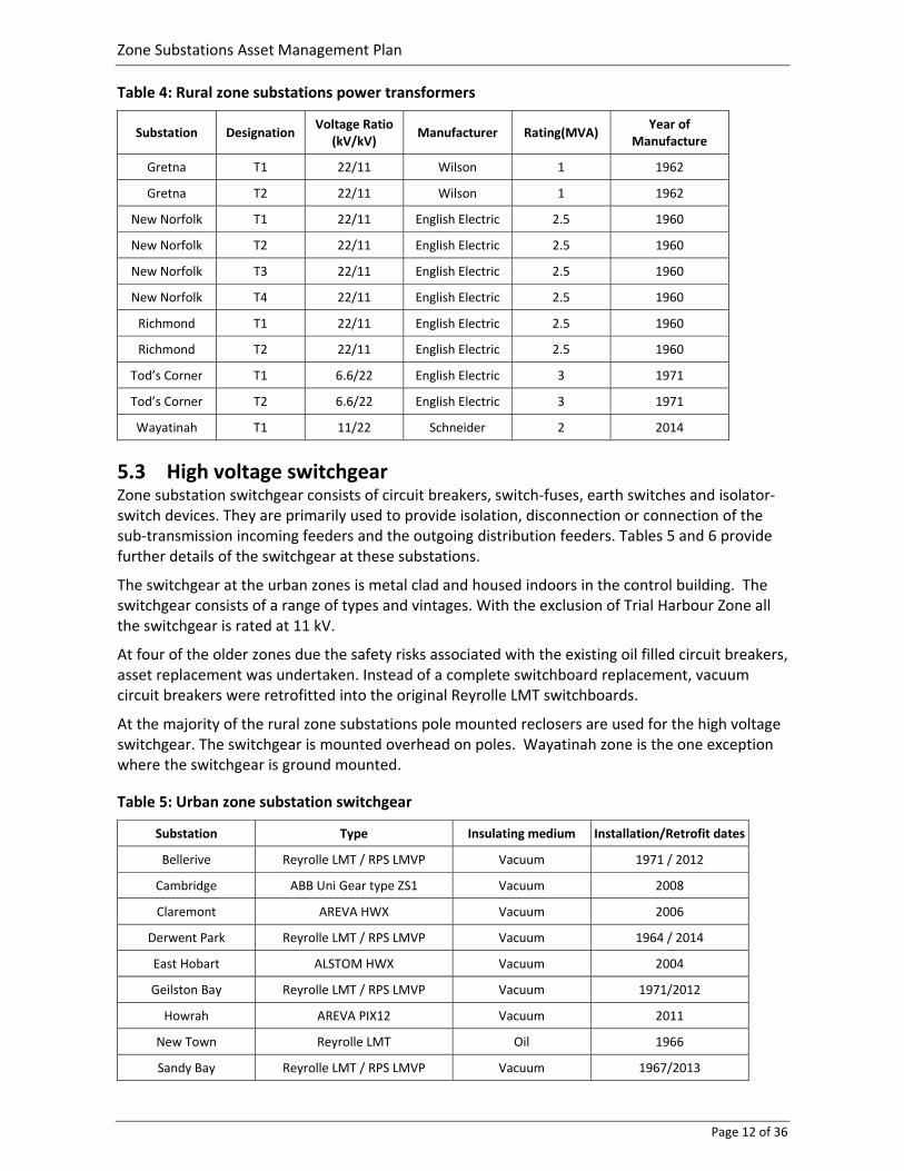
Table 4: Rural zone substations power transformers
Substation Designation Voltage Ratio
(kV/kV) Manufacturer Rating(MVA)
Year of Manufacture
Gretna T1 22/11 Wilson 1 1962
Gretna T2 22/11 Wilson 1 1962
New Norfolk T1 22/11 English Electric 2.5 1960
New Norfolk T2 22/11 English Electric 2.5 1960
New Norfolk T3 22/11 English Electric 2.5 1960
New Norfolk T4 22/11 English Electric 2.5 1960
Richmond T1 22/11 English Electric 2.5 1960
Richmond T2 22/11 English Electric 2.5 1960
Tod’s Corner T1 6.6/22 English Electric 3 1971
Tod’s Corner T2 6.6/22 English Electric 3 1971
Wayatinah T1 11/22 Schneider 2 2014
5.3 High voltage switchgear Zone substation switchgear consists of circuit breakers, switch‐fuses, earth switches and isolator‐switch devices. They are primarily used to provide isolation, disconnection or connection of the sub‐transmission incoming feeders and the outgoing distribution feeders. Tables 5 and 6 provide further details of the switchgear at these substations.
The switchgear at the urban zones is metal clad and housed indoors in the control building. The switchgear consists of a range of types and vintages. With the exclusion of Trial Harbour Zone all the switchgear is rated at 11 kV.
At four of the older zones due the safety risks associated with the existing oil filled circuit breakers, asset replacement was undertaken. Instead of a complete switchboard replacement, vacuum circuit breakers were retrofitted into the original Reyrolle LMT switchboards.
At the majority of the rural zone substations pole mounted reclosers are used for the high voltage switchgear. The switchgear is mounted overhead on poles. Wayatinah zone is the one exception where the switchgear is ground mounted.
Table 5: Urban zone substation switchgear
Substation Type Insulating medium Installation/Retrofit dates
Bellerive Reyrolle LMT / RPS LMVP Vacuum 1971 / 2012
Cambridge ABB Uni Gear type ZS1 Vacuum 2008
Claremont AREVA HWX Vacuum 2006
Derwent Park Reyrolle LMT / RPS LMVP Vacuum 1964 / 2014
East Hobart ALSTOM HWX Vacuum 2004
Geilston Bay Reyrolle LMT / RPS LMVP Vacuum 1971/2012
Howrah AREVA PIX12 Vacuum 2011
New Town Reyrolle LMT Oil 1966
Sandy Bay Reyrolle LMT / RPS LMVP Vacuum 1967/2013
Zone Substations Asset Management Plan
Page 13 of 36
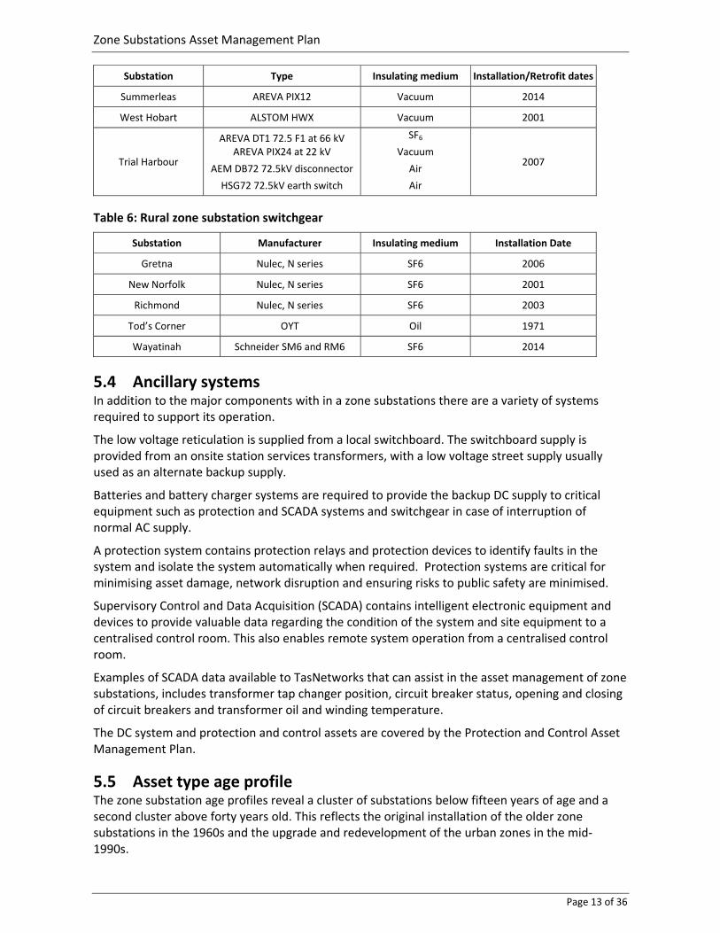
Substation Type Insulating medium Installation/Retrofit dates
Summerleas AREVA PIX12 Vacuum 2014
West Hobart ALSTOM HWX Vacuum 2001
Trial Harbour
AREVA DT1 72.5 F1 at 66 kV AREVA PIX24 at 22 kV
AEM DB72 72.5kV disconnector
HSG72 72.5kV earth switch
SF6
Vacuum
Air
Air
2007
Table 6: Rural zone substation switchgear
Substation Manufacturer Insulating medium Installation Date
Gretna Nulec, N series SF6 2006
New Norfolk Nulec, N series SF6 2001
Richmond Nulec, N series SF6 2003
Tod’s Corner OYT Oil 1971
Wayatinah Schneider SM6 and RM6 SF6 2014
5.4 Ancillary systems In addition to the major components with in a zone substations there are a variety of systems required to support its operation.
The low voltage reticulation is supplied from a local switchboard. The switchboard supply is provided from an onsite station services transformers, with a low voltage street supply usually used as an alternate backup supply.
Batteries and battery charger systems are required to provide the backup DC supply to critical equipment such as protection and SCADA systems and switchgear in case of interruption of normal AC supply.
A protection system contains protection relays and protection devices to identify faults in the system and isolate the system automatically when required. Protection systems are critical for minimising asset damage, network disruption and ensuring risks to public safety are minimised.
Supervisory Control and Data Acquisition (SCADA) contains intelligent electronic equipment and devices to provide valuable data regarding the condition of the system and site equipment to a centralised control room. This also enables remote system operation from a centralised control room.
Examples of SCADA data available to TasNetworks that can assist in the asset management of zone substations, includes transformer tap changer position, circuit breaker status, opening and closing of circuit breakers and transformer oil and winding temperature.
The DC system and protection and control assets are covered by the Protection and Control Asset Management Plan.
5.5 Asset type age profile The zone substation age profiles reveal a cluster of substations below fifteen years of age and a second cluster above forty years old. This reflects the original installation of the older zone substations in the 1960s and the upgrade and redevelopment of the urban zones in the mid‐1990s.

Zone Substations Asset Management Plan
Page 14 of 36
Figure 2 – Urban zone substation age profile
Figure 3 – Urban zone substation age profile
The urban zone substation transformer age profile is provided in figure 4. The age profile is similar to that of the urban zone substation age profile, with two notable age groups i.e. a group of eight transformers in the 44 to 51 year age bracket and a second much younger group of eighteen transformers in the 2 to 16 year age bracket.
0
10
20
30
40
50
60Age (years)
0
10
20
30
40
50
60
New Norfolk Richmond Gretna Tod’s Corner Wayatinah
Age (Years)

Zone Substations Asset Management Plan
Page 15 of 36
Figure 4 – Urban zone substation transformer age profile
The rural zone substation transformer age profile is provided in figure 5. With the exception of Wayatinah Zone which has undergone a recent redevelopment, the majority of the transformers at the rural zones are in excess of 50 years of age.
Figure 5 – Rural zone substation transformer age profile
0
10
20
30
40
50
60
Derwen
t Park T1
Derwen
t Park T2
Geilston Bay T1
Geilston Bay T2
Claremont T1
Claremont T2
Bellerive T1
Bellerive T2
New
Town T2
West Hobart T1
West Hobart T2
West Hobart T3
East Hobart T1
East Hobart T2
East Hobart T3
Sandy Bay T1
Sandy Bay T2
Sandy Bay T3
New
Town T1
Trial H
arbour T1
Trial H
arbour T2
Cam
bridge T1
Cam
bridge T2
Howrah T1
Howrah T2
Summerleas T1
Age (Years)
Transformer
0
10
20
30
40
50
60
Age (Years)
Transformer

Zone Substations Asset Management Plan
Page 16 of 36
6 Associated risk An assessment of the risks associated with zone substations has been made in accordance with TasNetworks’ risk management framework. For each asset in this class a detailed assessment has been made based on:
Condition of zone substation and its critical assets
Criticality of zone substation and associated assets
Probability of failure (not meeting business requirement)
Consequence of failure
‐ Performance
‐ Safety
‐ Environment
‐ Customer
Based on this assessment a need has been identified to actively manage these to ensure that their performance meets business requirements and the associated risks are maintained at a acceptable level.
6.1 Asset risks
6.1.1 Condition of assets
6.1.1.1 Sites Periodic inspections and routine maintenance of the zone substation sites has ensured that the substations sites i.e. external fences, buildings and switchyards are in sound condition and secure from unauthorised entry.
With the exception of Trial Harbour, the elimination of live electrical equipment within the urban zone switchyards greatly reduces the safety risks to personnel within the yard. Unlike the urban zones, the rural zones do contain live and exposed electrical equipment. In some instances the installations are not compliant with current standards. This risk is managed through training, administrative controls and the use of personal protective equipment.
At all sites signage is provided to notify people of the hazards that exist within the sites.
6.1.1.2 Switchgear Periodic inspections and routine maintenance programs indicate that the switchgear and enclosures are in good condition.
The urban zones contain a variety of switchgear types and ages. At four of the older sites that originally contained Reyrolle LMT oil filled circuit breakers, the oil filled circuit breakers have been retrofitted with modern vacuum circuit breakers. Arc fault capability has also been added to reduce the risk to operational personnel. Although this upgrade greatly reduces the reliability of the switchgear and also reduces the safety risk, as the original switchboard has been retained, including some critical components e.g. current and voltage transformers, some additional asset replacement will be required at these sites in the next 5 to 10 years.

Zone Substations Asset Management Plan
Page 17 of 36
6.1.1.3 Transformers Condition monitoring of the urban zone transformers has shown the urban zone transformers to be in a satisfactory condition, although some deterioration is evident in some of the older transformers.
Condition monitoring of the rural zone transformers has indicated notable deterioration in some of the transformers. The poor condition may result in a service failure occurring with notable customer supply disruptions to the surrounding area. The rural transformer condition is summarised in table 7.
Table 7: Rural zone substation – transformer oil condition
Site Condition
Gretna ‐ The acidity and interfacial tension indicates poor oil quality i.e. deterioration of the insulating oil.
‐ Increased furan levels indicating cellulose is in deteriorating condition.
‐ Asset replacement is planned for 2016/2017
New Norfolk ‐ Transformers T1, T2, T3 and T4 have high moisture levels and have high acidity indicating poor oil quality i.e. deterioration of the insulating oil.
‐ Increased furan levels indicate the cellulose is in a deteriorated condition
‐ Asset replacement is planned for 2018/19
Richmond ‐ Transformers T1 and T2 have high moisture levels
‐ T2 has high acidity indicating poor oil quality i.e. deterioration of the insulating oil
‐ Increased furan levels indicate the cellulose is in a deteriorated condition
‐ Replacement proposed in 2016/2017 (Reference 9)
Tod’s Corner ‐ Transformers T2 and T3 have high moisture levels
6.1.1.4 Asbestos TasNetworks is required to comply with Work Health and Safety Act and Regulations 2012 and the Workplace Standards Tasmania: How to Manage and Control Asbestos in the Workplace Code of Practice 2012 (reference 8 and 13) with regards to the management of sites containing asbestos.
The zone substations constructed prior to 1980 are likely to contain asbestos. These sites include:
Bellerive
Claremont (old buildings only)
Derwent Park
Geilston Bay
New Town
Sandy Bay
Equipment that may contain asbestos includes switchboards, metering panels, roof lining, conduits and doors. An audit was completed in 2013/2014 of these zone substations to determine which equipment contains asbestos. As a result of this audit, labelling of equipment and the completion of a zone substation asbestos register is to be undertaken. This information is used to assist the routine asbestos inspections as detailed in section 7.3.1.5.

Zone Substations Asset Management Plan
Page 18 of 36
6.1.1.5 Confined spaces All confined spaces within substations e.g. cable trenches must comply with the Building Code of Australia (BCA). TasNetworks is required to routinely inspect and maintain these areas in accordance with the requirements of the Code.
To reduce the safety risk presented by these areas, access to them is restricted, with entry only by trained personnel working in accordance with TasNetworks’ confied space work practice.
6.1.1.6 Emergency and exit lighting The emergency and exit lighting within TasNetworks’ substations must comply with the Building Code of Australia (BCA).
TasNetworks is required to routinely inspect and maintain these assets in accordance with the requirements of the Code and AS/NZS 2293.2 Emergency evacuation lighting for buildings – Inspection and maintenance [10].
6.1.1.7 Fire and exit doors Fire and exit doors within TasNetworks’ substations must comply with the Building Code of Australia (BCA). TasNetworks is required to routinely inspect and maintain these assets in accordance with the requirements of the Code and AS 1851 Maintenance of fire protection systems and equipment (Reference 6).
6.1.2 Criticality of asset Zone substations are essential for providing customer supply and network performance, particularly in the greater Hobart area. With zone substations acting as bulk supply points an asset failure or reduction in performance can result in measurable impact to network performance and statistics e.g. SAIDI and SAIFI.
The interconnectivity of the distribution network in the greater Hobart area means that asset failures can sometimes be accommodated with minimal network disruption. This is achieved by reconfiguring the network. Unlike urban zones, with rural zones there is often limited means to provide alternative supplies to them and the network supplied from the zone. For this reason asset failures at rural zones can result in extended network disruptions.
6.1.3 Probability of failure TasNetworks experiences a number of high voltage failures each year due to unprecedented faults, however asset failures with zone substations are not common. The probability of failures for assets within the zone substations is considered to be low and at an acceptable risk level in accordance with TasNetworks’ risk framework.
6.1.4 Consequence of Failure The results of Zone substation failures can be categorised under the following main groups:
Performance on Power Quality
Safety Risk due to loss of oil
Environmental hazards due to oil spills.
Disruption to Customer Supply
Zone Substations Asset Management Plan
Page 19 of 36
7 Management plan
7.1 Historical TasNetworks’ asset management practices for these assets have been stable for a number of years and are generally considered to be providing a well‐balanced trade‐off between maintenance and capital expenditure. In particular, TasNetworks believes the practices of condition based renewal, driven by asset inspection and maintenance practices are enabling the development of sound asset management strategies.
Due to the critical nature of this asset class, frequent maintenance is required to defer unnecessarily early capital expenditure. TasNetworks believes that the existing frequency of maintenance is reasonable and that the practices are capturing the issues appropriately.
Capital expenditure has been low historically due to adequate performance and condition of the equipment, however, this will change going into the future with the deteriorating condition of some of the assets.
Changes to the Occupational Licensing Act 2005 that became effective on the 19 January 2009 have required TasNetworks to be compliant with The Occupational Licencing Code of Practice 2013. This code of practice sets the minimum standards for electrical work in Tasmania.
Incorporated into this Code of Practice is the requirement to comply with:
AS 2067 (Substations and high voltage substations)
AS/NZS 3000 (Wiring Rules)
AS/NZS 7000
Any additional obligations imposed by AS 2067, AS/NZS 3000 and AS/NZS 7000 referring to further Australian Standards or documents, including any amendments or revisions of those Australian Standards or documents from time to time
The Code of Practice requires that any person performing electrical work within Tasmania to comply with these Australian Standards.
These changes have mandated the requirement to comply with the regulatory, contractual and legal responsibilities outlined in section 7.2.1.

Zone Substations Asset Management Plan
Page 20 of 36
7.2 Strategy The four key principles of TasNetworks’ asset management strategy are:
Minimising the cost of supply to the customer to the lowest sustainable level
Maintaining network performance
Managing the business operating risks at an appropriate level
Complying with regulatory, contractual and legal responsibilities
The factors relevant to the management of the zone substation assets that influence each principle are listed in the following sections.
Minimising cost of supply to the customers to the lowest sustainable level:
Ensuring cost effective trade‐offs are made between pro‐active and reactive maintenance
practices
Ensuring all reasonable routine maintenance (as per manufacturer’s recommendations)
precautions are implemented to protect the asset for the duration of its service life
Capturing adequate information on the assets to facilitate informed decision making
Maintaining network performance:
Ensuring contingency procedures (redundant capacity and portable generators) are in
place for any (n‐1) events, as the impact of failures is significant and exact failure is difficult
to predict even after frequent condition monitoring
Ensuring appropriate spares are maintained as the lead‐time for some of the assets
(specifically transformers) is very long
By identifying trends in asset performance to target future likely failures
Managing business operating risks at an appropriate level:
Ensuring adequate fencing and protection of building enclosures at all zone substations to
comply with legislation and ensure public safety as these sites contain dangerous voltages
in areas generally frequented by the public
Failure of transformers and switchgear can cause explosive failure and needs to be avoided
where practical
Ensuring all equipment is suitably secured and earthed
Ensuring adequate monitoring and inspection activities cover legislative compliance
obligations and duty of care safety obligations
Ensuring all risks are identified and have adequate management plans integrated into the
business’ practices
Ensure adequate monitoring and inspection activities cover regulatory, contractual and
legislative compliance requirements and duty of care safety obligations

Zone Substations Asset Management Plan
Page 21 of 36
Complying with regulatory, contractual and legal responsibilities:
Ensure adequate monitoring and inspection activities cover regulatory, contractual and legislative compliance requirements and duty of care safety obligations.
Some of the identified compliance requirements are detailed below:
Ensuring oil (with or without Polychlorinated Biphenyl (PCB)) spill risks are managed in
compliance with TasNetworks’ Health, Safety, Sustainability and Environment policy
(reference Error! Reference source not found.)
Ensuring confined space entry signage and records are in accordance to AS 2865: 2009, Confined Spaces and Work, Health and Safety Regulations 2012
Ensuring installations of assets (including earthing) are compliant to:
‐ AS 2067: Substation and high voltage installations exceeding 1kV a.c.
‐ AS1940: The storage and handling of flammable and combustible liquids
‐ Electricity Network Association (ENA) guidelines
‐ Building Code of Australia
‐ Protection of Openings C3.5 Doorways in firewalls
‐ Part E1, Fire fighting equipment
‐ Part E2 Smoke Hazard Management generally and in particular, with clause E2.2 and E2.3 regarding air handling, smoke detection and alarm, and special hazards of fire risk
‐ Part E4 Emergency lighting, Exit signs and warning systems
Ensuring inspection and monitoring are compliant to:
‐ AS 1851 Maintenance of fire protection system and equipment
‐ AS/NZS 2293.2 Emergency evacuation lighting for buildings – Inspection and maintenance
‐ Workplace Standards Tasmania: How to Manage and Control Asbestos in the Workplace Code of Practice 2012
7.2.1 Routine maintenance To meet the asset management strategy there is a need to undertake routine maintenance on these assets. Routine maintenance maximise the service life and reliability of the assets and ensures they remain fit for service.
The absence of routine maintenance would result in a reduction in reliability for these assets and an unacceptable safety risk if their condition was not actively managed.
7.2.2 Routine maintenance versus non‐routine maintenance Failures of most of the assets in zone substations have the potential for serious or catastrophic damage to both other zone substation assets and to nearby areas, as well as a substantial impact on reliability. Due to the critical nature of these assets, reactive corrective maintenance is avoided where possible due to the generally high costs involved. Routine maintenance programs represent a cost effective alternative.
7.2.3 Refurbishment Where zone substation primary equipment is removed from the network in good operating condition by drivers such as capacity and power quality drivers, these assets are assessed for redeployment back into the network where it is an economic proposition.

Zone Substations Asset Management Plan
Page 22 of 36
7.2.4 Planned asset replacement versus reactive asset replacement A reactive asset replacement program is not an attractive alternative to planned asset replacement due to the significant supply disruption that would occur if assets were allowed to run to failure. Lead times for replacement zone substation equipment can be significant and in excess of six months, depending on the availability of supply and manufacture, and results in a higher cost than planned asset replacement.
TasNetworks’ urban zone substations supply high density urban, commercial and CBD communities where extended periods of outages are unacceptable. The distribution system has adequate connectivity to reconfigure the network in the event of a zone substation failure, but the extent to which supply can be restored is restricted by the current load on the network. Due to the significant reliability and system security risk that leaving the distribution system in these contingency arrangements for extended periods of time poses, reactive asset replacement is avoided where possible.
The use of temporary mobile generation substations is a possible option for providing network support following asset failures. Leasing arrangements are also in place with external service providers for the supply of additional units if required.
7.2.5 Non network solutions Zone substations are a fundamental requirement of the network with very limited alternatives available for providing the functionality. Network loading and security is usually the driver for the need to install additional zone substations on the network. Demand side management such as smart meters and ripple control serve to defer, but not fully remove the need for investment.
7.2.6 Network augmentation impacts TasNetworks’ requirements for developing the power transmission system are principally driven by five elements:
Demand forecasts
New customer connection requests
New generation requests
Network performance requirements
National electricity rules (NER) compliance
7.3 Routine maintenance
7.3.1 Asset inspection (Visual, load check and condition monitoring) (AIZSM) The asset inspection program has five components:
Visual inspections and load check
Confined space inspections
Oil testing
Thermal inspections
Asbestos inspections
7.3.1.1 Visual inspections and load checks A visual inspection of each zone substation is conducted every three months. The objective of the inspection is to ensure that the condition of the assets and site is sound, and that the site remains

Zone Substations Asset Management Plan
Page 23 of 36
secure. The frequency is based on the manufacturer’s recommendation for the different assets and TasNetworks’ previous experience regarding the site enclosures and signage etc.
TasNetworks monitors load on all the urban zone substations through its SCADA system. Most of the transformers operate well below their full continuous load capacity. This ensures that the total substation load is maintained under the firm capacity of the substation.
Integrity checks of the SCADA systems are conducted every six months in conjunction with the visual inspection at all urban zones.
7.3.1.2 Confined space inspections The aim of the confined space inspections is to ensure that the information contained in the confined space register is correct and all on‐site labelling is in place.
The definition of a confined space is contained in Regulation 5 of the Work Health and Safety Regulations 2012.
An audit was undertaken in 2010 to identify confined spaces within TasNetworks’ sites. The following assets were classified as confined spaces as part of the audit:
The cable trenches in the urban zone substations
The oil containment tanks at the urban zone substations, including Trial Harbour Zone Substation
These inspections are undertaken every four years and are conducted at the same time as the asbestos inspections.
7.3.1.3 Oil testing Regular testing of oil samples from transformers is important to monitor the moisture content of the transformer oil and the dissolved gas content as well to capture any indication of any internal faults, such as partial discharge, overheating or arcing, within the transformer.
The aim of the transformer oil‐testing program is:
Understand ageing and deterioration of the insulating oil and cellulose by analysing number of physical and electrical properties of the oil
Monitor for fault conditions and operational problems in the transformer by performing dissolved gas analysis.
Transformer oil sampling and testing is undertaken annually for the urban zone substation and every two years for the rural zone substation transformers. The practice and frequency are in line with other distribution and transmission network service providers. Where specific issues are identified treatment plans are developed to manage the situation. These plans may include increased monitoring or remedial work to prevent a failure occurring.
The testing and analysis of oil samples is undertaken by an external NATA certified laboratory.
7.3.1.4 Thermal inspections The aim of the thermal inspections is to inspect all accessible equipment to detect any hot spots, which may be an indicator of a developing failure.
Thermal inspections are conducted once every two years at each rural zone substation site.
More frequent thermal inspections may be required at particular sites in the event of abnormal test results.
This work is conducted at the same time as the partial discharge testing routine.

Zone Substations Asset Management Plan
Page 24 of 36
7.3.1.5 Asbestos inspections To address the issues associated with asbestos (Refer Section 6.1.1) TasNetworks has a program of asbestos inspections.
The aim of periodic asbestos inspections is to ensure that the information in TasNetworks’ asbestos register is correct, all on‐site labelling is in place and there is no elevation in the associated safety risk.
These inspections are undertaken every four years by qualified personnel and are conducted at the same time as the confined space inspections (refer Confined Space Inspections above).
Table 8: Inspection and monitoring
Classification Frequency
Visual and load checks 4 months (based on manufacturers – nominally)
Confined space and asbestos 4 years
Oil testing Annually for urban zones transformers and biannually for rural zone transformers
Thermal inspections 2 years
7.3.2 Zone substation routine maintenance (RMZSR) This work program consists of five components:
Zone substation – Routine maintenance
‐ Switchgear maintenance
‐ Transformer tapchanger maintenance
‐ Civil maintenance
Zone substation – Earthing system injection testing
Urban zone substations – Fire systems maintenance
Urban zone substation – Partial discharge testing
Trial Harbour – 66 kV disconnector, fault throw switch minor maintenance
Each of these sub‐programs is described in the following sections.
7.3.2.1 Switchgear maintenance Switchgear maintenance is routinely undertaken to ensure that the equipment is maintained in a serviceable condition.
The switchgear maintenance is undertaken on a four year cycle for oil‐filled switchgear and a six year cycle for vacuum switchgear. The frequency is developed based on historical performance of the assets and manufacturer’s recommendations.
In addition to maintenance activities, circuit breaker timing tests are also undertaken.
The aim of circuit breaker timing tests is to detect any developing issues in the mechanical tripping systems and provide an indication of the health of the unit.
These tests are conducted as part of the switchgear maintenance prior to the switchgear being taken out of service to enable the ‘first trip’ to be captured, as this provides the most useful information as to the condition of the circuit breaker timing.
Timing tests are currently performed by tripping and measuring total opening time via auxiliary contacts on the circuit breaker. If individual contacts are sticking, then performing a full timing test

Zone Substations Asset Management Plan
Page 25 of 36
on individual phase primary contacts can be used to provide a more accurate indication of the health of the circuit breaker.
7.3.2.2 Tapchanger maintenance Transformer on load tap‐changer maintenance is undertaken every two years (approx. 5 000 taps) to ensure that the transformer tap‐changer and transformer are maintained in a serviceable condition.
Transformer tap changing equipment accounts for a substantial proportion of transformer failures. It is estimated within the industry that the annual cost ratio of preventative maintenance programs versus emergency maintenance and equipment replacement is 1:3.
The tap‐changers maintenance frequency is in line with other distribution network service providers (DNSPs).
7.3.2.3 Civil maintenance Third party damage and vandalism can be an issue with zone substation buildings and enclosures.
As parts of these sites are outdoors there are also issues with weed and vegetation growth that require ongoing attention.
To manage these issues a periodic civil maintenance program is in place to ensure the safety, cleanliness and security of the substations are maintained and to conduct maintenance tasks such as weed spraying, vermin control, painting and other minor building maintenance activities.
The civil maintenance is undertaken at each substation four times per year.
7.3.2.4 Zone substation – Earthing system injection testing Testing of the earthing systems is undertaken every ten years to ensure that the integrity of the earthing system is maintained.
The earthing system of the zone substations is required to ensure personnel and public safety and the correct operation of protection equipment in the event of system faults and external events such as lightning.
Maintaining the earthing system is critical for ensuring public safety and for the correct operation of protection devices under fault conditions. Infrastructure connected to the zone substations is also reliant on the earthing system.
Earth potential rise (EPR) is the rise in voltage of earth (including all the metallic enclosures attached to earth) under fault conditions. This voltage rise can be hazardous to people and so minimisation of this voltage rise is critical.
Routine testing of the earthing system is required to ensure that these voltage rises are within the limits set in the Energy Networks Association (ENA), EG1‐2006 Substation Earthing Guide (Reference 14). ENA also recommends a risk‐based approach to earthing designs based on ENA EG‐0 Power System Earthing Guide Part 1: Management Principles (Version 1) – May 2010 [15].
As TasNetworks does not have the capability to conduct this specialised testing external service providers are engaged to conduct these tests once every ten years
7.3.2.5 Urban zone substations – fire systems maintenance This program comprises the following components:
Fire and exit door inspections
Emergency and exit lighting inspections
Fire extinguisher maintenance

Zone Substations Asset Management Plan
Page 26 of 36
Fire system maintenance – panels and smoke detectors
East Hobart deluge system testing
Fire system maintenance ‐ fire and exit door inspections The installation of fire doors and doorways in firewalls are governed by the requirements of the Building Code of Australia (BCA) Volume 1, Protection of Openings C3.5 Doorways in firewalls.
The requirements for the maintenance of fire doors are set out in AS 1851 Maintenance of fire protection systems and equipment (Reference 6).
The older urban zone substations do not meet current standards with regards to fire doors and emergency exits, which poses a risk to operator safety.
The fire and exit doors at each urban zone substation, where compliant fire doors are installed, are inspected every six months, as required by AS 1851.
Fire system maintenance ‐ emergency and exit lighting inspections Substation buildings can be classified as a class 8 building as part of the Building Code of Australia (BCA). The installation of emergency lighting, exit lights and warning systems are governed by the requirements of the BCA Volume1 (Part E4 Emergency lighting, Exit signs and warning systems).
TasNetworks has emergency lighting installed in all its urban zones including Trial Harbour Zone substation. Although some of the older urban zone substations do not meet current standards with regards to exit lights, which poses a risk to operator safety. These substations will be brought up to the current standard in the 2015/2016 financial year.
The maintenance requirements for emergency lighting in zone substation buildings are specified in AS/NZS 2293.2 Emergency evacuation lighting for buildings – Inspection and maintenance (Reference 10).
The emergency and exit lighting at each urban zone substation is inspected every six months, as required by AS/NZS 2293.2. This work is scheduled at the same time at the visual inspections.
Fire system maintenance ‐ Fire Extinguisher Substation buildings can be deemed a class 8 building as part of the BCA and as a requirement of this the fire fighting system shall comply with BCA Volume 1, Part E1 ‘Fire Fighting Equipment’ (Reference 5).
To comply with the BCA, TasNetworks has fire extinguishers installed in all urban zone substations.
The requirements for the maintenance of fire extinguishers are set out in AS 1851 Maintenance of fire protection systems and equipment (Reference 6).
The fire extinguishers at each urban zone substation are inspected every six months, as required by AS 1851.
Fire system maintenance – Panel and Smoke Detectors Substation buildings can be deemed a class 8 building as part of the BCA. The installation of fire detection and alarm systems is governed by the requirements of the BCA Volume1 (Part E2 Smoke Hazard Management generally and in particular, with clause E2.2 and E2.3 regarding air handling, smoke detection and alarm, and special hazards of fire risk) (Reference 5).
The requirements for the maintenance of fire systems are set out in AS 1851 Maintenance of fire protection systems and equipment (Reference 6).
The fire panels and smoke detectors at each urban zone substation are inspected once per month and once per year respectively, as required by AS 1851.

Zone Substations Asset Management Plan
Page 27 of 36
Fire system maintenance ‐ East Hobart deluge system testing The transformers at East Hobart Zone Substation are fully enclosed and so a deluge system was installed to enable fires to be extinguished in the event of a fire in a transformer enclosure.
The deluge system at East Hobart Zone Substation is maintained every 12 months as per the manufacturer’s recommendation.
7.3.2.6 Urban zone substation – Partial discharge testing Partial discharge testing is to undertaken on high voltage assets within the substations to detect levels of partial discharge within these assets. Partial discharge can be an indication of problems within the insulation and an indicator of an impending failure.
Partial discharge testing of the switchgear is conducted once every two years at each urban zone substation site. More frequent partial discharge testing may be required at particular sites in the event of abnormal test results.
This work is conducted at the same time as the thermal inspections (Refer Section 7.3.1).
7.3.2.7 Trial Harbour – 66 kV disconnector, fault throw switch minor maintenance This routine maintenance is undertaken to ensure the equipment remains in a serviceable condition. The frequency and scope is undertaken in accordance with the manufacture’s recommendations.
This work is currently performed by an external service provider.
Table 9: Routine maintenance frequencies
Classification Frequency
Switchgear maintenance Oil filled – 4 to 6 years
Vacuum – 6 yearly
On‐load Tapchanger Maintenance 2 years (or 5000 taps)
Partial Discharge 2 years
Civil Maintenance Quarterly
Earth System Injection testing 10 years
Urban Zone substation Fire System Maintenance Fire Doors/Emergency Lightning/extinguisher ‐ 6 months
Panels – monthly
Smoke detectors – annually
Deluge system ‐ annually
7.4 Non routine maintenance (ARZSR)
7.4.1 Minor and major asset repairs Defects identified through during asset inspections and routine maintenance or through other ad‐hoc site visits or customer reports, are prioritised and rectified through the general asset defects management process and specifically identified maintenance programs.

Zone Substations Asset Management Plan
Page 28 of 36
7.5 Asset refurbishment/replacement
7.5.1 Oil‐filled circuit breakers (REUZS) The metal‐clad switchgear within urban zone substations is design for indoor use and installed within building‐type enclosures. They are either air or oil as the insulating medium.
The consequence of an explosion of oil‐filled switchgear is much greater than modern air‐insulated vacuum‐interrupter switchgear. This poses a greater risk to operator safety. Additionally, this type of switchgear presents an environmental risk and has greater maintenance costs.
Varying environments such as damp conditions (condensation build up), dust, pollution and insects and vermin can degrade the performance of the switchgear and lead to partial discharge and ultimately switchgear failure. Loose connections, high resistance joints, corrosion and overloading can also lead to equipment failure.
To remove the risks posed by oil‐filled circuit breakers, TasNetworks has a program in place to replace all oil‐filled circuit breakers with vacuum‐interrupter circuit breakers in zone substation sites by 2016. The original oil filled breakers have been replaced at Bellerive, Geilston Bay, Sandy Bay and Derwent Park zones. New Town Zone is the last zone that still contains oil‐filled circuit breakers. The oil filled breaker will be replaced with vacuum circuit breakers in the 2015/16 financial year.
In addition to removing the risks associated with the oil‐filled switchgear, this program enhances the remote operation capability of these sites because the replacement circuit breakers are fitted with motor spring charging systems. The use of these systems and arc fault containment doors and panels improve operator safety at the sites.
Although the primary driver of the replacement program is the reduction of the safety risk, the extended maintenance interval reduces operational expenditure under routine maintenance of the circuit breakers. The maintenance cost of air insulated vacuum circuit breakers is also cheaper than oil filled circuit breakers.
7.5.2 Replace urban zone transformers (REUZT) Over thirty percent of the urban zone substation transformers are over fourty years old, with half of these having reached fifty years of age. Although oil testing indicates signs of deterioration, in general these transformers are in acceptable condition for their age.
A condition assessment of the older urban zone transformers in 2015 has revealed that the transformers at these older zones are approaching end of life due to their prolonged time in service and are in a deteriorated condition. Replacement of the transformers at these zones is planned to occur in next three to ten years. The replacement schedule is provided in table 7.
As transformers age and their internal condition deteriorates, they become noisier. At two of the older zone substations the increased transformer noise level has resulted in complaints from people in adjacent properties. Testing at these sites has indicated that they do not comply with the noise limits for a transformer of that size as per AS 2374 Part 6 1994: Power Transformers – Determination of Transformer and Reactor Sound level (reference 16).
At one of these substations a noise barrier has been installed to reduce the noise level down to an acceptable level.

Zone Substations Asset Management Plan
Page 29 of 36
Table 7: Replacement schedule of urban zone transformers
Site Scheduled replacement year
Claremont 2018‐2019
Bellerive 2025‐2026
Geilston Bay 2023‐2024
Derwent Park 2022‐2023
Condition monitoring of the transformers will continue to occur to ensure that the replacement schedule is appropriate. If the condition of the transformers deteriorates at a faster rate, then replacement may occur sooner, and conversely if the condition remains stable then replacement may be deferred.
There is no strategic spare held for the urban zone transformers. If a transformer failure occurred at one of these zones then one of the transformers at Howrah Zone would be used for network support. The transformer from Howrah Zone would be relocated to the zone where the failure occurred. A replacement transformer would be procured at this time.
A spare 22/11 25MVA transformer is held to accommodate a transformer failure in a rural zone.
7.5.3 Replace rural zone transformers (RERZT) A condition assessment of Gretna, New Norfolk and Richmond was undertaken in early 2015 and it determined that the assets at these sites are nearing end of life. The assessment also identified non‐compliances at the site and hazards that had the presented a safety risk for both personnel and members of the public if unauthorised site entry occurred.
Due to the criticality of the sites a replacement program has been developed to refurbish the sites and undertake asset replacement prior to asset failure occurring. Table 8 provides the scheduled replacement dates for the refurbishments at Gretna, New Norfolk and Richmond zones.
Table 8: Rural zone substation replacement schedule
Site Action Scheduled replacement year
Gretna Zone Substation Refurbish substation 2018‐2019
Richmond Zone Substation Refurbish substation 2020‐2021
New Norfolk Zone Substation Refurbish substation 2018‐2019
Condition monitoring of the assets at these sites will continue to occur to ensure that the replacement schedule is appropriate. If the condition of the assets deteriorates at a faster rate, then asset replacement may be brought forward.
7.6 Regulatory obligations (REUZQ) This capital program has two components, those being:
Repair/Replace Fire and Exit Doors
Emergency and Exit Lighting in Substations
Each of these activities is described below.

Zone Substations Asset Management Plan
Page 30 of 36
7.6.1 Repair/Replace fire and exit doors The older urban zone substations do not meet current standard with regards to fire and emergency exit doors (refer Section 7.3.2.1). The non‐compliances results in an increased safety risk to operators and the public.
Replacement of the non‐compliant fire and exit doors at zone substations is to be completed in 2015/16 financial.
7.6.2 Emergency and exit lighting The emergency lighting within some of the older substations does not comply with current standard (Refer Section 7.3.2.1). The substandard lighting presents an increased risk to operational personnel working at the sites. A program is in place to bring these older zone substations up to current standard by 2015/16.
7.7 Investment evaluation Where investment is required to achieve compliance with TasNetworks’ business objectives an options analysis is undertaken to determine the most appropriate solution.
Economic analysis is undertaken using TasNetworks’ investment evaluation tool.
7.8 Spares management Strategic spares for zone substations are managed in accordance with the Spares Management Strategy1.
7.9 Disposal plan Materials that pose a risk to human health as well as being a possible environmental hazard are disposed of in accordance with the Environmental Management Pollution Control Act 1994, TasNetworks’ internal safety and environmental management plan and ANZECC.
1 Spares Management Strategy – Distribution Substations R247679

Zone Substations Asset Management Plan
Page 31 of 36
7.10 Summary of programs Table provides a summary of all of the programs described in this management plan.
Table 9: Summary of zone substation programs
Work Program Work Category Project/Program
Routine Maintenance
Zone Substation Inspection and Monitoring (AIZSM)
Asset Inspection (Visual, Load Check and Condition Monitoring )
Zone Substation Routine Maintenance (RMZSR)
Trial Harbour – 66 kV disconnector and fault throw switch minor maintenance
Urban Zone Substations – Fire Systems Maintenance
Urban Zone Substations – Partial Discharge Testing
Zone Substation – Earth System Injection Testing
Zone Substation – Routine Maintenance (Switchgear, Tap changer, Civil Maintenance)
Non‐Routine Maintenance
Zone Substation Asset Repair (ARZSR)
Minor and Major Asset Repairs
Reliability and Quality Maintained
Replace Urban Zone Switchgear (REUZS)
Replace Urban/CBD Zone Substation Switchgear
Replace Urban Zone Transformers (REUZT)
Replace Urban Zone Transformers
Replace Rural Zone Transformers (RERZT)
Replace Rural Zone Transformers
Replace Rural Zones Other (RERZO) Replace Rural Zones Other
Regulatory Obligations Replace Urban/CBD Zones (Other) (REUZQ)
Replace Zone Substation Equipment (Safety)

Zone Substations Asset Management Plan
Page 32 of 36
8 Financial summary TasNetworks’ makes a concerted effort to prepare a considered deliverability strategy based on the planned operational and capital programs of work for distribution network assets. A number of factors contribute to the successful delivery of the program of work. These factors are utilised as inputs to prioritise and optimise the program of work and to ensure sustainable and efficient delivery is maintained. This program of work prioritisation and optimisation can impact delivery of individual work programs in favour of delivery of other programs. Factors considered include:
Customer‐driven work we must address under the National Electricity Customer Framework (NECF).
Priority defects identified through inspection and routine maintenance activities.
Identified asset risks as they relate to safety, the environment and the reliability of the electrical system.
Adverse impacts of severe storms and bushfire events.
System outage constraints.
Changes to individual project or program delivery strategy.
Size and capability of its workforce.
Support from external contract resources and supplementary service provision.
Long lead equipment and materials issues.
Resolution of specific technical and functional requirement issues.
Complex design/construct projects with long lead times.
Approvals, land acquisition or wayleaves.
Access issues.
Specific to zone substations asset management plan, these factors have had minimal impact on the delivery of the operational programs of work, but have resulted in delayed delivery of the capital programs of work.
8.1 Proposed OPEX expenditure plan TasNetworks is satisfied that its current practices are performing adequately. In‐service failures are rare and the assets are achieving and exceeding their expected service life. It is proposed to continue with the current asset management practices, but with some additional expenditure due to an increase in routine maintenance.
Inspection levels and routine maintenance programs shall continue at current levels due to the critical nature of these assets and the need to ensure their reliable operation.
Table 10 shows the historical operational expenditure and the proposed future spend.
Table 10: OPEX for period between 2012/13 and 2019/20 financial years
2012/13 2013/14 2014/15 2015/16 2016/17 2017/18 2018/19 2019/20
Budget ($) 233478 406 819 295 000 255 000 255 000 381 377 381 377 381 377
Actual ($) 172 417 174 611 280 176

Zone Substations Asset Management Plan
Page 33 of 36
Figure 6 : OPEX expenditure profile
8.2 Proposed CAPEX Expenditure Plan The capital programs and expenditure identified in this management plan are necessary to manage operational and safety risks and maintain network reliably in compliance with business objectives. All capital expenditure is prioritised based on current condition data, field failure rates and prudent risk management.
The significant future capital expenditure is provided in table 11.
Table 11: Significant capital expenditure 2015 to 2026
Zone Activity Year Cost
New Town Replacement of HV circuit breakers 2015/16 $400 k
Gretna Refurbishment of site 2017‐2019 $1.05 m
New Norfolk Refurbishment of site 2017‐2019 $1.53 m
Richmond Refurbishment of site 2019‐2021 $2.83 m
Claremont Replacement of power transformers 2018/19 $3.0 m
Derwent Park Replacement of power transformers 2022/23 $3.0 m
Geilston Bay Replacement of power transformers 2023/24 $4.2 m
Bellerive Replacement of power transformers 2025/26 $3.0 m
Table 12: CAPEX for period between 2012/2013 and 2019/2020 financial years
2012/13 2013/14 2014/15 2015/16 2016/17 2017/18 2018/19 2019/20
Budget ($) 923540 2 068 129 1 662 952 182 000 182 000 885 320 4 734 242 1 505 118
Actual ($) 432 320 1 667 398 744 461
0
50000
100000
150000
200000
250000
300000
350000
400000
450000Expen
diture ($)
Financial year
Budget
Actual

Zone Substations Asset Management Plan
Page 34 of 36
Figure 2: Capex expenditure profile
8.2.1 CAPEX – OPEX trade offs The operating expenditure programs are essential for identifying assets that require replacement for condition‐based reasons. An example of this is the routine oil testing of zone substation transformers to detect signs of ageing and deterioration of the transformer oil. The results of the oil test can be used to monitor the condition of the transformer and identify when capital expenditure is required.
There is a positive relationship between these two categories in that regular inspection programs gather continuous condition information of the assets to better target asset replacements and identify any asset trends. Maintenance and repair activities also defer the requirement for capital expenditure and increase the likelihood of achieving a reasonable service life from the asset.
9 Responsibilities Maintenance and implementation of this management plan is the responsibility of the Asset Strategy team.
Approval of this management plan is the responsibility of the Asset Strategy and Performance Leader.
0
500000
1000000
1500000
2000000
2500000
3000000
3500000
4000000
4500000
5000000Expen
diture ($)
Financial year
Budget
Actual

Zone Substations Asset Management Plan
Page 35 of 36
10 Related standards and documentation The following documents have been used to either in the development of this management plan, or provide supporting information to it:
1. TasNetworks Strategic Asset Management Plan (R248812)
2. AS 2865: 2009, Confined spaces
3. AS 2067: Substation and high voltage installations exceeding 1kV a.c.
4. AS1940: The storage and handling of flammable and combustible liquids, Appendix H
5. Building Code of Australia
6. AS 1851 Maintenance of fire protection system and equipment
7. AS/NZS 2293.2 Emergency evacuation lighting for buildings – Inspection and maintenance
8. Workplace Standards Tasmania: How to Manage and Control Asbestos in the Workplace, Code of Practice 2012.
9. TasNetworks Annual Planning Report 2015 (R243714)
10. AS/NZS 2293.2 Emergency evacuation lighting for buildings – Inspection and maintenance
11. AS1851 Maintenance of fire protection systems and equipment
12. Oil Data Analysis (R237031)
13. Work Health and Safety Act and Regulations 2012
14. Energy Networks Association EG1‐2006 Substation Earthing Guide
15. Energy Networks Association EG‐0 Power System Earthing Guide Part 1: Management Principles (Version 1) – May 2010
16. AS 2374 Part 6 1994: Power Transformers – Determination of Transformer and Reactor Sound levels

Zone Substations Asset Management Plan
Page 36 of 36
11 Appendix A – Summary of programs and risk Description
Work Category
Risk Level Driver Expenditure
Type Residual Risk
12/13 13/14 14/15 15/16 16/17 17/18 18/19
Zone substation ‐ Major asset repairs ARZSR Medium Safety/Reliability Opex Low 69 379 20 160 37 071
60 000 41 670 41 670 41 670
Zone substation ‐ Minor asset repairs ARZSR Medium Safety/Reliability Opex Low 20 000 44 875 44 875 44 875
Zone substations ‐ Asset Inspection (Visual, load check and condition monitoring) AIZSM Medium Safety/Reliability Opex Low 73 352 49 803 27 680 70 000 60 321 60 321 60 321
Urban Zone Substation (inc Trial Harbour) ‐ Fire systems Inspections (Fire extinguishers) AIZSM Low Safety/Compliance Opex Low
29 685 104 648 215 424
20 000
13 000 13 000 13 000
Urban Zone Substation (inc Trial Harbour) ‐ Fire systems inspections – Fire detection systems and alarms AIZSM Low Safety/Compliance Opex Low 3 000 3 000 3 000
Trial Harbour ‐ 66 kV disconnector and fault throw switch Minor Maintenance (Once Every Two Years) RMZSR Medium Safety/Reliability Opex Low 0 0 13 000 0
Urban Zone Substation (inc Trial Harbour) ‐ Partial Discharge Testing (once every 2 years) RMZSR Medium Safety/Reliability Opex Low 22 500 0 22 500 0
Zone Substation ‐ Earth System Injection Testing (once every 10 years) RMZSR High Safety Opex Low 25 000 13 000 13 000 26 000
Replace Rural Zones Other REUZO Medium Safety/Reliability Capex Low 117 0 0 25 000 20 645 20 645 20 645
Refurbish Rural Zone RERZT Medium Safety/Reliability Capex Low 0 896 951 17 312 0 0 864 675 1 713 597
Replace Oil Filled Circuit Breakers REUZS Medium Safety/Reliability Capex Low 372 690 789 990 533 163 0 0 0 0
Replace urban zone transformers REUZT Medium Reliability Capex Low 0 0 0 0 0 0 3 000 000