section 15 - terminal stations and zone substations
TRANSCRIPT
8/4/2019 Section 15 - Terminal Stations and Zone Substations
http://slidepdf.com/reader/full/section-15-terminal-stations-and-zone-substations 1/18
1VESI Fieldworker Handbook updated 2008
SECTION 15 – TERMINAL STATIONS & ZONE SUBSTATIONS T E R M
I N A L S T A T I O N S &
Z O N E S U
B S T A T I O N
S SEC:15
TERMINAL STATIONS & ZONE SUBSTATIONS SECTION 15
1. General ...................................................................................................................2
2. Entry.........................................................................................................................2
3. Personal Protective Equipment ..................................................................3
4. Terminal and Zone Substation Single Line Diagrams......................3
5. Equipment Types ...............................................................................................4
Transormers ..........................................................................................................4
Circuit breakers (CBs) ..........................................................................................5
Voltage Transormers (VTs) ............................................................................... 6
Current Transormers (CTs) ............................................................................... 6Capacitor banks ....................................................................................................6
Station services transormers ..........................................................................7
Neutral Earth Resistors (NERs) .........................................................................8
Isolators ...................................................................................................................8
Earth switches .......................................................................................................9
Batteries ...................................................................................................................9
Control/protection panels ..............................................................................106. Protection Systems .........................................................................................10
Overcurrent ..........................................................................................................11
Directional overcurrent ....................................................................................12
Dierential protection ......................................................................................12
Distance protection ...........................................................................................12
7. Communication Systems .............................................................................13
8. Earth Grids ..........................................................................................................13Saety ......................................................................................................................14
Work on earth grids ...........................................................................................14
Station Earths ......................................................................................................14
9. Mobile Plant & Excavating within Stations .........................................15
10. Electrical Testing and Test Facilities........................................................16
11. Gas Insulated Equipment ............................................................................16
12. Zone Substation Switching.........................................................................1613. Symbols and Defnitions ..............................................................................17
8/4/2019 Section 15 - Terminal Stations and Zone Substations
http://slidepdf.com/reader/full/section-15-terminal-stations-and-zone-substations 2/18
2 VESI Fieldworker Handbook updated 2008
SECTION 15 – TERMINAL STATIONS & ZONE SUBSTATIONS
T
E R M I N A L
S T A T I O N
S & Z O N E
S U B S T A T
I O N S
SEC:15
1. GENERAL
Terminal Stations in Victoria are owned by the Transmission Company and
serve the primary purpose o converting incoming transmission voltages to
voltages suitable or distribution networks.Zone Substations in Victoria are owned by the electricity distribution
companies and are used to transorm sub-transmission voltages to high
voltage distribution voltages and to act as controlling points between
diering high voltage networks.
2. ENTRY
Terminal & Zone substations are classifed as HV Enclosures, thereore un-
supervised access can only be gained by those persons authorised by therelevant asset owner. (See Green Book defnitions).
Entry to stations is available to non-authorised persons where they are under
the supervision o an authorised person.
When entering and/or working in a Terminal or Zone Substation, employees
shall:
• Wear Personal Protective Equipment as provided.
• Notiy the Control Room as to the reason or being there and the
planned length o stay.
• Familiarise themselves with the status o equipment and the
surrounding area, noting those parts which are energised, establish
the location and placement o barriers and signs defning the limits
o the working space(s), and observe which switches or breakers
disconnect the equipment rom the source o supply.
• Ensure all Terminal and Zone Substation and switchyard gates arekept locked or barricaded to prevent public entrance when work is
being perormed inside the substation.
• Ensure unauthorised persons do not enter substations or
switchyards.
• In switchyards and switch rooms, erect temporary barricades and/or
signage between the equipment being worked upon and the nearest
energised equipment.

8/4/2019 Section 15 - Terminal Stations and Zone Substations
http://slidepdf.com/reader/full/section-15-terminal-stations-and-zone-substations 3/18
3VESI Fieldworker Handbook updated 2008
SECTION 15 – TERMINAL STATIONS & ZONE SUBSTATIONS T E R M
I N A L S T A T I O N S &
Z O N E S U
B S T A T I O N
S SEC:15
3. PERSONAL PROTECTIVE EQUIPMENT
The Green Book outlines the PPE requirements or entry to stations in
Section 3.
General PPE requirements
1. Working on, near or in the vicinity electrical apparatus:
• Headwear
• Natural fbre clothing rom wrist to ankle
• Fully enclosed ootwear
2. Operating electrical apparatus
• Headwear
• Natural fbre clothing rom wrist to ankle• Fully enclosed ootwear
• Hand protection
• Face/eye protection
3. Visits to a work site with no involvement in any work at that site and
movements confned to normal access ways:
• Headwear
• Jacket or dustcoat
• Leg covering to ankle length• Fully enclosed ootwear
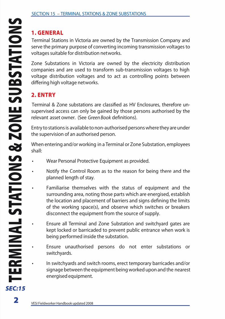
4. TERMINAL AND ZONE SUBSTATION SINGLE LINE
DIAGRAMS
Terminal stations and Zone substations are drawn schematically. Schematic
drawings represent the elements o a system using symbols and generally
straight lines. They usually omit all details that are not relevant to the
inormation being portrayed.For Terminal and Zone substations, these schematic drawings are known
as single line diagrams. An example is shown in Figure 1 on the ollowing
page
8/4/2019 Section 15 - Terminal Stations and Zone Substations
http://slidepdf.com/reader/full/section-15-terminal-stations-and-zone-substations 4/18
4 VESI Fieldworker Handbook updated 2008
SECTION 15 – TERMINAL STATIONS & ZONE SUBSTATIONS
T
E R M I N A L
S T A T I O N
S & Z O N E
S U B S T A T
I O N S
SEC:15
Figure 1
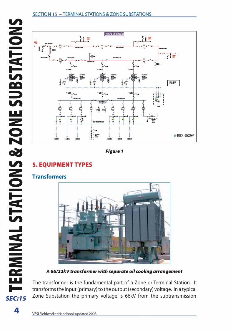
5. EQUIPMENT TYPES
Transormers
A 66/22kV transformer with separate oil cooling arrangement
The transormer is the undamental part o a Zone or Terminal Station. It
transorms the input (primary) to the output (secondary) voltage. In a typicalZone Substation the primary voltage is 66kV rom the subtransmission
8/4/2019 Section 15 - Terminal Stations and Zone Substations
http://slidepdf.com/reader/full/section-15-terminal-stations-and-zone-substations 5/18
5VESI Fieldworker Handbook updated 2008
SECTION 15 – TERMINAL STATIONS & ZONE SUBSTATIONS T E R M
I N A L S T A T I O N S &
Z O N E S U
B S T A T I O N
S SEC:15
network and the secondary voltage is 22kV or supply to the distribution
network. A typical Zone Substation transormer in an urban station is rated
at 20/33MVA. The 20 MVA rating applies with natural cooling and the 33MVA
rating is achieved using orced cooling which can include oil pumps and
ans. A transormer o this type will contain approximately 18,000 litres
o transormer oil to acilitate cooling and insulation o the transormer
windings and weigh approximately 45 tonne. Transormers are located
within bunded areas to prevent environmental damage should an oil spill
occur.
Most transormers are also ftted with on-load tap changers to maintain
the secondary voltage at a constant level with varying loads on the
transormer.
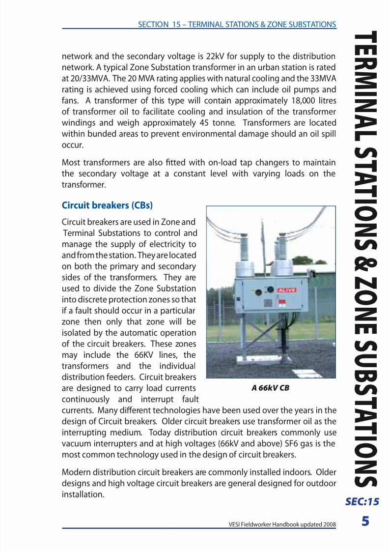
Circuit breakers (CBs)
Circuit breakers are used in Zone and
Terminal Substations to control and
manage the supply o electricity to
and rom the station. They are located
on both the primary and secondary
sides o the transormers. They are
used to divide the Zone Substationinto discrete protection zones so that
i a ault should occur in a particular
zone then only that zone will be
isolated by the automatic operation
o the circuit breakers. These zones
may include the 66KV lines, the
transormers and the individual
distribution eeders. Circuit breakers
are designed to carry load currentscontinuously and interrupt ault
currents. Many dierent technologies have been used over the years in the
design o Circuit breakers. Older circuit breakers use transormer oil as the
interrupting medium. Today distribution circuit breakers commonly use
vacuum interrupters and at high voltages (66kV and above) SF6 gas is the
most common technology used in the design o circuit breakers.
Modern distribution circuit breakers are commonly installed indoors. Older
designs and high voltage circuit breakers are general designed or outdoorinstallation.
A 66kV CB
8/4/2019 Section 15 - Terminal Stations and Zone Substations
http://slidepdf.com/reader/full/section-15-terminal-stations-and-zone-substations 6/18
6 VESI Fieldworker Handbook updated 2008
SECTION 15 – TERMINAL STATIONS & ZONE SUBSTATIONS
T
E R M I N A L
S T A T I O N
S & Z O N E
S U B S T A T
I O N S
SEC:15
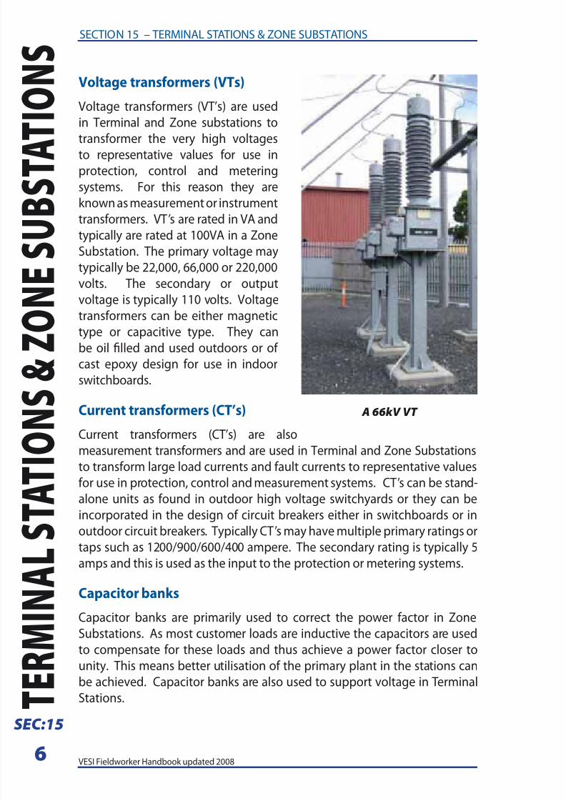
Voltage transormers (VTs)
Voltage transormers (VT’s) are used
in Terminal and Zone substations to
transormer the very high voltagesto representative values or use in
protection, control and metering
systems. For this reason they are
known as measurement or instrument
transormers. VT’s are rated in VA and
typically are rated at 100VA in a Zone
Substation. The primary voltage may
typically be 22,000, 66,000 or 220,000
volts. The secondary or outputvoltage is typically 110 volts. Voltage
transormers can be either magnetic
type or capacitive type. They can
be oil flled and used outdoors or o
cast epoxy design or use in indoor
switchboards.
Current transormers (CT’s)
Current transormers (CT’s) are also
measurement transormers and are used in Terminal and Zone Substations
to transorm large load currents and ault currents to representative values
or use in protection, control and measurement systems. CT’s can be stand-
alone units as ound in outdoor high voltage switchyards or they can be
incorporated in the design o circuit breakers either in switchboards or in
outdoor circuit breakers. Typically CT’s may have multiple primary ratings or
taps such as 1200/900/600/400 ampere. The secondary rating is typically 5
amps and this is used as the input to the protection or metering systems.
Capacitor banks
Capacitor banks are primarily used to correct the power actor in Zone
Substations. As most customer loads are inductive the capacitors are used
to compensate or these loads and thus achieve a power actor closer to
unity. This means better utilisation o the primary plant in the stations can
be achieved. Capacitor banks are also used to support voltage in Terminal
Stations.
A 66kV VT

8/4/2019 Section 15 - Terminal Stations and Zone Substations
http://slidepdf.com/reader/full/section-15-terminal-stations-and-zone-substations 7/18
7VESI Fieldworker Handbook updated 2008
SECTION 15 – TERMINAL STATIONS & ZONE SUBSTATIONS T E R M
I N A L S T A T I O N S &
Z O N E S U
B S T A T I O N
S SEC:15
Capacitor banks are oten switched
on and o according to the time
o day or the MVAR load on the
station. Modern capacitor banks
are comprised o small individual
capacitor cans o approximately 300
kVAR each. These are connected
together in series and parallel
combinations to make capacitor
banks o up to 12 MVAR rating in
Zone Substations.
Substation capacitor banks, cases and support structures shall be considered
energised at ull potential until Isolated. A minimum delay o fve minutesmust be observed beore earthing. Beore individual units are handled they
shall be short-circuited between all terminals and the case. I the cases o
capacitors are in earthed substation racks, the racks shall be bonded to
earth. Any line to which capacitors are connected shall be short-circuited
beore it is considered sae or access.
Station services transormers
The Station Service Transormerprovides the 415/240V supplies
at a Terminal Station or a Zone
Substation used to power all
auxiliary equipment on the station.
This includes the light and power
to all buildings, the supply to the
tap changers on the transormers,
the cooling ans and pumps on
the transormers and the batterychargers that maintain the DC
supplies or the station. In Zone
Substations the Station Services
Transormer is typically rated at 50
or 100 kVA. They may be pole or
platorm mounted transormers or
kiosk types. In Zone Substations they
are oten supplied at the distribution
voltage rom one o the eeder circuit
breakers or directly rom a distribution bus.
A 22kV Capacitor Bank
A 22kV Station Service Transformer
8/4/2019 Section 15 - Terminal Stations and Zone Substations
http://slidepdf.com/reader/full/section-15-terminal-stations-and-zone-substations 8/18
8 VESI Fieldworker Handbook updated 2008
SECTION 15 – TERMINAL STATIONS & ZONE SUBSTATIONS
T
E R M I N A L
S T A T I O N
S & Z O N E
S U B S T A T
I O N S
SEC:15
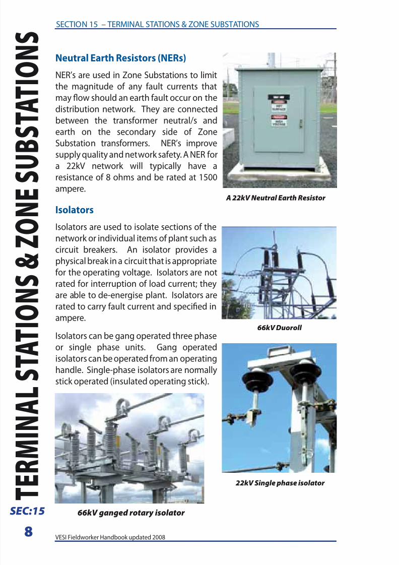
Neutral Earth Resistors (NERs)
NER’s are used in Zone Substations to limit
the magnitude o any ault currents that
may ow should an earth ault occur on thedistribution network. They are connected
between the transormer neutral/s and
earth on the secondary side o Zone
Substation transormers. NER’s improve
supply quality and network saety. A NER or
a 22kV network will typically have a
resistance o 8 ohms and be rated at 1500
ampere.
Isolators
Isolators are used to isolate sections o the
network or individual items o plant such as
circuit breakers. An isolator provides a
physical break in a circuit that is appropriate
or the operating voltage. Isolators are not
rated or interruption o load current; they
are able to de-energise plant. Isolators arerated to carry ault current and specifed in
ampere.
Isolators can be gang operated three phase
or single phase units. Gang operated
isolators can be operated rom an operating
handle. Single-phase isolators are normally
stick operated (insulated operating stick).
A 22kV Neutral Earth Resistor
66kV Duoroll
22kV Single phase isolator
66kV ganged rotary isolator
8/4/2019 Section 15 - Terminal Stations and Zone Substations
http://slidepdf.com/reader/full/section-15-terminal-stations-and-zone-substations 9/18
9VESI Fieldworker Handbook updated 2008
SECTION 15 – TERMINAL STATIONS & ZONE SUBSTATIONS T E R M
I N A L S T A T I O N S &
Z O N E S U
B S T A T I O N
S SEC:15
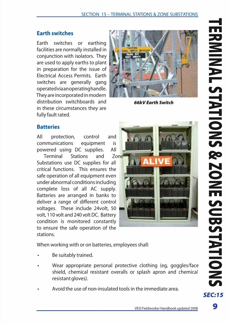
Earth switches
Earth switches or earthing
acilities are normally installed in
conjunction with isolators. Theyare used to apply earths to plant
in preparation or the issue o
Electrical Access Permits. Earth
switches are generally gang
operated via an operating handle.
They are incorporated in modern
distribution switchboards and
in these circumstances they are
ully ault rated.
Batteries
All protection, control and
communications equipment is
powered using DC supplies. All
Terminal Stations and Zone
Substations use DC supplies or all
critical unctions. This ensures thesae operation o all equipment even
under abnormal conditions including
complete loss o all AC supply.
Batteries are arranged in banks to
deliver a range o dierent control
voltages. These include 24volt, 50
volt, 110 volt and 240 volt DC. Battery
condition is monitored constantly
to ensure the sae operation o thestations.
When working with or on batteries, employees shall:
• Be suitably trained.
• Wear appropriate personal protective clothing (eg, goggles/ace
shield, chemical resistant overalls or splash apron and chemical
resistant gloves).
• Avoid the use o non-insulated tools in the immediate area.
66kV Earth Switch
8/4/2019 Section 15 - Terminal Stations and Zone Substations
http://slidepdf.com/reader/full/section-15-terminal-stations-and-zone-substations 10/18
10 VESI Fieldworker Handbook updated 2008
SECTION 15 – TERMINAL STATIONS & ZONE SUBSTATIONS
T
E R M I N A L
S T A T I O N
S & Z O N E
S U B S T A T
I O N S
SEC:15
• Remove contaminated clothing and wash the skin with water
immediately, should electrolyte be spilled.
• NOT smoke or use naked ames.
• Use ventilation where provided.
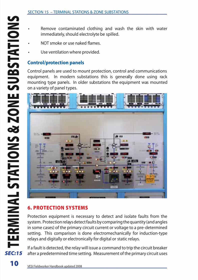
Control/protection panels
Control panels are used to mount protection, control and communications
equipment. In modern substations this is generally done using rack
mounting type panels. In older substations the equipment was mounted
on a variety o panel types.
6. PROTECTION SYSTEMS
Protection equipment is necessary to detect and isolate aults rom the
system. Protection relays detect aults by comparing the quantity (and angles
in some cases) o the primary circuit current or voltage to a pre-determined
setting. This comparison is done electromechanically or induction-type
relays and digitally or electronically or digital or static relays.
I a ault is detected, the relay will issue a command to trip the circuit breaker
ater a predetermined time setting. Measurement o the primary circuit uses

8/4/2019 Section 15 - Terminal Stations and Zone Substations
http://slidepdf.com/reader/full/section-15-terminal-stations-and-zone-substations 11/18
11VESI Fieldworker Handbook updated 2008
SECTION 15 – TERMINAL STATIONS & ZONE SUBSTATIONS T E R M
I N A L S T A T I O N S &
Z O N E S U
B S T A T I O N
S SEC:15
instrument transormers (ie CT’s and VT’s) to allow indirect, saer and more
manageable connections to high voltage and/or high current equipment.
The main protection unctions or distribution and subtransmission circuits
are:
Overcurrent
The relay starts to operate (pick up) when current magnitude exceeds the
preset current setting. Overcurrent can be detected in phase conductors,
neutral conductors and/or the earth return path:
• Phase-overcurrent or “overcurrent” protection is where current in a
phase conductor is measured.
• Ground-overcurrent or “earth ault” protection is used to detect earth
aults whereby:
(a) the current in a specifc neutral or earth conductor is measured
and/or
(b) the residual current o the phase conductors o a 3 phase
system is measured. This is achieved by measuring the
“summed” current o the parallel connection o all phase CT’s,
or is calculated within the relay itsel, (applicable only to digitalrelays).
The residual current in a typical distribution HV network is zero during normal
conditions, even with extreme load unbalance. This is due to distribution
transormer primary winding and earthing confguration. Sensitive settings
can thereore be applied to earth ault relay, typically, a setting o 10>20%
o the nominal CT secondary current is used. It is possible or a residually
connected relay to operate when a high-resistance joints is present in one
phase o a multiple parallel circuit
Overcurrent relays invariable contain in-built timers to enable time-graded
coordination with other related relays. An inverse-time characteristic
provides a time delay that is inversely proportional to the current detected,
(ie the higher the current, the shorter the operating time).
Ground-overcurrent (earth ault) relays oten use a defnite-time characteristic
only, as the earth ault current magnitude does not vary so greatly between
two relaying points on a given network.
8/4/2019 Section 15 - Terminal Stations and Zone Substations
http://slidepdf.com/reader/full/section-15-terminal-stations-and-zone-substations 12/18
12 VESI Fieldworker Handbook updated 2008
SECTION 15 – TERMINAL STATIONS & ZONE SUBSTATIONS
T
E R M I N A L
S T A T I O N
S & Z O N E
S U B S T A T
I O N S
SEC:15
Directional overcurrent
Same as previous, with the addition that the direction o a ault can be
known by comparison o the primary circuit voltage and current. Directional
overcurrent is widely used in protection o ring or parallel eeders, whereault current can ow in either direction depending on the location o
the ault and supply source. Directional relays that look back directly into
a source can be set sensitively, as current owing in this direction will be
abnormal, and thus considered a ault.
Dierential protection
Compares the current entering the protected circuit (or zone) to the current
leaving the zone. A zone is bounded by measuring CT’s at the terminals o
the protected circuit. Where the terminals are some appreciable distance
apart, then a communications channel or pilot wire is required between
ends or dierential comparison, logic and inter-tripping acilities. There
are many various patented techniques available to perorm dierential
comparison and intertripping.
As dierential protection only operates or aults within a zone o protection,
there is no requirement to consider the operation times o protection outside
the zone; instantaneous operation is thereore oten applied to dierential
protection.
Distance protection
Distance relaying principles are based in impedance measurement and
so require the values o primary circuit voltage and current or any instant
time. The impedance o any given circuit is a fxed quality; i the impedance
measured by the relay has decreased to some value below a predetermined
setting, then a ault is assumed on the circuit and tripping can be initiated.
NOTE – On overhead line HV systems, many aults, particularly earth aults
may be transient ones, hence earth ault and overcurrent protection systems
may be associated with auto reclose relays. These relays automatically re-
close the circuit breakers ater a short pre-determined time and these usually
lock out ater a set number o unsuccessul attempts.
For HV Live Line work, auto-reclose shall be suppressed, or Live Line
Sequence (LLS) enabled. LLS gives instantaneous trip and sensitive earth
ault protection.
8/4/2019 Section 15 - Terminal Stations and Zone Substations
http://slidepdf.com/reader/full/section-15-terminal-stations-and-zone-substations 13/18
13VESI Fieldworker Handbook updated 2008
SECTION 15 – TERMINAL STATIONS & ZONE SUBSTATIONS T E R M
I N A L S T A T I O N S &
Z O N E S U
B S T A T I O N
S SEC:15
7. COMMUNICATION SYSTEMS
Remote control and indications o substations and feld equipment are vitalin ensuring sae, e cient and eective operation o an electrical distribution
network. This was the primary objective or the development o SCADAsystems, (Supervisory Control And Data Acquisition). As the name implies,the SCADA systems main unctions are to provide remote control o remotedevices and to return the status, alarm and system operating data romremote devices. Remote control is generally required rom one or morestrategically located control centres. The main control point is oten knownas the Network Control Centre, (NCC).
The SCADA master station which generally resides at the NCC,communicates to Remote Terminal Units (RTU’s) located at substations and
on feld equipment such as pole mount Auto-Reclosers. The SCADA masterinterrogates the RTU’s over a communications network. The medium or thecommunications networks can take many dierent orms; the most widelyused are radio, pilot or supervisory wire and fbre-optic.
The substation RTU is generally equipped with digital and analogue Input/Output (I/O) to interace with substation devices. The main unction o digital I/O is to provide or the display o the operating status o feldequipment (eg indicating a breaker in either the open or closed position)
and or operational control o feld equipment (eg operating to open orclose a breaker). Analogue I/O is generally used to provide or the display o real-time values o the electrical quantities seen by a particular device, (egthe load current through a breaker, or the voltage on a busbar).
Control centre communications can also be achieved with IntelligentElectronic Devices (IED’s) such as digital relays via serial communicationslinked to the RTU or to the SCADA master itsel. The main beneft o this isthat event data, indication and control points available within the IED can be
accessed remotely via SCADA.
8. EARTH GRIDS
The earth grids installed in Terminal Stations and Zone Substations serve the
ollowing purposes:
As a Voltage Reference Point for the Network Supplied
The secondary windings o the transormers in Terminal Stations and
Zone Substations are connected to the earth grid so that the voltages on
the network are maintained at the specifed values with respect to earth. That is the distribution network voltage (e.g. 22kV) is held constant by the
connection to the earth grid.

8/4/2019 Section 15 - Terminal Stations and Zone Substations
http://slidepdf.com/reader/full/section-15-terminal-stations-and-zone-substations 14/18
14 VESI Fieldworker Handbook updated 2008
SECTION 15 – TERMINAL STATIONS & ZONE SUBSTATIONS
T
E R M I N A L
S T A T I O N
S & Z O N E
S U B S T A T
I O N S
SEC:15
For the Management of Fault Current
The earth grid in Terminal Stations and Zone Substations is designed to
acilitate the return o earth ault current rom aults on the network it supplies
to the source o the ault current, the Zone Substation transormer. This thenensures that enough ault current ows to operate protective devices such as
uses and circuit breakers. Any earth ault on a distribution eeder, such as a
possum strike on a concrete high voltage pole, results in ault current owing
into the pole and the ground and then returning to the zone substation
transormer via the earth grid at the Zone Substation. Consequently the
earth grid has to be designed and built to carry the large currents that may
be associated with network earth aults. Earth conductor sizes and the
integrity o all connections are critical to the sae operation o the earth grid.
All plant within a substation such as transormers, circuit breakers, surgediverters and bus support structures etc. are all bonded to the earth grid
in the station so that in the event o a ailure the ault current can be saely
managed.
Saety
The earth grid in Terminal Stations and Zone Substations also ensures the
saety o all people working in the substation by limiting the step and touch
voltages that can occur under ault conditions. When ault current owsinto and earth grid dangerous voltage rises can occur on the earth grid. The
design o the earth grid is intended to manage these voltage rises, should
they occur, so that people within and outside the substation are not exposed
to dangerous voltages.
Work on earth grids
Special precautions must be taken when working on in service earth grids to
prevent exposure to hazardous voltages should a network earth ault occur
at the time the works are being undertaken. These precautions may include
the use o bonders and insulating gloves.
Station earths
Earthing receptacles and acilities are provided in Zone Substation to permit
the eecting bonding to earth o plant and lines using portable earthing
equipment. This then permits the sae issue o Electrical Access Permits
or the maintenance o this substation equipment by ensuring that the
equipment remains at earth potential.

8/4/2019 Section 15 - Terminal Stations and Zone Substations
http://slidepdf.com/reader/full/section-15-terminal-stations-and-zone-substations 15/18
15VESI Fieldworker Handbook updated 2008
SECTION 15 – TERMINAL STATIONS & ZONE SUBSTATIONS T E R M
I N A L S T A T I O N S &
Z O N E S U
B S T A T I O N
S SEC:15
9. MOBILE PLANT & EXCAVATING WITHIN STATIONS
A person shall not perorm work in any station or allow mobile plant to enter
any station without frst obtaining the permission o the person in charge o
the station and, accepting all the conditions imposed by that person.
An Access Authority shall be issued in a Terminal and Zone Substation
where:
• Mobile plant or other large vehicles will be used.
• The work involves excavation or the use o explosives.
• Where Ordinary Persons are involved.
Mobile plant when in the travelling mode within Zone substations or Terminal stations shall have a trailing earth lowered. When in a stationary
working mode the mobile plant shall be connected to the station earth
grid.
The work party shall ensure that work does not require the earthed portions
o the mobile plant to move outside the perimeter o the station earth
grid;
Beore starting an excavation in any energised station, the crew leader shallobtain all available inormation on existing subsurace structures such as
power and control cables, pipes, ground wires, etc. Work in the vicinity o
all such assets shall be done with great care. The crew leader in conjunction
with the operating authority shall designate the limits o the excavation
and the employees shall keep within these limits.
Any accidental opening in the earthing system shall be repaired using high
voltage rubber gloves or by bridging out the opening. Caution must be
observed, as this is possibly an energised open circuit. I a section o the
substation ence is extended or removed, earthing and bonding continuity
shall be maintained at all times.
8/4/2019 Section 15 - Terminal Stations and Zone Substations
http://slidepdf.com/reader/full/section-15-terminal-stations-and-zone-substations 16/18
16 VESI Fieldworker Handbook updated 2008
SECTION 15 – TERMINAL STATIONS & ZONE SUBSTATIONS
T
E R M I N A L
S T A T I O N
S & Z O N E
S U B S T A T
I O N S
SEC:15
10. ELECTRICAL TESTING AND TEST FACILITIES
NOTE: This section applies to fxed and temporary test sites using high
voltage and/or high power, but does not include routine work such as
phasing or checking or voltage on a de-energised line.
When carrying out electrical testing involving secondary Isolations in a Zone
Substation, employees shall:
• Be trained and authorised.
• Protect the test areas using appropriate barriers with danger signs
attached.
• Ensure test trailers and vehicles are earthed, and employees are
protected against step and touch potential with bonding, insulation or
isolation techniques.
11. GAS INSULATED EQUIPMENT
Employees shall wear company approved protective clothing to avoid
skin contact with powder residue that may be ound inside the SF6 gas
containment system.
Manuacturer’s cautions shall be ollowed when perorming maintenance
on breakers or buses. This includes product bulletins, saety bulletins, and
manuacturer’s warnings.
When working on SF6 equipment, special precautions should be taken not
to breathe the SF6 gas or its by-product.
Employees shall use a regulator, gauge, and hose or proper PSI rating when
flling or adding SF6 gas.
12. ZONE SUBSTATION SWITCHING
Beore switching is perormed in a substation where work is in progress,the employee perorming the switching shall notiy all personnel workingwithin the substation.
All other personnel shall be clear o the work area during the time anycircuit breaker is being racked in or out. The circuit breaker shall be in theopen position and the control circuit rendered inoperative by activating theoperator saety switch, i the design so permits.
The application o earthing devices to isolated contacts within the spouts o metal-clad switchgear shall be supervised by an Authorised Person.
Any employee who has carried out switching or maintenance in a Zone
Substation shall record the details o their work in the Substation logbook.
8/4/2019 Section 15 - Terminal Stations and Zone Substations
http://slidepdf.com/reader/full/section-15-terminal-stations-and-zone-substations 17/18
17VESI Fieldworker Handbook updated 2008
SECTION 15 – TERMINAL STATIONS & ZONE SUBSTATIONS T E R M
I N A L S T A T I O N S &
Z O N E S U
B S T A T I O N
S SEC:15
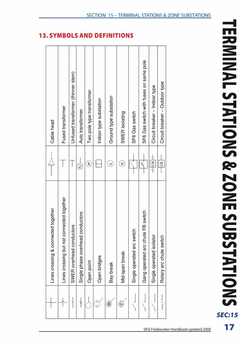
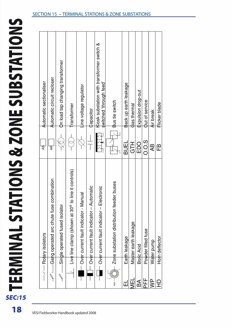
13. SYMBOLS AND DEFINITIONS
L i n e s c r o s s i n g & c o n
n e c t e d t o g e t h e r
C a b l e h e a d
L i n e s c r o s s i n g b u t n o t c o n n e c t e d t o g e t h e r
F u s e d t r a n s f o r m e r
S W E R o v e r h e a d c o n d u c t o r s
U n f u s e d t r a
n s f o r m e r ( t h i n n e r s t e m )
S i n g l e p h a s e o v e r h e
a d c o n d u c t o r s
A T
A u t o t r a n s f o r m e r
O p e n p o i n t
2 P
T w o p o l e t y
p e t r a n s f o r m e r
O p e n b r i d g e s
I n d o o r t y p e
s u b s t a t i o n
B
B a y b r e a k
G
G r o u n d t y p e s u b s t a t i o n
MS
M i d - s p a n b r e a k
I S
S W E R I s o l a t i n g
S i n g l e o p e r a t e d a r c
s w i t c h
S F 6 G a s s w
i t c h
G a n g o p e r a t e d a r c c
h u t e F B s w i t c h
S F 6 G a s s w
i t c h w i t h f u s e s o n s a m e p o l e
S i n g l e o p e r a t e d i s o l a t o r
C B
C i r c u i t b r e a
k e r – I n d o o r t y p e
R o t a r y a r c c h u t e s w i t c h
C B
C i r c u i t b r e a
k e r – O u t d o o r t y p e
8/4/2019 Section 15 - Terminal Stations and Zone Substations
http://slidepdf.com/reader/full/section-15-terminal-stations-and-zone-substations 18/18
18
SECTION 15 – TERMINAL STATIONS & ZONE SUBSTATIONS
T
E R M I N A L
S T A T I O N
S & Z O N E
S U B S T A T
I O N S
SEC:15
R o t a r y i s o l a t o r s
A S
A u t o m a t i c s e c t i o n a l i s e r
G a n g o p e r a t e d a r c c h u t e f u s e c o m b i n a t i o n
A R
A u t o m a t i c c i r c u i t r e c l o s e r
S i n g l e o p e r a t e d f u s e d i s o l a t o r
O n l o a
d t a p c h a n g i n g t r a n s f o r m e r
L i v e l i n e c l a m p ( s
h o w n a t 3 0 °
t o l i n e i t c o n t r o l s )
T r a n s f o r m e r
O v e r c u r r e n t f a u l t i n d i c a t o r - M a n u a l
L i n e v o
l t a g e r e g u l a t o r
O v e r c u r r e n t f a u l t i n d i c a t o r – A u t o m a t i c
C a p a c i t o r
O v e r c u r r e n t f a u l t i n d i c a t o r – E l e c t r o n i c
K i o s k s u b s t a t i o n w i t h t r a n s f o r m e r s w i t c h &
s w i t c h e d ‘ t h r o u g h f e e d ’
Z o n e s u b s t a t i o n d i s t r i b u t i o n f e e d e r b u s e s
B u s t i e
s w i t c h
E L
E a r t h l e a k a g e
B U E L
B a c k u
p e a r t h l e a k a g e
M
E L
M a s t e r e a r t h l e a k
a g e
G T H
G a s t h
e r m a l
B A
B o r i c A c i d
E D O
E x p u l s
i o n d r o p - o u t
P F F
P o w d e r f i l l e d f u s e
O . O . S
O u t o f
s e r v i c e
W P
W a t e r p u m p
A B
A i r b r e
a k
H D
H o r n d e f l e c t o r
F B
F l i c k e r
b l a d e
R B D