zxmp m820 product description - liberty port · 3.1.12 alarm input /output function ... zxmp m820...
TRANSCRIPT

ZXMP M820 Product Description

ZXMP M820 Product Description
ZTE Confidential Proprietary 1
ZXMP M820
Product Description Version Date Author Reviewer Notes
V2.4 2009-07-02 Zhao Shuai Wei Xiaoqiang Not open to the Third Party
V2.5 2010-04-14 Chi Yongjie Wei Xiaoqiang Not open to the Third Party
V2.51 2010-02-28 Zhao Shuai Wei Xiaoqiang Not open to the Third Party
V2,52 2012-06-30 Zhao Shuai Tu Yong Not open to the Third Party
V2,60 2013-1-30 Zhao Shuai Xu Kun Not open to the Third Party
© 2011 ZTE Corporation. All rights reserved.
ZTE CONFIDENTIAL: This document contains proprietary information of ZTE and is not to be disclosed or used
without the prior written permission of ZTE.
Due to update and improvement of ZTE products and technologies, information in this document is subjected to
change without notice.
ZXMP M820 Product Description
2 ZTE Confidential Proprietary
TABLE OF CONTENTS
1 Overview .......................................................................................................... 13
2 Highlight Features ........................................................................................... 15
2.1 Large Capacity and Easy Upgrade .................................................................... 15
2.2 Single 100Gbit/s system .................................................................................... 15
2.3 Single 40Gbit/s system ...................................................................................... 15
2.4 Super-long-haul Transmission ........................................................................... 16
2.5 Multi-service Access Mode ................................................................................ 17
2.6 Flexible networking modes ................................................................................. 17
2.7 Wavelength Add/Drop Functions ........................................................................ 17
2.8 Reliable Protection Functions ............................................................................ 18
2.9 Performance Monitoring Technology.................................................................. 18
2.10 Power Management Technology ........................................................................ 18
2.11 Powerful NM ...................................................................................................... 18
2.12 WASON ............................................................................................................. 19
3 Functionality .................................................................................................... 20
3.1 Functions ........................................................................................................... 20
3.1.1 Large Transmission Capacity ............................................................................. 20
3.1.2 Ultra-long-haul Distance Optical Source ............................................................ 20
3.1.3 Optical Amplifier ................................................................................................. 21
3.1.4 Power Management ........................................................................................... 22
3.1.5 Performance Detection Function ........................................................................ 25
3.1.6 OTN Description ................................................................................................ 26
3.1.7 Dispersion Management .................................................................................... 26
3.1.8 Service Functions .............................................................................................. 27
3.1.9 Wavelength Add/Drop Function ......................................................................... 28
3.1.10 Communication and Monitoring Functions ......................................................... 29
3.1.11 Time/Clock Synchronization Service .................................................................. 32
3.1.12 Alarm Input /Output Function ............................................................................. 33
3.1.13 System Level Protection .................................................................................... 33
3.1.14 Network level Protection .................................................................................... 34
3.1.15 Network management channel backup .............................................................. 37
3.1.16 L0/L1/L2 integrated transport technologies ........................................................ 39
3.1.17 ROADM Function ............................................................................................... 39
3.1.18 Electrical Cross-Connect Function ..................................................................... 41
3.1.19 Wavelength Tuning Function ............................................................................. 43
3.1.20 IWF Function ..................................................................................................... 45
3.2 Networking ......................................................................................................... 47

ZXMP M820 Product Description
ZTE Confidential Proprietary 3
3.2.1 System Applications ........................................................................................... 47
3.2.2 Networking Modes ............................................................................................. 53
3.3 Transmission Codes Supported ......................................................................... 56
4 System Architecture ........................................................................................ 61
4.1 Description of System Functional Platform ......................................................... 61
4.1.1 Optical transfer platform ..................................................................................... 61
4.1.2 Service convergence platform ............................................................................ 62
4.1.3 OM/OD platform ................................................................................................. 62
4.1.4 Add/drop platform .............................................................................................. 63
4.1.5 Optical amplifying platform ................................................................................. 63
4.1.6 Monitoring platform ............................................................................................ 63
4.2 Hardware Architecture ....................................................................................... 63
4.2.1 Sub-rack ............................................................................................................ 63
4.2.2 Board Description .............................................................................................. 66
4.3 The NM Software System Structure ................................................................... 78
4.3.1 Hierarchical structure ......................................................................................... 79
4.3.2 Interface description ........................................................................................... 81
4.4 System Configuration ......................................................................................... 82
4.4.1 Optical Terminal Multiplexer (OTM) ................................................................... 82
4.4.2 Optical Add/Drop Multiplexer (OADM) ................................................................ 82
4.4.3 Optical Line Amplifier (OLA) ............................................................................... 85
5 Technical Specifications ................................................................................. 87
5.1 Working Wavelength Requirements ................................................................... 87
5.1.1 Wavelength Allocation in 8/16/32/40-Channel Systems ..................................... 87
5.1.2 Wavelength Allocation in 48/96 Wavelength System .......................................... 88
5.1.3 Wavelength Allocation in 80/160 Wavelength System ........................................ 90
5.1.4 Wavelength Allocation in 176-Channel Systems ................................................ 94
5.1.5 Wavelength Allocation in 192-Channel Systems ................................................ 94
5.2 System Component Indices ............................................................................... 98
5.3 OMU/ODU Unit Specifications ........................................................................... 99
5.3.1 Specifications of OMU Board ............................................................................. 99
5.3.2 Specifications of ODU Board............................................................................ 101
5.3.3 Specifications of ODUB Board ......................................................................... 102
5.3.4 Specifications of VMUX Board ......................................................................... 103
5.3.5 Specifications of VMUXB Board ....................................................................... 104
5.3.6 Specifications of OCI Board ............................................................................. 104
5.3.7 Specifications of OBM Board ........................................................................... 105
5.4 WSUA/WSUD & WBU Unit Specifications........................................................ 106
5.5 OADM Unit Specifications ................................................................................ 110
5.6 OA Unit Specifications ..................................................................................... 110
ZXMP M820 Product Description
4 ZTE Confidential Proprietary
5.6.1 Specifications of EOBA (Enhanced Optical Booster Amplifier) Board............... 111
5.6.2 Specifications of EOLA (Enhanced Optical Line Amplifier) Board .................... 117
5.6.3 Specifications of EOPA (Optical preamplifier) Board ........................................ 118
5.6.4 Specifications of EONA (Enhanced Optical Node Amplifier) Board .................. 124
5.6.5 Specifications of SEOBA Board ....................................................................... 127
5.6.6 Specifications of SEOPA Board ....................................................................... 129
5.6.7 Specifications of SEOLA Board ........................................................................ 131
5.6.8 Specifications of EDFA+RAMAN Board ........................................................... 133
5.6.9 Specifications of RPOA Board ......................................................................... 135
5.6.10 Specifications of LAC Board ............................................................................ 135
5.7 OTU Unit Specifications ................................................................................... 136
5.7.1 Specifications of 2.5Gbit/s Board ..................................................................... 136
5.7.2 Specifications of 10Gbit/s Board ...................................................................... 138
5.7.3 Specifications of 40Gbit/s Board ...................................................................... 141
5.7.4 Specifications of 100Gbit/s Board .................................................................... 143
5.8 Service Convergence Technical Specifications ................................................ 145
5.8.1 Specifications of SRM41 Board ........................................................................ 145
5.8.2 Specifications of SRM42 Board ........................................................................ 147
5.8.3 Specifications of MQT3 Board.......................................................................... 149
5.8.4 Specifications of MX2 Board ............................................................................ 151
5.8.5 Specifications of FCA Board ............................................................................ 153
5.8.6 Specifications of MOM2 Board ......................................................................... 154
5.8.7 Specifications of GEM8 Board ......................................................................... 155
5.8.8 Specifications of SDSA Board .......................................................................... 157
5.8.9 Specifications of DSA Board ............................................................................ 158
5.8.10 Specifications of DSAF Board .......................................................................... 160
5.8.11 Specifications of GEM2/GEMF Board .............................................................. 161
5.8.12 Specifications of ASMA Board ......................................................................... 162
5.8.13 Specifications of TD2C Board .......................................................................... 164
5.8.14 Specifications of MQA1 Board ......................................................................... 165
5.8.15 Specifications of MQA2 Board ......................................................................... 167
5.8.16 Specifications of MJA Board ............................................................................ 168
5.9 Electrical Cross-connection Subsystem Specifications .................................... 169
5.9.1 Specifications of CH1 Board ............................................................................ 169
5.9.2 Specifications of CO2 Board ............................................................................ 170
5.9.3 Specifications of CQ2 Board ............................................................................ 171
5.9.4 Specifications of CS3 Board ............................................................................ 172
5.9.5 Specifications of CD3 Board ............................................................................ 172
5.9.6 Specifications of LO2 Board ............................................................................. 175
5.9.7 Specifications of LQ2 Board ............................................................................. 176
5.9.8 Specifications of LD2B Board........................................................................... 178
5.9.9 Specifications of LS3 Board ............................................................................. 178

ZXMP M820 Product Description
ZTE Confidential Proprietary 5
5.10 Tributary overhead processing of convergence board ...................................... 180
5.11 OS Channel (SOSC) Unit Specifications .......................................................... 181
5.12 Supervision Unit Specifications ........................................................................ 181
5.13 Dispersion Compensation Unit Specifications .................................................. 182
5.14 Dispersion compensation unit (DCU) Performance Indices .............................. 182
5.15 Physical Performance ...................................................................................... 183
5.15.1 Structure Indices .............................................................................................. 183
5.15.2 Bearing Requirements of the Equipment Room ............................................... 188
5.15.3 Power Supply Indices ...................................................................................... 188
5.16 Environment Conditions ................................................................................... 193
5.16.1 Grounding Requirements ................................................................................. 193
5.16.2 Temperature and Humidity Requirements ........................................................ 194
5.16.3 Requirements for Cleanness ............................................................................ 194
5.16.4 Dustproof and Corrosion-Proof Requirements ................................................. 195
5.16.5 Environment for Storage .................................................................................. 195
5.16.6 Environment for Transportation ........................................................................ 196
5.16.7 Electronic Static Discharge (ESD) .................................................................... 197
5.16.8 Safety requirements ......................................................................................... 199
5.17 Introduction to Interfaces .................................................................................. 202
5.17.1 Interface on SEIA board ................................................................................... 202
5.17.2 Interface on SPWA board ................................................................................ 206
6 Abbreviation .................................................................................................. 209
7 Followed Standards and Recommendations ............................................... 214

ZXMP M820 Product Description
6 ZTE Confidential Proprietary
FIGURES
Figure 1-1 Rack Diagram of Unitrans® ZXMP M820 ...........................................................13
Figure 1-2 ZTE’s New-Generation Digital Transmission Product Family ............................14
Figure 3-1 Principles of RA ................................................................................................22
Figure 3-2 Power management sub-system .......................................................................24
Figure 3-3 Dispersion management ...................................................................................27
Figure 3-4 Position of supervision subsystem ....................................................................32
Figure 3-5 The Block Diagram of Optical Path 1: N Protection Function ............................34
Figure 3-6 Optical Path Layer 1+1 Protection (Chain Networking) .....................................35
Figure 3-7 Ring Networking ...............................................................................................36
Figure 3-8 Functional Block Diagram for MS 1+1 Protection ..............................................36
Figure 3-9 Schematic diagram of 2-fiber bidirectional path shared protection ....................37
Figure 3-10 Network management through supervisory channel .......................................38
Figure 3-11 Network management through backup supervisory channel ...........................39
Figure 3-12 Electrical Cross-Connect System Structural Diagram .....................................42
Figure 3-13 Functional Blocks of IWF Function (External Wavelength Feedback) .............46
Figure 3-14 Whole Network Application with the ZXMP M820 (the System less than 48-Wavelength) ....................................................................................................................47
Figure 3-15 Whole Network Application with the ZXMP M820 (the System with 80/96-Wavelength) ...............................................................................................................49
Figure 3-16 Whole Network Application with the ZXMP M820 (160/176- Wavelength) .......50
Figure 3-17 Whole Network Application with the ZXMP M820 (the System with 192-Wavelength) ..................................................................................................................52
Figure 3-18 Point-to-Point Networking (Short-Haul) ...........................................................54
Figure 3-19 Point-to-Point Networking (Long-Haul) ............................................................54
Figure 3-20 Application of Chain Networking .....................................................................54
Figure 3-21 Application of Ring Networking .......................................................................55
Figure 3-22 Ring-with-Chain Networking ............................................................................55
Figure 3-23 Cross Connection Networking .........................................................................56
Figure 4-1 Functional Blocks of the ZXMP M820 ...............................................................61
ZXMP M820 Product Description
ZTE Confidential Proprietary 7
Figure 4-2 Layout of ZXMP M820 NX Sub-rack (21 inch) ..................................................64
Figure 4-3 Layout of ZXMP M820 NX Sub-rack (19 inch) ..................................................64
Figure 4-4 Slot Arrangement of CX Sub-rack .....................................................................65
Figure 4-5 Slot Arrangement of DX Sub-rack .....................................................................65
Figure 4-6 Hierarchical Structure of the Element Management Software ...........................79
Figure 4-7 Functional Blocks of the OTM ...........................................................................82
Figure 4-8 Functional Blocks of the FOADM ......................................................................83
Figure 4-9 Optical Connection of ROADM Equipment with WBU Boards ...........................84
Figure 4-10 Optical Connection of ROADM Equipment with WBM Boards .........................84
Figure 4-11 Optical Connection of ROADM Equipment with WSU Boards .........................85
Figure 4-12 Functional Blocks of the OLA ..........................................................................86
Figure 5-1 Schematic Diagram of the DWDM System ........................................................98
Figure 5-2 Common Interface Area of the OTU Sub-rack ................................................ 202
Figure 5-3 Interfaces on the SPWA board ........................................................................ 206

ZXMP M820 Product Description
8 ZTE Confidential Proprietary
TABLES
Table 3-1 Characteristics of dual/single pump source ........................................................22
Table 3-2 ZTE Networking Scheme and Application Environment .....................................40
Table 3-3 ZTE/ ROADM Solutions .....................................................................................41
Table 3-4 Boards Supporting Wavelength Tuning Function ...............................................44
Table 3-5 Transmission Codes Supported by 40 2.5Gbit/s System (G.652&G.655) .........56
Table 3-6 Transmission Codes Supported by 40 /48 10Gbit/s System (G.652&G.655) ....57
Table 3-7 Transmission Codes Supported by 80/96 10Gbit/s System (G.652&G.655) ....57
Table 3-8 Transmission Codes Supported by 192 10Gbit/s System (G.652&G.655) .......58
Table 3-9 Transmission Codes Supported by 40/48 40Gbit/s System (G.652&G.655) ....58
Table 3-10 Transmission Codes Supported by 80/96 40Gbit/s System (G.652&G.655) ..58
Table 3-11 Transmission Codes Supported by 80 100Gbit/s System (G.652 with DCM) .59
Table 3-12 Transmission Codes Supported by 80 100Gbit/s System (G.652 without DCM) .............................................................................................................................................59
Table 3-13 Transmission Codes Supported by 80 100Gbit/s System (G.655 with DCM) .59
Table 3-14 Transmission Codes Supported by 80 100Gbit/s System (G.655 without DCM) .............................................................................................................................................60
Table 4-1 Board Description ..............................................................................................66
Table 5-1 Wavelength Allocation (8/16/32/40-channel, C band) .........................................87
Table 5-2 Wavelength Allocation (48/96-channel, C band).................................................88
Table 5-3 Wavelength Allocation (80-channel, C band) .....................................................90
Table 5-4 Wavelength Allocation (80-channel, L band) ......................................................92
Table 5-5 Wavelength Allocation (192-channel, C band) ...................................................94
Table 5-6 Meaning of Components and Interfaces of the DWDM System ..........................98
Table 5-7 Technical specifications of OMU Board ..............................................................99
Table 5-8 Technical specifications of ODU Board ............................................................ 101
Table 5-9 Technical Specifications of the ODUB Board ................................................... 102
Table 5-10 Technical specifications of VMUX Board ........................................................ 103
Table 5-11 Technical specifications of VMUXB Board ..................................................... 104

ZXMP M820 Product Description
ZTE Confidential Proprietary 9
Table 5-12 Technical Specifications of the OCI Board (100GHz-50GHz) ......................... 104
Table 5-13 Technical Specifications of the OCI Board (50GHz-25GHz) ........................... 105
Table 5-14 Technical Specifications of the OBM Board ................................................... 105
Table 5-15 Technical specifications of WBU Board .......................................................... 106
Table 5-16 Technical specifications of WSUA/WSUD Board ............................................ 107
Table 5-17 Technical specifications of WBM Board ......................................................... 107
Table 5-18 Technical specifications of PDU-4-X Board .................................................... 108
Table 5-19 Technical specifications of PDU-5-X Board .................................................... 108
Table 5-20 Technical specifications of PDU-8-X board .................................................... 109
Table 5-21 Technical specifications of PDU-9-X Board .................................................... 109
Table 5-22 Technical specifications of PDU-16-X Board .................................................. 109
Table 5-23 Technical specifications of OADM Board ....................................................... 110
Table 5-24 Technical specifications of 40-channel EOBA Board (C/L-band) .................... 111
Table 5-25 Technical specifications of 80-channel EOBA Board (C/L-band) .................... 112
Table 5-26 Technical specifications of 48-channel EOBA Board (C-band) ....................... 114
Table 5-27 Technical specifications of 96-channel EOBA Board (C-band) ....................... 115
Table 5-28 echnical specifications of 40/80-channel EOLA Board (C/L-band) ................. 117
Table 5-29 Technical specifications of 40-channel EOPA Board (C/L-band) .................... 119
Table 5-30 Technical specifications of 40-channel EOPA Board (C/L-band) .................... 120
Table 5-31 Technical specifications of 48-channel EOPA Board (C-band) ....................... 122
Table 5-32 Technical specifications of 96-channel EOPA Board (C-band) ....................... 123
Table 5-33 Technical specifications of 40/80-channel EONA Board (C/L-band) ............... 124
Table 5-34 Technical specifications of 48/96-channel EONA Board (C/L-band) ............... 126
Table 5-35 Technical specifications of 40/80-channel SEOBA Board (C- Band) .............. 128
Table 5-36 Technical specifications of 40-channel SEOPA Board (C-band) .................... 129
Table 5-37 Technical specifications of 80-channel SEOPA Board (C-band) ..................... 130
Table 5-38 Technical specifications of 40/80-channel SEOLA Board (C-band) ................ 131
Table 5-39 Technical specifications of RAMAN_P amplifier ............................................. 133
Table 5-40 Technical specifications of EDFA+RAMAN Amplifier ..................................... 133
Table 5-41 Performance Parameters of RAMAN_B amplifier ........................................... 134
ZXMP M820 Product Description
10 ZTE Confidential Proprietary
Table 5-42 Technical specifications of RPOA amplifier .................................................... 135
Table 5-43 Technical Specifications of LAC Board .......................................................... 136
Table 5-44 Technical specifications of 2.5Gbit/s Board at Client-side .............................. 136
Table 5-45 Technical specifications: of 2.5Gbit/s Board at Line-side ................................ 137
Table 5-46 Technical specifications of 10Gbit/s Board at Client-side ............................... 138
Table 5-47 Technical specifications of 10Gbit/s Board at Line-side .................................. 139
Table 5-48 Technical specifications of 40Gbit/s Board at Client-side ............................... 141
Table 5-49 Technical specifications of 40Gbit/s Board at Line-side .................................. 142
Table 5-50 Technical specifications of 100Gbit/s Board at Client-side ............................. 143
Table 5-51 Technical specifications of 100Gbit/s Board at Line-side ................................ 144
Table 5-52 Technical specifications of SRM41 board ....................................................... 145
Table 5-53 Technical specifications of SRM42 Board ...................................................... 147
Table 5-54 Client-Side Technical specifications of MQT3 board ...................................... 149
Table 5-55 Line-side Technical specifications of MQT3 Board ......................................... 150
Table 5-56 Client-Side Technical specifications of MX2 board ......................................... 151
Table 5-57 Line-side Technical specifications of MX2 Board ........................................... 152
Table 5-58 Technical specifications of FCA Board ........................................................... 153
Table 5-59 Specification of MOM2 Board ......................................................................... 154
Table 5-60 Technical specifications of GEM8 Board ........................................................ 155
Table 5-61 Specification of SDSA Board .......................................................................... 157
Table 5-62 Technical specifications of DSA Board ........................................................... 158
Table 5-63 Technical specifications of DSAF Board......................................................... 160
Table 5-64 Technical specifications of GEM2/GEMF Board ............................................. 161
Table 5-65 Technical specifications of ASMA Board ........................................................ 162
Table 5-66 Technical specifications of TD2C board ......................................................... 164
Table 5-67 Technical specifications of MQA1 board ........................................................ 165
Table 5-68 Technical specifications of MQA2 Board ........................................................ 167
Table 5-69 Technical specifications of MJA board ........................................................... 168
Table 5-70 Technical specifications of CH1 Board ........................................................... 169
Table 5-71 Technical specifications of CO2 board ........................................................... 170

ZXMP M820 Product Description
ZTE Confidential Proprietary 11
Table 5-72 Technical specifications of CQ2 board ........................................................... 171
Table 5-73 Technical specifications of CS3 board ........................................................... 172
Table 5-74 Technical specifications of CD3 Board for 40GBASE-LR4 ............................. 172
Table 5-75 Technical specifications of CD3 board for 40G POS ...................................... 174
Table 5-76 Technical specifications of LO2 card .............................................................. 175
Table 5-77 Technical specifications of LQ2 board ............................................................ 177
Table 5-78 Technical specifications of LD2B board ......................................................... 178
Table 5-79 Technical specifications of LS3 board ............................................................ 178
Table 5-80 Tributary overhead processing of convergence board .................................... 180
Table 5-81 Technical specifications of SOSC Board ........................................................ 181
Table 5-82 Technical specifications of supervision unit at boards .................................... 181
Table 5-83 Technical specifications of dispersion compensation Board ........................... 182
Table 5-84 Main technical specifications of DCU Board ................................................... 183
Table 5-85 Dimensions and Weight of ZXMP M820 ......................................................... 183
Table 5-86 ZXMP M820 Board Weight............................................................................. 184
Table 5-87 Power Consumption of Commonly Used Boards/Units of ZXMP M820 .......... 188
Table 5-88 Temperature and Humidity Requirements ...................................................... 194
Table 5-89 Requirements for Harmful Gases in the Equipment Room ............................. 195
Table 5-90 Climate requirement ....................................................................................... 196
Table 5-91 Requirements for mechanical stress .............................................................. 196
Table 5-92 Climate requirement ....................................................................................... 196
Table 5-93 Static discharge anti-interference ................................................................... 197
Table 5-94 RF electromagnetic radiated susceptibility ..................................................... 197
Table 5-95 Electrical fast transient burst susceptibility at the DC power port .................... 197
Table 5-96 Electrical fast transient burst susceptibilities at the signal cable and control cable ports ................................................................................................................................... 198
Table 5-97 Surge susceptibility of DC power ................................................................... 198
Table 5-98 Surge susceptibility of the outdoor signal cable .............................................. 198
Table 5-99 Surge susceptibility of the indoor signal cable ................................................ 198
Table 5-100 Conductivity susceptibility of RF field ........................................................... 199

ZXMP M820 Product Description
12 ZTE Confidential Proprietary
Table 5-101 Conductive emission electromagnetic interference at the direct current port 199
Table 5-102 Radio active emission electromagnetic interference ..................................... 199
Table 5-103 Definitions and Description for the Common Interface on SEIA1 .................. 204
Table 5-104 Definitions and Description for the Common Interface on SEIA2 .................. 205
Table 5-105 Definitions and Description for the Common Interface on SPWA ................. 207

ZXMP M820 Product Description
ZTE Confidential Proprietary 13
1 Overview Unitrans ZXMP M820 Dense Wavelength Division Multiplexing Optical Transmission
Equipment is a metro oriented transmission system. It can multiplex up to 192
wavelengths (uni-direction) in a single-core fiber, with total transmission capacity of
1.92Tbit/s in 10G system, 3.84Tbit/s in 40G system and 8Tbit/s in 100G system. It offers
full-rate optical access capability from STM-1/OC-3 to 100GE, as well as complete
access capability for other services, such as POS, ATM, Ethernet and PDH. ZXMP M820
rack is illustrated in Figure 1-1.
Figure 1-1 Rack Diagram of Unitrans® ZXMP M820
ZXMP M820 Product Description
14 ZTE Confidential Proprietary
Based on the development idea of “creating free, powerful and scalable optical
transmission networks”, ZTE develops its new-generation of digital transmission
products including Unitrans ZXWM M920 DWDM equipment which provides large
bandwidth and long-haul transmission at the backbone layer, ZXMP M820 DWDM
equipment, ZXONE 8000 DWDM equipment, ZXMP M721 DWDM/CWDM equipment,
and ZXMP M600 CWDM equipment.
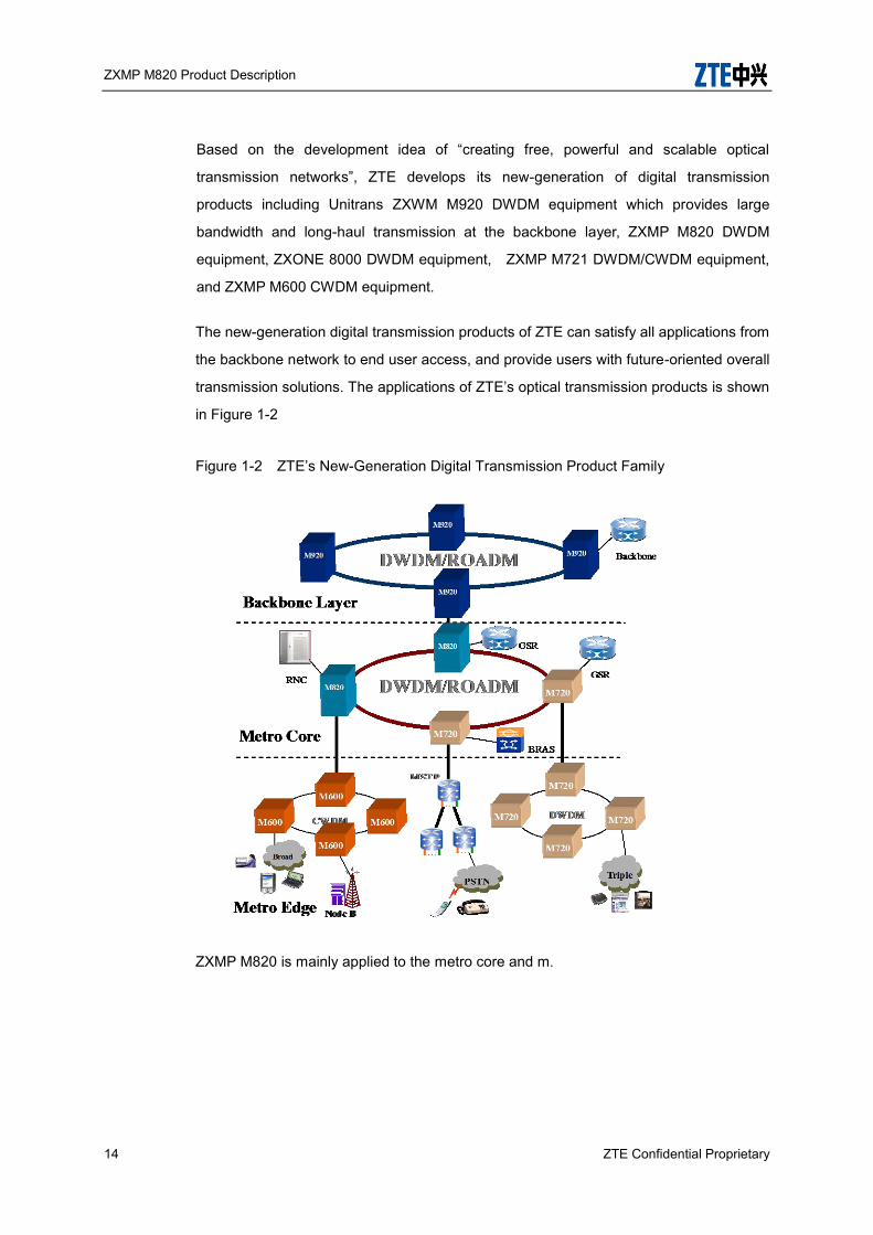
The new-generation digital transmission products of ZTE can satisfy all applications from
the backbone network to end user access, and provide users with future-oriented overall
transmission solutions. The applications of ZTE’s optical transmission products is shown
in Figure 1-2
Figure 1-2 ZTE’s New-Generation Digital Transmission Product Family
ZXMP M820 is mainly applied to the metro core and m.
ZXMP M820 Product Description
ZTE Confidential Proprietary 15
2 Highlight Features This chapter introduces the salient features of ZXMP M820.
2.1 Large Capacity and Easy Upgrade
ZXMP M820 can provide 1.92/3.84/8Tbit/s transmission capacity, fully satisfying the
ever-growing requirements on bandwidth. The system is designed with modular structure
and multi-rack management technology. It can be smoothly upgraded to 192-wavelength.
Its good scalability and expansibility can protect user’s investment maximally.
2.2 Single 100Gbit/s system
ZXMP M820 can support single 100Gbit/s system, and has following features:
Support 80 wavelengths
Support 80*100GE transmission and the capacity of at most 8T
PM-QPSK Coherent Rx modulation for ULH transmission
PM-QPSK Coherent Rx coding with SD-FEC has good OSNR tolerance and can
restrain the non-linear effect well. It can reach over 1500KM without the REG with
50GHZ spacing.
Embedded high-speed DSP technology realizes the compensation of dispersion
and PMD, so that the additional boards of PMD and CD compensation are reduced.
PM-QPSK coding can restrain the non-linear effect well. With DSP technology, the
PMD tolerance can support 30ps and CD tolerance can support +/-50000ps/nm.
2.3 Single 40Gbit/s system
ZXMP M820 can support single 40Gbit/s system, and has following features:
ZXMP M820 Product Description
16 ZTE Confidential Proprietary
Support 96 wavelengths
Support 80/96*40G transmission and the capacity of at most 3.84T;
P-DPSK and RZ-DQPSK modulation for ULH transmission
Improved DPSK coding has good OSNR tolerance and can restrain the non-linear
effect well. It can reach 1500KM without the REG with 50GHz spacing.
RZ-DQPSK coding has good PMD tolerance and can restrain the non-linear effect
well. It can reach 2000KM without the REG with 50GHZ spacing.
Embedded TODC and EDFA and the same dispersion tolerance & power budget as
10G system.
OTU board is embedded with TODC and EDFA, the system allows the biggest
dispersion tolerance of -700ps/nm ~+700ps/nm, and the dispersion tolerance &
power budget are the same as 10G system.
Ultra high integration
40G board only needs 2 slots, with high integration and low power consumption.
Single rack supports 21×40G wavelengths.
For the OTN electrical cross-connection subsystem, this supports 2*40G in a single
slot for client side and 1*40G in a single slot for line side.
Smooth network upgrade
The 40G board can plug and play in the legacy equipment because the system is
developed on the existing WDM platform. It supports smooth upgrade from 10G to
40G without any service interruption.
2.4 Super-long-haul Transmission
With different optical transponder units (OTU), EDFA, FEC, AFEC and SD FEC
technologies, RZ/SRZ coding technology, P-DPSK/DQPSK/PM-QPSK coding
technology, distributed Raman amplifier(RAMAN), Remote pumped optical amplifier

ZXMP M820 Product Description
ZTE Confidential Proprietary 17
(RPOA) and dispersion management technology, ZXMP M820 can perform super long
non-electric relay transmission from several kilometers up to thousands of kilometers.
2.5 Multi-service Access Mode
ZXMP M820 adopts an open design. The accessed optical signals can be converted to
ITU-T G.692 recommendation compliant wavelength signals for output by employing
optical/electric/optical conversion technology.
It supports transparent transmission of optical signals in multiple formats, such as
STM-N (N=1, 4, 16, 64,256), POS, GE/10GE/100GE, OTU1/2, ATM, ESCON,
FICON,DVB and FC, which protect users’ benefit and provide an ideal means for network
expansion.
ZXMP M820 also can multiplex low-rate services into 100GE, 40G, 10G or 2.5G rates
transparently to improve the availability of system wavelength.
2.6 Flexible networking modes
Functionality of ZXMP M820 can be changed from OLA to OADM to OTM by choosing
different combination of functional modules, making it more flexible for complicated
network topologies, such as chain, star, cross, tangent-ring and mesh networks.
2.7 Wavelength Add/Drop Functions
Filters in the ZXMP M820 can be configured flexibly to implement the adding/dropping of
1 to 80 wavelengths. With this kind of design, the ZXMP M820 supports both the FOADM
and the ROADM functions.
FOADM: This function is to implement the adding/dropping of fixed wavelengths.
ROADM: With this function, wavelengths to be added/dropped can be reconfigured.
Besides, add/drop ports can be assigned to these wavelengths flexibly, that is the
port-assignment function. ZXMP M820 support ROADM function based on WSS

ZXMP M820 Product Description
18 ZTE Confidential Proprietary
technologies.
2.8 Reliable Protection Functions
ZXMP M820 can provide multiple and effective protection modes: Optical subnet
connection protective switchover(OSNCP); Unidirectional optical line protective
switchover (ULSR); Unidirectional optical channel protective switchover(UPSR);
Bidirectional optical line share protective switchover (BLSR); Bidirectional optical
channel share protective switchover(BPSR) etc. which with the switching time shorter
than 50ms. When ZXMP M820 is configured as OADM node on a ring network, route
protection of channels can be accomplished.
2.9 Performance Monitoring Technology
ZXMP M820 uses a board performance monitoring unit to capture board performance
data, which can be viewed to accurately locate a fault via NMS.
2.10 Power Management Technology
ZXMP M820 adopts excellent power management technology to adjust and control the
power and power spectrum at each point in the system.
ZXMP M820 system supports LAC(line attenuation control), APC(automatic power
control), AGC(automatic gain control) etc. technologies. The gain adjustment range of
LAC card is: 2-26dB; the gain adjustment range of general optical amplifier is ±5dB
which can both be adjusted via NM.
APC and AGC technologies can control the launched power/gain on MS level to ensure
hitless in-service insertion or removal of channels.
2.11 Powerful NM
NetNumenTM U31 (BN), adopted by ZXMP M820, can manage CWDM, DWDM, SDH,
ZXMP M820 Product Description
ZTE Confidential Proprietary 19
PTN and Data equipments. The new generation network management system on NE
management layer/ subnet management layer is used to manage and supervise NE
equipment in the bearer network (BN).
Based on OSPF algorithm, the NMS has ECC automatic route function, that is to say the
ECC route between NEs can be set up automatically without manual configuration,
which could make the networking application easily and fast.
In addition, the NMS supports remote and online upgrade of NE software and board
software, provides management at multiple layers, i.e. NE layer, NE management layer
and network management layer, and offers the fault management, performance
management, security management, configuration management, maintenance
management and system management.
2.12 WASON
ZXMP M820 supports GMPLS/WASON control plane load, and has following features:
Rapid automatic route discovery
Strong ability for automatic resource discovery
Versatile resource management functions
Fast end-to-end service provisioning
Multi-level SLA
Standard technology and open platform
Flexible equipment upgradeability
Highly operable and maintainable
ZXMP M820 Product Description
20 ZTE Confidential Proprietary
3 Functionality This chapter introduces the functions of ZXMP M820 in detail, including transmission,
ultra-long-haul distance transmission, power management, performance test, dispersion
management, service capability, communication monitoring, alarm input/output and
protection.
3.1 Functions
3.1.1 Large Transmission Capacity
Transmission system less than 48-wavelength employs on the C band with 100
GHz channel spacing.
80/96-wavelength transmission system employs on the C band via inter-leaver
technology with 50 GHz channel spacing.
3.1.2 Ultra-long-haul Distance Optical Source
ZXMP M820 employs the ultra-long-haul distance optical source technologies including
forward error correction (FEC) coding, advanced out band FEC coding, soft-decision (SD)
FEC coding, RZ code pattern and self-adaptive receiving.
FEC technique
i Description
FEC is a signal data processing technique. At the transmitting end, it sends the data with
the redundant code generated by the specific algorithm, while, at the receiving end,
according to the relevant algorithm, it checks and corrects the bit errors occurring during
transmission with the redundant codes, and restores the original signals.
ii Features
Improve the error tolerance capability of the transmission signals to reduce signal/noise
ratio required by the system, and extend the transmission distance.

ZXMP M820 Product Description
ZTE Confidential Proprietary 21
The conventional FEC based on G.709 can increase the OSNR tolerance about 5~6 dB,
and the advanced FEC technique adopting more effective coding algorithm can increase
the OSNR tolerance about 7~9dB.
PM-QPSK Coherent Rx modulation for ULH transmission
PM-QPSK Coherent Rx coding with SD-FEC has good OSNR tolerance and can
restrain the non-linear effect well. It can reach over 1500KM without the REG
with 50GHZ spacing. Return to zero (RZ) technique
RZ code allows higher peak value of power than NRZ code, and the mean transmitting
optical power of RZ and NRZ code are on the same level, so it improves the signal/noise
ratio for receiving signals of the system.
And RZ code reduces signal power spectral density to effectively suppress non-linear
impact during transmission, so RZ code is more suitable for ultra-long-haul transmission.
Super RZ (SRZ) technique
With lower spectrum power density and higher suppression of the non linear effect than
RZ technique, the OSNR tolerance of back to back is less than 9dB, so it is suitable for
the long-haul or super long-haul transmission distance.
Self-adaptive receiving technology
The receiver adjusts the judgment point level and phase automatically according to the
signal receiving conditions, in order to obtain a higher Q value and lower bit error rate.
3.1.3 Optical Amplifier
Optical fiber amplifier of ZXMP M820 system is based on single-stage mode or
double-stage mode. Enhanced Optical Booster Amplifier (EOBA),,Enhanced Optical
Line Amplifier (EOLA) and Enhanced Optical Preamplifier (EOPA) is based on
single-stage mode , and Enhanced Optical Node Amplifier(EONA) is based on
double-stage mode. EOBA,,EOLA and EONA use dual pumps, and EOPA use single
pump or dual pumps. The wavelength of single pump source is 980nm, and the
wavelengths of dual pump sources are 980nm and 1480nm. Gain flatness is ±1dB. Extra
metal ion and Gain Flattening Filter (GFF) can be added to ensure OA gain flatness.

ZXMP M820 Product Description
22 ZTE Confidential Proprietary
Characteristics of dual/single pump source of EDFA are shown as below:
Table 3-1 Characteristics of dual/single pump source
Quantity of pump source
Wavelength Output power
Power stability
Power stableness technique
Dual pumps
980nm 100-150mW ±0.02dB Automatic gain control
1480nm 200-350mw ±0.02dB Automatic gain control
Single pump
980nm 100-150mW ±0.02dB Automatic gain control
ZXMP M820 employs ultra-long-haul distance technologies, such as RAMAN amplifier
and large power EDFA. Working principles of Raman amplifier (RA) are shown as
following:
Figure 3-1 Principles of RA
Compared with EDFA, the RAMAN fiber amplifier enjoys low noise merit. The equivalent
noise factor of the distributed RAMAN amplifier board (DRA) of ZXMP M820 is 0 dB, and
switching gain is 10 dB.
ZXMP M820 also provides large power EDFA, which directly improves OSNR to extend
the transmission distance.
3.1.4 Power Management
To guarantee the network performance, ZXMP M820 adopts power management
technology to adjust and control the power and power spectrum at each point in the

ZXMP M820 Product Description
ZTE Confidential Proprietary 23
system.
Intelligent Power Management
The intelligent power management is implemented by the line attenuation card (LAC),
optical amplifier board and EMS. It can detect the changing state of the optical line power
and make relevant adjustments accordingly, so as to maintain the receiving power and
OSNR ratio at the normal value during ZXMP M820’s operation.
Attenuation of LAC can be adjusted from 2dB to 26dB. And attenuation of LAC with
attenuation slope compensation can be adjusted from 5dB to 26dB. The gain of optical
amplifier in ZXMP M820 system can be adjusted via NM, and the typical range is ±5dB.
ZXMP M820 can provide APR or APSD protection process, that is, the EDFA
automatically reduces the power or switches off the power in case of no input light, so as
to make operator safety.
Protection process is fulfilled as follows:
i. Optical power supervision device detects signal loss at active optical channel.
ii. Reversing pump of RA shuts down.
iii. Co-directional EDFA output at downstream node of breakpoint remains (APR)
or shuts down (APSD).
iv. Inverse EDFA at downstream node of breakpoint shuts down and
automatically checks system recovery in intervals specified.
v. Inverse EDFA output at upstream node of breakpoint remains (APR) or shuts
down (APSD).
vi. Co-directional EDFA at upstream node of breakpoint shuts down and
automatically checks system recovery in intervals specified.
vii. After bidirectional fibers of the system recover, the output of EDFA and RA at
the transmission section of breakpoint returns to normal.
In ZXMP M820 system, RA can automatically shut down and manually restart.
ZXMP M820 Product Description
24 ZTE Confidential Proprietary
Auto Performance Optimization
When APO (Auto Performance Optimization) is adopted, the power management
subsystem plane can intelligently adjust LAC and EDFA gain to automatically optimize
and manage DWDM system parameters such as optical power and OSNR.
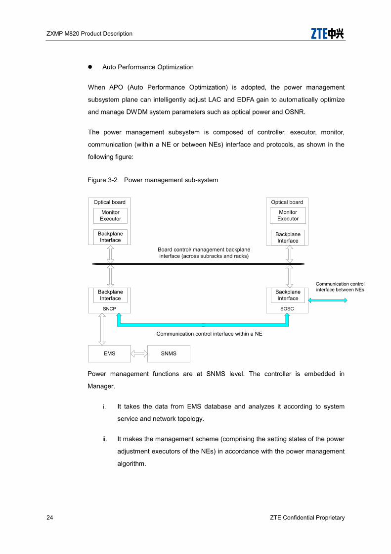
The power management subsystem is composed of controller, executor, monitor,
communication (within a NE or between NEs) interface and protocols, as shown in the
following figure:
Figure 3-2 Power management sub-system
SNCP SOSC
EMS SNMS
Optical board Optical board
Monitor Executor
Monitor Executor
Backplane Interface
Backplane Interface
Backplane Interface
Backplane Interface
Board control/ management backplane interface (across subracks and racks)
Communication control interface within a NE
Communication control interface between NEs
Power management functions are at SNMS level. The controller is embedded in
Manager.
i. It takes the data from EMS database and analyzes it according to system
service and network topology.
ii. It makes the management scheme (comprising the setting states of the power
adjustment executors of the NEs) in accordance with the power management
algorithm.

ZXMP M820 Product Description
ZTE Confidential Proprietary 25
iii. It supplies the scheme to the operator to view, and then sends it to the NEs to
optimize the power.
The network power optimization starts under the command of auto performance
optimization. After the automatic optimization completion, it can be executed with the
operator’s approval.
The automatic power management starts after operation, and monitors the system
performances. It can handle a fault automatically, store and display the result.
3.1.5 Performance Detection Function
ZXMP M820 systems can provide OPM to supervise optical parameters at each optical
channel, e.g., optical channel power, central wavelength and OSNR. It can supervise
active optical channel in real time without disconnecting services, send related data to
NMS and check the associated physical quantity at NM in two view modes: illustration
and data. Measurement precision of central wavelength is ±0.1nm, power ±1.0dB and
OSNR ±1.5dB.
OPM functions are shown as following:
Supervise path wavelength, optical power and OSNR of WDM signals in real-time.
Automatic self-calibration.
Supervise four channels of input optical signals (with optical switch);
Process data on boards, and find out power, wavelength and OSNR at peak points.
If OPM is not configured, NMS can supervise OA and OTU input and output power.
Precision of optical power is ±1dB.
The OTU part has performance monitoring and overhead processing functions,
which can accurately locate faulty point and type by layer.
OTN layer: Monitor loss of frame alarm (OTUk-LOF) and bit interleaver parity check
(OTUk-BIP8), and process overhead SM-TTI.
SDH signal: Monitor and check B1, B2 and J0 bytes.
ZXMP M820 Product Description
26 ZTE Confidential Proprietary
GE signal: Monitor and collect error packets and error packet rate statistics.
ZXMP M820 equipment provides monitoring port in each board for the carrier to test and
monitor the signal quality by accessing the apparatus.
3.1.6 OTN Description
In OTN architecture, the OTH (Optical Transport Hierarchy), which is based on the ITU-T
G.709 Recommendation, can be adopted to build a flexible transmission sub-layer. At
present, the OTH provides electronic cross-connect and convergence for ODU1
(2.5Gbit/s) and ODU2 (10Gb/s), which helps to improve wavelength utilization.
The G.709-based OTN provides rich overhead resources and enables strong
management ability on the optical layer. OTN maintenance signals are used for fault
isolation and alarm suppression, which greatly reduces system maintenance burden.
In a configurable optical network, powerful monitoring management is very important.
Carriers always find that data signals cannot be properly received, though the optical
power of the receiving end is normal. The TCM overhead on the ODU (Optical
Demultiplexer Unit) layer supports trans-domain or trans-network end-to-end optical
channel monitoring and management; together with optical channel detection technology,
it enables optical power monitoring, alarm correlation check, fault location, QoS
confirmation, and protection switchover triggering.
The OTU boards of ZXMP M820 comply with G.709 recommendations. M820 supports
OTN overhead detection and processing such as OTUk/ODUk/OPUk-based LOF
detection, multi-frame detection, FEC performance detection and SM/PM/TCM/PT
overhead detection which enable precise fault location and easy network maintenance
management.
ZXMP M820 supports electrical cross-connect based on
ODU0/ODU1/ODU2/2e/ODU3/3e2 which can achieve sub-wavelength grooming.
3.1.7 Dispersion Management
Dispersion restrictions must be taken into consideration in long-haul transmission for
10G and 40G system. Certain amounts of the dispersion compensation modules are

ZXMP M820 Product Description
ZTE Confidential Proprietary 27
configured in the dispersion compensation plug-in box (DCM) of ZXMP M820 on actual
demands.
By configuring the values of line compensation, pre-compensation and
post-compensation reasonably, the system could actualize the balance compensation,
as shown in Figure 3-3
Figure 3-3 Dispersion management
3.1.8 Service Functions
Service Access Function
ZXMP M820 can access the following services:
SDH services including STM-1/4/16/64/256
SONET services including OC-3/12/48/192/768
ATM or POS services including VC4, VC4-4c and VC4-16c
Ethernet services including FE, GE, 10GE, 100GE
Enterprise intranet services such as ESCON, FICON, DVB and FC.
Any rate services between 34Mbit/s ~ 2.67Gbit/s
Service Convergence Function
ZXMP M820 can converge and de-multiplex the low rate signals.
Each SRM42 board converge 4 STM-1/4 SDH signals or ATM signals to STM-16

ZXMP M820 Product Description
28 ZTE Confidential Proprietary
signal.
Each SRM41 board converge 4 STM-16 SDH signals or ATM signals to STM-64
signal.
Each MQT3 board converge 4 STM-64/OC-192/10GE/OTU2 signals to OTU3
signal.
Each MX2 board converge 10 STM-64/OC-192/10GE/OTU2 signals to OTU4
signal.
Each SDSA/GEM2/GEMF board converge 2 GE signals to 2.5Gbit/s rate.
Each MOM2 board converge 8 GE/FC or 4* 2GFC or 4*2.5G to OTU2 signal.
DSA board implements the multiplexing/demultiplexing between eight data service
signals at tributary side and two STM-16 signals at aggregate side.
MQA1 board can access four channels of any rate service ranging from 100Mbps to
2.67Gbps, the typical types of services include STM-1/4/16(OC-3/12/48),OTU1,
FE/GE, 1G/2GFC, DVB_ASI/ESCON/FICON/HDTV, PDH.
MQA2 board can access four channels of any rate service ranging from
1.0625Gbps to 4.25Gbps.
MJA board can upgrade smoothly from 4 to 10 any rate service access on client
side by collaborating with MQA1, and can upgrade smoothly from 4 to 22 any rate
service access on client side by collaborating with MQA2. MJA supports any rate
service from 100Mbps to 2.67Gbps.
It is applicable to different networking conditions by selecting tributary modules and
aggregation module type.
3.1.9 Wavelength Add/Drop Function
The ZXMP M820 supports the adding/dropping of wavelengths in the granularity of 1
wavelength, 4 wavelengths or 8 wavelengths. The quantity of wavelengths to be
added/dropped can be expanded from 1 to 80.
ZXMP M820 Product Description
ZTE Confidential Proprietary 29
An optical add/drop multiplexer subsystem can be configured as a fixed one (FOADM) or
a reconfigurable one (ROADM).
FOADM: In such subsystem, OAD board is needed to add/drop fixed wavelengths in the
system.
ROADM: In such subsystem, additional WBU or WSU board is needed. Configure the
system in the EMS to implement the adding/dropping and direct transmission of any
specified wavelengths in the same direction. Moreover, the ROADM subsystem provides
the port assignment function, with which wavelengths can be added/dropped through
assigned ports.
In ROADM subsystems, it is unnecessary to adjust fibers manually when the quantity of
wavelength to be added/dropped changes or some other wavelengths need to be
added/dropped.
3.1.10 Communication and Monitoring Functions
The supervision and communication subsystem of ZXMP M820 is composed of SNP,
SOSC and SEI boards.
The functions are:
Main control board (SNP)
SNP board is used as an NE control processor in the supervision subsystem
implementing NE-level network management function. SNP board provides the following
functions:
Provides S interfaces that are used to communicate with the other boards in an
NE, collect and process alarm and performance messages of the other boards, and
report to the EMS.
Stores configuration data of an NE. After configuration, SNP boards can work
independently without the EMS.
Provides Qx interfaces for upper-layer management system. In the supervision
subsystem, Qx interface is provided by SEI board.

ZXMP M820 Product Description
30 ZTE Confidential Proprietary
Implements Automatic Protection Switch (APS) function to ensure that the
communication speed of APS data meets the requirement of the APS conversion
time.
When optical supervision channel fails, SNP board ensures the transfer and
exchange of supervision information through standby route (accessed via SOSC
board).
Provides alarm input/output signals for SEI board, through which output the
alarms to head cabinet or other user alarm equipments.
Provides management function for multiple racks. An SNP board can manage
16 racks, that is, 1 master rack and 15 slave racks.
Provides SD card to store EMS historical data.
PCB board provides RJ45 interface to facilitate the board de- bugging. The
panel provides RS232 interface to output the board debugging information.
Supports the online update of board software.
Optical supervision channel card (SOSC)
SOSC board is used in 100M supervision systems to implement the transmission and
exchange of ECC data, channel data of order and transparent user, and APS information.
The main functions are described as follows:
In 100 M supervision system, pack the data between NEs in the form of IP
packet, such ECC data, APS data, transparent user channel data and order voice
data. And transmit and exchange all these data in the Ethernet data frame.
The SOSC board provides three 10/100BASE-T Ethernet electric interfaces
with the automatic cross function (the physical interface is provided by SEI board).
The SNP board, EMS, slave SOSC board and backup route are accessed by these
interfaces to implement the supervision information exchange within the NEs.
The front panel of SOSC board provides four 100BASE-FX Ethernet optical
interfaces to access 1510 nm supervision channel and realize the supervision

ZXMP M820 Product Description
ZTE Confidential Proprietary 31
information transmission between the NEs. 100BASE-FX is an optical interface with
the rate at 100Mbit/s.
Based on the board hardware, the SOSC board provides the capability to
transmit supervision information within the three-level.
The SOSC board adopts OSPF protocol to dynamically search the route.
Extension Interface Board (SEIA)
SEIA board is used to lead various external interfaces and cascaded interface of
sub-rack to the panel for connection. The functions are described as follows:
Provides four FE Ethernet interfaces to be used as Qx interface to connect to
the EMS computer, or as the transparent user channel interface and IP phone
interface based on Ethernet.
Provides a 26–pin interface for external alarm input.
Provides a 15–pin interface for external alarm output, alarm LED or ringing
output.
Provides a 15–pin alarm cascaded interface.
Provides alarm ring switch.
Through the 100Mb/s Ethernet technologies, the 100Mbit/s supervision system
encapsulates ECC data, APS data, transparent user channel data, and order wire voice
data in IP packets, and transmits/exchanges them in the Ethernet data frame. The 100
Mb/s supervision systems can increase communication bandwidth between control
boards in the NE, and reduce quantity and type of backplane buses.
The position of supervision subsystem is shown in Figure 3-4

ZXMP M820 Product Description
32 ZTE Confidential Proprietary
Figure 3-4 Position of supervision subsystem
3.1.11 Time/Clock Synchronization Service
ZXMP M820 supports clock and time synchronization. It meets the requirements of the
3G base station for precise time synchronization.
By abstracting clock information from serial stream of transmission link physical path, the
clock synchronization mechanism in the physical layer can realize synchronous
frequency.
Time synchronization follows IEEE 1588 V2 protocol. ZXMP M820 provides out-of-band
1pps+TOD and FE time synchronous interface to realize out-of-band time transmission.
Time synchronization service supported by ZXMP M820 includes:
Use BMC algorithm to choose clock. BMC (Best Master Clock) algorithm
decide clock source by comparing descriptive data of two or more clocks.
Support OC, BC and TC.
Support clock and time SSM processing.
Support latency compensation service
Support switchover of active and standby clock sources.
ZXMP M820 Product Description
ZTE Confidential Proprietary 33
SEIA2 card installed in CX sub-rack provides the input/output of 2M Hz or 2M bits clock.
The selection of analog or digital clock is realized by the switch. M2SEIA2 supports two
groups of clock input or output.
3.1.12 Alarm Input /Output Function
Alarm input function
ZXMP M820 uses the optical coupler isolation signal to access the alarm inputted
by the external monitoring equipment, and displays it on the NMS through the
ALARM_IN interface on the SEIA board.
The system can access 10 external alarms at most. The alarm type can be set
through the NMS for detection of external environment alarms, such as fan, doors
and temperature.
Alarm output function
The equipment alarm is outputted to the WARN interface in the SEIA board and
then outputted to the monitoring display cabinet or other monitoring units in the
equipment room via the ALARM_OUT interface of the SEIA board. Signals are
isolated by relays.
3.1.13 System Level Protection
OTU board 1:N protection
The WDM networks generally require spare OTU boards and elements. When
configured in protective mode, spare part can realize real-time protection, which is
much quicker, safer and saves maintenance cost.
1:N protection only need to configure OTU and OMCP units at both ends of OTM,
and may utilize the spare OTU board also, which has a low cost.
The processes are shown in Figure 3-5
ZXMP M820 Product Description
34 ZTE Confidential Proprietary
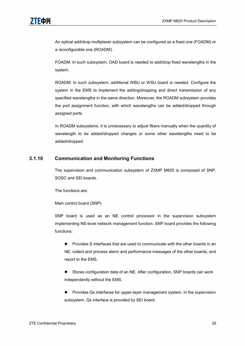
Figure 3-5 The Block Diagram of Optical Path 1: N Protection Function
When several paths of services are faulty simultaneously, it is required to protect
the services with higher priority set in the NMS. One OMCP board can perform 1: 8
protections.
Common Units Protection
Firstly, ZXMP M820 supports 1+1 power protection on the sub-rack with two power
inputs. The sub-rack power module SPWA fulfills reverse connection prevention,
soft start, balance and supervision of two power inputs. The information is sent to
Power Distribution Unit on the top of rack for processing and reporting to NM via
alarm cable.
Secondly, ZXMP M820 supports 1+1 SNP board protection, so that guarantee the
communication among all the boards in the NE, and Implements various functions,
such as control, communication and GMPLS protocol processing more security.
Thirdly, ZXMP M820 supports ring protection for the inner-connection of sub-racks,
so that avoids the communication interruption between sub-racks. .
3.1.14 Network level Protection
Optical Path 1+1 Protection
i Protection principles
The optical path 1+1 protection is implemented with the OP board, by sending
concurrently and receiving selectively in both working path and protection path.
ii Applications

ZXMP M820 Product Description
ZTE Confidential Proprietary 35
One OP board is used to protect a pair of bidirectional services with the same
wavelength. Under the 1+1 protection case, the number of OP boards configured is
the same as that of protected channels.
iii Chain networking
The protection path and the protected path are transmitted in the same fiber. On the
chain networking, 1+1 protection can only perform equipment protection instead of
route protection, as shown in Figure 3-6
Figure 3-6 Optical Path Layer 1+1 Protection (Chain Networking)
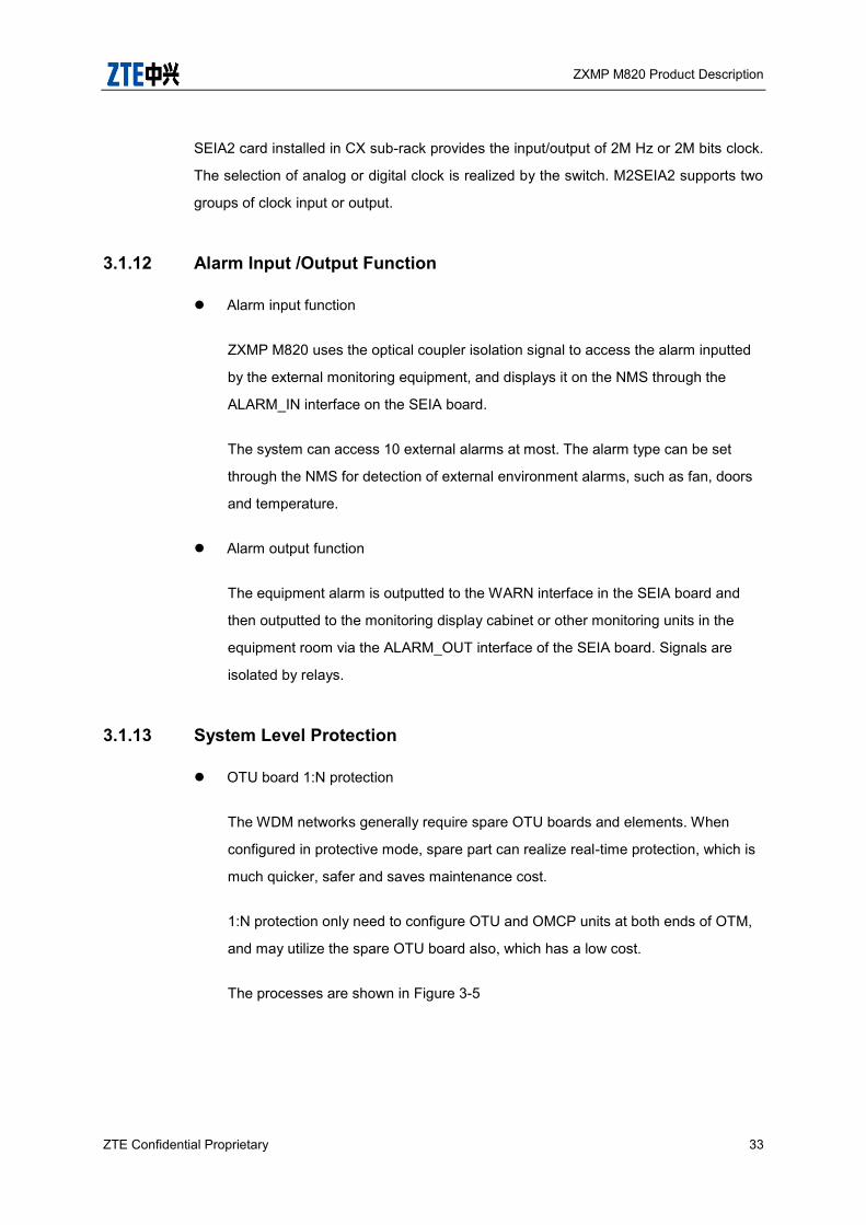
iv Ring networking
On the ring networking, the protection path and the protected path reach the
receiving end through different paths. 1+1 path protection can protect both route
and the equipment. The ring networking is shown in Figure 3-7.
ZXMP M820 Product Description
36 ZTE Confidential Proprietary
Figure 3-7 Ring Networking
A
B
C
D
Protection path
Work path
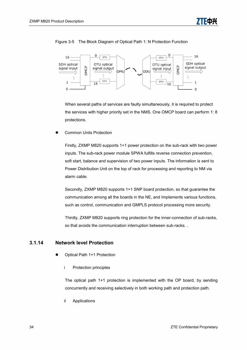
MS 1+1 Protection
The MS 1+1 protection of ZXMP M820 adopts 1+1 protection mode section by section,
as shown in Figure 3-8.
Figure 3-8 Functional Block Diagram for MS 1+1 Protection
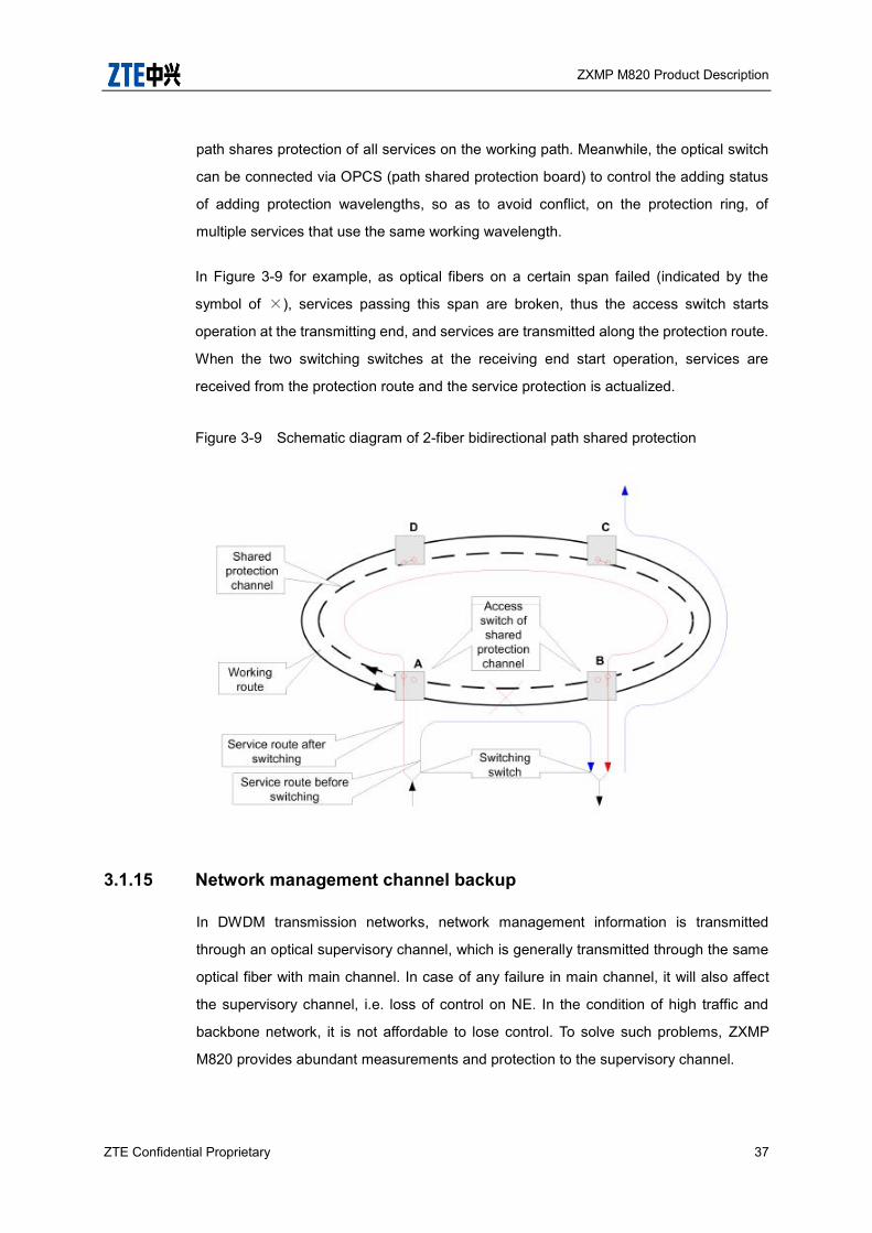
2-fiber bidirectional path shared protection
In the 2-fiber bidirectional path shared protection ring, λ1 of the external ring forms the
working path, and λ1 of the internal ring forms the protection path. The working path
allows wavelength multiplexing of multiple unidirectional services, and the protection
ZXMP M820 Product Description
ZTE Confidential Proprietary 37
path shares protection of all services on the working path. Meanwhile, the optical switch
can be connected via OPCS (path shared protection board) to control the adding status
of adding protection wavelengths, so as to avoid conflict, on the protection ring, of
multiple services that use the same working wavelength.
In Figure 3-9 for example, as optical fibers on a certain span failed (indicated by the
symbol of ×), services passing this span are broken, thus the access switch starts
operation at the transmitting end, and services are transmitted along the protection route.
When the two switching switches at the receiving end start operation, services are
received from the protection route and the service protection is actualized.
Figure 3-9 Schematic diagram of 2-fiber bidirectional path shared protection
3.1.15 Network management channel backup
In DWDM transmission networks, network management information is transmitted
through an optical supervisory channel, which is generally transmitted through the same
optical fiber with main channel. In case of any failure in main channel, it will also affect
the supervisory channel, i.e. loss of control on NE. In the condition of high traffic and
backbone network, it is not affordable to lose control. To solve such problems, ZXMP
M820 provides abundant measurements and protection to the supervisory channel.

ZXMP M820 Product Description
38 ZTE Confidential Proprietary
In ring network, when certain section fails (e.g. optical fiber damage) in a certain direction,
network management information automatically switch to the optical supervisory channel
in the other direction of the ring without affecting the management of the whole network.
In chain network, the situation is more critical, because breakage in optical fiber means
breakage of supervisory channel. Consequently, network management administrators
are unable to get the supervisory information of failed station. To avoid this accident,
network management information should use the backup channel. By using data
communication network (DCN) and routers, ZXMP M820 can provide backup network
management channel.
When the network is normal, network management information is transmitted over the
main supervisory channel, as shown in Figure 3-10
Figure 3-10 Network management through supervisory channel
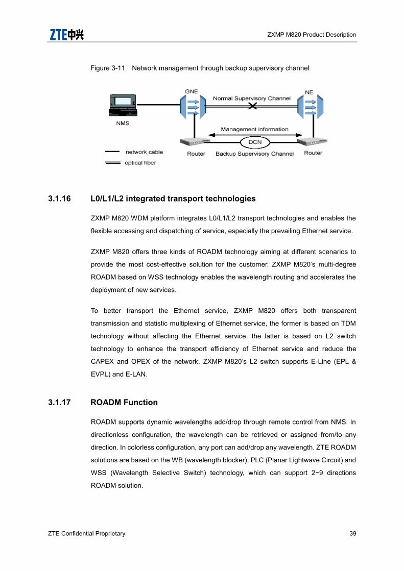
On the failure of main supervisory channel, network elements automatically switch the
management information to the backup channel to guarantee that the network
management system can supervise and operate the entire network, as illustrated in the
Figure 3-11
ZXMP M820 Product Description
ZTE Confidential Proprietary 39
Figure 3-11 Network management through backup supervisory channel
3.1.16 L0/L1/L2 integrated transport technologies
ZXMP M820 WDM platform integrates L0/L1/L2 transport technologies and enables the
flexible accessing and dispatching of service, especially the prevailing Ethernet service.
ZXMP M820 offers three kinds of ROADM technology aiming at different scenarios to
provide the most cost-effective solution for the customer. ZXMP M820’s multi-degree
ROADM based on WSS technology enables the wavelength routing and accelerates the
deployment of new services.
To better transport the Ethernet service, ZXMP M820 offers both transparent
transmission and statistic multiplexing of Ethernet service, the former is based on TDM
technology without affecting the Ethernet service, the latter is based on L2 switch
technology to enhance the transport efficiency of Ethernet service and reduce the
CAPEX and OPEX of the network. ZXMP M820’s L2 switch supports E-Line (EPL &
EVPL) and E-LAN.
3.1.17 ROADM Function
ROADM supports dynamic wavelengths add/drop through remote control from NMS. In
directionless configuration, the wavelength can be retrieved or assigned from/to any
direction. In colorless configuration, any port can add/drop any wavelength. ZTE ROADM
solutions are based on the WB (wavelength blocker), PLC (Planar Lightwave Circuit) and
WSS (Wavelength Selective Switch) technology, which can support 2~9 directions
ROADM solution.
ZXMP M820 Product Description
40 ZTE Confidential Proprietary
ROADM provides node reconfiguration, implements connection between any two nodes,
wavelength-level add/drop and pass-through configuration without manual intervention,
thus addressing service demands and cutting operation & maintenance cost. In addition,
the adoption of ULH WDM techniques greatly reduces full-band service terminations and
undesirable O-E regeneration, enabling a highly scalable network, and saving equipment
investment. With ROADM, multi-ring, mesh and star can be formed flexibly, adapting to
dynamic characteristics and networking requirements for future service networks.
ZXMP M820 supports colorless and directionless ROADM solutions which are the most
flexible. Colorless means any wavelength can be assigned to any port. Directionless
means any direction can be assigned to any port.
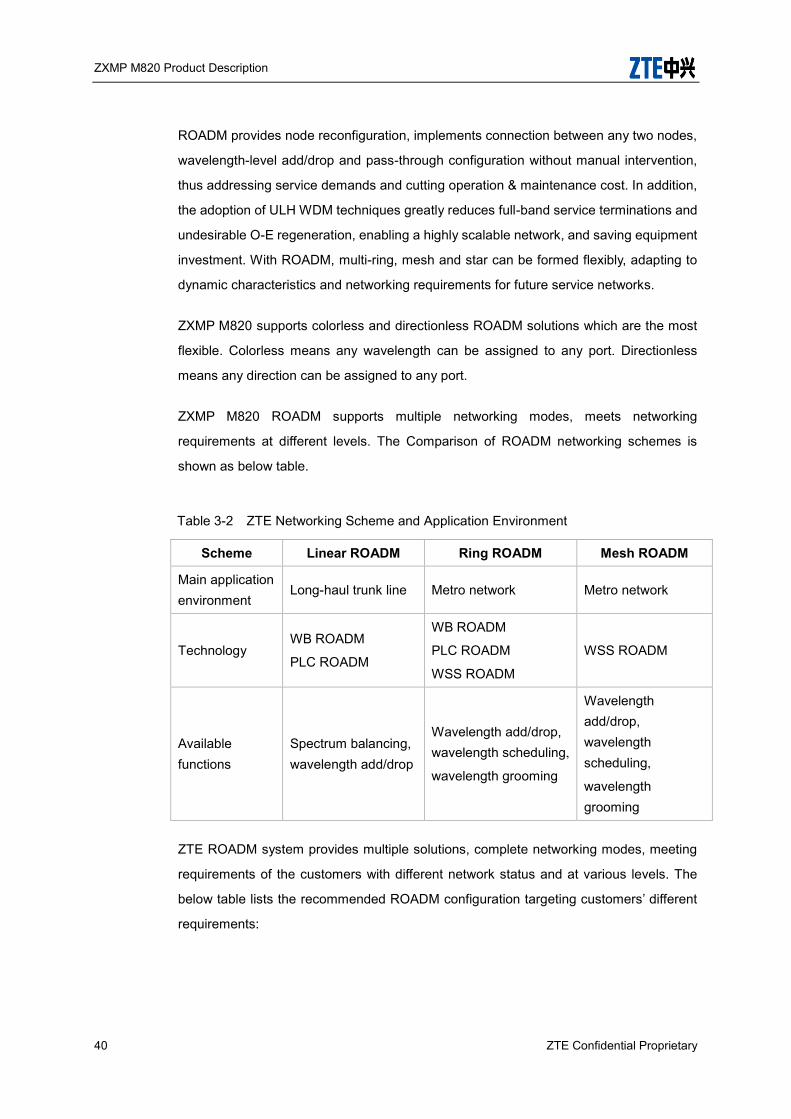
ZXMP M820 ROADM supports multiple networking modes, meets networking
requirements at different levels. The Comparison of ROADM networking schemes is
shown as below table.
Table 3-2 ZTE Networking Scheme and Application Environment
Scheme Linear ROADM Ring ROADM Mesh ROADM
Main application environment
Long-haul trunk line Metro network Metro network
Technology WB ROADM
PLC ROADM
WB ROADM
PLC ROADM
WSS ROADM
WSS ROADM
Available functions
Spectrum balancing, wavelength add/drop
Wavelength add/drop, wavelength scheduling,
wavelength grooming
Wavelength add/drop, wavelength scheduling,
wavelength grooming
ZTE ROADM system provides multiple solutions, complete networking modes, meeting
requirements of the customers with different network status and at various levels. The
below table lists the recommended ROADM configuration targeting customers’ different
requirements:

ZXMP M820 Product Description
ZTE Confidential Proprietary 41
Table 3-3 ZTE/ ROADM Solutions
Solution Characteristics Target customer
WSS ROADM with tunable port in add channel
Add/drop wavelengths can be provisioned randomly, wavelength grooming flexibly.
Uncertainty in service growth, large traffic of future services, or requiring extremely high network flexibility and wavelength route.
WSS ROADM with fixed port in add channel
Add/drop wavelengths are fixed, supports complex network architecture in the future.
Services are relatively fixed, future networks may evolve towards Mesh.
PLC ROADM with fixed port in add/drop channels
Add/drop wavelengths are fixed, the cost is low.
Services are relatively fixed, future services are predictable.
WB ROADM with fixed port in add/drop channels
Add/drop wavelengths are fixed, the cost is low.
Services are relatively fixed, future services are predictable.
3.1.18 Electrical Cross-Connect Function
Electrical Cross-Connect system can access data services including GE, FC, FICON,
ESCON, SDH and DVB. The services can be aggregated into multiple ODUk services on
the tributary convergence board and be cross connected at a granularity of
ODU0/1/2/2e/3/3e2. Then the cross connected signals are aggregated into OTU2/OTU3
on the group convergence board and are eventually output from the line-side interface.
Electrical Cross-Connect system is categorized as centralized or distributed switching
platform in Figure 3-12
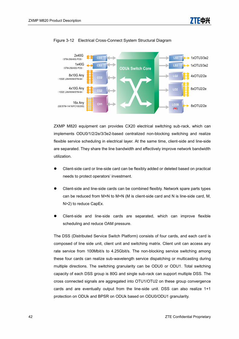
ZXMP M820 Product Description
42 ZTE Confidential Proprietary
Figure 3-12 Electrical Cross-Connect System Structural Diagram
16x Any(GE/STM-1/4/16/FC100/200)
CS3
8x10G Any(10GE LAN/WAN/STM-64)
CH1
1x40G(STM-256/40G POS)
CO2
CD3
ODUk Switch CoreLS3 1xOTU3/3e2
LO2B(PIC)
8xOTU2/2e
LO2 8xOTU2/2e4x10G Any(10GE LAN/WAN/STM-64) CQ2
2x40G(STM-256/40G POS)
LQ2 4xOTU2/2e
LS3 1xOTU3/3e2
ZXMP M820 equipment can provides CX20 electrical switching sub-rack, which can
implements ODU0/1/2/2e/3/3e2-based centralized non-blocking switching and realize
flexible service scheduling in electrical layer. At the same time, client-side and line-side
are separated. They share the line bandwidth and effectively improve network bandwidth
utilization.
Client-side card or line-side card can be flexibly added or deleted based on practical
needs to protect operators’ investment.
Client-side and line-side cards can be combined flexibly. Network spare parts types
can be reduced from M×N to M+N (M is client-side card and N is line-side card, M,
N>2) to reduce CapEx.
Client-side and line-side cards are separated, which can improve flexible
scheduling and reduce OAM pressure.
The DSS (Distributed Service Switch Platform) consists of four cards, and each card is
composed of line side unit, client unit and switching matrix. Client unit can access any
rate service from 100Mbit/s to 4.25Gbit/s. The non-blocking service switching among
these four cards can realize sub-wavelength service dispatching or multicasting during
multiple directions. The switching granularity can be ODU0 or ODU1. Total switching
capacity of each DSS group is 80G and single sub-rack can support multiple DSS. The
cross connected signals are aggregated into OTU1/OTU2 on these group convergence
cards and are eventually output from the line-side unit. DSS can also realize 1+1
protection on ODUk and BPSR on ODUk based on ODU0/ODU1 granularity.

ZXMP M820 Product Description
ZTE Confidential Proprietary 43
In DSS subsystem, switching matrix is distributed on service card and doesn’t occupy
other service slots. Such highly integrated cards can reduce power consumption
effectively.
3.1.19 Photonic Integrated Circuit (PIC) Technique
LO2B board uses PIC technique to improve integration and facilitate maintenance.
Figure 3-13 Principle of PIC module (TX and RX)
TEC
AW
G
Mu
x
Optical
output8×10Gb/s
electrical
signal input
Ther
mister
PD
heater
Bias Moniter
92 2
8
power GND
2
heater
heater
EML
EML
EML
PD
8
Ther
mister
2
PD
PD
PD
PD
PD
PD
. . .
. . .. . .
heater
AW
G
DM
ux
PIN
PIN
TIA
TIA
8×10Gb/s
electrical
signal
output
Optical
inout
themi
ster
2 2 8
bias
2x8
. . .
. . .
. . .
3.1.20 Wavelength Tuning Function
Traditional DWDM systems use fixed wavelength lasers as light sources, which only
output fixed wavelengths complying with the specifications of ITU-T G.692. Fixed

ZXMP M820 Product Description
44 ZTE Confidential Proprietary
wavelength lasers cannot be fully utilized when they are used as standby light sources,
which results in the increase of cost. With the continuous development of light source
technology, a kind of tunable wavelength laser that can meet the requirement for
multi-wavelength tuning appears.
The “tunable wavelength laser” refers to a laser module that can be controlled to output
different wavelengths in a certain bandwidth. The channel quantity and channel spacing
of the output wavelengths meet the specifications of ITU-T G.692. With the application of
tunable wavelength lasers, wavelengths can be selected dynamically for signals in a
DWDM system according to the actual application of wavelengths. Especially when the
system uses standby light sources, using tunable wavelength lasers can improve the
utilization ratio of wavelengths.
Some service boards of the ZXMP M820 support both fixed wavelength output and
tunable wavelength output. The below table lists the boards supporting tunable
wavelengths and their tuning ranges (relationship among operating band, channel
quantity and channel spacing).
Table 3-4 Boards Supporting Wavelength Tuning Function
Board Operating Band Channel Quantity @ Channel
Spacing
100G boards (with SD-FEC)
TS4 C band 80 CH@50 GHz
MX2 C band 80 CH@50 GHz
40G boards (with FEC or AFEC)
TST3
C band
40 CH@100 GHz
80 CH@50 GHz
96 CH@50 GHz (CE band) MQT3
10 G boards (with FEC or AFEC)
EOTU10G
C band
40 CH@100 GHz
80 CH@50 GHz
96 CH@50 GHz (CE band)
SRM41
FCA
LD2B
SOTU10G 40 CH@100 GHz

ZXMP M820 Product Description
ZTE Confidential Proprietary 45
Board Operating Band Channel Quantity @ Channel
Spacing
80 CH@50 GHz
96 CH@50 GHz (CE band)
2.5 G boards (with FEC)
OTUF C band 4 CH@100 GHz (continuous wavelengths)
16 CH@50 GHz (continuous wavelengths)
GEMF C band
DSAF C band 16 CH@100 GHz (continuous wavelengths)
2.5 G boards (without FEC)
OTU
C band
4 CH@100 GHz (continuous wavelengths)
16 CH@50 GHz (continuous wavelengths)
SRM42
3.1.21 IWF Function
The IWF function can control wavelength and make wavelength stable in a DWDM
system with channel spacing of 50GHz. Stable wavelength means that frequency has no
wander.
In a DWDM system with channel spacing of 100 GHz, the system has relatively greater
tolerance for frequency wander. However, with the channel rate increasing and channel
spacing decreasing, e.g., the channel spacing of 80/96–channel system is 50GHz;
frequency wander will directly affect the system reliability.
ZXMP M820 provides different methods for systems with different channel spacing to
make wavelength stable.
The system with 100 GHz channel spacing: Uses automatic power control,
temperature feedback, and internal wavelength feedback. They are implemented by
optical transponder boards.
The system with 50 GHz channel spacing: Uses internal wavelength feedback and
external wavelength feedback to improve stability and accuracy of wavelength

ZXMP M820 Product Description
46 ZTE Confidential Proprietary
control.
i. Internal wavelength feedback: It is implemented by optical transponder boards.
ii. External wavelength feedback: It is implemented by IWF function. IWF function
employs integrated supervision and ordered adjustment to realize wavelength
feedback control. OWM board, multiplex boards, optical transponder boards, SNP
board, and EMS work together to realize IWF function. Figure 3-14 shows the
functional blocks of IWF function.
Figure 3-14 Functional Blocks of IWF Function (External Wavelength Feedback)
OWM board receives the aggregate optical signal sent by the MON interface of optical
amplification board. Then it tests the wavelength offset of each channel in the
multiplexed signal. If the offset is out of limit, OWM board informs SNP about this. Then
SNP sends the wavelength adjustment command to the corresponding OTU board, so as
to adjust wavelength offset to satisfy wavelength offset requirement.
EMS configures parameters, enables/disables the function of wavelength adjustment,
and sends command to OWM board.
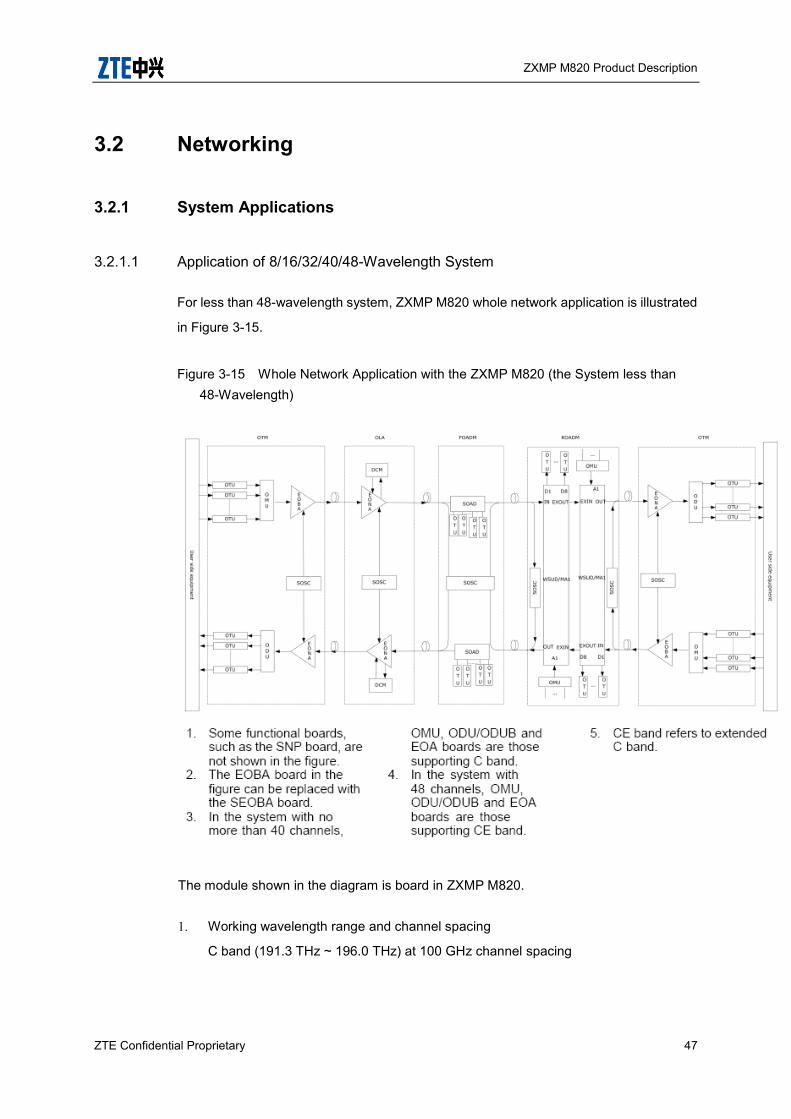
ZXMP M820 Product Description
ZTE Confidential Proprietary 47
3.2 Networking
3.2.1 System Applications
3.2.1.1 Application of 8/16/32/40/48-Wavelength System
For less than 48-wavelength system, ZXMP M820 whole network application is illustrated
in Figure 3-15.
Figure 3-15 Whole Network Application with the ZXMP M820 (the System less than 48-Wavelength)
The module shown in the diagram is board in ZXMP M820.
1. Working wavelength range and channel spacing
C band (191.3 THz ~ 196.0 THz) at 100 GHz channel spacing

ZXMP M820 Product Description
48 ZTE Confidential Proprietary
2. System composition
OTM: Optical terminal equipment. As shown in Figure 3-15. OTU belongs to
the optical transfer platform, OMU and ODU belong to the OM and OD platform,
EOBA and EOPA belong to the optical amplifying platform, SOSC belongs to the
monitoring platform. At the receiving end of the OTM, modules should be added for
dispersion compensation after long distance transmission. The wavelength spacing
transferred by OTU is 100 GHz.
OLA: Optical line amplifier, including EOLA and SOSC. As shown in Figure
3-15, EOLA belongs to the optical amplifying platform; SOSC belongs to the
monitoring platform.
OADM: Optical add/drop multiplexer. As shown in Figure 3-15, OAD belongs to
the add/drop platform, OTU belongs to the optical transfer platform, and SOSC
belongs to the monitoring platform.
3.2.1.2 Application of 80/96-Wavelength System
Take a unidirectional 2-segment transmission for example, and the whole network
application of the 80/96-wavelength ZXMP M820 is illustrated in Figure 3-16.

ZXMP M820 Product Description
ZTE Confidential Proprietary 49
Figure 3-16 Whole Network Application with the ZXMP M820 (the System with 80/96-Wavelength)
The module shown in the diagram is board in ZXMP M820.
1. Working wavelength range and channel spacing
C band at 50 GHz spacing
2. System composition
OTM: Optical terminal equipment
OTU: belongs to the optical transfer platform in Figure 3-16.
OMU, ODU and OCI: The OM and OD platforms in Figure 3-16
OMU/ODU: Multiplex/de-multiplex C band (191.3 THz ~ 196.0 THz), C+ band
(191.35 THz ~ 196.05 THz), with the channel spacing of 100 GHz.
OCI: By adopting the inter-leaver technology, it multiplexes/de-multiplexes C band
and C+ band, and integrates them into the C band multiplexing signals with 50 GHz
channel spacing.
EOBA, EOPA: Belong to the optical amplifying platform in Figure 3-16. In an
80/96-wavelength system, they amplify the C band signals. At the receiving end of
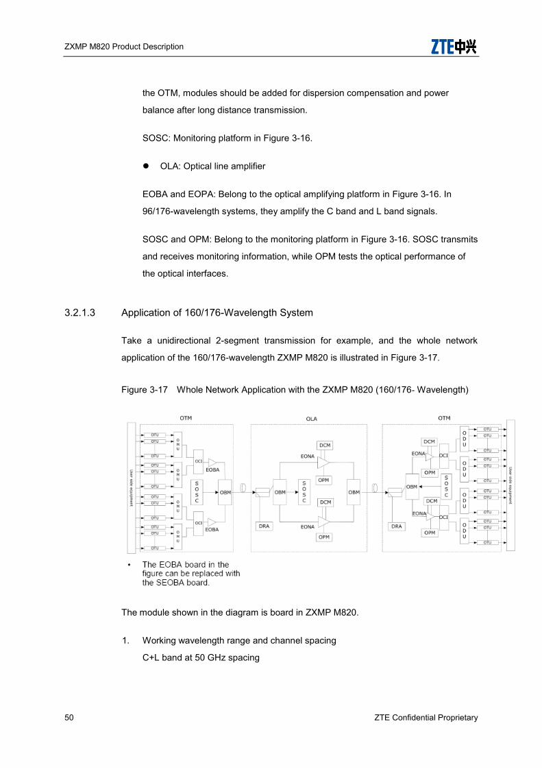
ZXMP M820 Product Description
50 ZTE Confidential Proprietary
the OTM, modules should be added for dispersion compensation and power
balance after long distance transmission.
SOSC: Monitoring platform in Figure 3-16.
OLA: Optical line amplifier
EOBA and EOPA: Belong to the optical amplifying platform in Figure 3-16. In
96/176-wavelength systems, they amplify the C band and L band signals.
SOSC and OPM: Belong to the monitoring platform in Figure 3-16. SOSC transmits
and receives monitoring information, while OPM tests the optical performance of
the optical interfaces.
3.2.1.3 Application of 160/176-Wavelength System
Take a unidirectional 2-segment transmission for example, and the whole network
application of the 160/176-wavelength ZXMP M820 is illustrated in Figure 3-17.
Figure 3-17 Whole Network Application with the ZXMP M820 (160/176- Wavelength)
The module shown in the diagram is board in ZXMP M820.
1. Working wavelength range and channel spacing
C+L band at 50 GHz spacing

ZXMP M820 Product Description
ZTE Confidential Proprietary 51
2. System composition
OTM: Optical terminal equipment
OTU: belongs to the optical transfer platform in Figure 3-17.
OMU, ODU, OCI and OBM: The OM and OD platform in Figure 3-17
OMU/ODU: Multiplex/de-multiplex C band (191.3 THz ~ 196.0 THz), C+ band
(191.35 THz ~ 196.05 THz), L band (187.0 THz ~ 190.9 THz) and L+ band (186.95
THz ~ 190.85 THz) with the channel spacing of100 GHz.
OCI: By adopting the inter-leaver technology, it multiplexes/de-multiplexes C band
and C+ band, L band and L+ band, and integrates them into the C band and L band
multiplexing signals with 50 GHz channel spacing.
OBM: At the transmitting end, the OBM feeds the amplified C/L band signals via the
C/L pass band OM into the fiber. At the receiving end, it de-multiplexes the received
signals into the C/L band multiplexing signals and sends them to the relevant
amplifiers.
EOBA and EOPA: Optical amplifying platform in 0. In 160/176-wavelength system,
they amplify the C band and L band signals. At the receiving end of the OTM,
modules should be added for dispersion compensation and power balance after
long distance transmission.
SOSC: Monitoring platform in Figure 3-17.
OLA: Optical line amplifier. Compared with the 40/48-wavelength system, an OM
part is added for C/L band signals.
OBM: Multiplexes/de-multiplexes signals of C/L band to the C band and L band.
EOBA, DCM and EOPA: Optical amplifying platform in Figure 3-17. In
160/176-wavelength system, they amplify the C band and L band signals. Among them,
DCM compensates dispersion for long distance transmission.
SOSC and OPM: Monitoring platform in Figure 3-17. SOSC transmits and receives
monitoring information, while OPM tests the optical performance of the optical interfaces.
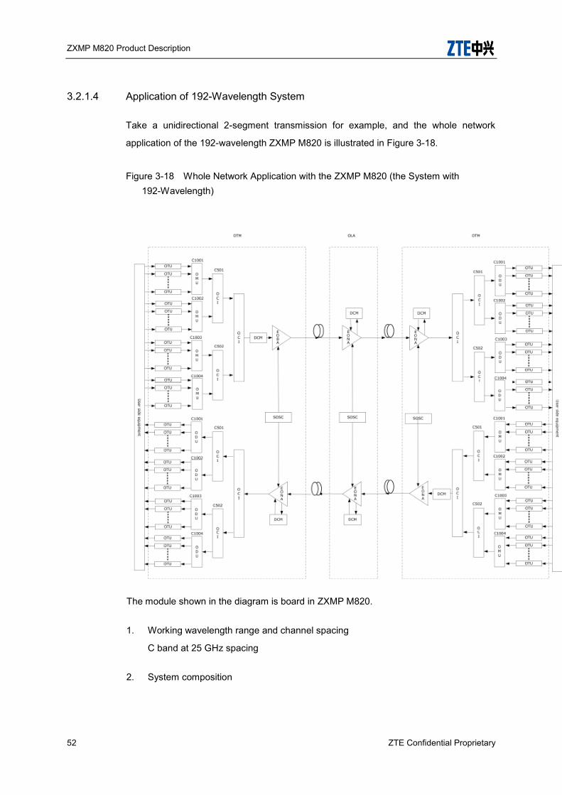
ZXMP M820 Product Description
52 ZTE Confidential Proprietary
3.2.1.4 Application of 192-Wavelength System
Take a unidirectional 2-segment transmission for example, and the whole network
application of the 192-wavelength ZXMP M820 is illustrated in Figure 3-18.
Figure 3-18 Whole Network Application with the ZXMP M820 (the System with 192-Wavelength)
The module shown in the diagram is board in ZXMP M820.
1. Working wavelength range and channel spacing
C band at 25 GHz spacing
2. System composition
ZXMP M820 Product Description
ZTE Confidential Proprietary 53
OTM: Optical terminal equipment
OTU: belongs to the optical transfer platform in Figure 3-18.
OMU, ODU, OCI: The OM and OD platform in Figure 3-18.
OMU/ODU: Multiplex/de-multiplex C1001 sub-band (191.300 THz ~ 196.000 THz),
C1002 sub-band (191.350 THz ~ 196.050 THz), C1003 sub-band (191.325 THz ~
196.025 THz) and C1003 sub-band (191.375 THz ~ 196.075 THz) with the channel
spacing of100 GHz.
OCI:
OCI1 and OCI2, by adopting the inter-leaver technology, it
multiplexes/de-multiplexes C1001 sub-band and C1002 sub-band, C1003sub-band
and C1004 sub-band integrates them into the C band multiplexing signals with 50
GHz channel spacing.
OCI3, by adopting the inter-leaver technology, it multiplexes/de-multiplexes C501
and C502 sub-band integrates them into the C band multiplexing signals with 25
GHz channel spacing
EOBA and EOPA: Optical amplifying platform in 0. In 192-wavelength system, they
amplify the C band signals. At the receiving end of the OTM, modules should be
added for dispersion compensation and power balance after long distance
transmission.
SOSC: Monitoring platform in 0.
SOSC and OPM: Monitoring platform in 0. SOSC transmits and receives monitoring
information, while OPM tests the optical performance of the optical interfaces.
3.2.2 Networking Modes
To satisfy the need of various networking modes and functions, ZXMP M820 can be
configured as an OTM, OADM and OLA.

ZXMP M820 Product Description
54 ZTE Confidential Proprietary
3.2.2.1 Point-to-Point Networking
For short-haul transmission, ZXMP M820 can provide point-to-point network without
OLA, as shown in Figure 3-19.
Figure 3-19 Point-to-Point Networking (Short-Haul)
For long-haul distance, trunk amplification mode is employed. An EOLA is added
between OTMs, as shown in Figure 3-20, which consists of three optical amplifying
segments.
Figure 3-20 Point-to-Point Networking (Long-Haul)
3.2.2.2 Chain Networking
The chain networking application with the OADM function is shown in Figure 3-21.
Figure 3-21 Application of Chain Networking
3.2.2.3 Ring Networking
The ring networking application is shown in Figure 3-22
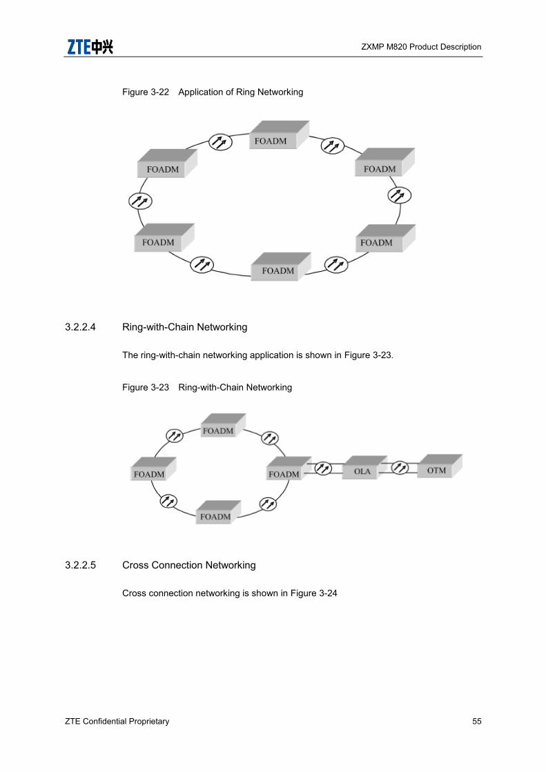
ZXMP M820 Product Description
ZTE Confidential Proprietary 55
Figure 3-22 Application of Ring Networking
3.2.2.4 Ring-with-Chain Networking
The ring-with-chain networking application is shown in Figure 3-23.
Figure 3-23 Ring-with-Chain Networking
3.2.2.5 Cross Connection Networking
Cross connection networking is shown in Figure 3-24

ZXMP M820 Product Description
56 ZTE Confidential Proprietary
Figure 3-24 Cross Connection Networking
3.3 Transmission Codes Supported
By adopting the ultra-long-haul distance optical source and optical amplifying
technologies, the transmission codes supported by ZXMP M820 are listed in the
following tables.
Table 3-5 Transmission Codes Supported by 40 2.5Gbit/s System (G.652&G.655)
Category Specifications Target Distance (km)
Without FEC
(OSNR > 20 dB)
1 36 dB 1 144 km
2 33 dB 2 132 km
3 31dB 3 124 km
10 23 dB 10 92 km
FEC without RAMAN
(OSNR>15dB)
1 41 dB 1×164km
2 38 dB 2×152km

ZXMP M820 Product Description
ZTE Confidential Proprietary 57
Category Specifications Target Distance (km)
3 36dB 3×144km
20 25dB 20×100km
FEC+ RAMAN
(OSNR >15 dB)
1 45dB 1×180km
2 42dB 2×168km
3 40dB 3×160km
20 28 dB 20×112km
Table 3-6 Transmission Codes Supported by 40 /48 10Gbit/s System (G.652&G.655)
Category Specifications Target Distance (km) remark
AFEC NRZ
1 61 dB 1 244km RPOA,40 10Gbit/s
1 49 dB 1 196km DRA, 40 10Gbit/s
1 57 dB 1228km RPOA,48 10Gbit/s
1 48 dB 1 192 km DRA, 4810Gbit/s
30 22 dB 30 88 km -
12 30 dB 12 120 km -
AFEC RZ
1 64 dB 1 256km RPOA,40 10Gbit/s
1 52 dB 1 208km DRA, 40 10Gbit/s
1 60 dB 1240km RPOA,48 10Gbit/s
1 51 dB 1 204 km DRA, 48 10Gbit/s
50 22 dB 50 88 km -
18 30 dB 18 120 km -
Table 3-7 Transmission Codes Supported by 80/96 10Gbit/s System (G.652&G.655)
Category Specifications Target Distance (km) remark
AFEC NRZ
1 45 dB 1 180km DRA, 80 10Gbit/s
1 44 dB 1 176km DRA, 9610Gbit/s
20 22 dB 20 88 km -
8 30 dB 8 120 km -
AFEC RZ 1 48 dB 1 192km DRA, 80 10Gbit/s
1 47 dB 1 188km DRA, 96 10Gbit/s
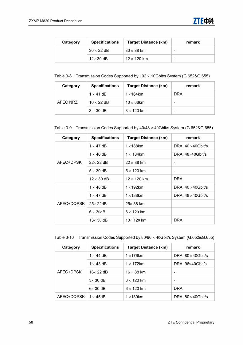
ZXMP M820 Product Description
58 ZTE Confidential Proprietary
Category Specifications Target Distance (km) remark
30 22 dB 30 88 km -
12 30 dB 12 120 km -
Table 3-8 Transmission Codes Supported by 192 10Gbit/s System (G.652&G.655)
Category Specifications Target Distance (km) remark
AFEC NRZ
1 41 dB 1 164km DRA
10 22 dB 10 88km -
3 30 dB 3 120 km -
Table 3-9 Transmission Codes Supported by 40/48 40Gbit/s System (G.652&G.655)
Category Specifications Target Distance (km) remark
AFEC+DPSK
1 47 dB 1 188km DRA, 40 40Gbit/s
1 46 dB 1 184km DRA, 4840Gbit/s
22 22 dB 22 88 km -
5 30 dB 5 120 km -
12 30 dB 12 120 km DRA
AFEC+DQPSK
1 48 dB 1 192km DRA, 40 40Gbit/s
1 47 dB 1 188km DRA, 48 40Gbit/s
25 22dB 25 88 km
6 30dB 6 120 km
13 30 dB 13 120 km DRA
Table 3-10 Transmission Codes Supported by 80/96 40Gbit/s System (G.652&G.655)
Category Specifications Target Distance (km) remark
AFEC+DPSK
1 44 dB 1 176km DRA, 80 40Gbit/s
1 43 dB 1 172km DRA, 9640Gbit/s
16 22 dB 16 88 km -
3 30 dB 3 120 km -
6 30 dB 6 120 km DRA
AFEC+DQPSK 1 45dB 1 180km DRA, 80 40Gbit/s

ZXMP M820 Product Description
ZTE Confidential Proprietary 59
Category Specifications Target Distance (km) remark
1 44 dB 1 176km DRA, 96 40Gbit/s
18 22 dB 18 88 km
4 30 dB 4 120km
7 30 dB 7 120 km DRA
Table 3-11 Transmission Codes Supported by 80 100Gbit/s System (G.652 with DCM)
Category Specifications Target Distance (km) remark
SD+FEC+PM-QPSK
1x45dB 1x180km DRA, 80x100Gbit/s
16x22 dB 16x88 km
4x30 dB 4x120km
7x30 dB 7x120 km DRA
Table 3-12 Transmission Codes Supported by 80 100Gbit/s System (G.652 without DCM)
Category Specifications Target Distance (km) remark
SD+FEC+PM-QPSK
1x45dB 1x180km DRA, 80x100Gbit/s
20x22 dB 20x88 km
4x30 dB 4x120km
7x30 dB 7x120 km DRA
Table 3-13 Transmission Codes Supported by 80 100Gbit/s System (G.655 with DCM)
Category Specifications Target Distance (km) remark
SD+FEC+PM-QPSK
1x45dB 1x180km DRA, 80x100Gbit/s
10x22 dB 10x88 km
3x30 dB 3x120km
6x30 dB 6x120 km DRA

ZXMP M820 Product Description
60 ZTE Confidential Proprietary
Table 3-14 Transmission Codes Supported by 80 100Gbit/s System (G.655 without DCM)
Category Specifications Target Distance (km) remark
SD+FEC+PM-QPSK
1x45dB 1x180km DRA, 80x100Gbit/s
12x22 dB 12x88 km
3x30 dB 3x120km
6x30 dB 6x120 km DRA
Note: SD-FEC is soft decision FEC coding and decoding, and means that the channel difference should be
included. Target Distance is calculated at 0.25dB/km.

ZXMP M820 Product Description
ZTE Confidential Proprietary 61
4 System Architecture This chapter briefly introduces the overall structure of ZXMP M820, including hardware
and software, and its applications.
4.1 Description of System Functional Platform
The functional block diagram of ZXMP M820 is shown in Table 4-1
Figure 4-1 Functional Blocks of the ZXMP M820
ZXMP M820 consists of hardware system and NM software system, which are
independent of each other and work coordinately.
ZXMP M820 hardware system consists of optical transfer platform, service convergent
platform, optical wavelength multiplexing (OM) and optical wavelength de-multiplexing
(OD) platforms, add/drop platform, optical amplifying platform and monitoring platform.
4.1.1 Optical transfer platform
It employs Optical/electric/optical conversion mode to convert wavelengths between the
service signals and line signals.
The service signals support the SDH signals at STM-1/4/16/64/256 rates, OC-3/12/48/
192/768 and other service signals (i.e. POS, FC, FICON, ESCON, DVB, FDDI, FE, GE,

ZXMP M820 Product Description
62 ZTE Confidential Proprietary
10GE, 100GE, ATM and PDH) at the client side, satisfying the G.957, G691 and
IEEE802.3 recommendation.
The line signals are compliant with the G.692 recommendation.
4.1.2 Service convergence platform
It converge multiple low-speed signals into one wavelength for transmission, and
completes its reversion process.
The low-speed signals include STM-1, STM-4, STM-16, STM-64, GE, 10GE, 40GE and
100GE.
The maximum rate at the line side is 120Gbit/s.
4.1.3 OM/OD platform
It consists of two parts: the OM and OD.
The OM: It couples and multiplexes multiple optical signals with different wavelengths
from the optical transfer platform and service convergent platform into one fiber for
transmission.
The OD: It separates the line optical signals from the optical amplifying platform by
wavelengths, and sends them to different optical transfer platforms and service
convergent platforms.
The OM and OD of ZXMP M820 employ C band with 100 GHz/50GHz channel spacing
in less than 40-wavelength /80/96-wavelength transmission.
The OM and OD of ZXMP M820 employ C/L band by using interleaver technology with
50 GHz channel spacing in 40-176-wavelength super-large capacity transmission.
The OM and OD of ZXMP M820 employ C band by using interleaver technology with 25
GHz channel spacing in 192-wavelength super-large capacity transmission.

ZXMP M820 Product Description
ZTE Confidential Proprietary 63
4.1.4 Add/drop platform
It implements add/drop and multiplexing function for the wavelength of the optical line
signals. The ZXMP M820 can be configured as a fixed optical add/drop multiplexer
(FOADM) or a reconfigurable optical add/drop multiplexer (ROADM) depending on
whether the wavelengths to be added/dropped are fixed.
4.1.5 Optical amplifying platform
It compensates optical signal power in long distance transmission with optical amplifying
technology. Normally, it is located at the back and in front of the OM/OD platform, as well
as in the middle of the line transmission.
The optical amplifying part of ZXMP M820 employs C band EDFA in less than
40-wavelength/80/96 wavelength transmission.
The optical amplifying platform of ZXMP M820 amplifies the C band and L band
respectively in 40-176-wavelength transmission. The amplifier types involve C band
EDFA, L band EDFA, C+L band RAMAN/EDFA hybrid amplifiers.
4.1.6 Monitoring platform
It collects handles and reports various information such as platform configurations,
alarms and performance to the NMS.
It receives the commands sent by the NMS and transfers them to the target board.
It transmits the NMS information with the specified monitoring optical channel. The
wavelength of the monitoring channel is 1510 nm at 100Mbit/s.
The NM Software System is introduced in chapter 4.3
4.2 Hardware Architecture
4.2.1 Sub-rack
ZXMP M820 has three kinds of sub-racks, NX sub-rack and CX sub-rack and DX

ZXMP M820 Product Description
64 ZTE Confidential Proprietary
sub-rack
NX sub-rack can be installed in 21 inch or 19 inch cabinet. One 21 inch and 2.2 m high
cabinet can install 4 NX-sub-racks or CX sub-racks or DX sub-racks. One 19 inch and
2.2 m high cabinet can install 3 NX-sub-racks.
Figure 4-2 Layout of ZXMP M820 NX Sub-rack (21 inch)
Dust Proof Net
SEIA
Fiber Cable Area
SFANASFANASFANASFANA
SPWA
SPWA
Wiring
Area
SNP
SNP
SOSC
Figure 4-3 Layout of ZXMP M820 NX Sub-rack (19 inch)
Fiber Cable Area
2 4 6 8 14 16 18 20 22 1410 12
SE
IAS
PW
A
SP
WA
Wiring
Area
SFANASFANASFANASFANA
Dust Proof Net
1 3 5 7 13 15 17 19 219 11
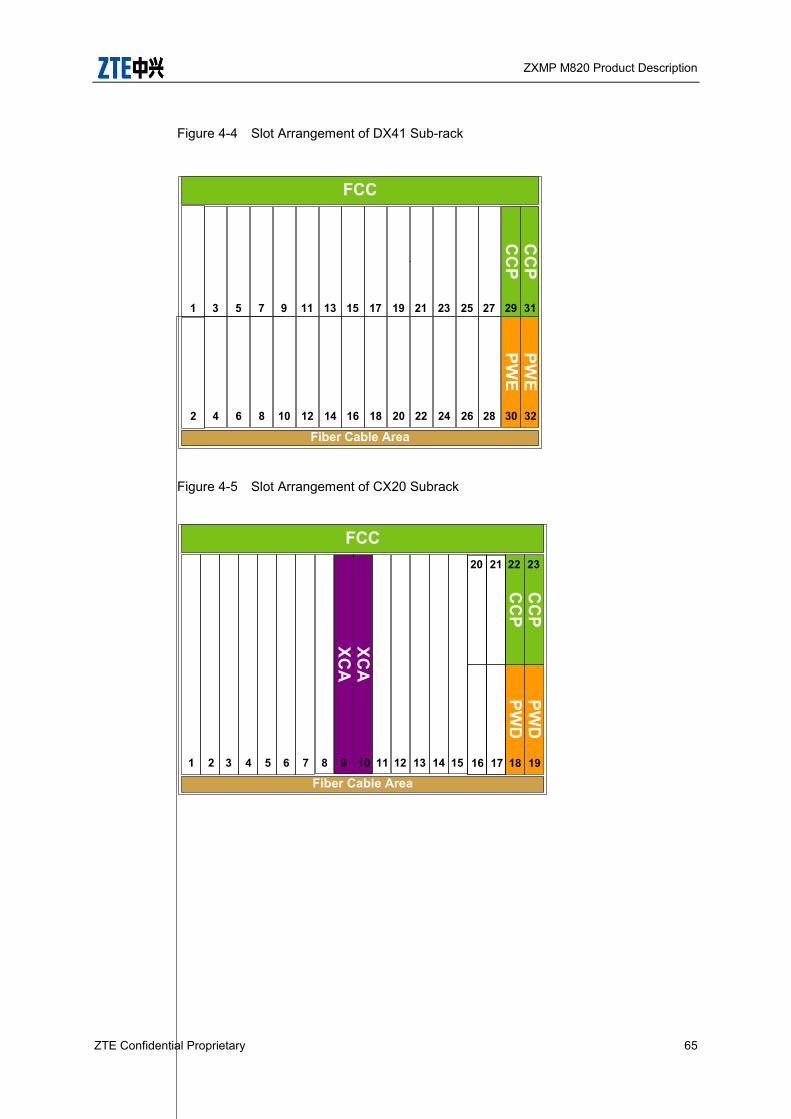
ZXMP M820 Product Description
ZTE Confidential Proprietary 65
Figure 4-4 Slot Arrangement of DX41 Sub-rack
Fiber Cable Area
FCC
PWE
PWE
30 32
CC
PC
CP
1210 161442 86 28262018 2422
29 31119 151331 75 27251917 2321
Figure 4-5 Slot Arrangement of CX20 Subrack
Fiber Cable Area
FCC
XCA
XCA
1 2 3 4 5 6 7 8 9 10 11 12 13 14 15
PWD
PWD
18 19
CC
PC
CP
22 23
16 17
20 21
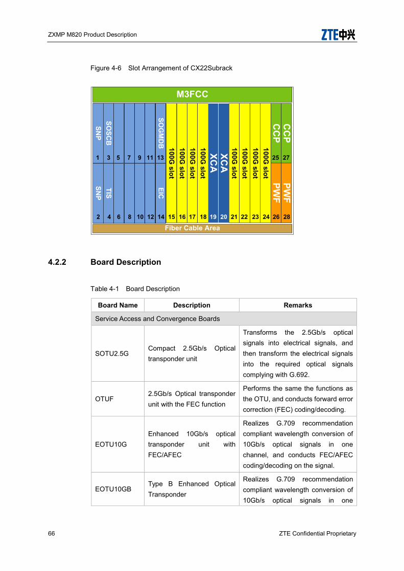
ZXMP M820 Product Description
66 ZTE Confidential Proprietary
Figure 4-6 Slot Arrangement of CX22Subrack
SOG
MD
BEIC
100G slot
Fiber Cable Area
M3FCC
100G slot
100G slot
100G slot
XCA
XCA
100G slot
15 16 17 18 19 20
100G slot
100G slot
21 22
PWF
PWF
26 28
CC
PC
CP
100G slot
23 24
SNP
SNP
SOSC
BTIS
1 3 5 7 25 27
2 4 6 8 12 14
9
10
11 13
4.2.2 Board Description
Table 4-1 Board Description
Board Name Description Remarks
Service Access and Convergence Boards
SOTU2.5G Compact 2.5Gb/s Optical transponder unit
Transforms the 2.5Gb/s optical signals into electrical signals, and then transform the electrical signals into the required optical signals complying with G.692.
OTUF 2.5Gb/s Optical transponder unit with the FEC function
Performs the same the functions as the OTU, and conducts forward error correction (FEC) coding/decoding.
EOTU10G Enhanced 10Gb/s optical transponder unit with FEC/AFEC
Realizes G.709 recommendation compliant wavelength conversion of 10Gb/s optical signals in one channel, and conducts FEC/AFEC coding/decoding on the signal.
EOTU10GB Type B Enhanced Optical Transponder
Realizes G.709 recommendation compliant wavelength conversion of 10Gb/s optical signals in one
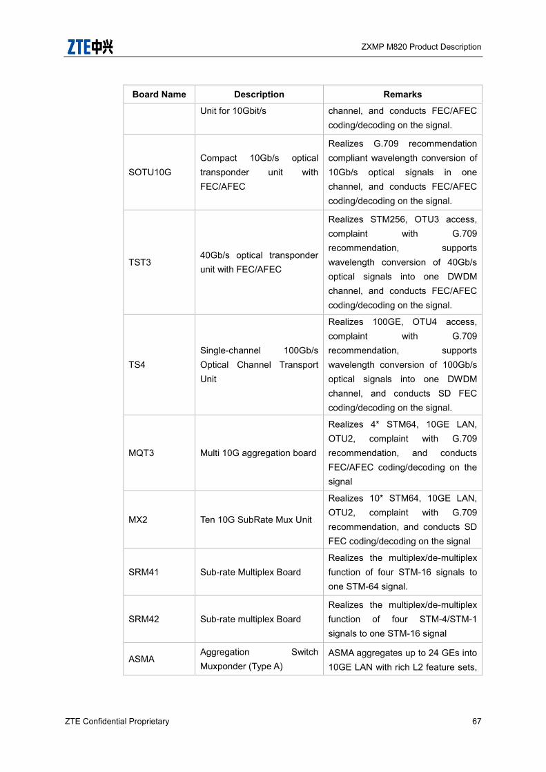
ZXMP M820 Product Description
ZTE Confidential Proprietary 67
Board Name Description Remarks
Unit for 10Gbit/s channel, and conducts FEC/AFEC coding/decoding on the signal.
SOTU10G Compact 10Gb/s optical transponder unit with FEC/AFEC
Realizes G.709 recommendation compliant wavelength conversion of 10Gb/s optical signals in one channel, and conducts FEC/AFEC coding/decoding on the signal.
TST3 40Gb/s optical transponder unit with FEC/AFEC
Realizes STM256, OTU3 access, complaint with G.709 recommendation, supports wavelength conversion of 40Gb/s optical signals into one DWDM channel, and conducts FEC/AFEC coding/decoding on the signal.
TS4 Single-channel 100Gb/s Optical Channel Transport Unit
Realizes 100GE, OTU4 access, complaint with G.709 recommendation, supports wavelength conversion of 100Gb/s optical signals into one DWDM channel, and conducts SD FEC coding/decoding on the signal.
MQT3 Multi 10G aggregation board
Realizes 4* STM64, 10GE LAN, OTU2, complaint with G.709 recommendation, and conducts FEC/AFEC coding/decoding on the signal
MX2 Ten 10G SubRate Mux Unit
Realizes 10* STM64, 10GE LAN, OTU2, complaint with G.709 recommendation, and conducts SD FEC coding/decoding on the signal
SRM41 Sub-rate Multiplex Board Realizes the multiplex/de-multiplex function of four STM-16 signals to one STM-64 signal.
SRM42 Sub-rate multiplex Board Realizes the multiplex/de-multiplex function of four STM-4/STM-1 signals to one STM-16 signal
ASMA Aggregation Switch Muxponder (Type A)
ASMA aggregates up to 24 GEs into 10GE LAN with rich L2 feature sets,
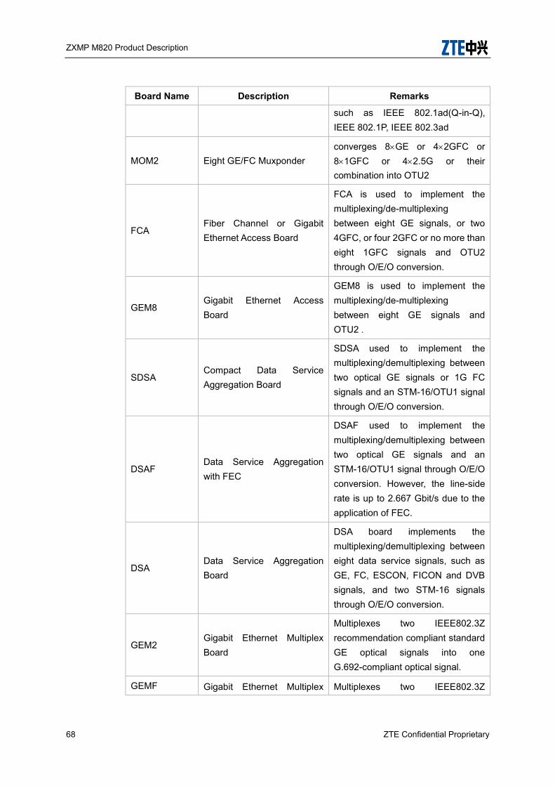
ZXMP M820 Product Description
68 ZTE Confidential Proprietary
Board Name Description Remarks
such as IEEE 802.1ad(Q-in-Q), IEEE 802.1P, IEEE 802.3ad
MOM2 Eight GE/FC Muxponder converges 8GE or 42GFC or 81GFC or 42.5G or their combination into OTU2
FCA Fiber Channel or Gigabit Ethernet Access Board
FCA is used to implement the multiplexing/de-multiplexing between eight GE signals, or two 4GFC, or four 2GFC or no more than eight 1GFC signals and OTU2 through O/E/O conversion.
GEM8 Gigabit Ethernet Access Board
GEM8 is used to implement the multiplexing/de-multiplexing between eight GE signals and OTU2 .
SDSA Compact Data Service Aggregation Board
SDSA used to implement the multiplexing/demultiplexing between two optical GE signals or 1G FC signals and an STM-16/OTU1 signal through O/E/O conversion.
DSAF Data Service Aggregation with FEC
DSAF used to implement the multiplexing/demultiplexing between two optical GE signals and an STM-16/OTU1 signal through O/E/O conversion. However, the line-side rate is up to 2.667 Gbit/s due to the application of FEC.
DSA Data Service Aggregation Board
DSA board implements the multiplexing/demultiplexing between eight data service signals, such as GE, FC, ESCON, FICON and DVB signals, and two STM-16 signals through O/E/O conversion.
GEM2 Gigabit Ethernet Multiplex Board
Multiplexes two IEEE802.3Z recommendation compliant standard GE optical signals into one G.692-compliant optical signal.
GEMF Gigabit Ethernet Multiplex Multiplexes two IEEE802.3Z
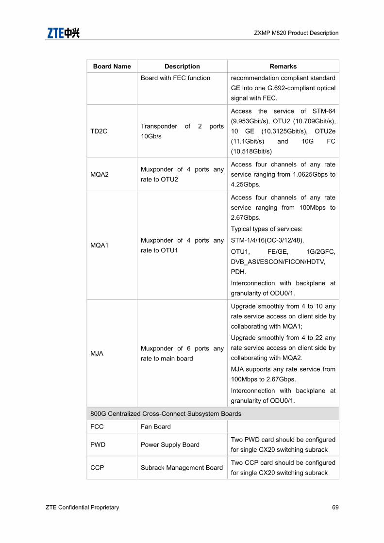
ZXMP M820 Product Description
ZTE Confidential Proprietary 69
Board Name Description Remarks
Board with FEC function recommendation compliant standard GE into one G.692-compliant optical signal with FEC.
TD2C Transponder of 2 ports 10Gb/s
Access the service of STM-64 (9.953Gbit/s), OTU2 (10.709Gbit/s), 10 GE (10.3125Gbit/s), OTU2e (11.1Gbit/s) and 10G FC (10.518Gbit/s)
MQA2 Muxponder of 4 ports any rate to OTU2
Access four channels of any rate service ranging from 1.0625Gbps to 4.25Gbps.
MQA1 Muxponder of 4 ports any rate to OTU1
Access four channels of any rate service ranging from 100Mbps to 2.67Gbps.
Typical types of services:
STM-1/4/16(OC-3/12/48),
OTU1, FE/GE, 1G/2GFC, DVB_ASI/ESCON/FICON/HDTV, PDH.
Interconnection with backplane at granularity of ODU0/1.
MJA Muxponder of 6 ports any rate to main board
Upgrade smoothly from 4 to 10 any rate service access on client side by collaborating with MQA1;
Upgrade smoothly from 4 to 22 any rate service access on client side by collaborating with MQA2.
MJA supports any rate service from 100Mbps to 2.67Gbps.
Interconnection with backplane at granularity of ODU0/1.
800G Centralized Cross-Connect Subsystem Boards
FCC Fan Board
PWD Power Supply Board Two PWD card should be configured for single CX20 switching subrack
CCP Subrack Management Board Two CCP card should be configured for single CX20 switching subrack
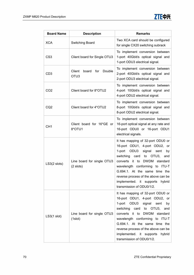
ZXMP M820 Product Description
70 ZTE Confidential Proprietary
Board Name Description Remarks
XCA Switching Board Two XCA card should be configured for single CX20 switching subrack
CS3 Client board for Single OTU3 To implement conversion between 1-port 40Gbit/s optical signal and 1-port ODU3 electrical signal.
CD3 Client board for Double OTU3
To implement conversion between 2-port 40Gbit/s optical signal and 2-port ODU3 electrical signal.
CO2 Client board for 8*OTU2 To implement conversion between 4-port 10Gbit/s optical signal and 4-port ODU2 electrical signal.
CQ2 Client board for 4*OTU2 To implement conversion between 8-port 10Gbit/s optical signal and 8-port ODU2 electrical signal.
CH1 Client board for 16*GE or 8*OTU1
To implement conversion between 16-port optical signal at any rate and 16-port ODU0 or 16-port ODU1 electrical signals.
LS3(2 slots) Line board for single OTU3 (2 slots)
It has mapping of 32-port ODU0 or 16-port ODU1, 4-port ODU2, or 1-port ODU3 signal sent by switching card to OTU3, and converts it to DWDM standard wavelength conforming to ITU-T G.694.1. At the same time the reverse process of the above can be implemented. it supports hybrid transmission of ODU0/1/2.
LS3(1 slot) Line board for single OTU3 (1slot)
It has mapping of 32-port ODU0 or 16-port ODU1, 4-port ODU2, or 1-port ODU3 signal sent by switching card to OTU3, and converts it to DWDM standard wavelength conforming to ITU-T G.694.1. At the same time the reverse process of the above can be implemented. it supports hybrid transmission of ODU0/1/2.

ZXMP M820 Product Description
ZTE Confidential Proprietary 71
Board Name Description Remarks
LO2 Line board for 8*OTU2
It has mapping of 64-port ODU0 or 32-port ODU1, 8-port ODU2 signal sent by switching card to OTU2, and converts it to DWDM standard wavelength conforming to ITU-T G.694.1. At the same time the reverse process of the above can be implemented. it supports hybrid transmission of ODU0/1.
LO2B Line board for 8*OTU2 with PIC technique
It has mapping of 64-port ODU0 or 32-port ODU1, 8-port ODU2 signal sent by switching card to OTU2, and converts it to DWDM standard wavelength conforming to ITU-T G.694.1. At the same time the reverse process of the above can be implemented. it supports hybrid transmission of ODU0/1.
LQ2 Line board for 4*OTU2
It has mapping of 32-port ODU0 or 16-port ODU1, 4-port ODU2 signal sent by switching card to OTU2, and converts it to DWDM standard wavelength conforming to ITU-T G.694.1. At the same time the reverse process of the above can be implemented. it supports hybrid transmission of ODU0/1.
LD2B Line board for 2*OTU2
It has mapping of 16-port ODU0 or 8-port ODU1, 2-port ODU2 signal sent by switching card to OTU2, and converts it to DWDM standard wavelength conforming to ITU-T G.694.1. At the same time the reverse process of the above can be implemented. it supports hybrid transmission of ODU0/1.
Optical Amplification Subsystem Boards
EOBA Enhanced Optical booster It is equipped with the erbium-doped fiber amplifier (EDFA) to boost

ZXMP M820 Product Description
72 ZTE Confidential Proprietary
Board Name Description Remarks
amplifier optical power of signals. It is usually used at the transmitting end.
EOLA Enhanced Optical line amplifier
It is equipped with the erbium-doped fiber amplifier (EDFA) to amplify optical signals. It is usually used at the optical relay segment.
EOPA Enhanced Optical pre-amplifier
It is equipped with the erbium-doped fiber amplifier (EDFA) to pre-amplify optical signals. It is usually used at the receiving end.
SEOBA Compact Enhanced Optical booster amplifier
It is equipped with the erbium-doped fiber amplifier (EDFA) to boost optical power of signals. It is usually used at the transmitting end.
SEOLA Compact Enhanced Optical line amplifier
It is equipped with the erbium-doped fiber amplifier (EDFA) to amplify optical signals. It is usually used at the optical relay segment.
SEOPA Compact Enhanced Optical pre-amplifier
It is equipped with the erbium-doped fiber amplifier (EDFA) to pre-amplify optical signals. It is usually used at the receiving end.
EONA Enhanced node amplifier
It is equipped with erbium-doped fiber amplifier (EDFA) to amplify optical signals. The gain range can be adjusted greatly to meet the requirements of different regeneration distances. DCM module can be inserted in the middle for the dispersion compensation. It is usually Configured in the middle of an Optical Multiplex Section.
EONAH High power enhanced node amplifier
It is equipped with erbium-doped fiber amplifier (EDFA) to amplify optical signals and offer high output power. The gain range can be adjusted greatly to meet the requirements of different
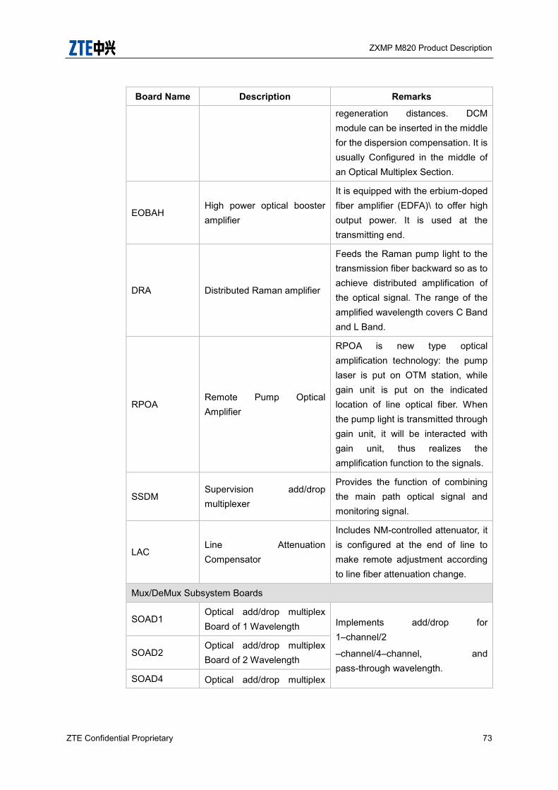
ZXMP M820 Product Description
ZTE Confidential Proprietary 73
Board Name Description Remarks
regeneration distances. DCM module can be inserted in the middle for the dispersion compensation. It is usually Configured in the middle of an Optical Multiplex Section.
EOBAH High power optical booster amplifier
It is equipped with the erbium-doped fiber amplifier (EDFA)\ to offer high output power. It is used at the transmitting end.
DRA Distributed Raman amplifier
Feeds the Raman pump light to the transmission fiber backward so as to achieve distributed amplification of the optical signal. The range of the amplified wavelength covers C Band and L Band.
RPOA Remote Pump Optical Amplifier
RPOA is new type optical amplification technology: the pump laser is put on OTM station, while gain unit is put on the indicated location of line optical fiber. When the pump light is transmitted through gain unit, it will be interacted with gain unit, thus realizes the amplification function to the signals.
SSDM Supervision add/drop multiplexer
Provides the function of combining the main path optical signal and monitoring signal.
LAC Line Attenuation Compensator
Includes NM-controlled attenuator, it is configured at the end of line to make remote adjustment according to line fiber attenuation change.
Mux/DeMux Subsystem Boards
SOAD1 Optical add/drop multiplex Board of 1 Wavelength Implements add/drop for
1–channel/2
–channel/4–channel, and pass-through wavelength.
SOAD2 Optical add/drop multiplex Board of 2 Wavelength
SOAD4 Optical add/drop multiplex

ZXMP M820 Product Description
74 ZTE Confidential Proprietary
Board Name Description Remarks
board of 4 Wavelength
SOGMD Compact Optical Group Mux/DeMux Board
Multiplexes/de-multiplexes four group of wavelengths through red-blue ribbon filters.
OMU Optical multiplex unit
Multiplex optical signals with different wavelengths to one fiber, and provides 8-wave, 16-wave, 32-wave, 40-wave, 48-wave and 80-wave multiplexers.
ODU Optical de-multiplex unit
Separates optical signals of different channels in one fiber from each other, and provides 8-wave, 16-wave, 32-wave, 40-wave, 48-wave and 80-wave de-multiplexers.
VMUX Variable attenuation MUX
Multiplex unit with channel power pre-balance. With AWG+VOA technique, it adjusts attenuations of channels, and then multiplexes them into one channel for output via voltage or current control. Configured at OTM site, it can independently adjust optical power of each channel for channel power pre-balance.
VMUXB
Variable Insertion Loss Multiplexer (B
Type)
Multiplexes signals of 40 optical channels in C band, and implements the channel power pre-equalization.
ODUB Optical De-Multiplexing Unit (B Type)
De-multiplexes signals of 40 optical channels, and provides online monitoring interface of multiplexed optical signal.
OCI Optical channel multiplex /de-multiplex inter-leaver board
Completes the multiplex/de-multiplex of the C band or L band channel interleave at the same time, applying in 80-wave system.
OBM Broadband multiplex board Multiplexes/de-multiplexes the C/L
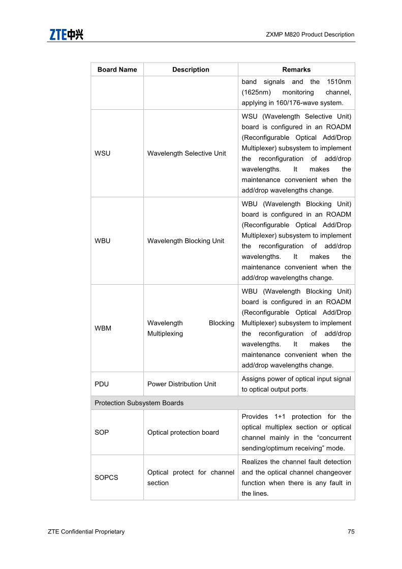
ZXMP M820 Product Description
ZTE Confidential Proprietary 75
Board Name Description Remarks
band signals and the 1510nm (1625nm) monitoring channel, applying in 160/176-wave system.
WSU Wavelength Selective Unit
WSU (Wavelength Selective Unit) board is configured in an ROADM (Reconfigurable Optical Add/Drop Multiplexer) subsystem to implement the reconfiguration of add/drop wavelengths. It makes the maintenance convenient when the add/drop wavelengths change.
WBU Wavelength Blocking Unit
WBU (Wavelength Blocking Unit) board is configured in an ROADM (Reconfigurable Optical Add/Drop Multiplexer) subsystem to implement the reconfiguration of add/drop wavelengths. It makes the maintenance convenient when the add/drop wavelengths change.
WBM Wavelength Blocking Multiplexing
WBU (Wavelength Blocking Unit) board is configured in an ROADM (Reconfigurable Optical Add/Drop Multiplexer) subsystem to implement the reconfiguration of add/drop wavelengths. It makes the maintenance convenient when the add/drop wavelengths change.
PDU Power Distribution Unit Assigns power of optical input signal to optical output ports.
Protection Subsystem Boards
SOP Optical protection board
Provides 1+1 protection for the optical multiplex section or optical channel mainly in the “concurrent sending/optimum receiving” mode.
SOPCS Optical protect for channel section
Realizes the channel fault detection and the optical channel changeover function when there is any fault in the lines.

ZXMP M820 Product Description
76 ZTE Confidential Proprietary
Board Name Description Remarks
SOPMS Optical protect for Mux section
Mainly serves to implement the changeover function of the optical multiplex section shared protection.
OMCP Optical Protect for Mux Section
Performs service add/drop and protection switching by means of optical signal cross-connect. The optical switching module in OMCP board implements the function of OMCP board.
Optical Layer Management Subsystem Boards
OPM Optical performance monitoring board
Provides optical performance monitoring function for each optical channel with measuring parameters including optical power, central wavelength and optical S/N ratio and reports the corresponding data to the NMS.
EOPM Enhanced Optical Channel Performance Monitor
Monitors optical channel wavelength, optical power and OSNR of 4-channel or 8-channel WDM optical signals. Measures parameters of each optical channel, including optical power, central wavelength and OSNR. Reports measured data to NMS.
OWM Optical Wavelength Monitor
OWM could automatic detect the abnormal wavelength shift of the OTU, and send adjustment command to the aim OTU until the wavelength shift is in the normal range.
EOWM Enhanced Optical Wavelength Monitor Board
Monitors the central frequency wander of optical channels after the multiplexing and reports the frequency adjustment information to the SNP board.
DCU Dispersion Compensation
Board Used for dispersion compensation of 40G NRZ-DPSK, RZ-DQPSK or
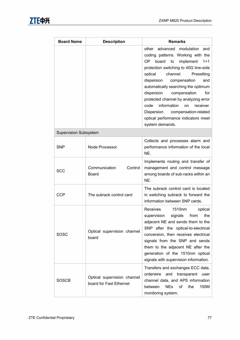
ZXMP M820 Product Description
ZTE Confidential Proprietary 77
Board Name Description Remarks
other advanced modulation and coding patterns. Working with the OP board to implement 1+1 protection switching to 40G line-side optical channel. Presetting dispersion compensation and automatically searching the optimum dispersion compensation for protected channel by analyzing error code information on receiver. Dispersion compensation-related optical performance indicators meet system demands.
Supervision Subsystem
SNP Node Processor Collects and processes alarm and performance information of the local NE.
SCC Communication Control Board
Implements routing and transfer of management and control message among boards of sub-racks within an NE.
CCP The subrack control card The subrack control card is located in switching subrack to forward the information between SNP cards.
SOSC Optical supervision channel board
Receives 1510nm optical supervision signals from the adjacent NE and sends them to the SNP after the optical-to-electrical conversion, then receives electrical signals from the SNP and sends them to the adjacent NE after the generation of the 1510nm optical signals with supervision information.
SOSCB Optical supervision channel board for Fast Ethernet
Transfers and exchanges ECC data, orderwire and transparent user channel data, and APS information between NEs of the 100M monitoring system.
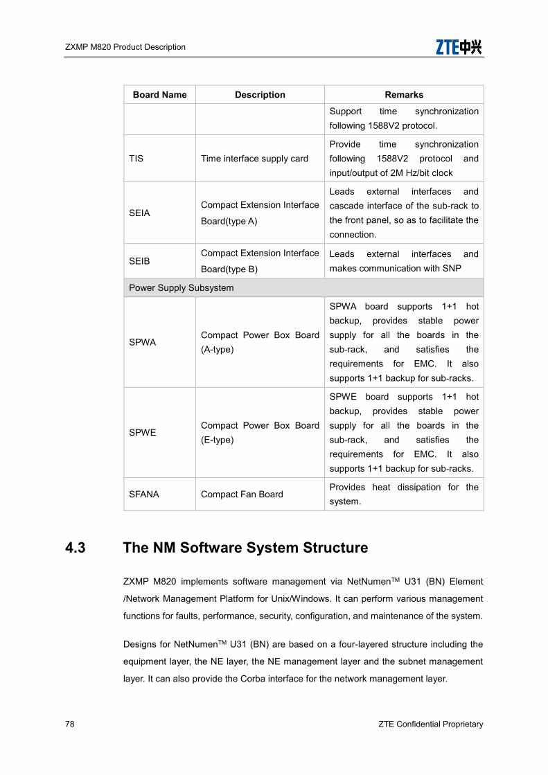
ZXMP M820 Product Description
78 ZTE Confidential Proprietary
Board Name Description Remarks
Support time synchronization following 1588V2 protocol.
TIS Time interface supply card Provide time synchronization following 1588V2 protocol and input/output of 2M Hz/bit clock
SEIA Compact Extension Interface
Board(type A)
Leads external interfaces and cascade interface of the sub-rack to the front panel, so as to facilitate the connection.
SEIB Compact Extension Interface
Board(type B) Leads external interfaces and makes communication with SNP
Power Supply Subsystem
SPWA Compact Power Box Board (A-type)
SPWA board supports 1+1 hot backup, provides stable power supply for all the boards in the sub-rack, and satisfies the requirements for EMC. It also supports 1+1 backup for sub-racks.
SPWE Compact Power Box Board (E-type)
SPWE board supports 1+1 hot backup, provides stable power supply for all the boards in the sub-rack, and satisfies the requirements for EMC. It also supports 1+1 backup for sub-racks.
SFANA Compact Fan Board Provides heat dissipation for the system.
4.3 The NM Software System Structure
ZXMP M820 implements software management via NetNumenTM U31 (BN) Element
/Network Management Platform for Unix/Windows. It can perform various management
functions for faults, performance, security, configuration, and maintenance of the system.
Designs for NetNumenTM U31 (BN) are based on a four-layered structure including the
equipment layer, the NE layer, the NE management layer and the subnet management
layer. It can also provide the Corba interface for the network management layer.
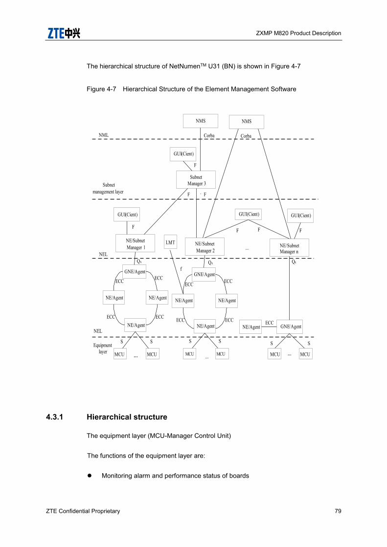
ZXMP M820 Product Description
ZTE Confidential Proprietary 79
The hierarchical structure of NetNumenTM U31 (BN) is shown in Figure 4-7
Figure 4-7 Hierarchical Structure of the Element Management Software
4.3.1 Hierarchical structure
The equipment layer (MCU-Manager Control Unit)
The functions of the equipment layer are:
Monitoring alarm and performance status of boards
GUI(Cient) GUI(Cient)
NE/SubnetManager 2
NE/SubnetManager n
GNE/Agent
NE/AgentNE/Agent
NE/AgentECC
ECCECC
ECC ECC
SS
NE/Agent GNE/Agent
S S
FF
LMT
fQx
NML
NEL
NEL
Equipment layer
Qx
Corba
Subnet management layer
SubnetManager 3
GUI(Cient)
F
NMS
F
Corba
NE/SubnetManager 1
GNE/Agent
NE/AgentNE/Agent
NE/Agent
MCU MCU
ECC
ECCECC
ECC
SS
F
Qx
GUI(Cient)
F
F
MCU MCU MCUMCU
NMS
…..… ...
...
…

ZXMP M820 Product Description
80 ZTE Confidential Proprietary
Receiving EMS commands
Controlling boards to implement certain operations
The NE layer, which is the Agent in the EMS
The functions of the NE layer are:
Managing each NE
Configuring each board when NE is powered on for initialization
Monitoring alarm and performance status of whole NEs under normal running
conditions
Receiving and processing the monitoring commands of NE manager layer through
gateway NE (GNE)
The NE management layer (Manager): controls and coordinates a series of NEs,
including Manager, graphical user interface (GUI) and Local Maintenance Terminal
(LMT).
The functions of the NE management layer are:
The core of the NE manager layer is the Manager (or Server), which can manage
multiple subnets, control and coordinate NE equipment.
GUI provides graphic user interfaces and converts the requirements of user
management into the commands of the internal formats and sends them down to
the Manager.
LMT simply combines GUI and Manager via controlling user rights and software
functional parts, provides some of NE management functions for local NEs
commissioning and maintenance.
The subnet management layer: its structure is similar to that of NE management layer,
and the NEs configuration and maintenance commands are indirectly performed through
NE management layer.
The subnet management system sends a command to the NE management system, via
ZXMP M820 Product Description
ZTE Confidential Proprietary 81
which forwards it to the NE. After then, the NE responds to the subnet management
system through the NE management system. In addition, it can provide the network
management layer with the Corba interface.
4.3.2 Interface description
Qx interface:
As shown in Figure 4-7, t is the interface between the Agent and the Manager, i.e.,
the interface between the SNP board and the computer where the Manager
program resides. It complies with the TCP/IP.
F interface:
As shown in Figure 4-7, t is the interface between the GUI and the Manager, i.e., the
interface between the GUI and the computer where the Manager program resides. It
complies with the TCP/IP.
f interface:
As shown in Figure 4-7, t is the interface between the Agent and LMT, i.e. the
interface between the SNP board and the local maintenance terminal. On the local
maintenance terminal, related NM software is installed. This interface complies with
the TCP/IP.
S interface:
As shown in Figure 4-7, t is the interface between Agent and MCU, i.e., the
communication interface between the SNP board and other boards. S interface
adopts the point-to-multi-point communication mode based on the HDLC
communication mechanism.
ECC interface:
As shown in Figure 4-7, t is the interface between Agents, i.e. the communication
interface between NEs. It uses DCC for communication, supports customized
communication protocol and standard protocol at the same time, and implements
bridge function on Agent.
Please refer to the element management manuals for more details.
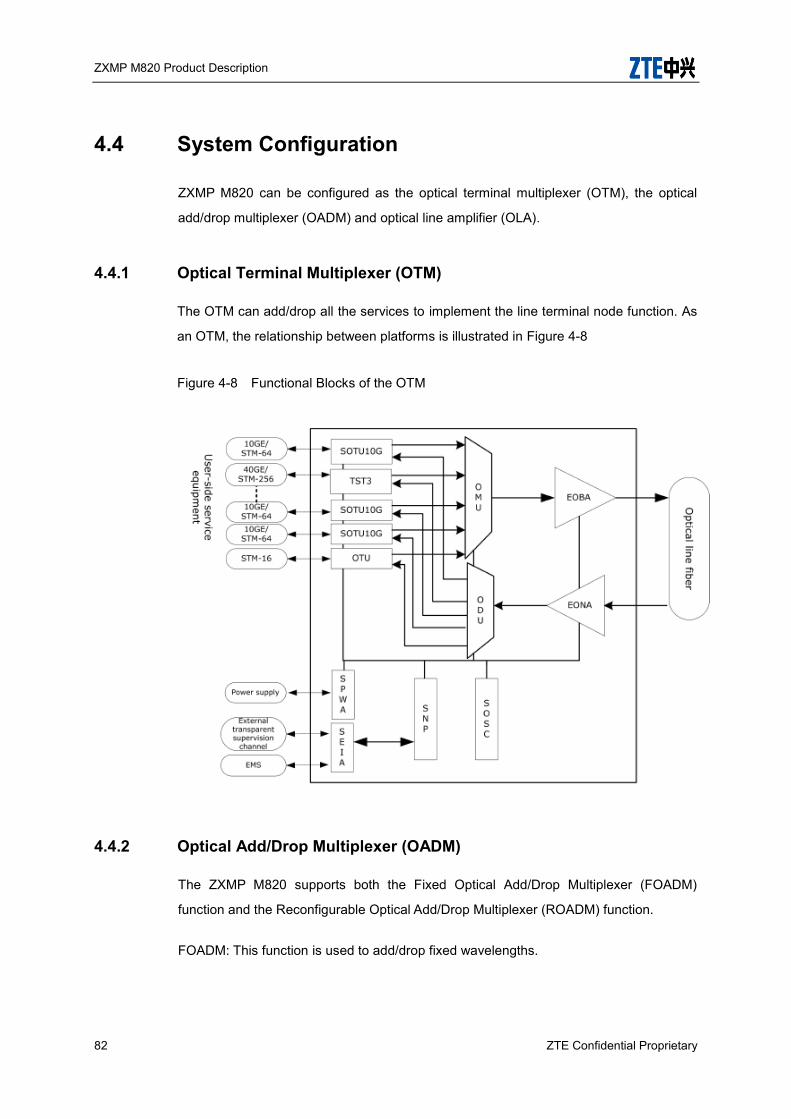
ZXMP M820 Product Description
82 ZTE Confidential Proprietary
4.4 System Configuration
ZXMP M820 can be configured as the optical terminal multiplexer (OTM), the optical
add/drop multiplexer (OADM) and optical line amplifier (OLA).
4.4.1 Optical Terminal Multiplexer (OTM)
The OTM can add/drop all the services to implement the line terminal node function. As
an OTM, the relationship between platforms is illustrated in Figure 4-8
Figure 4-8 Functional Blocks of the OTM
4.4.2 Optical Add/Drop Multiplexer (OADM)
The ZXMP M820 supports both the Fixed Optical Add/Drop Multiplexer (FOADM)
function and the Reconfigurable Optical Add/Drop Multiplexer (ROADM) function.
FOADM: This function is used to add/drop fixed wavelengths.
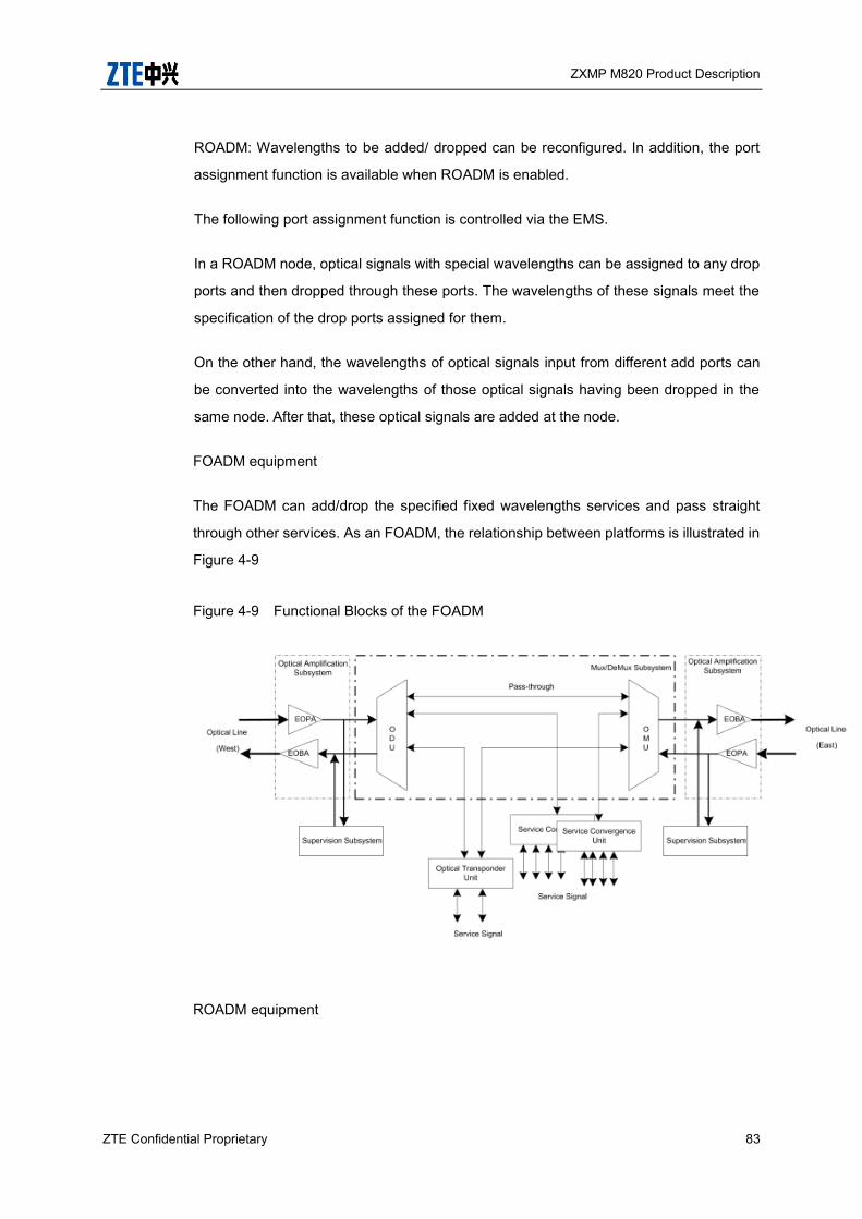
ZXMP M820 Product Description
ZTE Confidential Proprietary 83
ROADM: Wavelengths to be added/ dropped can be reconfigured. In addition, the port
assignment function is available when ROADM is enabled.
The following port assignment function is controlled via the EMS.
In a ROADM node, optical signals with special wavelengths can be assigned to any drop
ports and then dropped through these ports. The wavelengths of these signals meet the
specification of the drop ports assigned for them.
On the other hand, the wavelengths of optical signals input from different add ports can
be converted into the wavelengths of those optical signals having been dropped in the
same node. After that, these optical signals are added at the node.
FOADM equipment
The FOADM can add/drop the specified fixed wavelengths services and pass straight
through other services. As an FOADM, the relationship between platforms is illustrated in
Figure 4-9
Figure 4-9 Functional Blocks of the FOADM
ROADM equipment
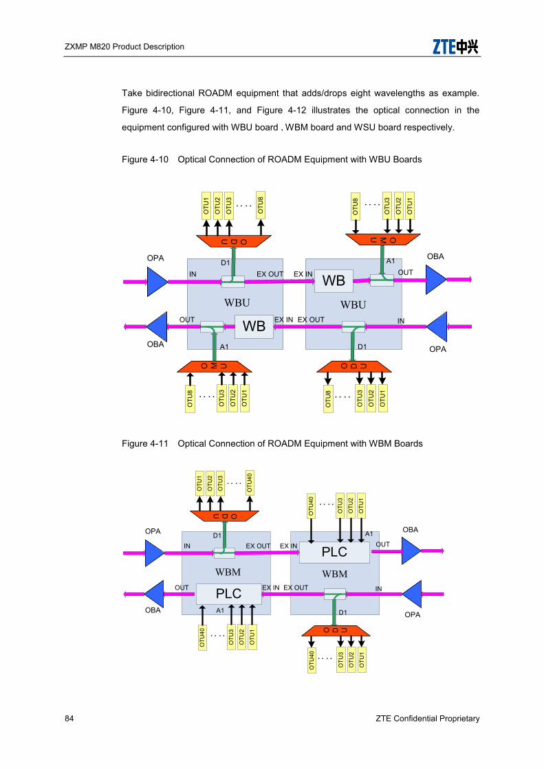
ZXMP M820 Product Description
84 ZTE Confidential Proprietary
Take bidirectional ROADM equipment that adds/drops eight wavelengths as example.
Figure 4-10, Figure 4-11, and Figure 4-12 illustrates the optical connection in the
equipment configured with WBU board ,WBM board and WSU board respectively.
Figure 4-10 Optical Connection of ROADM Equipment with WBU Boards
Figure 4-11 Optical Connection of ROADM Equipment with WBM Boards
OPA
ODU
OTU
1
OTU
2
OTU
3
OTU
8: :
O M U
OTU
1
OTU
2
OTU
3
OTU
8 ::WB
OBA
OPA
WB
OTU
1
OTU
2
OTU
3
OTU
8 ::
OMU
O D U
OTU
1
OTU
2
OTU
3
OTU
8 ::
OBA
IN EX OUTD1
EX IN
A1
OUT
EX IN
A1OUT
IN
D1
EX OUT
WBU WBU
OPA
ODU
OTU
1
OTU
2
OTU
3
OTU
40: :O
TU1
OTU
2
OTU
3
OTU
40 ::
PLC
OBA
OPA
PLC
OTU
1
OTU
2
OTU
3
OTU
40 ::
O D U
OTU
1
OTU
2
OTU
3
OTU
40 ::
OBA
IN EX OUTD1
EX IN
A1
OUT
EX IN
A1OUT
IN
D1
EX OUT
WBM WBM
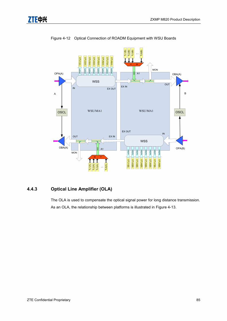
ZXMP M820 Product Description
ZTE Confidential Proprietary 85
Figure 4-12 Optical Connection of ROADM Equipment with WSU Boards
4.4.3 Optical Line Amplifier (OLA)
The OLA is used to compensate the optical signal power for long distance transmission.
As an OLA, the relationship between platforms is illustrated in Figure 4-13.
OPA(A)
OBA(A)
OSCL
TL8(
B)
TL3(
B)
TL2(
B)
TL1(
B)
:8:1
DR
OP1
AD
D
OTU
8(A)
OTU
3(A)
OTU
2(A)
OTU
1(A)
OTU
4(A)
OTU
5(A)
OTU
6(A)
OTU
7(A)
BA
OBA(A)
OPA(B)
OSCL
WSS
IN EX OUT
MONA1
EX INOUT
DR
OP2
DR
OP3
DR
OP4
DR
OP5
DR
OP6
DR
OP7
DR
OP8
WSS
DR
OP
7
DR
OP
6
DR
OP
5
DR
OP
4
DR
OP
3
DR
OP
2
DR
OP
1
TL8(
A)
TL3(
A)
TL2(
A)
TL1(
A) :
8 : 1A
DD
INEX OUT
OTU
3(B)
OTU
2(B)
OTU
1(B)
OTU
4(B)
OTU
5(B)
OTU
6(B)
OTU
7(B)
EX INOUT
MONA1
WSU/MA1 WSU/MA1
DR
OP
8O
TU8(B
)
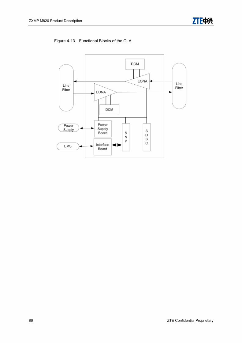
ZXMP M820 Product Description
86 ZTE Confidential Proprietary
Figure 4-13 Functional Blocks of the OLA
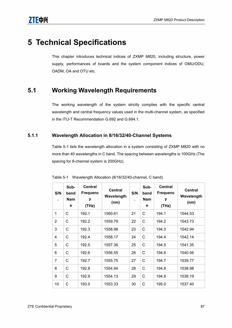
ZXMP M820 Product Description
ZTE Confidential Proprietary 87
5 Technical Specifications This chapter introduces technical indices of ZXMP M820, including structure, power
supply, performances of boards and the system component indices of OMU/ODU,
OADM, OA and OTU etc.
5.1 Working Wavelength Requirements
The working wavelength of the system strictly complies with the specific central
wavelength and central frequency values used in the multi-channel system, as specified
in the ITU-T Recommendation G.692 and G.694.1.
5.1.1 Wavelength Allocation in 8/16/32/40-Channel Systems
Table 5-1 lists the wavelength allocation in a system consisting of ZXMP M820 with no
more than 40 wavelengths in C band. The spacing between wavelengths is 100GHz (The
spacing for 8-channel system is 200GHz).
Table 5-1 Wavelength Allocation (8/16/32/40-channel, C band)
S/N.
Sub-band Nam
e
Central Frequenc
y
(THz)
Central Wavelength
(nm)
S/N.
Sub-band Nam
e
Central Frequenc
y
(THz)
Central Wavelength
(nm)
1 C 192.1 1560.61 21 C 194.1 1544.53
2 C 192.2 1559.79 22 C 194.2 1543.73
3 C 192.3 1558.98 23 C 194.3 1542.94
4 C 192.4 1558.17 24 C 194.4 1542.14
5 C 192.5 1557.36 25 C 194.5 1541.35
6 C 192.6 1556.55 26 C 194.6 1540.56
7 C 192.7 1555.75 27 C 194.7 1539.77
8 C 192.8 1554.94 28 C 194.8 1538.98
9 C 192.9 1554.13 29 C 194.9 1538.19
10 C 193.0 1553.33 30 C 195.0 1537.40
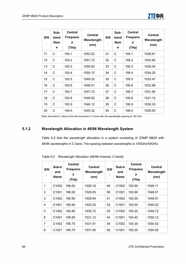
ZXMP M820 Product Description
88 ZTE Confidential Proprietary
S/N.
Sub-band Nam
e
Central Frequenc
y
(THz)
Central Wavelength
(nm)
S/N.
Sub-band Nam
e
Central Frequenc
y
(THz)
Central Wavelength
(nm)
11 C 193.1 1552.52 31 C 195.1 1536.61
12 C 193.2 1551.72 32 C 195.2 1535.82
13 C 193.3 1550.92 33 C 195.3 1535.04
14 C 193.4 1550.12 34 C 195.4 1534.25
15 C 193.5 1549.32 35 C 195.5 1533.47
16 C 193.6 1548.51 36 C 195.6 1532.68
17 C 193.7 1547.72 37 C 195.7 1531.90
18 C 193.8 1546.92 38 C 195.8 1531.12
19 C 193.9 1546.12 39 C 195.9 1530.33
20 C 194.0 1545.32 40 C 196.0 1529.55
Note: Sub-band C refers to the first sub-band in C band with the wavelength spacing at 100 GHz.
5.1.2 Wavelength Allocation in 48/96 Wavelength System
Table 5-2 lists the wavelength allocation in a system consisting of ZXMP M820 with
48/96 wavelengths in C band. The spacing between wavelengths is 100GHz/50GHz.
Table 5-2 Wavelength Allocation (48/96-channel, C band)
S/N.
Sub-band
Name
Central Frequenc
y
(THz)
Central Wavelength
(nm)
S/N.
Sub-band
Name
Central Frequenc
y
(THz)
Central Wavelength
(nm)
1 C1002 196.05 1529.16 49 C1002 193.65 1548.11
2 C1001 196.00 1529.55 50 C1001 193.60 1548.51
3 C1002 195.95 1529.94 51 C1002 193.55 1548.91
4 C1001 195.90 1530.33 52 C1001 193.50 1549.32
5 C1002 195.85 1530.72 53 C1002 193.45 1549.72
6 C1001 195.80 1531.12 54 C1001 193.40 1550.12
7 C1002 195.75 1531.51 55 C1002 193.35 1550.52
8 C1001 195.70 1531.90 56 C1001 193.30 1550.92
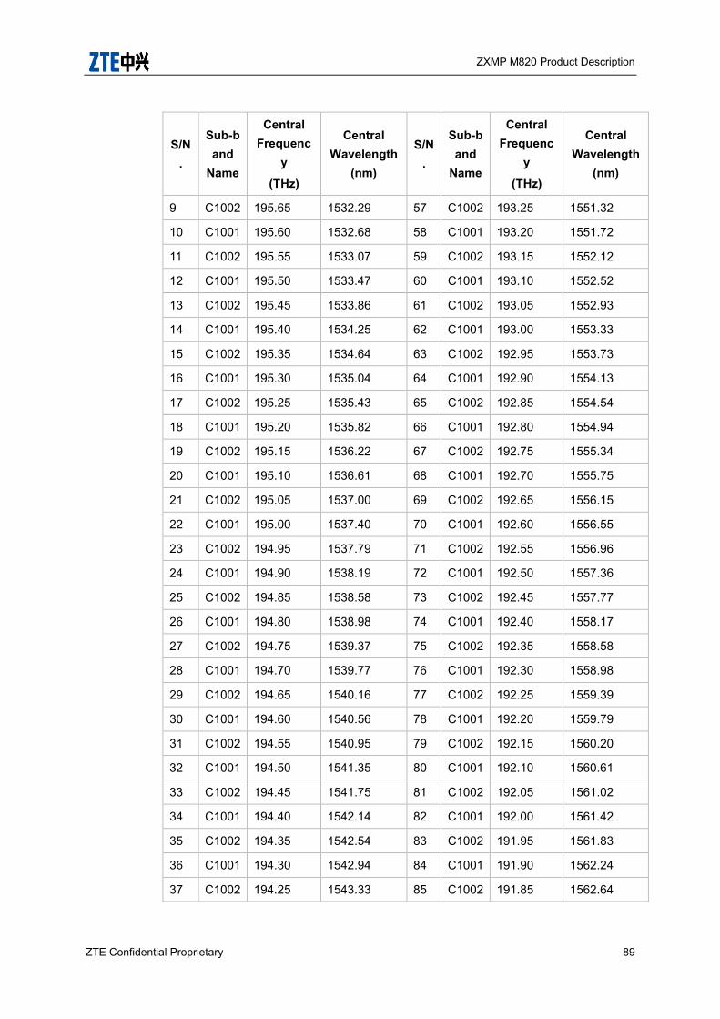
ZXMP M820 Product Description
ZTE Confidential Proprietary 89
S/N.
Sub-band
Name
Central Frequenc
y
(THz)
Central Wavelength
(nm)
S/N.
Sub-band
Name
Central Frequenc
y
(THz)
Central Wavelength
(nm)
9 C1002 195.65 1532.29 57 C1002 193.25 1551.32
10 C1001 195.60 1532.68 58 C1001 193.20 1551.72
11 C1002 195.55 1533.07 59 C1002 193.15 1552.12
12 C1001 195.50 1533.47 60 C1001 193.10 1552.52
13 C1002 195.45 1533.86 61 C1002 193.05 1552.93
14 C1001 195.40 1534.25 62 C1001 193.00 1553.33
15 C1002 195.35 1534.64 63 C1002 192.95 1553.73
16 C1001 195.30 1535.04 64 C1001 192.90 1554.13
17 C1002 195.25 1535.43 65 C1002 192.85 1554.54
18 C1001 195.20 1535.82 66 C1001 192.80 1554.94
19 C1002 195.15 1536.22 67 C1002 192.75 1555.34
20 C1001 195.10 1536.61 68 C1001 192.70 1555.75
21 C1002 195.05 1537.00 69 C1002 192.65 1556.15
22 C1001 195.00 1537.40 70 C1001 192.60 1556.55
23 C1002 194.95 1537.79 71 C1002 192.55 1556.96
24 C1001 194.90 1538.19 72 C1001 192.50 1557.36
25 C1002 194.85 1538.58 73 C1002 192.45 1557.77
26 C1001 194.80 1538.98 74 C1001 192.40 1558.17
27 C1002 194.75 1539.37 75 C1002 192.35 1558.58
28 C1001 194.70 1539.77 76 C1001 192.30 1558.98
29 C1002 194.65 1540.16 77 C1002 192.25 1559.39
30 C1001 194.60 1540.56 78 C1001 192.20 1559.79
31 C1002 194.55 1540.95 79 C1002 192.15 1560.20
32 C1001 194.50 1541.35 80 C1001 192.10 1560.61
33 C1002 194.45 1541.75 81 C1002 192.05 1561.02
34 C1001 194.40 1542.14 82 C1001 192.00 1561.42
35 C1002 194.35 1542.54 83 C1002 191.95 1561.83
36 C1001 194.30 1542.94 84 C1001 191.90 1562.24
37 C1002 194.25 1543.33 85 C1002 191.85 1562.64

ZXMP M820 Product Description
90 ZTE Confidential Proprietary
S/N.
Sub-band
Name
Central Frequenc
y
(THz)
Central Wavelength
(nm)
S/N.
Sub-band
Name
Central Frequenc
y
(THz)
Central Wavelength
(nm)
38 C1001 194.20 1543.73 86 C1001 191.80 1563.05
39 C1002 194.15 1544.13 87 C1002 191.75 1563.46
40 C1001 194.10 1544.53 88 C1001 191.70 1563.87
41 C1002 194.05 1544.92 89 C1002 191.65 1564.27
42 C1001 194.00 1545.32 90 C1001 191.60 1564.68
43 C1002 193.95 1545.72 91 C1002 191.55 1565.09
44 C1001 193.90 1546.12 92 C1001 191.50 1565.5
45 C1002 193.85 1546.52 93 C1002 191.45 1565.91
46 C1001 193.80 1546.92 94 C1001 191.40 1566.32
47 C1002 193.75 1547.32 95 C1002 191.35 1566.73
48 C1001 193.70 1547.72 96 C1001 191.30 1567.14
Note: Sub-band C1001 and C1002 respectively refer to the first and the second sub-bands in C band with the
wavelength spacing at 100 GHz. Each sub-band includes 48 wavelengths.
5.1.3 Wavelength Allocation in 80/160 Wavelength System
Table 5-3 lists the wavelength allocation in a system consisting of ZXMP M820 with 80
wavelengths in C band. The spacing between wavelengths is 50 GHz.
Table 5-3 Wavelength Allocation (80-channel, C band)
S/N.
Sub-ban
d Nam
e
Central Frequency
(THz)
Central Wavelength
(nm)
S/N.
Sub-band
Name
Central Frequency
(THz)
Central Wavelength
(nm)
1 C+ 196.05 1529.16 41 C+ 194.05 1544.92
2 C 196.00 1529.55 42 C 194.00 1545.32
3 C+ 195.95 1529.94 43 C+ 193.95 1545.72
4 C 195.90 1530.33 44 C 193.90 1546.12
5 C+ 195.85 1530.72 45 C+ 193.85 1546.52
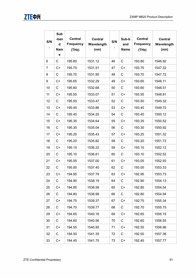
ZXMP M820 Product Description
ZTE Confidential Proprietary 91
S/N.
Sub-ban
d Nam
e
Central Frequency
(THz)
Central Wavelength
(nm)
S/N.
Sub-band
Name
Central Frequency
(THz)
Central Wavelength
(nm)
6 C 195.80 1531.12 46 C 193.80 1546.92
7 C+ 195.75 1531.51 47 C+ 193.75 1547.32
8 C 195.70 1531.90 48 C 193.70 1547.72
9 C+ 195.65 1532.29 49 C+ 193.65 1548.11
10 C 195.60 1532.68 50 C 193.60 1548.51
11 C+ 195.55 1533.07 51 C+ 193.55 1548.91
12 C 195.50 1533.47 52 C 193.50 1549.32
13 C+ 195.45 1533.86 53 C+ 193.45 1549.72
14 C 195.40 1534.25 54 C 193.40 1550.12
15 C+ 195.35 1534.64 55 C+ 193.35 1550.52
16 C 195.30 1535.04 56 C 193.30 1550.92
17 C+ 195.25 1535.43 57 C+ 193.25 1551.32
18 C 195.20 1535.82 58 C 193.20 1551.72
19 C+ 195.15 1536.22 59 C+ 193.15 1552.12
20 C 195.10 1536.61 60 C 193.10 1552.52
21 C+ 195.05 1537.00 61 C+ 193.05 1552.93
22 C 195.00 1537.40 62 C 193.00 1553.33
23 C+ 194.95 1537.79 63 C+ 192.95 1553.73
24 C 194.90 1538.19 64 C 192.90 1554.13
25 C+ 194.85 1538.58 65 C+ 192.85 1554.54
26 C 194.80 1538.98 66 C 192.80 1554.94
27 C+ 194.75 1539.37 67 C+ 192.75 1555.34
28 C 194.70 1539.77 68 C 192.70 1555.75
29 C+ 194.65 1540.16 69 C+ 192.65 1556.15
30 C 194.60 1540.56 70 C 192.60 1556.55
31 C+ 194.55 1540.95 71 C+ 192.55 1556.96
32 C 194.50 1541.35 72 C 192.50 1557.36
33 C+ 194.45 1541.75 73 C+ 192.45 1557.77

ZXMP M820 Product Description
92 ZTE Confidential Proprietary
S/N.
Sub-ban
d Nam
e
Central Frequency
(THz)
Central Wavelength
(nm)
S/N.
Sub-band
Name
Central Frequency
(THz)
Central Wavelength
(nm)
34 C 194.40 1542.14 74 C 192.40 1558.17
35 C+ 194.35 1542.54 75 C+ 192.35 1558.58
36 C 194.30 1542.94 76 C 192.30 1558.98
37 C+ 194.25 1543.33 77 C+ 192.25 1559.39
38 C 194.20 1543.73 78 C 192.20 1559.79
39 C+ 194.15 1544.13 79 C+ 192.15 1560.20
40 C 194.10 1544.53 80 C 192.10 1560.61
Note: Sub-band C and C+ respectively refer to the first and the second sub-bands in C band with the wavelength
spacing at 100 GHz. Each sub-band includes 40 wavelengths.
Table 5-4 lists the wavelength allocation in a system consisting of ZXMP M820 with 80
wavelengths in L band. The spacing between wavelengths is 50GHz.
Table 5-4 Wavelength Allocation (80-channel, L band)
S/N.
Sub-ban
d Nam
e
Central Frequency
(THz)
Central Wavelength
(nm)
S/N.
Sub-band
Name
Central Frequency
(THz)
Central Wavelength
(nm)
1 L 190.90 1570.42 41 L 188.90 1587.04
2 L+ 190.85 1570.83 42 L+ 188.85 1587.46
3 L 190.80 1571.24 43 L 188.80 1587.88
4 L+ 190.75 1571.65 44 L+ 188.75 1588.30
5 L 190.70 1572.06 45 L 188.70 1588.73
6 L+ 190.65 1572.48 46 L+ 188.65 1589.15
7 L 190.60 1572.89 47 L 188.60 1589.57
8 L+ 190.55 1573.30 48 L+ 188.55 1589.99
9 L 190.50 1573.71 49 L 188.50 1590.41
10 L+ 190.45 1574.13 50 L+ 188.45 1590.83

ZXMP M820 Product Description
ZTE Confidential Proprietary 93
S/N.
Sub-ban
d Nam
e
Central Frequency
(THz)
Central Wavelength
(nm)
S/N.
Sub-band
Name
Central Frequency
(THz)
Central Wavelength
(nm)
11 L 190.40 1574.54 51 L 188.40 1591.26
12 L+ 190.35 1574.95 52 L+ 188.35 1591.68
13 L 190.30 1575.37 53 L 188.30 1592.10
14 L+ 190.25 1575.78 54 L+ 188.25 1592.52
15 L 190.20 1576.20 55 L 188.20 1592.95
16 L+ 190.15 1576.61 56 L+ 188.15 1593.37
17 L 190.10 1577.03 57 L 188.10 1593.79
18 L+ 190.05 1577.44 58 L+ 188.05 1594.22
19 L 190.00 1577.86 59 L 188.00 1594.64
20 L+ 189.95 1578.27 60 L+ 187.95 1595.06
21 L 189.90 1578.69 61 L 187.90 1595.49
22 L+ 189.85 1579.10 62 L+ 187.85 1595.91
23 L 189.80 1579.52 63 L 187.80 1596.34
24 L+ 189.75 1579.93 64 L+ 187.75 1596.76
25 L 189.70 1580.35 65 L 187.70 1597.19
26 L+ 189.65 1580.77 66 L+ 187.65 1597.62
27 L 189.60 1581.18 67 L 187.60 1598.04
28 L+ 189.55 1581.60 68 L+ 187.55 1598.47
29 L 189.50 1582.02 69 L 187.50 1598.89
30 L+ 189.45 1582.44 70 L+ 187.45 1599.32
31 L 189.40 1582.85 71 L 187.40 1599.75
32 L+ 189.35 1583.27 72 L+ 187.35 1600.17
33 L 189.30 1583.69 73 L 187.30 1600.60
34 L+ 189.25 1584.11 74 L+ 187.25 1601.03
35 L 189.20 1584.53 75 L 187.20 1601.46
36 L+ 189.15 1584.95 76 L+ 187.15 1601.88
37 L 189.10 1585.36 77 L 187.10 1602.31
38 L+ 189.05 1585.78 78 L+ 187.05 1602.74
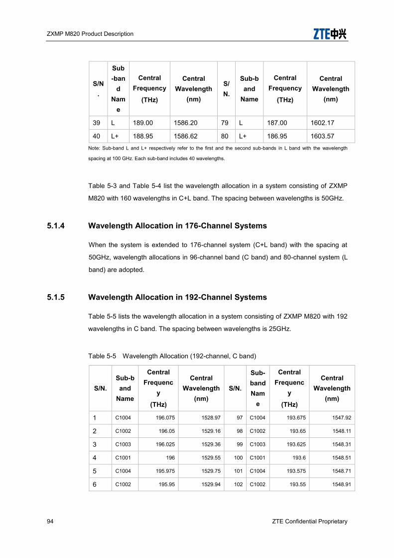
ZXMP M820 Product Description
94 ZTE Confidential Proprietary
S/N.
Sub-ban
d Nam
e
Central Frequency
(THz)
Central Wavelength
(nm)
S/N.
Sub-band
Name
Central Frequency
(THz)
Central Wavelength
(nm)
39 L 189.00 1586.20 79 L 187.00 1602.17
40 L+ 188.95 1586.62 80 L+ 186.95 1603.57
Note: Sub-band L and L+ respectively refer to the first and the second sub-bands in L band with the wavelength
spacing at 100 GHz. Each sub-band includes 40 wavelengths.
Table 5-3 and Table 5-4 list the wavelength allocation in a system consisting of ZXMP
M820 with 160 wavelengths in C+L band. The spacing between wavelengths is 50GHz.
5.1.4 Wavelength Allocation in 176-Channel Systems
When the system is extended to 176-channel system (C+L band) with the spacing at
50GHz, wavelength allocations in 96-channel band (C band) and 80-channel system (L
band) are adopted.
5.1.5 Wavelength Allocation in 192-Channel Systems
Table 5-5 lists the wavelength allocation in a system consisting of ZXMP M820 with 192
wavelengths in C band. The spacing between wavelengths is 25GHz.
Table 5-5 Wavelength Allocation (192-channel, C band)
S/N. Sub-band
Name
Central Frequenc
y
(THz)
Central Wavelength
(nm) S/N.
Sub-band Nam
e
Central Frequenc
y
(THz)
Central Wavelength
(nm)
1 C1004 196.075 1528.97 97 C1004 193.675 1547.92
2 C1002 196.05 1529.16 98 C1002 193.65 1548.11
3 C1003 196.025 1529.36 99 C1003 193.625 1548.31
4 C1001 196 1529.55 100 C1001 193.6 1548.51
5 C1004 195.975 1529.75 101 C1004 193.575 1548.71
6 C1002 195.95 1529.94 102 C1002 193.55 1548.91
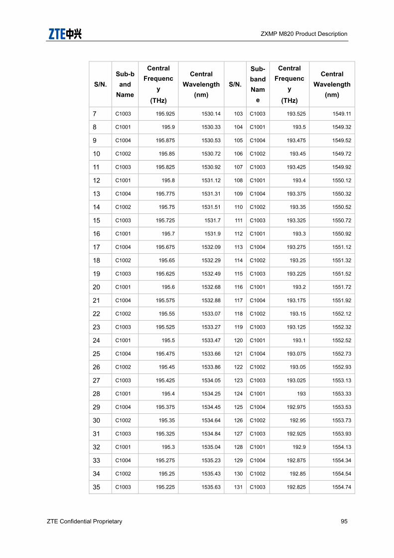
ZXMP M820 Product Description
ZTE Confidential Proprietary 95
S/N. Sub-band
Name
Central Frequenc
y
(THz)
Central Wavelength
(nm) S/N.
Sub-band Nam
e
Central Frequenc
y
(THz)
Central Wavelength
(nm)
7 C1003 195.925 1530.14 103 C1003 193.525 1549.11
8 C1001 195.9 1530.33 104 C1001 193.5 1549.32
9 C1004 195.875 1530.53 105 C1004 193.475 1549.52
10 C1002 195.85 1530.72 106 C1002 193.45 1549.72
11 C1003 195.825 1530.92 107 C1003 193.425 1549.92
12 C1001 195.8 1531.12 108 C1001 193.4 1550.12
13 C1004 195.775 1531.31 109 C1004 193.375 1550.32
14 C1002 195.75 1531.51 110 C1002 193.35 1550.52
15 C1003 195.725 1531.7 111 C1003 193.325 1550.72
16 C1001 195.7 1531.9 112 C1001 193.3 1550.92
17 C1004 195.675 1532.09 113 C1004 193.275 1551.12
18 C1002 195.65 1532.29 114 C1002 193.25 1551.32
19 C1003 195.625 1532.49 115 C1003 193.225 1551.52
20 C1001 195.6 1532.68 116 C1001 193.2 1551.72
21 C1004 195.575 1532.88 117 C1004 193.175 1551.92
22 C1002 195.55 1533.07 118 C1002 193.15 1552.12
23 C1003 195.525 1533.27 119 C1003 193.125 1552.32
24 C1001 195.5 1533.47 120 C1001 193.1 1552.52
25 C1004 195.475 1533.66 121 C1004 193.075 1552.73
26 C1002 195.45 1533.86 122 C1002 193.05 1552.93
27 C1003 195.425 1534.05 123 C1003 193.025 1553.13
28 C1001 195.4 1534.25 124 C1001 193 1553.33
29 C1004 195.375 1534.45 125 C1004 192.975 1553.53
30 C1002 195.35 1534.64 126 C1002 192.95 1553.73
31 C1003 195.325 1534.84 127 C1003 192.925 1553.93
32 C1001 195.3 1535.04 128 C1001 192.9 1554.13
33 C1004 195.275 1535.23 129 C1004 192.875 1554.34
34 C1002 195.25 1535.43 130 C1002 192.85 1554.54
35 C1003 195.225 1535.63 131 C1003 192.825 1554.74
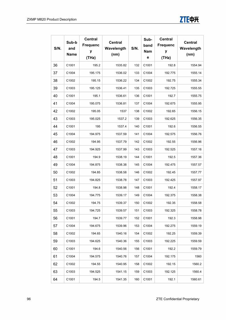
ZXMP M820 Product Description
96 ZTE Confidential Proprietary
S/N. Sub-band
Name
Central Frequenc
y
(THz)
Central Wavelength
(nm) S/N.
Sub-band Nam
e
Central Frequenc
y
(THz)
Central Wavelength
(nm)
36 C1001 195.2 1535.82 132 C1001 192.8 1554.94
37 C1004 195.175 1536.02 133 C1004 192.775 1555.14
38 C1002 195.15 1536.22 134 C1002 192.75 1555.34
39 C1003 195.125 1536.41 135 C1003 192.725 1555.55
40 C1001 195.1 1536.61 136 C1001 192.7 1555.75
41 C1004 195.075 1536.81 137 C1004 192.675 1555.95
42 C1002 195.05 1537 138 C1002 192.65 1556.15
43 C1003 195.025 1537.2 139 C1003 192.625 1556.35
44 C1001 195 1537.4 140 C1001 192.6 1556.55
45 C1004 194.975 1537.59 141 C1004 192.575 1556.76
46 C1002 194.95 1537.79 142 C1002 192.55 1556.96
47 C1003 194.925 1537.99 143 C1003 192.525 1557.16
48 C1001 194.9 1538.19 144 C1001 192.5 1557.36
49 C1004 194.875 1538.38 145 C1004 192.475 1557.57
50 C1002 194.85 1538.58 146 C1002 192.45 1557.77
51 C1003 194.825 1538.78 147 C1003 192.425 1557.97
52 C1001 194.8 1538.98 148 C1001 192.4 1558.17
53 C1004 194.775 1539.17 149 C1004 192.375 1558.38
54 C1002 194.75 1539.37 150 C1002 192.35 1558.58
55 C1003 194.725 1539.57 151 C1003 192.325 1558.78
56 C1001 194.7 1539.77 152 C1001 192.3 1558.98
57 C1004 194.675 1539.96 153 C1004 192.275 1559.19
58 C1002 194.65 1540.16 154 C1002 192.25 1559.39
59 C1003 194.625 1540.36 155 C1003 192.225 1559.59
60 C1001 194.6 1540.56 156 C1001 192.2 1559.79
61 C1004 194.575 1540.76 157 C1004 192.175 1560
62 C1002 194.55 1540.95 158 C1002 192.15 1560.2
63 C1003 194.525 1541.15 159 C1003 192.125 1560.4
64 C1001 194.5 1541.35 160 C1001 192.1 1560.61

ZXMP M820 Product Description
ZTE Confidential Proprietary 97
S/N. Sub-band
Name
Central Frequenc
y
(THz)
Central Wavelength
(nm) S/N.
Sub-band Nam
e
Central Frequenc
y
(THz)
Central Wavelength
(nm)
65 C1004 194.475 1541.55 161 C1004 192.075 1560.81
66 C1002 194.45 1541.75 162 C1002 192.05 1561.02
67 C1003 194.425 1541.94 163 C1003 192.025 1561.22
68 C1001 194.4 1542.14 164 C1001 192 1561.42
69 C1004 194.375 1542.34 165 C1004 191.975 1561.62
70 C1002 194.35 1542.54 166 C1002 191.95 1561.83
71 C1003 194.325 1542.74 167 C1003 191.925 1562.03
72 C1001 194.3 1542.94 168 C1001 191.9 1562.24
73 C1004 194.275 1543.13 169 C1004 191.875 1562.44
74 C1002 194.25 1543.33 170 C1002 191.85 1562.64
75 C1003 194.225 1543.53 171 C1003 191.825 1562.84
76 C1001 194.2 1543.73 172 C1001 191.8 1563.05
77 C1004 194.175 1543.93 173 C1004 191.775 1563.25
78 C1002 194.15 1544.13 174 C1002 191.75 1563.46
79 C1003 194.125 1544.33 175 C1003 191.725 1563.66
80 C1001 194.1 1544.53 176 C1001 191.7 1563.87
81 C1004 194.075 1544.72 177 C1004 191.675 1564.07
82 C1002 194.05 1544.92 178 C1002 191.65 1564.27
83 C1003 194.025 1545.12 179 C1003 191.625 1564.47
84 C1001 194 1545.32 180 C1001 191.6 1564.68
85 C1004 193.975 1545.52 181 C1004 191.575 1564.88
86 C1002 193.95 1545.72 182 C1002 191.55 1565.09
87 C1003 193.925 1545.92 183 C1003 191.525 1565.29
88 C1001 193.9 1546.12 184 C1001 191.5 1565.5
89 C1004 193.875 1546.32 185 C1004 191.475 1565.7
90 C1002 193.85 1546.52 186 C1002 191.45 1565.91
91 C1003 193.825 1546.72 187 C1003 191.425 1566.11
92 C1001 193.8 1546.92 188 C1001 191.4 1566.32
93 C1004 193.775 1547.12 189 C1004 191.375 1566.52
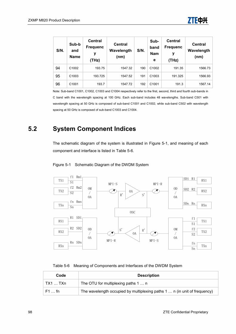
ZXMP M820 Product Description
98 ZTE Confidential Proprietary
S/N. Sub-band
Name
Central Frequenc
y
(THz)
Central Wavelength
(nm) S/N.
Sub-band Nam
e
Central Frequenc
y
(THz)
Central Wavelength
(nm)
94 C1002 193.75 1547.32 190 C1002 191.35 1566.73
95 C1003 193.725 1547.52 191 C1003 191.325 1566.93
96 C1001 193.7 1547.72 192 C1001 191.3 1567.14
Note: Sub-band C1001, C1002, C1003 and C1004 respectively refer to the first, second, third and fourth sub-bands in
C band with the wavelength spacing at 100 GHz. Each sub-band includes 48 wavelengths. Sub-band C501 with
wavelength spacing at 50 GHz is composed of sub-band C1001 and C1002, while sub-band C502 with wavelength
spacing at 50 GHz is composed of sub-band C1003 and C1004.
5.2 System Component Indices
The schematic diagram of the system is illustrated in Figure 5-1, and meaning of each
component and interface is listed in Table 5-6.
Figure 5-1 Schematic Diagram of the DWDM System
Table 5-6 Meaning of Components and Interfaces of the DWDM System
Code Description
TX1 … TXn The OTU for multiplexing paths 1 … n
F1 … fn The wavelength occupied by multiplexing paths 1 … n (in unit of frequency)
OM/OA
OAOD/OA
TX1
TX2
TXn
RX1
RX2
RXn
OM/OA
OD/OA
RX1
RX2
RXn
TX1
TX2
TXn
OSC
Rm1
Rm2
Rmn
MPI-R
MPI-S
MPI-S
MPI-R
R1
R2
Rn
R1
R2
Rn
S1
S2
Sn
f1
f2
fn
S1
S2
Sn
f1
f2
fnSDn
SD2
SD1
SDn
SD2
SD1
R'
S' R'
S'
OA

ZXMP M820 Product Description
ZTE Confidential Proprietary 99
Code Description
S1 … Sn Reference points on the optical fibre at the output optical connectors of the transmitters for channels 1...n respectively
RM1 … RMn Reference points on the optical fibre just before the OM/OA input optical connectors for channels 1...n respectively
OM Optical Multiplexer
OA Optical amplifier
OD Optical demultiplexer
MPI Main optical channel
MPI-S Reference point on the optical fibre just after the OM/OA output optical connector
MPI-R Reference point on the optical fibre just before the OA/OD input optical connector
R’ Reference point on the optical fibre just before the line OA input optical connector
S’ Reference point just after the line OA output optical connector
SD1 … SDn Reference points at the OA/OD output optical connectors
R1 … Rn Reference points at the inputs to the receiver optical connectors.
RX1 … RXn The OTU for multiplexing paths 1 … n
OSC Optical supervisory channel
5.3 OMU/ODU Unit Specifications
Technical specifications of OM U and ODU for ZXMP M820 are listed below:
5.3.1 Specifications of OMU Board
The OMU technical specifications of ZXMP M820 are listed in Table 5-7.
Table 5-7 Technical specifications of OMU Board
Item Unit Specifications (32
Channels) Specifications (40
Channels)
Specifications
(48 Chann
Specifications (80 Channels)
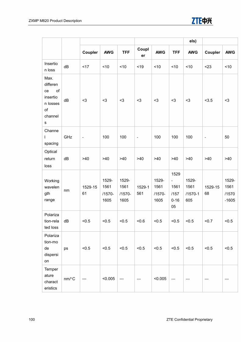
ZXMP M820 Product Description
100 ZTE Confidential Proprietary
els)
Coupler AWG TFF Coupl
er AWG TFF AWG Coupler AWG
Insertion loss
dB <17 <10 <10 <19 <10 <10 <10 <23 <10
Max. difference of insertion losses of channels
dB <3 <3 <3 <3 <3 <3 <3 <3.5 <3
Channel spacing
GHz - 100 100 - 100 100 100 - 50
Optical
return
loss
dB >40 >40 >40 >40 >40 >40 >40 >40 >40
Working wavelength range
nm 1529-1561
1529- 1561
/1570-1605
1529- 1561
/1570-1605
1529-1561
1529- 1561
/1570-1605
1529- 1561
/1570-1605
1529- 1561
/1570-1605
1529-1568
1529- 1561
/1570-1605
Polarization-related loss
dB <0.5 <0.5 <0.5 <0.6 <0.5 <0.5 <0.5 <0.7 <0.5
Polarization-mode dispersion
ps <0.5 <0.5 <0.5 <0.5 <0.5 <0.5 <0.5 <0.5 <0.5
Temperature characteristics
nm/C --- <0.005 --- --- <0.005 --- --- --- ---

ZXMP M820 Product Description
ZTE Confidential Proprietary 101
Note: 1529 nm ~ 1561 nm corresponds to the C band OMU, while 1570nm ~ 1605 nm corresponds to the L band
OMU.
5.3.2 Specifications of ODU Board
Technical specifications of ZXMP M820 ODU are listed in Table 5-8.
Table 5-8 Technical specifications of ODU Board
Item Unit
Specifications (32 Channels)
Specifications (40 Channels)
Specifications
(48 Channel
s)
Specifications (80
Channels)
AWG TFF AWG TFF AWG AWG
Insertion loss
dB < 10 < 10 < 10 < 10 < 10 < 10
Max. difference of insertion losses of channels
dB < 3 < 3 < 3 < 3 < 3 < 3
Channel spacing
GHz 100 100 100 100 100 50
Optical return
loss
dB > 40 > 40 > 40 > 40 > 40 > 40
Working wavelength range
nm
1529-1561
/ 1570-1605
1529-1561
/ 1570-1605
1529-1561
/ 1570-1605
1529-1561
/1570-1605
1529-1568
/ 1570-1605
1529-1561
/ 1570-1605
Separation of adjacent channel
dB > 25 > 25 > 25 > 25 > 25 > 25
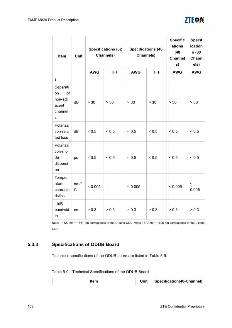
ZXMP M820 Product Description
102 ZTE Confidential Proprietary
Item Unit
Specifications (32 Channels)
Specifications (40 Channels)
Specifications
(48 Channel
s)
Specifications (80
Channels)
AWG TFF AWG TFF AWG AWG
s
Separation of non-adjacent channels
dB > 30 > 30 > 30 > 30 > 30 > 30
Polarization-related loss
dB < 0.5 < 0.5 < 0.5 < 0.5 < 0.5 < 0.5
Polarization-mode dispersion
ps < 0.5 < 0.5 < 0.5 < 0.5 < 0.5 < 0.5
Temperature characteristics
nm/C
< 0.005 --- < 0.005 --- < 0.005 < 0.005
-1dB bandwidth
nm > 0.3 > 0.3 > 0.3 > 0.3 > 0.3 > 0.3
Note: 1529 nm ~ 1561 nm corresponds to the C band ODU, while 1570 nm ~ 1605 nm corresponds to the L band
ODU.
5.3.3 Specifications of ODUB Board
Technical specifications of the ODUB board are listed in Table 5-9.
Table 5-9 Technical Specifications of the ODUB Board
Item Unit Specification(40-Channel)
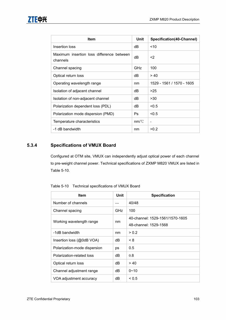
ZXMP M820 Product Description
ZTE Confidential Proprietary 103
Item Unit Specification(40-Channel)
Insertion loss dB <10
Maximum insertion loss difference between channels
dB <2
Channel spacing GHz 100
Optical return loss dB > 40
Operating wavelength range nm 1529 - 1561 / 1570 - 1605
Isolation of adjacent channel dB >25
Isolation of non-adjacent channel dB >30
Polarization dependent loss (PDL) dB <0.5
Polarization mode dispersion (PMD) Ps <0.5
Temperature characteristics nm/℃ -
-1 dB bandwidth nm >0.2
5.3.4 Specifications of VMUX Board
Configured at OTM site, VMUX can independently adjust optical power of each channel
to pre-weight channel power. Technical specifications of ZXMP M820 VMUX are listed in
Table 5-10.
Table 5-10 Technical specifications of VMUX Board
Item Unit Specification
Number of channels --- 40/48
Channel spacing GHz 100
Working wavelength range nm 40-channel: 1529-1561/1570-1605
48-channel: 1529-1568
-1dB bandwidth nm > 0.2
Insertion loss (@0dB VOA) dB < 8
Polarization-mode dispersion ps 0.5
Polarization-related loss dB 0.8
Optical return loss dB > 40
Channel adjustment range dB 0~10
VOA adjustment accuracy dB < 0.5

ZXMP M820 Product Description
104 ZTE Confidential Proprietary
5.3.5 Specifications of VMUXB Board
Configured at OTM site, VMUX can independently adjust optical power of each channel
to pre-weight channel power. Technical specifications of ZXMP M820 VMUXB are listed
in Table 5-11.
Table 5-11 Technical specifications of VMUXB Board
Item Unit Specification
Number of channels --- 40
Channel spacing GHz 100
Working wavelength range nm 40-channel: 1529-1561/1570-1605
-1dB bandwidth nm > 0.2
Insertion loss (@0dB VOA) dB < 8
Polarization-mode dispersion ps 0.5
Polarization-related loss dB 0.8
Optical return loss dB > 40
Channel adjustment range dB 0~10
VOA adjustment accuracy dB < 0.5
5.3.6 Specifications of OCI Board
Technical specifications of the OCI board are illustrated in Table 5-12 and Table 5-13.
Table 5-12 Technical Specifications of the OCI Board (100GHz-50GHz)
Item Unit Specification
C band wavelength range nm 1529 - 1568
CE band wavelength range nm 1529-1568
L band wavelength range nm 1570 - 1605
Input optical power range dBm < +23
Input wavelength spacing GHz 100
Output wavelength spacing GHz 50
Insertion loss dB < 3
Max. difference of insertion losses of channels dB < 1

ZXMP M820 Product Description
ZTE Confidential Proprietary 105
Item Unit Specification
Optical return loss dB > 40
Separation of adjacent channels dB > 25
Separation of non-adjacent channels dB > 25
Polarization-related loss dB < 0.5
Polarization-mode dispersion ps < 0.5
-1dB bandwidth nm > 0.1
Table 5-13 Technical Specifications of the OCI Board (50GHz-25GHz)
Item Unit Specification
CE band wavelength range THz 1529-1568
Input optical power range dBm < +23
Input wavelength spacing GHz 50
Output wavelength spacing GHz 25
Insertion loss dB < 3
Max. difference of insertion losses of channels dB < 2
Optical return loss dB > 40
Isolation of de-multiplexing procedure dB > 21
Isolation of multiplexing procedure dB > 16
Polarization dependent loss (PDL) dB < 0.5
Polarization mode dispersion (PMD) ps < 0.2
-1dB bandwidth nm > 20
5.3.7 Specifications of OBM Board
Technical Specifications of the OBM Board for ZXMP M820 are listed in Table 5-14.
Table 5-14 Technical Specifications of the OBM Board
Item Unit Specification
C band wavelength range nm 1529 -1561
CE band wavelength range nm 1529-1568
L band wavelength range nm 1570 -1605

ZXMP M820 Product Description
106 ZTE Confidential Proprietary
Item Unit Specification
C band insertion loss dB < 1.5
CE band insertion loss dB < 1.5
L band insertion loss dB < 1.5
Isolation dB 15
Optical return loss dB > 40
Polarization-related loss dB < 0.5
Polarization-mode dispersion ps < 0.5
5.4 WSUA/WSUD & WBU Unit Specifications
Technical specifications of WBU are listed in Table 5-15.
Table 5-15 Technical specifications of WBU Board
Item Unit Specification
Optical Spectrum range nm 1529-1568
Channel spacing GHz 100
50
Channel quantity - 40/48
80/96
Straight insertion loss
A1/A2-OUT dB <1.5
IN-D1/D2 dB <4
EXIN-OUT dB <14
IN-EXOUT dB <4
Attenuation tunable range dB 0~15
Attenuation tunable precision(ER) dB <0.5
Blocked extinction ratio dB >35
Return loss dB >40
Maximum total input optical power dBm ≤25
Maximum Single-channel input optical power dBm ≤16

ZXMP M820 Product Description
ZTE Confidential Proprietary 107
Technical specifications of WSUA/WSUD for ZXMP M820 are listed in Table 5-16.
Table 5-16 Technical specifications of WSUA/WSUD Board
Item Unit Specification
WSUD WSUA
Optical Spectrum range nm 1529-1561 1529-1561
Channel spacing GHz 100 100
50 50
Channel quantity - 40 40
80 80
Straight insertion loss
A1-OUT dB <2 <2
A2-OUT dB <10 <10
IN-D1~D8 dB <6 <6
EXIN-OUT dB <9 <6
IN-EXOUT dB
<6(WSUD/MA1)
<16(WSUD/MA2)
<9(WSUA/MD1)
<16(WSUA/MD2)
Attenuation tunable range dB 0~15 0~15
Attenuation tunable precision(ER) dB <0.5 <0.5
Blocked extinction ratio dB >35 >35
Return loss dB >40 >40
Maximum total input optical power dBm ≤25 ≤25
Maximum Single-channel input optical power
dBm ≤16 ≤16
Technical specifications of WBM are listed in Table 5-17.
Table 5-17 Technical specifications of WBM Board
Item Unit Specification
Optical spectrum range nm 1529-1561
Channel spacing GHz 100
Channel quantity - 40
insertion loss An-OUT (n=1-40) dB <8
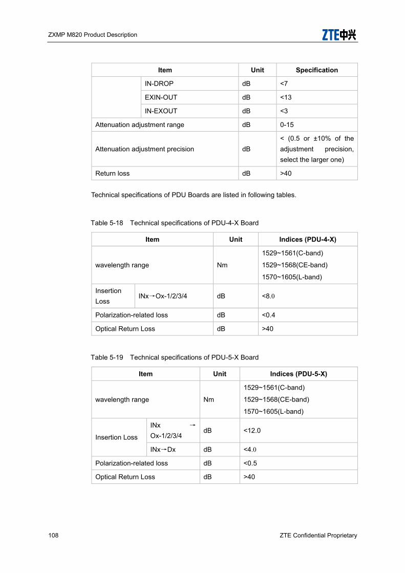
ZXMP M820 Product Description
108 ZTE Confidential Proprietary
Item Unit Specification
IN-DROP dB <7
EXIN-OUT dB <13
IN-EXOUT dB <3
Attenuation adjustment range dB 0-15
Attenuation adjustment precision dB < (0.5 or ±10% of the adjustment precision, select the larger one)
Return loss dB >40
Technical specifications of PDU Boards are listed in following tables.
Table 5-18 Technical specifications of PDU-4-X Board
Item Unit Indices (PDU-4-X)
wavelength range Nm
1529~1561(C-band)
1529~1568(CE-band)
1570~1605(L-band)
Insertion Loss
INx→Ox-1/2/3/4 dB <8.0
Polarization-related loss dB <0.4
Optical Return Loss dB >40
Table 5-19 Technical specifications of PDU-5-X Board
Item Unit Indices (PDU-5-X)
wavelength range Nm
1529~1561(C-band)
1529~1568(CE-band)
1570~1605(L-band)
Insertion Loss
INx →
Ox-1/2/3/4 dB <12.0
INx→Dx dB <4.0
Polarization-related loss dB <0.5
Optical Return Loss dB >40

ZXMP M820 Product Description
ZTE Confidential Proprietary 109
Table 5-20 Technical specifications of PDU-8-X board
Item Unit Indices (PDU-8-X)
wavelength range Nm
1529~1561(C-band)
1529~1568(CE-band)
1570~1605(L-band)
Insertion Loss INx →
Ox-1/2/3/4/5/6/7/8 dB <11.0
Polarization-related loss dB <0.5
Optical Return Loss dB >40
Table 5-21 Technical specifications of PDU-9-X Board
Item Unit Indices (PDU-9-X)
wavelength range Nm
1529~1561(C-band)
1529~1568(CE-band)
1570~1605(L-band)
Insertion Loss
INx →
Ox-1/2/3/4/5/6/7/8 dB <15.0
INx→Dx dB <4.0
Polarization-related loss dB <0.5
Optical Return Loss dB >40
Table 5-22 Technical specifications of PDU-16-X Board
Item Unit Indices
(PDU-16-X)
wavelength range Nm
1529~1561(C-band)
1529~1568(CE-band)
1570~1605(L-band)
Insertion Loss
Inx
Ox-1/2/3/4/5/6/7/8/9/10/11/12/13/14/15/16 dB <14.0
Polarization-related loss dB <0.5
Optical Return Loss dB >40
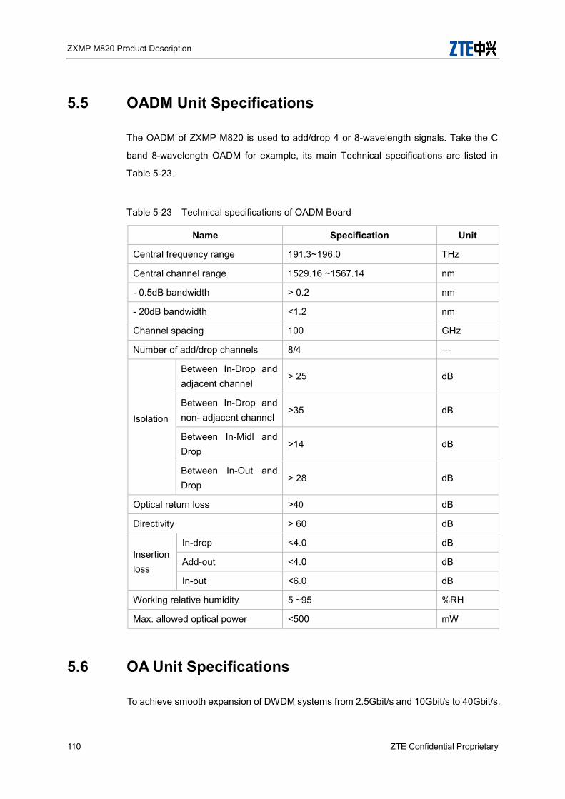
ZXMP M820 Product Description
110 ZTE Confidential Proprietary
5.5 OADM Unit Specifications
The OADM of ZXMP M820 is used to add/drop 4 or 8-wavelength signals. Take the C
band 8-wavelength OADM for example, its main Technical specifications are listed in
Table 5-23.
Table 5-23 Technical specifications of OADM Board
Name Specification Unit
Central frequency range 191.3~196.0 THz
Central channel range 1529.16 ~1567.14 nm
- 0.5dB bandwidth > 0.2 nm
- 20dB bandwidth <1.2 nm
Channel spacing 100 GHz
Number of add/drop channels 8/4 ---
Isolation
Between In-Drop and adjacent channel
> 25 dB
Between In-Drop and non- adjacent channel
>35 dB
Between In-Midl and Drop
>14 dB
Between In-Out and Drop
> 28 dB
Optical return loss >40 dB
Directivity > 60 dB
Insertion loss
In-drop <4.0 dB
Add-out <4.0 dB
In-out <6.0 dB
Working relative humidity 5 ~95 %RH
Max. allowed optical power <500 mW
5.6 OA Unit Specifications
To achieve smooth expansion of DWDM systems from 2.5Gbit/s and 10Gbit/s to 40Gbit/s,

ZXMP M820 Product Description
ZTE Confidential Proprietary 111
optical amplifiers used in the ZXWMM820 are compatible with both 2.5Gbit/s, 10Gbit/s
and 40Gbit/s systems.
5.6.1 Specifications of EOBA (Enhanced Optical Booster Amplifier) Board
40-channel C/L band optical booster amplifiers
As shown in Table 5-24, the single channel power is applicable to 40-channel
system.
Table 5-24 Technical specifications of 40-channel EOBA Board (C/L-band)
Item Unit Indices (40-channel system)
EOBA17/17 EOBA27/26 EOBA22/20 EOBA20/20 EOBA24/24
Working wavelength range
nm
1529~1561 (C band)
1570~1605 (L band)
1529~1561 (C band)
1570~1605
(L band)
1529~1561 (C band)
1570~1605 (L band)
1529~1561 (C band)
1570~1605 (L band)
1529~1561 (C band)
1570~1605(L band)
Total input power range
dBm -32 ~3 -32 ~2 -32 ~1 -32 ~3 -32 ~3
Input power range of the channel
dBm -32 ~-13 -32 ~-14 -32~ -15 -32 ~-13 -32 ~-13
Output power range of the channel
dBm -2~4 7~13 1~7 1~7 5~11
Total output power range
dBm -2~17 7~26 1~20 1~20 5~24
Max. total output power
dBm 17 26 20 20 24
Noise coefficient
dB <6 <6 <6 <6 <6
Polarization-related loss
dB <0.5 <0.5 <0.5 <0.5 <0.5
Pump leak at input
dBm <-30 <-30 <-30 <-30 <-30
Pump leak at dBm <-30 <-30 <-30 <-30 <-30

ZXMP M820 Product Description
112 ZTE Confidential Proprietary
Item Unit Indices (40-channel system)
EOBA17/17 EOBA27/26 EOBA22/20 EOBA20/20 EOBA24/24
output
Input return loss
dB >40 >40 >40 >40 >40
Output return loss
dB >40 >40 >40 >40 >40
Channel gain dB 17 27 22 20 24
Max. bearable reflectance at input
dB <-30 <-30 <-30 <-30 <-30
Max. bearable reflectance at output
dB <-30 <-30 <-30 <-30 <-30
Gain flatness dB ±1 ±1 ±1 ±1 ±1
Gain response time when channels are added or reduced (stable state)
ms <10 <10 <10 <10 <10
Polarization-mode dispersion
ps <0.5 <0.5 <0.5 <0.5 <0.5
80-channel C/L band optical booster amplifiers
As shown in Table 5-25, the single channel power is applicable to 80-channel
system.
Table 5-25 Technical specifications of 80-channel EOBA Board (C/L-band)
Item Unit Indices (80-channel system)
EOBA17/17 EOBA27/26 EOBA22/20 EOBA20/20 EOBA24/24
Working nm 1529~1561 1529~1561 1529~1561 1529~1561 1529~1561 (C

ZXMP M820 Product Description
ZTE Confidential Proprietary 113
Item Unit Indices (80-channel system)
EOBA17/17 EOBA27/26 EOBA22/20 EOBA20/20 EOBA24/24
wavelength range
(C band)
1570~1605 (L band)
(C band)
1570~1605
(L band)
(C band)
1570~1605 (L band)
(C band)
1570~1605 (L band)
band)
1570~1605(L band)
Total input power range
dBm -32 ~ 3 -32 ~2 -32 ~ 1 -32 ~ 3 -32 ~3
Input power range of the channel
dBm -32 ~ -16 -32 ~ -17 -32 ~ -18 -32 ~ -16 -32 ~ -16
Output power range of the channel
dBm -5~1 4~10 –2~4 –2~4 2~8
Total output power range
dBm -5~17 4~26 –2~20 –2~20 2~24
Max. total output power
dBm 17 26 20 20 24
Noise coefficient
dB <6 <6 <6 <6 <6
Polarization-related loss
dB <0.5 <0.5 <0.5 <0.5 <0.5
Pump leak at input
dBm <-30 <-30 <-30 <-30 <-30
Pump leak at output
dBm <-30 <-30 <-30 <-30 <-30
Input return loss
dB >40 >40 >40 >40 >40
Output return loss
dB >40 >40 >40 >40 >40
Channel gain dB 17 27 22 20 24
Max. bearable reflectance at input
dB <-30 <-30 <-30 <-30 <-30
Max. bearable reflectance at
dB <-30 <-30 <-30 <-30 <-30

ZXMP M820 Product Description
114 ZTE Confidential Proprietary
Item Unit Indices (80-channel system)
EOBA17/17 EOBA27/26 EOBA22/20 EOBA20/20 EOBA24/24
output
Gain flatness dB ±1 ±1 ±1 ±1 ±1
Gain response time when channels are added or reduced (stable state)
ms <10 <10 <10 <10 <10
Polarization-mode dispersion
ps <0.5 <0.5 <0.5 <0.5 <0.5
48-channel C band optical booster amplifiers
As shown in Table 5-26, the single channel power is applicable to 48-channel
system.
Table 5-26 Technical specifications of 48-channel EOBA Board (C-band)
Item Unit Indices (48-channel system)
EOBA17/17 EOBA23/21 EOBA26/24 EOBA28/26
Operating wavelength range
nm 1529-1568
(C-band)
1529-1568
(C-band)
1529-1568
(C-band)
1529-1568
(C-band)
Total input power range
dBm -32 ~3 -32 ~1 -32 ~1 -32 ~1
Channel input power range
dBm -32 ~-14 -32 to -19 -32 to -19 -32 to -19
Channel output power range
dBm –3~3 1~7 4~10 6~12
Total output power range
dBm –3~17 1~21 4~24 6~26
Maximum total output power
dBm 17 21 24 26
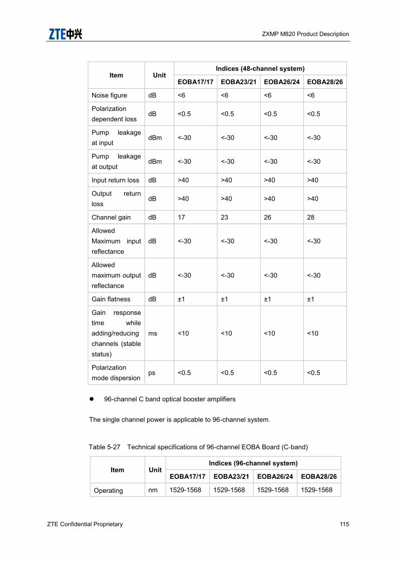
ZXMP M820 Product Description
ZTE Confidential Proprietary 115
Item Unit Indices (48-channel system)
EOBA17/17 EOBA23/21 EOBA26/24 EOBA28/26
Noise figure dB <6 <6 <6 <6
Polarization dependent loss
dB <0.5 <0.5 <0.5 <0.5
Pump leakage at input
dBm <-30 <-30 <-30 <-30
Pump leakage at output
dBm <-30 <-30 <-30 <-30
Input return loss dB >40 >40 >40 >40
Output return loss
dB >40 >40 >40 >40
Channel gain dB 17 23 26 28
Allowed Maximum input reflectance
dB <-30 <-30 <-30 <-30
Allowed maximum output reflectance
dB <-30 <-30 <-30 <-30
Gain flatness dB ±1 ±1 ±1 ±1
Gain response time while adding/reducing channels (stable status)
ms <10 <10 <10 <10
Polarization mode dispersion
ps <0.5 <0.5 <0.5 <0.5
96-channel C band optical booster amplifiers
The single channel power is applicable to 96-channel system.
Table 5-27 Technical specifications of 96-channel EOBA Board (C-band)
Item Unit Indices (96-channel system)
EOBA17/17 EOBA23/21 EOBA26/24 EOBA28/26
Operating nm 1529-1568 1529-1568 1529-1568 1529-1568

ZXMP M820 Product Description
116 ZTE Confidential Proprietary
Item Unit Indices (96-channel system)
EOBA17/17 EOBA23/21 EOBA26/24 EOBA28/26
wavelength range
(C-band) (C-band) (C-band) (C-band)
Total input power range
dBm -32 ~ 3 -32 ~ 1 -32 ~ 1 -32 ~ 1
Channel input power range
dBm -32 ~ -17 -32 ~ -19 -32 ~ -19 -32 ~ -19
Channel output power range
dBm -6 ~ 0 -2 ~ 4 1 ~ 7 3 ~ 9
Total output power range
dBm -6 ~ 17 -2 ~ 21 1 ~ 24 3 ~ 26
Maximum total output power
dBm 17 21 24 26
Noise figure dB <6 <6 <6 <6
Polarization dependent loss
dB <0.5 <0.5 <0.5 <0.5
Pump leakage at input
dBm <-30 <-30 <-30 <-30
Pump leakage at output
dBm <-30 <-30 <-30 <-30
Input return loss dB >40 >40 >40 >40
Output return loss
dB >40 >40 >40 >40
Channel gain dB 17 23 26 28
Allowed Maximum input reflectance
dB <-30 <-30 <-30 <-30
Allowed maximum output reflectance
dB <-30 <-30 <-30 <-30
Gain flatness dB ±1 ±1 ±1 ±1
Gain response time while adding/reducing
ms <10 <10 <10 <10

ZXMP M820 Product Description
ZTE Confidential Proprietary 117
Item Unit Indices (96-channel system)
EOBA17/17 EOBA23/21 EOBA26/24 EOBA28/26
channels (stable status)
Polarization mode dispersion
ps <0.5 <0.5 <0.5 <0.5
5.6.2 Specifications of EOLA (Enhanced Optical Line Amplifier) Board
40/80-channel C/L band optical line amplifiers
Technical specifications of the 40/80-channel C/L band EOLA are listed in Table
5-28.
Table 5-28 Technical specifications of 40/80-channel EOLA Board (C/L-band)
Item Unit Indices (40-channel system) Indices (80-channel system)
EOLA22/20 EOLA27/20 EOLA32/20 EOLA22/20 EOLA27/20 EOLA32/20
Working wavelength range
nm
1529~1561 (C band)
1570~1605 (L band)
1529~1561 (C band)
1570~1605 (L band)
1529~1561 (C band)
1570~1605 (L band)
1529~1561 (C band)
1570~1605 (L band)
1529~1561 (C band)
1570~1605 (L band)
1529~1561 (C band)
1570~1605 (L band)
Total input power range
dBm -35 ~ 1 -35 ~ -4 -35 ~ -9 -35 ~ 1 -35 ~ -4 -35 ~ -9
Input power range of the channel
dBm -35 ~ -15 -35 ~ -20 -35 ~ -25 -35 ~ -18 -35 ~ -23 -35 ~ -28
Output power range of the channel
dBm 1~7 1~7 1~7 -2~4 -2~4 -2~4
Total output power range
dBm 1~20 1~20 1~20 -2~20 -2~20 -2~20
Max. total output power
dBm 20 20 20 20 20 20
Noise coefficient
dB <6 <6 <6 <6 <6 <6

ZXMP M820 Product Description
118 ZTE Confidential Proprietary
Item Unit Indices (40-channel system) Indices (80-channel system)
EOLA22/20 EOLA27/20 EOLA32/20 EOLA22/20 EOLA27/20 EOLA32/20
Polarization-related loss
dB <0.5 <0.5 <0.5 <0.5 <0.5 <0.5
Pump leak at input
dBm <-30 <-30 <-30 <-30 <-30 <-30
Pump leak at output
dBm <-30 <-30 <-30 <-30 <-30 <-30
Input return loss
dB >40 >40 >40 >40 >40 >40
Output return loss
dB >40 >40 >40 >40 >40 >40
Channel gain dB 22 27 32 22 27 32
Max. bearable reflectance at input
dB <-30 <-30 <-30 <-30 <-30 <-30
Max. bearable reflectance at output
dB <-30 <-30 <-30 <-30 <-30 <-30
Gain flatness dB ±1 ±1 ±1 ±1 ±1 ±1
Gain response time when channels are added or reduced (stable state)
Ms <10 <10 <10 <10 <10 <10
Polarization-mode dispersion
Ps <0.5 <0.5 <0.5 <0.5 <0.5 <0.5
5.6.3 Specifications of EOPA (Optical preamplifier) Board
40-channel C/L band optical preamplifiers
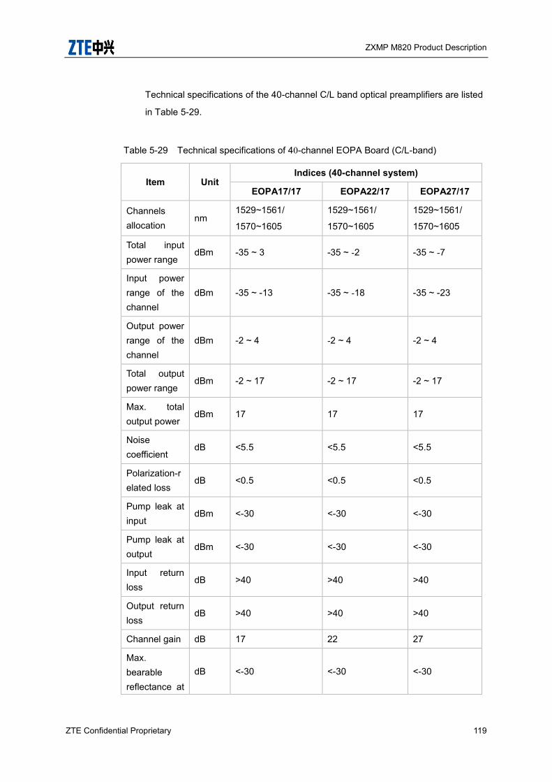
ZXMP M820 Product Description
ZTE Confidential Proprietary 119
Technical specifications of the 40-channel C/L band optical preamplifiers are listed
in Table 5-29.
Table 5-29 Technical specifications of 40-channel EOPA Board (C/L-band)
Item Unit Indices (40-channel system)
EOPA17/17 EOPA22/17 EOPA27/17
Channels allocation
nm 1529~1561/
1570~1605
1529~1561/
1570~1605
1529~1561/
1570~1605
Total input power range
dBm -35 ~ 3 -35 ~ -2 -35 ~ -7
Input power range of the channel
dBm -35 ~ -13 -35 ~ -18 -35 ~ -23
Output power range of the channel
dBm -2 ~ 4 -2 ~ 4 -2 ~ 4
Total output power range
dBm -2 ~ 17 -2 ~ 17 -2 ~ 17
Max. total output power
dBm 17 17 17
Noise coefficient
dB <5.5 <5.5 <5.5
Polarization-related loss
dB <0.5 <0.5 <0.5
Pump leak at input
dBm <-30 <-30 <-30
Pump leak at output
dBm <-30 <-30 <-30
Input return loss
dB >40 >40 >40
Output return loss
dB >40 >40 >40
Channel gain dB 17 22 27
Max. bearable reflectance at
dB <-30 <-30 <-30

ZXMP M820 Product Description
120 ZTE Confidential Proprietary
Item Unit Indices (40-channel system)
EOPA17/17 EOPA22/17 EOPA27/17
input
Max. bearable reflectance at output
dB <-30 <-30 <-30
Gain flatness
dB ±1 ±1 ±1
Gain response time when channels are added or reduced (stable state)
ms <10 <10 <10
Polarization-mode dispersion
ps <0.5 <0.5 <0.5
80-channel C/L band optical preamplifiers
Technical specifications of the 80-channel C/L band optical preamplifiers are listed
in Table 5-30.
Table 5-30 Technical specifications of 40-channel EOPA Board (C/L-band)
Item Unit Indices (80-channel system)
EOPA17/17 EOPA22/17 EOPA27/17
Channels allocation
nm 1529~1561/
1570~1605
1529~1561/
1570~1605
1529~1561/
1570~1605
Total input power range
dBm -35 ~ 3 -35 ~ -2 -35 ~ -7
Input power range of the channel
dBm -35 ~ -16 -35 ~ -21 -35 ~ -26
Output power range of the
dBm -5 ~ 1 -5 ~ 1 -5 ~ 1

ZXMP M820 Product Description
ZTE Confidential Proprietary 121
Item Unit Indices (80-channel system)
EOPA17/17 EOPA22/17 EOPA27/17
channel
Total output power range
dBm -5 ~ 17 -5 ~ 17 -5 ~ 17
Max. total output power
dBm 17 17 17
Noise coefficient
dB <5.5 <5.5 <5.5
Polarization-related loss
dB <0.5 <0.5 <0.5
Pump leak at input
dBm <-30 <-30 <-30
Pump leak at output
dBm <-30 <-30 <-30
Input return loss
dB >40 >40 >40
Output return loss
dB >40 >40 >40
Channel gain dB 17 22 27
Max. bearable reflectance at input
dB <-30 <-30 <-30
Max. bearable reflectance at output
dB <-30 <-30 <-30
Gain flatness
dB ±1 ±1 ±1
Gain response time when channels are added or reduced (stable state)
ms <10 <10 <10

ZXMP M820 Product Description
122 ZTE Confidential Proprietary
Item Unit Indices (80-channel system)
EOPA17/17 EOPA22/17 EOPA27/17
Polarization-mode dispersion
ps <0.5 <0.5 <0.5
48-channel C band optical preamplifiers
Technical specifications of the 48-channel C band optical preamplifiers are listed in
Table 5-31.
Table 5-31 Technical specifications of 48-channel EOPA Board (C-band)
Item Unit Indices (48-channel system)
EOPA17/17 EOPA22/17 EOPA27/17
Operating wavelength range
nm 1529-1568 (C-band)
1529-1568 (C-band)
1529-1568 (C-band)
Total input power range
dBm -35 ~ 3 -35 ~ -2 -35 ~ -7
Channel input power range
dBm -35 ~ -14 -35 ~ -19 -35 ~ -24
Channel output power range
dBm -3 ~ 3 -3 ~ 3 -3 ~ 3
Total output power range
dBm -3 ~ 17 -3 ~ 17 -3 ~ 17
Maximum total output power
dBm 17 17 17
Noise figure dB <5.5 <5.5 <5.5
Polarization dependent loss
dB <0.5 <0.5 <0.5
Pump leakage at input
dBm <-30 <-30 <-30
Pump leakage at output
dBm <-30 <-30 <-30
Input return loss dB >40 >40 >40
Output return loss dB >40 >40 >40

ZXMP M820 Product Description
ZTE Confidential Proprietary 123
Item Unit Indices (48-channel system)
EOPA17/17 EOPA22/17 EOPA27/17
Channel gain dB 17 22 27
Allowed maximum input reflectance
dB <-30 <-30 <-30
Allowed maximum output reflectance
dB <-30 <-30 <-30
Gain flatness dB ±1 ±1 ±1
Gain response time while adding/ reducing channels (stable status)
ms <10 <10 <10
Polarization mode dispersion
ps <0.5 <0.5 <0.5
96-channel C band optical preamplifiers
Technical specifications of the 96-channel C band optical preamplifiers are listed in
Table 5-32.
Table 5-32 Technical specifications of 96-channel EOPA Board (C-band)
Item Unit Indices (96-channel system)
EOPA17/17 EOPA22/17 EOPA27/17
Operating wavelength range
nm 1529-1568 (C-band)
1529-1568 (C-band)
1529-1568 (C-band)
Total input power range
dBm -35 ~ 3 -35 ~ -2 -35 ~ -7
Channel input power range
dBm -35 ~ -17 -35 ~ -22 -35 ~ -27
Channel output power range
dBm -6 ~ 0 -6 ~ 0 -6 ~ 0
Total output power range
dBm -6 ~ 17 -6 ~ 17 -6 ~ 17
Maximum total output power
dBm 17 17 17
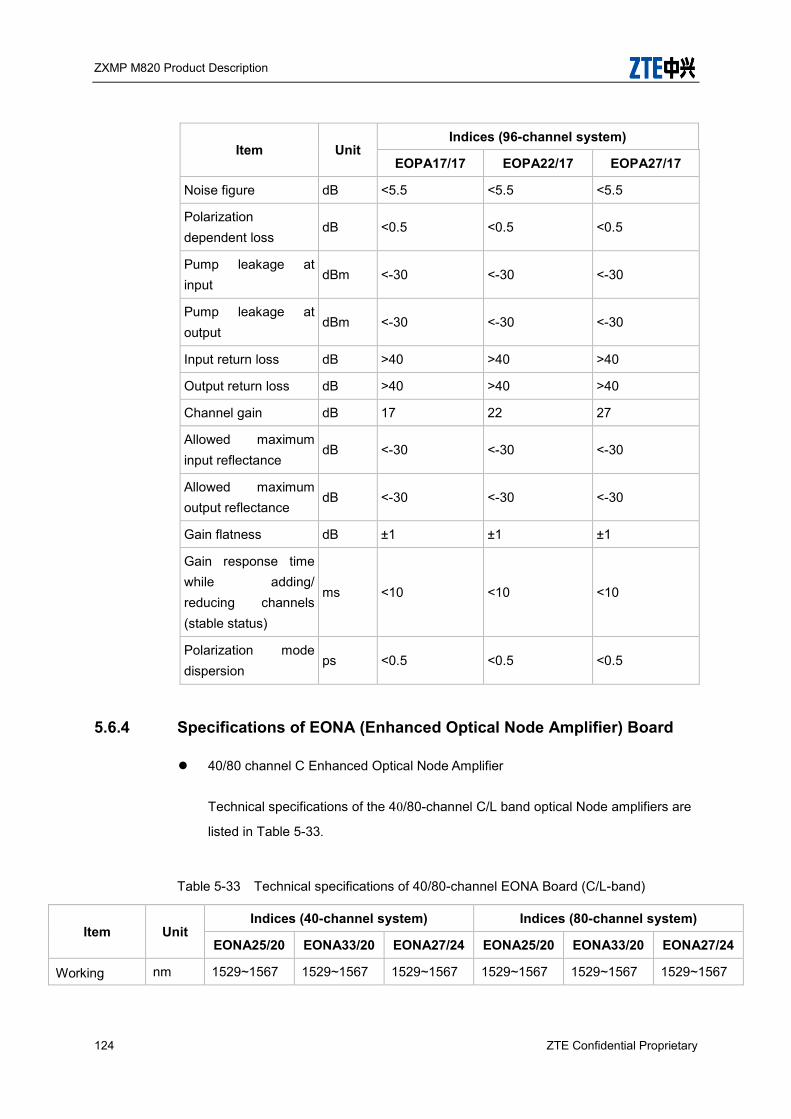
ZXMP M820 Product Description
124 ZTE Confidential Proprietary
Item Unit Indices (96-channel system)
EOPA17/17 EOPA22/17 EOPA27/17
Noise figure dB <5.5 <5.5 <5.5
Polarization dependent loss
dB <0.5 <0.5 <0.5
Pump leakage at input
dBm <-30 <-30 <-30
Pump leakage at output
dBm <-30 <-30 <-30
Input return loss dB >40 >40 >40
Output return loss dB >40 >40 >40
Channel gain dB 17 22 27
Allowed maximum input reflectance
dB <-30 <-30 <-30
Allowed maximum output reflectance
dB <-30 <-30 <-30
Gain flatness dB ±1 ±1 ±1
Gain response time while adding/ reducing channels (stable status)
ms <10 <10 <10
Polarization mode dispersion
ps <0.5 <0.5 <0.5
5.6.4 Specifications of EONA (Enhanced Optical Node Amplifier) Board
40/80 channel C Enhanced Optical Node Amplifier
Technical specifications of the 40/80-channel C/L band optical Node amplifiers are
listed in Table 5-33.
Table 5-33 Technical specifications of 40/80-channel EONA Board (C/L-band)
Item Unit Indices (40-channel system) Indices (80-channel system)
EONA25/20 EONA33/20 EONA27/24 EONA25/20 EONA33/20 EONA27/24
Working nm 1529~1567 1529~1567 1529~1567 1529~1567 1529~1567 1529~1567

ZXMP M820 Product Description
ZTE Confidential Proprietary 125
Item Unit Indices (40-channel system) Indices (80-channel system)
EONA25/20 EONA33/20 EONA27/24 EONA25/20 EONA33/20 EONA27/24
wavelength range
(C-band)
1570~1605
(L-band)
(C-band)
1570~1605
(L-band)
(C-band)
1570~1605
(L-band)
(C-band)
1570~1605
(L-band)
(C-band)
1570~1605
(L-band)
(C-band)
1570~1605
(L-band)
Total input power range
dBm -35 ~ -2 -35 ~ -10 -35 ~ 0 -35 ~ -2 -35 ~ -10 -35 ~ 0
Input power range of the channel
dBm -35 ~ -18 -35 ~ -26 -35 ~ -16 -35 ~ -21 -35 ~ -29 -35 ~ -19
Output power range of the channel
dBm 1 ~ 7 1 ~ 7 5 ~ 11 -2 ~ 4 -2 ~ 4 2 ~ 8
Total output power range
dBm 1 ~ 20 1 ~ 20 5 ~ 24 -2 ~ 20 -2 ~ 20 2 ~ 24
Max. total output power
dBm 20 20 24 20 20 24
Noise coefficient
dB
20~22: 8.0
22~25: 7.0
25~30: 6.5
28~30: 6.5
30~38: 6.0
22~24: 8.5
24~27: 7.5
27~32: 6.5
20~22: 8.0
22~25: 7.0
25~30: 6.5
28~30: 6.5
30~38: 6.0
22~24: 8.5
24~27: 7.5
27~32: 6.5
Polarization-related loss
dB <0.5 <0.5 <0.5 <0.5 <0.5 <0.5
Pump leak at input
dBm <-30 <-30 <-30 <-30 <-30 <-30
Pump leak at output
dBm <-30 <-30 <-30 <-30 <-30 <-30
Input return loss
dB >40 >40 >40 >40 >40 >40
Output return loss
dB >40 >40 >40 >40 >40 >40
Channel gain dB 25 33 27 25 33 27
Max. bearable reflectance at input
dB <-30 <-30 <-30 <-30 <-30 <-30
Max. dB <-30 <-30 <-30 <-30 <-30 <-30

ZXMP M820 Product Description
126 ZTE Confidential Proprietary
Item Unit Indices (40-channel system) Indices (80-channel system)
EONA25/20 EONA33/20 EONA27/24 EONA25/20 EONA33/20 EONA27/24
bearable reflectance at output
Gain flatness dB ±1 ±1 ±1 ±1 ±1 ±1
Gain response time when channels are added or reduced (stable state)
ms <10 <10 <10 <10 <10 <10
Polarization-mode dispersion
ps <0.5 <0.5 <0.5 <0.5 <0.5 <0.5
48/96-channel C Enhanced Optical Node Amplifier
Technical specifications of the 48/96-channel C band optical Node amplifiers are
listed in Table 5-34.
Table 5-34 Technical specifications of 48/96-channel EONA Board (C/L-band)
Item Unit Indices (48-channel system)) Indices (96-channel system))
EONA25/21 EONA33/21 EONA27/24 EONA25/21 EONA33/21 EONA27/24
Operating wavelength range
nm 1529-1568 (C-band)
1529-1568 (C-band)
1529-1568 (C-band)
1529-1568 (C-band)
1529-1568 (C-band)
1529-1568 (C-band)
Total input power range
dBm -35 ~ -1 -35 ~ -9 -35 ~ 0 -35 ~ -1 -35 ~ -9 -35 ~ 0
Channel input power range
dBm -35 ~ -18 -35 ~ -26 -35 ~ -17 -35 ~ -21 -35 ~ -29 -35 ~ -20
Channel output power range
dBm 1 ~ 7 1 ~ 7 4 ~ 10 -2 ~ 4 -2 ~ 4 1 ~ 7
Total output power range
dBm 1 ~ 21 1 ~ 21 4 ~ 24 -2 ~ 21 -2 ~ 21 1 ~ 24
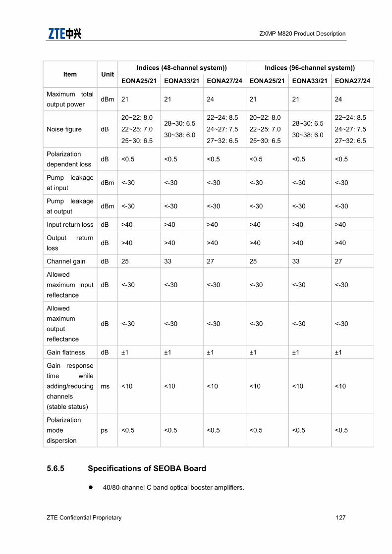
ZXMP M820 Product Description
ZTE Confidential Proprietary 127
Item Unit Indices (48-channel system)) Indices (96-channel system))
EONA25/21 EONA33/21 EONA27/24 EONA25/21 EONA33/21 EONA27/24
Maximum total output power
dBm 21 21 24 21 21 24
Noise figure dB
20~22: 8.0
22~25: 7.0
25~30: 6.5
28~30: 6.5
30~38: 6.0
22~24: 8.5
24~27: 7.5
27~32: 6.5
20~22: 8.0
22~25: 7.0
25~30: 6.5
28~30: 6.5
30~38: 6.0
22~24: 8.5
24~27: 7.5
27~32: 6.5
Polarization dependent loss
dB <0.5 <0.5 <0.5 <0.5 <0.5 <0.5
Pump leakage at input
dBm <-30 <-30 <-30 <-30 <-30 <-30
Pump leakage at output
dBm <-30 <-30 <-30 <-30 <-30 <-30
Input return loss dB >40 >40 >40 >40 >40 >40
Output return loss
dB >40 >40 >40 >40 >40 >40
Channel gain dB 25 33 27 25 33 27
Allowed maximum input reflectance
dB <-30 <-30 <-30 <-30 <-30 <-30
Allowed maximum output reflectance
dB <-30 <-30 <-30 <-30 <-30 <-30
Gain flatness dB ±1 ±1 ±1 ±1 ±1 ±1
Gain response time while adding/reducing channels (stable status)
ms <10 <10 <10 <10 <10 <10
Polarization mode dispersion
ps <0.5 <0.5 <0.5 <0.5 <0.5 <0.5
5.6.5 Specifications of SEOBA Board
40/80-channel C band optical booster amplifiers.
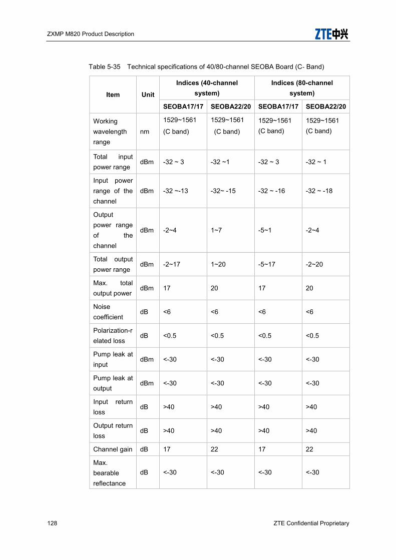
ZXMP M820 Product Description
128 ZTE Confidential Proprietary
Table 5-35 Technical specifications of 40/80-channel SEOBA Board (C- Band)
Item Unit
Indices (40-channel system)
Indices (80-channel system)
SEOBA17/17 SEOBA22/20 SEOBA17/17 SEOBA22/20
Working wavelength range
nm
1529~1561
(C band)
1529~1561
(C band)
1529~1561 (C band)
1529~1561 (C band)
Total input power range
dBm -32 ~ 3 -32 ~1 -32 ~ 3 -32 ~ 1
Input power range of the channel
dBm -32 ~-13 -32~ -15 -32 ~ -16 -32 ~ -18
Output power range of the channel
dBm -2~4 1~7 -5~1 -2~4
Total output power range
dBm -2~17 1~20 -5~17 -2~20
Max. total output power
dBm 17 20 17 20
Noise coefficient
dB <6 <6 <6 <6
Polarization-related loss
dB <0.5 <0.5 <0.5 <0.5
Pump leak at input
dBm <-30 <-30 <-30 <-30
Pump leak at output
dBm <-30 <-30 <-30 <-30
Input return loss
dB >40 >40 >40 >40
Output return loss
dB >40 >40 >40 >40
Channel gain dB 17 22 17 22
Max. bearable reflectance
dB <-30 <-30 <-30 <-30
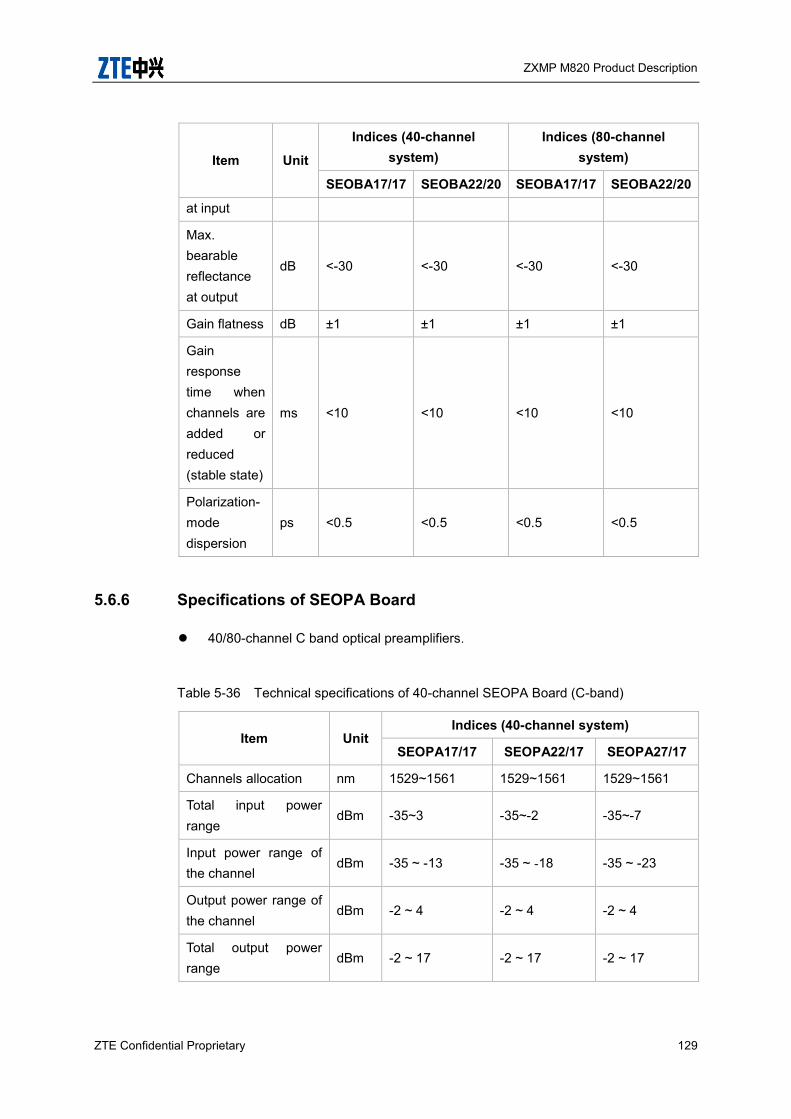
ZXMP M820 Product Description
ZTE Confidential Proprietary 129
Item Unit
Indices (40-channel system)
Indices (80-channel system)
SEOBA17/17 SEOBA22/20 SEOBA17/17 SEOBA22/20
at input
Max. bearable reflectance at output
dB <-30 <-30 <-30 <-30
Gain flatness dB ±1 ±1 ±1 ±1
Gain response time when channels are added or reduced (stable state)
ms <10 <10 <10 <10
Polarization-mode dispersion
ps <0.5 <0.5 <0.5 <0.5
5.6.6 Specifications of SEOPA Board
40/80-channel C band optical preamplifiers.
Table 5-36 Technical specifications of 40-channel SEOPA Board (C-band)
Item Unit Indices (40-channel system)
SEOPA17/17 SEOPA22/17 SEOPA27/17
Channels allocation nm 1529~1561 1529~1561 1529~1561
Total input power range
dBm -35~3 -35~-2 -35~-7
Input power range of the channel
dBm -35 ~ -13 -35 ~ -18 -35 ~ -23
Output power range of the channel
dBm -2 ~ 4 -2 ~ 4 -2 ~ 4
Total output power range
dBm -2 ~ 17 -2 ~ 17 -2 ~ 17

ZXMP M820 Product Description
130 ZTE Confidential Proprietary
Item Unit Indices (40-channel system)
SEOPA17/17 SEOPA22/17 SEOPA27/17
Max. total output power
dBm 17 17 17
Noise coefficient dB <5.5 <5.5 <5.5
Polarization-related loss
dB <0.5 <0.5 <0.5
Pump leak at input dBm <-30 <-30 <-30
Pump leak at output dBm <-30 <-30 <-30
Input return loss dB >40 >40 >40
Output return loss dB >40 >40 >40
Channel gain dB 17 22 27
Max. bearable reflectance at input
dB <-30 <-30 <-30
Max. bearable reflectance at output
dB <-30 <-30 <-30
Gain flatness dB ±1 ±1 ±1
Gain response time when channels are added or reduced (stable state)
ms <10 <10 <10
Polarization-mode dispersion
ps <0.5 <0.5 <0.5
Table 5-37 Technical specifications of 80-channel SEOPA Board (C-band)
Item Unit Indices (80-channel system)
SEOPA17/17 SEOPA22/17 SEOPA27/17
Channels allocation nm 1529~1561 1529~1561 1529~1561
Total input power range
dBm -35 ~ 3 -35 ~ -2 -35 ~ -7
Input power range of the channel
dBm -35 ~ -16 -35 ~ -21 -35 ~ -26
Output power range of the channel
dBm -5 ~ 1 -5 ~ 1 -5 ~ 1
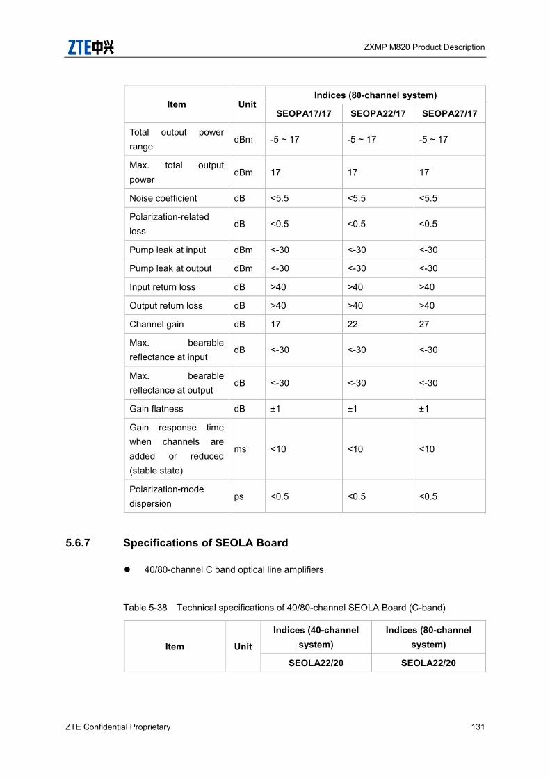
ZXMP M820 Product Description
ZTE Confidential Proprietary 131
Item Unit Indices (80-channel system)
SEOPA17/17 SEOPA22/17 SEOPA27/17
Total output power range
dBm -5 ~ 17 -5 ~ 17 -5 ~ 17
Max. total output power
dBm 17 17 17
Noise coefficient dB <5.5 <5.5 <5.5
Polarization-related loss
dB <0.5 <0.5 <0.5
Pump leak at input dBm <-30 <-30 <-30
Pump leak at output dBm <-30 <-30 <-30
Input return loss dB >40 >40 >40
Output return loss dB >40 >40 >40
Channel gain dB 17 22 27
Max. bearable reflectance at input
dB <-30 <-30 <-30
Max. bearable reflectance at output
dB <-30 <-30 <-30
Gain flatness dB ±1 ±1 ±1
Gain response time when channels are added or reduced (stable state)
ms <10 <10 <10
Polarization-mode dispersion
ps <0.5 <0.5 <0.5
5.6.7 Specifications of SEOLA Board
40/80-channel C band optical line amplifiers.
Table 5-38 Technical specifications of 40/80-channel SEOLA Board (C-band)
Item Unit
Indices (40-channel system)
Indices (80-channel system)
SEOLA22/20 SEOLA22/20

ZXMP M820 Product Description
132 ZTE Confidential Proprietary
Item Unit
Indices (40-channel system)
Indices (80-channel system)
SEOLA22/20 SEOLA22/20
Working wavelength range
nm 1529~1561 (C band) 1529~1561 (C band)
Total input power range
dBm -35 ~ 1 -35 ~ 1
Input power range of the channel
dBm -35 ~ -15 -35 ~ -18
Output power range of the channel
dBm 1-7 -2~4
Total output power range
dBm 1~20 -2~20
Max. total output power
dBm 20 20
Noise coefficient dB <6 <6
Polarization-related loss
dB <0.5 <0.5
Pump leak at input dBm <-30 <-30
Pump leak at output dBm <-30 <-30
Input return loss dB >40 >40
Output return loss dB >40 >40
Channel gain dB 22 22
Max. bearable reflectance at input
dB >30 >30
Max. bearable reflectance at output
dB >30 >30
Gain flatness dB ±1 ±1
Gain response time when channels are added or reduced (stable state)
Ms <10 <10
Polarization-mode dispersion
Ps <0.5 <0.5
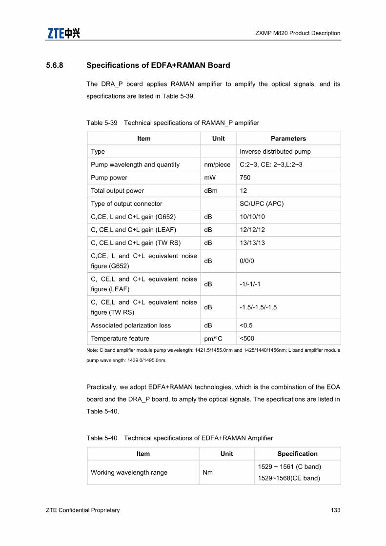
ZXMP M820 Product Description
ZTE Confidential Proprietary 133
5.6.8 Specifications of EDFA+RAMAN Board
The DRA_P board applies RAMAN amplifier to amplify the optical signals, and its
specifications are listed in Table 5-39.
Table 5-39 Technical specifications of RAMAN_P amplifier
Item Unit Parameters
Type Inverse distributed pump
Pump wavelength and quantity nm/piece C:2~3, CE: 2~3,L:2~3
Pump power mW 750
Total output power dBm 12
Type of output connector SC/UPC (APC)
C,CE, L and C+L gain (G652) dB 10/10/10
C, CE,L and C+L gain (LEAF) dB 12/12/12
C, CE,L and C+L gain (TW RS) dB 13/13/13
C,CE, L and C+L equivalent noise figure (G652)
dB 0/0/0
C, CE,L and C+L equivalent noise figure (LEAF)
dB -1/-1/-1
C, CE,L and C+L equivalent noise figure (TW RS)
dB -1.5/-1.5/-1.5
Associated polarization loss dB <0.5
Temperature feature pm/C <500
Note: C band amplifier module pump wavelength: 1421.5/1455.0nm and 1425/1440/1456nm; L band amplifier module
pump wavelength: 1439.0/1495.0nm.
Practically, we adopt EDFA+RAMAN technologies, which is the combination of the EOA
board and the DRA_P board, to amply the optical signals. The specifications are listed in
Table 5-40.
Table 5-40 Technical specifications of EDFA+RAMAN Amplifier
Item Unit Specification
Working wavelength range Nm 1529 ~ 1561 (C band)
1529~1568(CE band)

ZXMP M820 Product Description
134 ZTE Confidential Proprietary
Item Unit Specification
1570 ~ 1605 (L band)
Max. total output power dBm > 20
Noise coefficient dB < 3
Polarization-related gain dB < 0.5
Input reflectance dB >40
Output reflectance dB >40
Max. bearable reflectance at input dB <-30
Max. bearable reflectance at output dB <-30
Gain flatness dB 1
Gain response time when channels are added or reduced (stable state)
Ms < 10
Polarization-mode dispersion Ps < 0.5
The DRA_B board applies RAMAN amplifier to amplify the optical signals, and its
specifications are listed in Table 5-41.
Table 5-41 Performance Parameters of RAMAN_B amplifier
Item Unit Parameters
Type Inverse distributed pump
Pump wavelength nm
1529 ~ 1561 (C band)
1529~1568(CE band)
1570 ~ 1605 (L band)
Pump power mW 850
Total output power dBm 12
Band gain(G.652) dB 1-6
Noise figure dB <1
Polarization dependent loss dB <0.2
Input return loss dB >45
Output return loss dB >45
Gain flatness dB <4
Polarization mode dispersion ps <0.5

ZXMP M820 Product Description
ZTE Confidential Proprietary 135
Item Unit Parameters
Insertion loss dB <1.5
5.6.9 Specifications of RPOA Board
RPOA amplifier technical specifications are listed in Table 5-42.
Table 5-42 Technical specifications of RPOA amplifier
Item RPOA with GFF sub-system RPOA without GFF sub-system
Working wavelength range
1529~1561nm 1546~1561nm
Noise coefficient
<7dB <7dB
Gain >17dB >17dB
Gain flatness
<2dB <2dB
Total input power range
-44~-18dBm -44~-18dBm
Total output power range
-30~2dBm -34~8dBm
Working temperature range
-40~65°C (RGU),
-10~60°C(RPU)
-40~65°C (RGU)
-10~60°C(RPU)
Storage temperature range
-40~85°C -40~85°C
Notes: RPOA subsystems without Gain Flatness Filter (GFF) meet the requirements of systems with capacity below 16
wavelengths, while RPOA subsystems with GFF meet the requirements of systems with capacity of 40 wavelengths.
5.6.10 Specifications of LAC Board
Technical specifications of LAC board are listed in Table 5-43.

ZXMP M820 Product Description
136 ZTE Confidential Proprietary
Table 5-43 Technical Specifications of LAC Board
Item Unit Specification
Application wavelength range nm
1529~1561(C band)
1529~1568(CE band)
1570~1605(L band)
Input power detection range dBm -39 to +20
Output power detection range dBm -40 to +18
Optical power detection Precision dB ≤±0.5
Attenuation adjustment precision dB ≤±0.5
Attenuation adjustment step length dB ≤±0.2
Attenuation adjustment range dB ≥20
Attenuation adjustment rate dB ≤10
5.7 OTU Unit Specifications
This section describes the specifications of transponder boards, including the
transponders of 2.5Gbit/s, 10Gbit/s, 40Gbit/s and 100Gbit/s.
5.7.1 Specifications of 2.5Gbit/s Board
Client-side: Transmitting part of receiving end and receiving part of transmitting end.
Line-side: Receiving part of receiving end, transmitting part of transmitting end and
transmitting/receiving part of regenerator.
Technical specifications of 2.5Gbit/s board at Client-Side and Line-Side are listed in
Table 5-44 and Table 5-45.
Table 5-44 Technical specifications of 2.5Gbit/s Board at Client-side
Item Unit Parameter
Parameters of optical receive port at client side (S point)
Type of Receiver --- PIN
Receiving sensitivity (BER10-12) dBm -18
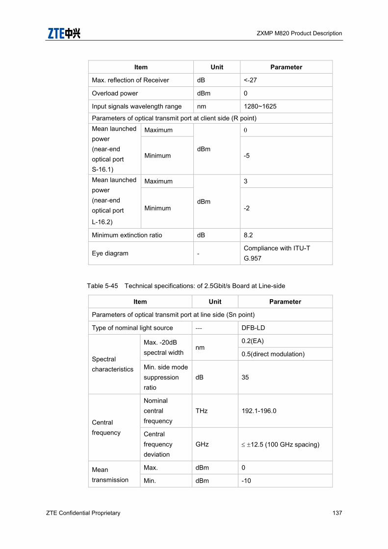
ZXMP M820 Product Description
ZTE Confidential Proprietary 137
Item Unit Parameter
Max. reflection of Receiver dB <-27
Overload power dBm 0
Input signals wavelength range nm 1280~1625
Parameters of optical transmit port at client side (R point) Mean launched power (near-end optical port S-16.1)
Maximum
dBm
0
Minimum -5
Mean launched power (near-end optical port
L-16.2)
Maximum
dBm
3
Minimum -2
Minimum extinction ratio dB 8.2
Eye diagram - Compliance with ITU-T G.957
Table 5-45 Technical specifications: of 2.5Gbit/s Board at Line-side
Item Unit Parameter
Parameters of optical transmit port at line side (Sn point)
Type of nominal light source --- DFB-LD
Spectral characteristics
Max. -20dB spectral width
nm 0.2(EA)
0.5(direct modulation)
Min. side mode suppression ratio
dB 35
Central frequency
Nominal central frequency
THz 192.1-196.0
Central frequency deviation
GHz 12.5 (100 GHz spacing)
Mean transmission
Max. dBm 0
Min. dBm -10
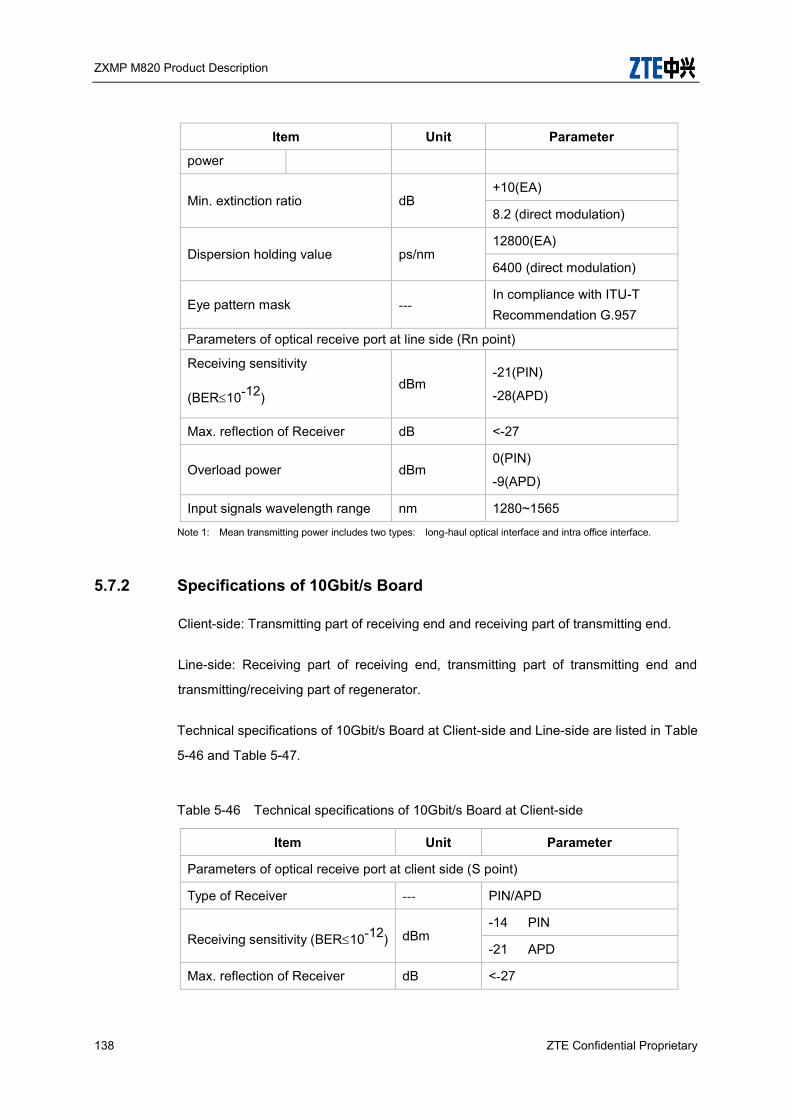
ZXMP M820 Product Description
138 ZTE Confidential Proprietary
Item Unit Parameter
power
Min. extinction ratio dB +10(EA)
8.2 (direct modulation)
Dispersion holding value ps/nm 12800(EA)
6400 (direct modulation)
Eye pattern mask --- In compliance with ITU-T Recommendation G.957
Parameters of optical receive port at line side (Rn point)
Receiving sensitivity
(BER10-12) dBm
-21(PIN)
-28(APD)
Max. reflection of Receiver dB <-27
Overload power dBm 0(PIN)
-9(APD)
Input signals wavelength range nm 1280~1565
Note 1: Mean transmitting power includes two types: long-haul optical interface and intra office interface.
5.7.2 Specifications of 10Gbit/s Board
Client-side: Transmitting part of receiving end and receiving part of transmitting end.
Line-side: Receiving part of receiving end, transmitting part of transmitting end and
transmitting/receiving part of regenerator.
Technical specifications of 10Gbit/s Board at Client-side and Line-side are listed in Table
5-46 and Table 5-47.
Table 5-46 Technical specifications of 10Gbit/s Board at Client-side
Item Unit Parameter
Parameters of optical receive port at client side (S point)
Type of Receiver --- PIN/APD
Receiving sensitivity (BER10-12) dBm -14 PIN
-21 APD
Max. reflection of Receiver dB <-27
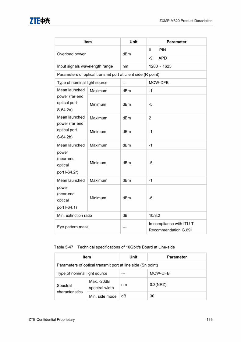
ZXMP M820 Product Description
ZTE Confidential Proprietary 139
Item Unit Parameter
Overload power dBm 0 PIN
-9 APD
Input signals wavelength range nm 1280 ~ 1625
Parameters of optical transmit port at client side (R point)
Type of nominal light source --- MQW-DFB
Mean launched power (far-end optical port
S-64.2a)
Maximum dBm -1
Minimum dBm -5
Mean launched power (far-end optical port
S-64.2b)
Maximum dBm 2
Minimum dBm -1
Mean launched
power (near-end optical
port I-64.2r)
Maximum dBm -1
Minimum dBm -5
Mean launched
power (near-end optical
port I-64.1)
Maximum dBm -1
Minimum dBm -6
Min. extinction ratio dB 10/8.2
Eye pattern mask --- In compliance with ITU-T Recommendation G.691
Table 5-47 Technical specifications of 10Gbit/s Board at Line-side
Item Unit Parameter
Parameters of optical transmit port at line side (Sn point)
Type of nominal light source --- MQW-DFB
Spectral characteristics
Max. -20dB spectral width
nm 0.3(NRZ)
Min. side mode dB 30

ZXMP M820 Product Description
140 ZTE Confidential Proprietary
Item Unit Parameter
suppression ratio
Central frequency
Nominal central frequency
THz ITU.T .694.1 compliant
Central frequency deviation (EOL)
GHz ≤12.5 (spacing: 100 GHz)
≤5 (spacing: 50 GHz)
Central frequency deviation (BOL)
GHz ≤10 (spacing: 100 GHz)
≤3(spacing: 50 GHz)
Mean transmission power
Max. dBm +1(NRZ)
-2(ERZ)
Min. dBm -3(NRZ)
-5(ERZ)
Chirp modulus --- 0.3 ~ 0.7
Min. extinction ratio dB +8.2
Dispersion holding value ps/nm -300~800(NRZ)
400(ERZ)
Eye pattern mask ---
In compliance with ITU-T Recommendation G.691(STM-64)
In compliance with ITU-T Recommendation G.959.1(OTU2)
Parameters of optical receive port at line side (Rn point)
Receiving sensitivity
(BER10-12) dBm
PIN -14 (STM-64)
APD -21 (STM-64)
Max. reflection of Receiver dB <–27
Overload power dBm 0 (PIN)
-9 (APD)

ZXMP M820 Product Description
ZTE Confidential Proprietary 141
Item Unit Parameter
Input signals wavelength range nm 1280 ~ 1565
5.7.3 Specifications of 40Gbit/s Board
Client-side: Transmitting part of receiving end and receiving part of transmitting end.
Line-side: Receiving part of receiving end, transmitting part of transmitting end and
transmitting/receiving part of regenerator.
Technical specifications of 40Gbit/s Board at Client-side and Line-side are listed in Table
5-48 and Table 5-49.
Table 5-48 Technical specifications of 40Gbit/s Board at Client-side
Item Unit Specification
Bit rate (optical modulation mode) Gbps 39.813 (NRZ),
43.018
39.813 (NRZ),
43.018
Optical interface category --- VSR2000-3R2 P1I13D1 and
1I13D1F
Goal distance km 2 10
Parameters of optical receive port at client side (S point)
Frequency range nm 1280-1625 1280-1625
Sensitivity (BER=10–12) dBm -6 -7
Overload power(BER=10–12) dBm +3 +4
Receiver reflectance dB <-27 <-27
Parameters of optical transmit port at client side (R point)
Frequency range --- 1280-1625 1307–1317
Mean launched power
Maximum dBm
+3 +4
Minimum 0 0
Minimum side mode compression ratio(SMCR)
dB 35 35
Minimum extinction ratio dB 8.2 8.2
Jitter transfer characteristics --- Complies with GR-253, Issue
Complies with GR-253, Issue
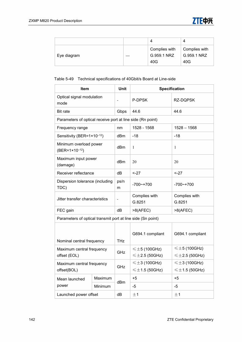
ZXMP M820 Product Description
142 ZTE Confidential Proprietary
4 4
Eye diagram --- Complies with G.959.1 NRZ 40G
Complies with G.959.1 NRZ 40G
Table 5-49 Technical specifications of 40Gbit/s Board at Line-side
Item Unit Specification
Optical signal modulation mode
- P-DPSK RZ-DQPSK
Bit rate Gbps 44.6 44.6
Parameters of optical receive port at line side (Rn point)
Frequency range nm 1528 - 1568 1528 – 1568
Sensitivity (BER=1×10–12) dBm -18 -18
Minimum overload power (BER=1×10–12)
dBm 1 1
Maximum input power (damage)
dBm 20 20
Receiver reflectance dB <-27 <-27
Dispersion tolerance (including TDC)
ps/nm
-700~+700 -700~+700
Jitter transfer characteristics - Complies with G.8251
Complies with G.8251
FEC gain dB >8(AFEC) >8(AFEC)
Parameters of optical transmit port at line side (Sn point)
Nominal central frequency
THz
G694.1 compliant G694.1 compliant
Maximum central frequency offset (EOL)
GHz ≤±5 (100GHz) ≤±2.5 (50GHz)
≤±5 (100GHz)
≤±2.5 (50GHz)
Maximum central frequency offset(BOL)
GHz ≤±3 (100GHz)
≤±1.5 (50GHz)
≤±3 (100GHz)
≤±1.5 (50GHz)
Mean launched power
Maximum dBm
+5 +5
Minimum -5 -5
Launched power offset dB ±1 ±1

ZXMP M820 Product Description
ZTE Confidential Proprietary 143
Item Unit Specification
Spectral characteristics
Maximum –20 dB bandwidth
nm 0.7 0.7
Minimum side mode compression ratio (SMCR)
dB 35 35
5.7.4 Specifications of 100Gbit/s Board
Client-side: Transmitting part of receiving end and receiving part of transmitting end.
Line-side: Receiving part of receiving end, transmitting part of transmitting end and
transmitting/receiving part of regenerator.
Technical specifications of 100Gbit/s Board at Client-side and Line-side are listed in
Table 5-50 and Table 5-51.
Table 5-50 Technical specifications of 100Gbit/s Board at Client-side
Item Unit Specification
Bit rate (optical modulation mode) Gbps 100GE 4x25.78
OTU4 4x27.95
100GE 4x25.78
OTU4 4x27.95
Optical interface category --- LR4 ER4
Target distance km 10 40
Parameters of optical receive port at client side (S point)
Frequency range nm
1294.53–1296.59
1299.02–1301.09
1303.54–1305.63
1308.09–1310.19
1294.53–1296.59
1299.02–1301.09
1303.54–1305.63
1308.09–1310.19
Sensitivity (BER=10–12) dBm
-8.6(PIN)
(single channel)
-21.4(APD)
(single channel)
Overload power(BER=10–12) dBm
+4.5
(single channel)
+4.5
(single channel)
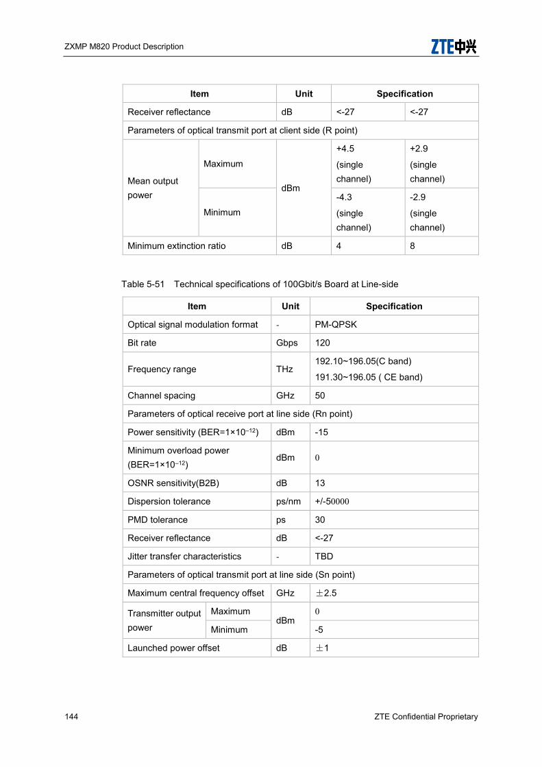
ZXMP M820 Product Description
144 ZTE Confidential Proprietary
Item Unit Specification
Receiver reflectance dB <-27 <-27
Parameters of optical transmit port at client side (R point)
Mean output power
Maximum
dBm
+4.5
(single channel)
+2.9
(single channel)
Minimum
-4.3
(single channel)
-2.9
(single channel)
Minimum extinction ratio dB 4 8
Table 5-51 Technical specifications of 100Gbit/s Board at Line-side
Item Unit Specification
Optical signal modulation format - PM-QPSK
Bit rate Gbps 120
Frequency range THz 192.10~196.05(C band)
191.30~196.05 ( CE band)
Channel spacing GHz 50
Parameters of optical receive port at line side (Rn point)
Power sensitivity (BER=1×10–12) dBm -15
Minimum overload power (BER=1×10–12)
dBm 0
OSNR sensitivity(B2B) dB 13
Dispersion tolerance ps/nm +/-50000
PMD tolerance ps 30
Receiver reflectance dB <-27
Jitter transfer characteristics - TBD
Parameters of optical transmit port at line side (Sn point)
Maximum central frequency offset GHz ±2.5
Transmitter output power
Maximum dBm
0
Minimum -5
Launched power offset dB ±1
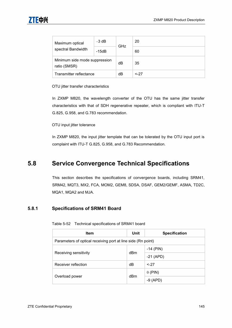
ZXMP M820 Product Description
ZTE Confidential Proprietary 145
Maximum optical spectral Bandwidth
–3 dB GHz
20
-15dB 60
Minimum side mode suppression ratio (SMSR)
dB 35
Transmitter reflectance dB <-27
OTU jitter transfer characteristics
In ZXMP M820, the wavelength converter of the OTU has the same jitter transfer
characteristics with that of SDH regenerative repeater, which is compliant with ITU-T
G.825, G.958, and G.783 recommendation.
OTU input jitter tolerance
In ZXMP M820, the input jitter template that can be tolerated by the OTU input port is
complaint with ITU-T G.825, G.958, and G.783 Recommendation.
5.8 Service Convergence Technical Specifications
This section describes the specifications of convergence boards, including SRM41,
SRM42, MQT3, MX2, FCA, MOM2, GEM8, SDSA, DSAF, GEM2/GEMF, ASMA, TD2C,
MQA1, MQA2 and MJA.
5.8.1 Specifications of SRM41 Board
Table 5-52 Technical specifications of SRM41 board
Item Unit Specification
Parameters of optical receiving port at line side (Rn point)
Receiving sensitivity dBm -14 (PIN)
-21 (APD)
Receiver reflection dB <-27
Overload power dBm 0 (PIN)
-9 (APD)
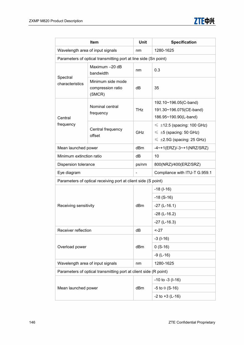
ZXMP M820 Product Description
146 ZTE Confidential Proprietary
Item Unit Specification
Wavelength area of input signals nm 1280-1625
Parameters of optical transmitting port at line side (Sn point)
Spectral characteristics
Maximum –20 dB bandwidth
nm 0.3
Minimum side mode compression ratio (SMCR)
dB 35
Central frequency
Nominal central frequency
THz
192.10~196.05(C-band)
191.30~196.075(CE-band)
186.95~190.90(L-band)
Central frequency offset
GHz
≤ 12.5 (spacing: 100 GHz)
≤ 5 (spacing: 50 GHz)
≤ 2.5G (spacing: 25 GHz)
Mean launched power dBm -4~+1(ERZ)/-3~+1(NRZ/SRZ)
Minimum extinction ratio dB 10
Dispersion tolerance ps/nm 800(NRZ)/400(ERZ/SRZ)
Eye diagram - Compliance with ITU-T G.959.1
Parameters of optical receiving port at client side (S point)
Receiving sensitivity dBm
-18 (I-16)
-18 (S-16)
-27 (L-16.1)
-28 (L-16.2)
-27 (L-16.3)
Receiver reflection dB <-27
Overload power dBm
-3 (I-16)
0 (S-16)
-9 (L-16)
Wavelength area of input signals nm 1280-1625
Parameters of optical transmitting port at client side (R point)
Mean launched power dBm
-10 to -3 (I-16)
-5 to 0 (S-16)
-2 to +3 (L-16)
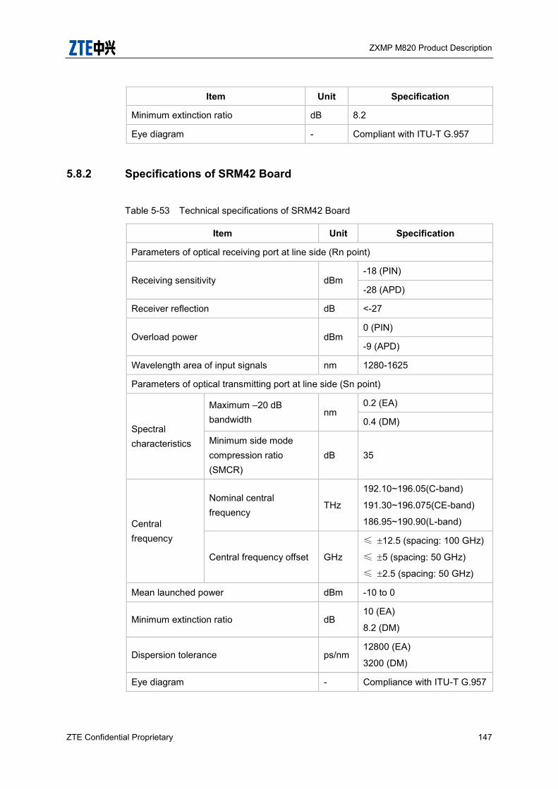
ZXMP M820 Product Description
ZTE Confidential Proprietary 147
Item Unit Specification
Minimum extinction ratio dB 8.2
Eye diagram - Compliant with ITU-T G.957
5.8.2 Specifications of SRM42 Board
Table 5-53 Technical specifications of SRM42 Board
Item Unit Specification
Parameters of optical receiving port at line side (Rn point)
Receiving sensitivity dBm -18 (PIN)
-28 (APD)
Receiver reflection dB <-27
Overload power dBm 0 (PIN)
-9 (APD)
Wavelength area of input signals nm 1280-1625
Parameters of optical transmitting port at line side (Sn point)
Spectral characteristics
Maximum –20 dB bandwidth
nm 0.2 (EA)
0.4 (DM)
Minimum side mode compression ratio (SMCR)
dB 35
Central frequency
Nominal central frequency
THz
192.10~196.05(C-band)
191.30~196.075(CE-band)
186.95~190.90(L-band)
Central frequency offset GHz
≤ 12.5 (spacing: 100 GHz)
≤ 5 (spacing: 50 GHz)
≤ 2.5 (spacing: 50 GHz)
Mean launched power dBm -10 to 0
Minimum extinction ratio dB 10 (EA)
8.2 (DM)
Dispersion tolerance ps/nm 12800 (EA)
3200 (DM)
Eye diagram - Compliance with ITU-T G.957
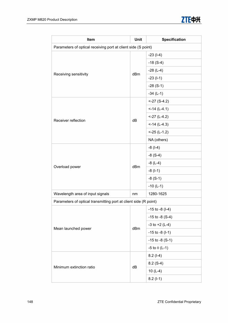
ZXMP M820 Product Description
148 ZTE Confidential Proprietary
Item Unit Specification
Parameters of optical receiving port at client side (S point)
Receiving sensitivity dBm
-23 (I-4)
-18 (S-4)
-28 (L-4)
-23 (I-1)
-28 (S-1)
-34 (L-1)
Receiver reflection dB
<-27 (S-4.2)
<-14 (L-4.1)
<-27 (L-4.2)
<-14 (L-4.3)
<-25 (L-1.2)
NA (others)
Overload power dBm
-8 (I-4)
-8 (S-4)
-8 (L-4)
-8 (I-1)
-8 (S-1)
-10 (L-1)
Wavelength area of input signals nm 1280-1625
Parameters of optical transmitting port at client side (R point)
Mean launched power dBm
-15 to -8 (I-4)
-15 to -8 (S-4)
-3 to +2 (L-4)
-15 to -8 (I-1)
-15 to -8 (S-1)
-5 to 0 (L-1)
Minimum extinction ratio dB
8.2 (I-4)
8.2 (S-4)
10 (L-4)
8.2 (I-1)
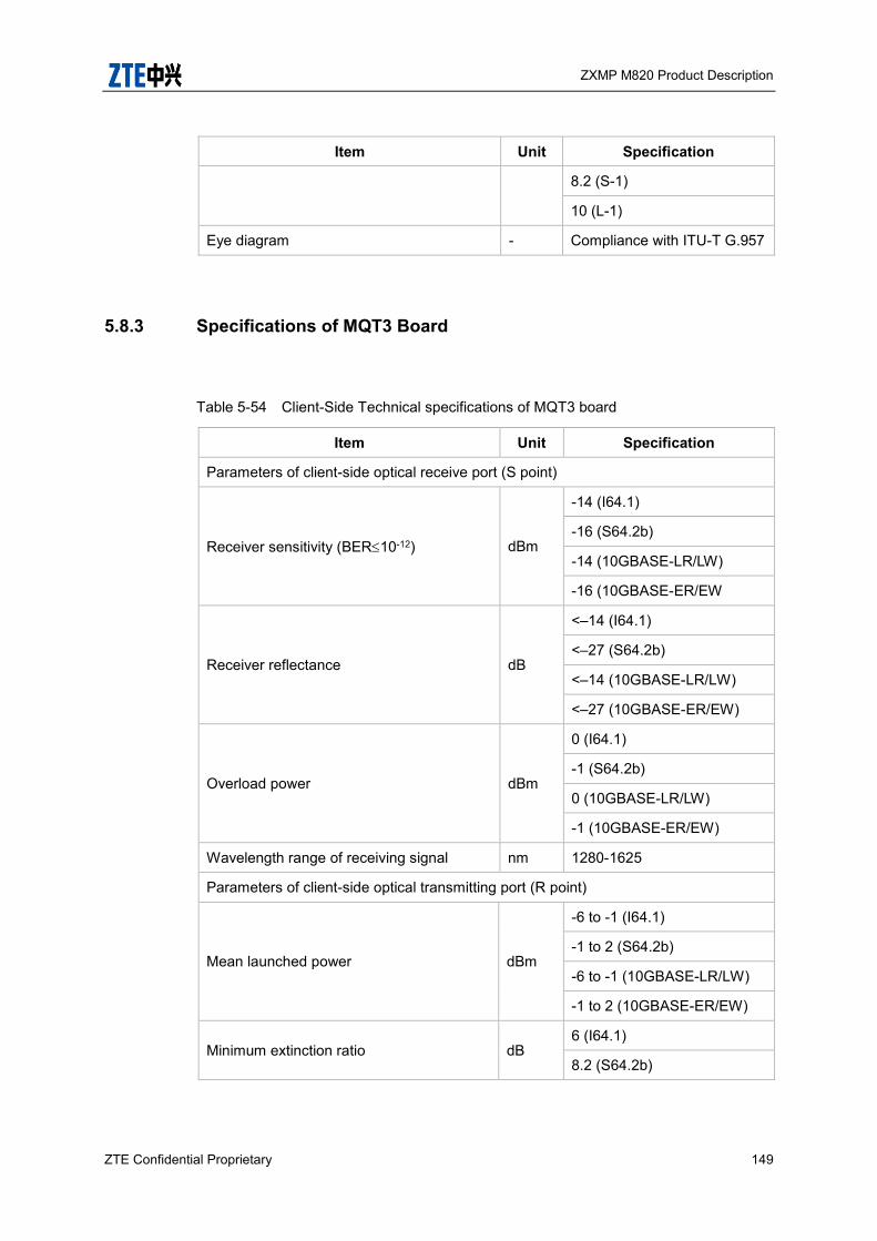
ZXMP M820 Product Description
ZTE Confidential Proprietary 149
Item Unit Specification
8.2 (S-1)
10 (L-1)
Eye diagram - Compliance with ITU-T G.957
5.8.3 Specifications of MQT3 Board
Table 5-54 Client-Side Technical specifications of MQT3 board
Item Unit Specification
Parameters of client-side optical receive port (S point)
Receiver sensitivity (BER10-12) dBm
-14 (I64.1)
-16 (S64.2b)
-14 (10GBASE-LR/LW)
-16 (10GBASE-ER/EW
Receiver reflectance dB
<–14 (I64.1)
<–27 (S64.2b)
<–14 (10GBASE-LR/LW)
<–27 (10GBASE-ER/EW)
Overload power dBm
0 (I64.1)
-1 (S64.2b)
0 (10GBASE-LR/LW)
-1 (10GBASE-ER/EW)
Wavelength range of receiving signal nm 1280-1625
Parameters of client-side optical transmitting port (R point)
Mean launched power dBm
-6 to -1 (I64.1)
-1 to 2 (S64.2b)
-6 to -1 (10GBASE-LR/LW)
-1 to 2 (10GBASE-ER/EW)
Minimum extinction ratio dB 6 (I64.1)
8.2 (S64.2b)

ZXMP M820 Product Description
150 ZTE Confidential Proprietary
Item Unit Specification
6 (10GBASE-LR/LW)
8.2 (10GBASE-ER/EW)
Eye diagram - Complies with ITU-T G.691
Table 5-55 Line-side Technical specifications of MQT3 Board
Item Unit Specification
Optical signal modulation mode - P-DPSK RZ-DQPSK
Bit rate Gbps 43.018 43.018
Parameters of line-side optical transmit port (Sn point)
Frequency range THz
192.10–196.05 (C
band)
191.30–196.075
(CE band)
192.10–196.05 (C band)
Sensitivity (BER=1×10–12) dBm -18 -18
Minimum overload (BER=1×10–12)
dBm 0 0
Max. reflectance dB <-27 <-27
Dispersion tolerance (including TDC)
ps/nm -700~+700 -700~+700
Jitter Transfer Characteristics - Complies with ITU-T G.8251
Complies with ITU-T G.8251
FEC code gain dB >8 (AFEC) >8 (AFEC)
Parameters of line-side optical receive port (Rn point)
Nominal central frequency
THz
192.10–196.05
(C band)
191.30–196.075
(CE band)
186.95–190.90
(L band)
192.10–196.05
(C band)
191.30–196.075
(CE band)
186.95–190.90
(L band)
Wavelength spacing GHz 50 50
Maximum central frequency offset
GHz ±2.5 ±2.5
Mean launched Maximum dBm +5 +5

ZXMP M820 Product Description
ZTE Confidential Proprietary 151
Item Unit Specification
power Minimum -5 -10
Launched power offset dB ±1 ±1
Spectral characteristics
Maximum –20 dB bandwidth
GHz 0.7 0.7
Minimum side mode compression ratio (SMCR)
dB 35 35
5.8.4 Specifications of MX2 Board
Table 5-56 Client-Side Technical specifications of MX2 board
Item Unit Specification
Parameters of client-side optical receive port (S point)
Receiver sensitivity (BER10-12) dBm
-14 (I64.1)
-16 (S64.2b)
-14 (10GBASE-LR/LW)
-16 (10GBASE-ER/EW
Receiver reflectance dB
<–14 (I64.1)
<–27 (S64.2b)
<–14 (10GBASE-LR/LW)
<–27 (10GBASE-ER/EW)
Overload power dBm
0 (I64.1)
-1 (S64.2b)
0 (10GBASE-LR/LW)
-1 (10GBASE-ER/EW)
Wavelength range of receiving signal nm 1280-1625
Parameters of client-side optical transmitting port (R point)
Mean launched power dBm
-6 to -1 (I64.1)
-1 to 2 (S64.2b)
-6 to -1 (10GBASE-LR/LW)
-1 to 2 (10GBASE-ER/EW)
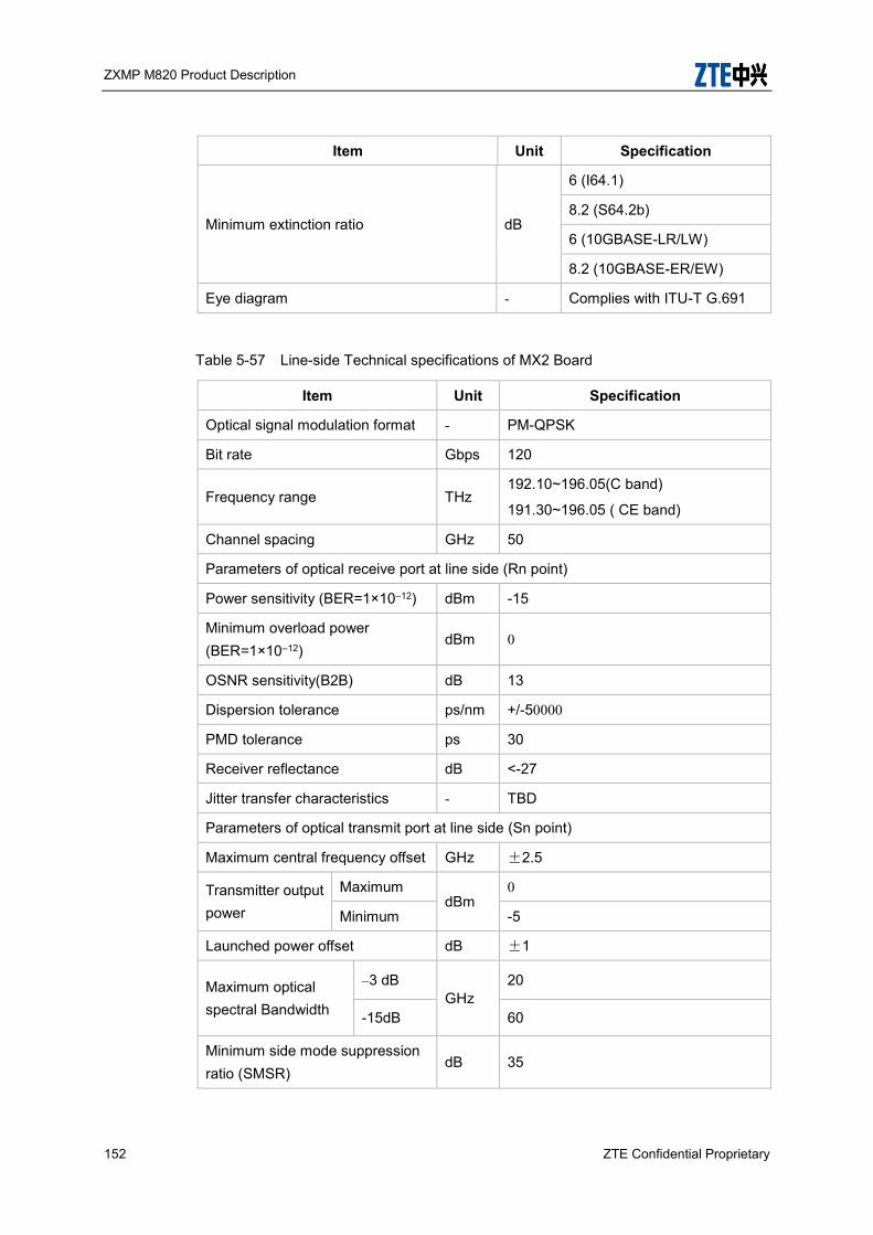
ZXMP M820 Product Description
152 ZTE Confidential Proprietary
Item Unit Specification
Minimum extinction ratio dB
6 (I64.1)
8.2 (S64.2b)
6 (10GBASE-LR/LW)
8.2 (10GBASE-ER/EW)
Eye diagram - Complies with ITU-T G.691
Table 5-57 Line-side Technical specifications of MX2 Board
Item Unit Specification
Optical signal modulation format - PM-QPSK
Bit rate Gbps 120
Frequency range THz 192.10~196.05(C band)
191.30~196.05 ( CE band)
Channel spacing GHz 50
Parameters of optical receive port at line side (Rn point)
Power sensitivity (BER=1×10–12) dBm -15
Minimum overload power (BER=1×10–12)
dBm 0
OSNR sensitivity(B2B) dB 13
Dispersion tolerance ps/nm +/-50000
PMD tolerance ps 30
Receiver reflectance dB <-27
Jitter transfer characteristics - TBD
Parameters of optical transmit port at line side (Sn point)
Maximum central frequency offset GHz ±2.5
Transmitter output power
Maximum dBm
0
Minimum -5
Launched power offset dB ±1
Maximum optical spectral Bandwidth
–3 dB GHz
20
-15dB 60
Minimum side mode suppression ratio (SMSR)
dB 35
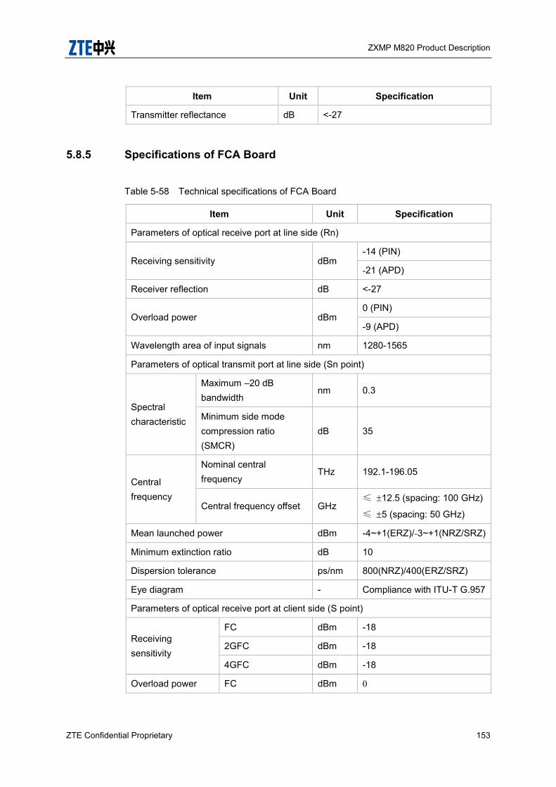
ZXMP M820 Product Description
ZTE Confidential Proprietary 153
Item Unit Specification
Transmitter reflectance dB <-27
5.8.5 Specifications of FCA Board
Table 5-58 Technical specifications of FCA Board
Item Unit Specification
Parameters of optical receive port at line side (Rn)
Receiving sensitivity dBm -14 (PIN)
-21 (APD)
Receiver reflection dB <-27
Overload power dBm 0 (PIN)
-9 (APD)
Wavelength area of input signals nm 1280-1565
Parameters of optical transmit port at line side (Sn point)
Spectral characteristic
Maximum –20 dB bandwidth
nm 0.3
Minimum side mode compression ratio (SMCR)
dB 35
Central frequency
Nominal central frequency
THz 192.1-196.05
Central frequency offset GHz ≤ 12.5 (spacing: 100 GHz)
≤ 5 (spacing: 50 GHz)
Mean launched power dBm -4~+1(ERZ)/-3~+1(NRZ/SRZ)
Minimum extinction ratio dB 10
Dispersion tolerance ps/nm 800(NRZ)/400(ERZ/SRZ)
Eye diagram - Compliance with ITU-T G.957
Parameters of optical receive port at client side (S point)
Receiving sensitivity
FC dBm -18
2GFC dBm -18
4GFC dBm -18
Overload power FC dBm 0

ZXMP M820 Product Description
154 ZTE Confidential Proprietary
Item Unit Specification
2GFC dBm 0
4GFC dBm 0
Parameters of optical transmit port at client side (R point)
Output power
FC dBm -4.5
2GFC dBm -4.5
4GFC dBm -4.5
5.8.6 Specifications of MOM2 Board
Table 5-59 Specification of MOM2 Board
Item Unit Specification
Parameters of optical receive port at line side (Rn point)
Receiving sensitivity dBm -14 (PIN)
-21 (APD)
Receiver reflection dB <-27
Overload power dBm 0 (PIN)
-9 (APD)
Wavelength area of input signals nm 1280-1565
Parameters of optical transmit port at line side (Sn point)
Spectral characteristic
Maximum –20 dB bandwidth
nm 0.3
Minimum side mode compression ratio (SMCR)
dB 35
Central frequency
Nominal central frequency
THz 192.1-196.05
Central frequency offset GHz ≤ 12.5 (spacing: 100 GHz)
≤ 5 (spacing: 50 GHz)
Mean launched power dBm -4~+1(ERZ)/-3~+1(NRZ/SRZ)
Minimum extinction ratio dB 10

ZXMP M820 Product Description
ZTE Confidential Proprietary 155
Item Unit Specification
Dispersion tolerance ps/nm 800(NRZ)/400(ERZ/SRZ)
Eye diagram - Compliance with ITU-T G.957
Parameters of optical receive port at client side (S point)
Receiving sensitivity
FC
dBm
-18
2GFC -18
4GFC -18
1000BASE-SX -17
1000BASE-LX -19
1000BASE-LH1 -20
1000BASE-ZX -22
Overload power
FC
dBm
0
2GFC 0
4GFC 0
1000BASE-SX 0
1000BASE-LX -3
1000BASE-LH1 -3
1000BASE-ZX -3
Parameters of optical transmit port at client side (R point)
Output power
FC
dBm
-4.5
2GFC -4.5
4GFC -4.5
1000BASE-SX -9.5 to -3 (1000BASE-SX)
1000BASE-LX -11 to -3 (1000BASE-LX)
1000BASE-LH1 -4 to 0 (1000BASE-LH1)
1000BASE-ZX -2 to +3 (1000BASE-ZX)
5.8.7 Specifications of GEM8 Board
Table 5-60 Technical specifications of GEM8 Board
Item Unit Specification

ZXMP M820 Product Description
156 ZTE Confidential Proprietary
Item Unit Specification
Parameters of optical receive port at line side (Rn point)
Receiving sensitivity dBm -14 (PIN)
-21 (APD)
Receiver reflection dB <-27
Overload power dBm 0 (PIN)
-9 (APD)
Wavelength area of input signals nm 1250-1620
Parameters of optical transmit port at line side (Sn point)
Spectral characteristics
Maximum –20 dB bandwidth
nm 0.3
Minimum side mode compression ratio (SMCR)
dB 35
Central frequency
Nominal central frequency THz 192.10~196.05(C-band)
191.30~196.075(CE-band)
Central frequency offset GHz
≤ 12.5 (spacing: 100 GHz)
≤ 5 (spacing: 50 GHz)
Mean launched power dBm -5 to 0
Minimum extinction ratio dB 10
Dispersion tolerance ps/nm 800
Eye diagram - Compliance with ITU-T G.959.1
Parameters of optical receive port at client side (S point)
Receiving sensitivity dBm -17 (1000BASE-SX)
-19 (1000BASE-LX)
Overload power dBm 0 (1000BASE-SX)
-3 (1000BASE-LX)
Parameters of optical transmit port at client side (R point)
Mean launched power dBm -9.5 to -3 (1000BASE-SX)
-11 to -3 (1000BASE-LX)

ZXMP M820 Product Description
ZTE Confidential Proprietary 157
5.8.8 Specifications of SDSA Board
Table 5-61 Specification of SDSA Board
Item Unit Specification
Parameters of optical receive port at line side (Rn point)
Receiving sensitivity dBm -18 (PIN)
-25 (APD)
Receiver reflection dB <-27
Overload power dBm 0 (PIN)
-9 (APD)
Wavelength area of input signals nm 1280-1565
Parameters of optical transmit port at line side (Sn point)
Spectral characteristic
Maximum –20 dB bandwidth
nm 0.2 (EA)
0.4 (DM)
Minimum side mode compression ratio (SMCR)
dB 35
Central frequency
Nominal central frequency
THz 192.1-196.05 (C band)
191.30~196.05 (CE band)
Central frequency offset
GHz ≤ 12.5 (100 GHz spacing)
≤ 5 (50 GHz spacing)
Mean launched power dBm -10 to 0
Minimum extinction ratio dB 10 (EA)
8.2 (DM)
Dispersion tolerance ps/nm 12800 (EA)/3200/6400 (DM)
Eye diagram - Compliance with ITU-T G.957
Parameters of optical receive port at client side (S point)
Receiving sensitivity dBm
-17 (1000BASE-SX)
-19 (1000BASE-LX)
-20 (1000BASE-LH1)
-22 (1000BASE-ZX)
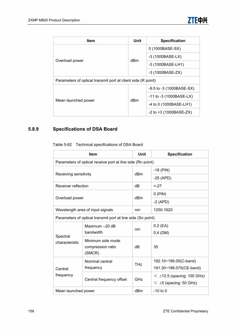
ZXMP M820 Product Description
158 ZTE Confidential Proprietary
Item Unit Specification
Overload power dBm
0 (1000BASE-SX)
-3 (1000BASE-LX)
-3 (1000BASE-LH1)
-3 (1000BASE-ZX)
Parameters of optical transmit port at client side (R point)
Mean launched power dBm
-9.5 to -3 (1000BASE-SX)
-11 to -3 (1000BASE-LX)
-4 to 0 (1000BASE-LH1)
-2 to +3 (1000BASE-ZX)
5.8.9 Specifications of DSA Board
Table 5-62 Technical specifications of DSA Board
Item Unit Specification
Parameters of optical receive port at line side (Rn point)
Receiving sensitivity dBm -18 (PIN)
-25 (APD)
Receiver reflection dB <-27
Overload power dBm 0 (PIN)
-2 (APD)
Wavelength area of input signals nm 1250-1620
Parameters of optical transmit port at line side (Sn point)
Spectral characteristic
Maximum –20 dB bandwidth
nm 0.2 (EA)
0.4 (DM)
Minimum side mode compression ratio (SMCR)
dB 35
Central frequency
Nominal central frequency
THz 192.10~196.05(C-band)
191.30~196.075(CE-band)
Central frequency offset GHz ≤ 12.5 (spacing: 100 GHz)
≤ 5 (spacing: 50 GHz)
Mean launched power dBm -10 to 0

ZXMP M820 Product Description
ZTE Confidential Proprietary 159
Item Unit Specification
Minimum extinction ratio dB 10 (EA)
8.2 (DM)
Dispersion tolerance ps/nm 12800 (EA)/3200 (DM)
Eye diagram - Compliance with ITU-T G.957
Parameters of optical receive port at client side (S point)
Receiving sensitivity dBm
-17 (1000BASE-SX)
-19 (1000BASE-LX)
-20 (1000BASE-LH1)
-22 (1000BASE-ZX)
-25 (100-SM-LL-L)
-20 (100-SM-LL-I)
-13 (100-M5-SL-I)
Overload power dBm
0 (1000BASE-SX)
-3 (1000BASE-LX)
-3 (1000BASE-LH1)
-3 (1000BASE-ZX)
-3 (100-SM-LL-L)
-3 (100-SM-LL-I)
-1.3 (100-M5-SL-I)
Parameters of optical transmit port at client side (R point)
Mean launched power dBm
-9.5 to -3 (1000BASE-SX)
-11 to -3 (1000BASE-LX)
-4 to 0 (1000BASE-LH1)
-2 to +3 (1000BASE-ZX)
-9 to -3 (100-SM-LL-L)
-12 to -3 (100-SM-LL-I)
-7.3 to +1.3 (100-M5-SL-I)

ZXMP M820 Product Description
160 ZTE Confidential Proprietary
5.8.10 Specifications of DSAF Board
Table 5-63 Technical specifications of DSAF Board
Item Unit Specification
Parameters of optical receiving port at line side (Rn point)
Receiving sensitivity dBm -21 (PIN)
-25 (APD)
Receiver reflection dB <-27
Overload power dBm 0 (PIN)
-9 (APD)
Wavelength area of input signals nm 1250-1620
Parameters of optical transmitting port at line side (Sn point)
Spectral characteristics
Maximum –20 dB bandwidth
nm 0.2 (EA)
0.5 (DM)
Minimum side mode compression ratio (SMCR)
dB 30
Central frequency
Nominal central frequency
THz 192.10~196.05(C-band)
191.30~196.075(CE-band)
Central frequency offset GHz ≤ 12.5 (spacing: 100 GHz)
≤ 5 (spacing: 50 GHz)
Mean launched power dBm -10 to 7
Minimum extinction ratio dB 10 (EA)
8.2 (DM)
Dispersion tolerance ps/nm 12800 (EA)
6500 (DM)
Eye diagram - Compliance with ITU-T G.957
Parameters of optical receiving port at client side (S point)
Receiving sensitivity dBm
-17 (1000BASE-SX)
-19 (1000BASE-LX)
-20 (1000BASE-LH1)
-22 (1000BASE-ZX)
Overload power dBm 0 (1000BASE-SX)

ZXMP M820 Product Description
ZTE Confidential Proprietary 161
Item Unit Specification
-3 (1000BASE-LX)
-3 (1000BASE-LH1)
-3 (1000BASE-ZX)
Parameters of optical transmitting port at client side (R point)
Mean launched power dBm
-9.5 to -3 (1000BASE-SX)
-11 to -3 (1000BASE-LX)
-4 to 0 (1000BASE-LH1)
-2 to +3 (1000BASE-ZX)
5.8.11 Specifications of GEM2/GEMF Board
Table 5-64 Technical specifications of GEM2/GEMF Board
Item Unit Specification
Parameters of optical receiving port at line side (Rn point)
Receiving sensitivity dBm -21 (PIN)
-28 (APD)
Receiver reflection dB <-27
Overload power dBm 0 (PIN)
-9 (APD)
Wavelength area of input signals nm 1250-1620
Parameters of optical transmitting port at line side (Sn point)
Spectral characteristics
Maximum –20 dB bandwidth
nm 0.2 (EA)
0.4 (DM)
Minimum side mode compression ratio (SMCR)
dB 35
Central frequency
Nominal central frequency
THz 192.10~196.05(C-band)
191.30~196.075(CE-band)
Central frequency offset GHz ≤ 12.5 (spacing: 100 GHz)
≤ 5 (spacing: 50 GHz)
Mean launched power dBm -10 to 0

ZXMP M820 Product Description
162 ZTE Confidential Proprietary
Item Unit Specification
Minimum extinction ratio dB 10 (EA)
8.2 (DM)
Dispersion tolerance ps/nm 12800 (EA)
3200 (DM)
Eye diagram - Compliance with ITU-T G.957
Parameters of optical receiving port at client side (S point)
Receiving sensitivity dBm
-17 (1000BASE-SX)
-19 (1000BASE-LX)
-20 (1000BASE-LH1)
-22 (1000BASE-ZX)
Overload power dBm
0 (1000BASE-SX)
-3 (1000BASE-LX)
-3 (1000BASE-LH1)
-3 (1000BASE-ZX)
Parameters of optical transmitting port at client side (R point)
Mean launched power dBm
-9.5 to -3 (1000BASE-SX)
-11 to -3 (1000BASE-LX)
-4 to 0 (1000BASE-LH1)
-2 to +3 (1000BASE-ZX)
5.8.12 Specifications of ASMA Board
Table 5-65 Technical specifications of ASMA Board
Item Unit Specification
Parameters of WDM-side optical receive port (Rn point)
Receiver sensitivity dBm <-14 (PIN)
<-21 (APD)
Receiver reflection dB <–27
Overload power dBm >0 (PIN)
>-9 (APD)
Wavelength range of input signal nm 1280~1625

ZXMP M820 Product Description
ZTE Confidential Proprietary 163
Item Unit Specification
Parameters of WDM-side optical transmit port (Sn point)
Maximum -20 dB bandwidth nm 0.3
Minimum side mode suppression ratio
dB 35
Nominal central frequency THz 192.10~196.05 (C band)
191.30~196.075 (CE band)
Central frequency offset GHz
≤±12.5 (wavelength spacing:
100GHz)
≤±5 (wavelength spacing:
50GHz)
Mean launched power dBm -3~+1(NRZ)
Minimum extinction ratio dB 10
Dispersion tolerance ps/nm 800
Eye diagram - Comply with ITU-T G.691 Recommendation
Parameters of client-side optical receive port (S point)
Receiver sensitivity dBm
<-17 (1000BASE-SX)
<-19 (1000BASE-LX)
<-14 (10GBASE-LR)
<-15 (10GBASE-ER
Overload power dBm
>0 (1000BASE-SX)
>-3 (1000BASE-LX)
>0.5 (10GBASE-LR)
>-1 (10GBASE-ER)
Parameters of client-side optical transmit port (R point)
Mean launched power dBm
-9.5 to -3 (1000BASE-SX)
-11 to -3 (1000BASE-LX)
-8.2 to 0.5 (10GBASE-LR)
-4.7 to 4.0 (10GBASE-ER)

ZXMP M820 Product Description
164 ZTE Confidential Proprietary
5.8.13 Specifications of TD2C Board
Table 5-66 Technical specifications of TD2C board
Item Unit Specification
Parameters of input port (S point)
Receiving sensitivity (BER10-12) dBm
-14 (I64.1)
-16 (S64.2b)
-12.6 (10GBASE-LR/LW)
-14.1 (10GBASE-ER/EW)
-14 (1200-SM-LL-L)
Overload power dBm
0 (I64.1)
-1 (S64.2b)
0 (10GBASE-LR/LW)
-1 (10GBASE-ER/EW)
0 (1200-SM-LL-L)
Wavelength of input signals nm 1280 to 1565
Parameters of output port (Sn point)
Maximum bandwidth @ -20 dB nm 0.3
Minimum side mode compression ratio (SMCR)
dB 35
Nominal central frequency THz 192.1 to 196.0
Central frequency offset GHz ≤±12.5 (spacing: 100 GHz)
Mean launched power dBm -3 to +1
Minimum extinction ratio dB 8.2
Dispersion tolerance ps/nm 800 (G.652)
Eye diagram - ITU-T G.691
Parameters of input port (Rn point)
Receiving sensitivity (BER10-12) dBm -14 (PIN)
-21 (APD)
Receiver reflection dB <-27
Overload power dBm 0 (PIN)
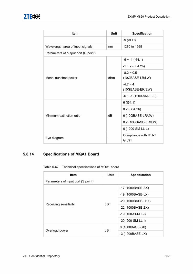
ZXMP M820 Product Description
ZTE Confidential Proprietary 165
Item Unit Specification
-9 (APD)
Wavelength area of input signals nm 1280 to 1565
Parameters of output port (R point)
Mean launched power dBm
-6 ~ -1 (I64.1)
-1 ~ 2 (S64.2b)
-8.2 ~ 0.5 (10GBASE-LR/LW)
-4.7 ~ 4 (10GBASE-ER/EW)
-6 ~ -1 (1200-SM-LL-L)
Minimum extinction ratio dB
6 (I64.1)
8.2 (S64.2b)
6 (10GBASE-LR/LW)
8.2 (10GBASE-ER/EW)
6 (1200-SM-LL-L)
Eye diagram - Compliance with ITU-T G.691
5.8.14 Specifications of MQA1 Board
Table 5-67 Technical specifications of MQA1 board
Item Unit Specification
Parameters of input port (S point)
Receiving sensitivity dBm
-17 (1000BASE-SX)
-19 (1000BASE-LX)
-20 (1000BASE-LH1)
-22 (1000BASE-ZX)
-19 (100-SM-LL-I)
-20 (200-SM-LL-I)
Overload power dBm 0 (1000BASE-SX)
-3 (1000BASE-LX)
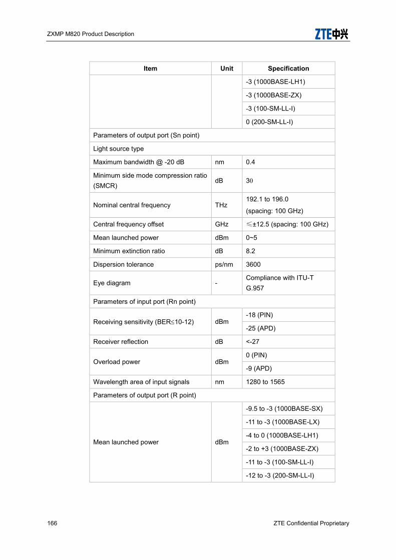
ZXMP M820 Product Description
166 ZTE Confidential Proprietary
Item Unit Specification
-3 (1000BASE-LH1)
-3 (1000BASE-ZX)
-3 (100-SM-LL-I)
0 (200-SM-LL-I)
Parameters of output port (Sn point)
Light source type
Maximum bandwidth @ -20 dB nm 0.4
Minimum side mode compression ratio (SMCR)
dB 30
Nominal central frequency THz 192.1 to 196.0
(spacing: 100 GHz)
Central frequency offset GHz ≤±12.5 (spacing: 100 GHz)
Mean launched power dBm 0~5
Minimum extinction ratio dB 8.2
Dispersion tolerance ps/nm 3600
Eye diagram - Compliance with ITU-T G.957
Parameters of input port (Rn point)
Receiving sensitivity (BER10-12) dBm -18 (PIN)
-25 (APD)
Receiver reflection dB <-27
Overload power dBm 0 (PIN)
-9 (APD)
Wavelength area of input signals nm 1280 to 1565
Parameters of output port (R point)
Mean launched power dBm
-9.5 to -3 (1000BASE-SX)
-11 to -3 (1000BASE-LX)
-4 to 0 (1000BASE-LH1)
-2 to +3 (1000BASE-ZX)
-11 to -3 (100-SM-LL-I)
-12 to -3 (200-SM-LL-I)
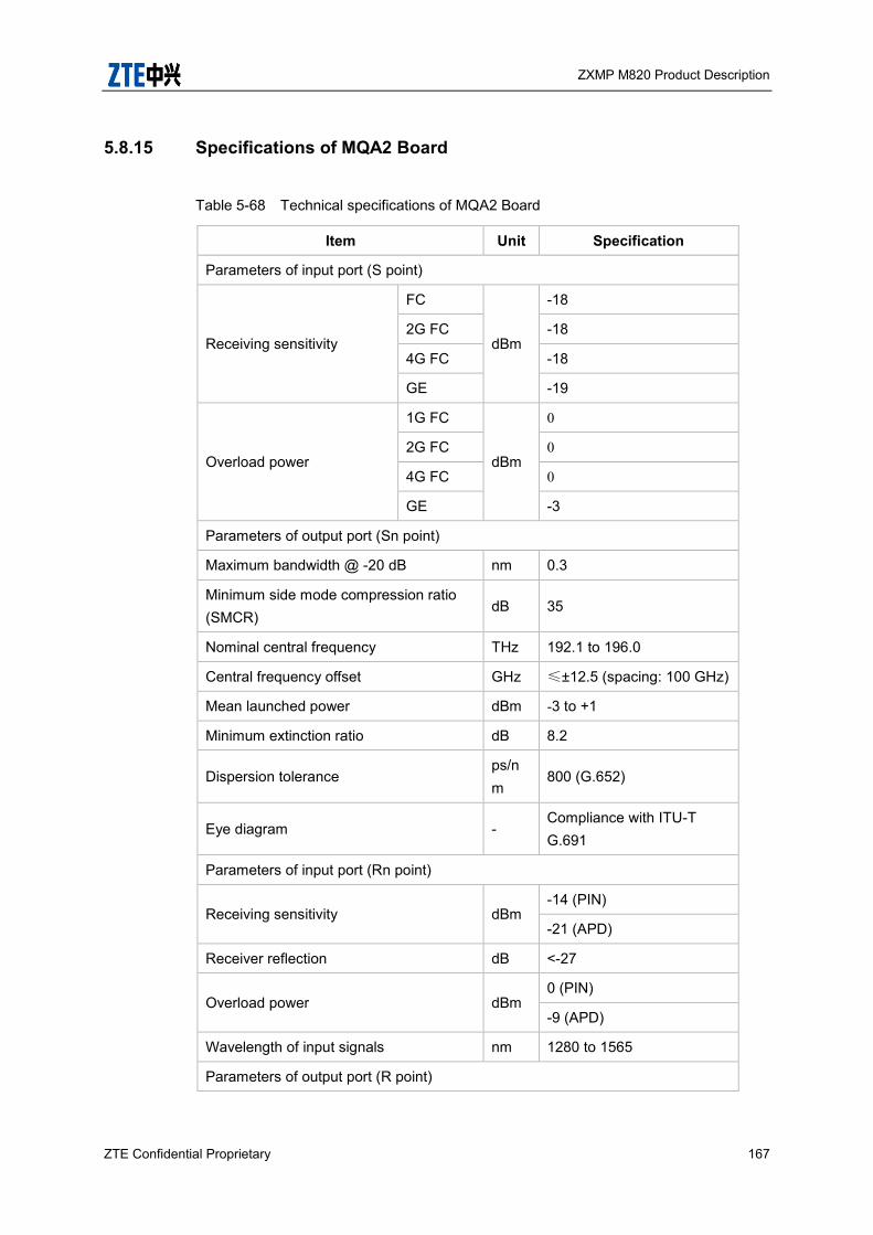
ZXMP M820 Product Description
ZTE Confidential Proprietary 167
5.8.15 Specifications of MQA2 Board
Table 5-68 Technical specifications of MQA2 Board
Item Unit Specification
Parameters of input port (S point)
Receiving sensitivity
FC
dBm
-18
2G FC -18
4G FC -18
GE -19
Overload power
1G FC
dBm
0
2G FC 0
4G FC 0
GE -3
Parameters of output port (Sn point)
Maximum bandwidth @ -20 dB nm 0.3
Minimum side mode compression ratio (SMCR)
dB 35
Nominal central frequency THz 192.1 to 196.0
Central frequency offset GHz ≤±12.5 (spacing: 100 GHz)
Mean launched power dBm -3 to +1
Minimum extinction ratio dB 8.2
Dispersion tolerance ps/nm
800 (G.652)
Eye diagram - Compliance with ITU-T G.691
Parameters of input port (Rn point)
Receiving sensitivity dBm -14 (PIN)
-21 (APD)
Receiver reflection dB <-27
Overload power dBm 0 (PIN)
-9 (APD)
Wavelength of input signals nm 1280 to 1565
Parameters of output port (R point)

ZXMP M820 Product Description
168 ZTE Confidential Proprietary
Item Unit Specification
Mean launched power
1G FC
dBm
-4.5
2G FC -4.5
4G FC -4.5
GE -11~0
5.8.16 Specifications of MJA Board
Table 5-69 Technical specifications of MJA board
Item Unit Specification
Parameters of input port (S point)
Receiving sensitivity dBm
-17 (1000BASE-SX)
-19 (1000BASE-LX)
-20 (1000BASE-LH1)
-22 (1000BASE-ZX)
-19 (100-SM-LL-I)
-20 (200-SM-LL-I)
Overload power dBm
0 (1000BASE-SX)
-3 (1000BASE-LX)
-3 (1000BASE-LH1)
-3 (1000BASE-ZX)
-3 (100-SM-LL-I)
0 (200-SM-LL-I)
Parameters of output port (R point)
Mean launched power dBm
-9.5 to -3 (1000BASE-SX)
-11 to -3 (1000BASE-LX)
-4 to 0 (1000BASE-LH1)
-2 to +3 (1000BASE-ZX)
-11 to -3 (100-SM-LL-I)
-12 to -3 (200-SM-LL-I)

ZXMP M820 Product Description
ZTE Confidential Proprietary 169
5.9 Electrical Cross-connection Subsystem
Specifications
5.9.1 Specifications of CH1 Board
Table 5-70 Technical specifications of CH1 Board
Item Unit Specification
Parameters of optical receiving port (S point) at client side
Receiving sensitivity (BER10-12) dBm
-17 (1000BASE-SX)
-19 (1000BASE-LX)
-20 (1000BASE-LH1)
-22 (1000BASE-ZX)
-25 (100-SM-LL-L)
-20 (100-SM-LL-I)
-13 (100-M5-SL-I)
-18 (I-16)
-18 (S-16.1)
-18 (S-16.2)
-27 (L-16.1/L-16.2/L-16.3)
-27 (L-16.1/L-16.2/L-16.3)
Overload power dBm
0 (1000BASE-SX)
-3 (1000BASE-LX)
-3 (1000BASE-LH1)
-3 (1000BASE-ZX)
-3 (100-SM-LL-L)
-3 (100-SM-LL-I)
-1.3 (100-M5-SL-I)
-3 (I-16)
0 (S-16.1)
0 (S-16.2)
-9 (L-16.1/L-16.2/L-16.3)

ZXMP M820 Product Description
170 ZTE Confidential Proprietary
Item Unit Specification
-9 (L-16.1/L-16.2/L-16.3)
Parameters of optical transmit port (R point) at client side
Average optical transmit power dBm
-9.5 ~ -3 (1000BASE-SX)
-11 ~ -3 (1000BASE-LX)
-4 ~ 0 (1000BASE-LH1)
-2 ~ 3 (1000BASE-ZX)
-9 ~ -3 (100-SM-LL-L)
-12 ~ -3 (100-SM-LL-I)
-7.3 ~ 1.3 (100-M5-SL-I)
-10 ~ -3 (I-16)
-5 ~ 0 (S-16.1)
-5 ~ 0 (S-16.2)
-2 ~ 3 (L-16.1/L-16.2/L-16.3)
-2 ~ 3 (L-16.1/L-16.2/L-16.3)
5.9.2 Specifications of CO2 Board
Table 5-71 Technical specifications of CO2 board
Item Unit Specification
Parameters of optical receiving port (S point) at client side
Receiving sensitivity (BER10-12) dBm
-14 (I-64.1)
-16.5 (S-64.2b)
-24 (L-64.2c)
-14 (10GBASE-LR/LW)
-16 (10GBASE-ER/EW)
Overload power dBm
-1 (I-64.1)
-1 (S-64.2b)
-9 (L-64.2c)
0 (10GBASE-LR/LW)

ZXMP M820 Product Description
ZTE Confidential Proprietary 171
Item Unit Specification
-1 (10GBASE-ER/EW)
Parameters of optical transmit port (R point) at client side
Average optical transmit power dBm
-5 ~ -1 (I-64.1)
0 ~ 2 (S-64.2b)
-1 ~ 4 (L-64.2c)
-6~ -1 (10GBASE-LR/LW)
-1 ~ 2 (10GBASE-ER/EW)
5.9.3 Specifications of CQ2 Board
Table 5-72 Technical specifications of CQ2 board
Item Unit Specification
Parameters of optical receiving port (S point) at client side
Receiving sensitivity (BER10-12) dBm
-14 (I-64.1)
-16.5 (S-64.2b)
-24 (L-64.2c)
-14 (10GBASE-LR/LW)
-16 (10GBASE-ER/EW)
Overload power dBm
-1 (I-64.1)
-1 (S-64.2b)
-9 (L-64.2c)
0 (10GBASE-LR/LW)
-1 (10GBASE-ER/EW)
Parameters of optical transmit port (R point) at client side
Average optical transmit power dBm
-5 ~ -1 (I-64.1)
0 ~ 2 (S-64.2b)
-1 ~ 4 (L-64.2c)
-6~ -1 (10GBASE-LR/LW)
-1 ~ 2 (10GBASE-ER/EW)

ZXMP M820 Product Description
172 ZTE Confidential Proprietary
5.9.4 Specifications of CS3 Board
Table 5-73 Technical specifications of CS3 board
Item Unit Specification
Parameters of optical receiving port (S point) at client side
Frequency range nm 1280 ~1625
Sensitivity (BER 1×10–12) dBm -6
Overload power dBm 3
Maximum reflectance dB 27
Chromatic Dispersion tolerance Ps/nm
-10 ~ 60
Mean DGD tolerance ps 2.5
Parameters of optical transmit port (R point) at client side
Mean output power dBm 0 ~ 3
Frequency range
ITU-T G.693 VSR2000-3R2/3/5 compliant (STM-256)
G.959.1 P1S1 3C2/3/5 compliant (OTU3)
Minimum SMSR dB 35
jitter performance Conform to G.8251
Eye Mask Conform to G.959.1 NRZ 40G
5.9.5 Specifications of CD3 Board
Table 5-74 Technical specifications of CD3 Board for 40GBASE-LR4
Item Unit Specification
Parameters of optical receiving port (S point) at client side
Signaling rate, each lane (range) GBd 10.3125 ± 100 ppm
Lane wavelengths (range) nm
1264.5 to 1277.5
1284.5 to 1297.5
1304.5 to 1317.5
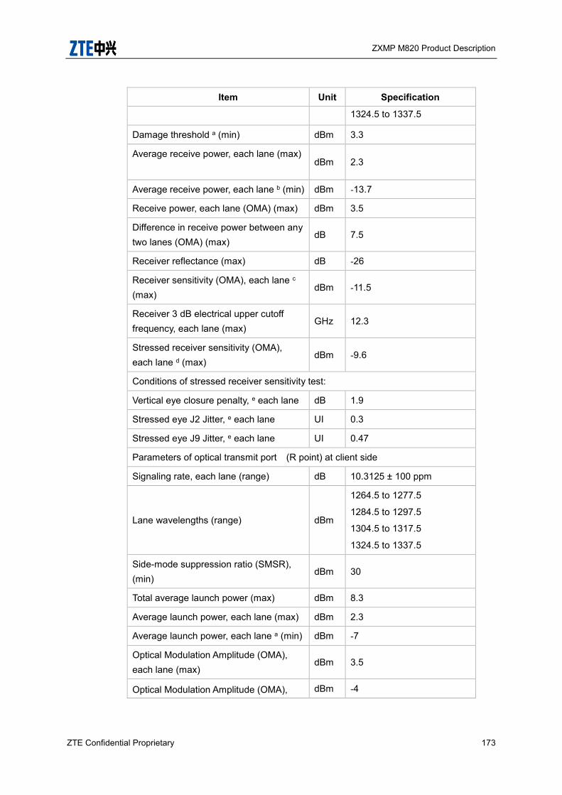
ZXMP M820 Product Description
ZTE Confidential Proprietary 173
Item Unit Specification
1324.5 to 1337.5
Damage threshold a (min) dBm 3.3
Average receive power, each lane (max)
dBm 2.3
Average receive power, each lane b (min) dBm -13.7
Receive power, each lane (OMA) (max) dBm 3.5
Difference in receive power between any two lanes (OMA) (max)
dB 7.5
Receiver reflectance (max) dB -26
Receiver sensitivity (OMA), each lane c (max)
dBm -11.5
Receiver 3 dB electrical upper cutoff frequency, each lane (max)
GHz 12.3
Stressed receiver sensitivity (OMA), each lane d (max)
dBm -9.6
Conditions of stressed receiver sensitivity test:
Vertical eye closure penalty, e each lane dB 1.9
Stressed eye J2 Jitter, e each lane UI 0.3
Stressed eye J9 Jitter, e each lane UI 0.47
Parameters of optical transmit port (R point) at client side
Signaling rate, each lane (range) dB 10.3125 ± 100 ppm
Lane wavelengths (range) dBm
1264.5 to 1277.5
1284.5 to 1297.5
1304.5 to 1317.5
1324.5 to 1337.5
Side-mode suppression ratio (SMSR), (min)
dBm 30
Total average launch power (max) dBm 8.3
Average launch power, each lane (max) dBm 2.3
Average launch power, each lane a (min) dBm -7
Optical Modulation Amplitude (OMA), each lane (max)
dBm 3.5
Optical Modulation Amplitude (OMA), dBm -4
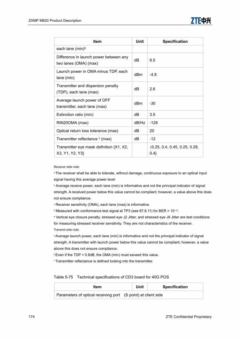
ZXMP M820 Product Description
174 ZTE Confidential Proprietary
Item Unit Specification
each lane (min)b
Difference in launch power between any two lanes (OMA) (max)
dB 6.5
Launch power in OMA minus TDP, each lane (min)
dBm -4.8
Transmitter and dispersion penalty (TDP), each lane (max)
dB 2.6
Average launch power of OFF transmitter, each lane (max)
dBm -30
Extinction ratio (min) dB 3.5
RIN20OMA (max) dB/Hz -128
Optical return loss tolerance (max) dB 20
Transmitter reflectance c (max) dB -12
Transmitter eye mask definition {X1, X2, X3, Y1, Y2, Y3}
{0.25, 0.4, 0.45, 0.25, 0.28, 0.4}
Receiver side note:
a The receiver shall be able to tolerate, without damage, continuous exposure to an optical input
signal having this average power level b Average receive power, each lane (min) is informative and not the principal indicator of signal
strength. A received power below this value cannot be compliant; however, a value above this does
not ensure compliance. c Receiver sensitivity (OMA), each lane (max) is informative. d Measured with conformance test signal at TP3 (see 87.8.11) for BER = 10–12. e Vertical eye closure penalty, stressed eye J2 Jitter, and stressed eye J9 Jitter are test conditions
for measuring stressed receiver sensitivity. They are not characteristics of the receiver.
Transmit side note:
a Average launch power, each lane (min) is informative and not the principal indicator of signal
strength. A transmitter with launch power below this value cannot be compliant; however, a value
above this does not ensure compliance. b Even if the TDP < 0.8dB, the OMA (min) must exceed this value. c Transmitter reflectance is defined looking into the transmitter.
Table 5-75 Technical specifications of CD3 board for 40G POS
Item Unit Specification
Parameters of optical receiving port (S point) at client side
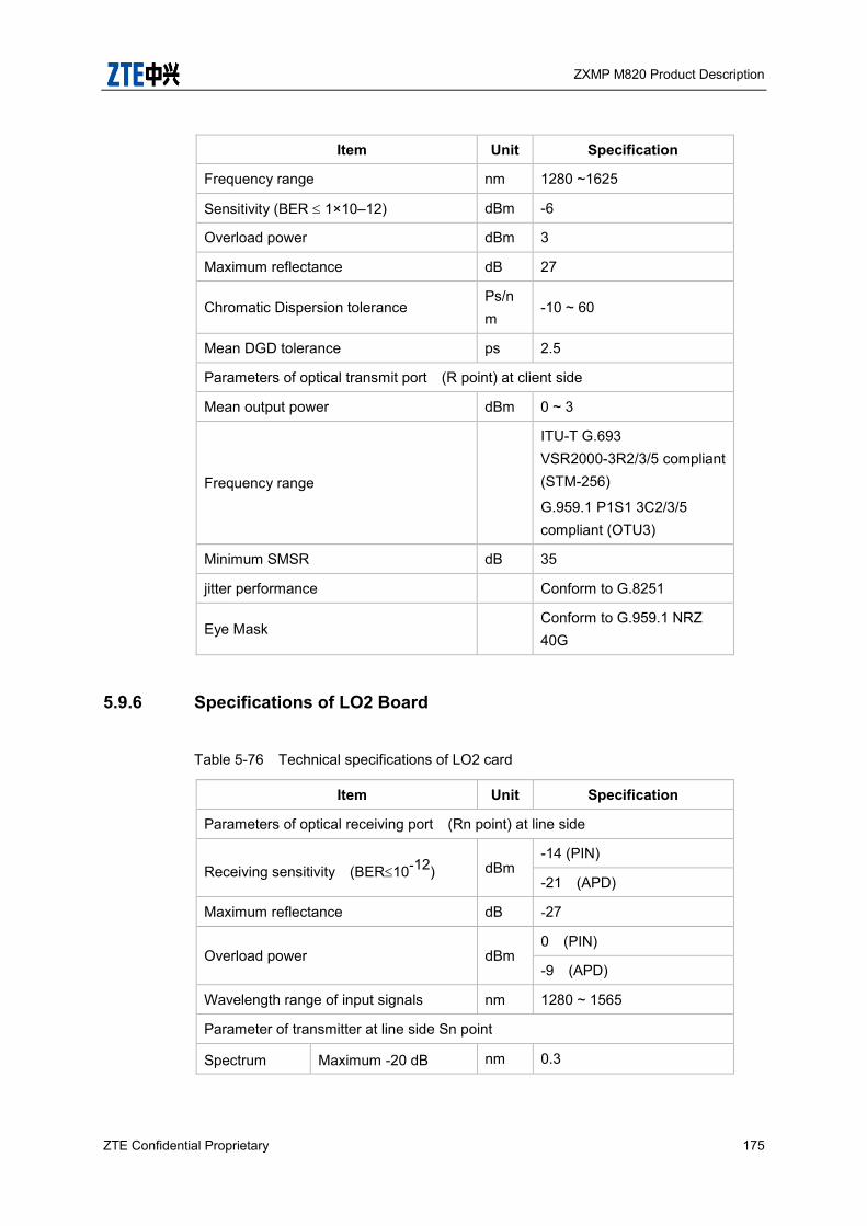
ZXMP M820 Product Description
ZTE Confidential Proprietary 175
Item Unit Specification
Frequency range nm 1280 ~1625
Sensitivity (BER 1×10–12) dBm -6
Overload power dBm 3
Maximum reflectance dB 27
Chromatic Dispersion tolerance Ps/nm
-10 ~ 60
Mean DGD tolerance ps 2.5
Parameters of optical transmit port (R point) at client side
Mean output power dBm 0 ~ 3
Frequency range
ITU-T G.693 VSR2000-3R2/3/5 compliant (STM-256)
G.959.1 P1S1 3C2/3/5 compliant (OTU3)
Minimum SMSR dB 35
jitter performance Conform to G.8251
Eye Mask Conform to G.959.1 NRZ 40G
5.9.6 Specifications of LO2 Board
Table 5-76 Technical specifications of LO2 card
Item Unit Specification
Parameters of optical receiving port (Rn point) at line side
Receiving sensitivity (BER10-12) dBm -14 (PIN)
-21 (APD)
Maximum reflectance dB -27
Overload power dBm 0 (PIN)
-9 (APD)
Wavelength range of input signals nm 1280 ~ 1565
Parameter of transmitter at line side Sn point
Spectrum Maximum -20 dB nm 0.3

ZXMP M820 Product Description
176 ZTE Confidential Proprietary
Item Unit Specification
characteristics spectrum width
Minimum side mode compression ratio (SMCR)
dB 35
Central frequency
Central frequency THz 192.10~196.05
Central frequency offset
GHz ≤ 12.5 (spacing: 100 GHz)
≤ 5 (spacing: 50 GHz)
Average optical transmit power dBm -5 ~ -1
Minimum extinction ratio dB 10
Dispersion tolerance ps/nm 800
Eye diagram template - Comply with ITU-T G.691
5.9.7 Specifications of LO2B Board
Table 5-77 Technical specifications of LO2B card
Item Unit Specification
Parameters of optical receiving port (Rn point) at line side
Receiving sensitivity (BER10-12) dBm -15
Maximum reflectance dB -27
Overload power dBm -0.5
Wavelength range of input signals nm 1290 ~ 1565
Parameter of transmitter at line side Sn point
Spectrum characteristics
Maximum -20 dB spectrum width
nm 0.3
Minimum side mode compression ratio (SMCR)
dB 35
Central frequency
Central frequency THz 192.10~196.05
Central frequency GHz ≤ 12.5 (spacing: 100
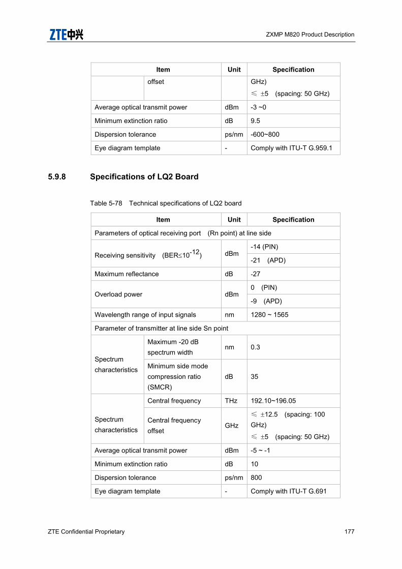
ZXMP M820 Product Description
ZTE Confidential Proprietary 177
Item Unit Specification
offset GHz)
≤ 5 (spacing: 50 GHz)
Average optical transmit power dBm -3 ~0
Minimum extinction ratio dB 9.5
Dispersion tolerance ps/nm -600~800
Eye diagram template - Comply with ITU-T G.959.1
5.9.8 Specifications of LQ2 Board
Table 5-78 Technical specifications of LQ2 board
Item Unit Specification
Parameters of optical receiving port (Rn point) at line side
Receiving sensitivity (BER10-12) dBm -14 (PIN)
-21 (APD)
Maximum reflectance dB -27
Overload power dBm 0 (PIN)
-9 (APD)
Wavelength range of input signals nm 1280 ~ 1565
Parameter of transmitter at line side Sn point
Spectrum characteristics
Maximum -20 dB spectrum width
nm 0.3
Minimum side mode compression ratio (SMCR)
dB 35
Spectrum characteristics
Central frequency THz 192.10~196.05
Central frequency offset
GHz ≤ 12.5 (spacing: 100 GHz)
≤ 5 (spacing: 50 GHz)
Average optical transmit power dBm -5 ~ -1
Minimum extinction ratio dB 10
Dispersion tolerance ps/nm 800
Eye diagram template - Comply with ITU-T G.691
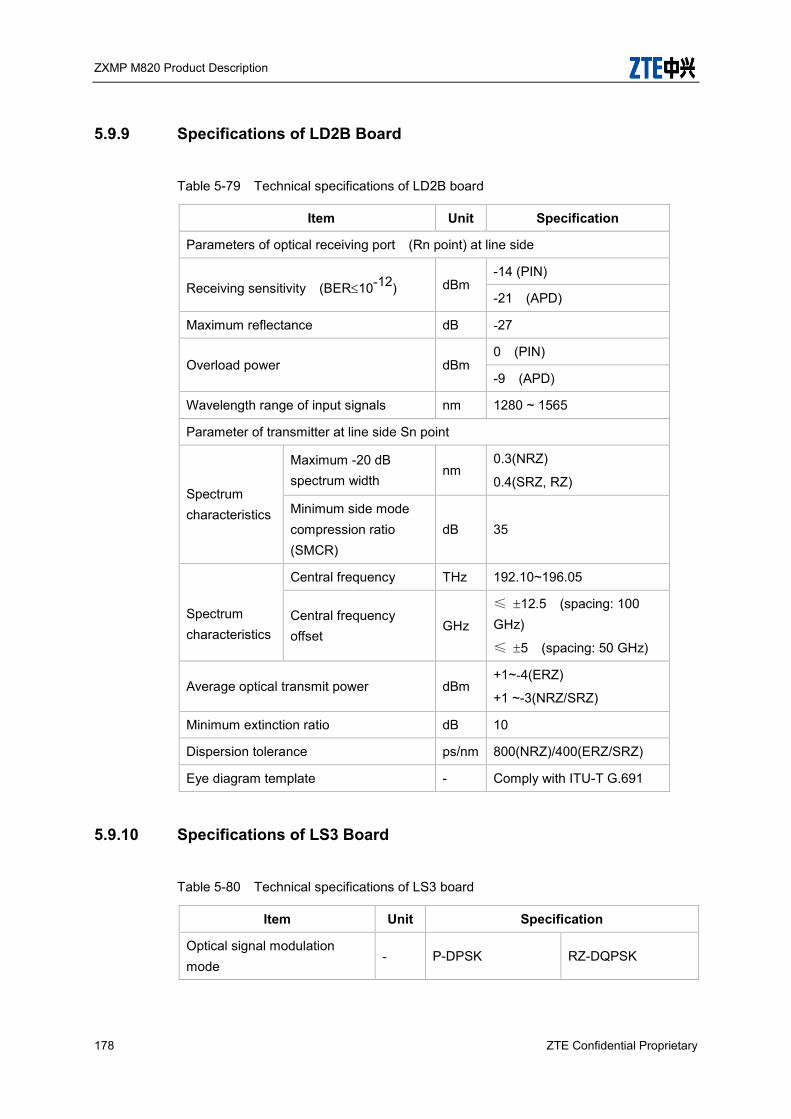
ZXMP M820 Product Description
178 ZTE Confidential Proprietary
5.9.9 Specifications of LD2B Board
Table 5-79 Technical specifications of LD2B board
Item Unit Specification
Parameters of optical receiving port (Rn point) at line side
Receiving sensitivity (BER10-12) dBm -14 (PIN)
-21 (APD)
Maximum reflectance dB -27
Overload power dBm 0 (PIN)
-9 (APD)
Wavelength range of input signals nm 1280 ~ 1565
Parameter of transmitter at line side Sn point
Spectrum characteristics
Maximum -20 dB spectrum width
nm 0.3(NRZ)
0.4(SRZ, RZ)
Minimum side mode compression ratio (SMCR)
dB 35
Spectrum characteristics
Central frequency THz 192.10~196.05
Central frequency offset
GHz
≤ 12.5 (spacing: 100 GHz)
≤ 5 (spacing: 50 GHz)
Average optical transmit power dBm +1~-4(ERZ)
+1 ~-3(NRZ/SRZ)
Minimum extinction ratio dB 10
Dispersion tolerance ps/nm 800(NRZ)/400(ERZ/SRZ)
Eye diagram template - Comply with ITU-T G.691
5.9.10 Specifications of LS3 Board
Table 5-80 Technical specifications of LS3 board
Item Unit Specification
Optical signal modulation mode
- P-DPSK RZ-DQPSK

ZXMP M820 Product Description
ZTE Confidential Proprietary 179
Item Unit Specification
Bit rate Gbps 43.018 43.018
Parameters of optical receive port at line side (Rn point)
Frequency range THz
192.10~196.05(C band)
191.30~196.075 ( CE band)
192.10~196.05(C band)
Sensitivity (BER=1×10–12) dBm -18 -18
Minimum overload power (BER=1×10–12)
dBm 0 0
Receiver reflectance dB <-27 <-27
Dispersion tolerance (including TDC)
ps/nm
-700~+700 -700~+700
Jitter transfer characteristics - Complies with G.8251
Complies with G.8251
FEC gain dB >8(AFEC) >8(AFEC)
Parameters of optical transmit port at line side (Sn point)
Nominal central frequency
THz
192.10~196.05(C band)
191.30~196.075 ( CE band)
186.95~190.90(L band)
192.10~196.05(C band)
191.30~196.075 ( CE band)
186.95~190.90(L band)
Channel spacing GHz 50 50
Maximum central frequency offset
GHz ±2.5 ±2.5
Mean launched power
Maximum dBm
+5 +5
Minimum -5 -10
Launched power offset dB ±1 ±1
Spectral characteristics
Maximum –20 dB bandwidth
nm 0.7 0.7
Minimum side mode compression ratio (SMCR)
dB 35 35
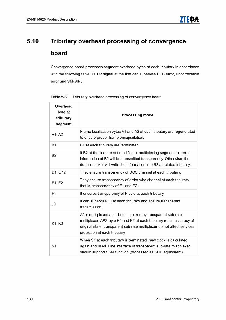
ZXMP M820 Product Description
180 ZTE Confidential Proprietary
5.10 Tributary overhead processing of convergence
board
Convergence board processes segment overhead bytes at each tributary in accordance
with the following table. OTU2 signal at the line can supervise FEC error, uncorrectable
error and SM-BIP8.
Table 5-81 Tributary overhead processing of convergence board
Overhead byte at
tributary segment
Processing mode
A1, A2 Frame localization bytes A1 and A2 at each tributary are regenerated to ensure proper frame encapsulation.
B1 B1 at each tributary are terminated.
B2
If B2 at the line are not modified at multiplexing segment, bit error information of B2 will be transmitted transparently. Otherwise, the de-multiplexer will write the information into B2 at related tributary.
D1~D12 They ensure transparency of DCC channel at each tributary.
E1,E2 They ensure transparency of order wire channel at each tributary, that is, transparency of E1 and E2.
F1 It ensures transparency of F byte at each tributary.
J0 It can supervise J0 at each tributary and ensure transparent transmission.
K1,K2
After multiplexed and de-multiplexed by transparent sub-rate multiplexer, APS byte K1 and K2 at each tributary retain accuracy of original state, transparent sub-rate multiplexer do not affect services protection at each tributary.
S1 When S1 at each tributary is terminated, new clock is calculated again and used. Line interface of transparent sub-rate multiplexer should support SSM function (processed as SDH equipment).

ZXMP M820 Product Description
ZTE Confidential Proprietary 181
5.11 OS Channel (SOSC) Unit Specifications
The SOSC interface technical specifications of ZXMP M820 are listed in Table 5-82
Table 5-82 Technical specifications of SOSC Board
Item Unit Specification
Optical signal type 100BASE-FX
Operating wavelength nm 1510±10
Signal code 4B/5B
Supervision rate 100
Signal transmission power dBm -5 to 0 -1 to 6 ≥+4
Minimum receiving sensitivity dBm -34 -35 -43
5.12 Supervision Unit Specifications
In ZXMP M820 system, each DWDM TM, de-multiplexer and optical amplifier provide
service supervision interface SC/PC to supervise active optical channel in real time
without disconnecting services. Optical power difference between supervision interface
and active optical channel can be found in the following Table 5-83
Table 5-83 Technical specifications of supervision unit at boards
Board Division ratio at input supervision interface
Division ratio at output supervision interface
OMU None 2.5%
ODU 2.5% None
OCI 0.5% 2.5%
OBM 2.5% 0.5%
OA None 0.1% for 24dBm output OA, and 0.5% for others
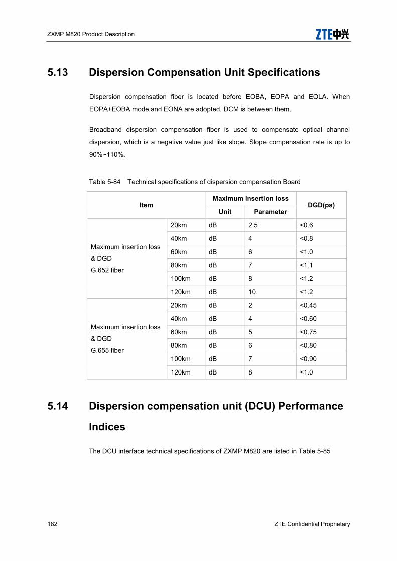
ZXMP M820 Product Description
182 ZTE Confidential Proprietary
5.13 Dispersion Compensation Unit Specifications
Dispersion compensation fiber is located before EOBA, EOPA and EOLA. When
EOPA+EOBA mode and EONA are adopted, DCM is between them.
Broadband dispersion compensation fiber is used to compensate optical channel
dispersion, which is a negative value just like slope. Slope compensation rate is up to
90%~110%.
Table 5-84 Technical specifications of dispersion compensation Board
Item Maximum insertion loss
DGD(ps) Unit Parameter
Maximum insertion loss
& DGD
G.652 fiber
20km dB 2.5 <0.6
40km dB 4 <0.8
60km dB 6 <1.0
80km dB 7 <1.1
100km dB 8 <1.2
120km dB 10 <1.2
Maximum insertion loss
& DGD
G.655 fiber
20km dB 2 <0.45
40km dB 4 <0.60
60km dB 5 <0.75
80km dB 6 <0.80
100km dB 7 <0.90
120km dB 8 <1.0
5.14 Dispersion compensation unit (DCU) Performance
Indices
The DCU interface technical specifications of ZXMP M820 are listed in Table 5-85

ZXMP M820 Product Description
ZTE Confidential Proprietary 183
Table 5-85 Main technical specifications of DCU Board
Item Unit Specification
Optical input power dBm -14 ~ +2
Dispersion adjustment range GHz +/- 700
5.15 Physical Performance
5.15.1 Structure Indices
The dimensions and weight of ZXMP M820 are shown in Table 5-86 and Table 5-87
Table 5-86 Dimensions and Weight of ZXMP M820
Components Dimensions Weight
(kg)
Unified cabinets of ZTE transmission equipment
2,000 mm (H) × 600 mm (W) × 300 mm (D) 58.50
2,200 mm (H) × 600 mm (W) × 300 mm (D) 64.50
2,600 mm (H) × 600 mm (W) × 300 mm (D) 76.00
sub-rack ( 21 inch ) 422 mm (H) × 533mm (W) × 286 mm (D) 12.50
sub-rack ( 19 inch ) 422 mm (H) × 473mm (W) × 286 mm (D) 11.20
CX4 447 mm (H) x 535 mm (W) x 275 mm (D) 18
CX20 447 mm (H) x 535 mm (W) x 275 mm (D) 18
CX22 447 mm (H) x 535 mm (W) x 275 mm (D) 18
Power supply distribution box
88.1 (height) × 535 (width) × 258 (depth) 3.8
ODF sub-rack 88 mm (H) × 482.6 mm (W) × 269.5 mm (D) 6.50
DCM chassis 47 mm (H) × 533 mm (W) × 286.5 mm (D) 5.60
Conversion bracket 29.6mm (H) × 345.6mm (W) 0.30
Fan unit 30 mm (H) × 122.9 mm(W) × 276.8mm(D) 0.68
Full-height board PCB:320 mm (W) × 210 mm (D)
Front panel: 345.6 mm (H) × 29.8 mm (W) --
Compact board PCB:152 mm (W) × 210 mm (D) --

ZXMP M820 Product Description
184 ZTE Confidential Proprietary
Components Dimensions Weight
(kg)
Front panel: 155.6 mm (H) × 25.1 mm (W)
Note: The cabinet weight refers to the empty cabinet.
Table 5-87 ZXMP M820 Board Weight
Board ID Board Description Weight (kg)
SNP Compact Node Process Board 0.60
SCC Compact Communication Control Board
0.47
CCP Subrack Management Board 0.7
FCC Fan Board 3.6
PWD Power Supply Board 1.05
SOSC Compact Optical Supervision
Channel Board 0.60
SOSCB Optical supervision channel board for Fast Ethernet
0.5
TIS Time interface supply card 0.5
XCA Switching Board 1.85
SOGMD Compact Optical Group
Mux/DeMux Board 0.60
SOAD1
Compact Optical
Adding/Dropping Board of 1
Wavelength
0.60
SOAD2
Compact Optical
Adding/Dropping Board of 2
Wavelength
0.60
SOAD4
Compact Optical
Adding/Dropping Board of 4
Wavelength
0.60
SOP Compact Optical Protection
Board 0.60
SOPCS Compact Optical Protection 0.60
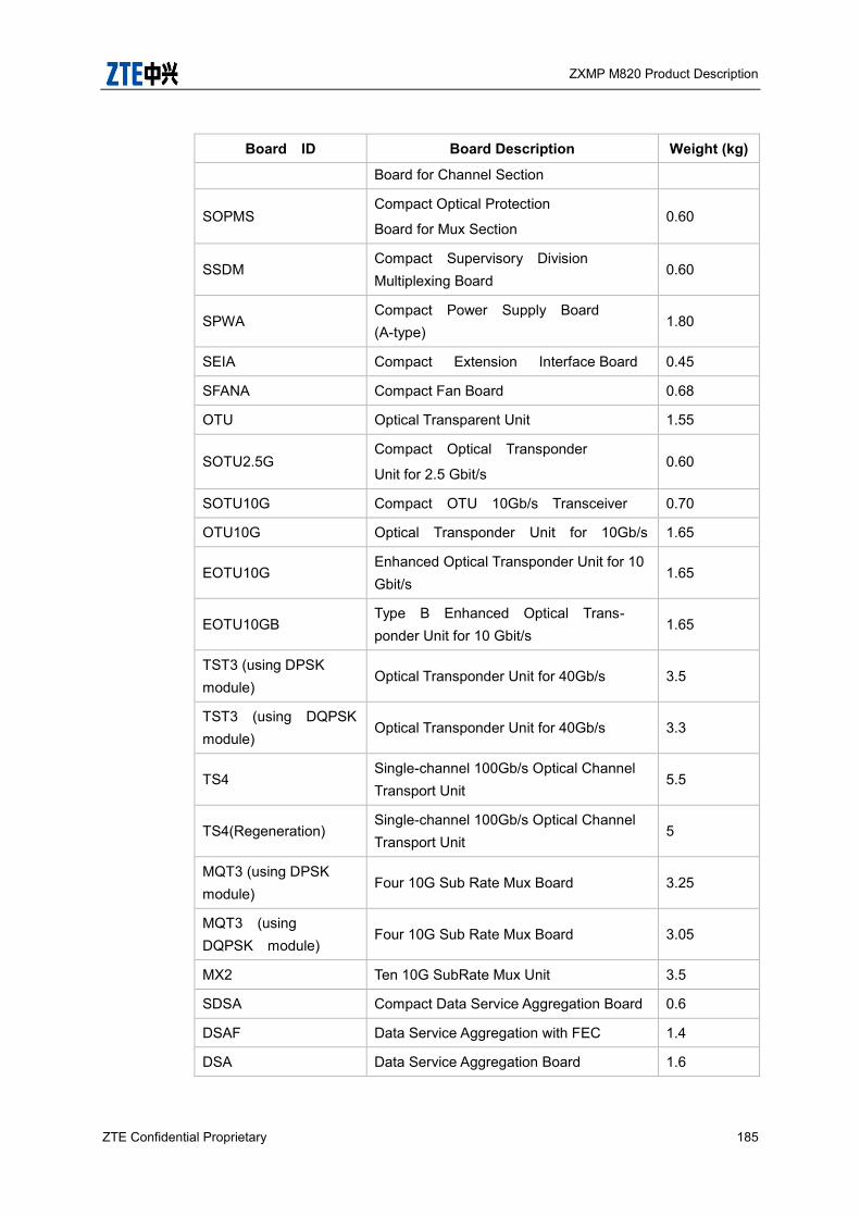
ZXMP M820 Product Description
ZTE Confidential Proprietary 185
Board ID Board Description Weight (kg)
Board for Channel Section
SOPMS Compact Optical Protection
Board for Mux Section 0.60
SSDM Compact Supervisory Division Multiplexing Board
0.60
SPWA Compact Power Supply Board (A-type)
1.80
SEIA Compact Extension Interface Board 0.45
SFANA Compact Fan Board 0.68
OTU Optical Transparent Unit 1.55
SOTU2.5G Compact Optical Transponder
Unit for 2.5 Gbit/s 0.60
SOTU10G Compact OTU 10Gb/s Transceiver 0.70
OTU10G Optical Transponder Unit for 10Gb/s 1.65
EOTU10G Enhanced Optical Transponder Unit for 10 Gbit/s
1.65
EOTU10GB Type B Enhanced Optical Trans- ponder Unit for 10 Gbit/s
1.65
TST3 (using DPSK module)
Optical Transponder Unit for 40Gb/s 3.5
TST3 (using DQPSK module)
Optical Transponder Unit for 40Gb/s 3.3
TS4 Single-channel 100Gb/s Optical Channel Transport Unit
5.5
TS4(Regeneration) Single-channel 100Gb/s Optical Channel Transport Unit
5
MQT3 (using DPSK module)
Four 10G Sub Rate Mux Board 3.25
MQT3 (using DQPSK module)
Four 10G Sub Rate Mux Board 3.05
MX2 Ten 10G SubRate Mux Unit 3.5
SDSA Compact Data Service Aggregation Board 0.6
DSAF Data Service Aggregation with FEC 1.4
DSA Data Service Aggregation Board 1.6

ZXMP M820 Product Description
186 ZTE Confidential Proprietary
Board ID Board Description Weight (kg)
GEMF Gigabit Ethernet Mux Board with FEC
1.50
GEM2 Two Gigabit Ethernet Mux Board 1.50
GEM8 Eight Gigabit Ethernet Mux Board 2.05
FCA FC service Access unit 1.5
MOM2 Eight GE/FC Muxponder 1.5
SRM42 Four 622 M/155 M SubRate Mux Board
1.25
SRM41 Four 2.5 G SubRate Mux Board 1.25
ASMA Type A Convergence Switching Board
0.6
CS3 Client board for Single OTU3 1.4
CD3 Client board for Double OTU3 2.325
CO2 Client board for 8*OTU2 2.1
CQ2 Client board for 4*OTU2 1.8
CH1 Client board for 16*GE or 8*OTU1 1.075
LS3(2 slots) Line board for single OTU3( 2 slots) 3.25
LS3(DPSK)(1 slot) Line board for single OTU3 (1slot) 2.225
LS3(DQPSK)(1 slot) Line board for single OTU3 (1slot) 2.32
LO2 Line board for 8*OTU2 2.1
LQ2 Line board for 4*OTU2 1.8
LD2B Line board for 2*OTU2 1.95
TD2C Transponder of 2 ports 10Gb/s 0.7
MQA2 Muxponder of 4 ports any rate to OTU2 0.6
MQA1 Muxponder of 4 ports any rate to OTU1 0.6
MJA Muxponder of 6 ports any rate to main board
0.5
EOBA Enhanced Optical Booster Amplifier 1.80
EOPA Enhanced Optical Pre-Amplifier 1.80
EOLA Enhanced Optical Line Amplifier 1.80
EONA Enhanced Optical Node Amplifier 2.00
SEOBA Enhanced Optical Booster Amplifier 0.60
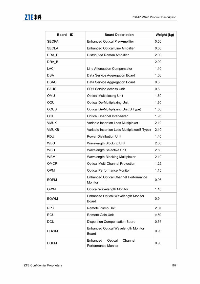
ZXMP M820 Product Description
ZTE Confidential Proprietary 187
Board ID Board Description Weight (kg)
SEOPA Enhanced Optical Pre-Amplifier 0.60
SEOLA Enhanced Optical Line Amplifier 0.60
DRA_P Distributed Raman Amplifier 2.00
DRA_B 2.00
LAC Line Attenuation Compensator 1.10
DSA Data Service Aggregation Board 1.60
DSAC Data Service Aggregation Board 0.6
SAUC SDH Service Access Unit 0.6
OMU Optical Multiplexing Unit 1.60
ODU Optical De-Multiplexing Unit 1.60
ODUB Optical De-Multiplexing Unit(B Type) 1.60
OCI Optical Channel Interleaver 1.95
VMUX Variable Insertion Loss Multiplexer 2.10
VMUXB Variable Insertion Loss Multiplexer(B Type) 2.10
PDU Power Distribution Unit 1.40
WBU Wavelength Blocking Unit 2.60
WSU Wavelength Selective Unit 2.60
WBM Wavelength Blocking Multiplexer 2.10
OMCP Optical Multi-Channel Protection 1.25
OPM Optical Performance Monitor 1.15
EOPM Enhanced Optical Channel Performance Monitor
0.96
OWM Optical Wavelength Monitor 1.10
EOWM Enhanced Optical Wavelength Monitor Board
0.9
RPU Remote Pump Unit 2.00
RGU Remote Gain Unit 0.50
DCU Dispersion Compensation Board 0.55
EOWM Enhanced Optical Wavelength Monitor Board
0.90
EOPM Enhanced Optical Channel Performance Monitor
0.96
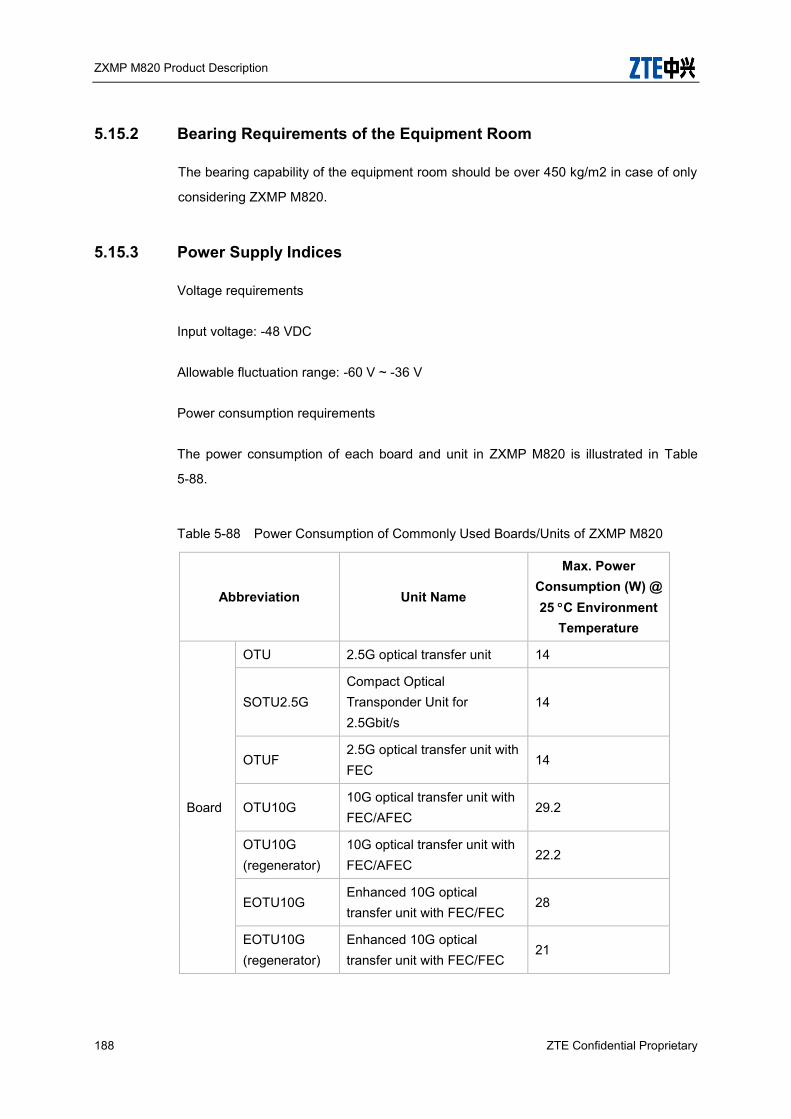
ZXMP M820 Product Description
188 ZTE Confidential Proprietary
5.15.2 Bearing Requirements of the Equipment Room
The bearing capability of the equipment room should be over 450 kg/m2 in case of only
considering ZXMP M820.
5.15.3 Power Supply Indices
Voltage requirements
Input voltage: -48 VDC
Allowable fluctuation range: -60 V ~ -36 V
Power consumption requirements
The power consumption of each board and unit in ZXMP M820 is illustrated in Table
5-88.
Table 5-88 Power Consumption of Commonly Used Boards/Units of ZXMP M820
Abbreviation Unit Name
Max. Power Consumption (W) @ 25 C Environment
Temperature
Board
OTU 2.5G optical transfer unit 14
SOTU2.5G Compact Optical Transponder Unit for 2.5Gbit/s
14
OTUF 2.5G optical transfer unit with FEC
14
OTU10G 10G optical transfer unit with FEC/AFEC
29.2
OTU10G (regenerator)
10G optical transfer unit with FEC/AFEC
22.2
EOTU10G Enhanced 10G optical transfer unit with FEC/FEC
28
EOTU10G (regenerator)
Enhanced 10G optical transfer unit with FEC/FEC
21

ZXMP M820 Product Description
ZTE Confidential Proprietary 189
Abbreviation Unit Name
Max. Power Consumption (W) @ 25 C Environment
Temperature
EOTU10GB Type B Enhanced OTU 10Gbit/s Transceiver
28
SOTU10G Semi 10G optical transfer unit with FEC/FEC
25
TST3 40G optical transfer unit with FEC/AFEC
90
TST3 (regenerator)
40G optical transfer unit with FEC/AFEC
79
MQT3 Four 10G SubRate Mux Board
120
TS4 Single-channel 100Gb/s Optical Channel Transport Board
190
MX2
(no SFP++)
Ten 10G Sub Rate Mux Board
185
MX2
(with SFP++) Ten 10G Sub Rate Mux Board
200
SRM41 Four 2.5G SubRate Mux Board
33
SRM42 Four 622M/155M SubRate Mux Board
20
SDSA Compact Data Service Aggregation Board
25
DSAF Data Service Aggregation
with FEC 22
DSA Data Service Aggregation
Board 25
GEM2 Dual-channel gigabit Ethernet convergence board
13
GEMF Dual-channel gigabit Ethernet convergence board with FEC
18
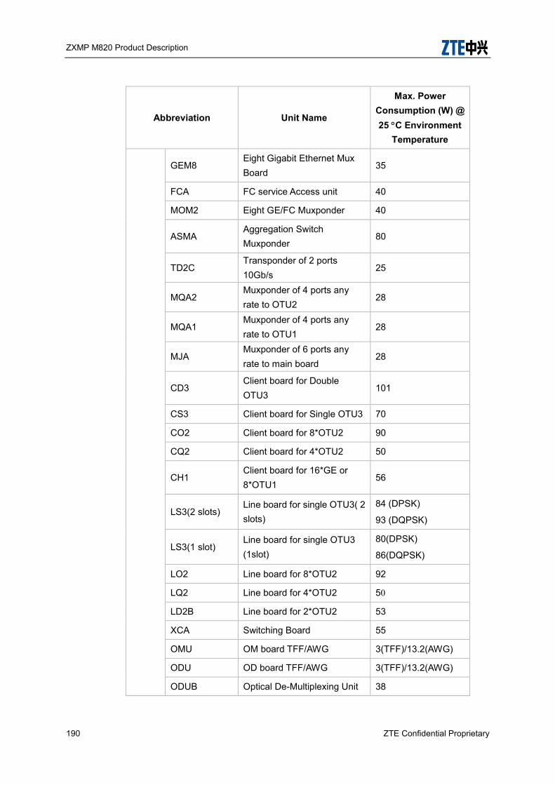
ZXMP M820 Product Description
190 ZTE Confidential Proprietary
Abbreviation Unit Name
Max. Power Consumption (W) @ 25 C Environment
Temperature
GEM8 Eight Gigabit Ethernet Mux Board
35
FCA FC service Access unit 40
MOM2 Eight GE/FC Muxponder 40
ASMA Aggregation Switch Muxponder
80
TD2C Transponder of 2 ports 10Gb/s
25
MQA2 Muxponder of 4 ports any rate to OTU2
28
MQA1 Muxponder of 4 ports any rate to OTU1
28
MJA Muxponder of 6 ports any rate to main board
28
CD3 Client board for Double OTU3
101
CS3 Client board for Single OTU3 70
CO2 Client board for 8*OTU2 90
CQ2 Client board for 4*OTU2 50
CH1 Client board for 16*GE or 8*OTU1
56
LS3(2 slots) Line board for single OTU3( 2 slots)
84 (DPSK)
93 (DQPSK)
LS3(1 slot) Line board for single OTU3 (1slot)
80(DPSK)
86(DQPSK)
LO2 Line board for 8*OTU2 92
LQ2 Line board for 4*OTU2 50
LD2B Line board for 2*OTU2 53
XCA Switching Board 55
OMU OM board TFF/AWG 3(TFF)/13.2(AWG)
ODU OD board TFF/AWG 3(TFF)/13.2(AWG)
ODUB Optical De-Multiplexing Unit 38

ZXMP M820 Product Description
ZTE Confidential Proprietary 191
Abbreviation Unit Name
Max. Power Consumption (W) @ 25 C Environment
Temperature
(B Type)
VMUX Variable insertion loss Multiplexer
30
VMUXB Variable Insertion Loss Multiplexer (B Type)
30
OCI Optical multiplex/demultiplex interleaver
3
OBM Optical broadband multiplexer
3
SOAD1 Compact Optical Add/
Drop Board of 1/2/4 Wave
length
4
SOAD2 4
SOAD4 5
WBU Wavelength Blocking Unit 15
WSU Wavelength Selective Unit 15
WBM Wavelength Blocking Multiplexing
32
PDU Power Distribution Unit 3
EOBA
Enhanced Optical power amplifier
20
EOBAS 14.5
EOBAH2424 30
EOBAH2726 40
EOPA Enhanced Optical preamplifier
11
EOLA Enhanced Optical line amplifier
14.5
EONA Enhanced Optical node amplifier
25
SEOBA Enhanced Optical Booster
Amplifier 14
SEOPA Enhanced Optical PreAmplifier
11

ZXMP M820 Product Description
192 ZTE Confidential Proprietary
Abbreviation Unit Name
Max. Power Consumption (W) @ 25 C Environment
Temperature
SEOLA Enhanced Optical Line Amplifier
14
RPU Remote Pump Unit 80
RGU Remote Gain Unit 0
DRA Distributed Raman amplifier 35
SOP Optical protection board 5
SOPCS Compact Optical Protection
Board for Channel Section 3
SOPMS Compact Optical Protection
Board for Mux Section 3
OMCP Optical Protect for Mux Section
5
OPM Optical performance monitoring board
5
OWM Optical Wavelength
Monitor 3
EOPM Enhanced Optical Channel
Performance Monitor 10
EOWM
Enhanced Optical
Wavelength Monitor
Board
10
SOSC Optical supervision channel board
12
SOSCB Optical supervision channel board for Fast Ethernet
18
TIS Time interface supply card 15
CCP Subrack Management Board 18
FCC Fan Board 67
SNP Net control processor 10
SCC Communication Control
Board 10

ZXMP M820 Product Description
ZTE Confidential Proprietary 193
Abbreviation Unit Name
Max. Power Consumption (W) @ 25 C Environment
Temperature
SEIA Compact Extension Interface
Board 5
SDMT Transmitter supervisory add/drop multiplexer board
4
SDMR Receiver supervisory add/drop multiplexer board
4
LACG Line attenuation control board (generator)
3
LACT Line attenuation control board (terminal)
3
SEI Extension Interface Board 5
SPWA Power Board (A-type) 28
PWD Power Supply Board 5.8
SFAN Compact Fan Board 10
Sub-rack
- Master Sub-rack(NX) 733
Slave Sub-rack(NX) 721
Note: The power values of the sub-rack is for full configuration of 10G OTU (SOTU 10G).
The power consumption in the table is the maximum value at normal temperature.
5.16 Environment Conditions
5.16.1 Grounding Requirements
Internal grounding requirements of the system
The board shielding plate is grounded via the panel to the case, and there is no
electronic connection inside a board.
The cabinet and sub-rack case are connected to the protective ground.
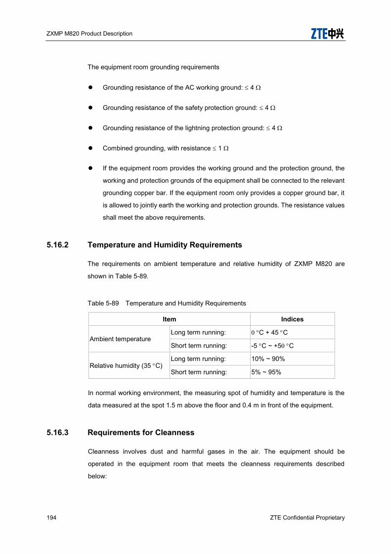
ZXMP M820 Product Description
194 ZTE Confidential Proprietary
The equipment room grounding requirements
Grounding resistance of the AC working ground: 4
Grounding resistance of the safety protection ground: 4
Grounding resistance of the lightning protection ground: 4
Combined grounding, with resistance 1
If the equipment room provides the working ground and the protection ground, the
working and protection grounds of the equipment shall be connected to the relevant
grounding copper bar. If the equipment room only provides a copper ground bar, it
is allowed to jointly earth the working and protection grounds. The resistance values
shall meet the above requirements.
5.16.2 Temperature and Humidity Requirements
The requirements on ambient temperature and relative humidity of ZXMP M820 are
shown in Table 5-89.
Table 5-89 Temperature and Humidity Requirements
Item Indices
Ambient temperature Long term running: 0 C + 45 C
Short term running: -5 C ~ +50 C
Relative humidity (35 C) Long term running: 10% ~ 90%
Short term running: 5% ~ 95%
In normal working environment, the measuring spot of humidity and temperature is the
data measured at the spot 1.5 m above the floor and 0.4 m in front of the equipment.
5.16.3 Requirements for Cleanness
Cleanness involves dust and harmful gases in the air. The equipment should be
operated in the equipment room that meets the cleanness requirements described
below:
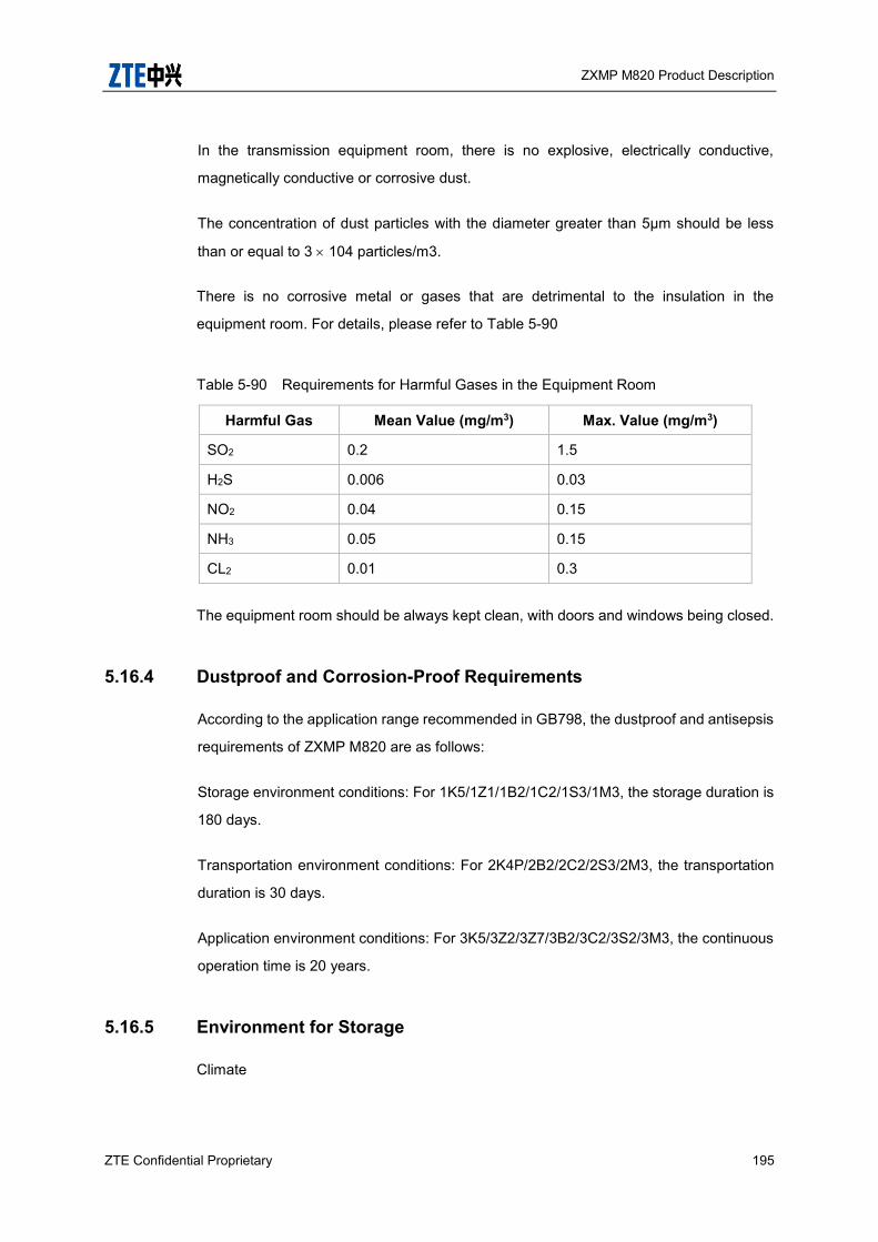
ZXMP M820 Product Description
ZTE Confidential Proprietary 195
In the transmission equipment room, there is no explosive, electrically conductive,
magnetically conductive or corrosive dust.
The concentration of dust particles with the diameter greater than 5µm should be less
than or equal to 3 104 particles/m3.
There is no corrosive metal or gases that are detrimental to the insulation in the
equipment room. For details, please refer to Table 5-90
Table 5-90 Requirements for Harmful Gases in the Equipment Room
Harmful Gas Mean Value (mg/m3) Max. Value (mg/m3)
SO2 0.2 1.5
H2S 0.006 0.03
NO2 0.04 0.15
NH3 0.05 0.15
CL2 0.01 0.3
The equipment room should be always kept clean, with doors and windows being closed.
5.16.4 Dustproof and Corrosion-Proof Requirements
According to the application range recommended in GB798, the dustproof and antisepsis
requirements of ZXMP M820 are as follows:
Storage environment conditions: For 1K5/1Z1/1B2/1C2/1S3/1M3, the storage duration is
180 days.
Transportation environment conditions: For 2K4P/2B2/2C2/2S3/2M3, the transportation
duration is 30 days.
Application environment conditions: For 3K5/3Z2/3Z7/3B2/3C2/3S2/3M3, the continuous
operation time is 20 years.
5.16.5 Environment for Storage
Climate

ZXMP M820 Product Description
196 ZTE Confidential Proprietary
Table 5-91 Climate requirement
Item Range
Altitude < 4000m
Air pressure 70 ~ 106kPa
Temperature -40℃~ +70℃
Temperature change rate < 1℃/min
Relative humidity 5% ~ 100%
Solar radiation 1120W/s²
Air speed < 20m/s²
Mechanical stress
Table 5-92 Requirements for mechanical stress
Item unit value
Acceleration m/S2 0.1
Frequency range Hz 5~100, 100~5
direction X,Y,Z
duration Min 90
The earthquake-proof performance detection reaches the eight-level intensity
5.16.6 Environment for Transportation
Climate
Table 5-93 Climate requirement
Item Range
Altitude < 4000m
Air pressure 70 ~ 106kPa
Temperature -40℃~ +70℃
Temperature change rate < 1 ℃/min
Relative humidity 5% ~ 100%
Solar radiation < 1120W/s²
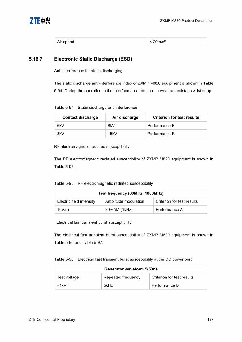
ZXMP M820 Product Description
ZTE Confidential Proprietary 197
Air speed < 20m/s²
5.16.7 Electronic Static Discharge (ESD)
Anti-interference for static discharging
The static discharge anti-interference index of ZXMP M820 equipment is shown in Table
5-94. During the operation in the interface area, be sure to wear an antistatic wrist strap.
Table 5-94 Static discharge anti-interference
Contact discharge Air discharge Criterion for test results
6kV 8kV Performance B
8kV 15kV Performance R
RF electromagnetic radiated susceptibility
The RF electromagnetic radiated susceptibility of ZXMP M820 equipment is shown in
Table 5-95.
Table 5-95 RF electromagnetic radiated susceptibility
Test frequency (80MHz~1000MHz)
Electric field intensity Amplitude modulation Criterion for test results
10V/m 80%AM (1kHz) Performance A
Electrical fast transient burst susceptibility
The electrical fast transient burst susceptibility of ZXMP M820 equipment is shown in
Table 5-96 and Table 5-97.
Table 5-96 Electrical fast transient burst susceptibility at the DC power port
Generator waveform 5/50ns
Test voltage Repeated frequency Criterion for test results
1kV 5kHz Performance B
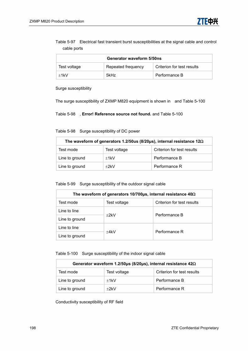
ZXMP M820 Product Description
198 ZTE Confidential Proprietary
Table 5-97 Electrical fast transient burst susceptibilities at the signal cable and control cable ports
Generator waveform 5/50ns
Test voltage Repeated frequency Criterion for test results
1kV 5kHz Performance B
Surge susceptibility
The surge susceptibility of ZXMP M820 equipment is shown in and Table 5-100
Table 5-98 , Error! Reference source not found. and Table 5-100
Table 5-98 Surge susceptibility of DC power
The waveform of generators 1.2/50us (8/20μs), internal resistance 12
Test mode Test voltage Criterion for test results
Line to ground 1kV Performance B
Line to ground 2kV Performance R
Table 5-99 Surge susceptibility of the outdoor signal cable
The waveform of generators 10/700µs, internal resistance 40
Test mode Test voltage Criterion for test results
Line to line 2kV Performance B
Line to ground
Line to line 4kV Performance R
Line to ground
Table 5-100 Surge susceptibility of the indoor signal cable
Generator waveform 1.2/50μs (8/20μs), internal resistance 42
Test mode Test voltage Criterion for test results
Line to ground 1kV Performance B
Line to ground 2kV Performance R
Conductivity susceptibility of RF field

ZXMP M820 Product Description
ZTE Confidential Proprietary 199
The conductivity susceptibility of RF field of ZXMP M820 equipment is shown in Table
5-101
Table 5-101 Conductivity susceptibility of RF field
Test frequency 0.15MHz ~ 80MHz
Test intensity Amplitude modulation Criterion for test results
3V 80%AM (1kHz) Performance A
Conductive emission electromagnetic interference
The conductive emission electromagnetic interference of ZXMP M820 equipment is
shown in Table 5-102
Table 5-102 Conductive emission electromagnetic interference at the direct current port
Testing frequency (MHz) Limits (dBuV)
Quasi-peak Mean value
0.02~0.15 79 --
0.15~0.5 79 66
0.5~30 73 60
Radioactive emission electromagnetic interference
The radioactive emission electromagnetic interference of the ZXMP M820 equipment is
shown in Table 5-103
Table 5-103 Radio active emission electromagnetic interference
Testing frequency (MHz) Quasi-peak demodulating limit (dBµV/m)
10m 3m
30~230 40 50
230~1000 47 57
5.16.8 Safety requirements
This product adopts the technical requirements specified in the following standard:
ZXMP M820 Product Description
200 ZTE Confidential Proprietary
IEC/EN 60950:2000 Safety of information technology equipment
Working voltage and current
Rated working voltage: -48V
Max. working voltage: -60V
Min. working voltage: -36V
Insulation classification of the equipment
The power supply of the equipment provides the SELV circuit with safe and excessively
low voltage, without self-generating dangerous voltage. It belongs to the equipment of
the class III insulation (Class III equipment).
Optical interface
The optical module of the maximum power belongs to (Class 3A). All the optical modules
shall be under strict control and certified by authorities (such as UL, TUV and NEMKO),
and comply with EN60825.
Fuse
All the fuses and power modules, including recoverable fuses, shall be certified by
authorities such as CE, UL and TUV.
Safety mark
On the package of the equipment, there are striking labels about antistatic, fragile,
waterproof, and damp-proof.
The maximum optical power satisfies the 3A safety standard. An obvious label warning
against the laser shall be pasted at the optical interface.
Cables of different colors shall be used for the power input, shielding GND and lightening
protection GND to avoid incorrect connection. Different power connectors shall use
coding keys. There shall be a power label at the power inlet.
Both the equipment and each board shall have an antistatic label.

ZXMP M820 Product Description
ZTE Confidential Proprietary 201
Grounding symbol . ” ” indicates switch-on, and” ” indicates switch-off.
Mechanical structure
In installation, four bolts are designed at the rack bottom (may also be used to adjust
balance) to fix the rack to the ground. At the rack top, the corresponding screws are
designed to fix the rack to the cabling rack. When installed in the equipment room, the
rack shall be fixed both at the top and bottom to ensure the stability and safety of the
equipment.
The corners of both the rack and sub-rack are processed to avoid hurting people.
Fire protection
The materials of the circuit boards in the equipment use the fireproof materials of the V-2
level to prevent the circuits from burning in case of failure.
The structural parts use unburnable materials with a good fireproof performance,
including surface processing materials.
With the effective heat dissipation design, it ensures that the temperature does not
exceed 70ºC to prevent heat aggregation and reduce the possibility of burning.
Safe parts passing the safety authentication (CE, UL, etc.) are used.
High temperature protection
In abnormal conditions, the temperature does not exceed 70ºC. The plastic parts,
components, wires and cables, and safety labels shall all comply with the requirements
specified in the safety standard-GB4943/EN60950.
Lightening protection
In this system, good grounding and isolation and protection of electrical interfaces are
used to prevent the dangerous voltage of lightening.
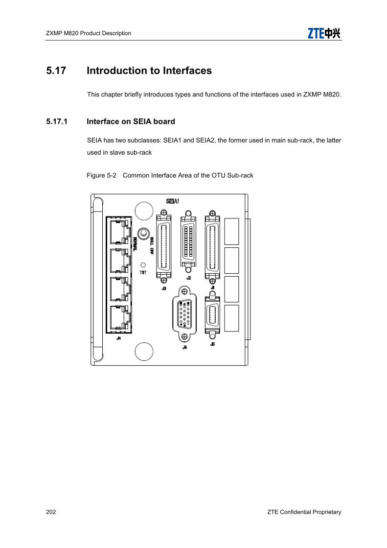
ZXMP M820 Product Description
202 ZTE Confidential Proprietary
5.17 Introduction to Interfaces
This chapter briefly introduces types and functions of the interfaces used in ZXMP M820.
5.17.1 Interface on SEIA board
SEIA has two subclasses: SEIA1 and SEIA2, the former used in main sub-rack, the latter
used in slave sub-rack
Figure 5-2 Common Interface Area of the OTU Sub-rack
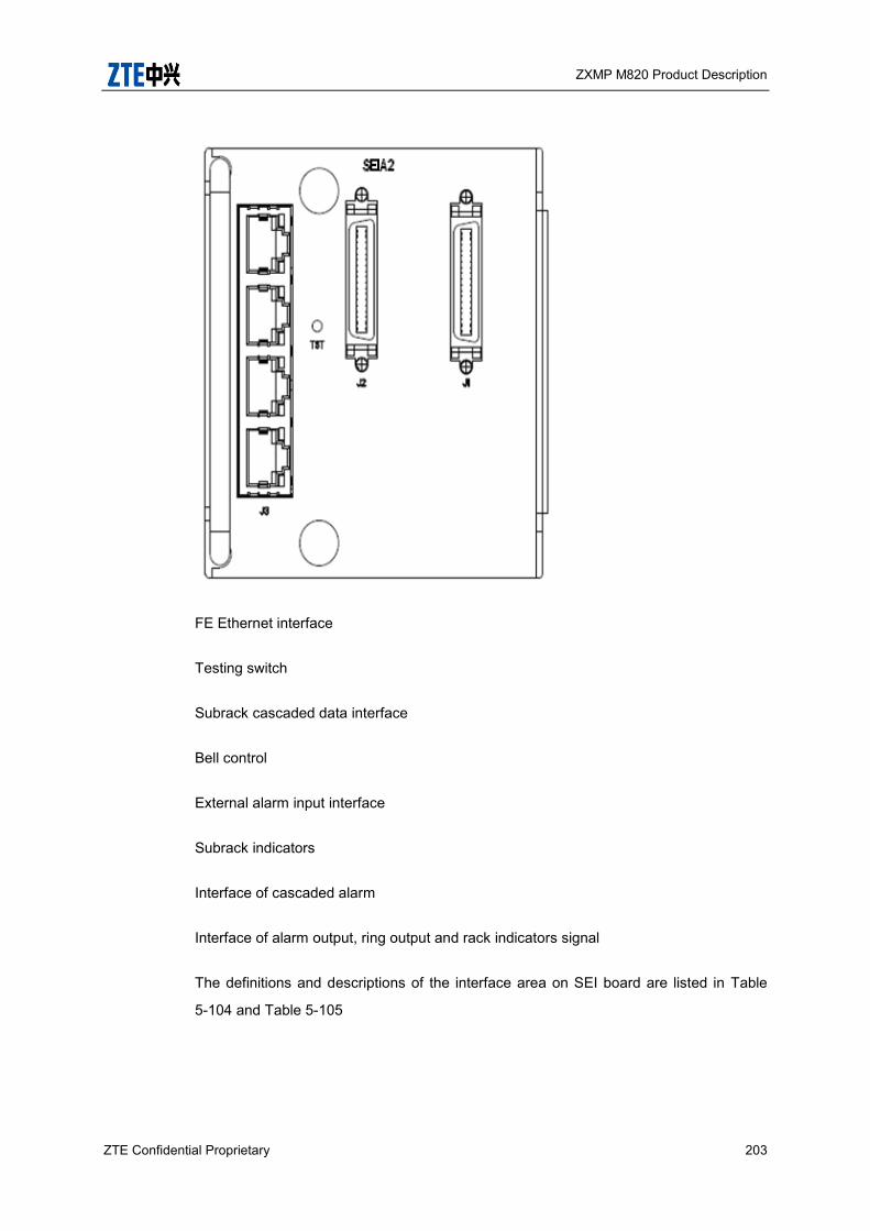
ZXMP M820 Product Description
ZTE Confidential Proprietary 203
FE Ethernet interface
Testing switch
Subrack cascaded data interface
Bell control
External alarm input interface
Subrack indicators
Interface of cascaded alarm
Interface of alarm output, ring output and rack indicators signal
The definitions and descriptions of the interface area on SEI board are listed in Table
5-104 and Table 5-105
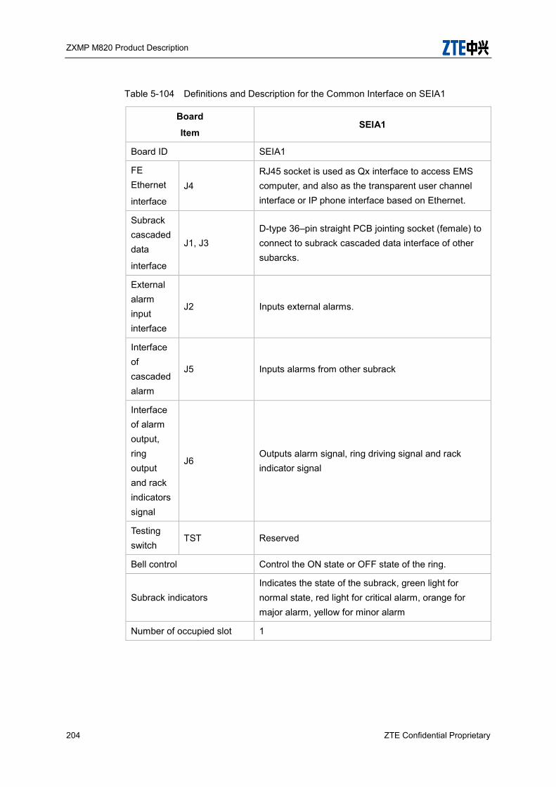
ZXMP M820 Product Description
204 ZTE Confidential Proprietary
Table 5-104 Definitions and Description for the Common Interface on SEIA1
Board
Item SEIA1
Board ID SEIA1
FE Ethernet
interface J4
RJ45 socket is used as Qx interface to access EMS computer, and also as the transparent user channel interface or IP phone interface based on Ethernet.
Subrack cascaded data
interface
J1, J3 D-type 36–pin straight PCB jointing socket (female) to connect to subrack cascaded data interface of other subarcks.
External alarm input interface
J2 Inputs external alarms.
Interface of cascaded alarm
J5 Inputs alarms from other subrack
Interface of alarm output, ring output and rack indicators signal
J6 Outputs alarm signal, ring driving signal and rack indicator signal
Testing switch
TST Reserved
Bell control Control the ON state or OFF state of the ring.
Subrack indicators Indicates the state of the subrack, green light for normal state, red light for critical alarm, orange for major alarm, yellow for minor alarm
Number of occupied slot 1
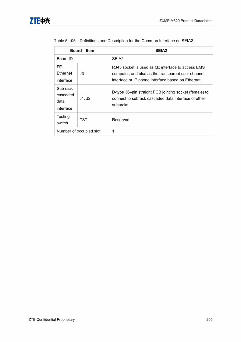
ZXMP M820 Product Description
ZTE Confidential Proprietary 205
Table 5-105 Definitions and Description for the Common Interface on SEIA2
Board Item SEIA2
Board ID SEIA2
FE Ethernet
interface J3
RJ45 socket is used as Qx interface to access EMS computer, and also as the transparent user channel interface or IP phone interface based on Ethernet.
Sub rack cascaded data
interface
J1, J2 D-type 36–pin straight PCB jointing socket (female) to connect to subrack cascaded data interface of other subarcks.
Testing switch
TST Reserved
Number of occupied slot 1

ZXMP M820 Product Description
206 ZTE Confidential Proprietary
5.17.2 Interface on SPWA board
Figure 5-3 Interfaces on the SPWA board
Terminal block
Sub rack cascaded GE interface
Sub rack cascaded GE optical interface connection indicator
Power switch
RS232 console interface
RJ-45 console interface
Indicators

ZXMP M820 Product Description
ZTE Confidential Proprietary 207
Laser warning sign
Laser level sign
The definitions and descriptions of the interface area on SPWA board are listed in Table
5-106
Table 5-106 Definitions and Description for the Common Interface on SPWA
Board
Item SPWA
Board ID SPWA
Power switch
If the switch is in the status of “ON", the external power supply is connected to the SPWA. On the other hand, if the switch is in the status of "OFF”, the connection between SPWA and the external power is cut off.
Indicator
NOM Running indicator, green
ALM Alarm indicator, red
M/S Master/slave indicator, green
0, 1, 2, 3-1, 3-2, 3-3, 3-4, 4, 5-1, 5-2, 5-3, 5-4, 6, 7, 8, 9, 10, 11, 12, 13, 14, 15, 16, 17, 18, 19, 20-1, 20-2, 21, 22-1, 22-2, 23, 24-1, 24-2, 25, 26-1, 26-2
Board internal communication indicator, green.
Sub rack cascaded GE interface
J1, J2 Connects to sub rack cascaded GE interface of other sub racks, LC/PC connector
Laser warning sign Do not look at optical interfaces directly while plugging/unplugging fiber pigtails to avoid burning eyes.
Laser class sign Indicates that the laser class of SPWA board is

ZXMP M820 Product Description
208 ZTE Confidential Proprietary
CLASS 1
Number of occupied slot 1
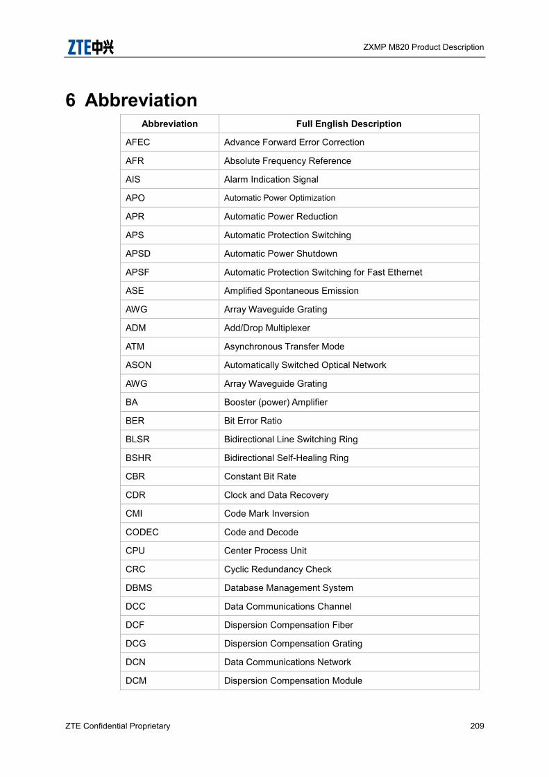
ZXMP M820 Product Description
ZTE Confidential Proprietary 209
6 Abbreviation Abbreviation Full English Description
AFEC Advance Forward Error Correction
AFR Absolute Frequency Reference
AIS Alarm Indication Signal
APO Automatic Power Optimization
APR Automatic Power Reduction
APS Automatic Protection Switching
APSD Automatic Power Shutdown
APSF Automatic Protection Switching for Fast Ethernet
ASE Amplified Spontaneous Emission
AWG Array Waveguide Grating
ADM Add/Drop Multiplexer
ATM Asynchronous Transfer Mode
ASON Automatically Switched Optical Network
AWG Array Waveguide Grating
BA Booster (power) Amplifier
BER Bit Error Ratio
BLSR Bidirectional Line Switching Ring
BSHR Bidirectional Self-Healing Ring
CBR Constant Bit Rate
CDR Clock and Data Recovery
CMI Code Mark Inversion
CODEC Code and Decode
CPU Center Process Unit
CRC Cyclic Redundancy Check
DBMS Database Management System
DCC Data Communications Channel
DCF Dispersion Compensation Fiber
DCG Dispersion Compensation Grating
DCN Data Communications Network
DCM Dispersion Compensation Module
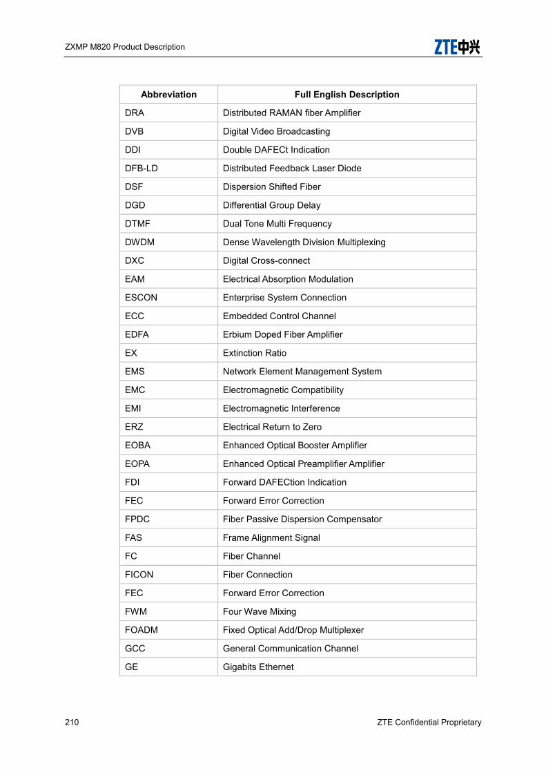
ZXMP M820 Product Description
210 ZTE Confidential Proprietary
Abbreviation Full English Description
DRA Distributed RAMAN fiber Amplifier
DVB Digital Video Broadcasting
DDI Double DAFECt Indication
DFB-LD Distributed Feedback Laser Diode
DSF Dispersion Shifted Fiber
DGD Differential Group Delay
DTMF Dual Tone Multi Frequency
DWDM Dense Wavelength Division Multiplexing
DXC Digital Cross-connect
EAM Electrical Absorption Modulation
ESCON Enterprise System Connection
ECC Embedded Control Channel
EDFA Erbium Doped Fiber Amplifier
EX Extinction Ratio
EMS Network Element Management System
EMC Electromagnetic Compatibility
EMI Electromagnetic Interference
ERZ Electrical Return to Zero
EOBA Enhanced Optical Booster Amplifier
EOPA Enhanced Optical Preamplifier Amplifier
FDI Forward DAFECtion Indication
FEC Forward Error Correction
FPDC Fiber Passive Dispersion Compensator
FAS Frame Alignment Signal
FC Fiber Channel
FICON Fiber Connection
FEC Forward Error Correction
FWM Four Wave Mixing
FOADM Fixed Optical Add/Drop Multiplexer
GCC General Communication Channel
GE Gigabits Ethernet
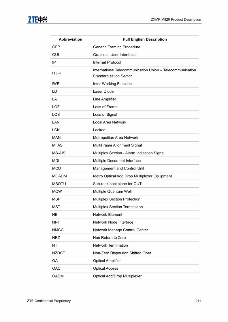
ZXMP M820 Product Description
ZTE Confidential Proprietary 211
Abbreviation Full English Description
GFP Generic Framing Procedure
GUI Graphical User Interfaces
IP Internet Protocol
ITU-T International Telecommunication Union – Telecommunication Standardization Sector
IWF Inter-Working Function
LD Laser Diode
LA Line Amplifier
LOF Loss of Frame
LOS Loss of Signal
LAN Local Area Network
LCK Locked
MAN Metropolitan Area Network
MFAS MultiFrame Alignment Signal
MS-AIS Multiplex Section - Alarm Indication Signal
MDI Multiple Document Interface
MCU Management and Control Unit
MOADM Metro Optical Add Drop Multiplexer Equipment
MBOTU Sub-rack backplane for OUT
MQW Multiple Quantum Well
MSP Multiplex Section Protection
MST Multiplex Section Termination
NE Network Element
NNI Network Node Interface
NMCC Network Manage Control Center
NRZ Non Return to Zero
NT Network Termination
NZDSF Non-Zero Dispersion Shifted Fiber
OA Optical Amplifier
OAC Optical Access
OADM Optical Add/Drop Multiplexer

ZXMP M820 Product Description
212 ZTE Confidential Proprietary
Abbreviation Full English Description
Och Optical Channel
ODF Optical fiber Distribution Frame
ODU Optical Demultiplexer Unit
OGMD Optical Group Mux/DeMux Board
OCI Open Connection Indication
OHP Order wire
OLA Optical Line Amplifier
OLT Optical Line Termination
OMU Optical Multiplexer Unit
OMS Optical Multiplex Section
ONU Optical Network Unit
OPU Optical Protection Unit
OPM Optical Performance Monitor
OPMSN Optical Protect for Mux Section (without preventing resonance switch)
OPMSS Optical Protect for Mux Section (with preventing resonance switch)
OSPF Open Shortest Path First
OSC Optical Supervision Channel
OSNR Optical Signal-Noise Ratio
OTM Optical Terminal Multiplexer
OTN Optical Transport Network
OTU Optical Transponder Unit
OXC Optical Cross-connect
PA Pre-Amplifier
PDL Polarization Dependent Loss
PDC Passive Dispersion Compensator
PM Path Monitoring
POS Packet Over SDH
PSI Payload Structure Identifier
PT Payload Type
PMD Polarization Mode Dispersion
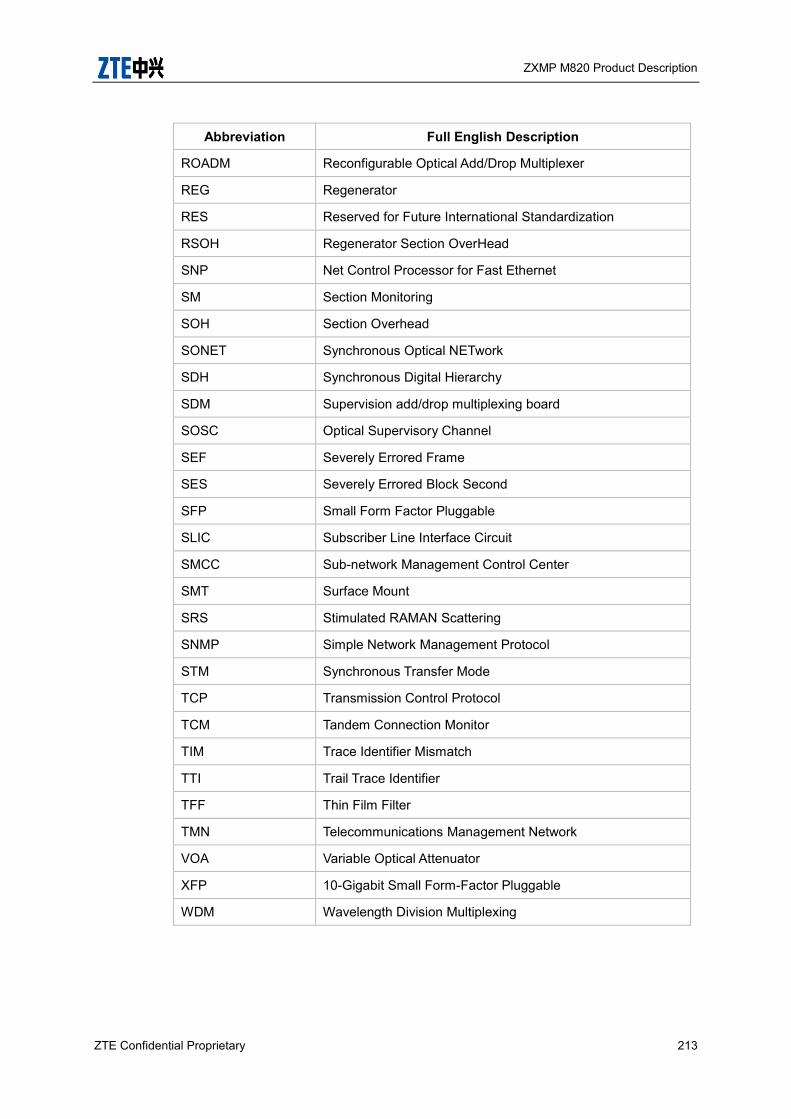
ZXMP M820 Product Description
ZTE Confidential Proprietary 213
Abbreviation Full English Description
ROADM Reconfigurable Optical Add/Drop Multiplexer
REG Regenerator
RES Reserved for Future International Standardization
RSOH Regenerator Section OverHead
SNP Net Control Processor for Fast Ethernet
SM Section Monitoring
SOH Section Overhead
SONET Synchronous Optical NETwork
SDH Synchronous Digital Hierarchy
SDM Supervision add/drop multiplexing board
SOSC Optical Supervisory Channel
SEF Severely Errored Frame
SES Severely Errored Block Second
SFP Small Form Factor Pluggable
SLIC Subscriber Line Interface Circuit
SMCC Sub-network Management Control Center
SMT Surface Mount
SRS Stimulated RAMAN Scattering
SNMP Simple Network Management Protocol
STM Synchronous Transfer Mode
TCP Transmission Control Protocol
TCM Tandem Connection Monitor
TIM Trace Identifier Mismatch
TTI Trail Trace Identifier
TFF Thin Film Filter
TMN Telecommunications Management Network
VOA Variable Optical Attenuator
XFP 10-Gigabit Small Form-Factor Pluggable
WDM Wavelength Division Multiplexing

ZXMP M820 Product Description
214 ZTE Confidential Proprietary
7 Followed Standards and Recommendations The ZXMP M820 is designed with reference to the following recommendations and
standards:
Standard/
Recommendation Title
ITU-T G.652 Characteristics of a single-mode optical fiber and optical cable
ITU-T G.653 Characteristics of Dispersion-Shifted Single-Mode Fiber
ITU-T G.655 Characteristics of Non-Zero Dispersion-Shifted Single-Mode Fibers
ITU-T G.661 Definition and test methods for the relevant generic parameters of optical amplifier devices and subsystems
ITU-T G.662 Generic characteristics of optical fiber amplifier devices and subsystems
ITU-T G.663 Application related aspects of optical amplifier devices and subsystems
ITU-T G.664 Optical safety procedures and requirements for optical transport systems
ITU-T G.665
Definitions and Test Methods for Generic Characteristics Amplifiers
and Raman Amplified Subsystems
ITU-T G.671 Transmission characteristics of passive optical components
ITU-T G.681 Functional characteristics of interoffice and long-haul line systems using optical amplifiers, including optical multiplexing
ITU-T G.691 Optical interfaces for single channel STM-64, STM-256 systems and other SDH systems with optical amplifiers
ITU-T G.692 Optical interface for multichannel systems with optical amplifiers
ITUT-T G.694.1 Spectral grids for WDM application: DWDM frequency grid
ITU-T G.693 Optical interfaces for intra-office systems
ITU-T G.696.1 Optical transport network physical layer interfaces
ITU-T G.697 Optical monitoring for DWDM systems
ITU-T G.709 Interfaces for the Optical Transport Network
ITU-T G.709-2003 Optical Transport Network (OTN) Interfaces
ITU-T G.783 Characteristics of synchronous digital hierarchy (SDH) equipment
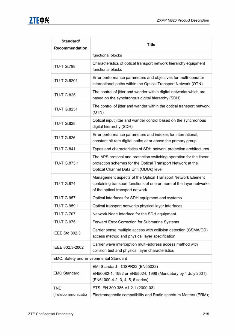
ZXMP M820 Product Description
ZTE Confidential Proprietary 215
Standard/
Recommendation Title
functional blocks
ITU-T G.798 Characteristics of optical transport network hierarchy equipment functional blocks
ITU-T G.8201 Error performance parameters and objectives for multi-operator international paths within the Optical Transport Network (OTN)
ITU-T G.825 The control of jitter and wander within digital networks which are based on the synchronous digital hierarchy (SDH)
ITU-T G.8251 The control of jitter and wander within the optical transport network (OTN)
ITU-T G.828 Optical input jitter and wander control based on the synchronous digital hierarchy (SDH)
ITU-T G.826 Error performance parameters and indexes for international, constant bit rate digital paths at or above the primary group
ITU-T G.841 Types and characteristics of SDH network protection architectures
ITU-T G.873.1 The APS protocol and protection switching operation for the linear protection schemes for the Optical Transport Network at the Optical Channel Data Unit (ODUk) level
ITU-T G.874 Management aspects of the Optical Transport Network Element containing transport functions of one or more of the layer networks of the optical transport network.
ITU-T G.957 Optical interfaces for SDH equipment and systems
ITU-T G.959.1 Optical transport networks physical layer interfaces
ITU-T G.707 Network Node Interface for the SDH equipment
ITU-T G.975 Forward Error Correction for Submarine Systems
IEEE Std 802.3 Carrier sense multiple access with collision detection (CSMA/CD) access method and physical layer specification
IEEE 802.3-2002 Carrier wave interception multi-address access method with collision test and physical layer characteristics
EMC, Safety and Environmental Standard
EMC Standard: EMI Standard---CISPR22 (EN55022)
EN50082-1: 1992 or EN55024: 1998 (Mandatory by 1 July 2001) (EN61000-4-2, 3, 4, 5, 6 series)
TNE (Telecommunicatio
ETSI EN 300 386 V1.2.1 (2000-03)
Electromagnetic compatibility and Radio spectrum Matters (ERM);
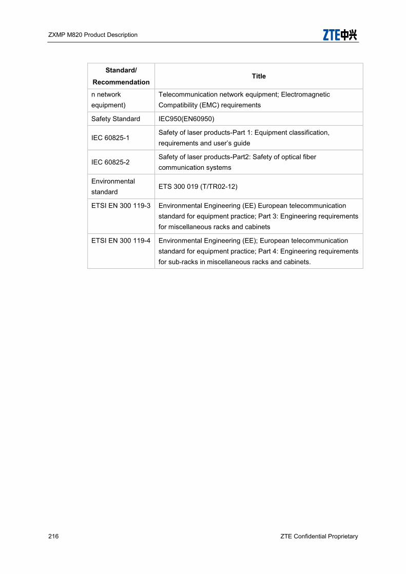
ZXMP M820 Product Description
216 ZTE Confidential Proprietary
Standard/
Recommendation Title
n network equipment)
Telecommunication network equipment; Electromagnetic Compatibility (EMC) requirements
Safety Standard IEC950(EN60950)
IEC 60825-1 Safety of laser products-Part 1: Equipment classification, requirements and user’s guide
IEC 60825-2 Safety of laser products-Part2: Safety of optical fiber communication systems
Environmental standard
ETS 300 019 (T/TR02-12)
ETSI EN 300 119-3 Environmental Engineering (EE) European telecommunication standard for equipment practice; Part 3: Engineering requirements for miscellaneous racks and cabinets
ETSI EN 300 119-4 Environmental Engineering (EE); European telecommunication standard for equipment practice; Part 4: Engineering requirements for sub-racks in miscellaneous racks and cabinets.