مدرسه مهندسی هوافضا و مکانیکdl.samegp.com/digital_liblary/solid works... ·...
TRANSCRIPT

SolidWorks Education EditionGetting Started

© 1995-2002, SolidWorks Corporation 300 Baker AvenueConcord, Massachusetts 01742 USAAll Rights Reserved.
SolidWorks Corporation is a Dassault Systemes S.A. (Nasdaq:DASTY) company.The information and the software discussed in this document are subject to change without notice and should not be considered commitments by SolidWorks Corporation. No material may be reproduced or transmitted in any form or by any means, electronic or mechanical, for any purpose without the express written permission of SolidWorks Corporation.As a condition to your use of this software product, you agree to accept the limited warranty, disclaimer and other terms and conditions set forth in the SolidWorks Corporation Educational License and Subscription Service Agreement, which accompanies the software. If, after reading the License Agreement, you do not agree with the limited warranty, the disclaimer or any of the other terms and conditions, promptly return the unused software and all accompanying documentation to SolidWorks Corporation and your money will be refunded.The software discussed in this document is furnished under a license and may be used or copied only in accordance with the terms of this license. All warranties given by SolidWorks Corporation as to the software and documentation are set forth in the SolidWorks Corporation Educational License and Subscription Service Agreement, and nothing stated in, or implied by, this document or its contents shall be considered or deemed a modification or amendment of such warranties. SolidWorks® is a registered trademark of SolidWorks Corporation.SolidWorks 2001Plus is a product name of SolidWorks Corporation.FeatureManager® is a jointly owned registered trademark of SolidWorks Corporation.Feature Palette™ and PhotoWorks™ are trademarks of SolidWorks Corporation.
ACIS® is a registered trademark of Spatial Corporation.FeatureWorks® is a registered trademark of Geometric Software Solutions Co. Limited.GLOBEtrotter® and FLEXlm® are registered trademarks of Globetrotter Software, Inc.Other brand or product names are trademarks or registered trademarks of their respective holders.
COMMERCIAL COMPUTER SOFTWARE - PROPRIETARYU.S. Government Restricted Rights. Use, duplication or disclosure by the Government is subject to restrictions as set forth in FAR 52.227-19 (Commercial Computer Software - Restricted Rights), DFARS 252.227-7202(Commercial Computer Software and Commercial Computer Software Documentation) and in the license agreement, as applicable. Contractor/Manufacturer: SolidWorks Corporation, 300 Baker Avenue, Concord, Massachusetts 01742 USAPortions of this software are copyrighted by and are the property of Unigraphics Solutions Inc.Portions of this software © 1990-2002 D-Cubed Limited.Portions of this software © 1998-2002 Geometric Software Solutions Co. Limited.Portions of this software © 1999-2002 Immersive Design, Inc.Portions of this software © 1990-2002 LightWork Design Limited.Portions of this software © 1996-2002 Microsoft Corporation. All Rights Reserved.Portions of this software © 1995-2002 Spatial CorporationPortions of this software © 1999-2002 Viewpoint CorporationPortions of this software © 1997-2002 Virtue 3D, Inc.All Rights Reserved.
U.S. Patents 5,815,154, 6,219,049, 6,219,055
Document Number: SWGSEDENG0402
Contents
Mastering the BasicsBasic Functionality 1-1The 40-Minute Running Start 2-1Assembly Basics 3-1Drawing Basics 4-1Design Tables 5-1More about Basic Functionality 6-1
Working with Features and PartsRevolve and Sweep Features 7-1Loft Features 8-1Pattern Features 9-1Fillet Features 10-1More about Features and Parts 11-1
Working with AssembliesAssembly Mates 12-1Advanced Design Techniques 13-1More about Assemblies 14-1
SolidWorks Educational Edition Getting Started iii

Working with Drawings and DetailingAdvanced Drawings and Detailing 15-1Bill of Materials 16-1More about Drawings and Detailing 17-1
Special TopicsSheet Metal Part 18-1Mold Design 19-13D Sketching 20-1Importing Files / Using FeatureWorks Software 21-1Learning to use PhotoWorks 22-1SolidWorks Animator 23-1More about SolidWorks Functionality 24-1
and Additional Products
iv

Mastering the Basics
Basic Functionality
The 40-Minute Running Start
Assembly Basics
Drawing Basics
Design Tables
More about Basic Functionality
SolidWorks Educational Edition Getting Started

1 Basic Functionality
SolidWorks is supported under the Microsoft Windows graphical user interface. SolidWorks Educational Edition Getting Started assumes that you have used Windows before and know basic Windows skills, such as how to run programs, resize windows, and so on.
Before you begin the examples in SolidWorks Educational Edition Getting Started, you should read Chapter 1, to familiarize yourself with some of the fundamentals, including:
� SolidWorks design concepts
� SolidWorks terms
� Getting Help in SolidWorks
NOTE: Before you use SolidWorks, you must register your copy of the software. Visit http://www.solidworks.com/html/company/education.cfm to register your software and to learn about additional products and services that are available to SolidWorks Educational Edition customers.
SolidWorks Educational Edition Getting Started 1-1
Mastering the Basics
Designing with SolidWorks
As you do the examples in this guide, the design methods you use for parts, assemblies, and drawings, represent a unique approach to the design process.
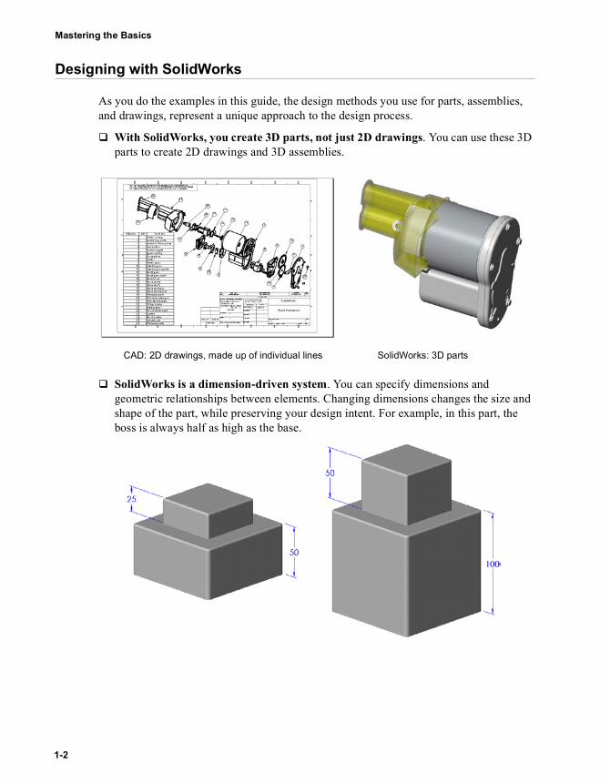
� With SolidWorks, you create 3D parts, not just 2D drawings. You can use these 3D parts to create 2D drawings and 3D assemblies.
� SolidWorks is a dimension-driven system. You can specify dimensions and geometric relationships between elements. Changing dimensions changes the size and shape of the part, while preserving your design intent. For example, in this part, the boss is always half as high as the base.
SolidWorks: 3D partsCAD: 2D drawings, made up of individual lines
1-2

Chapter 1 Basic Functionality
� A SolidWorks 3D model consists of parts, assemblies, and drawings. Parts, assemblies, and drawings display the same model in different documents. Any changes you make to the model in one document are propagated to the other documents containing the model.
� You create sketches and use them to build most features. A sketch is a 2D profile or cross section. Sketches can be extruded, revolved, lofted, or swept along a path to create features.
� You use features to build parts. Features are the shapes (bosses, cuts, holes) and operations (fillets, chamfers, shells, and so on) that you combine to build parts.
Parts Drawings
Assembly
Sketch Sketch extruded 10mm
Base feature
BossCut
Fillet
SolidWorks Educational Edition Getting Started 1-3

Mastering the Basics
SolidWorks Terms
Document Windows
SolidWorks document windows have two panels:
� The left panel of the window contains the following:• The FeatureManager® design tree lists the structure of the part, assembly, or
drawing. For more information, see FeatureManager Design Tree on page 6-9.• The PropertyManager provides an alternate way of sketching and otherwise
interacting with the SolidWorks application. • The ConfigurationManager is a means to create, select, and view multiple
configurations of parts and assemblies in a document.• Customized third-party add-in panels.
� The right panel is the graphics area, where you create and manipulate the part, assembly, or drawing.
ModelGraphicsarea
Left panel displaying the FeatureManager design tree
1-4

Chapter 1 Basic Functionality
Common Model Terms
You should familiarize yourself with the following terms that appear throughout the SolidWorks documentation. For more information about terms, see the glossary in the SolidWorks Online User’s Guide.
Handles
Handles allow you to dynamically drag and set certain parameters without leaving the graphics area. The handle color is set in Tools, Options, System Options, Colors, in the System Color box. Active handles are the Highlight color. Inactive handles are the Inactive Entities color.
In the SolidWorks Educational Edition Getting Started book however, you set all parameters within the PropertyManager in order to familiarize yourself with this method. After you become accustomed to the options in the PropertyManager, you can experiment with handles on your own.
For more information about handles, see the SolidWorks Online User’s Guide.
Axis
FacePlane
Origin Vertex Edge
Handles
SolidWorks Educational Edition Getting Started 1-5

Mastering the Basics
Toolbars
The toolbar buttons are shortcuts for frequently used commands. You can set toolbar placement and visibility based on the document type (part, assembly, or drawing). SolidWorks remembers which toolbars to display and where to display them for each document type. For example, when you open an assembly document, you can choose to display only the Assembly toolbar.
To display or hide individual toolbars:
Click View, Toolbars, or right-click the SolidWorks window frame.
A list of all the toolbars is displayed. The toolbars with a check mark beside them are visible; the toolbars without a check mark are hidden. Click the toolbar name to turn its display on or off.
To customize which toolbars appear for part, assembly, or drawing documents:
1 Open a part, assembly, or drawing document.2 Click Tools, Customize, or right-click over the toolbar area and select Customize.3 On the Toolbars tab, select the check boxes for each toolbar you want to display and
clear the check boxes for the toolbars you want to hide.The toolbars dynamically appear or disappear from the toolbar area.
4 Click OK to accept the changes and close the dialog box; or click Cancel. You can also click Reset to undo the changes and return to the previous settings.
You can move toolbars as desired. Toolbars can be either floating or docked in one of the toolbar areas.
For more information, see Customizing Toolbars on page 6-5.
1-6

Chapter 1 Basic Functionality
Getting Help
If you have questions while you are using the SolidWorks software, you can find answers in several ways:
� For Online help, click or Help, SolidWorks Help Topics in the menu bar. The online help is part of the SolidWorks Online User’s Guide that provides detailed information about using the SolidWorks software.
� For What’s This? help, click on the Standard toolbar, then click a toolbar icon or a FeatureManager item. What’s This? help is also available for certain items in the graphics area.
� For online tutorials that teach you how to create parts, assemblies, and drawings, click Help, Online Tutorial. You will also find information on basic SolidWorks software concepts.
� For ideas about how to best implement your design, click Help, Design Portfolio. The Design Portfolio uses sample parts to provide design ideas.
� For helpful hints, click Help, Tip of the Day. To see a tip each time you start SolidWorks, select the Show tips at startup check box in the Tip of the Day dialog box.
� For help that describes the active dialog box, and provides access to the full online help system, click the Help button in the dialog box or press F1.
� For Tooltips that identify buttons on a toolbar, point at the button, and a moment later, the tooltip pops up.
� As you point at toolbar buttons or click menu items, the Status Bar at the bottom of the SolidWorks window provides a brief description of the function.
For more information and the latest news about the SolidWorks software and company, visit the SolidWorks web site, http://www.solidworks.com, or click Help, About SolidWorks, Connect.
SolidWorks Educational Edition Getting Started 1-7

2 The 40-Minute Running Start
This chapter guides you through the creation of your first SolidWorks model. You create this simple part:
This chapter includes:
� Creating a base feature
� Adding a boss feature
� Adding a cut feature
� Modifying features (adding fillets, changing dimensions)
� Displaying a section view of a part
You should be able to complete this chapter in about 40 minutes.
NOTE: Some of the illustrations in this book have been modified for clarity. What you see on your screen may look different from the illustrations.
SolidWorks Educational Edition Getting Started 2-1
Mastering the Basics
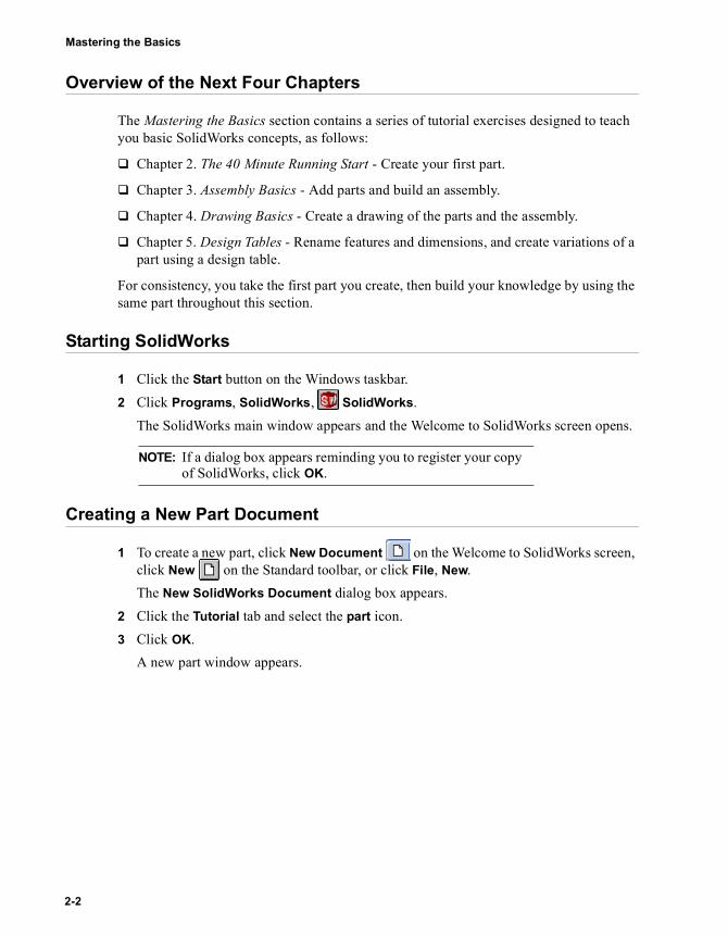
Overview of the Next Four Chapters
The Mastering the Basics section contains a series of tutorial exercises designed to teach you basic SolidWorks concepts, as follows:
� Chapter 2. The 40 Minute Running Start - Create your first part.
� Chapter 3. Assembly Basics - Add parts and build an assembly.
� Chapter 4. Drawing Basics - Create a drawing of the parts and the assembly.
� Chapter 5. Design Tables - Rename features and dimensions, and create variations of a part using a design table.
For consistency, you take the first part you create, then build your knowledge by using the same part throughout this section.
Starting SolidWorks
1 Click the Start button on the Windows taskbar.2 Click Programs, SolidWorks, SolidWorks.
The SolidWorks main window appears and the Welcome to SolidWorks screen opens.
Creating a New Part Document
1 To create a new part, click New Document on the Welcome to SolidWorks screen, click New on the Standard toolbar, or click File, New.The New SolidWorks Document dialog box appears.
2 Click the Tutorial tab and select the part icon. 3 Click OK.
A new part window appears.
NOTE: If a dialog box appears reminding you to register your copy of SolidWorks, click OK.
2-2

Chapter 2 The 40-Minute Running Start
Sketching the Rectangle
The first feature in the part is a box extruded from a sketched rectangular profile. You begin by sketching the rectangle.1 To open a 2D sketch, click Sketch on the Sketch toolbar, or click Insert, Sketch.
A sketch opens on the Front plane.2 Click Rectangle on the Sketch Tools toolbar, or click Tools, Sketch Entity,
Rectangle.3 Move the pointer to the sketch origin. You
know the pointer is on the origin when the pointer changes to . Click the left mouse button and start moving the pointer to create a rectangle. As you move the pointer, notice that it displays the dimensions of the rectangle. Click the mouse button to complete the rectangle.For more information about inferencing pointers and lines, see the SolidWorks Online User’s Guide.
4 Click Select on the Sketch toolbar, or click Tools, Select.The two sides of the rectangle that touch the origin are black. Because you began sketching at the origin, the vertex of these two sides is automatically related to the origin. (The vertex is not free to move.)The other two sides (and three vertices) are blue. This indicates that they are free to move.
5 Click one of the blue sides, and drag the side or the drag handle at the vertex to resize the rectangle.
SolidWorks Educational Edition Getting Started 2-3
Mastering the Basics
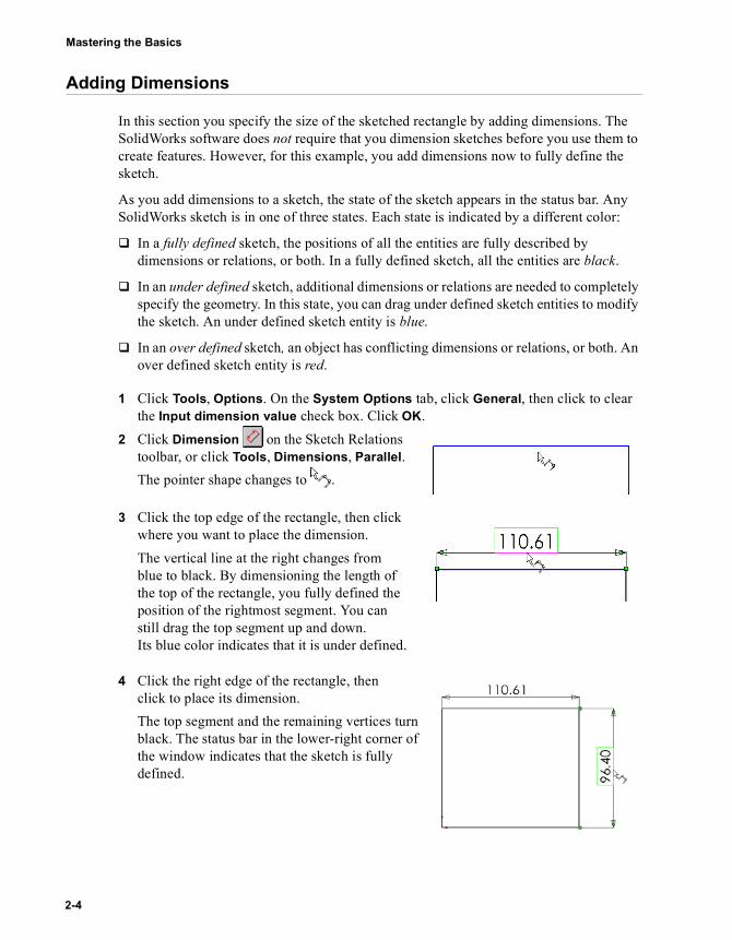
Adding Dimensions
In this section you specify the size of the sketched rectangle by adding dimensions. The SolidWorks software does not require that you dimension sketches before you use them to create features. However, for this example, you add dimensions now to fully define the sketch.
As you add dimensions to a sketch, the state of the sketch appears in the status bar. Any SolidWorks sketch is in one of three states. Each state is indicated by a different color:
� In a fully defined sketch, the positions of all the entities are fully described by dimensions or relations, or both. In a fully defined sketch, all the entities are black.
� In an under defined sketch, additional dimensions or relations are needed to completely specify the geometry. In this state, you can drag under defined sketch entities to modify the sketch. An under defined sketch entity is blue.
� In an over defined sketch, an object has conflicting dimensions or relations, or both. An over defined sketch entity is red.
1 Click Tools, Options. On the System Options tab, click General, then click to clear the Input dimension value check box. Click OK.
2 Click Dimension on the Sketch Relations toolbar, or click Tools, Dimensions, Parallel.The pointer shape changes to .
3 Click the top edge of the rectangle, then click where you want to place the dimension.The vertical line at the right changes from blue to black. By dimensioning the length of the top of the rectangle, you fully defined the position of the rightmost segment. You can still drag the top segment up and down. Its blue color indicates that it is under defined.
4 Click the right edge of the rectangle, then click to place its dimension.The top segment and the remaining vertices turn black. The status bar in the lower-right corner of the window indicates that the sketch is fully defined.
2-4

Chapter 2 The 40-Minute Running Start
Changing the Dimension Values
To change the dimensions, you use the Dimensions tool.1 Double-click one of the dimensions.
The Modify dialog box appears. The current dimension is highlighted.
2 Type 120mm, then click .The sketch changes size to reflect the new dimension. The dimension value is now 120mm.
3 Click Zoom to Fit on the View toolbar, or press the f key, or click View, Modify, Zoom to Fit, to display the entire rectangle at full size and to center it in the graphics area.
4 Double-click the other dimension and change its value to 120mm.5 Click Zoom to Fit again to center the sketch.
SolidWorks Educational Edition Getting Started 2-5

Mastering the Basics
Extruding the Base Feature
The first feature in any part is called the base feature. You create this feature by extruding the sketched rectangle.1 Click Extruded Boss/Base on the Features toolbar, or click Insert, Base,
Extrude.The Base-Extrude PropertyManager appears in the left panel, and the view of the sketch changes to isometric.
2 Under Direction 1, do the following:• Set End Condition to Blind.• Set Depth to 30mm. To increment the
value, either use the arrows or enter the value. When you click the arrows, a preview of the result appears in the graphics area.
3 Click OK to create the extrusion.The new feature, Base-Extrude, appears in the FeatureManager design tree.
4 If you need to zoom to view the entire model, press Z to zoom out, or press Shift+Z to zoom in.
5 Click the plus sign beside Base-Extrude in the FeatureManager design tree. Sketch1, which you used to extrude the feature, is now listed under the feature.
Sketch
Preview ofthe extrusion
Click here
2-6

Chapter 2 The 40-Minute Running Start
Saving the Part
1 Click Save on the Standard toolbar, or click File, Save.The Save As dialog box appears.
2 Type Tutor1 and click Save.
The extension .sldprt is added to the filename, and the file is saved to the current directory. To save the file to a different directory, use the Windows browse button to browse to that directory, then save the file.
NOTE: File names are not case sensitive. That is, files named TUTOR1.sldprt, Tutor1.sldprt, and tutor1.sldprt are all the same part.
SolidWorks Educational Edition Getting Started 2-7

Mastering the Basics
Sketching a Boss
To create additional features on the part (such as bosses or cuts), you sketch on the model faces or planes, then extrude the sketches.
1 Click Hidden Lines Removed on the View toolbar, or click View, Display, Hidden Lines Removed.
2 Click Select on the Sketch toolbar, if it is not already selected.3 Move the pointer over the front face of the part.
The edges of the face become dotted lines to show that the face is available for selection.The pointer changes to to show that you are selecting the face.
4 Click the front face of the part to select it.The edges of the face become solid lines and change color to show that the face is selected.
5 Click Sketch on the Sketch toolbar, or right-click anywhere in the graphics area and select Insert Sketch.A sketch opens.
6 Click Circle on the Sketch Tools toolbar, or click Tools, Sketch Entity, Circle.
7 Click near the center of the face and move the pointer to sketch a circle. Click again to complete the circle.
NOTE: You sketch on one face or plane at a time, then create a feature based on one or more sketches.
2-8

Chapter 2 The 40-Minute Running Start
Dimensioning and Extruding the Boss
To establish the location and size of the circle, add the necessary dimensions.1 Click Dimension on the Sketch Relations toolbar, or right-click anywhere in the
graphics area and select Dimension from the shortcut menu.2 Click the top edge of the face, click the circle, then click a
location for the dimension.Notice the dimension preview as you click each entity. The preview shows you where the witness lines are attached, and that you have selected the correct entities for the dimension. When you add a locating dimension to a circle, the witness line is attached to the center point by default.
3 Click Select, double-click the dimension, then enter 60mm as the new value in the Modify dialog box.
4 Repeat the process to dimension the circle to the side edge of the face. Set this value to 60mm also.
5 Still using the Dimension tool , click the circle to dimension its diameter. Move the pointer around to see the preview for the dimension. When the dimension is aligned horizontally or vertically, it appears as a linear dimension; if it is at an angle, it appears as a diameter dimension.
6 Click a location for the diameter dimension. Set the diameter to 70mm.The circle turns black, and the status bar indicates that the sketch is fully defined.
7 Click Extruded Boss/Base on the Features toolbar, or click Insert, Boss, Extrude.
The Boss-Extrude PropertyManager appears.8 Under Direction 1, set the Depth of the extrusion to
25mm, leave the other items at the defaults, and click OK to extrude the boss feature.Boss-Extrude1 appears in the FeatureManager design tree.
SolidWorks Educational Edition Getting Started 2-9

Mastering the Basics
Creating the Cut
Next, create a cut concentric with the boss.
Sketching and dimensioning the cut1 Click the front face of the circular boss to select it.2 Click Normal To on the Standard Views toolbar.
The part is turned so that the selected model face is now facing you.
3 Click Sketch on the Sketch toolbar to open a new sketch.
4 Sketch a circle near the center of the boss as shown. Click Dimension , and dimension the diameter of the circle to 50mm.
Adding a concentric relation
Now you add a concentric relation between the two circles.1 Click Add Relation on the Sketch Relations toolbar, or click Tools, Relations,
Add.The Properties PropertyManager appears.
2 Select the sketched circle (the inner circle) and the edge of the boss (the outer circle).The selections appear under Selected Entities.
3 Under Add Relations, click Concentric .Concentric appears under Existing Relations. The inner and outer circles now have a concentric relation.
2-10
Chapter 2 The 40-Minute Running Start
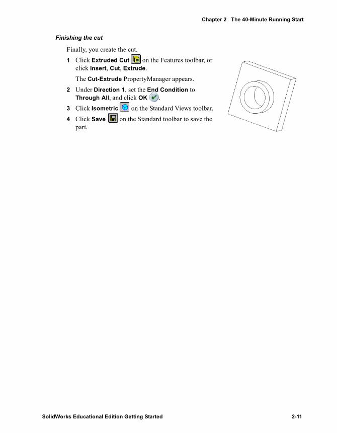
Finishing the cut
Finally, you create the cut.1 Click Extruded Cut on the Features toolbar, or
click Insert, Cut, Extrude.The Cut-Extrude PropertyManager appears.
2 Under Direction 1, set the End Condition to Through All, and click OK .
3 Click Isometric on the Standard Views toolbar.4 Click Save on the Standard toolbar to save the
part.
SolidWorks Educational Edition Getting Started 2-11

Mastering the Basics
Rounding the Corners of the Part
In this section you round the four corner edges of the part. Because the rounds all have the same radius (10mm), you can create them as a single feature.1 Click Hidden In Gray . This makes it easier to
select the hidden edges.2 Click the first corner edge to select it.
Notice how the faces, edges, and vertices highlight as you move the pointer over them, identifying selectable objects. Also, notice the changing pointer shape:
3 Click Rotate View on the View toolbar, or click View, Modify, Rotate, and drag to rotate the part approximately as shown.
4 Click Select , then hold down the Ctrl key and click the four corner edges.
5 Click Fillet on the Features toolbar, or click Insert, Features, Fillet/Round.The Fillet PropertyManager appears with a preview of the fillet.A callout appears that shows the Radius .Under Items to Fillet, the Edge fillet items box shows the four selected edges.
6 Make sure the Radius is set to 10mm. Leave the remaining items at the default values.
7 Click OK .The four selected corners are rounded. The Fillet1 feature appears in the FeatureManager design tree.
Edge
Face
Vertex
Select these four edges
2-12

Chapter 2 The 40-Minute Running Start
Adding More Fillets
Now add fillets and rounds to other sharp edges of the part. You can select faces and edges either before or after opening the Fillet PropertyManager.1 Click Hidden Lines Removed .2 Click Fillet .
The Fillet PropertyManager appears.3 Click the front face of the base to select it.
A preview of the fillet appears on the outside edge of the base-extrude and the boss.The Edges, Faces, Features, and Loops list shows that one face is selected. The callout indicates the Radius .
4 Under Items to Fillet, change the Radius to 5mm, and click OK .The inside edge is filleted and the outside edge is rounded in a single step.
5 Click Fillet again.
6 Click the front face of the circular boss.
7 Change the Radius to 2mm, and click OK .
Notice that the features listed in the FeatureManager design tree appear in the order in which you created them.
8 Click Rotate View and rotate the part to display different views.
9 Click Save to save the part.
SolidWorks Educational Edition Getting Started 2-13

Mastering the Basics
Shelling the Part
Next, you shell the part. Shelling hollows out the part by removing material from the selected face, leaving a thin-walled part.1 Click Back on the Standard Views toolbar.
The back of the part now faces towards you.2 Click Shell on the Features toolbar, or click
Insert, Features, Shell.The Shell1 PropertyManager appears.
3 Click the back face to select it.The selected face appears under Parameters in the Faces to Remove list.
4 Under Parameters, set the Thickness to 2mm and click OK .
The shell operation removes the selected face.5 To see the results, click Rotate View
and rotate the part.
You may need to drag parts to different areas of a window. 1 Click Pan on the View toolbar, or
click View, Modify, Pan, then click the part, drag it to a new location, and release the mouse button.
2 Click Pan again to turn off the Pan tool.
2-14

Chapter 2 The 40-Minute Running Start
Changing a Dimension Using Feature Handles
This section illustrates a way to change the dimension of an extruded feature using feature handles. 1 Click Rotate View on the View toolbar and drag to rotate the part approximately as
shown. Click Rotate View again to turn it off.2 Double-click Base-Extrude in the FeatureManager design tree.
The Base-Extrude feature expands to show the sketch it was based on.The feature dimensions appear in the graphics area.
3 Click Move/size features on the Features toolbar.The feature handles for the extruded feature appear. Feature handles allow you to move, rotate, and resize some types of features.
4 Drag the Resize handle to increase the depth of the extrusion from 30mm to 50mm.Watch the pointer for feedback about the dimension you are changing. When you release the pointer, the part rebuilds using the new dimension.
5 Click Move/size features to turn off the features handle display.
6 Click anywhere outside the part in the graphics area to hide the dimensions.
7 Click Save to save the part.
For more information about feature handles, see the SolidWorks Online User’s Guide.
NOTE: You can also change a dimension using the Modify dialog box method as discussed earlier (see page 2-5).
Rotate
Move
Resize(depth)
SolidWorks Educational Edition Getting Started 2-15

Mastering the Basics
Displaying a Section View
You can display a 3D section view of the model at any time. You use model faces or planes to specify the section cutting planes. In this example, you use the Right plane to cut the model view.1 Click Isometric , then click Shaded view mode.2 Click Right in the FeatureManager design tree.
The Right plane becomes highlighted.3 Click Section View on the View toolbar, or click View, Display, Section View.
The Section View dialog box appears.4 Select the Preview check box.
A section cut arrow appears.
If a message appears about the model not being properly sectioned, click OK.
5 Click the up arrow in the Section Position box to set the Section Position to 60mm. A section cut plane appears. The view dynamically updates as you increment the value, which is the offset distance from the Right plane to the section cut plane.The section cut arrow indicates the area of the model that will be visible, starting from the section cut plane and going in the direction of the arrow.
6 Select the Flip the Side to View check box to flip the direction of the section cut arrow.7 Click OK.
The section view of the part is displayed. Only the display of the part is cut, not the model itself. The section display is maintained if you change the view mode, orientation, or zoom.
8 Click to clear Section View . You return to a complete display of the part.
NOTE: When you select the Preview option, the view updates each time you change a value in the dialog box.
TIP: Switch to Top or Front view to better understand how the Section View tool works.
2-16
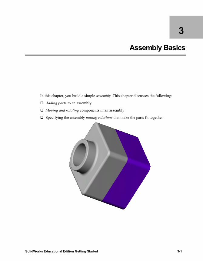
3 Assembly Basics
In this chapter, you build a simple assembly. This chapter discusses the following:
� Adding parts to an assembly
� Moving and rotating components in an assembly
� Specifying the assembly mating relations that make the parts fit together
SolidWorks Educational Edition Getting Started 3-1

Mastering the Basics
Assembly Overview
An assembly is a combination of two or more parts, also called components, within one SolidWorks document. You position and orient components using mates. Mates form relations between faces and edges of components.
In this chapter, you create a new base part and mate it to the part you created in the 40-Minute Running Start chapter, to create an assembly.
For more information about assemblies, see the Working with Assemblies section in this guide.
Creating the Base Feature
You can use the same methods you learned in Chapter 2 to create the base for a new part.1 Open a new part from the Tutorial tab.2 Click Sketch , and sketch a rectangle beginning at the origin.3 Click Dimension , and dimension the rectangle to 120mm x
120mm.4 Click Extruded Boss/Base , and extrude the rectangle, with an
End Condition of Blind, to a Depth of 90mm.
5 Click Fillet , and fillet the four edges shown with a radius of 10mm.
6 Click Shell . Select the front face of the model as the face to remove, and set the Thickness to 4mm.
7 Save the part as Tutor2. (The .sldprt extension is added to the file name.)
3-2

Chapter 3 Assembly Basics
Creating a Lip on the Part
In this section, you use the Convert Entities and Offset Entities tools to create sketch geometry. Then a cut creates a lip to mate with the part from the previous chapter.
1 Click Zoom to Area , or View, Modify, Zoom to Area, and drag-select a corner of the part, as shown. Click Zoom to Area again to turn off the tool.
2 Select the thin wall on the front face of the part, and click Sketch to open a sketch.The edges of the part face are highlighted.
3 Click Convert Entities on the Sketch Tools toolbar, or click Tools, Sketch Tools, Convert Entities.The outer edges of the selected face are projected (copied) onto the sketch plane as lines and arcs.
4 Click the front face again.5 Click Offset Entities on the Sketch Tools toolbar, or
click Tools, Sketch Tools, Offset Entities.6 Set the Offset Distance to 2mm.
The preview shows the offset extending outward.7 Select the Reverse check box to change the offset
direction.8 Click OK .
A set of lines is added in the sketch, offset from the outside edge of the selected face by 2mm. This relation is maintained if the original edges change.
9 Click Extruded Cut , or Insert, Cut, Extrude.10 Under Direction 1, set the Depth to 30mm, and click
OK .
The material between the two lines is cut, creating the lip.
TIP: Use the Selection Filter to make selecting the faces in this section easier. See Chapter 6, “More about Basic Functionality,” for more information.
SolidWorks Educational Edition Getting Started 3-3

Mastering the Basics
Changing the Color of a Part
You can change the color and appearance of a part or its features. 1 Click the Tutor2 icon at the top of the FeatureManager design tree. 2 Click Shaded .3 Click Edit Color on the Standard toolbar.
The Edit Color dialog box appears.4 Click the desired color on the palette, then click OK.5 Save the part.
Creating the Assembly
Now create an assembly using the two parts.1 If Tutor1.sldprt is not open, click Open on the Standard toolbar and open it.2 Click New on the Standard toolbar.
The New SolidWorks Document dialog box appears.3 Select the Tutorial tab, click the assem icon, and click OK.4 Click Window, Tile Horizontally to display all three windows. Close any extra
windows.5 Drag the Tutor1 icon from the top of the FeatureManager design tree for Tutor1.sldprt,
and drop it in the FeatureManager design tree of the assembly window (Assem1). Notice that as you move the pointer into the FeatureManager design tree, the pointer changes to .Adding a part to an assembly this way results in the part automatically inferencing the assembly origin. When a part inferences the assembly origin:• The part’s origin is coincident with the assembly origin.• The planes of the part and the assembly are aligned.
3-4

Chapter 3 Assembly Basics
6 Drag the Tutor2 icon from Tutor2.sldprt, and drop it in the graphics area of the assembly window, beside the Tutor1 part. Notice that as you move the pointer into the graphics area, the pointer changes to .
7 Save the assembly as Tutor. (The .sldasm extension is added to the file name.) If you see a message about saving referenced documents, click Yes.
8 Drag a corner of the assembly window to enlarge it, or click Maximize in the upper-right corner to make the window full size. You no longer need to have the Tutor1.sldprt and Tutor2.sldprt windows in view.
9 Click Zoom to Fit .
SolidWorks Educational Edition Getting Started 3-5

Mastering the Basics
Mating the Components
In this section, you define assembly mating relations between the components, making them align and fit together.1 Click Isometric on the Standard Views toolbar.2 Click Mate on the Assembly toolbar, or click Insert, Mate.3 Click the top edge of Tutor1, then click the
outside edge of the lip on the top of Tutor2.The edges appear in the Entities to Mate list.
4 Under Mate Settings, do the following:• Click Coincident as the mate type.• Click Closest as the Mate Alignment.
5 Click Preview to preview the mate.The selected edges of the two components are made coincident.
6 Click OK .
The position of the Tutor2 component in the assembly is not fully defined, as shown by the (-) prefix in the FeatureManager design tree. Tutor2 still has some degrees of freedom to move in directions that are not yet constrained by mating relations.1 Click Move Component .2 Click the Tutor2 component and hold
down the left mouse button. The pointer changes to .
3 Drag the component from side to side to observe the available degrees of freedom, then release the left mouse button.
4 Click Move Component again to exit move mode.
Select these edges
Tutor1 Tutor2
3-6

Chapter 3 Assembly Basics
Adding More Mates1 Select the rightmost face of one component,
then press Ctrl, and select the corresponding face on the other component.
2 Click Mate .3 Select Coincident and Closest.4 Click Preview to preview the mate.5 Click OK .
6 Repeat steps 1 through 5, selecting the top faces of both components, to add another Coincident mate.
7 Save the assembly.
Select these faces
Select these faces
SolidWorks Educational Edition Getting Started 3-7

4 Drawing Basics
In this chapter, you create a multi-sheet drawing of the parts and assembly from the previous chapters. This chapter includes:
� Opening a drawing template and editing a sheet format
� Inserting standard views of a part model
� Adding model and reference annotations
� Adding another drawing sheet
� Inserting a named view
� Printing the drawing
SolidWorks Educational Edition Getting Started 4-1

Mastering the Basics
Opening a Drawing Template
First you open a drawing template.1 Click New on the Standard toolbar.
The New SolidWorks Document dialog box appears. 2 Select the Tutorial tab, click the draw icon, then click OK.
A new drawing window appears, with note text.
Preparing the Drawing Template FormatNext you prepare the drawing sheet format by changing some text properties.1 Right-click anywhere in the drawing, and
select Edit Sheet Format.2 Click Zoom to Area , zoom in on the title
block at the lower right, then click again to turn off Zoom to Area.
3 Double-click the note with the text <COMPANY NAME>. The pointer changes to when you drag it over <COMPANY NAME>.
4 Change the Note text to the name of your company.5 Click outside of the Note text area to save your changes.6 Click the Note text again.7 Use the Font toolbar to change the font, size, or style.
8 Right-click in the graphics area, and select Edit Sheet to exit the edit sheet format mode.
Next you save the updated drawing sheet format.1 To replace this format as the standard A-Landscape format, click File, Save Sheet
Format.
The Save Sheet Format dialog box appears.2 Click OK.
NOTE: If the Font toolbar is not visible, click View, Toolbars, Font.
4-2

Chapter 4 Drawing Basics
3 Click Yes to confirm that you want to overwrite the existing sheet format. When you choose this format for your own drawings, you will not need to perform these edits again.
Setting the Detailing Options
Next, set the default dimension font, and the style of dimensions, arrows, and other detailing options. For this chapter, use the settings described below. Later, you can set the detailing options to match your company’s standards.1 Click Tools, Options.2 On the Document Properties tab, click Detailing. In the Dimensioning standard
section, in the Trailing zeroes box, select Remove.3 Under Detailing, click Dimensions. Click Font.
The Choose Font dialog box appears.4 In the Height box, click Points, and type or select 16. 5 Click OK.6 Under Detailing, click Arrows, and review the default sizes and styles.
Notice the different attachment styles for edges, faces, and unattached items.7 Click OK to close the dialog box.
For more information about these options, see the SolidWorks Online User’s Guide.
NOTE: To save the sheet format with a new name and to not overwrite the standard sheet format, click File, Save Sheet Format, Custom sheet format. Click Browse and navigate to the directory where you want to save the format. Type a name and click Save. Click OK to close the dialog box.
SolidWorks Educational Edition Getting Started 4-3

Mastering the Basics
Creating a Drawing of a Part
1 Open Tutor1.sldprt if it is not open. Then return to the drawing window.2 Click Standard 3 View on the
Drawing toolbar, or click Insert, Drawing View, Standard 3 View.The pointer changes to .The Standard View PropertyManager displays a message explaining four methods to select a model.
3 From the Window menu, select Tutor1.sldprt. The Tutor1.sldprt window appears.
4 Click in the graphics area of the part window. The drawing window reappears with the three views of the selected part.
Moving Drawing Views
To move a view, click inside its boundary. When the pointer is at the border, it changes to , and you can drag the view in its allowed directions. 1 Click Drawing View2, then drag it up
and down.2 Click Drawing View3, then drag it left
and right.Drawing View2 and Drawing View3 are aligned to Drawing View1, and only move in one direction to preserve the alignment.
3 Click Drawing View1 and drag it in any direction to move all the views at the same time.
4 Move the views on the drawing sheet to the approximate positions shown.
TIP: Another method of creating a Standard 3 View is to tile the windows, and click the part name in the FeatureManager design tree of the part document.
Drawing View2 Drawing View3
Drawing View1
4-4
Chapter 4 Drawing Basics
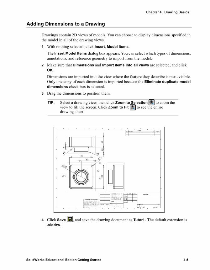
Adding Dimensions to a Drawing
Drawings contain 2D views of models. You can choose to display dimensions specified in the model in all of the drawing views.1 With nothing selected, click Insert, Model Items.
The Insert Model Items dialog box appears. You can select which types of dimensions, annotations, and reference geometry to import from the model.
2 Make sure that Dimensions and Import items into all views are selected, and click OK.Dimensions are imported into the view where the feature they describe is most visible. Only one copy of each dimension is imported because the Eliminate duplicate model dimensions check box is selected.
3 Drag the dimensions to position them.
4 Click Save , and save the drawing document as Tutor1. The default extension is .slddrw.
TIP: Select a drawing view, then click Zoom to Selection to zoom the view to fill the screen. Click Zoom to Fit to see the entire drawing sheet.
SolidWorks Educational Edition Getting Started 4-5

Mastering the Basics
Modifying Dimensions
When you change a model dimension in the drawing view, the model is automatically updated to reflect the change, and vice versa. 1 In Drawing View2, double-click the
dimension for the depth of the boss extrusion.The Modify dialog box appears.
2 Change the value from 25mm to 40mm, and press Enter.
3 Click Rebuild on the Standard toolbar, or click Edit, Rebuild.The part rebuilds using the modified dimension. Both the drawing and the part model are updated.
4 Click Window, and select the Tutor1.sldprt window.
5 Double-click Boss-Extrude1 in the FeatureManager design tree to display the dimensions of the feature.Notice that the depth dimension is 40mm.
6 Return to the drawing window, and save the drawing. The system notifies you that the model referenced in the drawing has been modified, and asks if you want to save it.
7 Click Yes to save both the drawing and the updated model.
Now rebuild the assembly that contains the modified part.1 Open Tutor.sldasm if it is not still open.
If a message appears asking you if you want to rebuild the assembly, click Yes.The assembly rebuilds with the new dimensions.
2 Return to the drawing window.
Double-click this dimension
4-6

Chapter 4 Drawing Basics
Adding Another Drawing Sheet
Now you create an additional drawing sheet for the assembly. You then use the Insert From File command to insert an assembly document into the drawing.1 Click Insert, Sheet.
The Sheet Setup dialog box appears.2 Under both Paper size and Sheet Format, select B-Landscape, and click OK.
Sheet2 opens and is added to the drawing document.3 Click Standard 3 View , right-click in the graphics area, and select Insert From
File. The Insert Component dialog box appears.
4 Set Files of type to Assembly Files (*.asm, *.sldasm), navigate to Tutor.sldasm, and click Open.The Standard 3 Views of the assembly appear on the drawing sheet.
5 Reposition the views on the sheet if needed.
SolidWorks Educational Edition Getting Started 4-7

Mastering the Basics
Inserting a Named View
You can add named views to drawings, showing the model in different orientations. You can use:
• A standard view (Front, Top, Isometric, and so on)• A named view orientation that you defined in the part or assembly• The current view in the part or assembly document
Zoom levels are ignored, however, and the entire model is always displayed in the selected orientation.
In this section you add an isometric view of the assembly.1 Click Named View , or Insert, Drawing View, Named View.
The Named View PropertyManager appears.The pointer indicates that you may select a model to display in the drawing.
2 Select one of the existing drawing views to use.The Named View PropertyManager appears. Note its similarity to the Orientation dialog box.The pointer indicates that you may select a location in the drawing to place the named view.
3 Double-click *Isometric from the list to switch to an isometric view.4 Click where you want to place the view.
4-8

Chapter 4 Drawing Basics
Printing the Drawing
1 Click File, Print. The Print dialog box appears.
2 Set Print range to All.3 Click Setup.
The Print Setup dialog box appears.4 Under Scale, make sure that Scale sheet to fit paper is selected.5 Click OK to close the Print Setup dialog box.6 Click OK again to close the Print dialog box and to print the drawing.7 Click Save .
The system notifies you that the model referenced in the drawing has been modified, and asks if you want to save it.
8 Click Yes, then close the drawing.
SolidWorks Educational Edition Getting Started 4-9

5 Design Tables
In this chapter you use a design table to create several variations of the part you designed in Chapter 2, “The 40-Minute Running Start.” To use a design table, you must have Microsoft Excel on your computer. For more information, see the SolidWorks Read This First.
This exercise demonstrates the following:
� Renaming features and dimensions
� Displaying feature dimensions
� Linking values of model dimensions
� Verifying geometric relations
� Creating a design table
� Displaying part configurations
SolidWorks Educational Edition Getting Started 5-1
Mastering the Basics
Renaming Features
It is a good practice to give meaningful names to the features in your parts, especially when you plan to use a design table. This can save confusion in complex parts, and it is helpful to other people who use the parts later.1 Open Tutor1.sldprt that you created in Chapter 2.2 Change the generic name Base-Extrude to something more meaningful.
a) Click-pause-click on Base-Extrude in the FeatureManager design tree (do not double-click).
b) Type the new name, Box, and press Enter.3 Rename these other features:
• Boss-Extrude1 => Knob• Cut-Extrude1 => Hole_in_knob• Fillet1 => Outside_corners
4 Save the part as Tutor3.sldprt.
Displaying Dimensions
You can display or hide all the dimensions for all the features of the part. Then you can turn the display of dimensions on and off, either individually, or on a feature-by-feature basis.1 Right-click the Annotations folder in the FeatureManager design tree, and select
Show Feature Dimensions. All the dimensions for the part appear. Notice that the dimensions that are part of a feature’s definition (such as the depth of an extruded feature) are blue.
2 Right-click the Fillet2, Fillet3, and Shell1 features in the FeatureManager design tree or in the graphics area, and select Hide All Dimensions.All the dimensions for these features are hidden.
NOTE: Feature names cannot contain the @ character.
TIP: To give descriptive names to features as you create them, click Tools, Options. On the System Options tab, click FeatureManager, then select the Name feature on creation check box. Each time you create a new feature, the name of the new feature in the FeatureManager design tree is automatically highlighted, and ready for you to type a new name.
5-2
Chapter 5 Design Tables
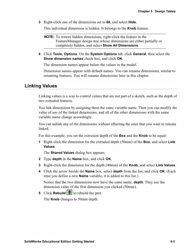
3 Right-click one of the dimensions set to 60, and select Hide.This individual dimension is hidden. It belongs to the Knob feature.
4 Click Tools, Options. On the System Options tab, click General, then select the Show dimension names check box, and click OK.The dimension names appear below the values in the model. Dimension names appear with default names. You can rename dimensions, similar to renaming features. You will rename dimensions later in this chapter.
Linking Values
Linking values is a way to control values that are not part of a sketch, such as the depth of two extruded features.
You link dimensions by assigning them the same variable name. Then you can modify the value of any of the linked dimensions, and all of the other dimensions with the same variable name change accordingly.
You can unlink any of the dimensions without affecting the ones that you want to remain linked.
For this example, you set the extrusion depth of the Box and the Knob to be equal:1 Right-click the dimension for the extruded depth (50mm) of the Box, and select Link
Values. The Shared Values dialog box appears.
2 Type depth in the Name box, and click OK.3 Right-click the dimension for the depth (40mm) of the Knob, and select Link Values. 4 Click the arrow beside the Name box, select depth from the list, and click OK. (Each
time you define a new Name variable, it is added to this list.)Notice that the two dimensions now have the same name, depth. They use the dimension value of the first dimension you clicked (50mm).
5 Click Rebuild to rebuild the part.The Knob changes to 50mm depth.
NOTE: To restore hidden dimensions, right-click the feature in the FeatureManager design tree whose dimensions are either partially or completely hidden, and select Show All Dimensions.
SolidWorks Educational Edition Getting Started 5-3

Mastering the Basics
Renaming Dimensions
You can change individual dimension names. Renaming dimensions is a good practice, and it is especially useful when you plan to use a design table. You use the dimension names to identify the elements you plan to change, and as headings in the design table worksheet.1 Change the name of the knob diameter dimension:
a) Right-click the Knob diameter dimension (70mm), and select Properties.The Dimension Properties dialog box appears.
b) Select the text in the Name box and type in a new name, knob_dia.Notice that the Full name box is updated as you type.
c) Click OK.2 Rename the height of the box (120mm) to box_height.3 Rename the width of the box (120mm) to box_width.4 Rename the diameter of the hole in the knob (50mm) to hole_dia.5 Rename the radius of the outside corners (10mm) to fillet_radius.6 Save the part.
5-4

Chapter 5 Design Tables
Verifying Relations
Before you proceed, you should define some geometric relations that ensure that the knob is positioned correctly with respect to the center of the box, regardless of the size. Relations add to the integrity of the design, and they are often the most effective way to convey the design intent accurately.1 In the FeatureManager design tree or the model, right-click the Knob feature, and
select Edit Sketch.2 Click Hidden Lines Removed , and click Normal To .
The front of the model now faces towards you.3 Delete the dimensions (60mm) between the circle and the sides of the box.4 Click the center point of the circle, and drag the circle to one side.5 Click Centerline , or Tools, Sketch Entity,
Centerline, and sketch a diagonal centerline as shown. Press Esc to exit the Centerline tool.
6 Add a midpoint relation between the centerline and the center point of the circle:a) Click Add Relation , or click Tools,
Relations, Add.The Properties PropertyManager appears.
b) Click the centerline and the center point of the circle.
c) Click Midpoint .The circle turns black, indicating the sketch is now fully defined.
d) Click OK .
Now verify the relations in this sketch:1 Click Display/Delete Relations , or Tools, Relations, Display/Delete.
The Sketch Relations PropertyManager appears.2 Under Edit External References, click each relation.
The entities are highlighted in the graphics area. More information about each relation is shown under Entities.
3 Click OK .4 Click Sketch to close the sketch.5 Save the part.
NOTE: If a sketch entity is selected when you click Display/Delete Relations, only the relations on the selected entity are listed. Click a different entity to display its relations. You can change the criteria in the Edit External References list to specify the types of relations that are displayed.
SolidWorks Educational Edition Getting Started 5-5

Mastering the Basics
Inserting a New Design Table
If you have Microsoft Excel on your computer, you can use it to embed a new design table directly in the part document. A design table allows you to build several different configurations of a part by applying the values in the table to the dimensions of the part.
First you should prepare to insert the design table.1 Click Tools, Options. On the System Options tab, click General.2 Make sure that the Edit design tables in a separate window check box is not
selected, and click OK.3 Click Isometric .4 Press Z to zoom out or Shift+Z to zoom in and resize the part so you can see all of the
part’s dimensions in the graphics area. Use the Pan tool , if necessary, to move the part to the lower right corner of the window.
5 Click Select to deselect any active View tool.
Now you are ready to insert a new design table.
1 Click Insert, Design Table, New.An Excel worksheet appears in the part document window. Excel toolbars replace the SolidWorks toolbars. By default, the third row (cell A3) is named First Instance, and column header cell B2 is active.
2 Double-click the box_width dimension value (120) in the graphics area. Notice that the pointer changes to when it is over a dimension value.The dimension name is inserted in cell B2 and the dimension value is inserted in cell B3. The adjacent column header cell, C2, is activated automatically.
NOTE: If you accidentally click outside the worksheet before entering all the values, click Edit, Design Table, Edit to redisplay the design table.
TIP: To uncover dimensions hidden by the design table, point at the Excel worksheet’s outer dashed border and drag the worksheet to another location in the graphics area. To resize the worksheet, drag the handles at the corners or sides.
5-6
Chapter 5 Design Tables
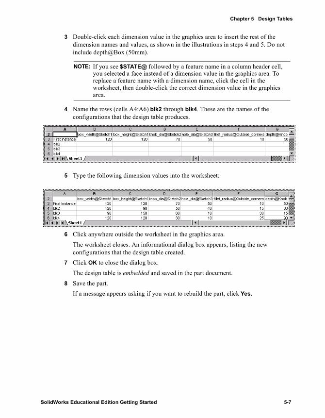
3 Double-click each dimension value in the graphics area to insert the rest of the dimension names and values, as shown in the illustrations in steps 4 and 5. Do not include depth@Box (50mm).
4 Name the rows (cells A4:A6) blk2 through blk4. These are the names of the configurations that the design table produces.
5 Type the following dimension values into the worksheet:
6 Click anywhere outside the worksheet in the graphics area.The worksheet closes. An informational dialog box appears, listing the new configurations that the design table created.
7 Click OK to close the dialog box.The design table is embedded and saved in the part document.
8 Save the part.If a message appears asking if you want to rebuild the part, click Yes.
NOTE: If you see $STATE@ followed by a feature name in a column header cell, you selected a face instead of a dimension value in the graphics area. To replace a feature name with a dimension name, click the cell in the worksheet, then double-click the correct dimension value in the graphics area.
SolidWorks Educational Edition Getting Started 5-7

Mastering the Basics
Viewing the Configurations
Now look at each of the configurations generated by the table.1 Click Shaded .2 Click the ConfigurationManager tab at the bottom of the FeatureManager design
tree.The list of configurations appears.
3 Double-click the name of a configuration.As you display each of the configurations, the part rebuilds using the dimensions for the selected configuration.
5-8

Chapter 5 Design Tables
Editing the Design Table
To make changes to the design table: 1 Click Edit, Design Table, Edit.2 Make the desired changes.3 To close the design table, click anywhere in the graphics area outside the design table.
The configurations update as needed to reflect the changes.
Deleting the Design Table
To delete the design table, click Edit, Design Table, Delete. Deleting a design table does not delete the configurations associated with it.
TIP: When using this or any other OLE object, you may need to click Zoom to Fit when returning to the SolidWorks window.
SolidWorks Educational Edition Getting Started 5-9
6999
More about Basic Functionality
The Mastering the Basics chapters introduce you to many functions available in SolidWorks. The following pages highlight some additional SolidWorks functionality. For more information, see the SolidWorks Online User’s Guide.
This chapter briefly describes SolidWorks functionality in the following areas:
� SolidWorks Fundamentals
� FeatureManager Design Tree
� Opening New and Existing Documents in SolidWorks
� Selection
� Viewing Documents
� Customizing SolidWorks
� Sketching
� Dimensions
� System Options
SolidWorks Educational Edition Getting Started 6-1

Mastering the Basics
SolidWorks Fundamentals
Accessing SolidWorks Documents Using Windows ExplorerWindows Explorer offers you the following functionality:
� Thumbnail images - view thumbnail images of SolidWorks parts and assemblies. The graphic is based on the view orientation of the model when the document was saved.
� Opening documents - open a part, drawing, or assembly document.
� Drag and drop - you can drag and drop:• Any SolidWorks document from Windows Explorer into an empty area of the
SolidWorks window, not occupied by another document window.• A part or assembly from Windows Explorer to an open SolidWorks assembly
window to add an instance of the part or sub-assembly to the assembly.• A part or assembly from Windows Explorer to an open and empty SolidWorks
drawing document to create the standard three views.
Accessing SolidWorks Documents Using Internet ExplorerInternet Explorer version 4.0 or later offers you drag and drop functionality.
You can drag and drop hyperlinks that jump to SolidWorks part files from the Internet Explorer window to:
• The Feature Palette™ window• A new, empty part document• A drawing or assembly document• An empty area of a SolidWorks window
6-2

More about Basic Functionality
Setting Up Different Views of SolidWorks DocumentsThere are several ways you can view SolidWorks documents.
• Multiple Views of Different Documents - you can have multiple part, assembly, and drawing document windows open at the same time.
Part Sub-assembly
Assembly
SolidWorks Educational Edition Getting Started 6-3

Mastering the Basics
• Multiple Views of the Same Document - you can open additional views of the same document. Selecting an item in one view selects it in all views. For example, when creating a fillet you can select edges on the front of the model in one view and edges on the back in another view.
• Split Window View - you can use split controls to split the window into two or four panes. You can zoom, rotate, and set the view mode for each of these views independently.
Vertical Split control
Horizontal Split controlWindow size control
6-4

More about Basic Functionality
Duplicate Panel DisplayYou can display a split instance of the panel adjacent to the graphics area, usually the FeatureManager design tree. A split display is not limited to duplicate FeatureManager design trees. You can select any combination of the following:
• FeatureManager design tree• PropertyManager• ConfigurationManager• Third party applications that use the panel
This option is available either alone or in conjunction with Window, New Window. Without opening a new window, you can display the same part, assembly, or drawing, along with any combination of the panels. With complex designs, for example, you can:
• Display different sections of the part, drawing, or assembly, expanded or collapsed• View different details for configurations• Pick different selections from each panel
PropertyManagerMany functions use the PropertyManager instead of dialog boxes, so your graphics are displayed instead of hidden by dialog boxes. You can use the PropertyManager to set all of the options. You can also apply a color scheme or skins as background images to the PropertyManager.
Customizing ToolbarsYou can customize your toolbar display.
• Moving toolbar buttons - you can move toolbar buttons to different toolbars, change menus, or reset shortcut keys.
• Rearranging toolbars - you can rearrange toolbars in the SolidWorks window. You can dock them at the edge of the window, or make them floating palettes.
SolidWorks Educational Edition Getting Started 6-5

Mastering the Basics
Shortcut MenusWhether you are working with a sketch, a part, an assembly, or a drawing, you have access to a wide variety of tools and commands from the shortcut menu by pressing the right mouse button.
As you move the pointer over geometry in the model or over items in the FeatureManager design tree, right-clicking pops up a shortcut menu of commands that are appropriate for whatever you clicked on.
For example, with the shortcut menu, you can:• Select a sketch tool• Open and close sketches• Change or view the properties of an item• Give a new name to a feature or dimension using the Properties dialog box• Hide or show a sketch, plane, axis, or assembly component• Open an assembly component for editing• Access the dimension tools and annotations menu when in a drawing• Find an item in the FeatureManager design tree
ConfigurationManager Shortcut Menu Options
When you hold down the right mouse button in a blank area inside the ConfigurationManager, you can:
• Open the Add Configuration dialog box• Open the Document Properties tab from the Options dialog box directly
Additional Shortcut Menu Options
You have additional shortcut menu functions, if you prefer using the right mouse button rather than the menu bar. These added functions appear where appropriate. They include:
• Delete - delete a feature or portion of sketch, or a Bill of Materials (BOM) in a drawing
• Suppress/Unsuppress - suppress or unsuppress a feature or a component• Edit Equation - edit an equation when you select the driven dimension in the sketch• Open - open a part file or a top-level assembly over drawings• Mate - mate components in an assembly• Move Component - move a component in an assembly
Accepting FeaturesYou have several streamlined ways to accept features you create. After creating a preview of a feature, you can do the following:
6-6

More about Basic Functionality
• Right-click and select from the shortcut menu• Click icons in the Confirmation Corner of the SolidWorks graphics area
• Right-click to accept the preview when the pointer changes to
What’s Wrong?The SolidWorks application offers a “What’s Wrong” functionality. With this function, you can view information about any errors that occur when rebuilding a part or assembly.
A red circle with a down-pointing arrow next to the part or assembly name at the top of the FeatureManager design tree alerts you that there is a problem. An exclamation mark (!) indicates the item responsible for the error.
Some common errors in rebuilding include:• Dangling dimensions or relations – dimensions or
relations to a non-existent entity• Features that cannot be rebuilt, such as a fillet that
is too large
The Rebuild Errors dialog box displays the rebuild error information.
OK
Cancel
Exit Sketch
Cancel
SolidWorks Educational Edition Getting Started 6-7

Mastering the Basics
Keyboard ShortcutsKeyboard shortcut keys are available for many menu items. Look for the underlined letters in the main menu bar.
Also, look for the underlined letter for each of the menu items. When the menu is pulled down, pressing an underlined letter activates the related command.
Some commands also have shortcut keys that are displayed on the menu beside the command. For example, the combination Ctrl + N opens a new file.
You can customize the keyboard shortcut keys to suit your style of working.
The following table lists some of the frequently used default keyboard shortcuts.
Print BackgroundYou have the option to print the window background, which can consist of viewport colors, gradient colors, or a TIFF image. The Print Background option in the Print dialog box is disabled by default.
Action Key Combination
Rotate the model:• horizontally or vertically Arrow keys• horizontally or vertically 90 degrees Shift + Arrow keys• clockwise/counterclockwise Alt + left or right Arrow keys
Scroll the model Ctrl + Arrow keysOrientation dialog box Spacebar
Zoom in Shift + Z
Zoom out Z
Zoom to fit F
Rebuild the model Ctrl + B
Force rebuild the model and all its features Ctrl + Q
Redraw the screen Ctrl + R
6-8

More about Basic Functionality
FeatureManager Design Tree
The FeatureManager design tree and the graphics display window are dynamically linked. You can select features, sketches, drawing views, and construction geometry in either pane.
The FeatureManager design tree offers you the following functionality:
� Feature order - change the order in which features are rebuilt.
� Feature names - change feature names.
� Moving and copying features - you can move features by dragging them in the model. For example, you can move a hole to a different face. You can also copy or move a fixed-radius fillet or a chamfer using drag-and-drop.
� Dragging and dropping between open documents - you can drag a part or assembly name from the FeatureManager design tree to a drawing document.
� Suppress/Unsuppress - suppress or unsuppress selected features.
� Dimensions - display and control the dimensions of a feature.
� Annotations - filter, scale, and control the display of annotations using the Annotations folder.
� Lighting - adjust the kind and amount of lighting that illuminates a shaded part or assembly using the Lighting folder.
� Rollback bar - temporarily roll the model or assembly back to an earlier state using the rollback bar.
� Equations - add a new equation, edit, or delete an equation using the Equations folder.
FeatureManager design tree
Tabs Graphics area
Rollback bar
SolidWorks Educational Edition Getting Started 6-9

Mastering the Basics
� Tabs - use the tabs at the bottom of the FeatureManager design tree to show you the current FeatureManager function.
� Symbols - view symbols to get information about:• Any parts or features with external references. An external reference is a
dependency on geometry that exists in another document.• The state of sketches (over defined, under defined, not solved).• The state of assemblies and assembly mates.
� Rebuild Icon - the rebuild icon appears when you are required to rebuild a part.
� Flyout FeatureManager design tree - you can click the PropertyManager title or the FeatureManager design tree tab to view the FeatureManager design tree and the PropertyManager at the same time.
A part or a sketch document is open for editing and viewing.An assembly is open for editing, adding components, creating configurations, and viewing.A drawing document is open for viewing or editing.The PropertyManager functionality is in use. The ConfigurationManager tab is in use, where you create, select, and view the configurations of a part or assembly.
Flyout FeatureManager FeatureManager design tree Tab design tree
PropertyManagerTitle
6-10
More about Basic Functionality
Opening New and Existing Documents in SolidWorks
Document TemplatesTemplates are documents (parts, drawings, and assemblies) that include user-defined parameters. Templates allow you to maintain as many different documents for parts, drawings, or assemblies as you need. A template can be a blank document, or it can be a part, drawing, or assembly that you saved as a template. For example, you can create:
• A document template using millimeters and another template using inches• A document template using ANSI and another template using ISO dimensioning
standard• A base part in a document that you use for mold design
When you open a new part, drawing, or assembly, the New SolidWorks Document dialog box appears. The dialog box has tabs for you to organize templates, shows you a preview of templates, and allows you to configure the display of templates for any of the tabs. You can also create additional tabs.
Web FoldersWeb folders is a tool that allows multiple users to share and work on SolidWorks part, assembly, or drawing documents, as well as other file formats, across the Internet. You can save files to a web folder and open files from a web folder.
Selection
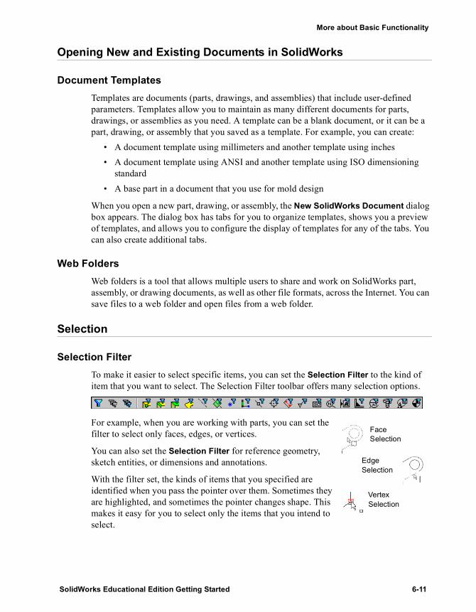
Selection FilterTo make it easier to select specific items, you can set the Selection Filter to the kind of item that you want to select. The Selection Filter toolbar offers many selection options.
For example, when you are working with parts, you can set the filter to select only faces, edges, or vertices.
You can also set the Selection Filter for reference geometry, sketch entities, or dimensions and annotations.
With the filter set, the kinds of items that you specified are identified when you pass the pointer over them. Sometimes they are highlighted, and sometimes the pointer changes shape. This makes it easy for you to select only the items that you intend to select.
Face Selection
Edge Selection
Vertex Selection
SolidWorks Educational Edition Getting Started 6-11

Mastering the Basics
Selection MethodsYou can select entities using the following methods:
• Box Selection - you can select all entity types in parts, assemblies, and drawings by dragging a selection box.
• Loop and Tangent Selection - you can select a group of tangent curves, edges, or faces, or a loop of connecting edges, using the right mouse button.
• Open Loop and Open Tangency Selection - you can propagate a selection along the edges of a surface model where there is a gap to one side of the selected edge, using the right mouse button.
Highlighting SelectionsItems that you select are highlighted using a solid style font. Edges that you select highlight as thick solid lines; edges of faces that you select highlight as thin solid lines.
Viewing Documents
Dynamic and Shaded Previews
These previews help you visualize features you create before accepting them. When you click a feature that supports dynamic previews, and then move the pointer, you see a dynamic preview in the graphics area of how the model changes.
Shaded previews give you a shaded preview of features you create, helping you visualize features before accepting them.
6-12

More about Basic Functionality
Popup tooltipsPop-up tooltips help guide you in building models. The pop-up tooltips appear with an informational message, then disappear after a few seconds. They replace message boxes that require you to click OK to close them.
Middle Mouse Button FunctionsWith a three-button mouse, you can dynamically use the following view commands:
• Pan all document types - hold down Ctrl and click the middle mouse button• Rotate part or assembly - click the middle mouse button• Zoom all document types - hold down Shift and click the middle mouse button
Orientation Dialog Box You can use the Orientation dialog box to:
• Create your own named views• Switch to any of the standard views, or to two additional views,
*Trimetric and *Dimetric
• Change the orientation of all the standard views• Restore all of the standard views to their default settings
NOTE: In an active drawing, to pan you can use the middle mouse button with or without holding down Ctrl.
If you use a three-button mouse, you may need to install the appropriate software or configure the device through Windows Program Manager. Consult the documentation included with your mouse.
Pop-up tooltip
SolidWorks Educational Edition Getting Started 6-13

Mastering the Basics
Customizing SolidWorks
Customizing SolidWorks Functionality Using the Options Dialog BoxThe SolidWorks application lets you customize functionality to suit your needs.
• System Options tab - set options, such as system colors and spin box increments, that are stored in the registry and affect all current and future documents.
• Document Properties tab - set options, such as grid/snap and units, that apply only to the current document. This tab is available only when you have a document open.
Preparing to Print Using Print OptionsUse File, Print to access the Setup, Header/Footer, Line Weights, and Margins buttons. Use Setup to set the following print options:
• Scale• Drawing Color• Paper• Orientation
You can also set the Line Weights and Margins that work best with your printer or plotter. These settings apply for all SolidWorks documents that you print until you change the setup.
You can use Header/Footer to create custom headers and footers for individual documents before printing. Options include:
• Select a predefined header or footer• View your selection in the Preview
boxes• Select Custom Header or Custom
Footer
• Select a Font style and size for custom-created headers and footers
Custom headers or footers can include: • Page Numbers• Number of Pages• Date• Time• Filename
Page Numbers
Date
Number of Pages
Time
Filename
6-14

More about Basic Functionality
SkinsYou can apply skins as background images to the PropertyManager. Skins are bitmap images that appear behind the PropertyManager data. You can also create your own PropertyManager buttons.
SolidWorks contains a selection of skins, or you can use your own bitmap images to create skins.
Sketching
In the Mastering the Basics section, you sketched rectangles and circles. In subsequent chapters, you will sketch lines, arcs, and ellipses. The examples also use geometric relations, 3D sketching, and the sketch tools Fillet, Mirror, Convert Entities, Offset Entities, Extend, and Trim. Additional sketch modes, entities, and tools are described below.
Sketch Modes• You can sketch in either click-drag or click-click mode. If you click the first point
and drag, you are in click-drag mode. If you click the first point and release the pointer, you are in click-click mode. The software recognizes the mode automatically from your first action.
• You can transition between lines and tangent arcs automatically, assisted by tangent arc intent zones (only in click-click mode).
• You can sketch in a grid and snap to grid lines and points.
SolidWorks Educational Edition Getting Started 6-15

Mastering the Basics
Sketch Entities• Parabola - specify the focus and drag to define the extent• Parallelogram - specify one corner, drag two sides• Point - click in the graphics area to specify position• Polygon - specify number of sides, coordinates of center, diameter of inscribed
or circumscribed circle, and angle of rotation• Spline - create a spline by specifying control points and specifying if it is
proportional; modify a spline by specifying geometric relations for the points or by using the shortcut menu tools Moving Frame, Insert Spline Point, Simplify Spline, or Inspect Curvature.
• Text - open a sketch on a model face to add text (parts only)
Sketch Tools• Circular Step Sketch and Repeat - creates a circular array of sketch entities• Construction Geometry - converts sketched entities to construction geometry,
and construction geometry to sketched entities• Face Curves - extracts 3D iso-parametric curves from faces or surfaces• Intersection Curve - creates a sketched curve at the intersection of two
surfaces, a plane and a surface or face, a surface and a face, a plane and a part, or a surface and a part
• Linear Step Sketch and Repeat - creates a linear array of sketch entities• Sketch Chamfer - bevels the intersections of sketched lines• Split Curve - splits a curve to create two sketch entities
Many other sketch tools support creating, editing, and analyzing sketches, including the following:
• Check sketches for errors• Automatically solve the sketch geometry as you create a part• Align the sketch grid with a selected model edge• Automatically create relations as you add sketch entities• Show automatic inferencing lines• Detach a sketch segment from other entities when you drag the segment• Override dimensions when dragging sketch entities• Close an open profile sketch using existing model edges• Display and create lines and arcs with equal lengths or radii
6-16

More about Basic Functionality
Dimensions
The following dimensioning tips may save you some time.
� Using the Modify box as a calculator - you can type values and arithmetic symbols directly into the box to calculate the dimension.
� Editing dimension positions - you can:• Hide a dimension• Move or copy a dimension to another view in a drawing• Center the dimension text between the witness lines• Click circular handles to flip arrows inside or outside witness lines
� Editing circular feature dimensions - you can:• Drag linear and ordinate circle and arc dimensions by their witness line attachment
points• Change a radius dimension to a diameter dimension• Display a diameter dimension as a linear dimension
� Modifying leaders, text, and arrows - you can modify the appearance of leaders, text, and arrows.
� Creating ordinate dimensions - you can create ordinate dimensions in sketches and drawings.
NOTE: You do not have to type the units, such as mm or in.
Display As Radius Display As Diameter Display As Linear
SolidWorks Educational Edition Getting Started 6-17

Working with Features and Parts
Revolve and Sweep Features
Loft Features
Pattern Features
Fillet Features
More about Features and Parts
SolidWorks Educational Edition Getting Started
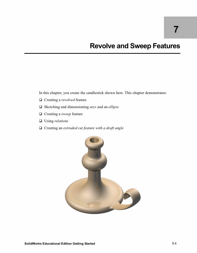
7 Revolve and Sweep Features
In this chapter, you create the candlestick shown here. This chapter demonstrates:
� Creating a revolved feature
� Sketching and dimensioning arcs and an ellipse
� Creating a sweep feature
� Using relations
� Creating an extruded cut feature with a draft angle
SolidWorks Educational Edition Getting Started 7-1

Working with Features and Parts
Sketching a Revolve Profile
You create the base feature of the candlestick by revolving a profile around a centerline.1 Click New , select the Tutorial tab, and double-
click the Part icon to open a new part.2 Click Sketch to open a sketch on the Front
plane.3 Click Line or Tools, Sketch Entity, Line.
Sketch a vertical line through the origin, and sketch the two horizontal lines as shown.
4 Click Dimension or right-click and select Dimension from the shortcut menu. Dimension the lines as shown.
Now sketch and dimension the arcs and lines needed to complete the profile.1 Click 3 Pt Arc or Tools, Sketch Entity, 3 Point
Arc, and point at the endpoint of the top horizontal line. a) Drag an arc downward for a length of approximately 20mm (L=20), and release
the pointer.b) Then drag the highlighted point to adjust the angle of the arc to 180° (A=180°) and
the radius to 10mm (R=10). Notice that the center point of the arc snaps to the vertical inferencing line.
c) Release the pointer.
TIP: Watch the pointer for feedback and for inferencing. As you sketch, inferencing pointers and lines help you align the pointer with existing sketch entities and model geometry. For more information about inferencing, see the SolidWorks Online User’s Guide.
7-2

Chapter 7 Revolve and Sweep Features
2 Click Line or right-click and select Line, then sketch a vertical line starting at the lower endpoint of the arc.Do not dimension the line at this time.
3 Click 3 Pt Arc or right-click and select 3 Point Arc, and sketch an arc with the following measurements: length of 40mm, angle of 180°, and radius of 20mm.Sketch the arc so that the arc endpoints are coincident with the line.
4 Click Trim or Tools, Sketch Tools, Trim, and point at the sketch segment between the endpoints of the arc.The sketch segment is highlighted. Click the highlighted segment to delete it.
5 Right-click and select Dimension from the shortcut menu. Dimension the upper vertical line to 40mm.
6 Click the vertical lines on each side of the arc. In the Properties PropertyManager do the following:a) Under Add Relations, click Equal .b) Click OK .
7 Click Tangent Arc or Tools, Sketch Entity, Tangent Arc, and point at the endpoint of the lower vertical line. Drag the arc until the angle is 90° and the radius is 60mm. Release the pointer.
8 Sketch another tangent arc. Drag the arc until the endpoint is coincident with the endpoint of the bottom horizontal line.
SolidWorks Educational Edition Getting Started 7-3

Working with Features and Parts
9 Dimension the rest of the sketch as shown. When you are done dimensioning, the sketch is fully defined. (All lines and endpoints are black.)
10 Click Centerline or Tools, Sketch Entity, Centerline, and sketch a vertical centerline through the origin. This centerline is the axis around which the profile revolves.
Creating the Revolve Feature
1 Click Revolved Boss/Base on the Features toolbar, or Insert, Base, Revolve.The Base-Revolve PropertyManager appears.
2 Leave the default values of Revolve Type as One-Direction, and Angle at 360°.
3 Click OK .
4 Save the part as Cstick.sldprt.
7-4

Chapter 7 Revolve and Sweep Features
Sketching the Sweep Path
A sweep is a base, boss, or cut created by moving a section along a path. In this example, you create the candlestick handle by using a sweep.
First, you sketch the sweep path. The path can be an open curve, or a closed, non-intersecting curve. Neither the path nor the resulting sweep may self-intersect.1 Click the Front plane in the FeatureManager design tree, then click Sketch to open
a new sketch.2 Click Front on the Standard Views toolbar, and click Hidden Lines
Removed on the View toolbar.3 Click View, Temporary Axes. Notice that the temporary axis of the revolved base
appears.4 Right-click and select Line. Point at the temporary axis.
The pointer changes to indicating that the pointer is exactly on the temporary axis. 5 Sketch a horizontal line as shown, and dimension
the line to 60mm.6 Select Tangent Arc from the shortcut menu, and
sketch an arc. Dimension the arc to a radius of 150mm.
7 Select the endpoints of the tangent arc, and set the vertical dimension to 65mm.
TIP: If the center point of a radial dimension is out of view, right-click the dimension, and select Properties. Select the Foreshortened radius check box, then click OK.
TIP: As you move the pointer, the dimension snaps to the closest orientation. When the preview indicates the dimension type and location you want, right-click to lock the dimension type. Click to place the dimension.
SolidWorks Educational Edition Getting Started 7-5

Working with Features and Parts
8 Select Tangent Arc from the shortcut menu, and sketch another arc as shown. Dimension it to a radius of 20mm.
9 Click the endpoints of the tangent arc you just sketched. In the Properties PropertyManager do the following:a) Under Add Relations, click Horizontal .b) Click OK .The dimensions and relations prevent the sweep path from changing size and shape when moved.
10 Click Display/Delete Relations or Tools, Relations, Display/Delete.The Sketch Relations PropertyManager appears. It lists all the relations in the current sketch, including both relations that are added automatically as you sketch and relations that you add manually. For example, the coincident relation between the sweep path and the revolved base was added automatically. You control the type of relation you want to see with the Criteria option.
11 Make sure that All in this sketch is displayed in the Criteria box.12 Select each relation in the Relations list.
As you select each relation, its entities are highlighted in the graphics area.13 Click OK .
7-6

Chapter 7 Revolve and Sweep Features
Next, dimension the sweep path with respect to the revolved base.1 Dimension the
horizontal line of the sweep path and the bottom edge of the revolved feature to 10mm.The sweep path is fully defined.
2 Close the sketch.
Sketching the Sweep Section
1 Select the Right plane from the FeatureManager design tree, then click Sketch to open a new sketch.
2 Click Normal To on the Standard Views Toolbar.3 Click Ellipse or Tools, Sketch Entity, Ellipse, and sketch an ellipse anywhere.
4 Dimension the ellipse as shown, and click both end points of the ellipse.
5 Under Add Relations, click Horizontal .
This relation ensures that the ellipse is not slanted.6 Click Isometric .
TIP: To sketch an ellipse, drag horizontally from the center point of the ellipse to set the width of the ellipse, release the pointer, then drag vertically to set the height.
SolidWorks Educational Edition Getting Started 7-7

Working with Features and Parts
7 Click the center point of the ellipse and the endpoint of the horizontal line of the sweep path. Under Add Relations, click Coincident , and click OK .
This coincident relation ensures that the center point of the sweep section lies on the plane of the sweep path.
8 Click View, Temporary Axes to hide the temporary axis.9 Click OK and close the sketch.
Creating the Sweep
Now you combine the two sketches to create the sweep.1 Click Sweep on the Features toolbar, or Insert, Boss, Sweep.
The Boss-Sweep PropertyManager appears.2 Under Profile and Path, make sure the ellipse, Sketch3, appears in Profile . If it is
not displayed, click the ellipse in the graphics area.3 Click Path and select the path, Sketch2, in the graphics area.
Note how the colors in Profile and Path match those in the graphics area.4 Under Options, make sure the Orientation/twist control is set to Follow Path.5 Click OK to create the sweep.
The candlestick’s handle is complete.6 Save the part.
7-8
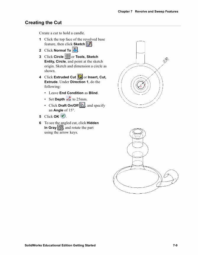
Chapter 7 Revolve and Sweep Features
Creating the Cut
Create a cut to hold a candle.1 Click the top face of the revolved base
feature, then click Sketch .2 Click Normal To .3 Click Circle or Tools, Sketch
Entity, Circle, and point at the sketch origin. Sketch and dimension a circle as shown.
4 Click Extruded Cut or Insert, Cut, Extrude. Under Direction 1, do the following:• Leave End Condition as Blind.• Set Depth to 25mm.• Click Draft On/Off , and specify
an Angle of 15°.5 Click OK . 6 To see the angled cut, click Hidden
In Gray , and rotate the part using the arrow keys.
SolidWorks Educational Edition Getting Started 7-9

Working with Features and Parts
Adding the Fillets
Add fillets to smooth some of the edges on the part.
1 Click Front , and click Hidden Lines Removed .
2 Click Fillet or Insert, Features, Fillet/Round.The Fillet PropertyManager appears.
3 Under Fillet Type, leave the default Constant radius.
4 Under Items to Fillet set Radius to 10mm.
5 Click the four edges indicated.Notice the list of edges in the Edge fillet items box. If you click the wrong edge accidentally, click the edge in the graphics area again to deselect it, or select the name of the edge in the Edge fillet items box and press Delete.
6 Click OK . Fillets are added to each of the selected edges.
7 Click View Orientation , and double-click *Trimetric in the Orientation dialog box.
8 Click Shaded . 9 Save the part.
TIP: Use the Selection Filter to make selecting the edges in this section easier.
Select these four edges
7-10

8 Loft Features
In this chapter, you create this chisel using loft features.
A loft is a base, boss, or cut created by connecting multiple cross sections, or profiles.
This exercise demonstrates the following:
� Creating planes
� Sketching, copying, and pasting the profiles
� Creating a solid by connecting the profiles (lofting)
SolidWorks Educational Edition Getting Started 8-1

Working with Features and Parts
Setting Up the Planes
To create a loft, you begin by sketching the profiles on faces or planes. You can use existing faces and planes, or create new planes. 1 Click New , select the Tutorial tab, and double-click the Part icon to open a new
part.By default, the planes in a SolidWorks model are not visible. However, you can display them. For this example, displaying the Front plane is helpful.
2 Click View, make sure Planes is selected, then right-click the Front plane in the FeatureManager design tree. Select Show from the shortcut menu.
3 With the Front plane still selected, click Plane on the Reference Geometry toolbar, or click Insert, Reference Geometry, Plane.The Plane PropertyManager appears. Under Selections, Front is listed in the Reference Entities box.
4 Set Distance to 25mm and click OK .A new plane, Plane1, is created in front of the Front plane.The planes used in a loft do not have to be parallel, but for this example they are.
5 With Plane1 still selected, click Plane again, and add another offset plane at a distance of 25mm (this is Plane2).
TIP: To make it easier to see the planes as you add them, click View Orientation , and double-click *Trimetric.
8-2

Chapter 8 Loft Features
6 Another way to create an offset plane is to copy an existing plane.Select Plane2 in the graphics area, hold down Ctrl, and drag to a location in front of Plane2.
Another offset plane, Plane3, is created.7 To set the offset distance for the new plane,
double-click Plane3 in the graphics area to display the distance dimension.
8 Double-click the dimension, and change the dimension value to 40mm.
9 Click to save, and click OK to exit the Dimension PropertyManager.
Sketching the Profiles
You create the chisel handle by lofting between simple profile sketches. 1 Click the Front plane either in the FeatureManager design tree or the graphics area,
and click Sketch . Change the view orientation to Front .
2 Sketch and dimension a 60mm square as shown.
3 Exit the sketch.4 Open a sketch on Plane1, and sketch a circle, centered
on the origin. It appears as though you are sketching on top of the first sketch. However, the first sketch is on the Front plane, and it is not affected by sketching on Plane1, a parallel plane in front of it.
5 Dimension the circle to 50mm in diameter. 6 Exit the sketch.
TIP: Drag the edge or the label, not the handles. (Dragging the handles changes the size of the plane display.)
TIP: After adding the dimension, you can center the dimension text between the witness lines. Right-click the dimension, and select Display options, Center between witness lines. If you move the dimension, the text remains centered (unless you drag the text outside the witness lines).
SolidWorks Educational Edition Getting Started 8-3

Working with Features and Parts
7 Open a sketch on Plane2, and sketch a circle, centered on the origin. As you drag, make the diameter of the circle coincident with the vertex of the square. (Watch for the pointer.)
8 Exit the sketch.
Copying a Sketch
You can copy a sketch from one plane to another to create another profile.1 Click Isometric to see how the sketches
line up.
2 Click Sketch3 (the larger circle) in the FeatureManager design tree or in the graphics area.
3 Click Copy on the Standard toolbar, or click Edit, Copy.
4 Click Plane3 in the FeatureManager design tree or the graphics area.
5 Click Paste on the Standard toolbar, or click Edit, Paste.When you paste a sketch on a plane, a new sketch is created automatically on that plane.
6 Save the part as loft.sldprt.
TIP: If a sketch is on the wrong plane, you can change the plane. Right-click the sketch, select Edit Sketch Plane, then click the new plane for the sketch in the FeatureManager design tree.
8-4

Chapter 8 Loft Features
Create the Loft
Now use the Loft command to create a solid feature based on the profiles.1 Click Loft or Insert, Base, Loft.2 Under Options, click to clear the Show preview check box.
This prevents a shaded preview of the loft, but displays how the profiles will be connected.
3 In the graphics area, select each sketch. Click near the same place on each profile (the upper-right side, for example), and select the sketches in the order you want to connect them. A preview shows you how the profiles will be connected. The system connects the points or vertices closest to where you click.
4 Examine the preview of how the profiles will be connected. • If the sketches appear to be connected in
the wrong order, you can use the Move Up or Move Down buttons in the PropertyManager to rearrange the order.
• If the preview indicates that the wrong points will be connected, right-click in the graphics area, select Clear Selections, and select the profiles again.
• To see a preview of the solid base feature, select the Show preview check box.
5 Click OK to create a solid base feature.
Preview shows how profiles will be connected
SolidWorks Educational Edition Getting Started 8-5

Working with Features and Parts
Creating a Boss Loft
For the pointed end of the chisel, you create another loft.1 If the Front plane is not displayed in the graphics area, click the Front plane in the
FeatureManager design tree. Hold down Ctrl, and drag the Front plane to create an offset plane behind the original Front plane.
2 Right-click the new plane, Plane4, and select Edit Definition. In the Plane4 PropertyManager, set the Distance to 200mm.
3 Make sure that Reverse direction is selected, and click OK .4 Change the Orientation to Normal to,
and open a sketch on Plane4. Sketch and dimension a narrow rectangle as shown.
5 Exit the sketch.
6 Change to Isometric view, and clickLoft , or Insert, Boss, Loft.
7 Under Options, click to clear the Show preview check box.
8 Right-click the side of the loft, and click Select Other to pick the square, as shown. Then click the lower part of the narrow rectangular sketch. Examine the preview of how the two profiles will be connected.
9 Click OK and save the part.
TIP: To select an edge or face that is behind the near surface (a hidden edge or face), right-click and choose Select Other from the shortcut menu.
The Yes/No pointer appears. When you point and right-click (N), you cycle through the edges or faces under the pointer, highlighting each of them in turn.
When the edge or face that you want is highlighted, click (Y).
8-6

9 Pattern Features
In this chapter, you learn how to create a linear pattern and a circular pattern. A linear pattern is a one- or two-dimensional array of features. A circular pattern is a circular array of features.
The steps include:
� Creating a revolved base feature
� Using mirroring to create a feature
� Creating a linear pattern
� Creating a circular pattern
� Using an equation to drive the circular pattern
SolidWorks Educational Edition Getting Started 9-1

Working with Features and Parts
Creating the Revolved Base Feature
In this example you create a housing for a microphone. Because the housing is cylindrical, you can create the housing as a revolved feature.1 Click New , select the Tutorial tab, and double-click the Part icon to open a new
part.2 Open a sketch on the Front plane.3 Sketch and dimension the profile as shown.4 Click Fillet on the Sketch Tools toolbar.
a) Set Radius to 30mm.b) Leave Keep constrained corners
selected so that the corner dimensions and relations are retained to a virtual intersection point.
c) Select the endpoint of the 50mm vertical line that is coincident with the endpoint of the diagonal line.
d) Click OK .
The corner is filleted away.
9-2
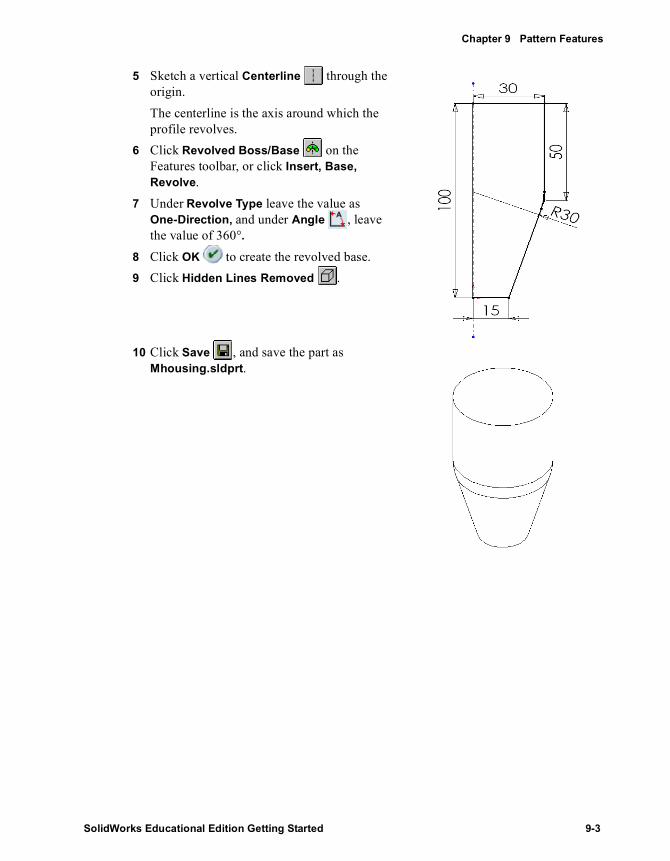
Chapter 9 Pattern Features
5 Sketch a vertical Centerline through the origin. The centerline is the axis around which the profile revolves.
6 Click Revolved Boss/Base on the Features toolbar, or click Insert, Base, Revolve.
7 Under Revolve Type leave the value as One-Direction, and under Angle , leave the value of 360°.
8 Click OK to create the revolved base.9 Click Hidden Lines Removed .
10 Click Save , and save the part as Mhousing.sldprt.
SolidWorks Educational Edition Getting Started 9-3

Working with Features and Parts
Extruding a Thin Feature
Now, create a thin-walled extrusion for the microphone capsule.1 Select the top face and open a sketch.2 Click Top to change the view orientation.3 Click Offset Entities .4 Under Parameters, do the following:
a) Set the Offset Distance to 2mm.b) Select the Reverse check box to offset the edge to
the inside.5 Click OK to exit the Offset Entities
PropertyManager.
6 Click Extruded Boss/Base or Insert, Boss, Extrude.
7 Under Direction 1 do the following:a) Leave End Condition as Blind.b) Specify a Depth of 5mm.
8 Select the Thin Feature check box and do the following:a) Click Reverse Direction to extrude the wall
to the inside.b) Leave Type as One-Direction.c) Set Thickness to 3mm.
9 Click OK to create the thin-walled extrusion.10 Save the part.
9-4

Chapter 9 Pattern Features
Shelling the Part
Hollow out the part by removing the top and bottom faces.1 Click Hidden In Gray .2 Click Shell or Insert, Features, Shell.3 Under Parameters, do the following:
a) Set Thickness to 3mm.b) Click Faces to Remove , then click the top
and bottom faces as shown. Use Select Other from the shortcut menu to select the lower face.
4 Click OK .5 To see the shelled part better, click Shaded and
rotate the part.
Select these faces
SolidWorks Educational Edition Getting Started 9-5

Working with Features and Parts
Creating an Oblong Cut
Next you create a profile of an oblong on a reference plane. Use mirroring to take advantage of symmetry and to decrease the number of relations needed to fully define the sketch.1 Click Hidden Lines Removed .2 Open a sketch on the Front plane, and click Normal To .3 Click Centerline , and sketch a vertical
centerline through the origin.4 Click Line , and sketch two horizontal lines
of equal length, beginning at the centerline.Watch for the on-curve pointer that indicates when you are exactly on the centerline.
5 Click 3 Pt Arc or right-click and select 3 Point Arc. Create a 3-point arc as shown. Adjust the angle of the arc to 180°. Then press Esc to deselect the 3-point arc tool.
9-6

Chapter 9 Pattern Features
6 Mirror the sketch entities.a) Hold down Ctrl, and select the centerline, both horizontal lines, and the 3-point
arc.b) Click Mirror on the Sketch Tools toolbar, or click Tools, Sketch Tools,
Mirror.7 Dimension the oblong as shown.
Now that the sketch is fully defined, create the cut.8 Click Isometric .9 Click Extruded Cut or Insert, Cut, Extrude.
The Cut-Extrude PropertyManager appears.10 Under Direction 1, set End Condition to Through
All.
11 Click OK to create the cut.
SolidWorks Educational Edition Getting Started 9-7

Working with Features and Parts
Creating the Linear Pattern
Next create a linear pattern of the oblong cut. You use a vertical dimension to specify the direction in which to create the linear pattern.1 Double-click Cut-Extrude1 in the FeatureManager design tree.
The dimensions of the Cut-Extrude1 feature appear in the graphics area.2 Click Linear Pattern on the Features toolbar, or click Insert, Pattern/Mirror,
Linear Pattern.3 Under Direction 1, set the following:
a) In the graphics area, click the 60mm dimension as the Pattern Direction.b) If necessary, click Reverse Direction so the arrow in the graphics area points
up.c) Set Spacing to 10mm. This value is the distance from a point on one instance
of the patterned feature to the corresponding point on the next instance.d) Set the Number of instances to 4. This value includes the original cut-extrude
feature.4 Under Features to Pattern , make sure that
Cut-Extrude1 is listed.5 Under Options, select the Geometry pattern check box.
The Geometry pattern option speeds up the creation and rebuilding of the pattern. Individual instances of the feature are copied, but not solved.For more information about Geometry pattern, see the SolidWorks Online User’s Guide.
6 Click OK to create the linear pattern.7 Save the part.
9-8

Chapter 9 Pattern Features
Creating a Circular Pattern of a Linear Pattern
Now create a circular pattern of the linear pattern, using a temporary axis as the axis of revolution.1 Click View, Temporary Axes.2 Click Circular Pattern on the Features
toolbar, or click Insert, Pattern/Mirror, Circular Pattern.The Circular Pattern PropertyManager appears.
3 Under Parameters, set the following:a) In the graphics area, click the temporary axis
that passes through the center of the revolved feature.
Axis <1> appears in the Pattern Axis box. If necessary, click Reverse Direction so the arrow in the graphics area points up.
b) Set Angle to 120°.c) Set Number of Instances to 3.d) If necessary, click to clear the Equal Spacing
check box.4 Under Features to Pattern , make sure that
LPattern1 is listed.5 Under Options, select the Geometry pattern check box.6 Click OK to create the circular pattern.
A circular pattern of the linear pattern is created around the part’s axis of revolution.
7 Click View, Temporary Axes to turn off the display of axes, then click Shaded .
NOTE: If you need to use a circular pattern in a part that does not have a temporary axis in the desired place, you can create an axis, or you can use a linear edge as an axis. For more information about creating an axis, see “Reference Geometry,” in the SolidWorks Online User’s Guide.
SolidWorks Educational Edition Getting Started 9-9

Working with Features and Parts
Using an Equation in the Pattern
You can use an equation to drive the circular pattern. In this example, the equation calculates the spacing angle by dividing 360° by the number of instances desired. This creates a full circle of equally spaced patterns.1 In the FeatureManager design tree, double-click CirPattern1.
Two values appear on the part: 3 (total instances) and 120° (spacing angle).2 Click Equations on the Tools toolbar, or click Tools, Equations.3 Click Add in the Equations dialog box.4 Click the spacing angle value (120) on the part. (You may have to move the dialog
boxes to uncover the dimension.)The name of the value, D2@CirPattern1 (the second dimension in the circular pattern), is entered the New Equation dialog box.
5 Using the calculator buttons in the New Equation box, enter = 360 / (or type =360/).6 Click the total instances value (3). D1@CirPattern1 is added to the equation.
The equation should look as follows:“D2@CirPattern1” = 360 / “D1@CirPattern1”
7 Click OK to complete the equation, and click OK again to close the Equations dialog box. An Equations folder is added to the FeatureManager design tree. To add, delete, or edit an equation, right-click the folder, and select the desired operation.
Now test the equation.1 Increase the total instances of the circular pattern from three to four.
a) Double-click the total instances value (3).b) Set the value in the Modify dialog box to 4.
2 Click in the Modify dialog box to rebuild the model, then click to save the current value and to close the Modify dialog box.– or –Press Enter, then click Rebuild on the Standard toolbar, or click Edit, Rebuild.
3 Save the part.
9-10

10 Fillet Features
This chapter describes how to use different types of fillets. In this example, you create a knob by:
� Using relations in your sketches
� Adding draft angles to extruded features
� Adding fillets• face blend• constant radius• variable radius
� Using mirroring to assure symmetry
� Using circular patterns with equal spacing
SolidWorks Educational Edition Getting Started 10-1

Working with Features and Parts
Creating the Base
You can capture the symmetry of the knob in the design intent of the part. You build one half of the part, then mirror the model to create the other half. Any changes you make to the original half are reflected in the other half.
When you relate features to the origin and the planes, you need fewer dimensions and construction entities. You can more easily modify the part when you build it this way.1 Click New , select the Tutorial tab, and double-click the Part icon to open a new
part. 2 Open a sketch on the Front plane.3 Sketch a centerpoint arc.
a) Click Centerpoint Arc on the Sketch Tools toolbar, or click Tools, Sketch Entity, Centerpoint Arc.
b) Drag downward from the origin. A circumference guideline appears.c) Drag an arc 180° counterclockwise around the origin.
4 Connect the arc endpoints with a vertical line.5 Dimension the arc radius to 15mm.6 Select the line, hold down Ctrl, and click the origin.7 In the Properties PropertyManager, under Add Relations,
click Midpoint and click OK to apply the midpoint relation.
8 Click Extruded Boss/Base or Insert, Base, Extrude.
9 Under Direction 1 do the following:a) Leave End Condition as Blind.b) Set Depth to 10mm.
10 Click OK to create the extrude.
TIP: The pointer changes to when a 180° arc exists.
10-2

Chapter 10 Fillet Features
Creating the Grip
Now, create the grip of the knob.1 Change the view orientation to Right .2 Click the Right plane, and open a sketch.3 Sketch four lines as shown to create the profile.
Do not create any inferenced perpendicular relations between lines.
4 Add a Collinear relation between the vertical sketch line and the model edge.
5 Dimension as shown.6 Click Extruded Boss/Base or Insert, Boss,
Extrude.7 Under Direction 1 do the following:
a) Leave End Condition as Blind.b) Set Depth to 5mm.
8 Click OK to create the extrude.
Adding Draft to the Grip
1 Change the view orientation to *Dimetric.
2 Click Draft on the Features toolbar, or click Insert, Features, Draft.• Leave Type of Draft as Neutral Plane.
• Set Draft Angle to 10°.• Select the Right plane as Neutral Plane.
• Click Faces to Draft, and select the three faces shown.
3 Click OK to create the drafts.
TIP: Use the flyout FeatureManager design tree to select the plane.
Profile
Collinear
Select these faces
SolidWorks Educational Edition Getting Started 10-3

Working with Features and Parts
Creating a Face Blend Fillet
Next, blend some of the faces using a face blend fillet with a hold line. This type of fillet removes the faces that share an edge with the hold line. The distance between the hold line and the selected edges determines the radius of the fillet.1 Click Fillet or Insert, Features, Fillet/Round.2 Under Fillet Type select Face fillet.3 Under Items to Fillet, do the following:
a) Click Face Set 1, and select the face labeled Face set 1.
b) Click Face Set 2, and select the face labeled Face set 2.
4 Under Fillet Options, click Hold line, and select the edge labeled Hold line.
5 Click OK .
6 Save the part as Knob.sldprt.
Face Set 2
Face Set 1
Hold line
10-4

Chapter 10 Fillet Features
Creating Constant Radius Fillets
Now, round some of the edges using a series of constant radius fillets.1 Click Fillet or Insert, Features,
Fillet/Round.a) Under Fillet Type leave as Constant
radius.b) Select the edge of the grip labeled 5mm.c) Under Items to Fillet, set Radius to
5mm.d) Click OK .
2 Repeat step 1 to add fillets to the edges labeled 2mm and 0.5mm. Change the radius values to match the values of the labels.
TIP: When filleted edges intersect, it is good practice to add the larger fillet first.
5mm
2mm
0.5mm
SolidWorks Educational Edition Getting Started 10-5

Working with Features and Parts
Creating a Variable Radius Fillet
1 Click Fillet or Insert, Features, Fillet/Round.
2 Under Fillet Type select Variable radius.3 For Items To Fillet, select the four edges shown
here.
4 Under Variable Radius Parameters, set the radius values for the five vertices as shown in the illustration.a) Click V1 in the Attached Radii box. b) Change the value in the Radius box to
match the value of the label.c) Click each vertex in the Attached Radii
box, and change the value to match the label.The values for each of the vertices appear in the list.
5 Click OK to close the Fillet PropertyManager.
6 Save the part.
TIP: To verify the radius values, double-click VarFillet1 in the FeatureManager design tree.
Select these edges
R1
R1.5
R1.5
R1.5
R1
10-6

Chapter 10 Fillet Features
Mirror the Model
To take advantage of the part’s symmetry and to finish the part, mirror the part about the planar face that is coincident with the Right plane.1 Change the view orientation to Left .2 Click Insert, Pattern/Mirror, Mirror All.3 Select the planar face shown.4 Click OK .
A mirror image of the original part is joined to the part at the selected face to make a complete, symmetrical part.
Fillet the Parting Line
When you mirrored the drafted grip, it created a parting line along the top of the grip. Smooth the parting line by adding a constant radius fillet.1 Change the view orientation to *Dimetric.
2 Click Fillet or Insert, Features, Fillet/Round.a) Select the edge shown.b) Under Fillet Type leave as Constant
radius.c) Under Items To Fillet, set Radius to
5mm.
d) Make sure Tangent propagation is selected.
The fillet extends along all of the segments of the edge.
3 Click OK .
Select this face
Select this edge
SolidWorks Educational Edition Getting Started 10-7
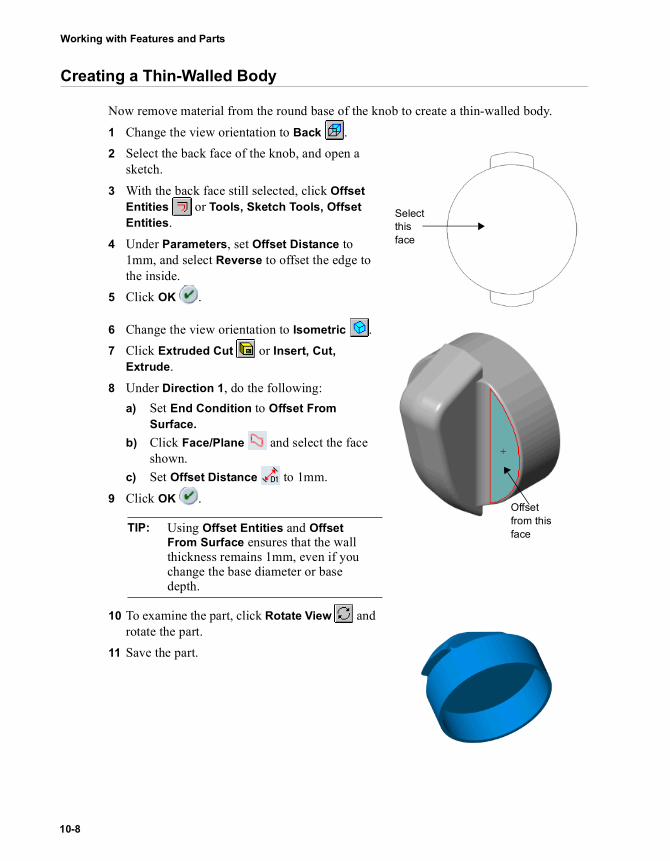
Working with Features and Parts
Creating a Thin-Walled Body
Now remove material from the round base of the knob to create a thin-walled body.1 Change the view orientation to Back .2 Select the back face of the knob, and open a
sketch.3 With the back face still selected, click Offset
Entities or Tools, Sketch Tools, Offset Entities.
4 Under Parameters, set Offset Distance to 1mm, and select Reverse to offset the edge to the inside.
5 Click OK .
6 Change the view orientation to Isometric .7 Click Extruded Cut or Insert, Cut,
Extrude.8 Under Direction 1, do the following:
a) Set End Condition to Offset From Surface.
b) Click Face/Plane and select the face shown.
c) Set Offset Distance to 1mm.9 Click OK .
10 To examine the part, click Rotate View and rotate the part.
11 Save the part.
TIP: Using Offset Entities and Offset From Surface ensures that the wall thickness remains 1mm, even if you change the base diameter or base depth.
Select this face
Offset from this face
10-8
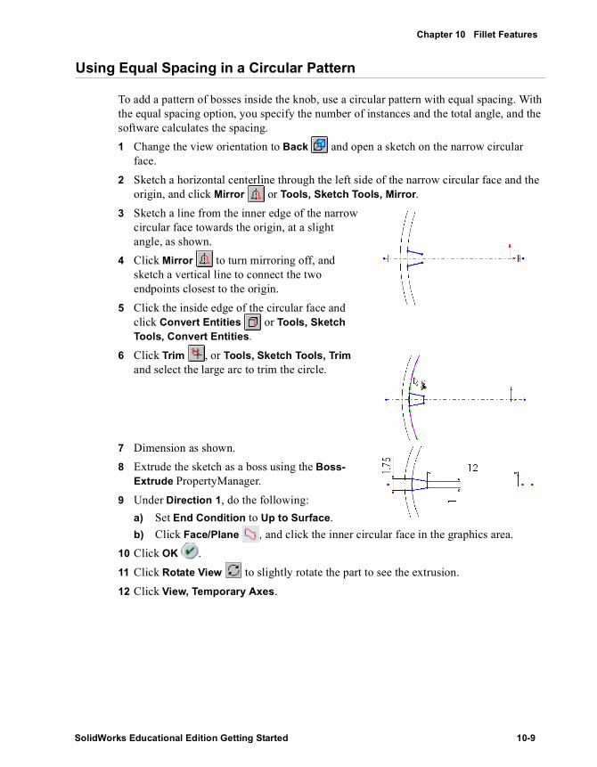
Chapter 10 Fillet Features
Using Equal Spacing in a Circular Pattern
To add a pattern of bosses inside the knob, use a circular pattern with equal spacing. With the equal spacing option, you specify the number of instances and the total angle, and the software calculates the spacing.1 Change the view orientation to Back and open a sketch on the narrow circular
face.2 Sketch a horizontal centerline through the left side of the narrow circular face and the
origin, and click Mirror or Tools, Sketch Tools, Mirror.3 Sketch a line from the inner edge of the narrow
circular face towards the origin, at a slight angle, as shown.
4 Click Mirror to turn mirroring off, and sketch a vertical line to connect the two endpoints closest to the origin.
5 Click the inside edge of the circular face and click Convert Entities or Tools, Sketch Tools, Convert Entities.
6 Click Trim , or Tools, Sketch Tools, Trim and select the large arc to trim the circle.
7 Dimension as shown.8 Extrude the sketch as a boss using the Boss-
Extrude PropertyManager.9 Under Direction 1, do the following:
a) Set End Condition to Up to Surface.b) Click Face/Plane , and click the inner circular face in the graphics area.
10 Click OK .11 Click Rotate View to slightly rotate the part to see the extrusion.12 Click View, Temporary Axes.
SolidWorks Educational Edition Getting Started 10-9

Working with Features and Parts
13 Make sure the boss is selected and click Circular Pattern , or Insert, Pattern/Mirror, Circular Pattern.
14 Under Parameters, do the following:a) Click the Pattern Axis box, then click the
axis through the origin in the graphics area.b) If necessary, click the Equal spacing check
box.The Total Angle changes to 360°.
c) Set Number of Instances to 7.Under Features to Pattern , make sure Boss-Extrude2 is displayed.Under Options, click to clear Geometry pattern, if necessary.
15 Click OK and save the part.
For more information about Geometry pattern, see the SolidWorks Online User’s Guide.
10-10

11
More about Features and Parts
The section “Working with Features and Parts” introduces you to many functions available with SolidWorks. The following pages highlight some additional SolidWorks functionality. For more information, see the SolidWorks Online User’s Guide.
This chapter briefly describes SolidWorks functionality in the following areas:
� Derived parts
� Check entity
� Mass properties
� Section views
� Lighting
� Reference geometry
� Lofts
� Sweeps
� Chamfers
� Ribs
� Patterns
� Scaling
� Hole Wizard
� Surfaces
SolidWorks Educational Edition Getting Started 11-1

Working with Features and Parts
Parts
Parts are the basic building blocks of the SolidWorks mechanical design software. This section highlights some ways to work with parts.
Derived Parts You can select which configuration of the original part to use for a derived part. The three types of derived parts are: Base Part, Mirror Part, and Derived Component Part.
Check Entity The check entity function allows you to verify the integrity of a part.
• Check All - choose to check the entire body, only the solid model, or only the surface bodies
• Check Selected items - select to check more than one entity (face, edge, or surface body) at the same time
• Maximum edge gap and Maximum vertex gap - report the maximum tolerance between the edges and vertices in the selected items.
The Found column displays the number of items found with the specified error, and the Result list box displays the items that are either invalid or too short.
Mass PropertiesDisplays the density, mass, volume, surface area, center of mass, inertia tensor, and principal axes of inertia of a part or assembly model. Capabilities include:
• Density - change the density of a part from the Measurement Options dialog box.• Units - enter the value using any units, and the software converts the value to the
document’s units.• Updates - update the mass properties information when you save a document.• Coordinate Systems - calculate mass properties using a coordinate system. The
moments of inertia are calculated at the origin of the coordinate system, using its axes.
You can add dimensions and mass property parameters into values of custom properties. Changes to the dimensions in the part are associative, so values in the Bill of Materials (BOM) are updated.
You can also insert system-defined, configuration-specific mass properties as custom properties.
11-2

More about Features and Parts
Lighting With Lighting (in the FeatureManager design tree), you can adjust the direction, intensity, and color of the light in the shaded view of the model. As you change the properties of light, a graphical representation of the light source is displayed and the model is updated. The available light properties depend on the type of light source. Light sources include:
� Ambient
� Directional
� Point
� Spot
The sample below displays how you can manipulate Intensity properties for a Directional light source. Brightness controls the amount of light. Specularity controls the extent to which shiny surfaces exhibit bright highlights where the light strikes them.
Reference Geometry
Reference geometry defines the shape or form of a surface or solid. Reference geometry includes planes, axes, coordinate systems, and 3D curves.
Planes You can create any of the following types of planes to facilitate your design intent:
• Offset - a plane parallel to a plane or face, offset by a specified distance• At Angle - a plane through an edge, axis, or sketch geometry at an angle to a face or
a plane• Three Point Plane - a plane through three points (vertices, points, or midpoints)• Parallel Plane at Point - a plane through a point parallel to a plane or face• Line and Point - a plane through a line, axis, or sketch line and a point• Perpendicular to Curve at Point - a plane through a point and perpendicular to an
edge, axis, or sketch curve• On Surface - a plane on a non-planar surface
Higher values for Ambient and Brightness
Higher value for Specularity
SolidWorks Educational Edition Getting Started 11-3
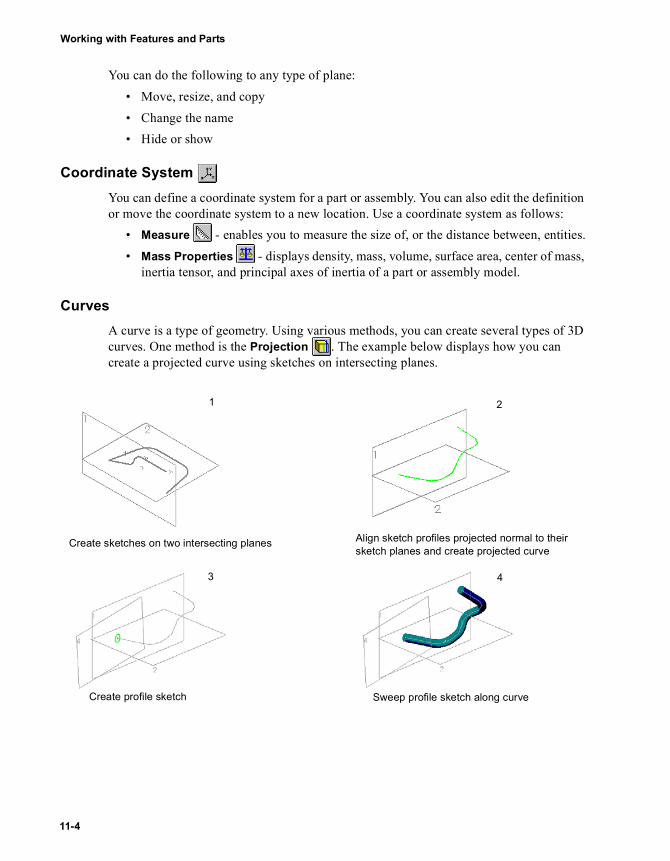
Working with Features and Parts
You can do the following to any type of plane:• Move, resize, and copy• Change the name• Hide or show
Coordinate System You can define a coordinate system for a part or assembly. You can also edit the definition or move the coordinate system to a new location. Use a coordinate system as follows:
• Measure - enables you to measure the size of, or the distance between, entities.• Mass Properties - displays density, mass, volume, surface area, center of mass,
inertia tensor, and principal axes of inertia of a part or assembly model.
CurvesA curve is a type of geometry. Using various methods, you can create several types of 3D curves. One method is the Projection . The example below displays how you can create a projected curve using sketches on intersecting planes.
1 2
3 4
Create sketches on two intersecting planes Align sketch profiles projected normal to their sketch planes and create projected curve
Create profile sketch Sweep profile sketch along curve
11-4

More about Features and Parts
You can also create 3D curves by using the following methods:• Split Line - projecting sketched curves onto selected model faces• Composite Curve - combining curves, sketch geometry, and model edges into a
single curve• Curves Through Free Points - creating 3D splines through points on one or
more planes• 3D Curve - using a point list to create a 3D curve• Helix - specifying values such as pitch and revolutions for a helix or spiral
Features
Features are the individual shapes that, when combined, make up the part. This section describes several SolidWorks features.
� Using additional functionality to some familiar features (such as Loft or Chamfer)
� Creating patterns that are table driven, sketch driven, and irregular by skipping pattern instances
� Applying more complex fillets including, multiple radius fillets, round corner fillets, and setback fillets
� Using uniform and non-uniform scaling to edit models
� Creating complex holes using the Hole Wizard
Loft You can create lofts using various options. For example, you can create a loft using:
• Planar or non-planar profiles
• Parallel or-non parallel planes for the profiles• Guide curves to connect and control intermediate profiles• Center line to act as a guide curve, with all profile planes normal to the center line
Non-planar profile Planar profile
SolidWorks Educational Edition Getting Started 11-5

Working with Features and Parts
• Tangency options to control the tangency at the starting and ending profiles, as well as the magnitude of the tangency.
• Thin features.
Sweeps Among the multiple sweep capabilities, you can create sweeps using thin features and multiple contours.
Controlling the magnitude of the tangency in a loft
Loft with solid feature
Loft with thin feature
Multi-section closed contour with separate curves
Multi-section closed contour with nested curves
11-6

More about Features and Parts
Chamfer Chamfer creates a beveled edge on the selected edges, faces, or both. You can select from several chamfer types (as shown below), and specify the necessary parameters.
Rib Rib is a special type of extruded feature created from an open sketched contour. It adds material of a specified thickness in a specified direction between the contour and an existing part.You can create a rib using either closed or open sketch elements.
Angle-Distance Distance-Distance Vertex-Chamfer
Closed contour
Open contour
SolidWorks Educational Edition Getting Started 11-7
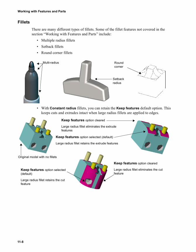
Working with Features and Parts
FilletsThere are many different types of fillets. Some of the fillet features not covered in the section “Working with Features and Parts” include:
• Multiple radius fillets• Setback fillets• Round corner fillets
• With Constant radius fillets, you can retain the Keep features default option. This keeps cuts and extrudes intact when large radius fillets are applied to edges.
Multi-radius
Setback radius
Round corner
Keep features option selected (default)
Large radius fillet retains the extrude features
Keep features option cleared
Large radius fillet eliminates the extrude features
Keep features option cleared
Large radius fillet eliminates the cut feature
Keep features option selected (default)
Large radius fillet retains the cut feature
Original model with no fillets
11-8

More about Features and Parts
Sketch Driven PatternsUsing sketch points within a sketch, you can specify a feature pattern. You can use sketch driven patterns for holes or other feature instances. Sketch driven patterns use:
• Seed features - representing the geometry you want to replicate.• Reference point - using a reference point such as a vertex or a centroid as an origin.• Reference Sketch - representing a sketch on a face of the original part or assembly,
sketch points designate the pattern propagation.
Initial pattern instance
Sketch points for sketch driven patterns
Completed pattern
SolidWorks Educational Edition Getting Started 11-9
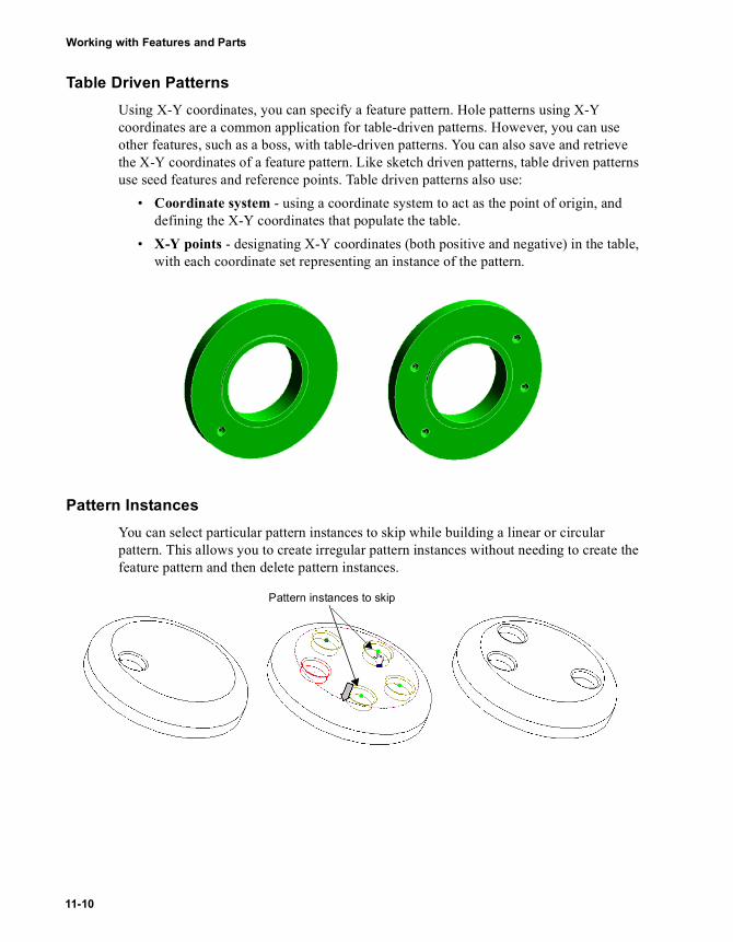
Working with Features and Parts
Table Driven PatternsUsing X-Y coordinates, you can specify a feature pattern. Hole patterns using X-Y coordinates are a common application for table-driven patterns. However, you can use other features, such as a boss, with table-driven patterns. You can also save and retrieve the X-Y coordinates of a feature pattern. Like sketch driven patterns, table driven patterns use seed features and reference points. Table driven patterns also use:
• Coordinate system - using a coordinate system to act as the point of origin, and defining the X-Y coordinates that populate the table.
• X-Y points - designating X-Y coordinates (both positive and negative) in the table, with each coordinate set representing an instance of the pattern.
Pattern InstancesYou can select particular pattern instances to skip while building a linear or circular pattern. This allows you to create irregular pattern instances without needing to create the feature pattern and then delete pattern instances.
Pattern instances to skip
11-10

More about Features and Parts
ScalingYou can select to scale using a coordinate system, the origins or the centroid. You can also select a non-uniform scaling factor by entering X-Y-Z coordinates. For example, you can apply non-uniform scaling by specifying the X-Y-Z coordinates to vary the cavity in a mold.
Hole Wizard The Hole Wizard allows you to create and position different hole types such as counterbore, countersink, and tap.
The hole type you select determines the capabilities, available selections, and graphic previews. After you select a hole type, you determine the appropriate fastener. The fastener dynamically updates the appropriate parameters.
Counterbore preview Counterbore preview up to vertex
Countersink preview Countersink preview offset from surface
Tap hole preview Tap hole preview through all
Normal Part
Results of Uniform Scaling
Results of Non-uniform Scaling
SolidWorks Educational Edition Getting Started 11-11

Working with Features and Parts
In addition to the dynamic graphic preview based on the end condition and depth, graphics in the parameter columns show specific details as they apply to the type of hole you select.
When you create a hole using the Hole Wizard, the type and size of the hole, based on the Description, appears in the FeatureManager design tree.
Creating Holes
With Hole Wizard, you can create holes on planar surfaces and on a plane. By adapting the Hole Wizard to non-planar faces, you can create holes at an angle to the feature.
Favorite Name
For each hole type (except Legacy), you can create, save, update, or delete hole types to include your parameters. This allows you to apply any saved hole types to a SolidWorks document.
Hole Wizard Holes as Assembly Feature
You can add any Hole Wizard hole as an assembly feature that extends through more than one component. Functionality includes display of cosmetic threads on assembly feature holes. Unlike other assembly features, the holes are contained in individual parts as externally referenced features.
11-12

More about Features and Parts
Surfaces
Surfaces are a type of geometry. You can create surfaces, use surfaces to manipulate features, or manipulate the surfaces themselves.
Creating SurfacesYou create surfaces with many of the same tools and principles used to create solids, including:
• Extruded Surface - extrude sketch profile• Lofted Surface - use multiple, parallel or non-parallel planes, with or without
guide curves (see the example below)• Swept Surface - create planes to sketch a sweep profile, sweep path, and guide
curves• Offset Surface - offset surface from a lofted model surface (see the example
below)
• Radiate Surface - create surfaces by radiating a split line, an edge, or a set of contiguous edges inwards or outwards, and parallel to a selected plane (see the example below)
Offset Surface
Guide curve
Guide curve loftRadiate Surface with a Split Line
SolidWorks Educational Edition Getting Started 11-13

Working with Features and Parts
• Revolved Surface - use a surface and revolve about an axis• Mid-Surface - create mid surfaces between selected face pairs as a tool for finite
element modeling• Filled Surface - construct a surface patch within a boundary defined by model
edges. Applications include: parts that imported incorrectly, hole patches in parts for core and cavity molding, and surface construction for industrial design applications.
Manipulate Features with SurfacesYou can use surfaces to create and manipulate features. This includes:
• Fill volumes between surfaces - create a solid body by lofting between two surfaces
• Thicken surface - create model geometry by thickening the surface• Cut part with surface - use surfaces to cut parts (see example below)
Manipulate SurfacesYou can also manipulate surfaces. Some ways of manipulating surfaces include:
• Trimmed Surface - use a surface to trim another surface where they intersect, or use multiple surfaces as mutual trim tools.
Selected surface Direction of cut
Feature section removed Results after the cut
Surface trim
Surface using mutual trim
11-14

More about Features and Parts
• Knit Surface - combine two or more surfaces or faces into one.• Fillet - smooth the edge between adjacent faces in a surface. You can also use
Face Blend to combine multiple surface bodies, or Multiple radius fillet to assign multiple radius values.
• Extended Surface - extend a surface body by selecting one or more edges or faces.
Surfaces before adding the face blend fillet
Surfaces after adding the face blend fillet
Surface extend using Linear
Surface extend using Same Surface
Surface extend using Face
SolidWorks Educational Edition Getting Started 11-15

Working with Features and Parts
• Delete hole - select any closed profile hole on a surface, and click Delete.
Closed profiles Holes deleted
11-16

Working with Assemblies
Assembly Mates
Advanced Design Techniques
More about Assemblies
SolidWorks Educational Edition Getting Started
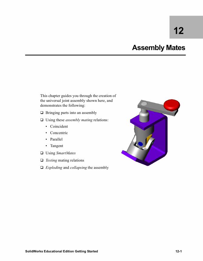
12 Assembly Mates
This chapter guides you through the creation of the universal joint assembly shown here, and demonstrates the following:
� Bringing parts into an assembly
� Using these assembly mating relations:• Coincident• Concentric• Parallel• Tangent
� Using SmartMates
� Testing mating relations
� Exploding and collapsing the assembly
SolidWorks Educational Edition Getting Started 12-1
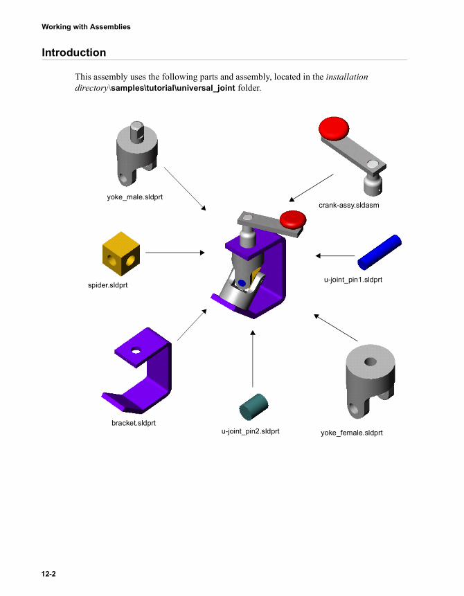
Working with Assemblies
Introduction
This assembly uses the following parts and assembly, located in the installation directory\samples\tutorial\universal_joint folder.
u-joint_pin1.sldprt
u-joint_pin2.sldprt yoke_female.sldprt
crank-assy.sldasmyoke_male.sldprt
spider.sldprt
bracket.sldprt
12-2

Chapter 12 Assembly Mates
Setting the Assembly Load Option
You can load an assembly with its active components fully resolved or lightweight. • Fully resolved. All model information is loaded in memory.• Lightweight. A subset of model information is loaded in memory. The remaining
model information is loaded if the component is selected or if the component is affected by changes that you make in the current editing session.
You can improve the performance of large assemblies significantly by using lightweight components.
The assembly you build in this chapter includes a sub-assembly whose parts could be loaded lightweight. However, there are no significant benefits in using lightweight parts for these reasons:
• The sub-assembly is small, consisting of only three simple components.• You select two of the three components as you build the assembly, thereby resolving
them.1 Before you open the assembly document, click Tools, Options. On the System
Options tab, click Performance.2 Under Assemblies, click to clear the Automatically load parts lightweight check
box, then click OK.
For more information about lightweight parts, see the SolidWorks Online User’s Guide.
SolidWorks Educational Edition Getting Started 12-3
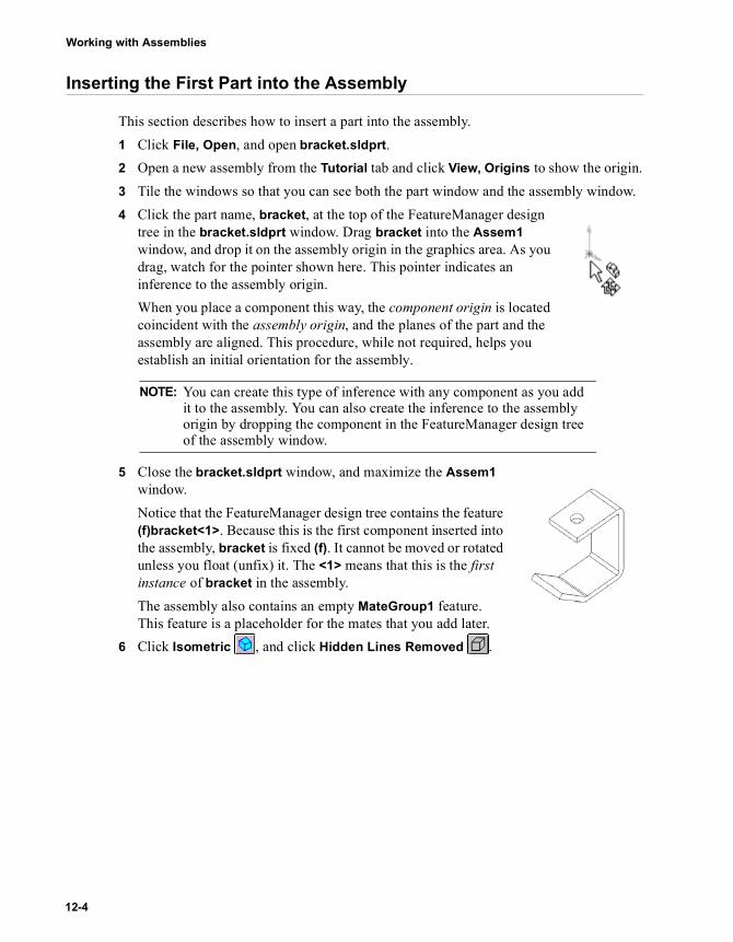
Working with Assemblies
Inserting the First Part into the Assembly
This section describes how to insert a part into the assembly.1 Click File, Open, and open bracket.sldprt.2 Open a new assembly from the Tutorial tab and click View, Origins to show the origin.3 Tile the windows so that you can see both the part window and the assembly window.4 Click the part name, bracket, at the top of the FeatureManager design
tree in the bracket.sldprt window. Drag bracket into the Assem1 window, and drop it on the assembly origin in the graphics area. As you drag, watch for the pointer shown here. This pointer indicates an inference to the assembly origin.When you place a component this way, the component origin is located coincident with the assembly origin, and the planes of the part and the assembly are aligned. This procedure, while not required, helps you establish an initial orientation for the assembly.
5 Close the bracket.sldprt window, and maximize the Assem1 window.Notice that the FeatureManager design tree contains the feature (f)bracket<1>. Because this is the first component inserted into the assembly, bracket is fixed (f). It cannot be moved or rotated unless you float (unfix) it. The <1> means that this is the first instance of bracket in the assembly. The assembly also contains an empty MateGroup1 feature. This feature is a placeholder for the mates that you add later.
6 Click Isometric , and click Hidden Lines Removed .
NOTE: You can create this type of inference with any component as you add it to the assembly. You can also create the inference to the assembly origin by dropping the component in the FeatureManager design tree of the assembly window.
12-4

Chapter 12 Assembly Mates
Bringing More Components into the Assembly
Another way to add components to the assembly is to drag them in from Windows Explorer.1 Start Windows Explorer (if it is not already running).2 Navigate to the \installation directory\samples\tutorial\universal_joint folder.3 Click each of the items listed below
individually, and drag it into the graphics area of Assem1. Place them approximately as shown.
• yoke_male.sldprt
• yoke_female.sldprt
• spider.sldprt4 Examine the FeatureManager design tree,
and expand each item to see the features used to make the components.Notice that each of the new components has the prefix (-) before its name, indicating that its location is under defined. You can move and rotate these components.
5 To collapse the entire FeatureManager design tree in one step, right-click Assem1 in the FeatureManager design tree and select Collapse Items.
6 Practice moving and rotating the individual components using the following tools on the Assembly toolbar:
7 Save the assembly as U-joint.sldasm.
Click Move Component, click one of the component’s faces, then move the component.Click Rotate Component, click one of the component’s faces, then rotate the component.Both the Move Component and Rotate Component tools remain active so that you can move other non-fixed components in succession.
yoke_male spider yoke_female
bracket
SolidWorks Educational Edition Getting Started 12-5
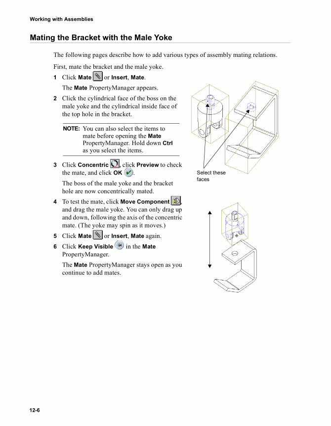
Working with Assemblies
Mating the Bracket with the Male Yoke
The following pages describe how to add various types of assembly mating relations.
First, mate the bracket and the male yoke.1 Click Mate or Insert, Mate.
The Mate PropertyManager appears.2 Click the cylindrical face of the boss on the
male yoke and the cylindrical inside face of the top hole in the bracket.
3 Click Concentric , click Preview to check the mate, and click OK .The boss of the male yoke and the bracket hole are now concentrically mated.
4 To test the mate, click Move Component , and drag the male yoke. You can only drag up and down, following the axis of the concentric mate. (The yoke may spin as it moves.)
5 Click Mate or Insert, Mate again.6 Click Keep Visible in the Mate
PropertyManager.The Mate PropertyManager stays open as you continue to add mates.
NOTE: You can also select the items to mate before opening the Mate PropertyManager. Hold down Ctrl as you select the items.
Select these faces
12-6

Chapter 12 Assembly Mates
7 Click the top inside face of the bracket and the top face of the male yoke.
8 Click Coincident in the Mate PropertyManager, click Preview, and click OK .The top of the yoke is now inserted into the bracket hole.
TIP: To select the top inside face of the bracket without rotating the bracket, right-click the top of the bracket, and click Select Other. Click N until the correct face is highlighted, then click Y.
Select these faces
SolidWorks Educational Edition Getting Started 12-7

Working with Assemblies
Mating the Male Yoke with the Spider
1 Select the inside faces of one pin hole on the male yoke and one spider pin hole.
2 Click Concentric , click Preview, and clickOK .The spider and the male yoke are now concentrically mated.
3 Select the flat spider face that contains the hole you selected in Step 1 and the inside face of the male yoke. Use Select Other or rotate the assembly if necessary.
4 Click Coincident , then click Preview. The spider should be placed inside the male yoke as shown.• If the mate looks correct, click OK .• If the mate looks wrong, click Undo, select the
correct faces, and click OK .5 Click Cancel to close the Mate PropertyManager.
NOTE: To move and rotate components while the Mate PropertyManager is open, use the Pan and Rotate View tools on the View toolbar. To exit from move or rotate mode, click the tool again or press Esc so you do not clear the Mate Settings list.
12-8

Chapter 12 Assembly Mates
Mating the Female Yoke and the Spider
1 Using the tools on the Assembly toolbar (see page 12-5), move and rotate the female yoke to approximately the position shown here.
2 Click Mate or Insert, Mate, then clickKeep Visible in the Mate PropertyManager.
3 Select the inside face of the pin hole of the female yoke and one of the visible spider pin holes.
4 Click Concentric , click Preview, and click OK .The spider and the female yoke are concentrically mated.
5 Select the flat spider face that contains the hole you used in Step 3, and the inside face of the female yoke.
6 Click Coincident , click Preview, and click OK .The female yoke should be positioned as shown. The rotation may be different in your assembly because it is based on the initial position of the two components before mating.
SolidWorks Educational Edition Getting Started 12-9
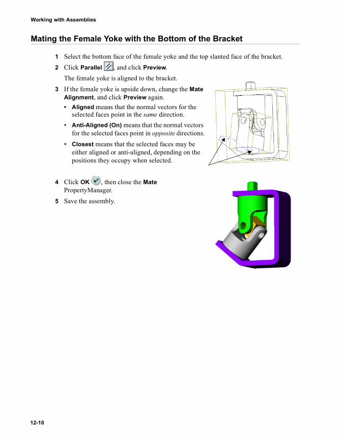
Working with Assemblies
Mating the Female Yoke with the Bottom of the Bracket
1 Select the bottom face of the female yoke and the top slanted face of the bracket.2 Click Parallel , and click Preview.
The female yoke is aligned to the bracket.3 If the female yoke is upside down, change the Mate
Alignment, and click Preview again.• Aligned means that the normal vectors for the
selected faces point in the same direction.• Anti-Aligned (On) means that the normal vectors
for the selected faces point in opposite directions.• Closest means that the selected faces may be
either aligned or anti-aligned, depending on the positions they occupy when selected.
4 Click OK , then close the Mate PropertyManager.
5 Save the assembly.
12-10

Chapter 12 Assembly Mates
Mating the Small Pins to the Female Yoke
Another way to add components to an assembly is to use the Insert menu.1 Click Insert, Component, From File, then navigate to installation
directory\samples\tutorial\universal_joint.2 Select u-joint_pin2.sldprt, then click Open.3 Click the pointer in the graphics area where you want to place the component.
The u-joint_pin2<1> component is added to the assembly.4 Click Mate or Insert, Mate, then click Keep Visible in the Mate
PropertyManager.5 Select the cylindrical face of the pin and an
inside face of a pin hole on the female yoke.6 Add a Concentric mate.
7 Select the end face of the pin and the outside face of the female yoke.
8 Click Tangent and click Preview. If the alignment is incorrect, change the Mate Alignment and click Preview again.You use Tangent (instead of Coincident) for this mate because one face is flat and the other face is cylindrical.
9 Click OK , then close the Mate PropertyManager.
10 Hold down Ctrl, then drag the u-joint_pin2<1> icon from the FeatureManager design tree into the graphics area.A copy of the component is added to the assembly, u-joint_pin2<2>.The <2> notation indicates the second instance of this part in the assembly.
11 Repeat steps 4 through 9 to mate the second instance of the pin to the other hole in the female yoke.
12 Save the assembly.
SolidWorks Educational Edition Getting Started 12-11

Working with Assemblies
Using SmartMates to Mate the Large Pin
For some mates, you can create mating relationships automatically using SmartMates. You can inference the geometry of existing components as you drag and drop new components into the assembly.
In this section, you create a concentric mate automatically. For more information about SmartMates, see the SolidWorks Online User’s Guide.1 Click File, Open, and open u-joint_pin1.sldprt.2 Tile the windows so that you can see the part and the assembly windows.3 Change the view orientation of the part to Isometric , if necessary.4 Change the view mode in the assembly window to Shaded , and change the view
orientation to Isometric . Zoom in on the pin hole in the male yoke.Shaded mode allows you to see the preview of SmartMates better.
5 Select the cylindrical face of the pin, and drag the pin into the assembly. Point at an inside face of the pin hole on the male yoke in the assembly window. (The pin may disappear behind the assembly.)When the pointer is over the pin hole, the pointer changes to . This pointer indicates that a concentric mate will result if the pin is dropped at this location. A preview of the pin snaps into place.If the preview indicates that you need to flip the alignment condition, press the Tab key to toggle the alignment(aligned/anti-aligned).
6 Drop the pin. A concentric mate is added automatically.
7 Close the u-joint_pin1.sldprt window, and maximize the assembly window.
Preview of pin
12-12
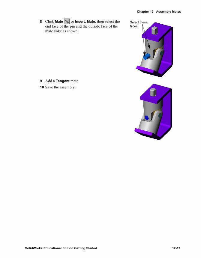
Chapter 12 Assembly Mates
8 Click Mate or Insert, Mate, then select the end face of the pin and the outside face of the male yoke as shown.
9 Add a Tangent mate.10 Save the assembly.
Select these faces
SolidWorks Educational Edition Getting Started 12-13

Working with Assemblies
Mating the Handle to the Assembly
1 Click Hidden Lines Removed .2 Drag crank-assy.sldasm from Windows Explorer and drop it into the assembly
window.3 Click Mate or Insert, Mate.4 Select the outside face of the crankshaft and the
cylindrical face of the male yoke boss (not the flat face on the boss).
5 Add a Concentric mate and click OK .6 Click Move Component , and drag the
crankshaft above the male yoke boss.7 Click Mate or Insert, Mate, and click
Keep Visible in the Mate PropertyManager.8 Click Hidden In Gray , then click Zoom to
Area and zoom in on the crankshaft and male yoke boss.
9 Select the flat face of the male yoke boss and the flat face on the inside of the crankshaft. Use Select Other to more easily select any hidden faces.
10 Add a Parallel mate.
12-14

Chapter 12 Assembly Mates
11 Select the bottom face of the crankshaft and the top face of the bracket. Add a Coincident mate.
12 Close the Mate PropertyManager, and save the assembly.
13 Click Isometric , then click Shaded .The completed assembly should appear as shown.
SolidWorks Educational Edition Getting Started 12-15

Working with Assemblies
14 Click the beside MateGroup1 of the assembly (not the crank-assy sub-assembly) to see the mates.
Each mate is identified by the type and a number, and the names of the components involved are shown. As you pause over each mate, the entities involved are highlighted in the graphics area.You can rename the mates in the same way that you rename the features of a part, if desired.
Rotating the Crank Handle
You can turn the crank of the assembly by selecting the sub-assembly, and moving the handle.1 Click Move Component . 2 Click a face on one of the components
of the crank sub-assembly.3 Drag the pointer vertically in the
graphics area.The crank turns and rotates the male and female yokes. All of the mating relationships are maintained.
NOTE: If you have added or deleted mates, the names of the mates in your assembly may differ from those shown here.
rotate crank
12-16

Chapter 12 Assembly Mates
Exploding the Assembly
You can create an exploded view of the assembly. An exploded view consists of one or more explode steps. In this section, you define the first step in an exploded view.1 Click Insert, Exploded View.2 In the Assembly Exploder dialog box, in the Step
editing tools box, click New .The Assembly Exploder dialog box expands.
3 Click a vertical edge on the bracket to set the Direction to explode along.
If the preview arrow is pointing down, select the Reverse direction check box.
4 Click a face of a component of the crank assembly in the graphics area, or click the crank-assy component in the FeatureManager design tree for the Components to explode box.
5 Examine the contents of the boxes under Step parameters. Make sure that the Entire sub-assembly option is selected. If you need to make any other changes:• Select and delete the contents of the Components to explode box.
– or –• Click the Components to explode box, right-click in the graphics area, select Clear
Selections, and select again.6 Click Apply .
Notice the arrow-shaped handle in the graphics area.7 Drag the handle up and down until the crank assembly is positioned at a reasonable
distance from the bracket. (You can specify the position by using the Distance box if you prefer.)
8 Click Apply again to confirm the new distance value in the step.Do not click OK yet. Leave the Assembly Exploder dialog box open, so you can continue adding steps to the exploded view. You click OK only when all the steps in the view are completed.
SolidWorks Educational Edition Getting Started 12-17

Working with Assemblies
Adding Explode Steps
Now add explode steps for other components.1 Click New to create the next explode step.2 Click a horizontal edge on the bracket.3 Click the male yoke, the female yoke, the spider
and the pins (either in the graphics area or the FeatureManager design tree).
4 Verify the Step parameters, and click Apply .
5 Adjust the distance as desired. 6 Click Apply .7 Click OK to save the exploded view with its two
steps.8 Click a blank area in the graphics area to deselect all the selected items.9 To collapse the assembly, restoring it to its previous condition, right-click anywhere in
the graphics area and select Collapse.
12-18

Chapter 12 Assembly Mates
Editing the Exploded View
You can edit the explode steps, or add new ones if needed. You access the exploded view from the ConfigurationManager tree.1 Click the ConfigurationManager tab to change to the configuration view.2 Double-click Default, or click the to expand the view.
If you are asked to confirm showing the configuration, click OK.3 Double-click ExplView1 to explode the assembly again (or right-click ExplView1, and
select Explode).4 Right-click ExplView1, and select Edit Definition.5 Using the Previous Step and Next Step buttons
, or the Explode steps list, review each of the steps in the exploded view. Edit any step as desired, then click Apply before editing or adding another step.
6 Click New to create a new explode step, then practice exploding more of the assembly. Remember to click Apply each time you complete a step.
7 When you are satisfied with the entire exploded view, click OK.
8 To collapse the entire assembly, right-click the assembly name at the top of the ConfigurationManager tree, and select Collapse.
9 Save the assembly. You will use this assembly later in Chapter 16, “Bill of Materials.”
SolidWorks Educational Edition Getting Started 12-19

13 Advanced Design Techniques
Suppose that you want to design a hinge assembly that you can modify easily to make similar assemblies. You need an efficient way to create two matching hinge pieces and a pin for a variety of hinge assembly sizes.
Some analysis and planning can help you develop a design that is flexible, efficient, and well defined. You can then adjust the size as needed, and the hinge assembly will still satisfy the design intent.
This chapter discusses:
� Analyzing the assembly to determine the best approach
� Using a layout sketch
� Suppressing features to create part configurations
� Creating a new part in the context of the assembly
This chapter assumes that you know how to perform basic assembly operations, such as moving and rotating components, and adding mates. (These topics are covered in Chapter 3, “Assembly Basics”, and Chapter 12, “Assembly Mates”)
SolidWorks Educational Edition Getting Started 13-1

Working with Assemblies
Analyzing the Assembly
Successful customers tell us that the key to using the SolidWorks software effectively is planning. By performing a careful analysis, you can design better, more flexible, and more functional models. Before you begin an assembly, consider the following:
� Consider dependencies between the components of an assembly. This will help you decide on the best approach:• Using bottom-up design, you build the parts independently, then insert them into the
assembly.• Using top-down design, you may begin with some ready-made parts. Then you
create other components in the context of the assembly. You reference the features of some components of the assembly to drive the dimensions of the other components.
� Identify the features that make up each individual part. Understand the dependencies between the features of each part. Look for patterns, and take advantage of symmetry whenever possible.
� Consider the order in which the features are created, and keep in mind the manufacturing processes that will be used to make the parts.
Dependencies in the Assembly
The hinge pieces
The two pieces of the hinge are alike: the size and thickness of the body, the barrel that receives the pin, and the placement of the screw holes. The only differences between the two pieces are the cuts and tabs on the barrel, where they fit together.
There are several ways to approach this task:
� Copy. You could make one piece, make a copy of it, then modify the copy as needed for the second piece. However, if you wanted to make another assembly in a different size, you would need to edit both pieces. This is not the best approach; it leaves room for error because the pieces are independent of each other.
� Derive. You could create a base part consisting of only the common elements, then derive the two pieces from it (using Insert, Base Part or Insert, Mirror Part). To make changes to the common dimensions, you edit the original, and the derived parts are updated automatically. This behavior is useful in some circumstances, but it has drawbacks for this application. You do not have access to the driving dimensions of the original part when editing a derived part, so you cannot reference those dimensions when creating the features that differ.
13-2
Chapter 13 Advanced Design Techniques
� Configure. The method that you use for this example is to make two different configurations of the same part. This is the best way to ensure that you always have matching pieces, because a single part document is used to create the two pieces. The part document contains all the possible features to be used. Then you create configurations by suppressing selected features, removing them from the active configuration.
The pin
You need to know the dimensions of the barrel to create a pin that is exactly the right size for the assembly. By creating the pin in the context of the assembly, you can accomplish this for any size hinge.
Conclusion
For this assembly, it makes sense to use a combination of design methodologies. First, design the hinge pieces, including the necessary configurations, and insert them in an assembly (bottom-up design). Then design the pin in the context of the assembly (top-down design), referencing the model geometry of the hinge pieces as necessary.
Analysis of the Individual PartsNow that you understand the dependencies between components, take a look at the parts individually.
The common features of the hinge pieces
The base feature is a flat rectangle, with a round barrel along one edge. The diameter of the barrel is dependent on the thickness of the base. Each piece has four countersunk holes. The position of the holes is symmetric with respect to the midpoint of the long edge. As the size of the hinge changes, you want the holes to remain properly spaced along the length and width.
The different features of the hinge pieces
The cuts (and corresponding tabs) along the barrel are the features that distinguish the two pieces. One piece has three cuts, and the other has two cuts. The placement is symmetric with respect to the midpoint of the long edge. Each cut should be slightly larger than the corresponding tab, so the hinge will not bind when assembled.
The pin
The pin is dependent on the hinge pieces for its length and diameter dimensions. The domed head of the pin should match the outer diameter of the barrel.
SolidWorks Educational Edition Getting Started 13-3

Working with Assemblies
Construction OrderOutline your construction plan, including the features you will use and the order in which to create them.
1 Base feature – extrude as a thin feature. Because the part has symmetric features, use a mid-plane extrusion. Then you can use the mid-plane as a plane of symmetry for mirroring other features.
2 Barrel – sweep a circular profile along the long model edge. Then extrude a cut, concentric with the boss.
3 Countersunk holes – use the Hole Wizard to create a complex hole profile, then use equations and mirroring to position several copies.
4 Cuts for tabs – create a layout sketch, referencing the dimensions of the base. Use the sketch to extrude two different cut features, one with three tabs, one with two tabs.
5 Configurations – define the two configurations used in the assembly by suppressing one cut feature in each configuration.
6 Assembly – insert and mate the hinge pieces (one of each configuration).7 Pin – insert a new part while in the assembly. Reference the geometry of the hinge
piece to sketch a profile and a path. Then use a sweep to create the base feature.8 Pin head – convert the barrel profile to create a sketch, then extrude it. Finally, add a
dome to the flat surface of the head.
A Final WordThis may seem like a great deal of planning to develop a simple assembly. However, it is a worthwhile exercise if it helps you discover the best approach to building the parts before you start designing them. By thoroughly analyzing the issues before you begin, you can create a flexible, fully parametric model. When you change any of its parameters, the others update accordingly.
For more examples that showcase design intent and implementation, view the SolidWorks Design Portfolio by clicking Help, Design Portfolio.
13-4

Chapter 13 Advanced Design Techniques
Creating the Basic Hinge Piece
1 Open a new part from the Tutorial tab and open a sketch on the Front plane.2 Sketch a vertical line and dimension it to 60mm in length.3 Click Extruded Boss/Base or Insert, Base, Extrude to extrude the sketch:
a) Under Direction 1, do the following:• Set End Condition to Mid Plane.• Set Depth to 120mm.
b) Under Thin Feature, do the following:• Leave Type as One-Direction.• Set Direction 1 Thickness to 5mm.
c) Click OK .4 Open a sketch on the narrow vertical face. Sketch a circle at
the upper edge, with its center at the front vertex. 5 Add a coincident relation between the edge of the circle and
the back vertex to fully define the sketch. Close the sketch.
6 Click Sweep or Insert, Boss, Sweep. Select the circle as the Profile . Select the Path box in the Boss-Sweep PropertyManager and click one of the long model edges. Click OK .
7 Cut a hole through the barrel:a) Open a sketch on the narrow face.b) Sketch and dimension a small circle as shown, and add a
concentric relation to the outside edge of the barrel.c) Click Extruded Cut or Insert, Cut, Extrude. Set End
Condition to Through All, and click OK .8 Save the part as Hinge.sldprt.
SolidWorks Educational Edition Getting Started 13-5

Working with Assemblies
Adding the Screw Holes
In this section, you add holes for screws. To position each hole, one dimension is fixed, and the other is driven by an equation. 1 Click the large model face, then click Hole Wizard on the Features toolbar, or click
Insert, Features, Hole, Wizard.2 On the Countersink tab of the Hole Definition dialog box, set the following values:
• Standard to Ansi Metric.• Size to M8.• End Condition & Depth to Through All.
3 Click Next, then click on the large model face to add the center point for a second hole.
4 Click Select and drag the points to the approximate location on the face shown here. Click Finish.
5 Right-click the under defined sketch containing the points for CSK for M8 Flat Head Machine Screw1, and select Edit Sketch. Dimension the points to the edges of the hinge as shown. Do not close the sketch.
6 Add an equation to control the location of one of the points:a) Click Equations on the Tools toolbar or Tools,
Equations, then click Add.b) Clear the default text in the New Equation dialog
box, if necessary.c) Select the 30mm dimension, then type =.d) Double-click the base to expose its dimensions then select the 60mm dimension.e) Type /2 to complete the dimension and click OK to close the New Equation dialog
box.This sets the distance between the point and the bottom edge to one-half the height (60mm) of the hinge.
Hole1 Hole2
13-6

Chapter 13 Advanced Design Techniques
7 Add an equation to control the location of the other point:a) Click Add in the Equations dialog box.b) Clear the default text in the New Equation dialog box, if necessary.c) Select the 40mm dimension then type =.d) Double-click the base to expose its dimensions then select the 120mm dimension.e) Type /3 to complete the dimension and click OK to close the New Equation dialog
box.The distance between the point and the side edge equals one-third of the length (120mm) of the hinge.
8 Click OK to close the Equations dialog box, then close the sketch.9 Mirror the holes:
a) Click Mirror Feature on the Features toolbar, or click Insert, Pattern/Mirror, Mirror Feature.
b) Click the Front plane in the FeatureManager design tree.Front appears in the Mirror Face/Plane box.
c) Click the hole feature in either the FeatureManager design tree or in the graphics area.CSK for M8 Flat Head Machine Screw1 appears in the Features to mirror box.
d) Click OK.10 Save the part.
Creating a Layout Sketch for the Cuts
The layout sketch you create in this section divides the length of the hinge into five equal parts. Using equations and mirroring ensures that the five parts remain equal when you change the overall length of the hinge. You use this layout as a guide for making the cuts in the sections that follow.1 Open a sketch on the large model face, and name it layout
for cuts.2 Click the lower edge of the sweep feature and click Offset
Entities .a) Set Offset Distance to 1mm.b) Select the Reverse check box if necessary to offset
below the selected edgec) Click to clear the Select chain check box if
necessary.d) Click OK .
SolidWorks Educational Edition Getting Started 13-7

Working with Assemblies
3 Select the edges shown, then click Convert Entities .
4 Click Extend in the Sketch Tools toolbar, or click Tools, Sketch Tools, Extend, then click the converted edges. Each vertical line is extended to meet the nearest sketch entity, in this case, the offset horizontal line.
5 Sketch a horizontal line to connect the two converted edges across the top.
6 Sketch two vertical lines as shown, and dimension them. As you sketch the lines, be sure that you do not inference the geometry of the holes. Also, because the dimensions will be driven by an equation, the values of the dimensions do not matter at this time.
7 Add the equations:a) Click the FeatureManager tab , right-click the
Equations folder , and select Add Equation.b) Add equations that set each dimension to one-fifth of the dimension of the overall
length."D2@layout for cuts" = "D1@Base-Extrude-Thin" / 5"D3@layout for cuts" = "D1@Base-Extrude-Thin" / 5
c) Click OK to close the Equations dialog box.8 Sketch a vertical centerline across the
midpoint of the part. Select the two vertical lines and the centerline, and clickMirror . The sketch is complete and should be fully defined.
9 Close the sketch.10 Save the part.
Click these edges
13-8

Chapter 13 Advanced Design Techniques
Cutting the Hinge (3Cuts)
Now you can reference the layout for cuts sketch to create the first set of cuts. Because each cut should be slightly wider than the corresponding tab on the other half of the hinge, you use offsets from the layout sketch entities.1 Open a sketch on the large model face.2 Click the bottom line in the layout sketch, and click Convert Entities . In the
Resolve Ambiguity box, click closed contour, and click OK. This copies the entire outside contour into the current sketch.
3 Click one of the vertical lines near the edge of the part, click Offset Entities and do the following:a) Set Offset Distance to 1mm.b) Select the Reverse check box if
necessary to offset the line towards the middle of the part.
c) Make sure that Select chain is not selected, and click OK .4 Repeat for the vertical line near the opposite edge of the part.5 Click one of the vertical lines near the
center of the part, and offset the line by 1mm toward the outside of the part (making the center cut wider). Repeat for the remaining vertical line.
6 Click Trim , then trim the horizontal lines as indicated, leaving three closed rectangles.
7 Click Extruded Cut or Insert, Cut, Extrude. Select Through All as End Condition for both Direction 1 and Direction 2.
8 Click OK .9 Rename the cut feature 3Cuts.10 Save the part.
Segments in current sketch
Trim these segments
SolidWorks Educational Edition Getting Started 13-9

Working with Assemblies
Cutting the Hinge (2Cuts)
Now you use the same methods to create the cuts for the other half of the hinge.1 Roll back the design to the 3Cuts feature
by dragging the rollback bar to just below the layout for cuts sketch.
2 Repeat Steps 1 and 2 from the previous section.
3 Click one of the vertical lines near the edge of the part, click Offset Entities , and do the following:a) Set the Offset Distance to 1mm.b) Offset it towards the outside of the
part.c) Make sure that Select chain is not
selected, and click OK . 4 Repeat for the vertical line near the
opposite edge of the part.5 Click one of the vertical lines near the center of the part, and offset it by 1mm toward
the middle of the part. Repeat for the remaining vertical line.6 Click Trim . Trim the three segments
at each end and the two segments in the middle, leaving two closed rectangles.
7 Extrude the cut as described in the previous section.
8 Rename this cut feature 2Cuts.9 Right-click the layout for cuts sketch,
and select Hide.
Rollback bar
Segments in current sketch
Trim these segments
13-10

Chapter 13 Advanced Design Techniques
Creating the Part Configurations
Roll the design forward by dragging the rollback bar all the way to the bottom of the FeatureManager design tree.
The part now has the entire barrel removed by the two cut features. This is the default configuration, which includes all the features. In this section, you make two more configurations of the part by suppressing selected features.
The OuterCuts configuration1 Click the ConfigurationManager tab at the bottom of the window to change to the
ConfigurationManager view.2 Right-click the part name at the top of the ConfigurationManager tree, and select Add
Configuration.3 Enter a Configuration Name, such as OuterCuts, in the box and click OK.4 Click the FeatureManager tab at the bottom of the window to switch back to the
FeatureManager view. Notice the configuration name beside the part name at the top of the tree: Hinge (OuterCuts).
5 Click the 2Cuts feature, then click Suppress on the Features toolbar, or click Edit, Suppress.The 2Cuts feature is unavailable in the FeatureManager design tree, and is inactive in the current configuration.
The InnerCuts configuration
1 Repeat Steps 1 and 2 from the previous section.2 Enter a Configuration Name, such as InnerCuts, in the box, then click OK. 3 Switch back to the FeatureManager view. Notice the configuration name: Hinge
(InnerCuts).4 Click the 3Cuts feature, then click Suppress .
Now both cuts are suppressed.5 Click the 2Cuts feature, then click Unsuppress on the Features toolbar, or click
Edit, Unsuppress. The 3Cuts feature is unavailable in the FeatureManager design tree, and the 2Cuts feature is active in the current configuration.
6 Save the part.
SolidWorks Educational Edition Getting Started 13-11

Working with Assemblies
Inserting and Mating the Parts in an Assembly
Now you can begin creating the assembly.1 Open a new assembly from the Tutorial tab and click View, Origins to show the
origins. 2 Tile the windows, and drag the Hinge from the top of the FeatureManager design tree
of the open part window into the assembly window. Inference the assembly origin while you place the component to align the planes of the assembly and the component.
3 Maximize the assembly window.4 Right-click the component, and select Component Properties. Under Referenced
configuration, notice that Use named configuration and InnerCuts are selected by default. InnerCuts is the active configuration name of the part added in Step 2. Click OK to close the dialog box.
5 Hold down Ctrl, then drag the Hinge from either the graphics area or the FeatureManager design tree, and drop it beside the first one to create another instance. Use Move Component and Rotate Component
to turn the second Hinge so that it faces the first one.
6 To change the named configuration, edit the component properties of the second Hinge. Click Use named configuration, select OuterCuts from the list, and click OK.
7 Create a Coincident mate between the narrow front faces of the components. Create a Concentric mate between the cylindrical faces of the barrels.
Coincident mate Concentric mate
13-12

Chapter 13 Advanced Design Techniques
You should be able to open and close the hinge assembly using Move Component .
8 Save the assembly as Hinge.sldasm.
Creating a New Part in the Assembly
Now you add the pin. The pin references the inner diameter of the barrel and the overall length of the hinge pieces. Once you reference an entity of one part (the barrel) to create an entity in another part (the pin), you create a reference in the context of the assembly. If you modify the referenced entity, the new entity updates to reflect that change.1 Click Insert, Component, New Part. Select a new part from the Tutorial tab. Enter a
name for the new component, such as Pin.sldprt, and click Save.The pointer changes to .
2 Click the narrow model face on the front of the assembly. The new part will be positioned on this face, with its location fully defined by an InPlace mate.A sketch is opened automatically on the selected face. Notice that Edit Part in the Assembly toolbar is selected, and that the pin component is displayed in pink in the FeatureManager design tree.
3 Click the inner circular edge of the barrel, then offset it to the inside by 0.25mm.
4 Exit the sketch.
SolidWorks Educational Edition Getting Started 13-13
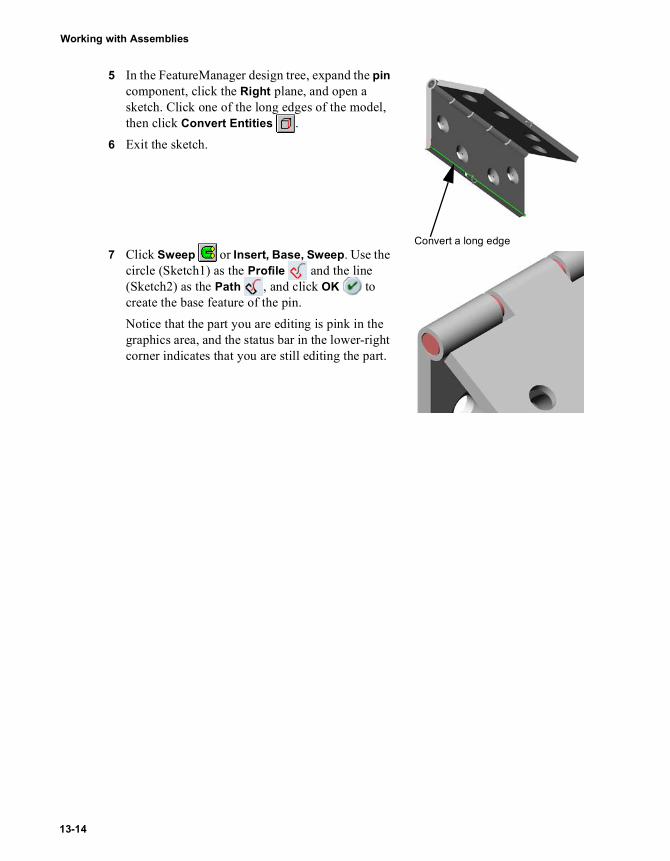
Working with Assemblies
5 In the FeatureManager design tree, expand the pin component, click the Right plane, and open a sketch. Click one of the long edges of the model, then click Convert Entities .
6 Exit the sketch.
7 Click Sweep or Insert, Base, Sweep. Use the circle (Sketch1) as the Profile and the line (Sketch2) as the Path , and click OK to create the base feature of the pin.Notice that the part you are editing is pink in the graphics area, and the status bar in the lower-right corner indicates that you are still editing the part.
Convert a long edge
13-14

Chapter 13 Advanced Design Techniques
Adding a Head to the Pin
Now reference the barrel of the hinge to create the head of the pin.1 Open a sketch on the flat end of the pin, and sketch a circle anywhere.2 Select the circle and the outer circular edge of the barrel,
and add a Coradial relation.
3 Click Extruded Boss/Base . Set End Condition to Blind, set Depth to 3mm, and click OK .
4 To add a dome to the head of the pin, click Dome on the Features toolbar, or click Insert, Features, Dome.
5 Click the flat face of the pin, set Height to 3mm. Observe the preview of the dome. Click OK. This completes the pin.
6 Right-click in the graphics area, and select Edit Assembly: Hinge. Alternatively, you can click Edit Part on the Assembly toolbar to return to editing the assembly.
7 Save the assembly.
SolidWorks Educational Edition Getting Started 13-15

Working with Assemblies
Changing the Color of a Component
For easier viewing, you can change the color of assembly components.1 Click one of the assembly components in either the
FeatureManager design tree or in the graphics area, then click Edit Color .
2 Choose a color from the palette, then click OK.
Editing the Hinge Components
Now you can make this same hinge assembly in a different size.1 In the FeatureManager design tree, expand the hinge component that uses the
InnerCuts configuration. Double-click the Base-Extrude-Thin feature to display its dimensions.
2 Double-click any of the dimensions. The Modify dialog box appears. 3 Change the dimension value, and make sure that All configurations is selected.4 Click to close the Modify dialog box.
If desired, repeat Steps 2 through 4 to change another value.5 Click Rebuild or Edit, Rebuild.
All of the components in the assembly update automatically. (If you see a message indicating that the pin has rebuild errors, click Rebuild again.)
13-16

14
More about Assemblies
You can do more with assemblies than what is shown in the examples in this guide. The following pages highlight some additional SolidWorks functionality in assemblies. For more information, see the SolidWorks Online User’s Guide.
This chapter briefly describes SolidWorks functionality in the following areas:
� Additional Mate Types
� Sub-assemblies
� Parts Created in the Context of an Assembly
� Assembly Simplification
� Interference Detection
SolidWorks Educational Edition Getting Started 14-1

Working with Assemblies
Arranging Components
Additional Mate Types
The examples in this book show only a subset of the available mates. There are over seventy combinations of entities and mate types available. You can mate cones, cylinders, extrusions, lines, planes, points, and spheres to other entities. You can add angle, coincident, concentric, distance, parallel, perpendicular, symmetry, and tangent mates.
SmartMates
In addition to the SmartMates you added in Chapter 12, “Assembly Mates,” you can add other types of SmartMates. You can add feature-based mates between conical or cylindrical features. You can add a pattern-based mate to align two components using the circular patterns in the components.
Symmetry Mates
A symmetry mate forces two similar entities to be symmetric about a plane or planar face of a component.
In the illustration, the two highlighted faces are symmetric about the highlighted plane. Notice the two components are upside down with respect to one another. That is because the highlighted faces only are symmetric, not all of the faces of both components.
Cam-Follower Mates
A cam-follower mate is a type of tangent or coincident mate. It allows you to mate a cylinder, plane, or point to a series of tangent extruded surfaces, such as you would find on a cam.
Components to mate Result of pattern-based mate
14-2
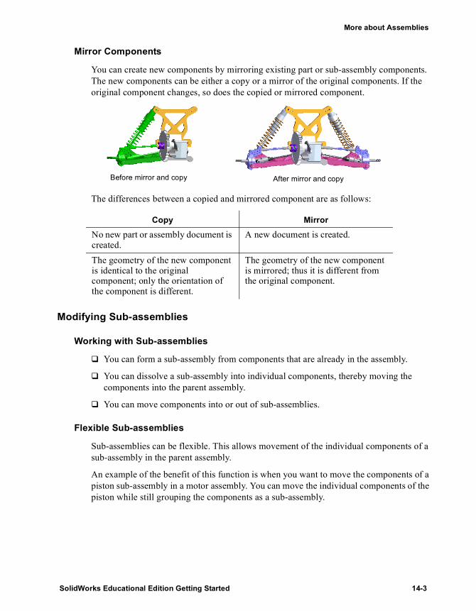
More about Assemblies
Mirror Components
You can create new components by mirroring existing part or sub-assembly components. The new components can be either a copy or a mirror of the original components. If the original component changes, so does the copied or mirrored component.
The differences between a copied and mirrored component are as follows:
Modifying Sub-assemblies
Working with Sub-assemblies
� You can form a sub-assembly from components that are already in the assembly.
� You can dissolve a sub-assembly into individual components, thereby moving the components into the parent assembly.
� You can move components into or out of sub-assemblies.
Flexible Sub-assemblies
Sub-assemblies can be flexible. This allows movement of the individual components of a sub-assembly in the parent assembly.
An example of the benefit of this function is when you want to move the components of a piston sub-assembly in a motor assembly. You can move the individual components of the piston while still grouping the components as a sub-assembly.
Copy MirrorNo new part or assembly document is created.
A new document is created.
The geometry of the new component is identical to the original component; only the orientation of the component is different.
The geometry of the new component is mirrored; thus it is different from the original component.
Before mirror and copy After mirror and copy
SolidWorks Educational Edition Getting Started 14-3

Working with Assemblies
Working with Parts within an Assembly
Component Patterns
You can define a pattern for placing components in an assembly in much the same way as you define a feature pattern in a part. You can also place a pattern of components in an assembly based on a feature pattern of the assembly or of an existing component. For example, you can place a number of brackets matching a pattern of holes on an object.
Assembly Features
While in an assembly, you can create cut or hole features that exist in the assembly only. You determine which of the assembly components you want the feature to affect. This is useful for creating cuts or holes that are added after the components are assembled.
Smart Fasteners
With a single command, you can insert bolts and screws from an existing library of hardware into holes in your assembly. The program determines the appropriate type, size, and length of the fastener for each series of holes. It also allows you to add washers and nuts as needed.
14-4

More about Assemblies
Layout Sketches
You can design an assembly from the top-down using layout sketches. You can construct one or more sketches showing where each assembly component belongs. Then, you can create and modify the design before you create any parts. In addition, you can use the layout sketch to make changes in the assembly at any time.
Joining Parts
You can join two or more parts to create a new part. The join operation removes surfaces that intrude into each other’s space, and merges the part bodies into a single solid volume.
Weld Beads
You can add a variety of weld types to an assembly. The software prompts you for the weld type, the surface type, and the surfaces you want to weld together. When you create a weld, a weld symbol is automatically attached to the weld bead component in the assembly.
Simplifying Assemblies
Assembly Envelopes
You can select components based on their positions with respect to an assembly envelope. An assembly envelope is a reference component, and it is ignored in global assembly operations (Bill of Materials, Mass Properties, and so on.) You can perform various editing operations (hide, suppress, copy, or delete) on components that are inside, outside, or crossing the assembly envelope.
SolidWorks Educational Edition Getting Started 14-5

Working with Assemblies
Component Selection by Properties
You can select components for editing operations based on properties. Once you select those components that match the properties you specify, you can perform the desired editing operation, such as suppress, hide, or copy.
Assembly Configurations
You can create configurations in assemblies to do the following:
� Toggle the visibility or suppression state of components.
� Place components in different locations.
� Switch the configuration of the components.
� Modify the dimensions or suppression states of assembly features and mates.
Preventing Interference Between ComponentsIn a complex assembly, it may be difficult to visually determine whether components interfere with each other. In some cases, it becomes more difficult when you move components in the assembly. You can use the following tools to determine interference:
� Interference Detection. You can determine the interference between components and examine the resulting interference volumes.
� Collision Detection. You can detect collisions with other components when moving or rotating a component.
� Dynamic Clearance. You can dynamically detect the clearance between components when moving or rotating a component. As you move or rotate a component, a dimension appears indicating the minimum distance between the selected components, as shown in the illustration. Additionally, you can prevent two components from moving within a specified distance of one another.
14-6

Working with Drawings and Detailing
Advanced Drawings and Detailing
Bill of Materials
More about Drawings and Detailing
SolidWorks Educational Edition Getting Started

15 Advanced Drawings and Detailing
Chapter 4, “Drawing Basics” introduced the Standard 3 Views and Named Views. In this chapter, you learn about using SolidWorks software to create the following:
� Section View
� Detail View
� Ordinate Dimensions
� Annotations
� Exploded View
� Notes
SolidWorks Educational Edition Getting Started 15-1

Working with Drawings and Detailing
Starting the Drawing with Named Views
Open a drawing and insert a Named view.1 Open a new drawing from the Tutorial tab. 2 Right-click anywhere on the drawing sheet and select Properties.
The Sheet Setup dialog box appears.3 Change Scale to 2:1, then click OK.4 Click Named View or Insert, Drawing View, Named View.
The Named View PropertyManager appears with a message listing four methods for selecting a model.
5 Right-click in the graphics area, and select Insert From File. 6 In the Insert Component dialog box, navigate to connector.sldprt in directory
\installation directory\samples\tutorial\handle, and click Open.The Named View PropertyManager displays the View Orientation list.
7 Select *Right from the list and click to place the view at the upper left of the drawing.
8 Repeat steps 4 through 6. Select *Isometric from the View Orientation list and place this view at the lower left of the drawing.
9 Click Save .The Save As dialog box appears with connector.slddrw as the default name.
10 Type Adv-Drawing, then click Save.If you see a message asking if you want to update any referenced models, click Yes.
NOTE: You can change the view orientation at any time by selecting the view and double-clicking a different item from the View Orientation list.
If not all the lines appear as in the figure below, right-click the view and select Tangent Edge, Tangent Edges Visible.
15-2

Chapter 15 Advanced Drawings and Detailing
Adding a Section View
You add a Section View by cutting a view with a section line.1 Activate the view at the top left.
2 Click Section View on the Drawing toolbar, or click Insert, Drawing View, Section.The Section View PropertyManager appears, and the pointer changes to , indicating that the Line tool is active.
3 Hold the pointer over the center of the part until the pointer changes to indicating that the pointer is exactly on the temporary axis. Sketch a line vertically through the part. As you move the pointer, a preview of the view position is displayed. By default, the view is aligned in the direction of the cut.
4 Click in the graphics area to place the view to the right of the original view.Notice the arrows indicating the direction of the cut. You can double-click the section line, or select the Change direction check box in the PropertyManager, to reverse the direction of the arrows, if necessary.
NOTE: The border of an activated view is a shadowed box. A view activates automatically if the option Dynamic drawing view activation is selected in Tools, Options, System Options, Drawings. To activate a view manually, double-click the view or right-click the view and select Activate View.
NOTE: To sketch the section line with the Centerline tool, or to create a multi-line section view, sketch the section line before selecting the Section View command.
TIP: If you reverse the direction of the section line arrows, the Section View is marked with a crosshatch pattern. This crosshatch indicates that the view is out of date. Right-click the view and select Update View to update the view only, or click Rebuild to rebuild the entire drawing.
SolidWorks Educational Edition Getting Started 15-3
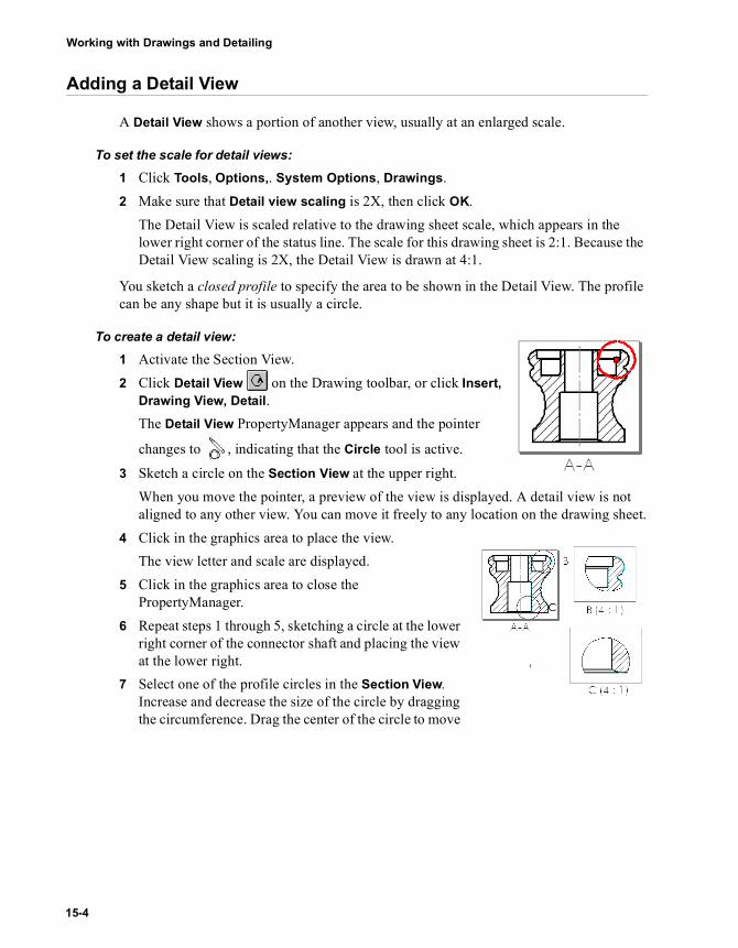
Working with Drawings and Detailing
Adding a Detail View
A Detail View shows a portion of another view, usually at an enlarged scale.
To set the scale for detail views:1 Click Tools, Options,. System Options, Drawings.2 Make sure that Detail view scaling is 2X, then click OK.
The Detail View is scaled relative to the drawing sheet scale, which appears in the lower right corner of the status line. The scale for this drawing sheet is 2:1. Because the Detail View scaling is 2X, the Detail View is drawn at 4:1.
You sketch a closed profile to specify the area to be shown in the Detail View. The profile can be any shape but it is usually a circle.
To create a detail view:1 Activate the Section View.2 Click Detail View on the Drawing toolbar, or click Insert,
Drawing View, Detail.The Detail View PropertyManager appears and the pointer
changes to , indicating that the Circle tool is active.
3 Sketch a circle on the Section View at the upper right.When you move the pointer, a preview of the view is displayed. A detail view is not aligned to any other view. You can move it freely to any location on the drawing sheet.
4 Click in the graphics area to place the view.The view letter and scale are displayed.
5 Click in the graphics area to close the PropertyManager.
6 Repeat steps 1 through 5, sketching a circle at the lower right corner of the connector shaft and placing the view at the lower right.
7 Select one of the profile circles in the Section View. Increase and decrease the size of the circle by dragging the circumference. Drag the center of the circle to move
15-4

Chapter 15 Advanced Drawings and Detailing
the circle. Notice that the Detail View changes as the circle changes.
Inserting Ordinate Dimensions
To insert ordinate dimensions:1 Click Dimension , right-click in the graphics area and select Ordinate Dimension
from the shortcut menu, or click Tools, Dimensions, Ordinate.2 In the Section View, click the bottom horizontal line.
The first line you click becomes the zero position. Its label is 0. The other dimensions are calculated from this position.
3 Click again to place the ordinate.4 Click the other horizontal lines in the view.
The leaders jog automatically to prevent overlapping text. You can drag the dimensions left and right as a group.
To modify the ordinate dimensions:
1 Click Select , then right-click the top dimension and select Display Options, Jog.The dimension is selected, and handles appear on the leader.
2 Drag the dimension (not the handles) upwards. The dimensions remain aligned vertically.
3 Right-click the second dimension (20) and select Display Options, Jog.The check mark next to Jog is cleared and the jog in the leader is straightened.
NOTE: The view label letter increments automatically. To set the label letter for the next view, right-click the graphics area (outside the drawing views) and select Properties. Edit the text in Next view label.
To edit the current view label, select the Detail View or its circle. In the Detail View PropertyManager, you can edit the label text and other properties of the label, profile, and view.
SolidWorks Educational Edition Getting Started 15-5

Working with Drawings and Detailing
To remove the chain arrows:
1 Right-click one of the dimensions in the ordinate group, and select Properties.
2 Clear the Display as chain dimension check box.3 Click OK.
To add other dimensions to the drawing:1 Click Dimension then click the lines to be dimensioned.2 Click to place the dimension.
NOTE: The dimensions that you add to drawings are reference dimensions. They are gray and appear in parentheses. You cannot edit the values. However, the values of reference dimensions change when the model dimensions change.
15-6
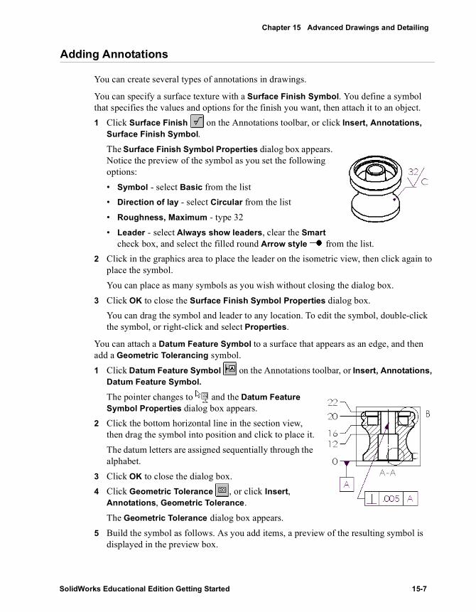
Chapter 15 Advanced Drawings and Detailing
Adding Annotations
You can create several types of annotations in drawings.
You can specify a surface texture with a Surface Finish Symbol. You define a symbol that specifies the values and options for the finish you want, then attach it to an object.1 Click Surface Finish on the Annotations toolbar, or click Insert, Annotations,
Surface Finish Symbol.The Surface Finish Symbol Properties dialog box appears. Notice the preview of the symbol as you set the following options:• Symbol - select Basic from the list• Direction of lay - select Circular from the list• Roughness, Maximum - type 32• Leader - select Always show leaders, clear the Smart
check box, and select the filled round Arrow style from the list.2 Click in the graphics area to place the leader on the isometric view, then click again to
place the symbol.You can place as many symbols as you wish without closing the dialog box.
3 Click OK to close the Surface Finish Symbol Properties dialog box.You can drag the symbol and leader to any location. To edit the symbol, double-click the symbol, or right-click and select Properties.
You can attach a Datum Feature Symbol to a surface that appears as an edge, and then add a Geometric Tolerancing symbol.1 Click Datum Feature Symbol on the Annotations toolbar, or Insert, Annotations,
Datum Feature Symbol.
The pointer changes to and the Datum Feature Symbol Properties dialog box appears.
2 Click the bottom horizontal line in the section view, then drag the symbol into position and click to place it.The datum letters are assigned sequentially through the alphabet.
3 Click OK to close the dialog box.4 Click Geometric Tolerance , or click Insert,
Annotations, Geometric Tolerance.The Geometric Tolerance dialog box appears.
5 Build the symbol as follows. As you add items, a preview of the resulting symbol is displayed in the preview box.
SolidWorks Educational Edition Getting Started 15-7

Working with Drawings and Detailing
• In the first row of the Feature control frames section, click GCS (Geometric Characteristic Symbol). In the Symbols dialog box, under Symbol library, select Perpendicularity. Click OK.
• Enter a tolerance value of 0.005 in the Tolerance 1 box.• Enter A in the Primary field.
6 Click on the centerline of the Section View to place the arrow, then click again to place the symbol.You can place as many symbols as you wish without closing the dialog box.
7 Click OK to close the Geometric Tolerance dialog box.8 Click Save to save the drawing.
Drawing an Exploded View
On a new sheet, add an assembly, showing the assembly in an exploded configuration.
To add a new sheet to the drawing:
1 Click Insert, Sheet, or right-click the sheet tab at the bottom of the window, and select Add Sheet.
2 In the Sheet Setup dialog box:• Paper size - select A-Landscape
• Scale - set to 1:2• Sheet Format - select None
3 Click OK. This drawing sheet is blank.
To add an exploded assembly:1 Click Named View or Insert, Drawing
View, Named View.The Named View PropertyManager appears.
2 Open \handle\handle.sldasm.
3 Click the ConfigurationManager tab at the bottom of the window to change to the ConfigurationManager view.
4 Expand the Default configuration.5 Right-click ExplView1 and select Explode.6 Click in the graphics area of the assembly to select the view.7 Return to the drawing and select Current Model View from the View Orientation list. 8 Click in the graphics area of the drawing to place the view.
15-8

Chapter 15 Advanced Drawings and Detailing
Adding Notes
A note can be free floating or placed with a leader. You can create multiple notes while in the Note PropertyManager. You change font properties with tools on the Font toolbar.
To add a note without a leader:1 Click Note on the Annotation toolbar, or click Insert, Annotations, Note.
The Note PropertyManager appears.2 Under Arrows/Leader, select No Leader .3 Click in the graphics area to place the note.4 Type a title, such as Handle Assembly. The text
appears in the graphics area.5 Click outside the note.
To add more notes, with leaders:
1 With the Note PropertyManager still open, select options for the next note. • Under Arrows/Leader, select Leader .• Select Bent Leader .
2 Click in the graphics area to place the leader, and again to place the note. The text for the previous note appears in the text box.
3 Type new text for the new note.4 Click outside the note.5 Repeat steps 2 through 4 to place notes for all the assembly components.6 Click OK to close the Note PropertyManager.
To format the text:
1 Select the note Handle Assembly.2 On the Font toolbar, select 36 from the Point Size list.
On the Font toolbar, you can also select other formatting such as font style, size in millimeters, bold, italic, and underline, and justify left, center, or right.
3 Drag the note to center it over the drawing view.4 Click in the graphics area outside the note to close the Note PropertyManager.
5 Click Save to save the drawing.
TIP: To edit note text, double-click the note and edit in place.
SolidWorks Educational Edition Getting Started 15-9

16 Bill of Materials
In this chapter, you add a Bill of Materials (BOM) and balloons to a drawing of the universal joint assembly.
This chapter demonstrates:
� Setting Drawing and Detailing Options
� Inserting a Bill of Materials
� Anchoring a Bill of Materials
� Moving a Bill of Materials
� Editing a Bill of Materials
� Annotating the drawing with Balloons
� Saving a Bill of Materials for use with other applications
NOTE: You must have the Microsoft Excel 97 or later spreadsheet program installed on your computer to insert a Bill of Materials into a drawing.
SolidWorks Educational Edition Getting Started 16-1

Working with Drawings and Detailing
Starting a Drawing
The universal joint assembly that you created in the “Assembly Mates” chapter is the basis for working with the Bill of Materials in this chapter.1 Open \universal_joint\u-joint.sldasm.2 Open a new drawing from the Tutorial tab.3 Right-click anywhere on the drawing sheet and select Properties. Set Scale to 1:2,
then click OK.4 Insert a Named View of the
isometric view of theU-joint.sldasm assembly.
5 Save the drawing as U-joint.slddrw.
Drawing and Detailing Options
1 Click Tools, Options. On the System Options tab, click Drawings.2 Make sure that the Automatic update of BOM check box is selected.
If this check box is not selected, you must delete and re-insert a BOM to update it. Changes that affect a BOM include adding, deleting, or replacing components, changing component names or custom properties, and so on.
3 On the Document Properties tab, under Detailing, click Balloons and select the following options.• In the Single balloon section, in the Style box, select Circular Split Line from the
list.• In the Balloon text section, the Upper box is Item Number, and the Lower box is
Quantity.• In the Bent Leader section, select Use bent leader.
4 On the Document Properties tab, under Detailing, click Annotations Display.Make sure that Display all types is selected.
5 Click OK to close the Options dialog box.
16-2

Chapter 16 Bill of Materials
Inserting a Bill of Materials
Because a drawing can contain views of different parts and assemblies, you must pre-select the view for which you want to create a Bill of Materials.1 Select the drawing view.2 Click Insert, Bill of Materials.
The Select BOM Template dialog box appears.3 Click Open to use the default Bill of Materials template, bomtemp.xls.
The Bill of Materials Properties dialog box appears with the Configuration tab selected.
4 Set the following items:• Clear the Use the document’s note font when creating the table check box. The
table uses the font in the template.• Select Show assemblies and parts in an indented list. Both the sub-assembly and
its components appear in the Bill of Materials. The other choices are:Show parts only - parts and sub-assembly components are listed, but not the sub-assembliesShow top level subassemblies and parts only - the parts and sub-assemblies are listed, but not the sub-assembly components
• In the Anchor Point section, make sure that the following are selected:Use table anchor point check boxTop Left from the Anchor point coincident to list
5 Click OK to close the Bill of Materials Properties dialog box. A Bill of Materials is displayed. It lists the parts and sub-assembly in the universal joint assembly.
SolidWorks Educational Edition Getting Started 16-3
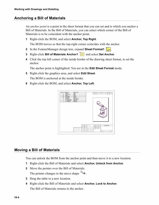
Working with Drawings and Detailing
Anchoring a Bill of Materials
An anchor point is a point in the sheet format that you can set and to which you anchor a Bill of Materials. In the Bill of Materials, you can select which corner of the Bill of Materials is to be coincident with the anchor point.1 Right-click the BOM, and select Anchor, Top Right.
The BOM moves so that the top-right corner coincides with the anchor.2 In the FeatureManager design tree, expand Sheet Format1 .3 Right-click Bill of Materials Anchor1 and select Set Anchor.4 Click the top left corner of the inside border of the drawing sheet format, to set the
anchor. The anchor point is highlighted. You are in the Edit Sheet Format mode.
5 Right-click the graphics area, and select Edit Sheet.The BOM is anchored at the inside border.
6 Right-click the BOM, and select Anchor, Top Left.
Moving a Bill of Materials
You can unlock the BOM from the anchor point and then move it to a new location.1 Right-click the Bill of Materials and select Anchor, Unlock from Anchor.2 Move the pointer over the Bill of Materials.
The pointer changes to the move shape .3 Drag the table to a new location.4 Right-click the Bill of Materials and select Anchor, Lock to Anchor.
The Bill of Materials returns to the anchor.
16-4

Chapter 16 Bill of Materials
Editing a Bill of Materials
Next, enter descriptions for the items.1 Right-click the Bill of Materials and select Edit Bill of Materials, or double-click the
Bill of Materials. While the Bill of Materials is active, it is displayed with shaded borders and row and column headers. Excel toolbars replace the SolidWorks toolbars.
2 To see all the rows, drag the lower-right corner of the border and resize the table. You can also resize the columns and rows as in any Excel worksheet.
3 Click in cell D2, type a description, then press Enter. 4 Continue to add descriptions. 5 You can also resize the text, change the font, and so on.
a) Select the text.b) Set the font size to 16 points.c) Click Format, Row, AutoFit and Format, Column, AutoFit Selection to adjust
the column and row sizes.6 Click outside the Bill of Materials to close it.
SolidWorks Educational Edition Getting Started 16-5

Working with Drawings and Detailing
Inserting Balloons
Balloon callouts label the parts in an assembly drawing and relate them to item numbers on the Bill of Materials.1 Click Balloon on the Annotations toolbar, or click Insert, Annotations, Balloon.
The Balloon PropertyManager appears.2 Click a component in the drawing view.
A balloon attaches to the component. The numbers correspond to the item number (upper) and quantity (lower) in the Bill of Materials.
3 Continue to click components to add balloons.4 Click OK .
To move the balloon or leader arrow, select and drag the balloon, or drag the leader by the handle.
To edit properties of the balloons, select a balloon or multiple balloons and change properties in the PropertyManager.
Saving a Bill of Materials
You can save the Bill of Materials as an Excel file for use with other applications.1 Select the Bill of Materials.2 Click File, Save As.
The Save Bill of Materials Table dialog box is displayed. Notice that the Save as type is set to Excel Files (*.xls) by default.
3 Type Ujoint_BOM in File name box and click Save. The extension .xls is added to the filename, and the file is saved to the current directory. If you wish, you can navigate to a different directory, then save the file.
For more information about adding a Bill of Materials, see the SolidWorks Online User’s Guide.
NOTE: The Excel file is not linked to the Bill of Materials in the drawing. If assembly components change, the Bill of Materials automatically updates, but the Excel file does not.
16-6

17
More about Drawings and Detailing
You can do more with drawings than what is shown in the examples in this guide. The following pages highlight some additional SolidWorks functionality in drawings and detailing. For more information, see the SolidWorks Online User’s Guide.
This chapter briefly describes SolidWorks functionality in the following areas:
� Drawings Options
� Templates and Drawing Sheet Formats
� Drawing Views
� Visio for Schematics
� Show/Hide Components
� 2D Sketching in Drawings
� Layers
� RapidDraft Drawings
� Detailing Options
� Dimensions
� Annotations
SolidWorks Educational Edition Getting Started 17-1

Working with Drawings and Detailing
Drawings
In drawings, you have options, formats, and views to consider.
Options for DrawingsThe Options dialog box on the Tools menu contains options for controlling various aspects of drawings. In addition to the default sheet scale and detail view scaling, you can specify the type of projection, detail item snapping, default edge display, and many types of automatic placement, display, and updates.
Drawing Templates and Drawing Sheet FormatsWhen opening a new drawing, you can choose from standard templates, custom templates, or a blank template. You can add customized templates for drawings to the SolidWorks system, and you can add tabs to the New SolidWorks Document dialog box.
When adding a sheet to a drawing, you select a sheet size and format. You can customize a sheet format (to match your company’s standard, for example), including text content and font, Bill of Materials anchor point, and bitmaps of your company logo. Then you can save the sheet format for future use.
You can modify the current drawing sheet, including such properties as sheet name, paper size, sheet scale, sheet format, type of projection, and the next view label. Sheet properties such as name, size, number, and scale have system-defined names that you can link to note text in the sheet format.
Drawing ViewsThe chapters on drawings in this guide introduced the Standard 3 View, Named View, Section View, and Detail View. Other possible views include the following:
• Projection View - a projection of an orthogonal view
• Auxiliary View - a projection unfolded normal to a reference edge in an existing view. You can select an edge, a silhouette edge, an axis, or a sketched line as the reference edge.
Projection view
Auxiliary view
17-2

More about Drawings and Detailing
• Broken View - an interruption of a long part that has a uniform cross-section
• Aligned Section View - a section view aligned to a sketched section line that is two contiguous lines at an angle to each other
• Section View of an Assembly - similar to a section view of a part, but with the option of excluding components from being sectioned
• Section View of a Section - a new section is calculated from the original solid model, and the view updates if the model changes.
Broken view
Aligned section view
Section view of an assembly
Section views of a section
SolidWorks Educational Edition Getting Started 17-3

Working with Drawings and Detailing
• Crop View - the view inside a closed profile such as a circle. You can crop any view except a Detail View.
• Relative View - an orthographic view defined by two orthogonal faces or planes in the model
• Alternate Position View - one drawing view (in phantom lines) superimposed precisely on another, often to show range of motion of an assembly.
• Detail View - The profile for a Detail View can be any closed sketch. You can choose to display either the profile or its circle in the parent view. If you select Circle, you can choose a style (Per Standard, Broken Circle, With Leader, No Leader, or Connected) for the detail circle label.
Crop view
Relative to model view
Alternate position view
Detail profile Detail circle Label with leader Detail view
17-4

More about Drawings and Detailing
Other aspects of drawing views that you can control include:• Editing View Properties, including scale, orientation, configuration, exploded state,
and type of dimensions (projected or isometric).• Turning off the automatic view update mode option so that performance is faster,
then manually updating individual views, or all views at once, as necessary.• Breaking the alignment of views that are automatically aligned. You can also align
one drawing view with another.• Rotating a drawing view around an edge or around its center point. You can copy
and paste views, hide or show a view, and change the display mode of a view.• Creating Detail, Auxiliary, and Projected views of exploded views.
Visio for SchematicsMicrosoft Visio® Technical Edition is tightly tied into SolidWorks so that you can insert electrical circuit diagrams, piping and pneumatic diagrams, and schematics into your SolidWorks drawings. You must have Visio on your system.
Show/Hide
You can show or hide views, components, and hidden edges in components.
• When you hide or show a view that has related views (Auxiliary, Detail, and so on), you are given the option of hiding or showing those related views also.
• In addition to hiding or showing components individually, you can hide as many components as you wish on the Hide/Show Components tab in the Drawing View Properties box. Hide Behind Plane is a quick method of hiding a number of components. The hidden components are listed on the Hide/Show Components tab in the Drawing View Properties dialog box.
• Show Hidden Edges is available for individual components from the shortcut menu when the view is in Hidden Lines Removed mode. Any number of components can be specified on the Show Hidden Edges tab in the Drawing View Properties dialog box.
Visio schematic in SolidWorks drawing
Complete assembly
Hide Component
Hide Behind Plane
SolidWorks Educational Edition Getting Started 17-5

Working with Drawings and Detailing
2D Sketching in DrawingsSketch tools and sketch relations work the same way in a drawing document as they do in a part or assembly document.
Layers Layers in drawings assign line color, thickness, and style for entities in the layers. You can hide or show individual layers. New entities are automatically added to the active layer.
You can add dimensions, annotations, and sketch entities to layers. You can add components to layers, in both part and assembly drawings. Many dialog boxes (Component Display Properties, Note Properties, Geometric Tolerance Properties, and so on) include a Layer list for selecting a named layer for the entity.
Layer information is included when importing or exporting files in .dxf or .dwg format.
RapidDraft DrawingsRapidDraft™ drawings have a format designed so you can open and work in drawing files without the model files being loaded into memory.
• When you open a new drawing document, a Create RapidDraft Drawing check box appears in the New SolidWorks Document dialog box.
• When you open an existing drawing that is not a RapidDraft drawing, a Convert to RapidDraft check box appears in the Open dialog box.
• Once a drawing is converted to RapidDraft format, it cannot be converted back.
When you convert a drawing to RapidDraft, the drawing and model are both loaded into memory. When the conversion is complete, save the drawing. Close the drawing, which also closes the model, then open the drawing again. The drawing is in RapidDraft mode.
• View borders in RapidDraft drawings are blue.• If a part or assembly is needed for an operation in a RapidDraft drawing, you are
prompted to load the model file. You can also load the model manually by right-clicking a view and selecting Load Model.
• Some changes, such as changes to a section line or detail profile, require a view update. When a drawing view requires an update, the view is displayed with a crosshatch pattern.
You can send RapidDraft drawings to other SolidWorks users without sending the model files. Other advantages include the following:
• Some engineers can work on the model while others add details and annotations to the drawing. When the drawing and model are synchronized, all the details and dimensions added to the drawing update to any geometric or topological changes in the model.
17-6
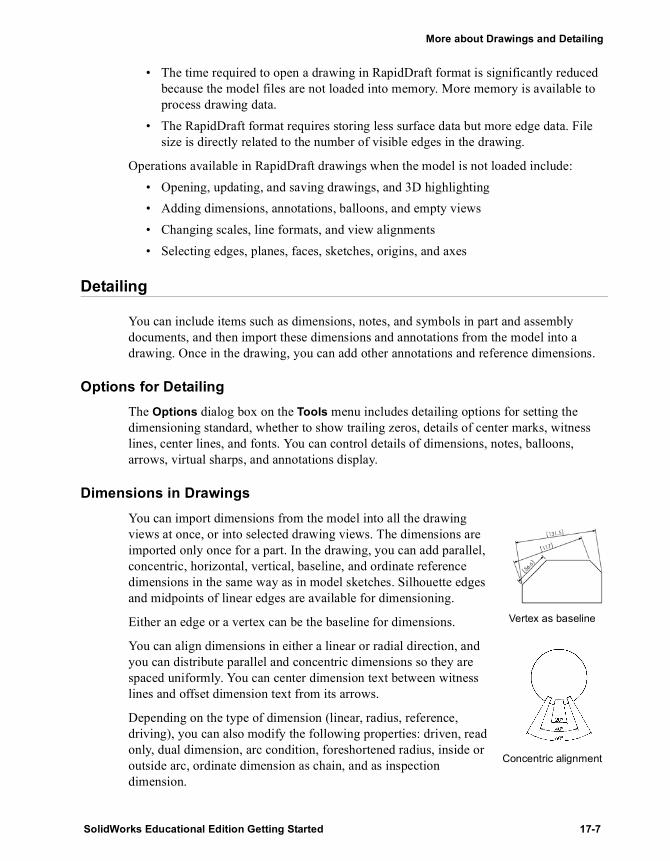
More about Drawings and Detailing
• The time required to open a drawing in RapidDraft format is significantly reduced because the model files are not loaded into memory. More memory is available to process drawing data.
• The RapidDraft format requires storing less surface data but more edge data. File size is directly related to the number of visible edges in the drawing.
Operations available in RapidDraft drawings when the model is not loaded include:• Opening, updating, and saving drawings, and 3D highlighting• Adding dimensions, annotations, balloons, and empty views• Changing scales, line formats, and view alignments• Selecting edges, planes, faces, sketches, origins, and axes
Detailing
You can include items such as dimensions, notes, and symbols in part and assembly documents, and then import these dimensions and annotations from the model into a drawing. Once in the drawing, you can add other annotations and reference dimensions.
Options for DetailingThe Options dialog box on the Tools menu includes detailing options for setting the dimensioning standard, whether to show trailing zeros, details of center marks, witness lines, center lines, and fonts. You can control details of dimensions, notes, balloons, arrows, virtual sharps, and annotations display.
Dimensions in DrawingsYou can import dimensions from the model into all the drawing views at once, or into selected drawing views. The dimensions are imported only once for a part. In the drawing, you can add parallel, concentric, horizontal, vertical, baseline, and ordinate reference dimensions in the same way as in model sketches. Silhouette edges and midpoints of linear edges are available for dimensioning.
Either an edge or a vertex can be the baseline for dimensions.
You can align dimensions in either a linear or radial direction, and you can distribute parallel and concentric dimensions so they are spaced uniformly. You can center dimension text between witness lines and offset dimension text from its arrows.
Depending on the type of dimension (linear, radius, reference, driving), you can also modify the following properties: driven, read only, dual dimension, arc condition, foreshortened radius, inside or outside arc, ordinate dimension as chain, and as inspection dimension.
Vertex as baseline
Concentric alignment
SolidWorks Educational Edition Getting Started 17-7

Working with Drawings and Detailing
Some of the dimension properties you can modify are: value, name, arrow style and placement, font, precision, witness lines, tolerance, units, and leader style. Many dimension properties are available in the PropertyManager.
Many display options are available on the dimension shortcut menu. Depending on the type of dimension selected, the Display Options menu includes items for slanting witness lines, centering or offsetting text, showing parentheses, showing as an inspection dimension, jogging or re-jogging ordinate, aligning ordinate, and adding to ordinate dimensions.
AnnotationsYou can add many types of annotations to drawings. Functionality includes:
• Multiple annotations and multiple leaders• Alignment tools, snap to grid, and inferencing for alignment• Double-click to edit in place• Link notes to document and custom properties and embed hyperlinks in notes• Hide/Show dimensions and cosmetic threads• Part number, quantity, or custom text in balloons and stacked balloons
In addition to the surface finish symbol, geometric tolerancing symbols, notes, Bill of Materials, and balloons discussed in the “Advanced Drawings and Detailing” and “Bill of Materials” chapters, you can insert the following types of annotations into drawings:
• Center Mark - to silhouette edges as well as circles and arcs• Hole Callout - dimensions update if the model changes• Datum Target - with targets as points, circles, or rectangles• Area Hatch - on faces or in closed profiles• Weld Symbol - including secondary weld fillets• Cosmetic Thread - including conical threads and thread callouts• Stacked Balloon - with one leader for the set• Block - create custom blocks with text, sketch items, and area hatch
Leader options
17-8
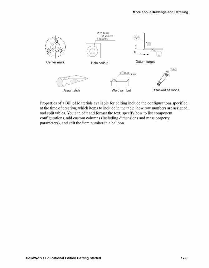
More about Drawings and Detailing
Properties of a Bill of Materials available for editing include the configurations specified at the time of creation, which items to include in the table, how row numbers are assigned, and split tables. You can edit and format the text, specify how to list component configurations, add custom columns (including dimensions and mass property parameters), and edit the item number in a balloon.
Center mark Hole callout Datum target
Area hatch Weld symbol Stacked balloons
SolidWorks Educational Edition Getting Started 17-9

Special Topics
Sheet Metal Part
Mold Design
3D Sketching
Importing Files / Using FeatureWorks Software
Learning to Use PhotoWorks
SolidWorks Animator
More about SolidWorks Functionality and Additional Products
SolidWorks Educational Edition Getting Started

18 Sheet Metal Part
In this chapter, you create the sheet metal part shown here. This chapter demonstrates:
� Creating a base flange
� Adding a miter flange
� Mirroring the part and creating new bends
� Adding and bending a tab
� Folding and unfolding a single bend as well as the entire part
� Adding a cut across a bend
� Creating a sheet metal drawing
For more information about SolidWorks sheet metal functions, see the SolidWorks Online User’s Guide.
SolidWorks Educational Edition Getting Started 18-1

Special Topics
Creating the Base Flange
When developing a sheet metal part, you generally design the part in the folded state. This allows you to capture the design intent and the dimensions of the finished part.
To create a sheet metal part of uniform thickness, sketch an open profile and use the base flange feature to create the thin feature and the bends.1 Open a new part from the Tutorial tab and open a sketch on the Front plane.2 Placing the lower left corner of the sketch on the origin,
sketch and dimension the profile as shown. Add an Equal relation between the two vertical lines.
3 Click Base-Flange/Tab on the Sheet Metal toolbar, or click Insert, Sheet Metal, Base Flange.
The Base Flange PropertyManager appears.4 Under Direction 1, leave End Condition as Blind and set the
Depth to 75mm.5 Under Sheet Metal Parameters, do the following:
a) Set Thickness to 3mm.b) Set Bend Radius to 1mm. This is the default.
6 Click OK .The sketch is extruded and the bends are automatically added.
Examining the FeatureManager Design Tree
A base flange feature creates three new features in the FeatureManager design tree. The following are the three new features:
Sheet-Metal1. The Sheet-Metal feature contains the default bend parameters. To edit the default bend radius, bend allowance, or default relief type, right-click the Sheet-Metal feature and select Edit Definition.
Base-Flange. The Base-Flange feature is the first solid feature of the sheet metal part.
Flat-Pattern1. The Flat-Pattern feature flattens the sheet metal part. Notice it is suppressed by default as the part is in its bent state. Unsuppress the feature to flatten the sheet metal part.
When the Flat-Pattern feature is suppressed, all new features that you add to the part are automatically inserted above the Flat-Pattern feature in the FeatureManager design tree. When the Flat-Pattern feature is unsuppressed, new features go below it in the FeatureManager design tree and are not shown in the folded part.
NOTE: If the Sheet Metal toolbar is not visible, click View, Toolbars, Sheet Metal.
18-2

Chapter 18 Sheet Metal Part
Adding a Miter Flange
You can add flanges to your sheet metal part with corners that are automatically mitered.1 Select the inside vertical edge approximately as
shown and click Sketch to open a new sketch.A sketch plane is created normal to the selected edge with its origin at the closest endpoint of the edge.
2 Sketch a horizontal line starting from the inside vertex shown extending towards the middle of the part. Dimension the line to 8mm.
3 Click Miter Flange on the Sheet Metal toolbar, or click Insert, Sheet Metal, Miter Flange.The Miter Flange PropertyManager appears.
4 Click Propagate that appears on the selected edge.The five tangent edges appear in the Along Edges box under Miter Parameters.Also, a preview of the miter flange appears on the model.
5 Click OK .The flange is added to the selected edges. Notice the bend reliefs are automatically added to allow the miter flanges to fold and unfold.
6 Save the part as Cover.sldprt.
Mirroring the Sheet Metal Bends
When you mirror a sheet metal part, many of the bends are mirrored as well. The only bends that are not mirrored are those that are normal to and coincident to the mirror plane; those bends are extended.1 Click Hidden in Gray .2 Click Insert, Pattern/Mirror, Mirror All.
The Mirror All PropertyManager appears.3 Under Mirror Plane1, select one of the back planar faces as
the mirror plane. Use Select Other from the shortcut menu if necessary.
Edge
Vertex
SolidWorks Educational Edition Getting Started 18-3

Special Topics
4 Click OK and click Shaded .The entire part is mirrored as well as the sheet metal bends from the miter flange.
5 Expand the Mirror1 feature in the FeatureManager design tree and notice that there are new bends to include the mirrored geometry.
Adding a Tab
1 Open a sketch on the vertical face shown.2 Sketch a rectangle above the sheet metal body with
its lower edge coincident to the edge shown. Dimension the rectangle to 50mm high and 100mm wide.
3 Add a coincident relation between the midpoint of one of the horizontal lines of the rectangle and the Front plane.
The sketch should look like this when you are done.
4 Click Base-Flange/Tab .The tab is added to the part. You do not need to specify a depth because the SolidWorks software links the thickness of the tab to the thickness of the base flange.
TIP: To select the midpoint of a line or edge, right-click the line or edge and click Select Midpoint.
FaceEdge
18-4

Chapter 18 Sheet Metal Part
Bending the Tab
Once you add a tab, you must specify how to bend it.1 Select the same vertical face from the previous section and open a sketch.2 Sketch a horizontal line of any length. Dimension it to 30mm
below the top of the tab as shown.The bend line for a Sketched Bend does not have to be the exact length of the faces you are bending.
3 Click Sketched Bend on the Sheet Metal toolbar, or click Insert, Sheet Metal, Sketched Bend.The Sketched Bend PropertyManager appears.
4 Under Bend Parameters, do the following:• Select the vertical face below the bend line as the Fixed
face.• Set Bend position to Bend Outside .• Make sure Bend Angle is set to 90° and the Use
default radius check box is selected.5 Click OK .6 Save the part.
Adding a Cut Across a Bend
To cut across a bend, you start by unfolding only the bend that you want to cut across.1 Click Unfold on the Sheet Metal toolbar, or
click Insert, Sheet Metal, Unfold.The Unfold PropertyManager appears.
2 Select the face shown as the Fixed face and the bend shown as the Bends to unfold.Notice that you can only select bends when the Bends to unfold box is active. Bend
Face
SolidWorks Educational Edition Getting Started 18-5

Special Topics
3 Click OK .The selected bend only is unfolded.
Next, you create a sketch and cut through the bend.1 Open a sketch on the face shown, and sketch and
dimension a rectangle as shown. The 60mm dimension goes from the left edge of the rectangle to the origin.
2 Click Extruded Cut or Insert, Cut, Extrude. Select Through All as End Condition, then click OK .
The cut goes through the bend region.
Now that you made your cut, fold the bend back to its bent state.1 Click Fold on the Sheet Metal toolbar, or click
Insert, Sheet Metal, Fold.The Fold PropertyManager appears.
2 Select the bottom face of the sheet metal part as the Fixed face.
3 Click Collect All Bends to collect all the unfolded bends.The unfolded bend appears in the Bends to fold box.
4 Click OK .The part returns to its fully bent state with the cut across the bends.
18-6
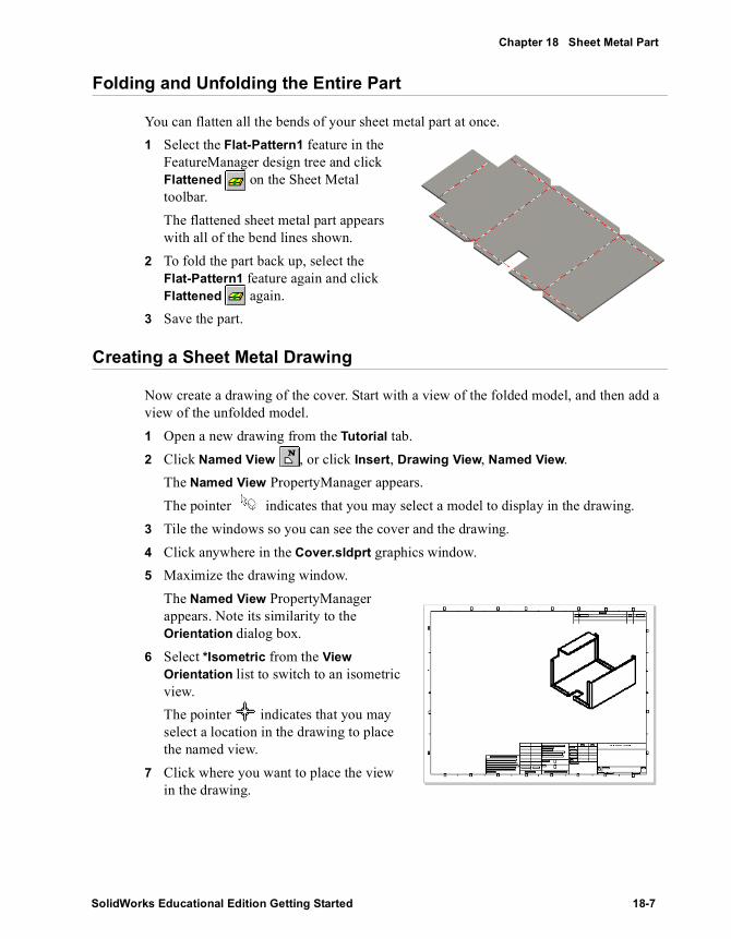
Chapter 18 Sheet Metal Part
Folding and Unfolding the Entire Part
You can flatten all the bends of your sheet metal part at once.1 Select the Flat-Pattern1 feature in the
FeatureManager design tree and click Flattened on the Sheet Metal toolbar.The flattened sheet metal part appears with all of the bend lines shown.
2 To fold the part back up, select the Flat-Pattern1 feature again and click Flattened again.
3 Save the part.
Creating a Sheet Metal Drawing
Now create a drawing of the cover. Start with a view of the folded model, and then add a view of the unfolded model.1 Open a new drawing from the Tutorial tab.2 Click Named View , or click Insert, Drawing View, Named View.
The Named View PropertyManager appears.The pointer indicates that you may select a model to display in the drawing.
3 Tile the windows so you can see the cover and the drawing.
4 Click anywhere in the Cover.sldprt graphics window.5 Maximize the drawing window.
The Named View PropertyManager appears. Note its similarity to the Orientation dialog box.
6 Select *Isometric from the View Orientation list to switch to an isometric view.The pointer indicates that you may select a location in the drawing to place the named view.
7 Click where you want to place the view in the drawing.
SolidWorks Educational Edition Getting Started 18-7

Special Topics
Next, add the view of the unfolded model. A flat pattern view is automatically added when you create a sheet metal part.1 Click Named View again.2 Select the isometric view as the model you want to use.3 In the Named View PropertyManager, do the following:
a) Select Flat pattern from the View Orientation list.b) Select the Custom Scale check box and set the scale to 1:3.
4 Click where you want to place the view in the drawing.
5 Save the drawing as Cover.slddrw.
18-8

19 Mold Design
In this chapter, you create a design part, then you develop a mold from which the part can be formed. This chapter discusses the following topics:
� Linking dimension values
� Creating an interim assembly from a design part and a mold base part
� Editing in context by inserting a cavity
� Deriving component parts
� Understanding external references
SolidWorks Educational Edition Getting Started 19-1
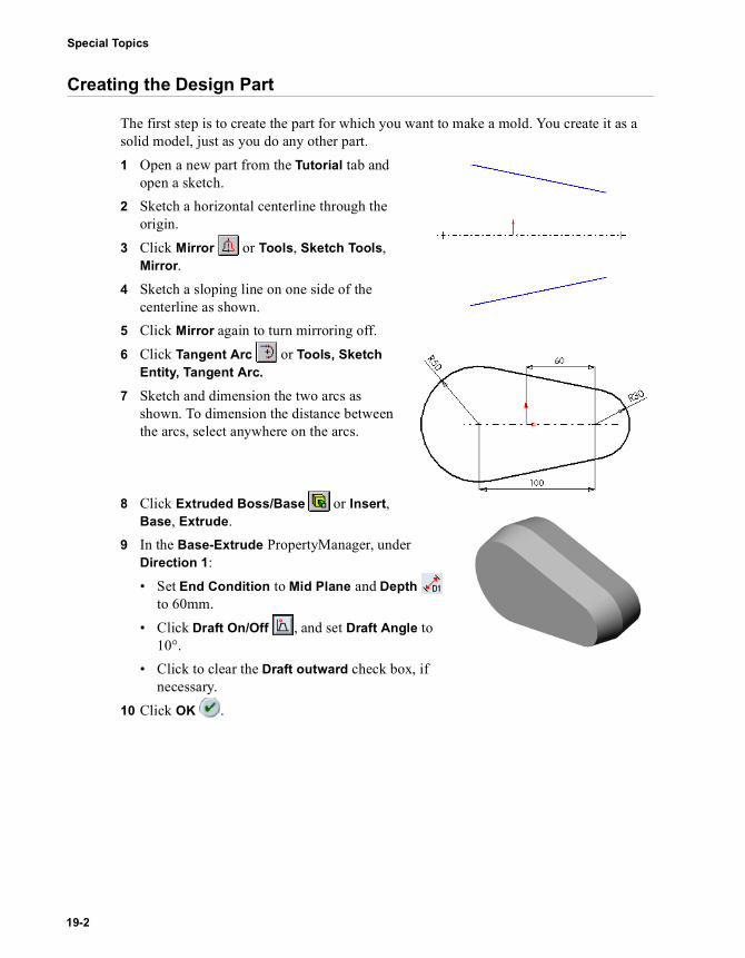
Special Topics
Creating the Design Part
The first step is to create the part for which you want to make a mold. You create it as a solid model, just as you do any other part.1 Open a new part from the Tutorial tab and
open a sketch.2 Sketch a horizontal centerline through the
origin.3 Click Mirror or Tools, Sketch Tools,
Mirror. 4 Sketch a sloping line on one side of the
centerline as shown.5 Click Mirror again to turn mirroring off.6 Click Tangent Arc or Tools, Sketch
Entity, Tangent Arc.
7 Sketch and dimension the two arcs as shown. To dimension the distance between the arcs, select anywhere on the arcs.
8 Click Extruded Boss/Base or Insert, Base, Extrude.
9 In the Base-Extrude PropertyManager, under Direction 1: • Set End Condition to Mid Plane and Depth
to 60mm.• Click Draft On/Off , and set Draft Angle to
10°.• Click to clear the Draft outward check box, if
necessary.10 Click OK .
19-2
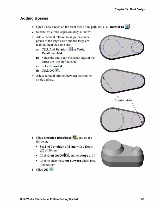
Chapter 19 Mold Design
Adding Bosses
1 Open a new sketch on the front face of the part, and click Normal To .2 Sketch two circles approximately as shown.3 Add a coradial relation to align the center
points of the large circle and the large arc, making them the same size:a) Click Add Relation or Tools,
Relations, Add.b) Select the circle and the inside edge of the
larger arc (the drafted edge).c) Select Coradial.d) Click OK .
4 Add a coradial relation between the smaller circle and arc.
5 Click Extruded Boss/Base , and do the following:• Set End Condition of Blind with a Depth
of 20mm.• Click Draft On/Off , and set Angle to 30°.• Click to clear the Draft outward check box,
if necessary.6 Click OK .
Coradial relation
SolidWorks Educational Edition Getting Started 19-3

Special Topics
Linking Dimension Values
You can make the draft angles of the boss and the base equal by linking the dimension values. Then, if you change the value of either draft angle, the other draft angle updates accordingly.1 In the FeatureManager design tree, right-click the
Annotations folder , and select Show Feature Dimensions.
2 Right-click the dimension of the draft angle of the base (10°), and select Link Values.
3 Type draft in the Name box, then click OK.4 Right-click the dimension of the draft angle of the boss
(30°), and select Link Values.
5 Click the arrow beside the Name box, select draft from the list, and click OK.Each time you create a new Name variable, it is added to this list.
6 Click Tools, Options. On the System Options tab, click General.
7 Select the Show dimension names check box, then click OK. Notice that the draft angles have the same name.
8 Click Rebuild or Edit, Rebuild. The part rebuilds with the boss extrusion at the same draft angle as the base.
9 Double-click the draft angle of either the base or boss, and change it to 5°.10 Click Rebuild . The draft angle
changes on both the base and the boss.11 To turn off the visibility of the
dimensions, right-click the Annotations folder , and deselect Show Feature Dimensions.
12 Save this part as Widget.sldprt.
19-4

Chapter 19 Mold Design
Rounding the Edges
1 Click Fillet or Insert, Features, Fillet/Round.
2 Select the two faces and three edges shown.3 Set the Radius to 5mm.4 Select the Tangent propagation check box.
5 Click OK .6 Save the part.
Creating the Mold Base
The next step is to create the mold base part, a solid block large enough to accommodate the design part (the part to be molded).1 Open a new part from the Tutorial tab and open a sketch.2 Sketch a rectangle starting at the origin and dimension it to 300mm x 200mm.3 Click Extruded Boss/Base or Insert, Base, Extrude. Extrude the rectangle with
End Condition as Blind and Depth of 200mm.4 Save the part as Box.sldprt.
Select these edges
Select these faces
SolidWorks Educational Edition Getting Started 19-5

Special Topics
Creating an Interim Assembly
This section describes how to create an interim assembly, bringing together the design part and the mold base. 1 Open a new assembly from the Tutorial tab and click View, Origins to show the
origins.2 Tile the windows. (Click Window, Tile Horizontally or Tile Vertically.)
There should be three windows open: Widget.sldprt, Box.sldprt, and Assem1. (Close any other windows.)
3 In the Box.sldprt window, click on the part name Box in the FeatureManager design tree, drag it into the Assem1 window, and drop it on the origin in the graphics area. Watch for the pointer. The planes of the box are aligned to the planes of the assembly, and the component is fixed in place.
4 Drag the widget from the graphics area of the Widget.sldprt window, and drop it in the assembly window beside the box in the graphics area.
5 Maximize the assembly window, and change the view orientation to Isometric .
6 In the FeatureManager design tree, click the beside each component to expand the view of the features.
Centering the Design Part in the Mold Base
Now you need to position the design part to center it within the mold base. You can place the widget roughly where you want it by dragging. Position the part more precisely by using distance mates between the planes of the components.
To see the widget inside the box, use Hidden In Gray or Wireframe display mode. Or, you can make the box transparent to see the widget inside, even in Shaded mode.1 Right-click the Box component in the FeatureManager design tree, and select
Component Properties. Click Color, then click Advanced. 2 In the Advanced Properties dialog box, drag the slider for Transparency to the right,
a little less than halfway. Click OK to close each of the dialog boxes.
19-6

Chapter 19 Mold Design
3 Click Move Component , and click the widget component in the graphics area. Drag the widget into the box. Notice how you can see through the box. Change the view orientation, and continue to move the widget until it is roughly in the center of the box.
4 Click Mate or Insert, Mate. The Mate PropertyManager appears.
5 Click the FeatureManager design tree tab to access the flyout FeatureManager design tree.
6 Click the Front plane of the Box and the Front plane of the Widget. Click Distance , specify 100mm, and click Preview.
7 Click Rotate View , and rotate the assembly to check the position of the widget. If necessary, click to clear the Flip dimension check box, and click Preview again.
8 Click the pushpin in the Mate PropertyManager to keep it in place for the next few steps.
9 Click OK .10 Add another distance mate, this time between the Top plane of the Box and the Top
plane of the Widget. Specify a distance of 100mm, click Preview, and click to clear the Flip dimension check box if necessary.
11 Repeat for the Right plane of the components, with a distance of 150mm.The widget should be centered in the box.
12 Close the Mate PropertyManager.13 Save the assembly as Mold.sldasm.
Creating the Cavity
In this section, you edit the mold base component Box in the context of the assembly. You change the box from a solid block to a block with a cavity in the middle, shaped like the design component Widget.1 Click Hidden in Gray .2 Click the Box component in the FeatureManager design tree or the graphics area, and
click Edit Part on the Assembly toolbar.The Box component changes to pink in the graphics area and in the FeatureManager design tree. The status bar in the lower-right corner displays “Editing Part.”
NOTE: It is important to be aware that you are editing the part, not the assembly, because the changes you make are reflected in the original part document, Box.sldprt.
SolidWorks Educational Edition Getting Started 19-7

Special Topics
3 Click Cavity on the Mold Tools toolbar, or click Insert, Features, Cavity. The Cavity dialog box appears.
4 Select Widget in the FeatureManager design tree. The name of the part appears in the Design component box.
5 Set Type to Component Centroids, Scaling factor in % to 2, and make sure the Uniform check box is selected.These settings control how the cavity is enlarged to compensate for material shrinkage.
6 Click OK to create a cavity in the shape of the Widget part.7 Return to assembly editing mode by clicking Edit Part .8 Save the assembly.
Listing External References
Examine the FeatureManager design tree. The (f)Box<1> -> component contains a Cavity1 -> feature. The -> arrow indicates an external reference. This occurs when you reference one part (or feature) to create a feature in another part. The new feature is dependent on the referenced feature of the other part.
A cavity has an external reference to the design part on which it is based. Therefore, if you modify Widget, the Cavity1 feature of Box updates to reflect that change. Notice the Update Cavity1 in Box feature at the bottom of the design tree.
To list the external references, right-click the part or feature with the arrow, and select List External Refs.
NOTE: External references update automatically only if all of the documents involved are open when a change is made. Otherwise, the references are considered to be out-of-context. To update out-of-context references, you must open and rebuild the document where the reference was created (in this example, the mold assembly).
External References
19-8

Chapter 19 Mold Design
Cutting the Mold
The last step is to cut the box in half to make the pieces of the mold. You derive the parts of the mold from the edited Box component.1 Select the Box component, either in the graphics area or the FeatureManager design
tree, and click File, Derive Component Part.A part window appears for the derived part. A derived part always has another part as its first feature. The first feature has an arrow -> after the name, because it has an external reference to the part from which you derived it. You can list the external references as described in the previous section.
2 Click Isometric , then click either Hidden in Gray or Wireframe to see the cavity inside the box.
3 Select the narrow face of the box closest to you, and open a new sketch.
4 Select the edge of the cavity closest to the end of the box. This edge is on the plane where you want to separate the mold.
5 Click Convert Entities or Tools, Sketch Tools, Convert Entities to project the edge onto the sketch plane.
6 Click the line and drag each endpoint so that the line is wider than the box.
7 Click Extruded Cut or Insert, Cut, Extrude. In the Cut-Extrude PropertyManager:• Make sure End Condition is set to Through
All.• Leave the Flip side to cut check box cleared.Notice the direction of the arrow in the graphics area. It points to the side where the material will be removed.
Select this edge
Select this face
SolidWorks Educational Edition Getting Started 19-9

Special Topics
8 Click OK .
9 Click Shaded , and rotate the part to see the cavity.10 Save this half of the mold as Top_mold.sldprt.11 To create the other half of the mold, return to the Mold
assembly window and repeat steps 1 through 7. Reverse the direction of the cut by selecting the Flip side to cut check box in the Cut-Extrude PropertyManager.
12 Save this half of the mold as Bottom_mold.sldprt.
19-10

20 3D Sketching
Using SolidWorks, you can create 3D sketches. You can use a 3D sketch as a sweep path, as a guide curve for a loft or sweep, a centerline for a loft, or as one of the key entities in a piping system. (For more information about the SolidWorks Piping add-in, see Building Piping Systems on page 24-9.)
This chapter introduces you to 3D sketching and describes the following concepts:
� Sketching relative to coordinate systems
� Using the space handle
� Dimensioning in 3D space
� Relations available in 3D sketching
SolidWorks Educational Edition Getting Started 20-1
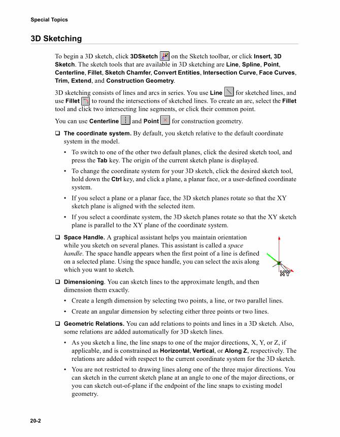
Special Topics
3D Sketching
To begin a 3D sketch, click 3DSketch on the Sketch toolbar, or click Insert, 3D Sketch. The sketch tools that are available in 3D sketching are Line, Spline, Point, Centerline, Fillet, Sketch Chamfer, Convert Entities, Intersection Curve, Face Curves, Trim, Extend, and Construction Geometry.
3D sketching consists of lines and arcs in series. You use Line for sketched lines, and use Fillet to round the intersections of sketched lines. To create an arc, select the Fillet tool and click two intersecting line segments, or click their common point.
You can use Centerline and Point for construction geometry.
� The coordinate system. By default, you sketch relative to the default coordinate system in the model. • To switch to one of the other two default planes, click the desired sketch tool, and
press the Tab key. The origin of the current sketch plane is displayed.• To change the coordinate system for your 3D sketch, click the desired sketch tool,
hold down the Ctrl key, and click a plane, a planar face, or a user-defined coordinate system.
• If you select a plane or a planar face, the 3D sketch planes rotate so that the XY sketch plane is aligned with the selected item.
• If you select a coordinate system, the 3D sketch planes rotate so that the XY sketch plane is parallel to the XY plane of the coordinate system.
� Space Handle. A graphical assistant helps you maintain orientation while you sketch on several planes. This assistant is called a space handle. The space handle appears when the first point of a line is defined on a selected plane. Using the space handle, you can select the axis along which you want to sketch.
� Dimensioning. You can sketch lines to the approximate length, and then dimension them exactly.• Create a length dimension by selecting two points, a line, or two parallel lines.• Create an angular dimension by selecting either three points or two lines.
� Geometric Relations. You can add relations to points and lines in a 3D sketch. Also, some relations are added automatically for 3D sketch lines. • As you sketch a line, the line snaps to one of the major directions, X, Y, or Z, if
applicable, and is constrained as Horizontal, Vertical, or Along Z, respectively. The relations are added with respect to the current coordinate system for the 3D sketch.
• You are not restricted to drawing lines along one of the three major directions. You can sketch in the current sketch plane at an angle to one of the major directions, or you can sketch out-of-plane if the endpoint of the line snaps to existing model geometry.
20-2

Chapter 20 3D Sketching
� Line snap. During the creation of a line, you can snap the line to geometry that already exists in the part, such as model surfaces or vertices, and sketch points. • Snap is not enabled if you are sketching in one of the major coordinate directions.• If you are sketching on a plane, and the system infers a snap to a non-planar point, a
temporary 3D graphics box is displayed to indicate an off-planar snap.
� Virtual sharps. When you create an arc with the Fillet tool, the original common point of the lines is displayed as a virtual sharp. To change the display of the virtual sharp, click Tools, Options, Document Settings. Under Detailing, select Virtual Sharps. Choose one of the styles that are depicted.• You can add dimensions and relations to virtual sharps in a 3D sketch. • If you delete an arc, the lines extend to meet at the virtual sharp.• If you delete a line used to create a fillet, any arc it was joined with remains. The
virtual sharp becomes a sketch point.
Using a 3D Sketch to Create an Oven Rack Frame
The outer frame of a wire oven rack is built by sweeping a circle along a 3D sketch.
After you complete half of the rack, then you can take advantage of the part’s symmetry and use the Mirror All function to finish the model.
To create the 3D sketch of the outer frame:
1 Open a new part on the Tutorial tab, and click Isometric to change the view orientation.
2 Click 3D Sketch or click Insert, 3D Sketch, to open a new sketch.
TIP: It is easier to create a 3D sketch in an isometric orientation because theX, Y, and Z directions are visible.
Outer frame
SolidWorks Educational Edition Getting Started 20-3

Special Topics
3 Click Line and sketch a 135mm line on the XY plane from the origin along the X axis. The pointer changes to while sketching along the X axis.
4 Click Select and click the beginning endpoint of the line. Make sure that the endpoint is exactly at the point of the origin (0, 0, 0 as shown in the Parameters section of the Point PropertyManager). The point is Coincident with the origin, as shown in the Existing Relations box .
5 Click Fix in Add Relations to add a Fixed relation. Now the point is fixed, and it is fully defined, as shown in Information .
6 Click Line and continue sketching the other lines from the endpoint of the previous line. Each time you begin a new line, the origin for the current coordinate system is displayed at the beginning of the new line to help orient you.a) Sketch down the Y axis for 15mm.b) Sketch along the X axis for 15mm.c) Press Tab to change the sketch plane to the
YZ plane .d) Sketch along the Z axis for 240mm.e) Press Tab twice to change the sketch plane
back to the XY plane.f) Sketch back along the X axis for 15mm.g) Sketch up the Y axis for 15mm.h) Sketch back along the X axis for 135mm.
7 Dimension each of the lines as shown.8 Click Fillet on the Sketch Tools toolbar, or
click Tools, Sketch Tools, Fillet, and fillet each intersection with a 5mm fillet.
9 Close the sketch.10 Save the part as Rack.sldprt.
TIP: Sketch the line to an approximate length, then dimension to the exact length later.
Begin sketch line at origin.
20-4
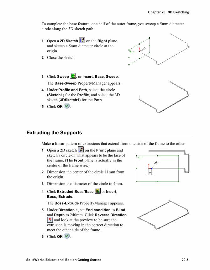
Chapter 20 3D Sketching
To complete the base feature, one half of the outer frame, you sweep a 5mm diameter circle along the 3D sketch path.
1 Open a 2D Sketch on the Right plane and sketch a 5mm diameter circle at the origin.
2 Close the sketch.
3 Click Sweep , or Insert, Base, Sweep. The Base-Sweep PropertyManager appears.
4 Under Profile and Path, select the circle (Sketch1) for the Profile, and select the 3D sketch (3DSketch1) for the Path.
5 Click OK .
Extruding the Supports
Make a linear pattern of extrusions that extend from one side of the frame to the other. 1 Open a 2D sketch on the Front plane and
sketch a circle on what appears to be the face of the frame. (The Front plane is actually in the center of the frame wire.)
2 Dimension the center of the circle 11mm from the origin.
3 Dimension the diameter of the circle to 4mm.
4 Click Extruded Boss/Base or Insert, Boss, Extrude.The Boss-Extrude PropertyManager appears.
5 Under Direction 1, set End condition to Blind, and Depth to 240mm. Click Reverse Direction
and look at the preview to be sure the extrusion is moving in the correct direction to meet the other side of the frame.
6 Click OK .
SolidWorks Educational Edition Getting Started 20-5

Special Topics
Now pattern the extrusion.1 Click View, Temporary Axes to turn on the display of all temporary axes.2 In the FeatureManager design tree, select Boss-Extrude1 and click Linear Pattern
or Insert, Pattern/Mirror, Linear Pattern.The Linear Pattern PropertyManager appears.
3 Click the temporary axis on the face of the frame where you sketched the circle.An arrow that points in the direction the pattern will take appears on the frame at the right end of the axis, and Axis <1> appears in the Pattern Direction box.
4 Under Direction 1: • Click Reverse direction if
necessary. Check the preview for the direction of the pattern.
• Set Spacing to 22mm.• Set Number of Instances to 6.
5 Click OK .The extrusion pattern is completed.
Use the Mirror All function to complete the wire rack.1 Click Insert, Pattern/Mirror, Mirror All.
The Mirror All PropertyManager appears.
2 Rotate the half-rack that you created and click on the end face of the frame. Face <1> appears in the Mirror Face
box.3 Click OK.
The rack is completed.4 Save the model.
20-6

21 Importing Files / Using FeatureWorks Software
This chapter guides you through the import of a gasket and a company logo, and demonstrates the following:
� Importing an IGES file
� Using the FeatureWorks software to recognize features on the imported solid
� Importing a DXF file
� Copying a sketch from a drawing to use for a feature in a part
� Exporting a SolidWorks part document as an STL file
SolidWorks Educational Edition Getting Started 21-1

Special Topics
Importing an IGES File
You can import surfaces from IGES files and use them to create a base feature if the surfaces form a closed volume.1 Click File, Open.
The Open dialog box appears.2 In the Files of type list, click IGES Files (*.igs, *.iges).3 Click Options to set the import options.4 Make sure Knitting and Try forming solid(s) are selected, then click OK.
When these two options are selected, the SolidWorks software attempts to knit the surfaces from an imported file into a solid model.
5 Browse to the path \installation directory\samples\tutorial, select gasket.igs, and click Open.Once the SolidWorks software finishes knitting the surfaces into a base feature, the dialog box disappears and the imported body appears in the graphics area.
6 If a message appears asking if you want to proceed with feature recognition, click No.Notice the new feature, Imported1, in the FeatureManager design tree. You cannot edit the sketches, dimensions, or features of an imported solid model.
21-2

Chapter 21 Importing Files / Using FeatureWorks Software
Recognizing Features using the FeatureWorks Software
The FeatureWorks software recognizes features on an imported solid body in a part document. Recognized features are the same as features that you create using the SolidWorks software. You can edit the definition of recognized features to change their parameters. For features that are based on sketches, you can edit the sketches of recognized features to change the geometry of the features.
1 If FeatureWorks does not appear on the SolidWorks main menu bar, click Tools, Add-Ins, select FeatureWorks, and click OK.
2 Click FeatureWorks Options on the toolbar, or click FeatureWorks, Options. Make sure the Overwrite existing part and the Basic features check boxes are selected, then click OK.Selecting the Basic features check box enables the FeatureWorks software to recognize extrusions and revolves during Automatic Feature Recognition.
3 Click Recognize Features on the toolbar, or click FeatureWorks, Recognize Features.The FeatureWorks PropertyManager appears.
4 To recognize a single feature:a) Under Recognition Mode, click Interactive.b) Under Interactive Features, set Feature Type
to Cut Extrude.c) Select the circular edge of the cut as shown.
Edge <1> appears in the Selected Entities box.d) Click Recognize.The selected edge is recognized as the sketch for a Cut-Extrude feature. The recognized feature disappears from the solid body. Any geometry not yet recognized still appears in the graphics area.
5 Under Recognition Mode, click Automatic, then click Recognize to perform Automatic Feature Recognition.FeatureWorks attempts to recognize as many features as possible from the remaining geometry.
NOTE: If you do not have the FeatureWorks software installed on your computer, please turn to Importing a DXF File on page 21-4. You can still complete the remainder of the exercise if you do not have the FeatureWorks software.
Select this edge
SolidWorks Educational Edition Getting Started 21-3
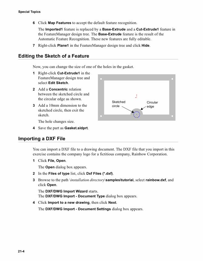
Special Topics
6 Click Map Features to accept the default feature recognition.The Imported1 feature is replaced by a Base-Extrude and a Cut-Extrude1 feature in the FeatureManager design tree. The Base-Extrude feature is the result of the Automatic Feature Recognition. These new features are fully editable.
7 Right-click Plane1 in the FeatureManager design tree and click Hide.
Editing the Sketch of a Feature
Now, you can change the size of one of the holes in the gasket.1 Right-click Cut-Extrude1 in the
FeatureManager design tree and select Edit Sketch.
2 Add a Concentric relation between the sketched circle and the circular edge as shown.
3 Add a 10mm dimension to the sketched circle, then exit the sketch.The hole changes size.
4 Save the part as Gasket.sldprt.
Importing a DXF File
You can import a DXF file to a drawing document. The DXF file that you import in this exercise contains the company logo for a fictitious company, Rainbow Corporation.1 Click File, Open.
The Open dialog box appears.2 In the Files of type list, click Dxf Files (*.dxf).3 Browse to the path \installation directory\samples\tutorial, select rainbow.dxf, and
click Open.The DXF/DWG Import Wizard starts. The DXF/DWG Import - Document Type dialog box appears.
4 Click Import to a new drawing, then click Next.The DXF/DWG Import - Document Settings dialog box appears.
Sketched circle
Circular edge
21-4

Chapter 21 Importing Files / Using FeatureWorks Software
5 Do the following:a) Select the Show preview check box.b) Select A-Landscape as the Paper size. c) Click Position, then set X and Y to 0 (zero).d) Under Document template, browse to the path \installation
directory\lang\<your_language>\tutorial\, select draw.drwdot, and click Open.6 Click Next.
The DXF/DWG Import - Drawing Layer Mapping dialog box appears.7 Click Import all data to the sheet, then click Finish.
A new drawing document is created containing the entities in the DXF file. The imported company logo consists of lines, arcs, and dimensions.
Prepare the Imported Entities for Copying
Before you copy imported DXF entities from a drawing to a sketch in a part, you must prepare the entities. The imported sketch entities are unconstrained; there are no relations between the entities. Also, the dimensions in the imported DXF file are not attached to any sketch entities.1 Click Tools, Relations, Constrain All.
The SolidWorks software adds all the apparent relations and reports the number of relations that are added.
2 Click OK in the message box.3 Click Display/Delete Relations or Tools, Relations, Display/Delete.
The Sketch Relations PropertyManager appears.4 Under Edit External References, scroll through the relations listed in the Relations
box.Notice that the SolidWorks software added many Coincident, Collinear, and Horizontal relations.
5 Click OK to close the Sketch Relations PropertyManager.6 Click Tools, Dimensions, Attach Dimensions.
Each dimension in the imported DXF file is attached to the appropriate arc.7 Click OK in the message box.8 Click Rebuild on the Standard toolbar.
SolidWorks Educational Edition Getting Started 21-5

Special Topics
Copying and Pasting the Imported Entities
You can copy entities from a drawing to a sketch of a part. The software creates a new sketch in the part once you paste the entities.1 Drag-select the entities on the drawing, including the dimensions.2 Click Copy or press Ctrl+C.3 Click Window, gasket to switch to the part.4 Select the front face of the gasket, then click
Paste or press Ctrl+V.A new sketch is created in the part containing the company logo.
5 Right-click Sketch3 and select Edit Sketch.
Notice that all of the dimensions and entities from the drawing are in the new sketch.
6 Add the 5mm and 20mm dimensions as shown to position the sketch entities.
21-6
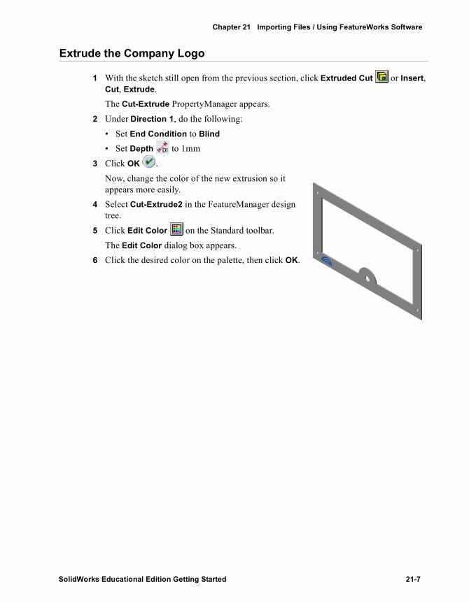
Chapter 21 Importing Files / Using FeatureWorks Software
Extrude the Company Logo
1 With the sketch still open from the previous section, click Extruded Cut or Insert, Cut, Extrude.The Cut-Extrude PropertyManager appears.
2 Under Direction 1, do the following:• Set End Condition to Blind
• Set Depth to 1mm3 Click OK .
Now, change the color of the new extrusion so it appears more easily.
4 Select Cut-Extrude2 in the FeatureManager design tree.
5 Click Edit Color on the Standard toolbar.The Edit Color dialog box appears.
6 Click the desired color on the palette, then click OK.
SolidWorks Educational Edition Getting Started 21-7

Special Topics
Exporting an STL File
You can save a SolidWorks part document as an STL file. STL format is intended for transfer to rapid prototyping machines.1 Click File, Save As.
The Save As dialog box appears.2 In the Save as type list, click STL Files (*.stl), then click Options to set the export
options.The STL Export Options dialog box appears.
3 Make sure the Quality is set to Fine and the Show STL info before file saving check box is selected, then click OK.
4 Click Save to save the file with the default name, gasket.stl.A message box appears displaying the number of Triangles, File Size, and File Format.
5 Click Yes to complete the save operation.
TIP: You can experiment with the Quality settings to determine the best settings for your own rapid prototyping machines.
21-8

22 Learning to use PhotoWorks
This chapter teaches you how to use the PhotoWorks software to create photo-realistic images of SolidWorks models. This chapter covers the following topics:
� PhotoWorks fundamentals
� Using the PhotoWorksManager
� Rendering an image with the PhotoWorks Render Wizard
� Selecting and applying PhotoWorks materials
� Previewing and editing PhotoWorks materials
� Rendering a sub-image
� Saving and viewing image files
� Creating and managing PhotoWorks material archives
� Creating and applying decals with the PhotoWorks Decal Wizard
� Designing PhotoWorks scenery
SolidWorks Educational Edition Getting Started 22-1

Special Topics
Section 1: PhotoWorks Fundamentals
Before you begin, there are a few things you need to know about the PhotoWorks software.
� PhotoWorks software creates realistic images directly from SolidWorks models. The PhotoWorks software interacts with the 3D geometry that you create with SolidWorks software. All changes to SolidWorks models are accurately represented in PhotoWorks images.
� PhotoWorks software is for use with 3D SolidWorks parts and assemblies. It cannot be used with SolidWorks drawings.
� PhotoWorks software is fully integrated with SolidWorks. The PhotoWorks software is supplied as a SolidWorks dynamic link library (.dll) add-in. You access all the controls for the PhotoWorks rendering interface from the PhotoWorks item on the main SolidWorks menu bar, or from the PhotoWorks toolbar. This menu bar is displayed whenever a SolidWorks part or assembly document is open.
� PhotoWorks materials give you control over the appearance of SolidWorks models. Materials are used in the PhotoWorks software to specify model surface properties such as color, texture, reflectance, and transparency. Material selection and composition are performed using the PhotoWorks material editor. The PhotoWorks software is supplied with a number of archives of pre-defined materials, (metals, plastics, woods, stones, and so on), which can be attached to, and stored with, individual SolidWorks parts and faces. Texture mapping is also supported, enabling you to attach 2D textures such as scanned images and logos, to the surfaces of your models. You can also create your own material archives in which to organize your own collections of materials.
� PhotoWorks scenes add photo-realism to your designs. Each SolidWorks model is associated with a PhotoWorks scene, for which you can specify properties such as lighting, shadows, and backgrounds. Scene selection and composition are performed using the PhotoWorks scene editor. The PhotoWorks software is supplied with a number of archives of pre-defined scenes. You can also create your own scene archives. Once you are happy with the look of your scene, you can save it to an image file. You can then incorporate the image in design proposals, technical documentation, product presentations, and so on.
22-2

Chapter 22 Learning to use PhotoWorks
Section 2: The 40-Minute Running Start
This section guides you through your first rendering session with the PhotoWorks
software.1 Click Open on the Standard toolbar, and open the SolidWorks file:
\installation directory\samples\tutorial\photoworks\candlestick\cstick.sldprt
Notice that there is a PhotoWorks Help Topics option available on the main Help menu, and that a PhotoWorks toolbar has been added to the SolidWorks window, beneath the Standard toolbar. Context-sensitive, online help is also available for most PhotoWorks features by clicking the Help button in the dialog box or by pressing the F1 key.
2 Set the view orientation to *Trimetric, then click the Shaded view mode icon from the View toolbar. Your screen should look like this:
NOTE: When the model is loaded PhotoWorks should appear on the SolidWorks main menu bar. If it does not then click Tools, Add-Ins, select PhotoWorks, and click OK.
SolidWorks Educational Edition Getting Started 22-3

Special Topics
Checking the Options Settings
Before you begin, make sure that your SolidWorks settings match the ones used in this example so that your results will be the same. 1 Click Tools, Options, and select the Document Properties tab.2 Under Units, in the Linear units section, make sure that Millimeters is selected and
that Decimal places is set to 2.3 Under Image Quality, make sure that High Quality is selected in the Shaded section.4 Click OK.
Now set PhotoWorks options. 1 Click Options on the PhotoWorks toolbar, or click PhotoWorks, Options.2 On the Render tab, the PhotoWorks software provides options for trading image
quality with rendering performance. Select these options if desired:• Anti-aliasing eliminates jagged silhouette edges. Rendering is slower, but images
are smoother. For best quality final image rendering, select this option.• Overlay image prevents the current image from being cleared before the next image
is rendered. This option does not affect rendering speed.3 On the Materials tab, the PhotoWorks software provides options for controlling the
transfer of material properties between the SolidWorks and PhotoWorks software. By default, material properties such as color and reflectance are maintained separately in SolidWorks and PhotoWorks software. The options are:• Overwrite SolidWorks properties on select/edit updates SolidWorks material
properties automatically when selecting or editing materials within PhotoWorks.• Apply SolidWorks properties for render causes the PhotoWorks software to use
SolidWorks material properties during rendering.For the purpose of this example, leave both boxes clear.
4 On the Materials and Scene tabs, the PhotoWorks software provides an option to apply the default material or scene to the model automatically for you. Select the Prompt to apply to model at end of first render check box on both tabs.
5 Click OK.
22-4
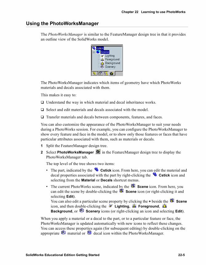
Chapter 22 Learning to use PhotoWorks
Using the PhotoWorksManager
The PhotoWorksManager is similar to the FeatureManager design tree in that it provides an outline view of the SolidWorks model.
The PhotoWorksManager indicates which items of geometry have which PhotoWorks materials and decals associated with them.
This makes it easy to:
� Understand the way in which material and decal inheritance works.
� Select and edit materials and decals associated with the model.
� Transfer materials and decals between components, features, and faces.
You can also customize the appearance of the PhotoWorksManager to suit your needs during a PhotoWorks session. For example, you can configure the PhotoWorksManager to show every feature and face in the model, or to show only those features or faces that have particular attributes associated with them, such as materials or decals.1 Split the FeatureManager design tree.2 Select PhotoWorksManager in the FeatureManager design tree to display the
PhotoWorksManager tab.The top level of the tree shows two items:• The part, indicated by the Cstick icon. From here, you can edit the material and
decal properties associated with the part by right-clicking the Cstick icon and selecting from the Material or Decals shortcut menus.
• The current PhotoWorks scene, indicated by the Scene icon. From here, you can edit the scene by double-clicking the Scene icon (or right-clicking it and selecting Edit). You can also edit a particular scene property by clicking the + beside the Scene icon, and then double-clicking the Lighting, Foreground, Background, or Scenery icons (or right-clicking an icon and selecting Edit).
When you apply a material or a decal to the part, or to a particular feature or face, the PhotoWorksManager is updated automatically with new icons to reflect these changes. You can access these properties again (for subsequent editing) by double-clicking on the appropriate material or decal icon within the PhotoWorksManager.
SolidWorks Educational Edition Getting Started 22-5

Special Topics
Rendering an Image
Rendering an image with the PhotoWorks software is straightforward.1 Click Render on the PhotoWorks toolbar, or click PhotoWorks, Render.
The PhotoWorks software produces a solid, smooth-shaded rendering of the candlestick, against a default background scene consisting of a reflective tread-plate ‘floor’ and cork-patterned ‘walls’.The PhotoWorks - Default Material dialog is displayed, indicating that the part has been rendered with the default material, Polished Plastic. The default material can be applied to the model automatically for you, if you do not wish to create and apply a material yourself. (You can also set your own default material.)
2 Click Yes to apply this material to the model.The PhotoWorks - Default Scene dialog is displayed, indicating that the part has been rendered with the default scene, Shiny Tread Plate and Cork. The default scene can be applied to the model automatically for you, if you do not want to select or create a default scene yourself. (You can also set your own default scene.)
3 Click Yes to apply this scene to the model.4 Change the view orientation.
The view returns to the normal, SolidWorks, shaded view. 5 Click Render or PhotoWorks, Render again.
Each time you change the view, you need to render the image again.To abort a rendering, click Stop in the PhotoWorks - Render dialog box.
22-6

Chapter 22 Learning to use PhotoWorks
Using the PhotoWorks Render Wizard
The PhotoWorks Render Wizard guides you through the basic steps involved in creating a photo-realistic image. Key steps include the selection of PhotoWorks material and scene properties.
A material defines how the surface of a part reacts to light. Each material consists of properties that determine various aspects of its appearance, such as surface color and texture, reflectance, and transparency.
A scene consists of properties additional to those directly associated with the SolidWorks model. These include lighting, shadows, foreground and background effects, and scenery.1 Click Render Wizard on the PhotoWorks toolbar, or click PhotoWorks, Render
Wizard.
2 After reading the Welcome note, click Next to learn about the PhotoWorks material editor.The Manager tab on the PhotoWorks - Material Editor dialog box has two display panels:• A Material Archive tree, which lists all the material archives currently available• A material selection area, in which to view and select materials
3 Click the Show me buttons for an animated demonstration of how to select a material.4 In the Stock Procedural material archive, click the Metals class to display the
materials it contains.5 Click the Antique Brass material to select it, then click Apply.
6 On the Wizard dialog, click Next to learn about the PhotoWorks scene editor.The Manager tab on the PhotoWorks - Scene Editor dialog box has two display panels:• A Scene Archive tree, which lists all the scene archives currently available• A scene selection area, in which to view and select scene templates
7 Click the Show me buttons for an animated demonstration of how to select a scene.8 Click Next to proceed to the final dialog box of the Render Wizard, then click Finish.
The PhotoWorks software renders the candlestick with an antique brass finish.
NOTE: You can also select and apply a material in one operation by double-clicking the image in the material selection area.
SolidWorks Educational Edition Getting Started 22-7

Special Topics
Selecting a Material
Now add more realism to the candlestick by selecting a different material for it.
Notice that the PhotoWorksManager has been updated by the addition of an Antique Brass material icon to indicate the material currently associated with the candlestick.
1 Double-click Antique Brass (or right-click and select Edit).Alternatively, you can right-click the Cstick icon in the PhotoWorksManager and select Material, Edit, or you can click Materials on the PhotoWorks toolbar, or click PhotoWorks, Materials.Notice that the icon representing the material currently associated with the part is highlighted in the material selection area on the Manager tab whenever you open the material editor.
2 Select the Polished Brass material.The Preview window, to the right of the PhotoWorks - Material Editor dialog box, is updated to show how the part will appear when it is rendered.
3 Click Apply, then click Close.Notice that the PhotoWorksManager has been updated with a Polished Brass material icon, to indicate the change of material.
4 Click Render or PhotoWorks, Render.
The candlestick is rendered with a polished brass appearance. Notice how the base of the candlestick reflects its stem and the surrounding background.
5 Change the view orientation, then render again.Notice how the reflections change on the curved surfaces of the candlestick.
22-8

Chapter 22 Learning to use PhotoWorks
Previewing a Material
You can use the Preview window on the PhotoWorks - Material Editor dialog box to preview materials and material edits rapidly, before committing to a full-size render.
Various controls are provided to manipulate the behavior of the Preview window.1 Double-click Polished Brass in the PhotoWorksManager (or right-click and
select Edit).Now take a look at the Preview window.In the Rendering area just below the preview image, you have the following options for rendering the preview:• In Automatic mode , each time you change a material property, the preview
is rendered again.• In Manual mode , you can change as many properties as you want, then
render the preview once to incorporate all the changes. To render the preview in Manual mode, click Automatic mode . Click again to return to Manual mode.
• In Full mode , the PhotoWorks software uses photo-realistic rendering for the preview.
• In Interactive mode , the PhotoWorks software uses OpenGL rendering for the preview.
• In the Display components area, you can choose to display the Model, or you can choose a simpler geometric shape. Preview rendering is faster with a simpler shape that approximates that of the model, such as a Cylinder. For certain types of change, you may need to see the details on the model.
• Click Zoom to Fit to display the part full size in the Preview window.
• Click Zoom to Area to zoom in on a particular area of the Preview window by positioning the pointer over it, then clicking and dragging a bounding box to enclose the selected area.
• Click Rotate View to rotate the part by clicking and dragging in the Preview window.
NOTE: You can also use PhotoWorks OpenGL rendering in the active SolidWorks document window. Click Interactive Rendering on the PhotoWorks toolbar, or click PhotoWorks, Interactive Rendering.
SolidWorks Educational Edition Getting Started 22-9

Special Topics
• You can also choose to disable various material properties temporarily, such as reflectance and transparency, to further accelerate preview rendering.
Editing a Material
Now try editing the reflectance properties of the polished brass material that you applied previously to the candlestick.1 Click the Reflectance tab on the PhotoWorks - Material Editor dialog box.
The reflectance of a material defines its ‘finish’, and determines how it behaves in the presence of light. Notice that the Style is set to Conductor. The PhotoWorks software supports several reflectance styles.
2 Change the Style to Metal.Notice that the preview retains the brass color but is now rendered with a specular metallic appearance.
3 Change the Style to Glass.4 Click Apply, then click Close.5 Click Render or PhotoWorks, Render.
The candlestick is rendered with a realistic approximation of glass reflectance, including transparency, reflection, and refraction.
NOTE: The PhotoWorks - Material Editor dialog box is a modeless dialog. You can keep it open while selecting other SolidWorks geometry and reference objects.
22-10
Chapter 22 Learning to use PhotoWorks
Rendering a Sub-image
You can use sub-image rendering to constrain the PhotoWorks software to render a selected area or selected geometry within the active SolidWorks document window.1 Change the view orientation.2 Click Render Area on the PhotoWorks toolbar, or click PhotoWorks, Render
Area.3 Drag a window over the area to render.
The PhotoWorks software renders only the area you selected.4 Now edit the material again:
a) Double-click Polished Brass in the PhotoWorksManager (or right-click and select Edit).
b) On the Reflectance tab, set Mirror to 0.5, to make the surface of the material appear more reflective.
c) Click Apply, then click Close.5 Click Render Last on the PhotoWorks toolbar, or click PhotoWorks, Render
Last.The PhotoWorks software re-renders the sub-image that you selected previously. This is a useful facility for when you want to edit the properties of a single material but do not want to render the whole model. The last sub-image remains valid until you select a new sub-image.
6 Click Boss-Sweep1 in the FeatureManager design tree.7 Click Render Selection on the PhotoWorks toolbar, or click PhotoWorks,
Render Selection.The PhotoWorks software renders a sub-image of the selected geometry.
8 Change the view orientation again, then click Render Last or PhotoWorks, Render Last.The PhotoWorks software re-renders the Boss-Sweep1 feature. Again, this is a useful facility for when you want to ‘fine-tune’ the appearance of a particular feature, without having to render the whole model.
SolidWorks Educational Edition Getting Started 22-11

Special Topics
Saving an Image to File
You can save a PhotoWorks image to a file for use in design proposals, technical documentation, product presentations, and so on. The PhotoWorks software supports Bitmap (.bmp), TIFF (.tif), Targa (.tga), and JPEG (.jpg) formats, as well as PostScript (.ps) and the PhotoWorks image format (.lwi).1 First, change the candlestick material once again:
a) Double-click Polished Brass in the PhotoWorksManager (or right-click and select Edit).
b) Use the scroll bar in the material selection area to locate Silver Plate, then double-click it to select and apply the material.
2 Set view orientation to *Trimetric.
3 Click Render Image to File on the PhotoWorks toolbar, or click PhotoWorks, Render Image to File, to display a Save As dialog box.The PhotoWorks software suggests an image file name based on the name of the part, along with the extension appropriate to the selected image format. By default, the image will be stored in the same directory as the part.
4 (Optional.) Select a different file name, file type, or storage location for the image.5 (Optional.) Set the Image Size, by specifying the Width and Height.
By default, the PhotoWorks software sets the resolution of the image in Pixels, according to the width and height of the active SolidWorks document window. You can specify the Width and Height of the image in Centimeters or Inches if you find these units more convenient. If you want the image to retain its original proportions when you alter the Width or Height, select the Fixed aspect ratio check box.
6 (Optional.) Click Options to set options appropriate to the selected image format.7 (Optional.) Select the Prompt when render complete check box if you want the
PhotoWorks software to notify you when the image has been rendered to file.8 Click Save.
The PhotoWorks software renders the image to file.
22-12

Chapter 22 Learning to use PhotoWorks
Viewing an Image File
You can view previously saved images using the PhotoWorks image viewer. All the image formats available in the PhotoWorks software (except PostScript) are supported by this utility.1 Click View Image File on the PhotoWorks toolbar, or click PhotoWorks, View
Image File.2 Locate the image file that you saved from Saving an Image to File on page 22-12.
3 Click Open.
The PhotoWorks software loads the image file and displays it in a separate window. SolidWorks is disabled temporarily while viewing an image file
4 Close the PhotoWorks - Image Viewer window.5 Save and close the part.
NOTE: Select the Preview check box on the file browser if you want to preview the image file before opening. This is useful if you have several image files.
SolidWorks Educational Edition Getting Started 22-13
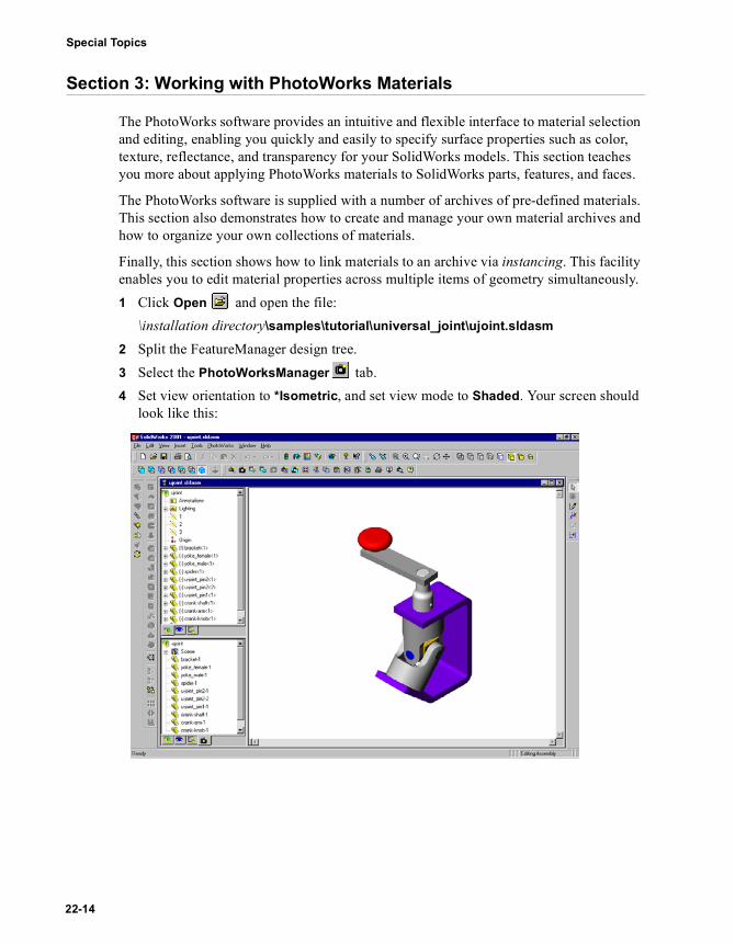
Special Topics
Section 3: Working with PhotoWorks Materials
The PhotoWorks software provides an intuitive and flexible interface to material selection and editing, enabling you quickly and easily to specify surface properties such as color, texture, reflectance, and transparency for your SolidWorks models. This section teaches you more about applying PhotoWorks materials to SolidWorks parts, features, and faces.
The PhotoWorks software is supplied with a number of archives of pre-defined materials. This section also demonstrates how to create and manage your own material archives and how to organize your own collections of materials.
Finally, this section shows how to link materials to an archive via instancing. This facility enables you to edit material properties across multiple items of geometry simultaneously.1 Click Open and open the file:
\installation directory\samples\tutorial\universal_joint\ujoint.sldasm
2 Split the FeatureManager design tree.3 Select the PhotoWorksManager tab.4 Set view orientation to *Isometric, and set view mode to Shaded. Your screen should
look like this:
22-14
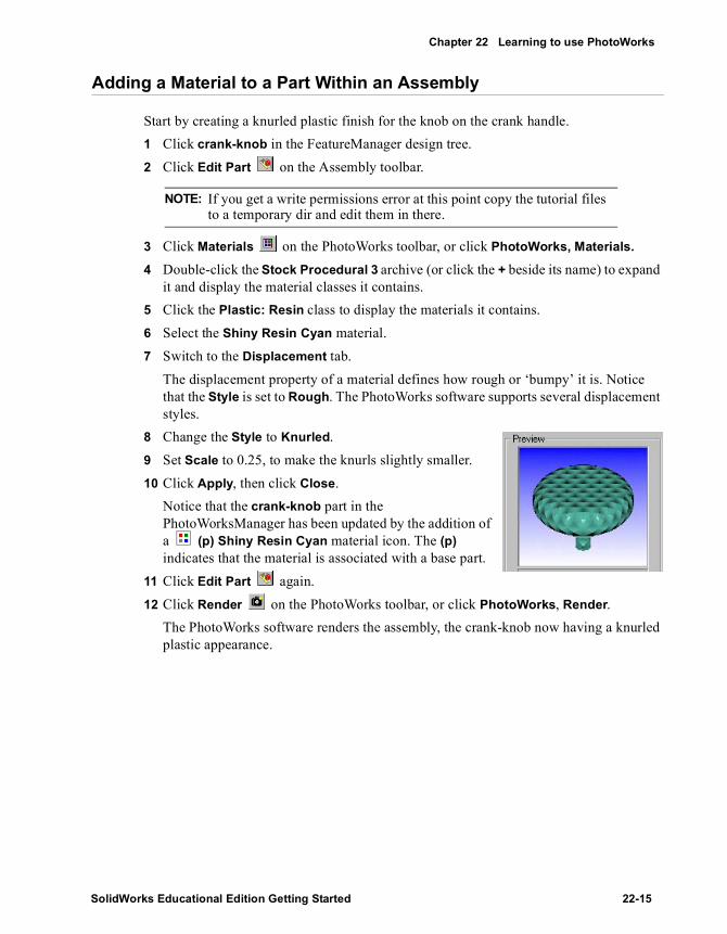
Chapter 22 Learning to use PhotoWorks
Adding a Material to a Part Within an Assembly
Start by creating a knurled plastic finish for the knob on the crank handle.1 Click crank-knob in the FeatureManager design tree.2 Click Edit Part on the Assembly toolbar.
3 Click Materials on the PhotoWorks toolbar, or click PhotoWorks, Materials.
4 Double-click the Stock Procedural 3 archive (or click the + beside its name) to expand it and display the material classes it contains.
5 Click the Plastic: Resin class to display the materials it contains.6 Select the Shiny Resin Cyan material.7 Switch to the Displacement tab.
The displacement property of a material defines how rough or ‘bumpy’ it is. Notice that the Style is set to Rough. The PhotoWorks software supports several displacement styles.
8 Change the Style to Knurled.9 Set Scale to 0.25, to make the knurls slightly smaller.10 Click Apply, then click Close.
Notice that the crank-knob part in the PhotoWorksManager has been updated by the addition of a (p) Shiny Resin Cyan material icon. The (p) indicates that the material is associated with a base part.
11 Click Edit Part again.12 Click Render on the PhotoWorks toolbar, or click PhotoWorks, Render.
The PhotoWorks software renders the assembly, the crank-knob now having a knurled plastic appearance.
NOTE: If you get a write permissions error at this point copy the tutorial files to a temporary dir and edit them in there.
SolidWorks Educational Edition Getting Started 22-15

Special Topics
Using Interactive Rendering to Preview Material Edits
You can use PhotoWorks interactive rendering to preview the effects of editing a material.
In this mode, the PhotoWorks software uses OpenGL rendering in the active SolidWorks document window. Although interactive rendering does not support all the advanced effects available within the PhotoWorks software, it does provide for rapid previewing of material edits.1 Click Interactive Rendering on the PhotoWorks toolbar, or click PhotoWorks,
Interactive Rendering.2 Click bracket in the FeatureManager design tree.3 Click Edit Part .4 Click Materials on the PhotoWorks toolbar, or click PhotoWorks, Materials.
5 Move the PhotoWorks - Material Editor dialog box so that it does not obscure the SolidWorks window.
6 Expand the Stock Procedural material archive, click the Metals class, then click the Steel material to select it.The Preview window is updated to show how the part will appear when it is rendered.
7 Click Apply.The PhotoWorks software updates the main window to show the application of the material.
8 In the material selection area, click Stainless Steel, then click Apply.The PhotoWorks software updates the main window to show the change of material.
9 Expand the Metal Textures archive, click Brushed, then double-click Galvanized to select and apply it.Notice that the bracket feature in the PhotoWorksManager has been updated by the addition of a (p) Galvanized material icon.
10 Click Render or PhotoWorks, Render.
22-16

Chapter 22 Learning to use PhotoWorks
Adding Materials to Individual Features and Faces
You can use the PhotoWorks material editor to apply different materials to individual features and faces. You can also use the PhotoWorksManager to cut, copy, and paste materials between selected features and faces.1 Hold down Ctrl and select Boss-Extrude1 and Fillet1 of the bracket in the
FeatureManager design tree.2 Click Materials on the PhotoWorks toolbar, or click PhotoWorks, Materials.
3 Expand the Stock Procedural archive, click Metals, then locate and double-click Machined Aluminum to select and apply it.Notice that the Boss-Extrude1 and Fillet1 features in the PhotoWorksManager have been updated by the addition of Machined Aluminum material icons.
4 Now edit the material associated with Boss-Extrude1, then copy and paste the change to Fillet1, via the PhotoWorksManager:a) Double-click the Machined Aluminum icon beneath Boss-Extrude1 in the
PhotoWorksManager.b) Locate and double-click Chrome Plate to select and apply it. Close the materials
editor.c) Right-click Chrome Plate in the PhotoWorksManager and select Copy.d) Right-click the Machined Aluminum icon beneath Fillet1 in the
PhotoWorksManager and select Paste.5 Now edit the material on a single face:
a) Select the flat face on the top of the bracket.b) Click Materials on the PhotoWorks toolbar, or click PhotoWorks, Materials.c) Expand the Metal Textures archive, click Brushed, then double-click Brushed 1
to select and apply it.Notice that the Shell1 feature in the PhotoWorksManager has been updated by the addition of a <Face> icon, with an associated Brushed 1 material icon.
6 Now copy the Brushed 1 material and paste it onto another face:a) Right-click the Brushed 1 icon and select Copy.b) Select another face of the bracket.c) Click Paste Material on the PhotoWorks toolbar, or click PhotoWorks, Paste
Material.7 Click Edit Part again.8 Click Render or PhotoWorks, Render.9 Save the assembly.
NOTE: When you edit the material on selected features or faces, the Preview window displays the selected geometry only, rather than the whole part or assembly.
SolidWorks Educational Edition Getting Started 22-17
Special Topics
Creating a Material Archive
With the PhotoWorks Material Manager you can create your own material archives.
You can archive both procedurally defined (solid) and texture-mapped (wrapped) materials, and you are free to organize the contents of each archive to suit your needs. For example, you may want to create material classes that classify materials according to their inherent properties (metal, plastic, stone, fabric, and so on). Alternatively, you may want to store all the materials that relate to a particular project or model in a class of their own.1 Click Materials on the PhotoWorks toolbar, or click PhotoWorks, Materials.2 Click Create Archive to display the Create Archive dialog box.3 Type My Materials in the File name box, choose the location of the .pma file in which
to store the archive, then click Save.
The PhotoWorks software appends a new material archive, My Materials, containing an empty Untitled material class to the Material Archive tree.
4 Click-pause-click Untitled, and rename it to Universal Joint.The PhotoWorks software updates the symbol denoting the archive to indicate that the class has been renamed.
5 Click the My Materials archive to select it, then click Save Archive .6 Click Close.
NOTE: By default, the PhotoWorks software uses the root directory on your drive to store your material archives. You may want to create a new directory in which to store material archives.
22-18
Chapter 22 Learning to use PhotoWorks
Archiving a Procedurally Defined Material
Although it is not possible to edit the pre-defined material archives supplied with the PhotoWorks software, it is possible to add a copy of any pre-defined material to a material archive of your own. You can then edit the properties of your copy of the material to suit the needs of a particular project or model.1 Click Materials on the PhotoWorks toolbar, or click PhotoWorks, Materials.2 Expand the My Materials archive.3 Now expand the Stock Procedural archive, then click Metals.4 Drag the Polished Brass material and drop it on the Universal Joint class when the
class is highlighted.The PhotoWorks software appends a copy of the Polished Brass material to the Universal Joint class.
5 Click-pause-click Polished Brass, and rename it to Yoke.6 Click the My Materials archive to select it, then click Save Archive .7 Click Close.
The PhotoWorks software notifies you that the current material selection has changed, and asks whether you want to apply this material.
8 Click No. (You will apply this material, and edit its definition, later in this tutorial.)
SolidWorks Educational Edition Getting Started 22-19

Special Topics
Archiving a Texture-Mapped Material
You can archive your own texture-mapped materials. For example, these may include scanned bitmaps of paint swatches, metal finishes, decals, labels, and company logos.1 Click Materials on the PhotoWorks toolbar, or click PhotoWorks, Materials.2 Expand the My Materials archive, and click the Universal Joint class.3 Click Create Material (from Image File) in Archive to display the PhotoWorks –
Add Texture Materials dialog box.4 Locate the file:
\installation directory\samples\tutorial\photoworks\textures\tex_tile.bmp
5 Click Add, then click Close.The PhotoWorks software appends a new texture-mapped material to the class, based on the image file. The material is given the image filename, minus the three-letter filename extension.
6 Click the My Materials archive to select it, then click Save Archive .7 Click Close.
The PhotoWorks software notifies you that the current material selection has changed, and asks whether you want to apply this material.
8 Click No.9 Close the assembly.
22-20

Chapter 22 Learning to use PhotoWorks
Linking Materials to an Archive via Instancing
You can use instancing to apply identical copies of any PhotoWorks material to multiple items of SolidWorks geometry. All instances of a given material share the same material definition, which is recorded in the material archive to which they are linked.
In this exercise, you apply the Yoke material that you created previously to two separate parts within the Universal Joint assembly.1 Open the file:
\installation directory\samples\tutorial\universal_joint\yoke_male.sldprt
2 Click Materials on the PhotoWorks toolbar, or click PhotoWorks, Materials.
3 Expand the My Materials material archive, click the Universal Joint class, then click the Yoke material to select it.
4 (Optional.) Press F3.The PhotoWorks software re-renders the thumbnail image in the archive to match the image displayed in the Preview window.
5 Select the Link to Archive check box.The PhotoWorks software notifies you that instancing the material will apply the properties from the shared material definition in the linked material archive.
6 Click Yes to proceed with the instanced material.7 Click Apply, then click Close.8 Save the part, then close it.9 Open the file:
\installation directory\samples\tutorial\universal_joint\yoke_female.sldprt
10 Repeat steps 2 through 8, above.Both the yoke_male and yoke_female parts now share identical instances of the Yoke material.
SolidWorks Educational Edition Getting Started 22-21

Special Topics
Editing a Shared Material Instance Definition
Any edits that you make to a shared material instance definition are applied automatically to all instances of the material. This feature enables you to alter material properties across multiple items of geometry simultaneously.
Try editing the definition of the Yoke material that you applied in the previous exercise.1 Open the file:
\installation directory\samples\tutorial\universal _joint\ujoint.sldasm
2 Click Render or PhotoWorks, Render.Notice that the yoke_male and yoke_female parts are rendered with the polished brass Yoke material that you created previously.
3 Click yoke_male in the FeatureManager design tree.4 Click Edit Part on the Assembly toolbar.5 Click Materials on the PhotoWorks toolbar, or click PhotoWorks, Materials.
6 In the Apply to list, select Archive.7 Click the Color tab.8 Under Colors, click Edit, select a color from the palette, then click OK.9 Click Apply.10 Click Yes to update the existing shared material definition.11 Click Close.12 Click Edit Part again.13 Click Render or
PhotoWorks, Render.Notice that the appearance of the Yoke material has changed on both the yoke_male and yoke_female parts.
14 Save and close the assembly.
22-22
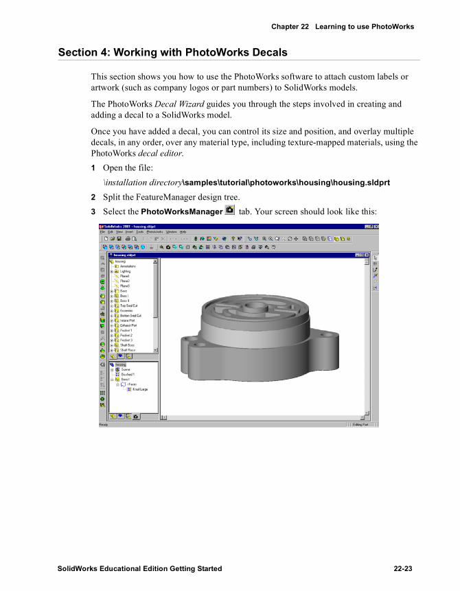
Chapter 22 Learning to use PhotoWorks
Section 4: Working with PhotoWorks Decals
This section shows you how to use the PhotoWorks software to attach custom labels or artwork (such as company logos or part numbers) to SolidWorks models.
The PhotoWorks Decal Wizard guides you through the steps involved in creating and adding a decal to a SolidWorks model.
Once you have added a decal, you can control its size and position, and overlay multiple decals, in any order, over any material type, including texture-mapped materials, using the PhotoWorks decal editor.1 Open the file:
\installation directory\samples\tutorial\photoworks\housing\housing.sldprt
2 Split the FeatureManager design tree.3 Select the PhotoWorksManager tab. Your screen should look like this:
SolidWorks Educational Edition Getting Started 22-23

Special Topics
Adding a Decal to a Face
Now attach a decal representing a part number.1 Select the large curved face on the Base.2 Click Decals on the PhotoWorks toolbar,
or click PhotoWorks, Decals.The PhotoWorks - Decal Editor dialog box is displayed. It includes:• A Decal Manager tree, which lists all
decals attached to the current part, feature, or face.
• A display area, in which to view the components of individual decals.
Notice that Create new decal with wizard is selected.3 Click Create New Decal .
The PhotoWorks - Decal Wizard is displayed.4 After reading the Welcome note, click Next to select a decal image.5 Click Browse, then locate and open the file:
\installation directory\samples\tutorial\photoworks\decals\pw_image.bmp
The image file contains the decal artwork – in this case, a simple part number.6 Click Next to create a decal mask.7 Select From file, then click Next.8 Browse to the file:
\installation directory\samples\tutorial\photoworks\decals\pw_mask.bmp
9 Click Next to view the complete decal, consisting of the image combined with the mask.
10 Click Next through to the Finished! dialog box of the wizard, then click Finish.The PhotoWorks software adds the new decal to the Decal Manager tree, giving it the name Decal1. The PhotoWorks software displays the components of the decal in the display area on the decal Manager tab. Also, Image, Mask, and Mapping tabs are added to the PhotoWorks - Decal Editor dialog box.
Select this face
22-24

Chapter 22 Learning to use PhotoWorks
Adjusting a Decal on a Face
Now use the PhotoWorks decal editor to fine-tune the scale and orientation of the decal on the face.1 With Decal1 still selected in the Decal Manager tree, click the Mapping tab.
Notice that the PhotoWorks software has created a Cylindrical mapping for the decal, with reference to the Selected face. However, the scale and orientation of the decal require some adjustment to position it correctly.
2 Under Scaling, drag the Around axis slider to a position halfway between Small and Large.
3 Set Along axis to 14.00mm.4 Under Orientation, set Rotation about axis to 85°.
The Preview window shows the decal correctly sized and centered on the face.5 Click Close.
The PhotoWorks software notifies you that the decal has changed, and asks whether you want to apply the change.
6 Click Yes.Notice that the PhotoWorksManager has been updated by the addition of a Decal1 decal icon, associated with the selected face.
7 Click Render on the PhotoWorks toolbar, or click PhotoWorks, Render.
The PhotoWorks software scales the decal and offsets it to the specified position on the face.
SolidWorks Educational Edition Getting Started 22-25

Special Topics
Section 5: Working with PhotoWorks Scenes
Composing a scene can improve visual realism by giving your model a more solid, 3D appearance. Rather than leaving the model floating in space, you can use shadows to anchor it against a simple geometric backdrop. You can apply PhotoWorks materials to the backdrop for added realism.1 Set view orientation to *Top, and rotate the part
to approximately the orientation shown. 2 Click Scene on the PhotoWorks toolbar, or
click PhotoWorks, Scene.The PhotoWorks - Scene Editor dialog box is displayed. It includes a scene Manager tab, from which to access scene archives, plus separate tabs for specific scene properties, and a Preview window with which to preview edits to these properties before rendering.The scene Manager tab has two display panels:• A Scene Archive tree, which lists all the scene archives currently available• A scene selection area, in which to view and select scene templatesNotice that the icon representing the scene currently associated with the part – in this example, the Default scene in the Basic class of the Stock Combinations archive – is highlighted in the scene selection area on the Manager tab whenever you open the scene editor.
3 Click the Lighting tab.4 Select the Display shadows check box.
The PhotoWorks software generates shadows for all SolidWorks directional lights, point lights, and spotlights in the scene.
5 In the Display components section of the Preview window, select the Shadows check box.Notice how the Preview window shows the raised boss casting a shadow onto the base of the housing. Internal self-shadowing of the part is also visible.
NOTE: You can also specify shadow properties for individual SolidWorks lights, using the PhotoWorks properties on the appropriate SolidWorks Light properties dialog boxes.
22-26

Chapter 22 Learning to use PhotoWorks
Adding an Image Background
Areas of the image not covered by parts of the SolidWorks model are known as image background. You can fill these areas with various patterns or images, thereby adding further visual interest and appeal to your PhotoWorks images.1 Click the Background tab on the PhotoWorks - Scene Editor dialog box.
Notice that the Style is set to Graduated. The PhotoWorks software supports several background styles.
2 Under Parameters, make sure that Top Color is selected, then click Edit.3 Select a color from the palette, then click OK.
The Preview window is updated to show the change.4 Modify the Bottom Color, if desired, observing the effect in the Preview window.5 Now change the Style to Clouds.6 Under Parameters, make sure that Scale is selected, then set Number to 2.7 Modify the Sky Color, Cloud Color, and Detail parameters, if desired, observing the
effect in the Preview window.Other background options include scaled or tiled images, or plain colors.The PhotoWorks - Scene Editor dialog box also includes a Foreground tab, from which you can select various styles of attenuation, to simulate atmospheric phenomena, such as fog and depth-cueing.
8 Click OK.9 Click Render on the PhotoWorks toolbar, or click PhotoWorks, Render.
SolidWorks Educational Edition Getting Started 22-27

Special Topics
Creating Background Scenery
The visual effectiveness of your presentation can be improved still further by setting the part against a geometric backdrop, rather than simply leaving it suspended in space.
With the PhotoWorks software, you can create simple background scenery consisting of a horizontal base plane and vertical sides surrounding the part. You can control the size and position of the scenery relative to the part, and select materials for the base and sides.
The scenery dimensions are calculated from the bounding box of the SolidWorks model. The scenery will never obscure the part. Only those planes visible behind the part will be displayed. Any reflective materials attached to the part will pick up and reflect color and texture from the background scenery.1 Click Scene or PhotoWorks, Scene, then click the Scenery tab.2 Under Base, do the following:
a) Select the Display check box.Notice that the default material, Polished Plastic, has been selected for the base.
b) Click Edit.The PhotoWorks - Material Editor dialog box appears.
c) Expand the Stone Textures material archive, click the Stone class, then click the Pink Marble material to select it.
d) Click the Mapping tab.e) Under Scaling, set both Width and Height to 65.00mm.f) Click OK.
3 Under Sides, do the following:a) Select the Display check box.
Notice that the default material, Polished Plastic, has been selected for the sides.b) Click Edit.
The PhotoWorks - Material Editor dialog box appears.c) Expand the Wood Textures material archive, click the Wood class, then click the
Mahogany material to select it.d) Click the Mapping tab.e) Under Scaling, set both Width and Height to 50.00mm.f) Click OK.
4 Under Base size, set both Base width and Base height to 125.00mm, to reduce the size of the base relative to the model.
5 Set Base offset to -25.00mm, to move the base closer to the model.6 Set Sides height to 75.00mm.7 Click OK.8 Click Render or PhotoWorks, Render.
22-28

23 SolidWorks Animator
In this chapter, you create animations and animation files of the claw model using SolidWorks Animator tools. This chapter discusses the following topics:
� Viewing the SolidWorks AnimationManager tab
� Animating a rotation with the Animation Wizard
� Animating an exploded view
� Scheduling motion
� Animating a collapsed view
� Creating a motion path
� Recording an animation
� Creating an animation file from screen captures
SolidWorks Educational Edition Getting Started 23-1

Special Topics
Getting Started with SolidWorks Animator
SolidWorks Animator is an add-in product, and it has its own AnimationManager tab.1 Click Open and open Claw-Mechanism.sldasm, found in the directory
\installation directory\samples\tutorial\animator.2 If Animator does not appear on the SolidWorks main menu bar, click Tools, Add-Ins.
The Add-ins dialog box appears.3 Select SolidWorks Animator and click OK.
The following Animator tools are now available:• The Animator menu appears in the menu bar.• A SolidWorks Animator Help Topics item appears in the Help menu.• The Animator Controller toolbar appears above the graphics area.
4 Click the AnimationManager tab at the bottom of the left pane.The AnimationManager tab is displayed when SolidWorks Animator is available. The AnimationManager display includes two sections. Each section lists the assembly components in a different manner.• Viewpoint - in the chronological order of the assembly creation• Schedule - in the chronological order of the animationItems (motion paths) are added to Schedule as you generate animations.
Animation Wizard
Create Path
Traverse Path
Edit Path
First
Previous Frame
Stop
Play
Next Frame
Last
Loop
Record Animation
Turn off screen capture
Turn on screen capture
23-2
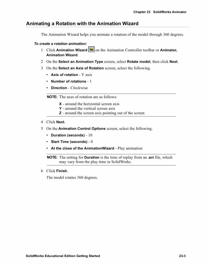
Chapter 23 SolidWorks Animator
Animating a Rotation with the Animation Wizard
The Animation Wizard helps you animate a rotation of the model through 360 degrees.
To create a rotation animation:1 Click Animation Wizard on the Animation Controller toolbar or Animator,
Animation Wizard.2 On the Select an Animation Type screen, select Rotate model, then click Next.3 On the Select an Axis of Rotation screen, select the following.
• Axis of rotation - Y axis• Number of rotations - 1• Direction - Clockwise
4 Click Next.5 On the Animation Control Options screen, select the following.
• Duration (seconds) - 10• Start Time (seconds) - 0• At the close of the AnimationWizard - Play animation
6 Click Finish.The model rotates 360 degrees.
NOTE: The axes of rotation are as follows:
X - around the horizontal screen axisY - around the vertical screen axisZ - around the screen axis pointing out of the screen
NOTE: The setting for Duration is the time of replay from an .avi file, which may vary from the play time in SolidWorks.
SolidWorks Educational Edition Getting Started 23-3

Special Topics
Animating an Exploded View
The assembly already contains an exploded configuration. You can animate this exploded view using the Animation Wizard. You add the Explode animation at the end of the Rotate animation.
To animate an exploded view:1 Click Animation Wizard on the Animation Controller toolbar or Animator,
Animation Wizard.2 On the Select an Animation Type screen, select Explode, then click Next.3 On the Animation Control Options screen, select the following.
• Duration (seconds) - 10• Start Time (seconds) - 10• At the close of the AnimationWizard - Play animation
4 Click Finish.The model rotates 360 degrees, then explodes the view.
NOTE: Since the Rotate path begins at 0 and ends at 10 seconds, you set the Explode animation to begin (Start Time) at 10 seconds, after the rotation is completed.
In the AnimationManager Schedule section, note that only one motion path is created for Rotate. For Explode, each component has a separate path, and each path has the same start time, as set in Start Time.
23-4

Chapter 23 SolidWorks Animator
Scheduling Motion
You can edit the Schedule motion paths manually and set the scheduled times so that the components explode one at a time.
To schedule motion manually:1 If necessary, click the AnimationManager tab , and click the beside Schedule
to expand the motion path schedules.At the end of each Schedule line, the starting and ending time of the motion appears in parentheses. Notice that all the Explode paths start and end at the same time. You want to schedule the parts individually so that they move one at a time to simulate a disassembly process: first the pins, then the claw, the rod, and the collar.
2 Select Pin-2 Explode, then click Edit Path on the Animation Controller toolbar.- or -Right-click Pin-2 Explode and select Edit Path.The Edit Path dialog box appears.
3 In the Change Timing section, change Start time (sec) to 20, then click OK.Pin-2 Explode appears at the bottom of the list with the timing (20.00, 30.00) showing that Pin-2 starts moving at 20 seconds and stops at 30 seconds.
4 Repeat steps 3 and 4 for the other parts except Pin-1 Explode. Leave Duration at 10 for all the parts. Set the following start times:
Pin-3 Explode 30Claw-1 Explode 40Con-Rod-1 Explode 50Collar-1 Explode 60
The Explode components appear in the Schedule list in chronological order.5 Click Play or Animator, Animation, Play.
The model rotates 360 degrees, then explodes one part at a time.
SolidWorks Educational Edition Getting Started 23-5

Special Topics
Playing the Animation
You can move through the animation using the Animator tools as follows:
Animating a Collapsed View
Animating a collapsed view is similar to animating an exploded view.
To animate a collapsed view:1 Click Animation Wizard or Animator, Animation Wizard.2 On the Select an Animation Type screen, select Collapse, then click Next.3 On the Animation Control Options screen, select the following.
• Duration (seconds) - 10• Start time (seconds) - 70• At the close of the AnimationWizard - Play Animation
4 Click Finish.The model rotates 360 degrees, explodes one part at a time, then collapses.
Action Result
Click Play or Animator, Animation, Play
Plays the animation from beginning to end
Click First or Animator, Animation, First
Moves to the beginning of the animation
Click Last or Animator, Animation, Last
Moves to the end of the animation
Click Previous Frame or Animator, Animation, Previous Frame
Single steps backwards from the end of the animation
Click Next Frame or Animator, Animation, Next Frame
Single steps forward from the beginning of the animation
23-6

Chapter 23 SolidWorks Animator
Creating a Motion Path
You use the Move Component tool on the Assembly toolbar to specify a motion path for animation.
To create a motion path:1 Select Collar-1 in either AnimationManager, FeatureManager, or the graphics area.2 Click Create Path or Animator, Create Path.
The Create Path dialog box appears.3 Click Add Path Point to set the current position as the initial position of the collar.4 Leave the dialog box open. On the Assembly toolbar, click Move Component .
5 In the graphics area, drag the collar up to a new position.6 In the dialog box, click Add Path Point to set the current position on the motion path.7 Select the Repeat initial path point as final path point check box so the collar returns
to the starting position at the end of the motion path.8 Set the Start time (sec) to 70 to place the motion path at the end of the previous
animation, then click Done.A warning message appears indicating that two or more paths are overlapping. By setting the starting time to 70, the new motion path overlaps the Collar-1 Collapse motion path.
9 Click OK and click Move Component to display AnimationManager.Note the red exclamation points beside all instances of Collar-1 in AnimationManager.
To fix the overlapping paths:
1 Select Collar-1-3, then click Edit Path on the Animation toolbar.- or -Right-click Collar-1-3 and select Edit Path.The Edit Path dialog box appears.
2 In the Change Timing section, change Start time (sec) to 80, then click OK.The warning exclamation points disappear.
To play the animation:
Click Play or Animator, Animation, Play. The model rotates, explodes, collapses, and finally the collar moves up and back down.
SolidWorks Educational Edition Getting Started 23-7

Special Topics
Recording an Animation
You can record an existing animation to a file of type .avi that you can play later.
To record an existing animation:1 Click Record Animation or Animator, Record Animation.
The Save Animation to File dialog box appears.2 Set Frames per second to 5, and click Save.3 In the Video Compression dialog box, click OK.
The animation plays as the recording occurs, which takes a few minutes.
To replay the animation from the .avi file:1 In Microsoft Explorer, find Claw-Mechanism.avi in the same directory as the model.2 Double-click the file name to play the animation in a separate window.
Creating an Animation File from Screen Captures
Use the part file Claw.sldprt to create an animation (.avi) file from screen captures.
To create an animation file from screen captures:
1 Open file Claw.sldprt, which is in the same directory as the claw assembly.2 Drag the rollback bar to before the first feature, Base-Extrude, so that nothing appears
in the graphics window.3 Click Turn on screen capture or Animator, Screen Capture, Turn on screen
capture.4 In the Save Animation to File dialog box, set Frames per second to 1, and click
Save.5 In the Video Compression dialog box, click OK.6 In the FeatureManager design tree, rebuild the part by dragging the rollback bar down
the tree one feature at a time.7 Click Turn off screen capture or
Animator, Screen Capture, Turn off screen capture.
To replay the animation from file:1 In Microsoft Explorer, find Claw.avi in the
same directory as the model.2 Double-click the file name to play the
animation in a separate window.
23-8
24
More about SolidWorks Functionality andAdditional Products
SolidWorks offers a seamless integration with the Windows environment, allowing you to benefit from its capabilities. It also allows you to include many add-in functions to enhance your productivity and efficiently manipulate the design environment.
This chapter briefly describes SolidWorks functionality and the functionality of its add-ins in the following areas:
� SolidWorks 2D Emulator
� Application Programming Interface (API)
� Collaboration
� eDrawings and eDrawings Professional
� FeatureWorks
� Import and Export
� Object Linking and Embedding (OLE)
� PhotoWorks
� Sheet Metal
� SolidWorks 3D Instant Website
� SolidWorks Animator
� SolidWorks Explorer
� SolidWorks MoldBase
� SolidWorks Piping
� SolidWorks Toolbox
� SolidWorks Utilities
SolidWorks Educational Edition Getting Started 24-1

Special Topics
2D Sketching and Command Emulator
If you are familiar with 2D drafting with AutoCAD® using a command line interface, you can continue sketching in the same way by using the SolidWorks 2D Command Emulator. This is available as a standard add-in. To activate the 2D Command Emulator, click Tools, Add-Ins and select SolidWorks 2D Emulator.
By default the command insertion window is docked at the bottom of the screen, but you can move it to another position. To turn the visibility of the command line window on or off, click 2D Command Emulator on the View menu. For more information about using the 2D Command Emulator, refer to the 2D Command Emulator online help.
SolidWorks Application Programming Interface
The SolidWorks Application Programming Interface (API) is an OLE programming interface to SolidWorks. The API contains hundreds of functions that can be called from Visual Basic, VBA (Excel, Access, and so on), C, C++, or SolidWorks macro files. These functions provide the programmer with direct access to SolidWorks functionality.
For a detailed description of the API and a list of all the new functionality added to the API since the last release of the SolidWorks software, refer to the API online help file. Click Help, SolidWorks API Help Topics to access the API help.
There is also a detailed description of the API functions on the SolidWorks Web page (http://www.solidworks.com/html/products/api).
Collaborating with Others
SolidWorks offers many tools that allow you to work in a multi-user environment or to share your design with others. These tools include:
� SolidWorks 3D Meeting. SolidWorks 3D Meeting is a SolidWorks application that interfaces with Microsoft Windows NetMeeting®. NetMeeting enables you to share SolidWorks (or other applications on your system) with other users over the Internet.
NOTE: The SolidWorks Student Edition contains many add-ins listed above. You can also purchase other add-ins at an additional cost.
To find out which add-ins are available with the SolidWorks Educational Edition, please visit http://www.solidworks.com/html/company/education.cfm.
View the online help for the installed add-ins in the SolidWorks Help menu for more information.
24-2

More about SolidWorks Functionality and Additional Products
� SolidWorks 3D Instant Website. SolidWorks 3D Instant Website allows you to create a web page from your SolidWorks application. The web page can include an embedded viewer and a comment section where multiple reviewers can offer opinions. Additionally, you can create your web page on a password-protected secure site hosted by SolidWorks. See Creating Web Sites on page 24-7 for more information.
� SolidWorks 3D PartStream. 3D PartStream.Net™ is an online Application Service Provider that lets you display and deliver configurable 3D computer-aided design (CAD) models to your customers over the Internet. Using 3D PartStream you can:• Configure, view, translate, and download CAD models with the 3D Content
Publisher.• Manage 3D content with 3D Model Manager to publish and maintain 3D data for
online product offerings.• Integrate 3D PartStream.Net with customer web sites via a standard API based on
Extensible Markup Language (XML).
� eDrawings. eDrawings is the first email-enabled communications tool designed to dramatically ease the sharing and interpretation of 2D mechanical drawings and 3D models. You can share eDrawings with anyone who has a Windows-based computer as the eDrawings Viewer comes bundled with the eDrawing as a single email attachment. See eDrawings and eDrawings Professional on page 24-4 for more information.
� SolidWorks Explorer. SolidWorks Explorer is a file management tool designed to help you easily perform such tasks as renaming, replacing, and copying SolidWorks documents. See Managing SolidWorks Documents on page 24-8 for more information.
� Feature Palette window. The Feature Palette window helps you organize and use library features, sheet metal forming tools, piping components, and other commonly used parts. You can store palette items anywhere on a network so that you can share them with your colleagues.
� Open from Internet server. You can open files residing on an Internet server. You can also modify then save files back to an Internet server.
� Copy Options Wizard. After you customize your SolidWorks software, you can use the Copy Options Wizard to copy information about the options set by one user and specify the same options on the machines of other users.
� Hyperlinks in notes. You can add an embedded hyperlink to a note, or you can add a floating hyperlink to any SolidWorks document. The hyperlink can be to a document on the Internet, on your local network, or on your own hard drive.
� Reload/Replace. You can refresh shared documents to reload the latest version, including any changes made by one of your colleagues. You can replace a referenced document with another document from anywhere on a network.
� Search paths. When you open a parent document, SolidWorks also loads into memory the other documents that are referenced in the parent document. You can set the
SolidWorks Educational Edition Getting Started 24-3

Special Topics
location where the SolidWorks software searches for referenced components to include shared folders for frequently used components.
eDrawings and eDrawings Professional
eDrawings eliminates the communication barriers that designers and engineers deal with daily. You can create eDrawing files from part, assembly, or drawing documents, then email these eDrawing files to others for instant viewing.
eDrawing files are compact and self-viewing. They have the following features:
� Ultra Compact Files - Send eDrawings using email. Substantially smaller in size than the original files, eDrawings make it practical to send files via email, even over slow connections.
� Built-in Viewer - View eDrawings immediately. Anyone with a Windows-based computer can view eDrawings. No additional CAD software or special viewers required. The eDrawing Viewer comes bundled with the eDrawing as a single email attachment.
eDrawings files are also significantly easier to understand than standard 2D drawings.
The following innovative features give you the capabilities that you need to overcome common barriers to effective 2D drawing communication:
� Virtual Folding - Open individual views in a drawing and arrange them in any way you desire, regardless of how the views were arranged in the original drawing. Virtual Folding enables the eDrawings recipient to print and export any subset of a drawing.
� Hyperlinking - Navigate through views automatically, ending searches for views or details. Simply click on the view annotation. That section view or detail is immediately added to your layout.
� 3D Pointer - Identify and match geometry in multiple views. It is much easier to interpret what you are looking at when comparing that same location in all other views.
� Animation - Demonstrate automatically how drawing views relate to each other.
24-4

More about SolidWorks Functionality and Additional Products
With the optional eDrawings Professional version, you have the following additional capabilities:
� Cross Sections - Create cross section views using a variety of planes to fully examine a model.
� Hide/Show - Hide or show assembly components.
� Markup - Markup files using clouds, text, or geometric elements. The markup elements are inserted in comments that are contained in reviews.
� Measure - Measure the distance between two entities.
� Move Components - Move components in an assembly or drawing file.
� Standard Views - Display standard orthographic views of models.
Identifying Features with the FeatureWorks Application
FeatureWorks is an application that recognizes features on an imported solid body in a SolidWorks part document. Recognized features are the same as features that you create using the SolidWorks software. You can edit the definition of recognized features to change their parameters. For features that are based on sketches, you can edit the sketches to change the geometry of the features. The FeatureWorks application is primarily intended for machined parts and sheet metal parts.
Importing and Exporting Files
You can import and export files using tools other than IGES, DXF, and STL shown in Chapter 21, “Importing Files / Using FeatureWorks Software.” Also included with the SolidWorks software are the following translation tools:
� Solid, Surface, or Wireframe Standards. ACIS®, DWG, STEP, and VDAFS
� Graphics Standards. CATIA® Graphics, Highly Compressed Graphics, HOOPS, JPEG, TIFF, Viewpoint®, Virtue, VRML and ZGL
� Direct Translators. Autodesk Inventor™, DXF 3D, Mechanical Desktop®, Parasolid™, Pro/ENGINEER®, Solid Edge™, and Unigraphics®
SolidWorks Educational Edition Getting Started 24-5

Special Topics
Object Linking and Embedding
You can use Object Linking and Embedding (OLE) to take advantage of features of other applications while in a SolidWorks document. You can also link or embed a SolidWorks part, assembly, or drawing document to another OLE-compliant application.
For example, OLE allows you to bring data generated by another application, such as a word processing application, into the SolidWorks application. Or, you might want to include a SolidWorks part in an another document, such as a product data sheet.
When using OLE, you can link or embed documents. Linking documents allows you to change the contents of a document in all places where it appears without having to edit each individual occurrence. Embedding a document allows you to keep any edits specific to the place in which you embedded it.
Rendering Models with the PhotoWorks Application
The PhotoWorks application is a photo-realistic rendering application that lets you create realistic images directly from SolidWorks models.
Using the PhotoWorks application, you can specify model surface properties such as color, texture, reflectance, and transparency. PhotoWorks is supplied with a library of surface textures (metals, plastics, and so on) and, in addition, you can scan in and use your own bit-mapped surface textures, materials, scenery, and logos. For more information, see Chapter 22, “Learning to use PhotoWorks.”
Engine sub-assembly: UAMZ
24-6

More about SolidWorks Functionality and Additional Products
Designing Sheet Metal
There are several additional tools available to reduce the design time when creating SolidWorks sheet metal documents. These tools include:
� Edge Flange - adds a flange to your sheet metal part at an edge that you select.
� Closed Corner - extends one face of a rip so it overlaps the other face of a rip. This is used with the Miter Flange feature.
� Bend Tables - allows you to specify the bend allowance or bend deduction values for a sheet metal part in a bend table. The bend table also contains values for bend radius, bend angle, and part thickness. Bend tables can be in a text file or Excel spreadsheet format.
For more information, see Chapter 18, “Sheet Metal Part.”
Creating Web Sites
SolidWorks 3D Instant Website allows you to create a web page from your SolidWorks application. The web page is based on a template and style that you can customize. The default templates that come with SolidWorks 3D Instant Website include:
� Embedded viewers for parts, assemblies, and drawings
� A comment section where multiple reviewers can offer opinions
� Your company's contact information with a link to its home page
Additionally, you can create your web page on a password-protected secure site hosted by SolidWorks. With this feature, you do not need your own web server to share your designs with others outside your company. You can also create your web page on a local or network drive.
Animating Assemblies with the SolidWorks Animator Application
With the SolidWorks Animator add-in, you can animate and capture motion of SolidWorks assemblies. The SolidWorks Animator application can generate Windows-based animations (.avi files) that you can play on any Windows-based computer. In conjunction with the PhotoWorks software, the SolidWorks Animator application can output photo-realistic animations.
The SolidWorks Animator application allows you to create a fly-around animation, an exploded view animation, or a collapsed view animation. Additionally, you can explicitly create motion paths for various components in your SolidWorks assembly.
SolidWorks Educational Edition Getting Started 24-7

Special Topics
Managing SolidWorks Documents
SolidWorks Explorer is a file management tool designed to help you easily perform such tasks as renaming, replacing, and copying SolidWorks documents.
SolidWorks Explorer is accessible from within the SolidWorks application. You can also open SolidWorks Explorer independently (by creating a shortcut on your desktop), and then open any SolidWorks documents from within SolidWorks Explorer.
To open SolidWorks Explorer from within the SolidWorks application, click Tools, SolidWorks Explorer. SolidWorks Explorer allows you to:
� View document dependencies for drawings, parts, and assemblies, using a tree structure.
� Copy, rename, or replace referenced documents. You have the option to find and update references to documents.
� View data and previews, or input data, according to the function you have active.
Use the following tools in SolidWorks Explorer to perform these tasks:
View any SolidWorks document on your system using the Preview tool. It is similar to using the shortcut menu in Windows Explorer for a Quick View.
View and edit specific, custom, or configuration-specific properties using the Properties tool. It also displays system data such as when the document was created and when it was last saved.
List all external references for SolidWorks documents using the Edit References tool.
Locate assemblies, drawings, or parts that reference a designated SolidWorks document using the Where Used tool.
Search for SolidWorks documents that meet a specified criterion, such as a custom property value, using the Properties Search tool.
List, rename, or delete configurations in an assembly or a part document using the Edit Configurations tool.
List, edit, and open any existing hyperlinks in a SolidWorks document using the Edit Hyperlinks tool.
24-8

More about SolidWorks Functionality and Additional Products
Creating Moldbase Assemblies
SolidWorks MoldBase helps create industry standard mold bases within SolidWorks. You select the vendor, style, size, and plate thickness, and SolidWorks MoldBase creates the mold base. Some of the features include:
� Components such as core pins, ejector pins, A and B plates, dowel pins, locating rings, bushings, and so on, are created automatically.
� Supported vendors include DME, PCS, Progressive, Superior, and HASCO®.
� The mold bases are fully defined assemblies that contain standard SolidWorks components with multiple configurations. You can edit the components like any other SolidWorks part or assembly document.
Building Piping Systems
The SolidWorks Piping software supports routing functionality for fabricated pipes. You model the path of the pipe by creating a 3D sketch of the pipe centerline. The software uses the centerline definition to generate the pipe and elbow components for the route.
The software makes extensive use of design tables to create and modify the configurations of routing components. The configurations are distinguished by different dimensions and properties.
You can add various types of fittings to the route, such as flanges, tees, crosses, and reducers. The fitting components must have configurations that match the pipe sizes.
Adding Standard Hardware
SolidWorks Toolbox includes a library of standard parts that are fully integrated with SolidWorks. Select the standard and the type of part you want to insert, then drag the component into your assembly.
You can customize the SolidWorks Toolbox library of parts to include your company's standards, or to include those parts that you refer to most frequently.
Solidworks Toolbox supports several international standards including ANSI, BSI, CISC, DIN, ISO, and JIS.
SolidWorks Educational Edition Getting Started 24-9

Special Topics
Additionally, SolidWorks Toolbox has several engineering tools including:
� Beam Calculator. Perform deflection and stress calculations on structural steel cross sections.
� Bearing Calculator. Perform bearing calculations to determine capacity ratings and basic life values.
� Cams. Create cams with fully-defined motion paths and follower types. The cam can be either circular or linear with 14 motion types from which to choose. You can also set how the track for the follower is cut, either as a blind cut or a cut through the entire cam.
� Grooves. Create industry standard O-Ring and Retaining ring grooves to your cylindrical model.
� Structural Steel. Bring the cross-section sketch of a structural steel beam into a part. The sketch is fully-dimensioned to match industry standard sizes. You can extrude the sketch in SolidWorks to create the beam.
Comparing Parts and Analyzing Geometry with SolidWorks Utilities
SolidWorks Utilities is a set of applications that allows you to examine and edit individual parts, and compare the features and solid geometry of pairs of parts. The utilities include the following tools:
� Geometry Analysis finds small faces, short edges, sliver faces, and so on.
� Compare Features compares the features of two similar parts, finding identical, modified, and unique features.
� Compare Geometry compares two solid parts to find their common volumes.
� Find/Replace/Suppress allows you to find features of a specific size or other characteristic you specify, and edit them in a batch mode.
24-10

Index
2D Command Emulator 24-23 point arcs 7-23D sketches 20-1–20-6
coordinate systems 20-2dimensions 20-2planes 20-2relations 20-2space handles 20-2virtual sharps 20-3
Aactivate view 15-3add
bosses 2-8components to an assembly 3-4dimensions to drawings 4-5dimensions to sketches 2-4drawing sheets 4-7mating relationships 3-6
align annotations 17-8align. See matingaligned section views 17-3alignment condition in assembly 12-10alternate position views 17-4ambient. See lightinganalyze a design 13-2anchor 16-4
animation 23-1–23-8collapse 23-6explode 23-4help 23-2motion path 23-3, 23-5, 23-7play 23-6record to file 23-8rotate 23-3schedule 23-2, 23-5screen captures to file 23-8SolidWorks Animator 23-1toolbar 23-2viewpoint 23-2wizard 23-3
AnimationManager tab 23-2annotations 17-8
align 17-8area hatch 17-8balloons 16-6blocks 17-8center marks 17-8cosmetic threads 17-8datum feature symbols 15-7datum targets 17-8folder 6-9geometric tolerance symbols 15-7hide/show 17-8hole callouts 17-8multiple 17-8
SolidWorks Educational Edition Getting Started Index - 1

notes 15-9stacked balloons 17-8surface finish symbols 15-7weld symbols 17-8
anti-aliasing 22-4Application Programming Interface (API) 24-2arcs
3 point 7-23D sketches 20-2centerpoint 10-2tangent 7-3
area hatch 17-8arrays. See patternsassemblies 3-1–3-7, 12-1–12-19
analysis of dependencies 13-2bottom-up design 13-2collapse 12-18configurations 14-6create 3-4create components in context 13-13design in context 13-3drag parts from another window 12-4drag parts from Windows Explorer 12-5explode 12-17features 14-4hole wizard 11-12insert components from files 12-11lightweight components 12-3mating components 3-6, 12-6molds 19-6origins 3-4, 12-4overview 3-2resolved components 12-3section drawing view 17-3top-down design 13-2
attach dimensions 21-5automatic geometric relations 7-6auxiliary views 17-2axes
animation rotation 23-3temporary 7-5
Bbackgrounds
abstract 22-27apply with PhotoWorks 22-27floors and walls 22-28
balloonsinsert 16-6options 16-2
base featurescreate 2-6depth 2-6end type 2-6lofts 8-5revolve 7-4
bends in sheet metal 18-5bill of materials 16-1–16-6
anchor 16-4balloons 16-6custom properties 11-2edit 16-5insert 16-3move 16-4properties 16-3save 16-6
blocks 17-8bolts and screws 14-4BOM. See bill of materialsbosses
add 2-8lofts 8-6sweeps 7-8
box selection 6-12broken views 17-3buttons, middle mouse 6-13
Ccam-follower mates 14-2cavities
create 19-7scaling factor 19-8
center marks 17-8centerlines 7-4, 15-3centerpoint arcs 10-2chain dimensions 15-6chamfers 11-7check entity 11-2circles 2-8circular patterns
create 9-9definition 9-1equal spacing 10-9spacing 9-9total instances 9-9
Index - 2

collaboration 24-2collapse
animation 23-6assemblies 12-18FeatureManager design tree 12-5
Collision Detection 14-6color 3-4compare geometry 24-10compare parts 24-10components
add from another window 3-4, 12-4add from file 12-11add from Windows Explorer 12-5copy 14-3derived 19-9lightweight 12-3mirror 14-3patterns 14-4properties 13-12resolved 12-3
ConfigurationManager 1-4, 5-8, 6-6configurations 5-1–5-9
assembly 14-6design tables 5-8
confirmation corner 6-7constrain all 21-5constraints. See relationscontext 13-13convert entities 3-3coordinate systems 11-4, 20-2copy
component instances 12-11components 14-3sketch geometry 8-4, 21-6
cosmetic threads 17-8countersunk hole 13-6create
assemblies 3-4base features 2-6bosses 2-9cavities 19-7circular patterns 9-9constant radius fillets 10-5cuts 2-10domes 13-15drawings 4-2face blend fillets 10-4fillets 2-13
linear patterns 9-8lofts 8-5parts 2-2planes 8-2revolve features 7-2rounds 2-12sweeps 7-5thin features 9-4variable radius fillets 10-6
crop views 17-4crosshatch 15-3curves 11-4cuts
extrude 2-10, 7-9sheet metal 18-5
Ddatum feature symbols 15-7datum targets 17-8Decal Editor 22-24Decal Wizard 22-24decals 22-23define relations 5-5delete
design tables 5-9holes in surfaces 11-16relations 5-5, 7-6
derive component part 19-9design portfolio 1-7design tables 5-1–5-9
close 5-7configurations 5-8control parameters 5-6delete 5-9edit 5-9embed in document 5-7insert 5-6
detail views 15-4, 17-4detailing ??–15-9, 16-1–16-6dialog box help 1-7diameter dimensions 2-9dimension-driven system 1-2dimensions
3D sketches 20-2attach 21-5chain 15-6circles 2-9diameter 2-9
SolidWorks Educational Edition Getting Started Index - 3

display 6-9drawings 4-5, 4-6, 17-7fonts 4-3linear 2-9link values 5-3, 19-4modify 2-5, 2-15, 6-17names 5-3ordinate 15-5properties 5-4, 15-6reference 15-6rename 5-4sketches 2-4standards 4-3tips 6-17witness lines 2-9
directional. See lightingdisplay
dimension names 5-3dimensions 19-4feature dimensions 5-2part section views 2-16relations 5-5, 7-6toolbars 1-6
document properties 6-14domes 13-15draft
extrude 19-2features 10-3
drag and drop 6-9drawing sheet formats. See sheet formatsdrawing views 17-2–17-5
activate 15-3aligned section 17-3alternate position 17-4auxiliary 17-2broken 17-3crop 17-4detail 15-4, 17-4projection 17-2relative 17-4section 15-3section of a section 17-3section of assembly 17-3
drawings 4-1–4-9, ??–15-9, 17-1–17-7create 4-2dimensions 4-5move views 4-4print 4-9
sheet metal 18-7sheets 4-7, 15-8standard 3 views 4-4templates 4-2views 4-4
DXF files 17-6, 21-4Dynamic Clearance 14-6dynamic previews 6-12
Eedges
hidden 8-6select 2-12
editanimation path 23-5assemblies 13-15bill of materials 16-5color 3-4design table in separate window 5-6design tables 5-9exploded view 12-19feature names 5-2parts in assemblies 19-7sheet formats 4-2sketch planes 8-4
eDrawings 24-4ellipses 7-7equations
folder 6-9, 13-6, 13-8patterns 9-10
Excelcreate bill of materials 16-1edit bill of materials 16-5edit design tables 5-9insert design tables 5-6save bill of materials 16-6
exploded viewsanimation 23-4assemblies 12-17drawings 15-8, 17-5
exportfiles 24-5
export STL files 21-8extend 13-8external references 19-8extrude
base features 2-6bosses 2-9, 20-5
Index - 4

cuts 2-10draft 19-2midplane 13-5offset from surface 10-8
Ffaces
hidden 8-6select 2-12
fasteners 14-4feature handles 2-15FeatureManager design tree 6-9–6-10
assemblies 3-4collapse 12-5definition 1-4flyout 6-10order of features 2-13sheet metal 18-2symbols 6-10tabs 6-10
FeaturePalette window 24-3features 7-1–7-10
accept 6-6assembly 14-4chamfers 11-7circular patterns 9-1copy 6-9defined 1-3display dimensions 5-2domes 13-15drafts 10-3fillets 2-13, 10-1–10-10, 11-8hide dimensions 5-2hole wizard 13-6linear patterns 9-1lofts 8-5, 11-5mirror 13-7mirror all 10-7move 6-9names 2-13, 5-2order 2-13properties 5-2rename 5-2ribs 11-7shells 2-14suppress 6-9sweeps 7-5, 11-6
thin 9-4unsuppress 6-9
FeatureWorks 21-3, 24-5file extensions
dxf 21-4igs, iges 21-2sldasm 3-7slddrw 4-5sldprt 2-7
filesanimation playback 23-8animation tutorial 23-2assemblies 3-7assembly tutorial 12-2case sensitivity 2-7drawings 4-5DXF tutorial 21-4import tutorial 21-2parts 2-7PhotoWorks tutorial 22-3
fillets 2-13, 10-1–10-10constant radius 7-10, 10-5face blend 10-4sketch 9-2, 20-4variable radius 10-6
flanges 18-2, 18-3flyout FeatureManager design tree 6-10fonts
dimensions 4-3notes 15-9
foreshortened radius 7-5formats. See sheet formatsfully defined sketches 2-4
Ggeometric tolerance symbols 15-7geometry analysis 24-10graphics area 1-4
Hhandles 1-5, 2-15, 20-2header/footer 6-14help
animation 23-2PhotoWorks 22-3SolidWorks 1-7
hidden in gray 2-12
SolidWorks Educational Edition Getting Started Index - 5

hidecomponents in drawings 17-5feature dimensions 5-2toolbars 1-6
hide behind plane 17-5highlight selections 6-12hole callouts 17-8hole wizard 11-11, 13-6hollow. See shells
IIGES files 21-2import 21-1–21-6
DXF files 17-6, 21-4files 24-5IGES files 21-2
import files 24-5in-context 13-13inferencing
assembly origin 12-4lines 7-2
inplace mating relation 13-13insert
balloons 16-6bill of materials 16-3components 3-4design tables 5-6exploded views 12-17lofts 8-5model items in drawings 4-5planes 8-2revolve features 7-4sweeps 7-8
insertingdome 13-15
interference, component 14-6Internet Explorer 6-2interrupted (broken) views 17-3isometric views 2-6
Jjog ordinate dimensions 15-5joining parts 14-5
Kkeyboard shortcuts 6-8
Llabel letters 15-5layers 17-6layout sketches 13-7leaders 15-9lighting 11-3lighting folder 6-9lightweight components 12-3line snap in 3D sketches 20-3line weights 6-14linear patterns
create 9-8, 20-5definition 9-1number of instances 9-8
lines 7-2, 20-4link dimension values 5-3, 19-4lofts 8-1–8-6
create 11-5definition 8-1insert 8-5order sketches 8-5planes 8-2profiles 8-3thin features 11-6
loop selection 6-12
Mmargins 6-14mategroups 12-4, 12-16materials
PhotoWorks 22-7transparency 19-6
mating 12-1–12-19automatic 12-12coincident 12-7components 3-6concentric 12-6distance 19-7inplace 13-13parallel 12-10relationships 3-6tangent 12-11test relationships 12-6types 14-2
Microsoft Visio Technical Edition 17-5middle mouse buttons 6-13midplane extrusions 13-5, 19-2
Index - 6

mirrorall 10-7, 18-3, 20-6components 14-3features 13-7multiple entities 9-7sheet metal bends 18-3sketching 19-2
modifydrawing dimensions 4-6feature dimensions 2-15part dimensions 2-5, 2-15
molds 19-1–19-10create mold base part 19-5cut 19-9insert model 19-6
mouse buttons 6-13move
bill of materials 16-4components 3-6drawing views 4-4
multiple views 6-3
Nname features 2-13, 5-2named views
drawings 4-8, 15-2sheet metal 18-8
newassemblies 3-4drawings 4-2parts 2-2
notes 15-9
Oobject linking and embedding (OLE) 24-6offset entities 3-3online help 1-7online tutorial 1-7open
drawing documents 4-2loop selection 6-12new assembly documents 3-4new part documents 2-2part documents 3-4tangency selection 6-12
optionsautomatically load lightweight 12-3balloons 16-2
bill of materials 16-2detailing 4-3, 17-7dimensioning standards 4-3dimensions 17-8display dimension names 5-3, 19-4drawings 15-4, 17-2edit design tables in separate window 5-6font, dimensions 4-3name feature on creation 5-2system 6-14
ordinate dimensions 15-5orientation dialog box 6-13origins
3D sketches 20-4assemblies 12-4sketches 2-3
output to image file, PhotoWorks 22-12over defined sketches 2-4overlay views 17-4
Pparts 2-1–2-16
create 2-2derived 11-2open new documents 2-2save 2-7
paths, sweep 7-5patterns 9-1–9-10
circular 9-9component 14-4definitions 9-1linear 9-8, 20-5mirror all 20-6sketch-driven 11-9skip instances 11-10table-driven 11-10
PhotoWorks 22-1–22-28, 24-6background scenery 22-27, 22-28create a backdrop 22-28decals 22-23fundamentals 22-2material selection 22-7, 22-28output to image file 22-12save image file 22-12shaded rendering 22-4view image file 22-13
piping 24-9
SolidWorks Educational Edition Getting Started Index - 7

planes3D sketches 20-2copy 8-3create 8-2edit sketch plane 8-4hole wizard 11-12offset 8-2reference geometry 11-3
plot drawings. See print drawingspoint. See lightingpointers 2-12, 3-4, 12-4, 20-4popup tooltips 6-13previews
dimensions 2-9dynamic 6-12section views 2-16shaded 6-12
printbackground 6-8options 6-14
print drawings 4-9profiles
area hatch 17-8detail views 15-4, 17-4lofts 8-3sweeps 7-8
projection views 17-2properties
bill of materials 16-3components 13-12dimensions 5-4, 15-6mass 11-2views 15-5
PropertyManager 1-4, 6-5, 6-15, 15-9
Rradius
fillets 2-12foreshortened 7-5
RapidDraft drawings 17-6rebuild 4-6, 6-10, 15-3rebuild errors 6-7recognize features 21-3record an animation 23-8rectangles 2-3referenced configuration 13-12references, external 19-8regenerate. See rebuild
relations3D sketches 20-2add 2-10coincident 7-8collinear 10-3constrain all 21-5coradial 19-3define 5-5display/delete 5-5, 7-6geometric 2-10horizontal 7-7midpoint 5-5verify 5-5
relationshipscoincident mating 12-7concentric mating 12-6distance mating 19-7inplace mating 13-13mating 3-6parallel mating 12-10tangent mating 12-11
relative drawing views 17-4rename
dimensions 5-4features 5-2
render 22-4, 22-6resolved components 12-3revolve features 7-2ribs 11-7rollback bar 6-9, 13-10rotate views 2-12, 17-5rounds 2-12
Ssave
assemblies 3-7bill of materials 16-6drawing sheet formats 4-2drawings 4-5parts 2-7PhotoWorks image file 22-12
scale function 11-11scales
detail views 15-4sheets 15-2
Scene Editor 22-26Scene Manager 22-26scenery 22-26
Index - 8

schedule, animation 23-2schematics 17-5section
drawing views 15-3, 17-3parts 2-16sweeps 7-7
selectfaces, edges, vertices 2-12hidden faces or edges 8-6other 8-6tool 2-3
selectionbox 6-12filters 6-11highlight 6-12loop 6-12open loop 6-12open tangency 6-12tangent 6-12
selection filter 3-3, 7-10setup 6-14shaded previews 6-12shared values 5-3sheet formats 4-2, 17-2sheet metal 18-1–18-8
base flanges 18-2bend tables 24-7bends 18-5closed corners 24-7cuts 18-5drawings 18-7edge flanges 24-7miter flanges 18-3tabs 18-4
sheets, drawing 4-7shells 2-14, 9-5shortcuts 6-6, 6-8show
components in drawings 17-5dimension names 19-4feature dimensions 5-2hidden edges in drawings 17-5
sketches 6-15–6-163 point arcs 7-23D 20-2centerlines 7-4centerpoint arcs 10-2defined 1-3
dimensions 2-4drawings 17-6ellipses 7-7entities 6-16extend 13-8fillets 9-2fully defined 2-4layout 13-7, 14-5lines 7-2loft profiles 8-3modes 6-15over defined 2-4status 2-4tangent arcs 7-3tools 6-16trim 7-3under defined 2-4
skins 6-15slice. See section viewsSmart Fasteners 14-4SmartMates 12-12, 14-2snap in 3D sketches 20-3SolidWorks 3D Instant Website 24-7SolidWorks 3D Meeting 24-2SolidWorks 3D PartStream 24-3SolidWorks Animator 23-1SolidWorks Explorer 24-8SolidWorks MoldBase 24-9SolidWorks Piping 24-9SolidWorks Utilities 24-10SolidWorks, customize 6-14space handles 20-2split
display 6-5window views 6-4
spot. See lightingstacked balloons 17-8standard
3 view drawings 4-4views 6-13
status bar 1-7, 2-4STL files 21-8sub-assemblies, flexible 14-3suppress features 6-9surface finish symbols 15-7surfaces 11-13
SolidWorks Educational Edition Getting Started Index - 9

sweepsdefinition 7-5multiple contours 11-6paths 7-5sections 7-7
symmetry mates 14-2system
options 6-14
Ttabs
AnimationManager 23-2ConfigurationManager 5-8FeatureManager design tree 1-4sheet metal 18-4
tangentarcs 7-3selection 6-12
templatesdocument 6-11drawing 4-2, 17-2
temporary axes 7-5thin features 9-4tip of the day 1-7toolbars 1-6
animation 23-2customize 6-5display or hide 1-6
tooltips 1-7, 6-13translation tools 24-5transparency 19-6trim 7-3tutorials 1-7
Uunder defined sketches 2-4unsuppress features 6-9update views 15-3
Vview image file, PhotoWorks 22-13viewpoint, animation 23-2views
drawing 4-4, 15-2drawing section 15-3exploded 15-8labels 15-5multiple 6-3
named 4-8, 15-2, 15-8part sections 2-16rotate 2-12split window 6-4update 15-3
virtual sharps 20-3Visio 17-5
Wweb
folders 6-11site 1-7, 24-7
weld beads 14-5weld symbols 17-8what’s wrong 6-7Windows Explorer 6-2wizards
animation 23-3DXF/DWG import 21-4
Zzoom 3-3, 3-5, 4-5
Index - 10