1 2 3 4 5 - unix.rulez.orgunix.rulez.org/~calver/haynes_manuals/citroen_bx/haynesbx5.pdf · 5...
TRANSCRIPT

2C
Chapter 2 Part C:K1G engine
Specifications are as for the type 150 engine (see Chapter 2A) except for the following:
GeneralModel application:
BX 14 after August 1988 . . . . . . . . . . . . . . . . . . . . . . . . . . . . . . . . . . . K1GMaximum power DIN (BHP) . . . . . . . . . . . . . . . . . . . . . . . . . . . . . . . . . . 72 at 5600 rpmMaximum torque DIN (lbf ft) . . . . . . . . . . . . . . . . . . . . . . . . . . . . . . . . . . 78 at 3400 rpm
ValvesValve clearance (cold):
Inlet . . . . . . . . . . . . . . . . . . . . . . . . . . . . . . . . . . . . . . . . . . . . . . . . . . . 0.20 mmExhaust . . . . . . . . . . . . . . . . . . . . . . . . . . . . . . . . . . . . . . . . . . . . . . . . 0.40 mm
Valve timingInlet opens* . . . . . . . . . . . . . . . . . . . . . . . . . . . . . . . . . . . . . . . . . . . . . . . 7º14’ BTDCInlet closes* . . . . . . . . . . . . . . . . . . . . . . . . . . . . . . . . . . . . . . . . . . . . . . 39º 45’ ABDCExhaust opens* . . . . . . . . . . . . . . . . . . . . . . . . . . . . . . . . . . . . . . . . . . . . 54º 30’ BBDCExhaust closes* . . . . . . . . . . . . . . . . . . . . . . . . . . . . . . . . . . . . . . . . . . . 0º 45’ BTDC*With valve clearance of 0.7 mm
CrankshaftEndfloat . . . . . . . . . . . . . . . . . . . . . . . . . . . . . . . . . . . . . . . . . . . . . . . . . . 0.052 to 0.452 mm
Cylinder linersProtrusion from block - without seal . . . . . . . . . . . . . . . . . . . . . . . . . . . 0.03 to 0.10 mmProtrusion difference between liners . . . . . . . . . . . . . . . . . . . . . . . . . . . 0.05 mm
Lubrication systemOil pressure at 90ºC (194ºF):
650 rpm . . . . . . . . . . . . . . . . . . . . . . . . . . . . . . . . . . . . . . . . . . . . . . . . 1.5 bar4000 rpm . . . . . . . . . . . . . . . . . . . . . . . . . . . . . . . . . . . . . . . . . . . . . . . 4.0 bar
Oil filter . . . . . . . . . . . . . . . . . . . . . . . . . . . . . . . . . . . . . . . . . . . . . . . . . . Champion F104Oil capacity - with filter change . . . . . . . . . . . . . . . . . . . . . . . . . . . . . . . 3.5 litres (6.2 pints)Dipstick minimum to maximum . . . . . . . . . . . . . . . . . . . . . . . . . . . . . . . 1.4 litres (2.5 pints)
Camshaft drivebelt - removal and refitting . . . . . . . . . . . . . . . . . . . . 6Cylinder head - dismantling, decarbonising, inspection and
reassembly . . . . . . . . . . . . . . . . . . . . . . . . . . . . . . . . . . . . . . . . . . . 14Cylinder head - removal and refitting . . . . . . . . . . . . . . . . . . . . . . . . 7Cylinder liners - checking protrusion . . . . . . . . . . . . . . . . . . . . . . . . . 17Engine - complete dismantling . . . . . . . . . . . . . . . . . . . . . . . . . . . . . 12Engine - complete reassembly . . . . . . . . . . . . . . . . . . . . . . . . . . . . . 18Engine dismantling - ancillary items . . . . . . . . . . . . . . . . . . . . . . . . . 10Engine dismantling - general information . . . . . . . . . . . . . . . . . . . . . 9Engine - examination and renovation . . . . . . . . . . . . . . . . . . . . . . . . 13Engine - initial start-up after overhaul . . . . . . . . . . . . . . . . . . . . . . . . 20
Engine - preparation for reassembly . . . . . . . . . . . . . . . . . . . . . . . . . 16Engine reassembly - general information . . . . . . . . . . . . . . . . . . . . . 15Engine - reconnection to transmission . . . . . . . . . . . . . . . . . . . . . . . 19Engine - separation from transmission . . . . . . . . . . . . . . . . . . . . . . . 11Engine/transmission - removal and refitting . . . . . . . . . . . . . . . . . . . 8General information and precautions . . . . . . . . . . . . . . . . . . . . . . . . 1Major operations possible with engine in vehicle . . . . . . . . . . . . . . . 3Major operations requiring engine removal . . . . . . . . . . . . . . . . . . . . 4Oil filter - removal and refitting . . . . . . . . . . . . . . . . . . . . . . . . . . . . . 2Valve rocker clearances - checking and adjustment . . . . . . . . . . . . . 5
2C•1
Specifications
Contents
Easy, suitable fornovice with littleexperience
Fairly easy, suitablefor beginner withsome experience
Fairly difficult,suitable for competentDIY mechanic
Difficult, suitable forexperienced DIYmechanic
Very difficult,suitable for expert DIYor professional
Degrees of difficulty
54321

Torque wrench settings Nm lbf ftCrankshaft pulley . . . . . . . . . . . . . . . . . . . . . . . . . . . . . . . . . . . . . . . . . . 102 74Camshaft sprocket . . . . . . . . . . . . . . . . . . . . . . . . . . . . . . . . . . . . . . . . . 82 59Big-end bearing cap . . . . . . . . . . . . . . . . . . . . . . . . . . . . . . . . . . . . . . . . 39 28Flywheel . . . . . . . . . . . . . . . . . . . . . . . . . . . . . . . . . . . . . . . . . . . . . . . . . 66 48Clutch pressure plate bolts . . . . . . . . . . . . . . . . . . . . . . . . . . . . . . . . . . . 15 11Distributor/fuel pump housing . . . . . . . . . . . . . . . . . . . . . . . . . . . . . . . . 8 6Camshaft thrust fork . . . . . . . . . . . . . . . . . . . . . . . . . . . . . . . . . . . . . . . . 17 13Thermostat housing . . . . . . . . . . . . . . . . . . . . . . . . . . . . . . . . . . . . . . . . 8 6Main bearing cap casting main bearing bolts:
Stage 1 . . . . . . . . . . . . . . . . . . . . . . . . . . . . . . . . . . . . . . . . . . . . . . . . 21 15Stage 2 . . . . . . . . . . . . . . . . . . . . . . . . . . . . . . . . . . . . . . . . . . . . . . . . Angle-tighten a further 45º
Oil pump . . . . . . . . . . . . . . . . . . . . . . . . . . . . . . . . . . . . . . . . . . . . . . . . . 8 6Sump . . . . . . . . . . . . . . . . . . . . . . . . . . . . . . . . . . . . . . . . . . . . . . . . . . . 8 6Main bearing cap casting to block . . . . . . . . . . . . . . . . . . . . . . . . . . . . . 8 6Coolant pump housing:
8 mm bolt . . . . . . . . . . . . . . . . . . . . . . . . . . . . . . . . . . . . . . . . . . . . . . 31 226 mm bolts . . . . . . . . . . . . . . . . . . . . . . . . . . . . . . . . . . . . . . . . . . . . . 51 37
Cylinder head bolts:Stage 1 . . . . . . . . . . . . . . . . . . . . . . . . . . . . . . . . . . . . . . . . . . . . . . . . 21 15Stage 2 . . . . . . . . . . . . . . . . . . . . . . . . . . . . . . . . . . . . . . . . . . . . . . . . Angle-tighten a further 240º
Timing belt tensioner . . . . . . . . . . . . . . . . . . . . . . . . . . . . . . . . . . . . . . . 21 15Timing cover . . . . . . . . . . . . . . . . . . . . . . . . . . . . . . . . . . . . . . . . . . . . . . 6 4Valve cover . . . . . . . . . . . . . . . . . . . . . . . . . . . . . . . . . . . . . . . . . . . . . . . 5 4Dipstick tube . . . . . . . . . . . . . . . . . . . . . . . . . . . . . . . . . . . . . . . . . . . . . . 15 11Oil pressure switch . . . . . . . . . . . . . . . . . . . . . . . . . . . . . . . . . . . . . . . . . 29 21Oil filter . . . . . . . . . . . . . . . . . . . . . . . . . . . . . . . . . . . . . . . . . . . . . . . . . . 15 11
1 General information andprecautions
General informationThe K1G engine is fitted to all Citroën BX 14
models after August 1988. It is an all-alloy unitand although the dimensions, clearances andtolerances are similar to those of the type150C engine dealt with in Chapter 2A, thereare several major differences. Thesedifferences include the camshaft drive, whichis of toothed belt type, and the oil pump,which is chain-driven from the crankshaft.
PrecautionsBecause of the unusual layout of the engine
and transmission systems, extra care andattention are necessary during maintenanceand overhaul procedures which, in manyinstances, differ from more conventionalsystems.
Read through the various Sectionsconcerned before tackling any job, andanalyse the instructions, so that any snags orpossible difficulties can be noted in advance.Because the sub-assembly castings are madefrom aluminium alloy it is of utmost importancethat, where specified, all fastenings aretightened to the correct torque and, in someinstances, in the correct sequence.
2 Oil filter - removal and refitting 2Refer to Chapter 1, Section 9.
3 Major operations possiblewith engine in vehicle
Note: Since the sump and cylinder head canbe removed in situ, it is possible to renew thepistons, liners and big-end bearings withoutremoving the engine. However, this is notrecommended, since the tasks can beperformed more easily with the engineremoved
The following components can be removedand refitted with the engine in the vehicle:a) Timing belt and camshaftb) Cylinder headc) Sump and oil pumpd) Clutch and flywheel (after removal of
gearbox)
4 Major operations requiringengine removal
The engine must be removed for thefollowing operations:a) Removal and refitting of the transmission b) Removal and refitting of the crankshaft
and main bearingsc) Removal and refitting of the piston and
connecting rod assemblies - see Note,Section 3
d) Renewal of the big-end bearings - seeNote, Section 3
5 Valve rocker clearances -checking and adjustment 3
Refer to Chapter 1, Section 21.
6 Camshaft drivebelt - removaland refitting 3
Note: If there is the slightest doubt about thecondition of the timing belt then it must berenewed.Note: The following operation can be carriedout with the engine in the vehicle.
Removal1 Disconnect the battery earth lead.2 Remove the hydraulic pump (outer) and thealternator (inner) drivebelts.3 Remove the rocker cover and remove therubber gasket from the cover (seeillustrations).4 Remove the two spacers and baffle platefrom the studs (see illustrations).5 Unbolt the upper timing cover, followed bythe intermediate cover and lower cover (seeillustrations).6 Turn the engine clockwise, using a socketon the crankshaft sprocket bolt, until the smallhole in the camshaft sprocket is aligned withthe corresponding hole in the cylinder head.Insert the shank of a close-fitting twist drillinto the holes (see illustration).7 Align the TDC holes in the flywheel andcylinder block rear flange, then insert a furthertwist drill or long bolt (see illustration).
2C•2 K1G engine

8 Loosen the timing belt tensioner roller nut(see illustration), turn the tensioner clockwiseusing a screwdriver or square drive in thespecial hole, then re-tighten the nut.9 Mark the normal direction of rotation on the
timing belt, then remove it from the camshaft,coolant pump, and crankshaft sprockets.
RefittingCaution: Take care not to kink or
contaminate the timing belt with oil10 Engage the timing belt with the crankshaftsprocket then, keeping it taut, feed it onto thecamshaft sprocket, around the tensionerpulley, and onto the coolant pump sprocket.11 Loosen the nut and turn the tensionerroller anti-clockwise by hand. Tighten the nut.12 Citroën dealers use the special toolshown (see illustration) to tension the timingbelt. A similar tool may be fabricated using an8.0 cm long arm and a 1.5 kg (3.3 lb) weight.The torque applied to the roller willapproximate 12 Kgf (10.5 lbf in). Pre-tensionthe timing belt with the tool and tighten thenut, then remove the timing pins and rotatethe crankshaft through two complete turns.Loosen the nut and allow the roller tore-position itself. Tighten the nut.13 If the special tool is not available, anapproximate setting may be achieved byturning the roller hub anti-clockwise, until it is
K1G engine 2C•3
2C
6.3a Removing a rocker cover nut 6.3b Removing rocker cover gasket 6.4a Remove rocker cover spacers(arrowed) . . .
6.6 Camshaft sprocket held at TDC 6.7 Using long bolt (arrowed) to align TDCholes in flywheel and cylinder block
6.5c Removing intermediate timing cover 6.5d Removing lower timing cover
6.8 Loosening timing belt tensioner rollernut
6.4b . . . and baffle plate 6.5a Unbolting upper timing cover 6.5b Removing upper timing cover
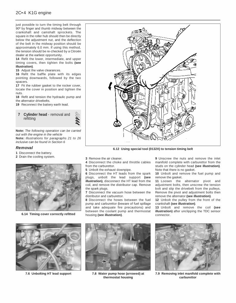
just possible to turn the timing belt through90º by finger and thumb midway between thecrankshaft and camshaft sprockets. Thesquare in the roller hub should then be directlybelow the adjustment nut, and the deflectionof the belt in the midway position should beapproximately 6.0 mm. If using this method,the tension should be re-checked by a Citroëndealer at the earliest opportunity.14 Refit the lower, intermediate, and uppertiming covers, then tighten the bolts (seeillustration).15 Adjust the valve clearances.16 Refit the baffle plate with its edgespointing downwards, followed by the twospacers.17 Fit the rubber gasket to the rocker cover,locate the cover in position and tighten thenuts.18 Refit and tension the hydraulic pump andthe alternator drivebelts.19 Reconnect the battery earth lead.
7 Cylinder head - removal andrefitting 3
Note: The following operation can be carriedout with the engine in the vehicleNote: Illustrations for paragraphs 21 to 26inclusive can be found in Section 6
Removal1 Disconnect the battery.2 Drain the cooling system. 3 Remove the air cleaner.
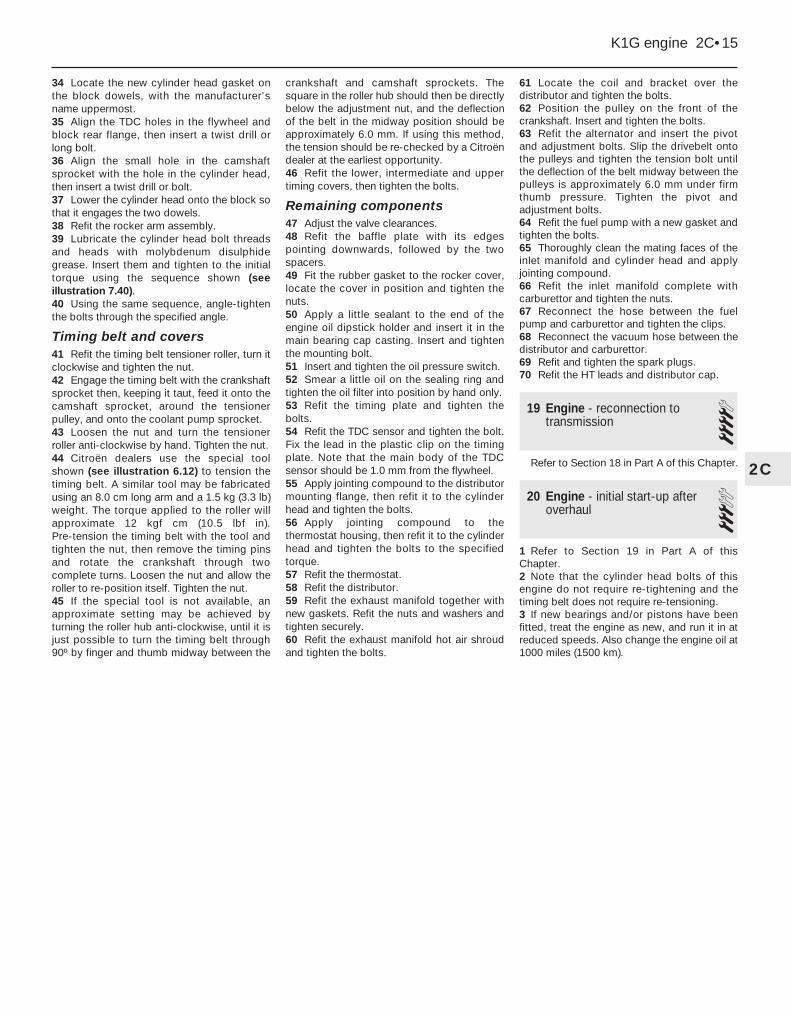
4 Disconnect the choke and throttle cablesfrom the carburettor.5 Unbolt the exhaust downpipe.6 Disconnect the HT leads from the sparkplugs, unbolt the lead support (seeillustration), disconnect the HT lead from thecoil, and remove the distributor cap. Removethe spark plugs.7 Disconnect the vacuum hose between thedistributor and carburettor.8 Disconnect the hoses between the fuelpump and carburettor (beware of fuel spillageand take adequate fire precautions) andbetween the coolant pump and thermostathousing (see illustration).
9 Unscrew the nuts and remove the inletmanifold complete with carburettor from thestuds on the cylinder head (see illustration).Note that there is no gasket.10 Unbolt and remove the fuel pump andremove the gasket.11 Loosen the alternator pivot andadjustment bolts, then unscrew the tensionbolt and slip the drivebelt from the pulleys.Remove the pivot and adjustment bolts thenremove the alternator (see illustration).12 Unbolt the pulley from the front of thecrankshaft (see illustration).13 Unbolt and remove the coil (seeillustration) after unclipping the TDC sensorconnector.
2C•4 K1G engine
7.6 Unbolting HT lead support
6.14 Timing cover correctly refitted
7.8 Water pump hose (arrowed) atthermostat housing
7.9 Removing inlet manifold complete withcarburettor
6.12 Using special tool (0132X) to tension timing belt

14 Unbolt the exhaust manifold hot airshroud.15 Unscrew the brass nuts, remove thewashers and remove the exhaust manifoldfrom the studs on the cylinder head. Removethe gaskets.16 Remove the distributor.17 Remove the thermostat, then unbolt thethermostat housing from the cylinder head(see illustration).18 Unbolt the distributor mounting flangefrom the cylinder head (see illustration).19 Unbolt the TDC sensor from the flywheelend of the cylinder block and unclip the leadfrom the timing plate (see illustration).20 Unbolt and remove the timing plate (seeillustration).21 Unscrew the nuts and remove the rockercover. Remove the rubber gasket from thecover.
22 Remove the two spacers and baffle platefrom the studs.23 Unbolt the upper timing cover, followedby the intermediate cover and lower cover.24 Turn the engine clockwise, using a socketon the crankshaft sprocket bolt, until the smallhole in the camshaft sprocket is aligned withthe corresponding hole in the cylinder head.Insert the shank of a close-fitting twist drillinto the holes.25 Align the TDC holes in the flywheel andcylinder block rear flange, then insert a furthertwist drill or long bolt.26 Loosen the timing belt tensioner roller nut,turn the tensioner clockwise using ascrewdriver or square drive in the specialhole, then re-tighten the nut.27 Mark the normal direction of rotation onthe timing belt, then remove it from the
camshaft, coolant pump, and crankshaftsprockets.28 Unscrew the tensioner nut and removethe tensioner roller.29 Progressively loosen the cylinder headbolts using the reverse sequence to thatshown for tightening, then remove all thebolts.30 Lift off the rocker arm assembly (seeillustration).31 Rock the cylinder head to free it from theblock, then lift it from the location dowels. Thetwo angled metal rods shown may be used forthis purpose (see illustrations).32 Remove the cylinder head gasket from theblock.33 Fit liner clamps (see Section 16 in Part Aof this Chapter) if it is not proposed to removethe pistons and liners.
K1G engine 2C•5
2C
7.11 Alternator pivot (A) adjuster (B) andtensioner (C) bolts
7.12 Unbolting crankshaft pulley 7.13 Ignition coil (arrowed) located abovedistributor
7.20 Timing plate (arrowed) 7.30 Removing rocker arm assembly 7.31a Using two metal rods to freecylinder head from cylinder block
7.17 Removing thermostat housing 7.18 Distributor mounting flange retainingbolts (arrowed)
7.19 TDC sensor mounting bolt (arrowed)

Refitting34 Clean the cylinder head and block jointfaces thoroughly. Also clean the cylinder headbolt holes.35 Locate the new cylinder head gasket onthe block dowels, with the manufacturer’sname uppermost (see illustration).36 Align the TDC holes in the flywheel andblock rear flange and insert a twist drill or longbolt.37 Align the small hole in the camshaftsprocket with the hole in the cylinder headand insert a twist drill or bolt (seeillustration).38 Lower the cylinder head onto the block sothat it engages the two dowels.39 Refit the rocker arm assembly.40 Lubricate the cylinder head bolt threadsand heads with molybdenum disulphidegrease. Insert them and tighten to the initialtorque using the sequence shown (seeillustration).41 Using the same sequence, angle-tightenthe bolts through the specified angle (seeillustration).42 Refit the timing belt tensioner roller, turn itclockwise and tighten the nut.43 Engage the timing belt with the crankshaftsprocket then, keeping it taut, feed it onto thecamshaft sprocket, around the tensioner
pulley, and onto the coolant pump sprocket.44 Loosen the nut and turn the tensionerroller anti-clockwise by hand. Tighten the nut.45 Citroën dealers use the special toolshown in illustration 6.12 to tension thetiming belt. A similar tool may be fabricatedusing an 8.0 cm long arm and a 1.5 kg (3.3 lb)weight. The torque applied to the roller willapproximate 12 Kgf (10.5 lbf in). Pre-tensionthe timing belt with the tool and tighten thenut, then remove the timing pins and rotatethe crankshaft through two complete turns.Loosen the nut and allow the roller tore-position itself. Tighten the nut.46 If the special tool is not available, anapproximate setting may be achieved byturning the roller hub anti-clockwise, until it isjust possible to turn the timing belt through90º by finger and thumb midway between thecrankshaft and camshaft sprockets. Thesquare in the roller hub should then be directlybelow the adjustment nut, and the deflectionof the belt in the midway position should beapproximately 6.0 mm. If using this method,the tension should be re-checked by a Citroëndealer at the earliest opportunity.47 Refit the lower, intermediate, and uppertiming covers, then tighten the bolts - seeSection 6.48 Adjust the valve clearances.
49 Refit the baffle plate with its edgespointing downwards, followed by the twospacers.50 Fit the rubber gasket to the rocker cover,locate the cover in position and tighten thenuts.51 Refit the timing plate and tighten thebolts.52 Refit the TDC sensor and tighten the bolt.Fix the lead in the plastic clip on the timingplate. Note that the main body of the TDCsensor should be 1.0 mm from the flywheel.53 Apply jointing compound to the distributormounting flange, then refit it to the cylinderhead and tighten the bolts.54 Apply jointing compound to thethermostat housing, then refit it to the cylinderhead and tighten the bolts to the specifiedtorque.55 Refit the thermostat.56 Refit the distributor.57 Refit the exhaust manifold together withnew gaskets. Refit the nuts and washers, andtighten securely.58 Refit the exhaust manifold hot air shroudand tighten the bolts.59 Locate the coil and bracket over thedistributor and tighten the bolts.60 Position the pulley on the front of thecrankshaft. Insert and tighten the bolts.
2C•6 K1G engine
7.31b Lifting cylinder head from cylinderblock
7.35 Cylinder head gasket correctlylocated
7.37 Camshaft sprocket held at TDC usingtwist drill
7.40 Cylinder head bolt tightening sequence 7.41 Angle-tightening cylinder head bolts

61 Refit the alternator and insert the pivotand adjustment bolts. Slip the drivebelt ontothe pulleys and tighten the tension bolt untilthe deflection of the belt midway between thepulleys is approximately 6.0 mm under firmthumb pressure. Tighten the pivot andadjustment bolts.62 Refit the fuel pump with a new gasket andtighten the bolts.63 Thoroughly clean the mating faces of theinlet manifold and cylinder head and applyjointing compound.64 Refit the inlet manifold complete withcarburettor and tighten the nuts.65 Reconnect the hose between the fuelpump and carburettor and tighten the clips.66 Reconnect the vacuum hose between thedistributor and carburettor.67 Refit and tighten the spark plugs.68 Refit the HT leads and distributor cap.69 Reconnect the exhaust downpipe.70 Reconnect the choke and throttle cablesto the carburettor.71 Refit the air cleaner.72 Replenish the cooling system.73 Reconnect the battery.
8 Engine/transmission -removal and refitting 4
Removal1 The engine/transmission is removed bylifting it upwards out of engine compartment.2 Remove the bonnet.3 Remove the battery.4 Raise the front of the car, and support itsecurely on axle stands placed under thebody sill jacking points.5 Drain the cooling system.6 Drain the engine oil.7 Drain the transmission oil.8 Disconnect the choke and throttle cablesfrom the carburettor (see illustration).9 Remove the air cleaner.10 Disconnect the fuel supply hose from thefuel pump, and the return hose from the T-union.11 Remove the radiator.12 Remove both driveshafts.13 Unbolt and remove the front downpipe
from the exhaust manifold, and also the frontsection of the exhaust system, noting thesupport bracket on the transmission.14 Pull out the rubber cotter pin anddisconnect the speedometer cable from thetransmission (see illustration).15 Disconnect the gearchange control rodsby prising the sockets off the balljoints with anopen-ended spanner (see illustration).16 Remove the bolt from the engine rearmounting (see illustration).17 Unbolt the rear mounting yoke and thedriveshaft support bearing bracket, thenremove them.18 Release the clips which hold thesuspension levelling pipeline to the undersideof the engine and transmission.19 Loosen the mounting and belt adjusterlink bolts on the hydraulic pump and removethe drivebelt.20 Set the suspension height control lever inthe “low” position and then gently release thescrew on the hydraulic pressure regulatorthrough one turn (see illustration).21 Disconnect the small pipe union on thehydraulic pressure regulator and the one on
K1G engine 2C•7
2C
8.15 Using an open-ended spanner(arrowed) to disconnect a gearchange rod
balljoint
8.16 Engine rear mounting and yoke 8.20 Hydraulic pressure regulator
A Pipe union B Pressure relief screw
8.8 Carburettor connections
A Choke cableB Throttle cable
C Distributor vacuum hose
8.14 Speedometer cable rubber cotter pin (arrowed)

the security valve. Release the fixing clips andwithdraw the disconnected section of pipelinefrom below the car, noting carefully itsrouting.22 Unbolt the hydraulic pump/regulatorassembly from the cylinder block bracket (seeillustration).23 Raise the assembly and rest it on thecrossmember with the hydraulic flexible hosestill connected.24 Disconnect the clutch cable from therelease lever on the transmission (seeillustration).25 Disconnect the heater hoses from theengine.26 Disconnect the heater hose from thecarburettor (see illustration).27 Disconnect the earth cables from thetransmission casing (see illustration).
28 Disconnect the wiring from the alternatorand the plug which serves the temperatureswitch, oil pressure switch and reversing lightswitch (see illustration).29 Connect a suitable hoist to the enginelifting eyes and take the weight of theengine/transmission.30 Unscrew the through-bolt of the left-handmounting, then unbolt and remove themounting bracket (see illustrations).31 Unscrew the through-bolt from theright-hand engine mounting (see illustration).32 Swivel the engine/transmission so that thetransmission faces towards the left-hand frontcorner of the engine compartment.33 Raise the hoist slowly and lift theengine/transmission out of the enginecompartment (see illustration).34 The transmission can be separated from
the engine after removing the followingcomponents:a) Starter motorb) TDC sensorc) Flywheel cover plated) Reversing light switch lead connections
35 Undo and remove the clutchbellhousing-to-engine bolts.
Refitting36 Refitting is a reversal of removal, butobserve the following points:a) Use a plastic protective sleeve to prevent
damage to the oil seal lips when fitting theright-hand driveshaft
b) Adjust the clutch cablec) Refill the engine and transmission with oild) Refill the cooling systeme) Tension the drivebelts
2C•8 K1G engine
8.22 Unbolting hydraulic pump/regulatorassembly
8.24 Clutch cable connection at releaselever
8.26 Heater hose connection atcarburettor (arrowed)
8.30b Removing left-hand enginemounting bracket
8.31 Right-hand engine mounting through-bolt (arrowed)
8.33 Lifting engine/transmission unit fromvehicle
8.27 Earth cables at transmission(arrowed)
8.28 Temperature switch/oil pressureswitch/reversing light switch wiring
connector (arrowed)
8.30a Left-hand engine mounting through-bolt (arrowed)

f) Top-up the hydraulic systemg) The use of self-locking pliers will facilitate
reconnection of the gearchange rodballjoints (see illustration)
9 Engine dismantling - generalinformation
Refer to Section 8 in Part A of this Chapter.
10 Engine dismantling - ancillaryitems
Refer to Section 9 in Part A of this Chapter.
11 Engine - separation fromtransmission 4
Refer to Section 10 in Part A of this Chapter.
12 Engine - complete dismantling 41 Disconnect the HT leads from the sparkplugs, unbolt the lead support, disconnect theHT lead from the coil, and remove thedistributor cap. Remove the spark plugs.2 Disconnect the vacuum hose between thedistributor and carburettor.3 Disconnect the hoses between the fuelpump and carburettor (beware of fuel spillageand take adequate fire precautions) andbetween the coolant pump and thermostathousing.4 Unscrew the nuts and remove the inletmanifold complete with carburettor from thestuds on the cylinder head. Note that there isno gasket.
5 Unbolt and remove the fuel pump, thenremove the gasket.6 Loosen the alternator pivot and adjustmentbolts, then unscrew the tension bolt and slipthe drivebelt from the pulleys. Remove thepivot and adjustment bolts, then remove thealternator.7 Unbolt the pulley from the front of thecrankshaft.8 Unbolt and remove the coil after unclippingthe TDC sensor connector.9 Unbolt the exhaust manifold hot air shroud.10 Unscrew the brass nuts, remove thewashers and remove the exhaust manifoldfrom the studs on the cylinder head. Removethe gaskets.11 Remove the distributor.12 Remove the thermostat, then unbolt thethermostat housing from the cylinder head.13 Unbolt the distributor mounting flangefrom the cylinder head.14 Unbolt the TDC sensor from the flywheelend of the cylinder block and unclip the leadfrom the timing plate.15 Unbolt and remove the timing plate.16 Unscrew and remove the oil filter, using astrap wrench if necessary.17 Unscrew and remove the oil pressureswitch.18 Unscrew the mounting bolt and pull the
engine oil dipstick holder from the mainbearing cap casting. Remove the dipstickfrom the holder (see illustration).19 Unscrew the nuts and remove the rockercover. Remove the rubber gasket from thecover.20 Remove the two spacers and baffle platefrom the studs.21 Unbolt the upper timing cover, followedby the intermediate cover and lower cover.22 Turn the engine clockwise, using a socketon the crankshaft sprocket bolt, until the smallhole in the camshaft sprocket is aligned withthe corresponding hole in the cylinder head.Insert the shank of a close-fitting twist drillinto the holes.23 Align the TDC holes in the flywheel andcylinder block rear flange, then insert a furthertwist drill or long bolt.24 Loosen the timing belt tensioner roller nut,turn the tensioner clockwise using ascrewdriver or square drive in the specialhole, then re-tighten the nut.25 Mark the normal direction of rotation onthe timing belt, then remove it from thecamshaft, coolant pump, and crankshaftsprockets.26 Unscrew the tensioner nut and removethe tensioner roller.27 Progressively loosen the cylinder headbolts using the reverse sequence to thatshown, then remove all the bolts.28 Lift off the rocker arm assembly.29 Rock the cylinder head to free it from theblock, then lift it from the location dowels.Two angled metal rods may be used for thispurpose.30 Remove the cylinder head gasket from theblock.31 Fit liner clamps (see Section 16 in Part Aof this Chapter) if it is not proposed to removethe pistons and liners.32 Progressively loosen the clutch pressureplate bolts and remove the pressure plate andfriction disc from the flywheel (seeillustration).
K1G engine 2C•9
2C
8.36 Reconnecting a gearchange rodballjoint
12.18 Unbolting dipstick holder upper mounting 12.32 Removing clutch pressure plate and friction disc

33 Unbolt the coolant pump housing fromthe side of the block and prise out the O-ring.34 Have an assistant hold the flywheelstationary with a wide-bladed screwdriverinserted between the starter ring gear teeth,
then unscrew the crankshaft sprocket boltand remove the hub/sprocket and timing beltguide plate (see illustrations).35 Using a screwdriver, prise the front oilseal from the block and main bearing casting(see illustration).36 Hold the flywheel stationary and unscrewthe flywheel bolts. Lift the flywheel from thedowel on the crankshaft rear flange.37 Prise out the crankshaft rear oil seal usinga screwdriver.38 Invert the engine and support it on blocksof wood.39 Unscrew the nuts and bolts securing thesump to the main bearing casting, thenremove it by carefully prising it free of thejointing compound (see illustration).40 Unbolt the oil pump and tilt it to releasethe drive sprocket from the chain (seeillustrations).
41 Support the block on its flywheel end.42 Mark the liners for position, starting withNo 1 (at the flywheel end). Similarly mark thebig-end bearing caps.43 Temporarily refit the crankshaft sprocketbolt and turn the crankshaft so that Nos 1 and4 pistons are at bottom dead centre (BDC).44 Unscrew the nuts and remove the big-endbearing caps (see illustration). Remove thelower big-end shells, keeping them identifiedfor position.45 Remove the clamps and withdraw theliners, complete with pistons, from the block(see illustration).46 Remove the liner bottom O-rings.47 Repeat the procedure for Nos 2 and 3pistons and liners.48 Invert the engine again and unscrew thebolts securing the main bearing cap casting tothe block (see illustrations).
2C•10 K1G engine
12.34a Removing crankshaft sprocket bolt . . .
12.34b . . . the hub/sprocket . . . 12.34c . . . and timing belt guide plate
12.44 Removing a big-end bearing cap 12.45 Removing a liner/piston assembly 12.48a Unscrew main bearing cap castingfront bolts . . .
12.39 Removing the sump 12.40a Unscrew oil pump retaining bolts . . .
12.40b . . . and remove oil pump
12.35 Prising out crankshaft front oil seal

49 Progressively unscrew the main bearingbolts and lift the main bearing cap castingfrom the block. Gently tap it with a wooden orsoft-headed mallet to release it. Prise out the
main bearing shells, keeping them identifiedfor location.50 Remove the oil pump sprocket and chainfrom the crankshaft (see illustration).
51 Lift the crankshaft from the block andremove the main bearing shells, keeping themidentified for location. Also remove theendfloat thrustwashers from No 2 mainbearing location (see illustrations).
13 Engine - examination andrenovation 4
General information1 Refer to Section 12 in Part A of this Chapter.
Camshaft drivebelt2 The drivebelt should be renewed when theengine is overhauled, or if it has becomecontaminated with oil. There is no specifiedrenewal mileage. When handling the timingbelt, do not bend it sharply as this maydamage the internal fibres.
Camshaft3 Refer to Section 12 in Part A of this Chapterbut note that there is no camshaft lubricationmanifold, as the camshaft runs in an oil bath.
All other components4 Refer to Section 12 in Part A of this Chapter.
14 Cylinder head - dismantling,decarbonising, inspection andreassembly 4
Dismantling1 Remove the twist drill from the camshaftsprocket, then hold the sprocket stationaryusing an oil filter strap wrench or tool asshown. Unscrew the bolt and remove thesprocket (see illustrations).2 Unbolt and remove the camshaft thrust fork(see illustration).3 Prise out the oil seal, and carefully withdrawthe camshaft from the cylinder head (seeillustrations).
K1G engine 2C•11
2C
12.48b . . . and side bolts (arrowed) 12.50 Removing oil pump chain fromcrankshaft
12.51a Removing a main bearing shell . . . 12.51b . . . and endfloat thrustwasher
14.2 Camshaft thrust fork (arrowed)14.1c . . . and remove bolt, washer andsprocket - note location peg and cut-out
(arrowed)
14.1a Using home-made tool to holdcamshaft sprocket stationary
14.1b Unscrew camshaft sprocket bolt . . .
14.3a Prise out camshaft oil seal . . .

4 Remove the valves and springs, keepingthem in order by inserting them in a cardhaving suitable holes punched in it, numberedfrom 1 to 8. Discard the valve stem oil seals(see illustrations).
Decarbonising5 Refer to Section 13 in Part A of thisChapter.
Inspection6 Refer to Section 13 in Part A of thisChapter.
Reassembly7 Refit the valves and springs with referenceto Section 13 in Part A of this Chapter.8 Oil the camshaft bearings and insert thecamshaft into the cylinder head.9 Refit the camshaft thrust fork, and tightenthe bolt.10 Dip the new oil seal in oil then press it intothe cylinder head until flush, using a metaltube or large socket and hammer.11 Refit the camshaft sprocket so that thelocation peg enters the cut-out. Insert andtighten the bolt while holding the sprocketstationary, using the method described inparagraph 1.
15 Engine reassembly - generalinformation
Refer to Section 14 in Part A of this Chapter.
16 Engine - preparation forreassembly 3
Refer to Section 15 in Part A of this Chapter.
17 Cylinder liners - checkingprotrusion 3
Refer to Section 16 in Part A of this Chapter.
18 Engine - complete reassembly 4Note: Maintain conditions of absolutecleanliness when reassembling the engine
Crankshaft1 With the cylinder block upside-down on thebench, press the main bearing upper shellsinto position. Note that the grooved bearingsare fitted to positions No 2 and 4.2 Smear a little grease on the thrustwashersand locate them each side of No 2 bearingwith their grooves facing outwards.3 Oil the bearings and lower the crankshaftinto position (see illustration).4 Check that the crankshaft endfloat is asgiven in the Specifications, using a feelerblade between a thrustwasher and thecrankshaft web. The thrustwashers are
available in four thicknesses.5 Fit the oil pump sprocket and chain to thefront of the crankshaft, locating the sprocketon the Woodruff key.6 Press the main bearing lower shells intoposition in the main bearing cap casting,noting that the grooved bearings are fitted topositions No 2 and 4.7 Apply jointing compound to the matingface, then lower the main bearing cap castinginto position over the crankshaft (seeillustrations). At the same time, feed the oilpump chain through the aperture.8 Insert the main bearing bolts dry, thentighten them evenly to the initial torquewrench setting. Angle-tighten the bolts by afurther 45º (see illustration)9 Refit the bolts securing the main bearingcap casting to the block, and tighten them tothe specified torque.
2C•12 K1G engine
14.3b . . . and withdraw camshaft 14.4a Compress valve spring and removesplit collets . . .
14.4b . . . the retainer . . .
18.3 Oiling main bearing shells
14.4c . . . the spring . . . 14.4d . . . the spring seat . . . 14.4e . . . and the valve

Pistons and liners10 Support the cylinder block on its flywheelend.11 Check that the lower big-end bearingshells are fitted to the big-end caps and theupper shells to the connecting rods.12 Oil the liner bores and piston rings.13 Position the piston ring end gaps at 120ºfrom each other, so that none is in line withanother.14 Fit a piston ring compressor to eachpiston in turn and push the pistons in theirrespective liners using a hammer handle (seeillustrations). Make sure that the arrows onthe piston crowns face the front (timing belt
end) of the liners.15 Fit the bottom O-rings to the liners, takingcare not to twist them.16 Check that the crankshaft rotates freely,then position Nos 1 and 4 crankpins at bottomdead centre (BDC). Oil the crankpins.17 Insert No 1 liner/piston into the block andguide the connecting rod big-end onto thecrankpin. Refit the big-end bearing cap andtighten the nuts evenly to the specified torque(see illustration).18 Check that the crankshaft rotates freelywhile holding the liner in position with aclamp. Temporarily refit the crankshaftsprocket bolt to turn the crankshaft.
19 Repeat the procedure to fit the remainingpistons and liners.
Oil pump20 Support the block upside-down on thebench.21 Check that the oil pump location pin isfitted to the main bearing casting, then refitthe oil pump, tilting it to engage the drivesprocket with the chain. Insert and tighten thebolts.
Sump22 Apply jointing compound to the matingfaces of the sump and main bearing casting.Refit the sump, insert the bolts and tightenthem to the specified torque.
Crankshaft rear oil seal23 Dip the new crankshaft rear oil seal inclean engine oil and locate it over the rear ofthe crankshaft (see illustration).24 Citroën dealers use a special tool (0132U)to fit the seal but it can be fitted by using theflywheel. Temporarily locate the flywheel onthe crankshaft using four bolts, then tightenthe bolts evenly until the flywheel contacts therear flange. Remove the flywheel and use ametal tube or block of wood to drive the oilseal fully into position.
K1G engine 2C•13
2C
18.14b Using a hammer handle to push apiston into its liner
18.17 Tightening a big-end bearing capnut
18.8 Angle-tightening main bearing capbolts
18.14a Fitting a piston ring compressor
18.23 Crankshaft rear oil seal located overrear of crankshaft
18.7a Apply jointing compound to crankcase mating face . . . 18.7b . . . then lower main bearing cap casting into position

Flywheel25 Apply locking fluid to the threads of theflywheel bolts. Locate the flywheel on thecrankshaft dowel then insert the bolts andtighten them to the specified torque whileholding the flywheel stationary with a
wide-bladed screwdriver inserted betweenthe starter ring gear teeth (see illustration).
Crankshaft front oil seal26 Support the engine upright.27 Dip the crankshaft front oil seal in cleanengine oil, locate it over the front of the
crankshaft and drive it in flush with the front ofthe block using a metal tube or socket (seeillustration). There is no seating, so take carenot to drive it in too far.28 Fit the oil seal flange, followed by thehub/sprocket. Insert the sprocket bolt andspacer, and tighten the bolt to the specifiedtorque while holding the flywheel stationary(see illustration).
Coolant pump housing 29 Refit the coolant pump housing, togetherwith a new O-ring, and tighten the bolts to thespecified torque.
Clutch friction disc and pressureplate 30 Locate the clutch friction disc andpressure plate on the flywheel with the dowelsengaged. Insert the bolts finger-tight.31 Centralise the friction disc using auniversal tool, or by making a wooden adapterto the dimensions shown (see illustrations).32 Tighten the pressure plate bolts evenly tothe specified torque (see illustration).
Cylinder head33 Clean the cylinder head and block jointfaces thoroughly. Also clean the cylinder headbolt holes.
2C•14 K1G engine
18.25 Applying locking fluid to a flywheelbolt
18.27 Crankshaft front oil seal locatedover front of crankshaft
18.28 Tightening crankshaft sprocket bolt
18.31a Clutch centralising tool dimensions
Dimensions in mm
18.31b Centralising clutch friction disc using a universal tool 18.32 Tightening a clutch pressure plate bolt
34 Locate the new cylinder head gasket onthe block dowels, with the manufacturer’sname uppermost.35 Align the TDC holes in the flywheel andblock rear flange, then insert a twist drill orlong bolt.36 Align the small hole in the camshaftsprocket with the hole in the cylinder head,then insert a twist drill or bolt.37 Lower the cylinder head onto the block sothat it engages the two dowels.38 Refit the rocker arm assembly.39 Lubricate the cylinder head bolt threadsand heads with molybdenum disulphidegrease. Insert them and tighten to the initialtorque using the sequence shown (seeillustration 7.40).40 Using the same sequence, angle-tightenthe bolts through the specified angle.
Timing belt and covers41 Refit the timing belt tensioner roller, turn itclockwise and tighten the nut.42 Engage the timing belt with the crankshaftsprocket then, keeping it taut, feed it onto thecamshaft sprocket, around the tensionerpulley, and onto the coolant pump sprocket.43 Loosen the nut and turn the tensionerroller anti-clockwise by hand. Tighten the nut.44 Citroën dealers use the special toolshown (see illustration 6.12) to tension thetiming belt. A similar tool may be fabricatedusing an 8.0 cm long arm and a 1.5 kg (3.3 lb)weight. The torque applied to the roller willapproximate 12 kgf cm (10.5 lbf in).Pre-tension the timing belt with the tool andtighten the nut, then remove the timing pinsand rotate the crankshaft through twocomplete turns. Loosen the nut and allow theroller to re-position itself. Tighten the nut.45 If the special tool is not available, anapproximate setting may be achieved byturning the roller hub anti-clockwise, until it isjust possible to turn the timing belt through90º by finger and thumb midway between the
crankshaft and camshaft sprockets. Thesquare in the roller hub should then be directlybelow the adjustment nut, and the deflectionof the belt in the midway position should beapproximately 6.0 mm. If using this method,the tension should be re-checked by a Citroëndealer at the earliest opportunity.46 Refit the lower, intermediate and uppertiming covers, then tighten the bolts.
Remaining components47 Adjust the valve clearances.48 Refit the baffle plate with its edgespointing downwards, followed by the twospacers.49 Fit the rubber gasket to the rocker cover,locate the cover in position and tighten thenuts.50 Apply a little sealant to the end of theengine oil dipstick holder and insert it in themain bearing cap casting. Insert and tightenthe mounting bolt.51 Insert and tighten the oil pressure switch.52 Smear a little oil on the sealing ring andtighten the oil filter into position by hand only.53 Refit the timing plate and tighten thebolts.54 Refit the TDC sensor and tighten the bolt.Fix the lead in the plastic clip on the timingplate. Note that the main body of the TDCsensor should be 1.0 mm from the flywheel.55 Apply jointing compound to the distributormounting flange, then refit it to the cylinderhead and tighten the bolts.56 Apply jointing compound to thethermostat housing, then refit it to the cylinderhead and tighten the bolts to the specifiedtorque.57 Refit the thermostat.58 Refit the distributor.59 Refit the exhaust manifold together withnew gaskets. Refit the nuts and washers andtighten securely.60 Refit the exhaust manifold hot air shroudand tighten the bolts.
61 Locate the coil and bracket over thedistributor and tighten the bolts.62 Position the pulley on the front of thecrankshaft. Insert and tighten the bolts.63 Refit the alternator and insert the pivotand adjustment bolts. Slip the drivebelt ontothe pulleys and tighten the tension bolt untilthe deflection of the belt midway between thepulleys is approximately 6.0 mm under firmthumb pressure. Tighten the pivot andadjustment bolts.64 Refit the fuel pump with a new gasket andtighten the bolts.65 Thoroughly clean the mating faces of theinlet manifold and cylinder head and applyjointing compound.66 Refit the inlet manifold complete withcarburettor and tighten the nuts.67 Reconnect the hose between the fuelpump and carburettor and tighten the clips.68 Reconnect the vacuum hose between thedistributor and carburettor.69 Refit and tighten the spark plugs.70 Refit the HT leads and distributor cap.
19 Engine - reconnection totransmission 4
Refer to Section 18 in Part A of this Chapter.
20 Engine - initial start-up afteroverhaul 3
1 Refer to Section 19 in Part A of thisChapter.2 Note that the cylinder head bolts of thisengine do not require re-tightening and thetiming belt does not require re-tensioning.3 If new bearings and/or pistons have beenfitted, treat the engine as new, and run it in atreduced speeds. Also change the engine oil at1000 miles (1500 km).
K1G engine 2C•15
2C