46 class electric locomotives · locomotive and stand by for hand brake adjustments and piloting of...
TRANSCRIPT

DEPARTMENT OF RAILWAYS : NEW SOUTH WALESMECHANICAL BRANCH
_________
46 CLASS ELECTRIC LOCOMOTIVES_______________________
GENERAL WORKING INSTRUCTIONSFOR FIREMEN – OBSERVERS
________
BY AUTHORITY
F. P. HEARDCHIEF MECHANICAL ENGINEER
JULY, 1958

Reprinted October 2003
HB 46WIFO58.DOC

INTRODUCTORY.
This manual, intended primarily for firemen-observers already employed on Electric locomotives,is also valuable to all employees in this classificationas an introduction to a comparatively new locomotivetype, the use of which will undoubtedly extend toother lines, in the near future.
There is also the aspect that normal promotionand progression in the service will naturally bringthe present fireman-observers to a point in theircareer where they must quality for the more exactingduties of driving this locomotive type.
In this latter regard it should be appreciatedthat the present group of firemen observers is nowbeing afforded an opportunity which was denied thepresent group of electric locomotive drivers in sofas as, that the fireman-observer may graduallyapproach the subject and at the same time improvehis grounding in the company of his driver.
This manual commences with an explanation ofthe duties and responsibilities of all firemen-observers currently employed.
Following this information a limited amount offundamental knowledge of electricity is provided,and then in progression, are descriptive items ofhow electric current is controlled, routed andgenerally employed.
There is additionally available to all membersof the Railways Institute a short informative courseon 46 class locomotives, which deals in more detailwith fundamentals, and the various circuits employed,together with the component machines and their functions.


INDEX.
Item 1. List of preparation, stabling and emergency duties. Multiple unit working. Inspections.
Item 2. Allowances, preparation, stabling.
Item 3. Standard Examination Questions.
Item 4. Electric current, its uses and the locations of High Tension current.
Item 5. Circuits. Circuit breakers, Switches, Fuses.
Item 6. Employment of High Tension (1,500 V) current on 46 class locomotives.
Item 7. The control circuit, its origins and purpose.
Item 8. Pantograph and Pantograph Control.
Item 9. Air hoses on 46 class locomotives and their employment and spare hose. equipment to be carried.
Item 10. Automatic alarms and safeguards.
...........

1
ITEM 1.
LIST OF PREPARATION, STABLING, ROAD AND EMERGENCY DUTIESTO BE PERFORMED BY FIREMEN WHEN EMPLOYED AS OBSERVERS ON'46' CLASS ELECTRIC LOCOMOTIVES.
PREPARATION DUTIES.
1. Unlock 4 doors, inspect kit and fire extin- guishers and report to driver.
2. Test all marker and head lights each end and report to driver.
3. Tidy cabs, light hand lamps.
4. Stand by machinery compartment for pantograph raising.
5. Stand by driver in No. 1 Cab and test whistle and window wipers and observe pantograph reaction for driver.
6. Transfer control and brake valve handles to No. 2 end, set and apply independent brake, place other handles on desk.
7. Test wipers and horns and lift hand brakes No. 2 end, and observe pantograph reaction.
8. Set up head and tall marker and/or discs.
9. Pilot locomotive as required to Traffic points.
STABLING DUTIES.
1. Apply hand brakes each end and extinguish hand lamps.
2. Lock three (3) cab doors.
3. Charge storage reservoir and close inlet and outlet P. and C. reservoir isolating cocks.
ROAD DUTIES.
1. Share with the driver the responsibility for hand and all fixed signals, including right-away on driver's side and watching departure of train from platform.

2
2. To assist driver in changing ends by operating marker lights and/or discs at each end.
3. Operating hand brakes as required.
4. Attending to the correct coupling and uncoupling of the locomotive.
5. Operating of the locomotive in confined areas.
6. Attend any other duties as directed by the driver.
7. Regular inspections from each side of cab of the train details with particular attention to risk of hot axle boxes and dragging brakes.
8. 60" interval inspections of battery charging ammeter.
9. 30" interval inspections of auxiliary machines, etc.
FIREMEN'S DUTIES ON 46 CLASS ELECTRIC LOCOMOTIVES.
ITEM ONE.
The fireman of the 46 class electric locomotivebeing relieved of the activities of generating steamand associated duties is therefore in a position togive considerable practical assistance, not only inthe normal course of train working, but to have theknowledge which will enable him to perform certainduties in emergencies.
PREPARATION.
The preparation of any locomotive is bestachieved by following the same routine at all times.Any omission in the preparation then becomes obvious,therefore at all times commence the preparation in theNo. 2 cab. The reason being the availability of thebattery switch for illumination of the locomotiveduring darkness. No. 2 cab is always indicated bythe high numbers on the axle boxes.
After entering No. 2 cab close the battery switch,check that the hand brake is on, check that the handlamp is filled, and light if necessary, check thatdetonators and red flags are available, check that thepressure in the fire extinguisher is 100 p.s.i.and report any deficiency to the driver, switch on all

3
head and marker lights and observe their efficiencyfrom the ground, being sure to again switch offunrequired lights to save battery drain.
In the corridor between No. 2 cab and themachinery compartment observe the presence of threemultiple unit jumper couplings. They should bebranded A, B and C. These couplings convey the lowtension current from one locomotive to another inmultiple working. Also in these corridors are:
Two small air hoses which connect the independent brake pipes of two or more locomotives.
One brake pipe end air hose, one main Reservoir pipe and air hose.
One sealed tool box. (If this seal is damaged or missing, report to driver).
In No. 1 cab make similar tests and inspectas in No. 2 cab.
Now remain in attendance to the driver sothat in the machinery compartment, assistance maybe given him in pantograph raising (initial) andin each cab, pantograph reaction to the driver'stests. While thus occupying each cab test thewhistle valves and wind-screen wipers.
While the driver is carrying out ground levelinspections, attend to correct targetting of thelocomotive and stand by for hand brake adjustmentsand piloting of the locomotive as required.
DRIVERS, SPARE, AND EMERGENCY EQUIPMENT.
The following equipment shall be carried ineach 46 class electric locomotive:-
DRIVERS EQUIPMENT.
2 Hand lamps. One in each driver's cabin. 1 Tail disc. In No. 1 cabin. 2 cases of 12 Detonators. One in each cabin. 2 Red flags (in flag cases). One in each cabin.
FOR COUPLING TO ANOTHER LOCOMOTIVE.
2 1/2" hose couplings. In No.2 End Corridor. 3 Jumper couplings. In No.2 End Corridor.

4
TOOLS.
1 Spanner, hose M.R. & T.L. ) (T.L.= B.P.) " " Bogie M.R. ) " " " B.Cyl.) " " " Sand ) In sealed box in 1 Pin punch 3/8" ) No. 1 end corridor. 1 Chisel ) 1 Hammer ) 1 Inspection light and lead )
SPARE & EMERGENCY EQUIPMENT.
1 Air hose M.R. 3/4" ) 1 " " T.L. 1" ) 1 " " B.Cyl. 1" ) 1 " " Sand 1/2" ) In open box in 1 Rope, 40 ft. ) No.1 end 1 Light globe, headlight 250W. ) corridor. 2 " " interior 60W. ) 2 " " marker 40W. ) 2 " " pilot 15W. ) 2 Fuses, Main Aux. H.T. 150A. In rack in No.1 H.T. Compt. 2 " Gen. H.T. 50A. In rack in No.1 H.T. Compt. 2 " Comp. H.T. 18A. In rack in No.1 H.T. Compt. 1 Fuse Spanner. 2 " L.T. Gen. & Battery On bottom of L.T. Panel No. 2 end.
Spent H.T. fuses to be placed in box in No. 1 H.T. Compartment.
Spent L.T. fuses to be placed in bottom of No.2 L.T. Panel.
1 Hook stick In No. 1 End Corridor. 3 Fire Extinguishers One in each cabin and centre compartment.
STABLING DUTIES.
Between the point of Traffic Release and thestabling site it is the requirement of the fireman-observer to pilot the movement as directed by thedriver.

5
The principal hazards usually are,opposing or converging movements of other locomotives.
Facing points and converging roads alsorequire close inspections.
If at any point a "Road not wired" symbolis located, be sure to stop the locomotive until itis ascertained that the route intended is wired.
This symbol is a yellow coloured reflectorboard with a pantograph outline (Black) in centre.
If a Siding to be entered has its overheadwiring controlled by a local switch, stop the loco-motive and confer with the driver.
Section Insulators at Loco Repair Roadsmust never be encroached upon, except on authorityof the Depot Officer.
..............

6
ITEM 1.
STABLING DUTIES.
After arrival at the stabling site, applyboth hand brakes, each brake catches only the relatedbogie.
Close all cab windows, lock three doors.
Extinguish and stow hand lamp.
Inform the driver of all noted defects onthe locomotive for entry in the log book.
In the machinery compartment, after thepantographs have been lowered, turn the pantographcontrol three way cock so that the handle pointsdown. This directs air from the pantograph andcontrol reservoir towards the air Storage Reservoir.
Open the Storage Reservoir air valve forone minute to allow air to store, then close the airvalve firmly.
Next close the inlet and outlet cocks tothe pantograph and control reservoir to isolate andconserve the compressed air contained therein.
Lock the fourth cab door after egress.
ORDINARY ROAD DUTIES.
The altered speed at which Electric loco-motives perform their work causes a much fasterstarting rate, and train running rate, than any otherlocomotive type operated and because of these factorsthe attention of the driver is at times fully taxed.
It is essential that the fireman-observershould fully co-operate with his driver in the matterof fixed and hand signals obedience by calling theindications to the driver as required.
Hand signals from Traffic Branch employeesat stations and sidings are to be promptly received,acknowledged and conveyed to the driver.

7
Careful observance of passenger trainsdeparting from platforms must be made from each sideof the cab, as required, by the fireman-observer.
Level crossing risks are to be safeguardedby close scrutiny at all times and further by loco-motive whistle where the gates at these are notinterlocked with the signals.
The exhibition of a Way and Works Branch yellowflag, red flag or Warning Board, or whistle sign, andthe explosion of detonators on the track also calls foran immediate sounding of the whistle and extra vigilance.
Firemen-observers should always consult theWeekly Speed Notice before a journey and will thusbe able to anticipate Way and Works Branch requirementsand also regulate their routine inspections to suit.At signal stops where the Signal Telephone is to beused, drivers switch off the Supply Motor Generatorto reduce noise during conversation; on return to thecab the fireman-observer should note that the SupplyMotor Generator is again switched on.
En route, the fireman-observer is required toregularly inspect the cars and wagons comprising thetrain from both sides of the cab.
Due to the powerful locomotive employed,brake drag or even a derailed vehicle would not bedetected by speed drop nearly so quickly as withother locomotive types.
Under certain circumstances also hot axleboxes are more likely to develop due to the overallhigher train speed rates.
Hot axle boxes may cause broken axles. Brokenaxles always cause derailment, serious damage to wagonsand consignments for which your employer is responsible.
With broken axle derailments there is alwaysa strong tendency to fouling the opposite track ondouble lines.
In summary therefore watch the train for blue(oil) smoke.
When in doubt consult the driver.

8
CHANGING ENDS OF THE LOCOMOTIVE IN TRAIN WORKING.
Where a reversal of locomotive movement isrequired, at any turn around point in train workingor light engine movements, it is required that thecrew should transfer the controls to the alteredleading end of the locomotive.
The Driver is required to isolate the controlsat the end being vacated and set up control at theopposite end.
The fireman-observer is required to close upthe cab openings at the end being vacated and in thecase of further train working or light engine runningattend to the necessary alterations to front end andrear end targetting of the locomotive.
COUPLING AND UNCOUPLING OF THE LOCOMOTIVE.
The driver is always responsible for the mannerin which a locomotive is coupled, or uncoupled, fromany train.
The fireman-observer, when required to attendto these details should observe the following procedure:-
(a) Select the side to work on, to provide for being in the best range of vision of the driver.
(b) Keep clear of adjacent running lines.
(c) If necessary, stop the locomotive short of the train until auto coupler jaws, transition chains and end air hoses are correctly positioned.
(d) Coupling auto coupler to auto coupler, observe that both coupler locks drop to the locking position, and insert safety catches where pro- vided on locomotives.
(e) Coupling the auto coupler transition chain to a drawhook, ensure that the auto coupler jaw is fully opened.
Where regulations require it, threadle the transition chain with a covering chain.
(f) On all occasions, most particularly where the leading vehicle has a diaphragm buffer, stand outside the buffers until contact is made and motion has ceased.

9
In uncoupling either from an auto coupleror a drawhook:
(a) Close both end air taps; separate the end air hoses; discharge air from the train and stand outside the buffers to hand-signal the ease up requirement for opening auto jaws or lifting the transition chain.
(b) Hand-signal the locomotive away from the train before targetting train and locomotive and hook- ing up the locomotive air hose.
MULTIPLE UNIT WORKING.
Assembling or dividing two locomotives.
It is the duty of both firemen-observers tocarry out these duties together, where each locomotiveis manned. It is the duty of the driver of the rearlocomotive to supervise these activities.
Care should be taken to ensure that A.B. & C.control jumpers and Nos. 3 and 4 Westinghouse controljumpers are always stowed after use on the locomotivewhich provided them.
COUPLING TWO LOCOMOTIVES FOR MULTIPLE UNIT WORKING.
(a) Prepare auto coupler jaws, Brake pipe and main reservoir end air hoses.
(b) After coupling up, test the auto coupler locks and insert the Safety Catches.
(c) Couple Brake pipe air hoses and main reservoir air hoses and open the four associated air cocks.
(d) Couple the No. 3 and 4 Westinghouse Control air hoses and open the associated four air cocks.
(e) Insert and force fully home the B.C. & A. control jumpers in the corresponding jumper sockets and in the order of B.C. and A.
(f) Extinguish marker lights between locomotives.

10
UNCOUPLING TWO LOCOMOTIVES.
(a) Remove Control jumpers A.C.B. in that order.
(b) Remove Westinghouse Control Nos. 3 and 4 jumpers, close cocks.
(c) Stow all control jumpers in the correct locomotive.
(d) Close Brake pipe and main reservoir end air hose cocks and divide hoses.
(e) Uncouple auto couplers, signal the front locomotive clear, hook up end air hoses and adjust marker lights.
INSPECTIONS.
At regular intervals of about 60", unless someabnormal condition exists, it is a requirement of thefireman-observer to select sites where fixed signalsare not located to inspect the Machinery Compartmentdetails and the low tension cabinet (No. 2 cab).
In the machinery compartment there are fourAuxiliary machines which are driven by four separatehigh tension motors.
Overheating signs of any of these should becarefully checked and reported on.
On each compressor there is a lubrication oilvapour discharge vent.
It is a normal function that a minor amount ofvapour should be discharged.
Elsewhere any smoke should be treated as adefect and reported on.
In two separate cabinets in this compartmentthere are housed a total of eight thermal type circuitbreakers which control current flow to the ResistanceFan motors.
Unless a continuous yellow light shines in thecab it may be assumed that the circuit breakers have nottripped.
The Pantograph and Control air pressure gaugeshould show at least 70. P.S.I.

11
ITEM 1.
EMERGENCY DUTIES.
FIRES ON ELECTRIC LOCOMOTIVES.
Three (3) fire extinguishers, each with aminimum pressure of 100 P.S.I. are carried on all 46class locomotives, one in each cab and one in themachinery compartment.
It is the duty of the fireman-observer to usethis equipment as required.
The extinguishers are portable and should becarried to the fire site, upright.
Point the nozzle of the flexible hose to thebase of the fire and operate the wheel valve.
Each use must be recorded in the locomotivelog book.
LOCOMOTIVE ROOF FIRES.
To gain sufficient height to deal with these,do not rise above head level with the locomotive roof,and both pantographs should be lowered whilst thefire is being dealt with.
Before any fire is dealt with, current must becut off from the circuit on fire.
To disconnect high tension current from thelocomotive, the both pantographs must be lowered.
To disconnect low tension current within thelocomotive the Supply Motor Generator must be switchedoff and the Battery Switch opened.
Remember that in each of these cases theWestinghouse air Brake Compressors will not run andsecurity of the train must be considered accordingly.
SECURITY OF TRAINS ON HEAVY GRADIENTS WHERE THE WESTING-HOUSE BRAKE AIR COMPRESSORS HAVE FAILED.
On a direction from the driver to carry out thisduty, the fireman is to immediately proceed along theCess side of the train, applying the hand brakes onevery vehicle, or to that point where he meets the guardand has his assurance that the remainder of the brakeshave been applied.

12
In addition the requirement is to sprag the six(6) vehicles at that end of the train indicated by thefalling gradient.
Any message from the driver to the guard shouldbe accurately given and the fireman-observer is then toreturn promptly to the driver unless otherwise directed.
Where it is a further requirement of the fireman-observer to proceed to a Block Station or Signal Telephoneto obtain assistance or relief locomotive, he should ensurethat he carries the correct safe working form, accuratelyfilled in and addressed, a red flag, lighted handlamp andthe canister of detonators.
APPLICATION OF THE INDEPENDENT WESTINGHOUSE AIR BRAKEAND THE AUTOMATIC AIR BRAKE ON 46 CLASS LOCOMOTIVES.
During preparation duties and to meet theemergency of a driver being incapacitated on the mainline the fireman-observer is required to apply theIndependent brake.
This Brake valve has five operating positionsviz. (from left to right movement of the handle):
(1) Fast release. (2) Running position (and slow release). (3) Lap (or holding). (4) Slow application. (5) Fast application.
On any occasion where the fireman-observer usesthis brake it should be placed and left in either No.4or No.5 positions to ensure continuous holding of thebrake.
The Red pointer of the duplex air gauge registersthe air pressure being applied. This is limited to 45P.S.I.
On the main line, if the driver should becomeincapacitated, the fireman-observer is required to bringthe train to a stand and hold it thus.
Following this action he is required further tobring the guard forward to assist him to handle thesituation.
The fireman-observer should avoid leaving thelocomotive for this purpose.
The whistle or hand signal or use of any messengeravailable should be availed of to bring the guard forward.

13
To bring the train to a stand the throttle(accelerating handle) should be moved to the 'off'position and the automatic brake valve moved to serviceapplication position to reduce the brake pipe pressureby 25 P.S.I.
The brake valve handle should then be placed atthe "lap" position to hold all brakes applied.
The brake pipe pressure is shown on the blackpointer on each of the two duplex air gauges.
The automatic brake valve handle has five (5)positions which are: (from left to right).
(1) Full Release. (2) Release and Running position. (3) Lap (or holding position). (4) Service application position. (5) Emergency application position.
CUTTING OFF CURRENT FEED TO THE TRACTION MOTORS.
This emergency action requirement of the fireman-observer is also necessary, just as is the closing ofthe throttle of the steam locomotive.
The accelerating handle (throttle) is the middlelever of the three positioned at the driver's station.
It has twenty (20) notches of graduation betweenthe fully closed and the fully open position.
It is opened (to permit current feed to thetraction motors) by moving it, one notch at a time,towards the driver's station.
It may be closed (thus cutting off current feedto the traction motors) by moving it fully forward (awayfrom the driver's station).
Care must he taken not to hold in the transitionplunger at the end of the accelerating handle, as thispurposely prevents the fully closing of throttle.
The two gauges marked Ammeters should be observedand each should indicate zero if the throttle has beencorrectly closed.

14
If due to any cause, the accelerating handle(throttle) cannot be closed, the current feed to thetraction motors may be effectively cut off by simplyturning the control key to the "off" position.
Immediately the control key is turned to "off"the line switches open and disconnect current feedto the traction motors and the red lamp shines toindicate this event.
The control key should then be turned to "on"again and left in that position.
This action will not permit current to againbe fed to the traction motors, but will restore currentfeed to the air compressor motors, thus ensuringWestinghouse Brake control of the train.
...........

15
ITEM 2.
In cases where it is necessary to prepareor stable two '46' class Electric locomotivesworking in multiple the following allowances areto apply:
PREPARATION.
Driver ....... 50" (40" for preparation of units,Fireman ...... 50" 20" for each locomotive. 10" to obtain jumper coupling assemble the two units and carry out necessary tests).
STABLING.
Driver ....... 20" (10" uncouple units and stowFireman ...... 20" jumper coupling. 10" to stable locomotives, 5" for each unit.
Any approved walking times and signing on oroff duty allowances are to be added to the above.
.........
16
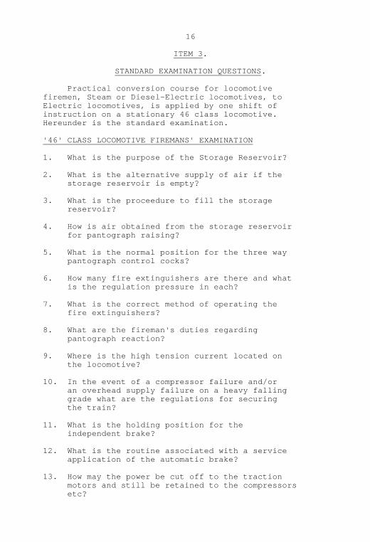
ITEM 3.
STANDARD EXAMINATION QUESTIONS.
Practical conversion course for locomotivefiremen, Steam or Diesel-Electric locomotives, toElectric locomotives, is applied by one shift ofinstruction on a stationary 46 class locomotive.Hereunder is the standard examination.
'46' CLASS LOCOMOTIVE FIREMANS' EXAMINATION
1. What is the purpose of the Storage Reservoir?
2. What is the alternative supply of air if the storage reservoir is empty?
3. What is the proceedure to fill the storage reservoir?
4. How is air obtained from the storage reservoir for pantograph raising?
5. What is the normal position for the three way pantograph control cocks?
6. How many fire extinguishers are there and what is the regulation pressure in each?
7. What is the correct method of operating the fire extinguishers?
8. What are the fireman's duties regarding pantograph reaction?
9. Where is the high tension current located on the locomotive?
10. In the event of a compressor failure and/or an overhead supply failure on a heavy falling grade what are the regulations for securing the train?
11. What is the holding position for the independent brake?
12. What is the routine associated with a service application of the automatic brake?
13. How may the power be cut off to the traction motors and still be retained to the compressors etc?


17
l4. Where are the Rheostats fan motors circuit breakers located?
15. How many of these circuit breakers are there and how may they be reset?
16. Where is the location of the low tension panels of miniature circuit breakers and which are the most important of these?
17. What is the correct order for M.U. Jumper Couplings and air hoses when coupling to another 46 class locomotive?
18. What are the fireman's duties regarding the grade control valves at Valley Heights on the Up journey?
19. State the fireman (a) preparation duties (b) stabling duties (c) road duties. (Including coupling and uncoupling of locomotives in Multiple Unit working).
..........
The foregoing examination represents thebasic standard requirement.
It is quite reasonably expected of firemen-observers employed on electric locomotives, that dueto opportunities now presented, they should progressivelyimprove their knowledge of the locomotive parts andfunctions and train working. To this end observationof the driver's activities and discussions with him isone very good method.
Locomotive Running Inspectors necessarily havean expert knowledge of all of the associated matter andfiremen-observers should never hesitate to take advantageof this source of instruction and information, whenpresent.
..........

18
ITEM 4.
ELECTRIC CURRENT. ITS ORIGIN AND USE.
Just as steam is the invisible agent to whichpressure is applied in order to drive a steam locomotiveso is current the invisible agent to which pressureis applied in order to drive an electric or diesel-electric locomotive.
Electric current is measured in amperes and agauge termed an ammeter is employed in electric circuitsto show just what volume of current is being fed to acircuit.
Before current may flow through a circuit twoconditions must always be provided, they are:
(a) A complete circuit or path must be provided fromthe source of supply, through a resistance and back tothe source of supply.
This source of supply takes the form of aGenerator or a Storage Battery.
(b) A pressure which is usually called Voltage orElectromotive Force, must be made available to pushthe current through the circuit.
A Voltmeter is a gauge which measures the voltageor pressure which is available to push current througha circuit.
Therefore, the higher the voltage available, thegreater is the amount of current which may be pushedthrough the circuit.
On a Diesel-Electric locomotive the Diesel Engineis used to drive a Generator of suitable size thusproviding the voltage or pressure necessary to pushcurrent via cables and contactors to the traction motors.
On an Electric locomotive voltage or pressure isobtained from the overhead wiring to push current viacables and contactors to the traction motors.
At the associated power houses, diesel engines,coal fired boilers and sometimes the force of fallingwater is used to drive Generators of suitable capacityand these prime-movers feed and maintain the voltage orpressure in the overhead wiring.

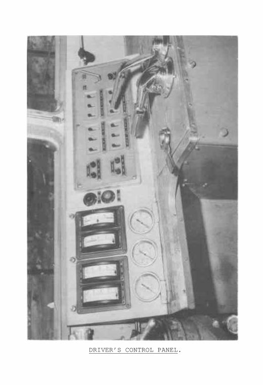
DRIVER’S CONTROL PANEL.
19
The voltage or pressure which is maintained inthe overhead wiring for the use by Electric locomotivesand Electric trains is maintained at about 1,500 volts.
Under certain circumstances this line voltage mayvary up or down by two or three hundred volts, but atall times it is regarded as High Voltage or High Tensioncurrent and great care is necessary to avoid the riskof human contact with it in that location or any connectionsto it within or about the locomotive.
Remember well also that most metals and an unbrokenjet of water will act as conductors of this current.
The following items are considered to be HighTension equipment:
The pantographs and connections and all roof rigging.
All equipment housed in both Nos. 1 and 2 High Tension compartments.
The voltmeters in each cab.
The motors which drive the four auxiliary machines and the associated cable connections.
The six traction motors and the cable connections.
All of this equipment is reasonably well secured against human contact.
To disconnect High Tension current from anylocomotive lower the pantographs and isolate them byclosing the respective isolating cocks.
If the pantograph cannot be lowered, use thehooked stick to open both pantograph switches.
It must never be assumed that any pantographhas moved in either direction without visual inspection.
.............

20
ITEM 5.
CIRCUITS. CIRCUIT BREAKERS, SWITCHES, FUSES.
An electrical circuit may be described as thepath through which current is caused to flow, togetherwith the source of supply of current flow, (usuallya generator or storage battery), the equipment beingoperated, the fuses which protect the circuit, and,the switches and circuit breakers which control thecurrent flow.
A closed circuit is a complete circuit where currentflows through the items described above.
An open circuit is a potential circuit as describedbut where due to some break in the total path,current cannot flow.
Since one of the essentials for current to flow isa complete circuit, the opening of a switch or circuitbreaker, or the burning out of a fuse, will cause anopen circuit.
A switch or circuit breaker may therefore bedescribed as an item employed to provide for the controlof current flow.
A fuse is a safety device placed in a circuitto protect that circuit from a harmful surge of current.
The action of a fuse is therefore to automaticallyopen the circuit and prevent further current flow, wherea harmfully high current surge is present.
With the cartridge type fuse a strip of conductingwire of some predetermined fusing value is used. Thus,where current surge appears, the fuse wire fuses or burns,thus becoming broken and disconnecting the circuit.
On a 46 class locomotive there are nine cartridgetype fuses employed in the various circuits.
In the auxiliary High Tension circuit there are: One 160 ampere fuse which protects the auxiliary circuit. one 50 ampere fuse which protects the supply generator motor. two 18 ampere fuses which respectively protect the two compressor motors. two 9.5 ampere fuses which protect the four voltmeters.
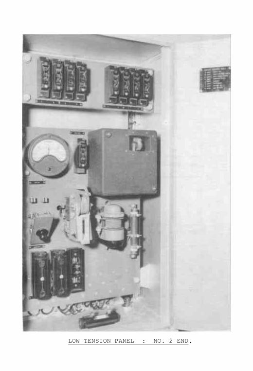
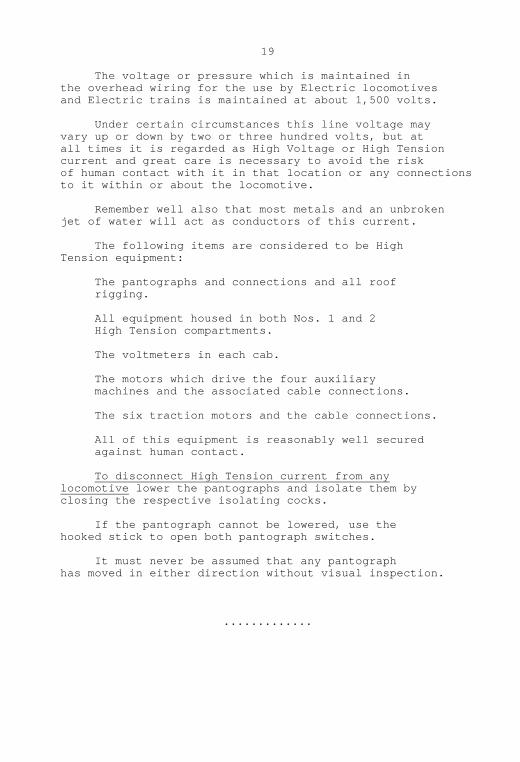
LOW TENSION PANEL : NO. 2 END.


FUSE TEST PANEL, SPARE FUSES AND MOTOR CUT-OUT SWITCH.

RESISTANCE FAN MOTOR MINIATURE CIRCUIT BREAKERSAND FAN TIME DELAY RESERVOIR.

21
In the low tension circuit there are three fuses,these are:
The 100 ampere Supply Generator fuse which protects the control circuit. The 100 ampere Battery positive fuse and the 100 ampere Battery negative fuse which protect the batteries.
Before any fuse in any circuit is handled for anyreason, including renewal, the corresponding circuitmust be isolated by opening the controlling circuitbreaker.
The very good reason for this precaution is thatwhilst a burnt out fuse has automatically disconnectedthe original circuit, contact with the hand may providea new and shorter path or circuit through the human body.
There is another protective device employed in lowtension circuits termed a thermal circuit breaker. Thisitem is a circuit breaker which has an inbuilt thermalstrip which reacts like a fuse in so far as that if aharmful current surge appears the thermal strip relaxesand trips the circuit breaker open, thus opening thecircuit.
Unlike the cartridge type fuse, renewal is notnecessary. Allow the thermal strip a short time tocool off, then reset the switch.
Never hold a thermal circuit breaker at the "on"position. This would defeat its purpose.
.............

22
ITEM 5.
MAGNETIC TYPE SWITCHES AND ELECTRO-PNEUMATIC TYPECONTACTORS.
These two devices, since they are basicallyswitches, are employed on the 46 class locomotive toconnect or disconnect or vary the route of currentflow.
As these are employed in the High Tensioncircuit, it is necessary that they be remotelycontrolled in the opening and closing actions.
Examples of the magnetic type switches arethe two contactors which apply and disconnect thehigh tension current feed to the two air compressormotors.
Examples of the Electro-pneumatic typecontactors are the six line switches and theStarting Resistance contactors.
All of these are necessarily housed in thehigh tension compartments of the locomotive.
Each of these types relies on the principleof a temporary magnet to close them and hold themclosed, and a spring which opens them when the tempo-rary magnetism is destroyed.
The closing of the contactor faces connectsthe high tension current, and the opening of thefaces disconnects the high tension current.
With the magnetic type switch, a Solenoidcoil is fixed to one of the arms of the contactor.
Control current (from the supply motor generatoror the storage batteries) is used to energise the coil,which now becomes magnetised and thus attracts andholds the second arm of the contactors.
With the electro-pneumatic type contactors,the Solenoid is used as a temporary magnet to controlthe passage of compressed air (Pantograph and ControlReservoir air) to a small air cylinder.


23
The piston in the cylinder is linked to amoving contactor arm.
The thrust of the air piston forces togetherand holds the contactor faces, thus permitting currentto flow.
When control current is switched off to theSolenoid, the magnetism disappears.
A spring reverses the control air valve, whichcuts off control air flow to the air piston and exhauststhe air from the air piston.
A spring now forces the air piston back and thecontactor faces are parted, thus cutting off the flowof high tension current.
In summary therefore, to operate either amagnetic type switch, or an electro-pneumatic con-tactor, to control the flow of high tension current,a low tension control circuit is necessary to operatethe solenoid coil.
Control current (120 volt) is supplied by thesupply motor generator or the nest of storage batteries.
To operate an electro-pneumatic contactor, inaddition to control current, to operate the Solenoid,control air pressure is required to operate the contactorair piston.
The electro-pneumatic arrangement is oftenreferred to as a magnet valve.
When the magnet valve is attached directly tothe high tension contactor, this is termed a Unit Switch.
Since the unit switches are housed together inhigh tension compartments of the locomotive, theyare referred to as Switch Groups.
The air cock termed the switch group isolatingcock is located on the supply pipe between the panto-graph and control reservoir and the switch groups, inthe machinery compartment.
.............

24
ITEM 6.
EMPLOYMENT OF HIGH TENSION (1500 VOLT) CURRENT ON '46'CLASS LOCOMOTIVES.
When the 1500 volt current is available (via thepantographs) within an electric locomotive ten hightension machines are required to be driven by such inorder that the locomotive may function in train haulage.
Six of these machines are called traction motors,four of these machines are called auxiliary machinesand are named as follows:
The Supply Motor Generator. The Exciter Motor Generator. No. 1 Air Compressor Motor. No. 2 Air Compressor Motor.
The six traction motors when driven by hightension current will each drive the locomotive axleto which it is connected and thus contribute to thetractive effort of the locomotive.
These traction motors are identified by beingnumbered. Running from the No. 1 end of the locomotivetraction motor No. 1 leads, with motors Nos. 2 and 3following on the No. 1 end bogie truck. No.4, 5, 6motors follow in that order on the No. 2 end bogietruck.
The current being fed to Nos. 1, 2, 3 motors isread on the Ammeter, second from the right at thedriver's station and the ammeter nearest the fireman-observer's station reads the current being fed tomotors 4, 5, 6.
In train haulage the current readings on bothammeters should agree, (except where one bank ofmotors has been isolated).
Any disagreement means that the armatures ofcertain motors are rotating faster than others andtherefore wheel slip is occurring.


25
The use of the Regenerative Brake on 46 classlocomotives employs the six traction motors toretard the locomotive and therefore the train. Duringthis process however, the traction motors are actingas six generators.
The conversion of an electric motor into agenerator is a simple matter requiring no alterationto the component parts, but merely some alterationto the current paths or circuits.
During this employment of the motors, thearmature ammeter, that meter at extreme right at thedriver's station, reads the amount of current nowbeing regenerated by all six motors if the SeriesCombination is being used. If the Series-ParallelCombination is being used then two banks of motorsare regenerating, and the armature ammeter currentshould be multiplied by two.
The current shown on the Field Ammeter, thatmeter second from the right reads the strength ofthe excitation current to the motor fields.
The Supply Motor Generator when driven by hightension current (at 1500 volts) produces-low tensioncurrent (at 120 volts) for purposes which will bedescribed under instructions dealing with the controlcircuit.
The Exciter Motor Generator when driven by hightension current (1500 volts) also produces low tensioncurrent separate from the former machine output, andthis current is used to drive the motors of eightresistances fans, and also to make it possible toconvert the six traction motors into generators. Eachof the two abovementioned machines also has attachedto the armature spindle a large blower fan, so thatwhen the machines run the two blowers run.
These blowers, called traction motor blowers,provide a large volume of air which is routed to thesix traction motor, thus assisting in cooling them andalso preventing any induction of metal filings, brakeshoe dust, etc.


26
When the motors of both No. 1 and No. 2 AirCompressors are driven by high tension current(1500 volts) air is induced, compressed, cooled andstored by the action of the respective compoundcompressors being so driven.
In summary the high tension circuit forks totwo different paths, first the main high tension cir-cuit which is directed through the traction motors,and secondly the auxiliary high tension circuit whichjunctions and branches away inside the locomotive, todrive the four auxiliary high tension machines. It isquite practicable to drive the four auxiliary machineswhilst not using the other fork of the high tensioncurrent to the traction motors.
This condition is necessary to take care of thecircumstances where the locomotive is standing orcoasting.
However, the main high tension circuit cannotbe used to drive the six traction motors unless theauxiliary high tension circuit is functioning, becausethis latter circuit provides a control system forcontrolling the former.
..............

27
ITEM 7.
THE CONTROL CIRCUIT.
The control circuit or low tension circuit on46 class locomotives at 120 volts is supplied andmaintained by the Supply Motor Generator.
A nest of storage batteries receives chargingfrom the Supply Motor Generator.
For a very limited period only the charge heldin the storage batteries will supply a control circuitand the only correct use of control current from thissource of supply is in the initial stage of enginepreparation and an emergency on the main line causedby failure of the supply motor generator, which cannotbe corrected.
Current from the abovementioned sources is usedby the driver to operate the pantographs, also a largegroup of contactors.
These contactors when operated either connect ordisconnect the high tension current to the ten hightension machines of the locomotive and vary the pathof such.
The storage batteries on 46 class locomotives haveonly limited storage capacity, therefore it is importantto get the supply motor generator running early in thepreparation routine and to keep it running during Trafficservice.
When the supply motor generator is running andproducing low tension current there is no demand onstorage battery current also battery charging is takingplace.
A continuous yellow lamp in the cab warns that thesupply motor generator is not running.
If the supply motor generator 100 amp. fuse fails,there is no output from that machine even though it isrunning and battery current automatically takes overand supplies the control circuit. This condition isindicated by a "discharge" indication on the ammeter andthe battery contactor will be open also the ExciterMotor Generator will stall.

LOW TENSION PANEL : NO. 2 END.

28
Additionally the cab heaters and food heaterswill fail.
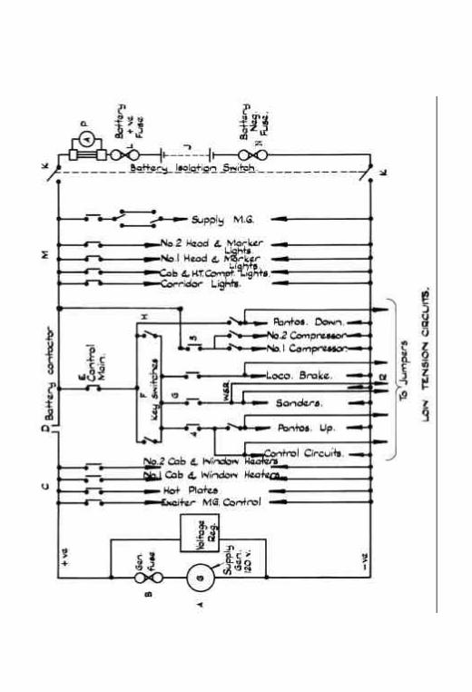
The included simplified Control Schematic diagramshould be studied and referred to, as required, toexplain the two sources of supply of control currentand the reaction to either source failing.
The Battery Contactor is the connecting ordividing point of each source of supply.
This contactor is closed automatically if thesupply generator is producing control current andopens automatically if no current is being suppliedby the supply generator. A device located in the lowtension cabinet controls the Battery contactor.
This device (not shown) is called the ReverseCurrent Relay, or Generator Automatic switch orBattery Relay.
If this device failed to open the Battery Con-tactor when no current was being produced by thesupply generator, then the Battery current would flowback through the Battery contactor and drive thegenerator as a motor and discharge the batteries inthe process.
...........

29
ITEM 7.
THE CONTROL CIRCUIT.EXPLANATORY NOTES ON SCHEMATIC.
"A": The Supply Motor Generator which produces current at 120 volts and feeds it through"B": Which is a 100 amp fuse on to the positive wire.
Control current is now routed through thatgroup of miniature circuit breakers marked "C".
Control current output through "B" willoperate a fitting (not shown) called the BatteryRelay or Reverse current Relay, or Generator Auto-matic Switch.
This Battery relay will in turn close theBattery contactor marked "D" and supply currentvia "E" to the desk control key "F".
Control key "F" will now feed current tothat group of miniature circuit breakers marked "G"and outside of the control key to that circuitbreaker "H".
As well as feeding through "E" and connectionsthe current is now available to that group of miniaturecircuit breakers marked "M".
With the Battery Double pole Switch "K" closed(connected) current feed is available via the 100 amperefuses marked "L" and "N" to charge a nest of storagebatteries marked "J".
The equipment marked "P" is the batteryammeter and this important device readily indicatesif the batteries are being charged or discharged.
With no output from the supply motor generator"A" the battery contactor "D" will open and the batter-ies "J" will provide for a limited time control circuitas far as (but not through) battery contactor "D".
With this limited time battery circuit it willbe seen on the simplified schematic all of the miniaturecircuit breakers marked "M" will be fed.

30
Unless the supply generator is producingcurrent that group of miniature circuit breakersmarked "C" cannot be fed.
With "E" closed and the supply generator "A"running, and producing current, and the batteries "J"connected through "K", group "E" and "H" are available.The control key must be in and on to feed that groupof circuit breakers marked "G".
The extended control lines marked "R" are thosewhich may be extended through the jumper couplers inM.U. working.
If the supply generator "A" or the 100 amperefuse "B" should fail, the reverse current relay willopen and disconnect the battery contactor "D".
The failure of fuses "L" or "N" would causea failure of the battery circuit.
The failure of fuses "B", "L" or "N" wouldcause battery charging to cease.
The Battery charging ammeter in the low tensioncabinet (No. 2 cab) should never show 'discharge', andthe Battery contactor should be closed.
If the ammeter shows 'discharge' and/or theBattery contactor is not closed, inform the driverimmediately. These indications show that Batterycharging is not occurring and that the locomotivemay be operated only for a limited period beforetotal failure of the control circuit.
..............

30A
Indication of depleted batteries on theselocomotives is usually by the dimness of the cab lightsand can often be detected during the preparation of thelocomotive. If the cab lights are not bright beforethe supply generator starts and the initial chargingrate is about 30 amperes this will indicate low batteries.
If the batteries are high the chargingshould be between 2 and 10 amps.
Where cab lights are observed as beingunduly dim when fed from the batteries alone and withthe supply motor generator now started up only a lowcharging rate is indicated on the battery ammeter thecondition of the battery is suspect and under thesecircumstances do not switch off the supply generatorbefore arrival at destination.
The battery ammeter is under all circum-stances the best indication of the condition of thebatteries and in some cases of very low batteries itis possible for a charge of 50 amps to be indicated,but this charge should not be maintained for more than10 minutes and in this period should fall to approxim-ately 10 amps. Should the charge rate be maintainedat 50 amps for over 10 minutes the battery double poleswitch should be opened and the batteries taken outof the charging circuit.
If an inspection of the battery contactoris made at any time do not lift the arc chute coveringthe contactor whilst the generator is running.
During the course of the preparation makean inspection of the battery ammeter with the generatorsrunning and compare the charge rate with the conditionsgiven previously. Before switching off a supplygenerator make another inspection and do not run thelocomotive with the generator switched off. Rememberthat if the batteries are depleted badly and the gener-ator switched off the locomotive will be a failure.
.........

31
ITEM 8.
PANTOGRAPHS AND PANTOGRAPH CONTROL.
The Pantograph provides the means of connectingthe overhead line voltage or disconnecting it from thelocomotive.
Raising or lowering of pantographs must never bedone whilst any current is being drawn.
Current is being drawn when either the throttle isopen or any of the four auxiliary high tension machinesare running.
During light engine running the rear pantographonly is to be employed.
During all train working both pantographs are tobe employed.
If only one pantograph is employed in train workingall of the machines may be adequately fed, but severesparking would take place if the current draw was heavy.
However, between Westmead and points East thereofwhere two or more locomotives are attached, only onepantograph is to be employed on each locomotive.
This exception is due to the lighter nature of theoverhead wire.
A yellow symbol with a black centre means stopand ascertain that the route intended is wired.
A Red Stop Board means stop and lower and isolateall pantographs if the 46 class locomotive is requiredto be hauled beyond that point.
Failure to observe these simple rules will causeserious damage to the pantographs.
Pantograph Raising and lowering reactions are tobe visually inspected by the fireman-observer, withreport to the driver.
Before entering a high tension compartment as wellas operating the lowering and isolating pantographmechanism, it is essential to observe that the panto-graphs have folded down. It is quite possible for thepantograph to remain in contact with the overhead wireafter lowering magnet valves have been operated, due tostiffness of the pantograph details.

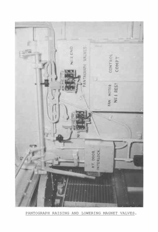
PANTOGRAPH RAISING AND LOWERING MAGNET VALVES.


32
To raise a pantograph it is necessary to have asupply of compressed air and to route it to thepantograph cylinder on the roof.
To lower a pantograph it is necessary to preventair flow to the roof cylinder and to discharge thatair already present.
These actions may be made by hand manipulation ofthe armature plate of the pantograph magnet valve, andthis method may be used when a fault exists in theraising or lowering buttons on the cab desk panel.
To raise pantographs by remote (cab desk buttons)control it is necessary that the control current ispresent through the control key, via the Battery switch.
To lower pantographs by remote (cab desk buttons)control it is not necessary to have the control keyswitched on, but Battery current must be switched on.
...........

33
ITEM 8.
PANTOGRAPHS AND PANTOGRAPH CONTROL.
There are two pantograph magnet valves.
Each magnet valve refers to the raising andlowering of one pantograph. (No. 1 end pantographand No. 2 end pantograph).
Each magnet valve, conforming to that des-cription contained in item 5, has two solenoid coilsinbuilt.
When the desk raising button switch ispressed, control current will flow to the raisingsolenoid. This solenoid now being a temporary magnetwill attract the vertical armature plate, which willthen allow the horizontal armature plate to fall down.
When this latter armature plate falls down,it permits an air valve to open and route pantographand control reservoir air pressure to the pantographroof cylinder.
The piston of the pantograph roof cylindernow forced out to full stroke releases a pawl whichpermits two raising springs to exert their force onthe pantograph, unfolding it and forcing it intocontact with the overhead high tension wire with aspring pressure of about 28 P.S.I.
When the desk lowering button switch ispressed, the raising solenoid is de-energised andthe lowering solenoid is energised.
The vertical raising armature is releasedthe horizontal lowering armature plate is attracted.
When the lowering armature plate is thusretracted, it engages the air valve, cuts off panto-graph and control reservoir air flow and dischargesthe air from the pantograph roof cylinder.
The pantograph lowering springs now takecharge and cause the pantograph to break away fromthe high tension overhead wire and fold down.
It is necessary to have control currentthrough the desk control key for pantograph raisingfrom the desk buttons.

34
The pantograph three-way control air cockmust be placed horizontal to route air from thepantograph and control reservoir to the pantographroof cylinder, and it must be placed vertically up-wards to route air from the storage reservoir oremergency hand pump.
In both cases, also the pantograph isolatingcocks should be open.
These are located immediately above themagnet valves.
If the desk button switches fail to energiseeither the raising or lowering solenoids of the magnetvalves, the armature plates may be hand operated.
Unless the high tension main switch is closedand locked with the Reverser Key, air cannot be routedto the pantograph roof cylinder, and any air containedin the roof cylinder is vented when the main hightension switch is unlocked.
In multiple unit working, the control currentwhich operates the pantographs on the front locomotive,also feeds through the jumper coupler to cause similaractions on the rear locomotive.
...............

35
ITEM 9.
AIR HOSES ON 46 CLASS LOCOMOTIVES, THEIR EMPLOYMENT ANDSPARE HOSE EQUIPMENT TO BE CARRIED. THE LOCATIONS OFAIR HOSES IN USE.
On the Driver's side of the locomotive at eachend a 1" head brake pipe end type air hose and dummycoupling.
On the Fireman's side at each end a 3/4" head mainreservoir and air hose and dummy coupler - Note - thesetwo (2) air hoses are not interchangeable.
On the Driver's side each end connecting betweencar body and bogie frame, one sand circuit intermediatetype air hose and one brake pipe intermediate air hose.
On the Fireman's side each end connecting betweencar body and bogie frame, one main reservoir, one brakecylinder, and one sand gear intermediate type air hose.
These intermediate type air hoses are referred to asflexible air hoses as they connect the two mobile portions,the car body and the bogie frames.
Two flexible air hoses on the roof of the 46 classlocomotives convey air for the operation of the panto-graph pistons.
Two 1/2" type 'B' air hoses which are used inMultiple Unit working to connect across the No. 3 andNo. 4 Independent brake pipes are carried when not inuse, in the corridor of No. 2 End of the Locomotive.
Spare hoses carried in the equipment box for waysidereplacement purposes are:-
One main reservoir end type air hose. One brake pipe end type air hose. One flexible intermediate type main reservoir air hose. One flexible intermediate type brake cylinder air hose. One intermediate type sand circuit air hose.
It should be always remembered that spare mainreservoir and brake pipe air hoses are convenientlylocated on the unconnected end of the locomotive.
No spare replacement flexible hoses for thepantographs are carried.

36
NOTES OF REPLACEMENT.
The two flexible air hoses on the roof may beseparately isolated, should they burst by closingthe applicable isolating cock in the machinery com-partment. The air pressure in the Pantograph andControl reservoir will readily indicate the isolatingof the defective hose.
It should not be overlooked that if the Pantographand Control Reservoir is greatly in excess of 70 P.S.I.,this excess pressure may be the cause of the burst hose.Should excess pressure be the cause of the burst hose,adjust the pressure in the pantograph and controlreservoir to 70 P.S.I. at the pressure reducing valve.
During train working if the flow meter indicatesa burst air hose:-
(a) First ascertain if the two intermediate and one end brake pipe hoses on the locomotive are not involved. (b) carry the correct spare hose and tool along the train until the burst hose is located. (d) where any interference with the brake pipe is necessary take special care that both relevant end air cocks have been fully opened.
.............

37
ITEM 10.
AUTOMATIC ALARMS AND SAFEGUARDS.
Under this heading there are four devices onthe '46' class locomotive.
These are:
(a) The Line Switch Indicator Lamp.
(b) The Motor Generators and Resistance Fans Lamp.
(c) The Wheel Slip Relay Buzzer and Lamp.
(d) The Westinghouse Brake Flow Meter and Indicator.
(a) The line switch lamp is the red lamp and it willflicker momentarily, as a normal function, when thethrottle is moved from "off" to notch one, if the lineswitches close and connect high tension current feed to thetraction motors.
Where due to a fault, one bank of motors has beenisolated, the line switch lamps will no longer be incircuit.
If, whilst the throttle is open, any fault developsin the high tension circuit, one of four protectiverelays will intervene and automatically open the lineswitches, on fault, (thus cutting off current flow to thetraction motors).
The red lamp will shine continuously to warn thedriver of the occurrence.
Since the line switches are of the electro-pneumatictype, a failure of the control current circuit, or thecontrol air pressure, would cause these to open on fault.
Again the red lamp would shine in warning.
When the Regenerative Brake lever is moved to thebraking field, the red lamp will shine, as an ordinaryevent, until the throttle is opened.


MAIN STARTING RESISTANCES.
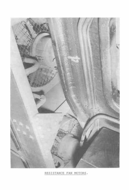
RESISTANCE FAN MOTORS.


RESISTANCE FAN MOTOR MINIATURE CIRCUIT BREAKERSAND FAN TIME DELAY RESERVOIR.

38
(b) The Motor Generators and Resistance Fans lamp isthe yellow lamp.
At all times when control current is availablethrough the Desk Control Key, if the supply motorgenerator is not running, the yellow lamp will shinecontinuously to warn the crew that neither the supplymotor generator, nor the exciter motor generator isrunning, and therefore, battery charging is not takingplace, that the battery charge is being bled away andthat traction motor blowing is not taking place.
When the throttle is opened and until it ispositioned at notch twenty (20), the high tensioncurrent flowing to the traction motors is being routedthrough all, or some, of the nineteen main startingresistances in order to graduate the starting effort.
These resistance units are housed in each hightension compartment immediately behind the fireman-observer's station.
These resistance units produce heat which afterone minute require forced ventilation.
Below each Resistance Compartment, four powerfulresistance (or Rheostat) fans are located.
Each has its own inbuilt motor.
One minute after the high tension current isfeeding through the resistances, these eight fan motorsshould start the fans running to ventilate the resistances.
If all, or any, of these fans fail to run and thethrottle has not reached notch 20, the yellow lamp willshine to warn the crew.
The principal causes of resistance fans failureare: Supply motor generator, (and exciter motor generator)not running.
Resistance fan Thermal Circuit Breakers tripped.
A simple and effective test for the resistancefans is to start up the supply motor generator, turnoff and then turn on the desk control key, and then placethe throttle in any resistance notch (1-19).

39
After one minute the yellow lamp will go outif all resistance fans have started up.
Some of the causes of Rheostat fan failuresare:
(1) Supply Motor Generator not running.
Supply Generator is running, but the 100 amp. fuse is burnt out.
The exciter motor generator supplies the currentwhich drives the fan motors, but the exciter motorgenerator will not run unless the supply motor generatoris running and producing current through the 100 amp.fuse.
An electro-pneumatic switch housed in themachinery compartment is used to connect current, ordisconnect it from the eight Rheostat fan motors.
A pressure of air at 60 P.S.I. is required toclose (connect) this switch.
The 60 P.S.I. air pressure is fed into the TimeDelay Reservoir for this purpose from the Pantographsand Control Reservoir. So that if the P. and C. Reservoiris isolated, or does not contain sufficient pressure, orthe Time Delay Reservoir is isolated, then the electro-pneumatic switch would not connect up the Rheostat fancurrent.
Housed in two separate cabinets in the machinerycompartment, are a total of eight thermal type circuitbreakers.
The current to drive the eight Rheostat fanmotors feeds in parallel through these.
If any one, or all, circuit breakers trip undercurrent load that, or those, Rheostat fans will stalland the yellow lamp will shine.
(c) The wheel slip relay equipped to 46 class loco-motives is for the purpose of warning the driver ofthe slip (in motoring) or slide (in Regenerative Braking)of any of the locomotive wheels.
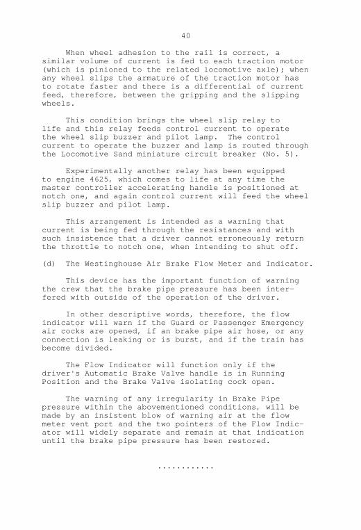
40
When wheel adhesion to the rail is correct, asimilar volume of current is fed to each traction motor(which is pinioned to the related locomotive axle); whenany wheel slips the armature of the traction motor hasto rotate faster and there is a differential of currentfeed, therefore, between the gripping and the slippingwheels.
This condition brings the wheel slip relay tolife and this relay feeds control current to operatethe wheel slip buzzer and pilot lamp. The controlcurrent to operate the buzzer and lamp is routed throughthe Locomotive Sand miniature circuit breaker (No. 5).
Experimentally another relay has been equippedto engine 4625, which comes to life at any time themaster controller accelerating handle is positioned atnotch one, and again control current will feed the wheelslip buzzer and pilot lamp.
This arrangement is intended as a warning thatcurrent is being fed through the resistances and withsuch insistence that a driver cannot erroneously returnthe throttle to notch one, when intending to shut off.
(d) The Westinghouse Air Brake Flow Meter and Indicator.
This device has the important function of warningthe crew that the brake pipe pressure has been inter-fered with outside of the operation of the driver.
In other descriptive words, therefore, the flowindicator will warn if the Guard or Passenger Emergencyair cocks are opened, if an brake pipe air hose, or anyconnection is leaking or is burst, and if the train hasbecome divided.
The Flow Indicator will function only if thedriver's Automatic Brake Valve handle is in RunningPosition and the Brake Valve isolating cock open.
The warning of any irregularity in Brake Pipepressure within the abovementioned conditions, will bemade by an insistent blow of warning air at the flowmeter vent port and the two pointers of the Flow Indic-ator will widely separate and remain at that indicationuntil the brake pipe pressure has been restored.
............


