a final report foundations for - nasa i of the foundations for ... a final report for year two of...
TRANSCRIPT
A Final Report
for Year Two of the Task
Methodology for Automating
Software Systems
Task I of the Foundations for
Automating Software Systems.
=--
Prepared for Tim Crumbley
NASA Marshall Space Flight Center
Redstone Arsenal, Alabama
by
Dr. Warren Moseley
University of Alabama in Huntsville
Research Institute Room M34C
Huntsville Alabama, 35899
(NASA-CR-184233)
SOFTWARE SYSTEMS
Univ.) 96 p
METHODOLOGY
Final Report
FOR AUTOMATING
(Alabama
CSCL 09B
G3/61
N92-I0301
Unclas
0287445
https://ntrs.nasa.gov/search.jsp?R=19920001083 2018-06-03T22:51:31+00:00Z
r_
w
A Final Report
for Year Two of the Task
Methodology for Automating
Software Systems
J
Task I of the Foundations for
Automating Software Systems.
w
Prepared for Tim Crumbley
NASA Marshall Space Flight Center
Redstone Arsenal, Alabama
by
Dr. Warren Moseley
University of Alabama in Huntsville
Research Institute Room M34C
Huntsville Alabama, 35899
F
Introduction
m
This report will consist of four parts.
Section I - Software Assessments for Government Contractors
Section II - The Poor Man's Case Tool at age Two
= = Section III - Requirements Traceability using Expert Systems Tools
Section IV - Theoretical Foundations of the Poor Man's Case Tool
w
L_
n
SECTION I
SOFTWARE ASSESSMENTS
FOR GOVERNMENT CONTRACTORS
Software Assessments for Government Contractors.
On December 9,1989, Dr. Carl Davis, Dr. Ashok Amin, Dr Jim
Hooper, and Dr. Warren Moseley attended the briefing for the Software
Assessment Program at the Software Engineering Institute - Carnegie-
Mellon University in Pittsburgh Pennsylvania. We were introduced to
the SEI work on Software Process Modelling and the emphasis on the
software assessment model The first section of this report focuses on
two areas of this assessment. These two areas are:
1. Software Process Modelling,
2. The Software Assessment Criteria.
Software Process Modelling and the Software Assessment
2
w
m
L ,
m
w
w
L •
m,
i
w
w
Software Engineering Institute, SEI, located in Pittsburgh,
Pennsylvania, is a federal funded research and development center
operated by Carnegie-Mellon University, under contract to the
Department of Defense. An SEI objective is to provide leadership in
software engineering and in the transition of new software engineering
technology into practice.
In this paper we will discuss the software process modeling and
the impact of software process modeling on the functional capabilities
of the software engineering group at Building 4487 at NASA/Marshall
Space Flight Center. The purpose of the method for assessing the
software engineering capability of contractors was to facilitate
objective and consistent assessments of the ability of potential
Department of Defense(DoD) contractors to develop software in
accordance with modern software engineering methods. Such
assessment would be conducted either in the presolicitation
qualifications process, in the formal for proposal selection process or
perhaps in both. This document is intended to guide the assessment of
the contractors overall software engineering capability. It can be also
valuable in the assessment of a specific project team's software
engineering capability. This document can also be used as an aid to the
software development organizations in conducting internal
assessments of their own software answering capability. The helps
and suggestions in this document are designed to be a help in an
assessment teams to finding the highest priority for improvement of
the organization's capability A well-defined software process is
needed to provide organizations with a consistent framework for
performing their work and improving the way they do their work. An
3
m
w
overall framework for modeling simplifies the task of producing
process models, permits these models to be tailored to individual
needs, and facilitates process evolution.
Considerable attention has been devoted to software process
modeling during the past few years. In the Poor Man's Case Tool which
was developed under the direction of the software engineering group at
NASA, the concept of process modeling has been an integrated overall
part of the entire computer assisted effort for software engineering in
this particular contract. Models of the software life cycle processes
are expected to provide a means for reasoning about the organizational
processes used to develop and maintain software. Most efforts in this
field have focused on the functional or task oriented aspects of the
process.although a few recent efforts have proposed behaviorally
oriented modeling approaches. Even these however still approach
behavioral modeling from a task oriented standpoint. Several people
work cooperatively on a common project. They need someway to
coordinate their work. For relatively small or simple tasks this can
often be done informally, but with larger numbers of people or for more
sophisticated activities, more formal arrangements are needed.
For example, process definition can be compared to football
training. Teams without defined and practice plays do not make the
play-offs. Or the sequence of plays will change from game to game,
The winning team generally has worked out the plays in advance, knows
when to use them, and can perform them with skill. The software
process is much the same. Unfortunately, a few software teams work
out their plays in advance, even though they know the key problems
they will encounter. For some reason they act as if late requirements
4
w
r
Lmw
w
L
changes, regressions, or system integrations problem will never occur.
The software process is a technology and managerial framework
established for applying tools, methods, and people to the task of
creating quality software. A defined process not only prepares for
likely eventualities, it also provides a mechanism for organized
learning.
As projects improve their methods for handling key tasks, these
can be incorporated in the repertoire of plays available to the rest of
the organization. This process definition makes it easy for each new
project to build on the experience of its predecessors, and also
protects against the dangers of ill-prepared crisis reactions.
An important observation of process management is that
process changes adopted in a crisis are often generally misguided.
Crisis are the times when shortcut are most likely when organizations
are most prone to omit critical tasks. These shortcuts often lead to
truncated testing, missed inspections, and deferred documentation.
With time at a premium, rationalization is most likely and process
judgements are least reliable. Because it is difficult to justify many
tests, analysis or inspections in the heat of the moment, a thoughtfully
defined and approved process can be a great help. When the crisis
occurs, it has been anticipated and established means are at hand to
deal with the crisis situation. In short, a defined process provides the
software professional with the framework they need to do a
consistently professional job.
While there are often needs for project specific process
tailoring, there is also a compelling reason for a standard process
framework:
5
=--
w
E
u
w
z,
v
z
m
w
1) Process standardization is required to permit training,
management review , and tool support. With standard
methods, project experience can contribute to the overall
process improvement in the organization. Process standards
provide a structured basis for measurement because process
definitions take time and effort to produce. It is
impractical to produce a new one for each project because
the basic tasks are common to most software engineering
projects. A standard process framework will need only
modest customization to meet most special project needs.
A software process architecture is the framework within
which a projects specific software processes are defined.
It establishes a structure, the standards, the relationships
of the various process elements. Within such an
architectural framework, it is possible to define many
specific processes. A software process model is then one
specific embodiment of such a software process
architecture. While software process models may be
constructed at an appropriate level of abstraction, the
process architecture must provide the elements, standards
and structural framework for refinements to any desired
level of detail. The criteria for effective process models:
Before establishing criteria for a evaluating process model
approaches, it is first necessary to define the uses of such
models. The basic uses for process models are:
1) Enable effective communication regarding the process. This
could involve communication among process users, process
6
_m
h
w
m
w
w
m
m
developers, managers, or researchers. It enhances
understanding, provides a precise basis for process
execution and automation, and facilities personal mobility.
2) Facilitates process reuse. Process development is time
consuming and expense Few projects can afford the time or
resources to totally develop their own software processes.
3) Supports process evolution Precise easily understood,
expandable, and reusable process definitions provide an
effective means for process learning. Good process models
are thus an important element of software process
improvement.
4) Facilitate process management: Effective management
requires a clear understanding of plans and the ability to
precisely characterize status against these plans. Process
models potentially provide a framework for precisely
defining process, status, criteria, and measurements.
From the above it should be clear that process models must
provide the following capabilities:
a) They should represent the way work is actually done or
actually to be done in the organization.
b) Provide a flexible and easily understandable yet powerful
framework for representing and enhancing the process and
c) Be refineable to what ever level of detail is necessary.
The first two points are relatively obvious, but the third one is
often overlooked. As improvements are made in supporting the
software process, precise task definitions are required to permit
effective tools and environment development. As with any data
7
u
w
=
m
L_
w
F -
m
processing application, poorly understood tasks lead to inadequate
requirements in ineffective systems. What is more challenging than
most application developments, software process automation is much
like application development and thus must start on precise process
models at relatively deep levels of detail.
Finally, to be most effective in supporting
process modeling, process models must go beyond
the four
representation.
must support comprehensive analysis of the process through the
and allow predictions to be made regarding the consequences of
objectives of
They
model,
potential changes and improvements. Certainly, modeling approaches
that smoothly integrate representation, analysis, and predictions are
preferred t23
A number of process models have been proposed in the literature,
including the Waterfall Model 45. and the Spiral Model s. While these
models has been helpful in explaining the software development
process, they has several shortcomings with respect to the above
criteria.
11) Mark I Kellner, Representation Formalism For Software Process Modeling, Proceedings of the 4thInternational Software Process Workshop, Representing and Enacting the Software Process, ACM1988, Pages 43 - 46.22) Mark I Kellner and Gregg A Hanson, Software Process Modeling, Technical Report, CMU/SEI-88-TR-9, Software Engineering Institute, Carngie-Mellon University, May 1988.,33) Mark I Kellner and Gregg A. Hanson, Software Process Modleing, "A Case Study", Proceedings ofthe 22nd Annual Hawaii International Conference On Systems Sciences, Vol. II, Software Track, IEEE,1989, pages 175-188.
4Royce, W., Managing The Development of Large Software Systems, Concepts andTechniques,Proceedings of the IEEE Westcon ??,IEEE, August 1970, Pages 1-9.5Royce, W., Managing The Development of Large Software Systems,Proceedings of the 9thInternational Conference on Software Englneering,lEEE 1987, Pages 328-338.
6Barry W. Boehm, A Spiral Model of Software Development and Enhancement,ACM SoftwareEngineering Notes,No. 11, Vol. 4.,August 1986, Pages 14-24.
8
r .
h
m
!
Rm
1) They do not adequately address the evasiveness of changes in
the software development.
2) They unrealistically imply a relative uniform orderly
sequence of development activities.
3.) The do not easily accommodate such recent developments as
rapid prototype or advanced languages.
4) They provides insufficient details to support process
optimization.
The overall reliance on the Waterfall Model has had several
uniform unfortunate consequences. First, by describing the process as
a sequence to requirements, design, implementation, and tests, each
step is viewed as completed before the next one starts. The reality is
that requirements live throughout the development and must be
constantly updated. Design, code and test undergo a similar evolution.
The problem is that when managers believe this unreal process, they
require that designs, for example, be completed before implementation
starts.
Everybody who has ever developed much software knows that
there are many tradeoffs between design and implementation. When
the design is not impacted by implementation, it means that either the
design went too far or the process was too rigid to recognize and
adjust implementation problems. The design and its documentation
must evolve in concert with the implementations. Unrealistic
software process models also bias the planning and management
system. When requirements are suppose to be found before design
9
._=..
w
B
starts, various documents and reviews are conducted to demonstrate
requirements completion. Since these documents must also change as
design issues are exposed, the status view of requirements can be
counter productive. Fuel is added to the fire by pressure from
management with an early freeze on changes. This inhibits creative
design requirements tradeoffs just when they should be encouraged.
These problems have corresponding analogs in design implementation,
and tests. The final consequence is process measurement. When an
unrealistic process model is used as a basis for planning, the
measurement and tracking system is corrupted. Since resources or
lead times standards are corrupted by the lack of clear activity
boundaries planning and tracking are equally imprecise
The fundamental problem with the current software process
models is that they do not accurately represent the behavioral or
timing aspects of what is really done. The reason is that traditional
process models are extremely sensitive task sequences. Consequently,
simple adjustments can require a complete restructuring of the model.
Rather than making an arbitrary decision such issues should be referred
to a systems design group for resolution.
The Software Assessment Criteria.
It should be pointed out in the consideration for a software assessment that
the results of the software assessment are confidential, and they are to be used
initially as a means of assessing the current situation of the organization.
a_=J=
10
't=_=
w
w
Section II
The Poor Man's Case Tool
at Two Years OId.lh General Introduction and Background for
The Poor Man's Case Tool(PMCT).Research Platform CASE
Environment.
The University of Alabama in Huntsville is in the third year of a
five-year intensive research program to establish a experimental
research platform for software engineering. There will be a major
emphasis placed on CASE and the importance of CASE to the
improvement of the practice of software engineering. This project is a
first step in establishing this research program, and first in a part of
this three year effort here at NASA.
Outline of major functions of our case tool
The operation of this system, Poor Man's CASE Tool, is based on
the Apple Macintosh system, employing available software including:
Focal Point II, Hypercard, XRefText, an existing Expert
System Tool and Sidekick These programs are functional in
themselves, but through advanced linking are available for operation
from within the tool under development.
The software industry is in need of maps, a plan where they want
to go, how they want to get there and something to measure their
progress as they journey. They need CASE tools. As hardware
technology advances are reported on a daily basis, true software
advances are much fewer and farther between. The technology required
to dramatically increase the processing speed of a computer produces
very visible and objective results, but software improvements are
often subjective and very tenuous. Today the focus on software is no
11
w
m
E
w
m
m
IB
longer entirely aimed at getting the job done, but, due to the rising
cost of maintaining and developing software, rather, to make the
process of arriving at the solution more efficient. Since applicable
software theory is limited to the confines of the hardware and
operating systems available, and major breakthroughs are rarely
imminent, the only solution to this "software crisis" is some form of
software production engineering. This methodology would allow
software to be synthesized instead of "written" or even "built."
Computer Aided Software Engineering, CASE, is a tool well suited
to this concept. Software development has already gone through enough
phases to allow for reuse of design at the concept or even the code
level. Such is the aim of the Department of Defense mandating that all
new software systems be written in a standardized and certified Ada
system. Thereby a new portability can be found in one of the largest
software development arenas in the world. This mandate also implies
some operation requirements on the hardware to be used. What has
then been ordained is an ability to employ "technology transfer" across
development lines. This allows for information and ideas to be reused,
since, in the present economy, it is far cheaper to use something that
has already been done, than it is to prepare a customized system.
While the tendency used to be that a customer would require a system
to do the job just as he did it on paper, or by hand, today's customers
are more ready to accept something that works already and make some
modification to the process to be performed, whether it involves
simply using a new form or a new procedure. The task is not to get the
old job done, but to produce better results more efficiently.
w
i
12
m
m
m
The state of the software world is still predominantly made up of
custom built software systems, but as more modular languages, such
as Pascal, C and Ada, and operating systems, such as UNIX and UNIX
derivatives, come into play, generic function code segments no longer
need to be rewritten. The programmer need only pool his resources
with those of others and find a routine that already performs the
required function. Fortunately, the availability of these routines and
access to them is steadily increasing through the use of Local Area
Networks, Bulletin Boards, software libraries and software
warehouses. All of these facilities encourage sharing software and are
being relied upon more and more to cut down on development time.
Although much is being done about this problem, it still remains. There
are only so many concept changes than can be effected in the current
software development and use arenas, since there is such a large
distribution of effort and users in the field.
Standards, wisely chosen and stringently implemented, will help
to set the pace, but the volatility of the computer industry itself does
not lend itself to a lot of trust in committing to a specific system.
Today, standards are more widespread, but changes are still rapid, and
necessary. As standards approach the concept and implementation
level, that is beyond specific coding routines and methodologies, real,
functional, progressive systems can be implemented at many levels of
service.
The term 'CASE TOOL' refers to a computer system tool which
provides the capability to perform software system design, i.e..
Computer-Assisted-Software-Engineering. The approach represents
the problem solving process at an extremely high level of abstraction.
13
'lr._=, o
w
m
!
m
E
w
I feel this is important since often the software engineering process
relies specifically on an outline of the complete problem domain. After
all, if the engineer cannot see 'the big picture' how can he be expected
to know exactly where the smaller entities and procedures should be
integrated. The development of CASE tools has been fairly recently
introduced into the software development community and has been met
with a tremendous amount of enthusiasm. The functionality of a CASE
tool is based upon the general structure of the software life-cycle and
is built to allow a general specification for each phase of the software
engineering process. This capability provides a flexibility that cannot
be found with other software design tools. From the specification /
requirements phase where data dictionaries / entity relationships are
constructed, to the maintenance phase where the system design can be
restructured, the CASE environment provides a variety of tools to aid
in the construction of system software.
I!. CASE Needs
The fact that CASE tools are in great demand is partially due to
the change in software needs: programs should be efficient, easily
maintained and modifiable, and are usually quite large. The size of
programs especially calls for an efficient organizational tool for the
software engineering process. Many times, the design process is
documented on blackboards, and some even reside completely inside
one software engineer's mind. This causes an extremely difficult
problem for the implementation of large systems when many
programmers are needed to complete the task. Also, the diverse
methods used by some designers do not allow for easy access to
program sections by other persons of the software development team.
14
= _
=__
The use of CASE tools, however, provides a means in which the entire
task ( be it large or small ) can be assigned to any number of designers
on the team. This capability allows documentation to be constructed
while the system is being constructed. Therefore, the integration of
the entire system and changes to the design can both be performed
easily. Not only documentation, but when one member of the team finds
a need to access information from another team member, that
information can be accessed immediately from the same environment.
This has a psychological impact, in fact, when each member feels like
'part of the whole', the system design process will be more expediently
performed.
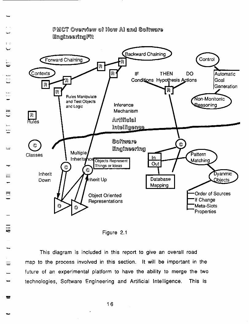
Artificial Intelligence and Software Engineering
The following diagram illustrates the relationship of Artificial
Intelligence and Software Engineering and how some of the components
fit into an overall scheme of problem solving.
mw
15
= =
w
=
v
_rward Chainin_
Backward Chaining
IF THEN
Condil is
Rules Manipulate
and Test Objects
and LogicInference
Mechanism
®Classes
Inherit
Down
MultipleInh_
Objects Represent
Things or Ideas
UpI Database IMapping
Object OrientedRepresentations
DO
Qi utOmatic
oaleneration
Order of Sources
If Change
Meta-SlotsProperties
=
Figure 2.1
This diagram is included in this report to give an overall road
map to the process involved in this section. It will be important in the
future of an experimental platform to have the ability to merge the two
technologies, Software Engineering and Artificial Intelligence. This is
Ii
16
= _
w
w
an important factor. In the first prototype of the PMCT the sections of
Artificial Intelligence(AI) are not included. It is important to
understand that phase one of the task Methodology for Automating
Software Systems includes the establishment of the overall framework
for the inclusion of all of the components.
Since the original prototype of MASS was done on the Macintosh,
primarily in Hypercard, the ability to launch application gives NASA the
ability to invoke Clips from any point in the process. Dan Rochowiak in
his task, which is a part of the overall UAH task, shows a
demonstration of how Clips can be used in the context of a Hypercard
application. This concept will be explored in more detail in phase !1
and phase II1.
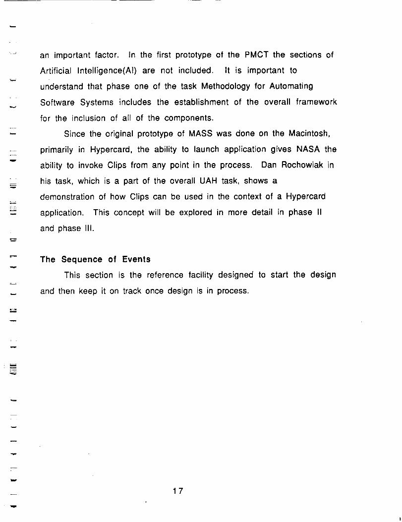
The Sequence of Events
This section is the reference facility designed to start the design
and then keep it on track once design is in process.
m
w
17
m
m
B
w
m
_I
First
nments
Figure 2.2
The original proposal is entered into this section and it is
modified only as the customer deems necessary, beyond this, it is only
used as a reference tool to keep the project in line with the customer
demands.
The Tool also includes work planning tools, including facilities to
generate PERT charts and COCOMO cost estimating models. These tools
are industry standard job tracking references, allowing new users with
project control experience to use the system without having to learn
new methods of project tracking.
Another portion of the tool maintains the project database.
Functions of this portion include specification generation and analysis.
These segments are generated at the inception of the project and serve
as benchmarks for the design process. The Data Dictionary support
environment is maintained through the use of Hypercard and facilitates
=
18
r
L_
L .
r _
w
E
w
L_
m
m
w
mw
quick paging through data samples and formats. This section is
directly accessible through the Tool's main menu. The Screen Painter
serves as a user interface to the Data Dictionary. Using Focal Point II,
it allows the user to create data entry and query forms to be used
against the dictionary. Implementation support is a repository of
functions to control and maintain system software design. The
functionality of this would also include traceability of software
modifications and other configuration management functions, such as
binary library maintenance. This portion also includes the DOD
standard specifications for software development, and a reusability
subsystem, to prevent duplicate effort on the same project.
Tool Integration is the Focal Point.
One of the main objectives of the Poor Man's Case Tool was to
provide access to a variety of tools for an integrated software
development environment. The idea that a system should be visually
intuitive is the focus of this project. From this point the user can get
to any portion of the Case tool that is needed. One of the important
parts of this tool is the Project Monitoring function.It does not appear
on the main card or anywhere in the utilization of the tool. One of the
ideas for this project was to try to derive from simple work pattern
study techniques the sequence of events and underlying patterns that
are an integral part of the software engineering process.The project
monitoring function is totally transparent to the engineer that is using
the tool.This places no burden on the engineer in the data collection
process.From studying the patterns, further research will be conducted
to help derive the conceptual structures that are a part of the thought
process that goes into the design of software products.
19
v
F_
I
D
There are several major functions contained in our CASE tool,
built for NASA, they include capabilities to perform the following
tasks"
Planning and MonitoringStatement of Work
Automated Status ReportsCost Estimation
Expert Systems Projects
Conventional Software Projects
Project Data Base Construction Tools
Flexible Drawing Tool
Included Drawing Tools
Links to existing Drawing Tools
Data Dictionary
Implementation InterfaceCompiler Support
Configuration Management Support
Complete Automated Traceability Support
m
=
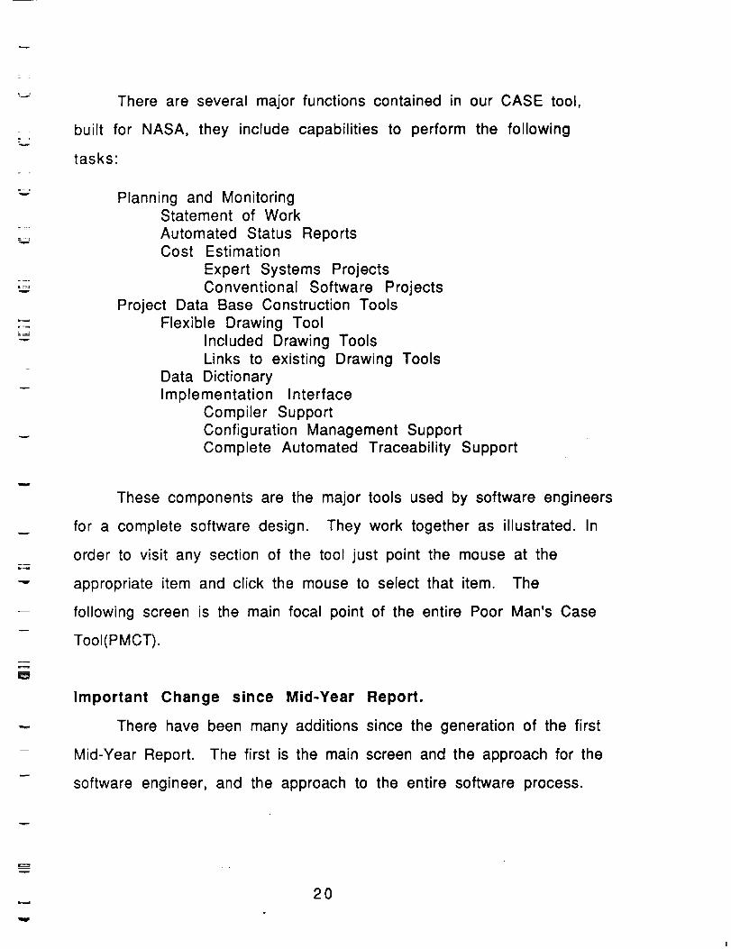
These components are the major tools used by software engineers
for a complete software design. They work together as illustrated. In
order to visit any section of the tool just point the mouse at the
appropriate item and click the mouse to select that item. The
following screen is the main focal point of the entire Poor Man's Case
TooI(PMCT).
Important Change since Mid-Year Report.
There have been many additions since the generation of the first
Mid-Year Report. The first is the main screen and the approach for the
software engineer, and the approach to the entire software process.
20
=.__.7
W
'==wr
Me Dow
-' I°Iooooooooo I "|I_0000000 I
I_°°°°°_ I L_
E
=v
Figure 2.3
With the pull down menu in the above screen, the user has
options not before available. This Menu looks like the following.
Pull Me Down
Process
Plan
Repository
Help
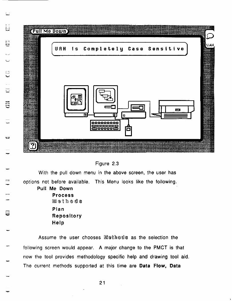
Assume the user chooses __]_ as the selection the
following screen would appear. A major change to the PMCT is that
now the tool provides methodology specific help and drawing tool aid.
The current methods supported at this time are Data Flow, Data
m
m
21
==
_m
Structured(Warnler-Orr),I
and Entity Relationship approach.
Help Is always available
You can also et back to Process
Figure 2.4
in addition there is also the addition of process. A CASE tool will
not provide the desired result unless it is based on an adequate
software process model. The Current models available are IEEE,
2167a, and the NASA Management Standard.
22
r
w
I7 A Software Development ProcessB
i=_==I - Software Development=__ _[ _II I I SRR Ap pro_,411_ II
Ioustome'rI k I [- SS.Appro__ProjMg_l
_ I' (Requir_ementsStage) F-_DesignStageJ-cDRXPP_'I_PD_PP_I_ -II
_.i_ ' _' I _T _--_'
I IC'oo'e°entatio."ao Test and Evaluation Stage)Audits
r'
IIso_eProject Library
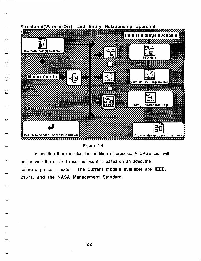
Figure 2.5
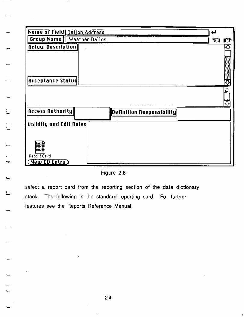
One of the salient features that has been
added to the PMCT since the mid-year is the inclusion of a simple
report generator. It was decided to use the package REPORTS from
Activision for the prototype, since it works easily with the existing
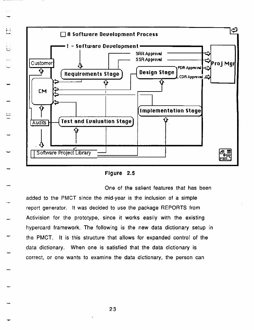
hypercard framework. The following is the new data dictionary setup in
the PMCT. It is this structure that allows for expanded control of the
data dictionary. When one is satisfied that the data dictionary is
correct, or one wants to examine the data dictionary, the person can
23
w
Name of FieldlBallon Address
IGroup Name IIWeather Ballon
Actual Description
Acceptance Statu_
£i
iO
Access Authorityl
Validity and Edit Rules
IIDefinition Responsibilityll
Report Card
(New DD Entru_}
Figure 2.6
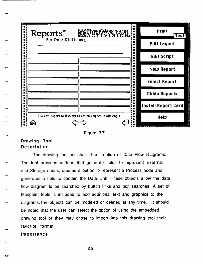
select a report card from the reporting section of the data dictionary
stack. The following is the standard reporting card. For further
features see the Reports Reference Manual.
24
w
i :ioi
Reports TM wzHmRwm ,.rRoM_]ACTIVI SION®
For Data Dictionary
IIIIIIII
(To edit report button press option key while clicking.)
<h<>
Edit Layout
Edit Script
New Report
Select Report
Chain Reports
li"• o Install Report Cardli"!: Help
<p.i!
Figure 2.7
Drawing Tool
Description
The drawing tool assists in the creation of Data Flow Diagrams.
The tool provides buttons that generate fields to represent External
and Storage nodes, creates a button to represent a Process node and
generates a field to contain the Data Link. These objects allow the data
flow diagram to be searched by button links and text searches. A set of
Macpaint tools is included to add additional text and graphics to the
diagrams.The objects can be modified or deleted at any time. It should
be noted that the user can select the option of using the embedded
drawing tool or they may chose to import into this drawing tool their
favorite format.
Importance
25
=
w
I
_= ='.
The drawing tool provides a map into the design of the project.
This map is a high level plan toward achieving the project goal,
describing the flow of data and the relationship among components.The
drawing tool is the map that guides the creation of the other maps
within the CASE tool.
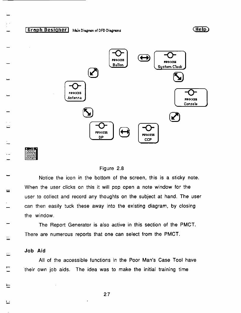
Sample Example
The following will be a sample of the types of screens that will
be available from the drawing tool. The first is the main card. The
entire drawing tool is completely flexible to support many types of
applications, it will make available through selective buttons the
ability to create and modify standard shapes, such as oval, square etc.
The user can just point the mouse at the buttons and click to create
that shape.
E-=
i
w
m
26
w
u I Graph Desiqnerl M_nDi_mofDFDDie_ms
u
._J
m
i
m
r •
W
P_OCC§§
Antenna
Pi_OCCSS
Ballon •System Clock
-O-f ,,o,., I
Figure 2.8
Notice the icon in the bottom of the screen, this is a sticky note.
When the user clicks on this it will pop open a note window for the
user to collect and record any thoughts on the subject at hand. The user
can then easily tuck these away into the existing diagram, by closing
the window.
The Report Generator is also active in this section of the PMCT.
There are numerous reports that one can select from the PMCT.
Job Aid
All of the accessible functions in the Poor Man's Case Tool have
their own job aids. The idea was to make the initial training time
m
27
m
I
i
i
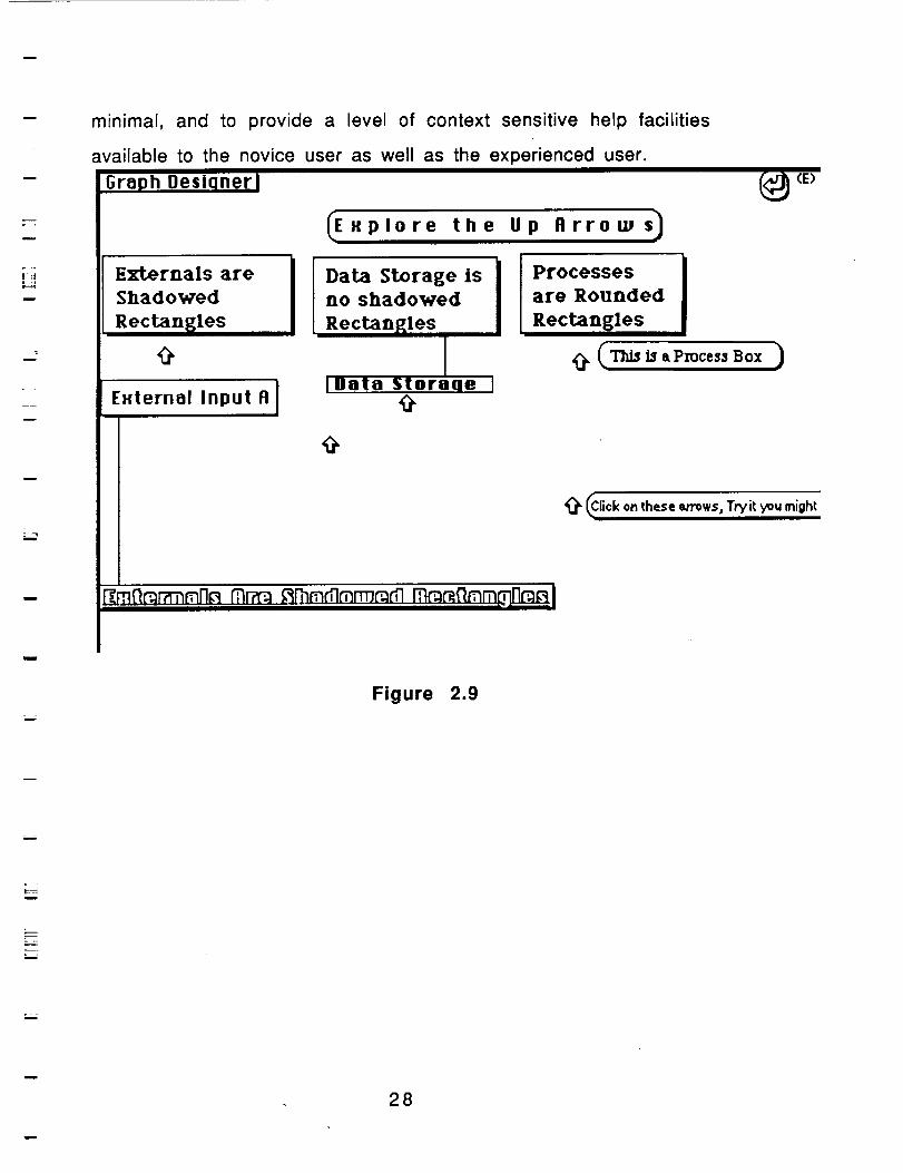
minimal, and to provide a level of context sensitive help facilities
available to the novice user as well as the experienced user.
h Desi(
Externals are
Shadowed
Rectangles
External Input A I
I I°a_s_rage'sI IPr°c°s°esIno shadowed are Rounded
Rectangles Rectangles
I _ (This is aProcess Box )
IData Storaqe I
@
(E)
(Click on these ='rows, Tryit you might
Figure 2.9
m
28
=-,..
i
m
Data Dictionary Support Environment
Data Dictionary
Description
In PMCT the data dictionary is directly linked to the drawing and
vice versa. It is important and mandatory to establish this link
between graph and dictionary. The data dictionary is a storehouse of
information for data fields. The data dictionary is responsible for
describing many aspects of the total system.The data dictionary
includes many cross references between data elements and program
modules. The cross references also include modules, the reports they
generate, and the variables used in them. The information that the
dictionary contains is broken down into three parts.
The sections of the PMCT
u
i
===
1. Start up procedures
a. Who is doing the project
b. Scope of Project
c. Project Startd. Scheduled Completion
e o Why is the project being done
f o Who says what the project will
encompassg. Who is going to pay for the project
w
•
el
f.
g.individual
Personnel
a. Group Nameb. The Database Administrator
c. Individual member of the group
d. The individuals job title
The company that the individual works for
The address of the company
Phone numbers for contacting the
i
i
29
m
u
m
u
g Variables and Data
a. Project IDb Group Name doing the project.C. Variable name
d. Variable length and range
e. Variable typef, Modules accessed
g. Reports generated
h. Module Creation and Update
Importance:
The importance of the data dictionary is to limit the confusion
ti ._t occurs during major programming tasks. The standards are set up
in the data dictionary that the project will use. The data dictionary
allows everyone access to the standard format of the data and the
standard usage of the data. In this respect the data dictionary directly
supports software development and maintenance.
The next information is the personnel assigned to the project and
the information pertinent to each of those personnel. Notice that the
Job Aids are always accessible from any place.
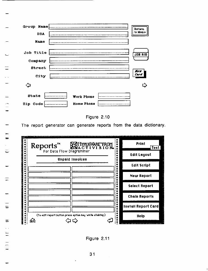
Put in new Data Dictionary Form
w
w
w
w
w
30
oro_ .-,-t ......................................................................................................
co=p=_ I................................................................................................t8_ree_t......................................................................................................-Ioily I-.............................................................................................I
0
.o,kPho.°I............................................IHome Phone
Returnto Menu
0
w
iw
w
Figure 2.10
The report generator can generate reports from the data dictionary.
IIII-
Edit Layout
Edit Script
New Report
Select Report
Chain Reports
Install Report Card
Xelp
Figure 2.11
31
w
i
m__
w
i
L--
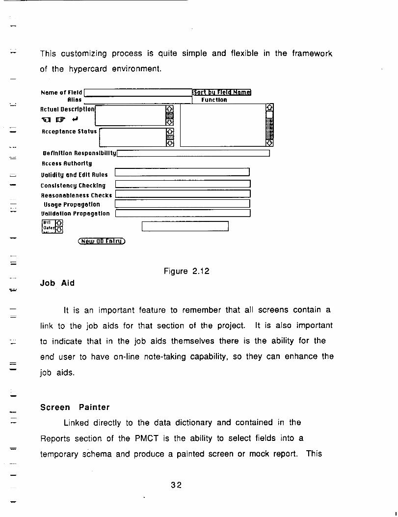
This customizing process is quite simple and flexible in the framework
of the hypercard environment.
Name of Field [!
Alias
Actual Description
Acceptance Status I
Definition Responsibility I
Access Authority
Validity and Edit Rules I
Consistency Checking [
Reasonableness Checks I
Usage Propagation I
Valldatlon Propagation I
Sort bu le!d Name
"_ function
[]@
I
[ ICNew DD Entru)
Job Aid
Figure 2.12
m
w
It is an important feature to remember that all screens contain a
link to the job aids for that section of the project. It is also important
to indicate that in the job aids themselves there is the ability for the
end user to have on-line note-taking capability, so they can enhance the
job aids.
w
w
Screen Painter
Linked directly to the data dictionary and contained in the
Reports section of the PMCT is the ability to select fields into a
temporary schema and produce a painted screen or mock report.
32
This
L_
utilizes a tool called Reports. Reports is a simple easy report
generator available inside hypercard.
Implementation Support
Standards
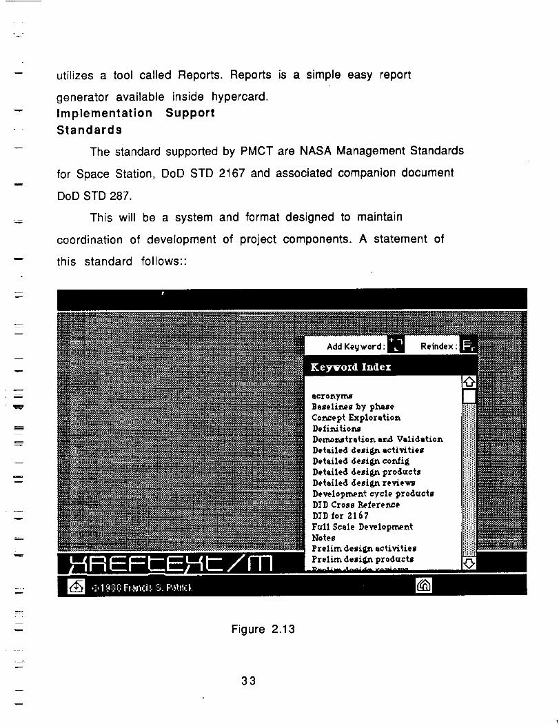
The standard supported by PMCT are NASA Management Standards
for Space Station, DoD STD 2167 and associated companion document
DoD STD 287.
This will be a system and format designed to maintain
coordination of development of project components. A statement of
this standard follows::
w
D
w
.=.
F
w
Figure 2.13
33

r
L_
w
The above is a sample of the the main screen in the on line
version of 2167. Currently the process is in place to move to 2167a
and 287.
Importance
The importance of this aspect of the Tool following this standard
is that it will allow for more structured and traceable code
development. Since this standard will become the model for all new
code development for military projects, government contracting
corporations will be required to present their development work in this
format.This standardization for such a large industry will lead to a
more evenly distributed development process for all software
development undertakings.
w
i
34
:==
w
=--
w
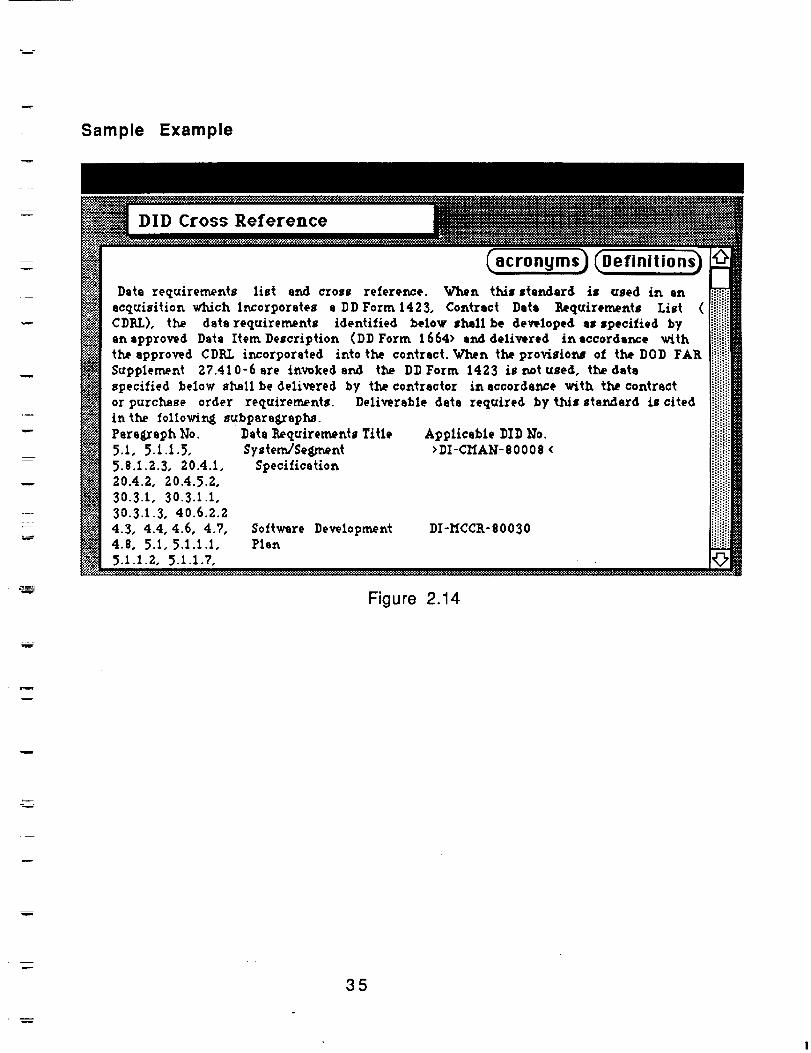
Sample Example
DID Cross Reference
Applicable DID lqo.>DI-CHAN-8000$ <
DI-HCCR-80030
Figure 2.14
_mm
Ew
35
=.w="
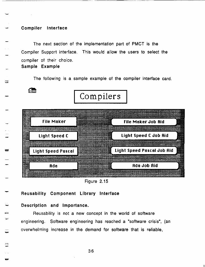
Compiler Interface
w
The next section of the implementation part of PMCT is the
Compiler Support interface. This would allow the users to select the
compiler of their choice.
Sample Example
m
m
The following is a sample example of the compiler interface card.
I Compilers I
_. Fi,eMakerJob.id _mLight Speed C Job Aid
Figure 2.15
Reusability Component Library Interface
Description and Importance.
Reusability is not a new concept in the world of software
engineering. Software engineering has reached a "software crisis", (an
overwhelming increase in the demand for software that is reliable,
36
w
mm,
m
=
i
W
efficient, maintainable, understandable, delivered on time and at
"reasonable" costs), that has brought reusability into the spotlight.This
"software crisis" has made the reusability of software an issue that
must be reconciled. Reuse is the use of previously acquired concepts
and objects in a new situation.
Reusability is a measure of the ease with which one can use
those previous concepts and objects in the new situation."With both
software production costs and the amount of new software produced
escalating annually, the application of reusability to software
development offers the potential for vast improvements in programmer
productivity which will be a key to solving the "software crisis".lf
current trends continue, in the near future many companies that have
not adopted software reuse as a standard will find themselves in a
situation where they can no longer be competitive in the contracts
arena.Boehm 1 has stated that, "the demand for new software is
increasing faster than our ability to supply it, using traditional
approaches."
With systems today being too large for a single individual to
comprehend and increased pressure to keep development costs less
than system complexity growth, and the cost of software being an
exponential function of its size, there is the creation of a no win
situation for software developers using the traditional approaches
referred to by Boehm. This, and the serious shortage of qualified
programmers to meet these demands, will become a driving force
behind reusability.
37
m
v
m.
The Software Engineering Repository Retrieval System (SERRS)
provides a mechanism for the cataloging and retrieval of various
repository components. This system implements the design methodology
of hypertext. SERRS is implemented in XREFTEXT running on top of
HYPERCARD as defined previously.
SERRS was created with the idea of allowing the maximum amount
of flexibility for traversal while maintaining a structured traversal
method, and minimizing maintenance complexities. Flexibility was built
into the basic structure to allow repositories to be added with minimal
structure changes. The basic structure is a modified hierarchical
structure stored as a key word index stack. Each element on the stack is
known as a card. From the top of the structure, forward paths available
lead to more detailed levels of the repository, one level at a time. The
backward paths of the structure are less hierarchical in that all levels
have paths that lead back to the previous level, but there are also paths
that return to the top levels. As the user becomes more familiar with the
stack, a selection can be made from the key word index that allows the
immediate selection of the desired card instead of traversing SERRS from
the top. An asterisk, (*), following a word indicates that this is a key
word for a card containing information specific to the key word.
Selection of this word will provide a forward or backward path to
another level.
m
mB
W
38
• L __.
SERRS HIERARCHY
=
[_A'BEGINNING _REUSABILITY
I
_Repository
I
_'_SERRS
_RePository
m
ComponentType 1-n
m
w
Figure 3
Source
Figure 2.16
u
39
=
m
=_
m
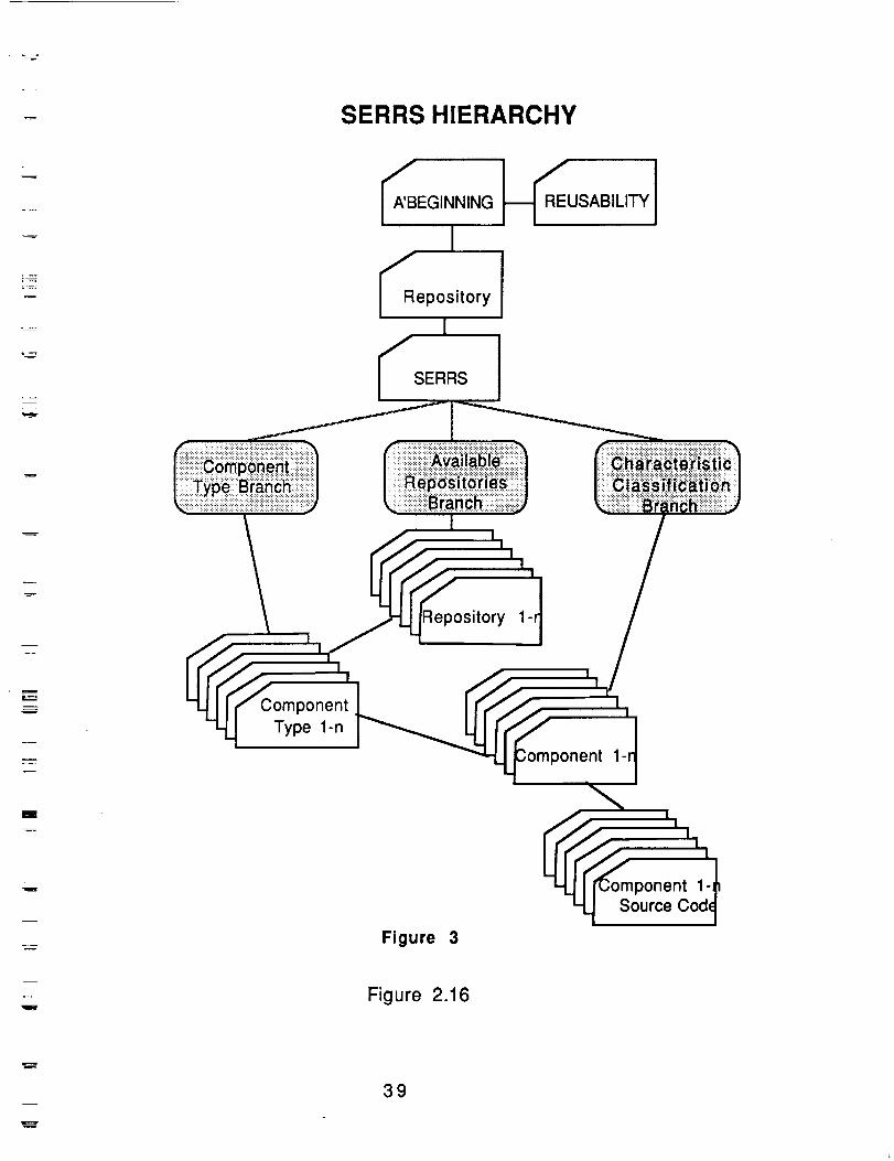
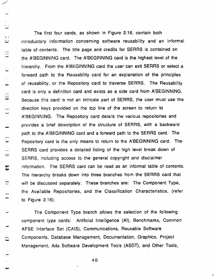
The first four cards, as shown in Figure 2.16, contain both
introductory information concerning software reusability and an informal
table of contents. The title page and credits for SERRS is contained on
the A'BEGINNING card. The A'BEGINNING card is the highest level of the
hierarchy. From the A'BEGINNING card the user can exit SERRS or select a
forward path to the Reusability card for an explanation of the principles
of reusability, or the Repository card to traverse SERRS. The Reusability
card is only a definition card and exists as a side card from A'BEGINNING.
Because this card is not an intricate part of SERRS, the user must use the
direction keys provided on the top line of the screen to return to
A'BEGINNING. The Repository card details the various repositories and
provides a brief description of the structure of SERRS, with a backward
path to the A'BEGINNING card and a forward path to the SERRS card. The
Repository card is the only means to return to the A'BEGINNING card. The
SERRS card provides a detailed listing of the high level break down of
SERRS, including access to the general copyright and disclaimer
information. The SERRS card can be read as an informal table of contents.
The hierarchy breaks down into three branches from the SERRS card that
will be discussed separately. These branches are: The Component Type,
the Available Repositories, and the Classification Characteristics, (refer
to Figure 2.16).
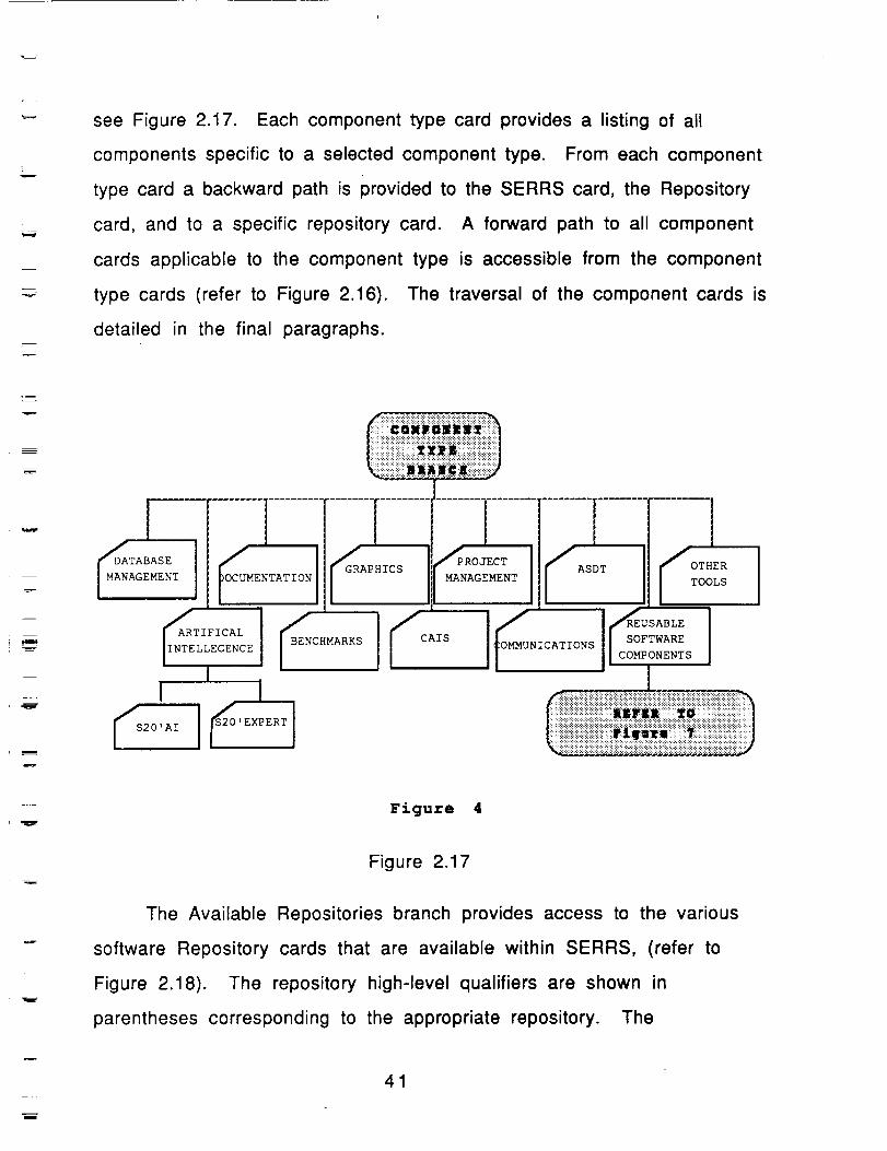
The Component Type branch allows the selection of the following
component type cards: Artificial Intelligence (AI), Benchmarks, Common
APSE Interface Set (CAIS), Communications, Reusable Software
Components, Database Management, Documentation, Graphics, Project
Management, Ada Software Development Tools (ASDT), and Other Tools,
40
r
w
=__
see Figure 2.17. Each component type card provides a listing of all
components specific to a selected component type. From each component
type card a backward path is provided to the SERRS card, the Repository
card, and to a specific repository card. A forward path to all component
cards applicable to the component type is accessible from the component
type cards (refer to Figure 2.16). The traversal of the component cards is
detailed in the final paragraphs.
m
CAIS
mH--_.
IO__UNICATIONS _USABLEI il
Figure 4
Figure 2.17
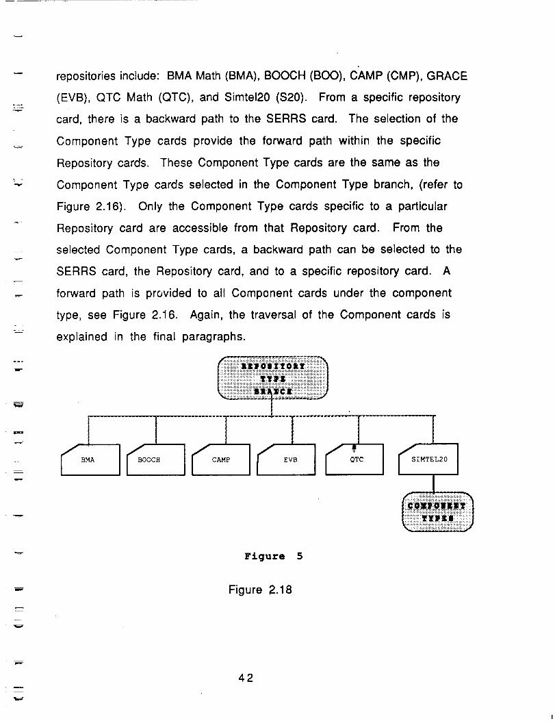
The Available Repositories branch provides access to the various
software Repository cards that are available within SERRS, (refer to
Figure 2.18). The repository high-level qualifiers are shown in
parentheses corresponding to the appropriate repository. The
41
=
t
repositories include: BMA Math (BMA), BOOCH (BOO), CAMP (CMP), GRACE
(EVB), QTC Math (QTC), and Simtel20 ($20). From a specific repository
card, there is a backward path to the SERRS card. The selection of the
Component Type cards provide the forward path within the specific
Repository cards. These Component Type cards are the same as the
Component Type cards selected in the Component Type branch, (refer to
Figure 2.16). Only the Component Type cards specific to a particular
Repository card are accessible from that Repository card. From the
selected Component Type cards, a backward path can be selected to the
SERRS card, the Repository card, and to a specific repository card. A
forward path is provided to all Component cards under the component
type, see Figure 2.16. Again, the traversal of the Component cards is
explained in the final paragraphs.
I IIS
Figure 5
L _
E
Figure 2.18
42
L
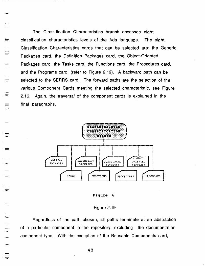
The Classification Characteristics branch accesses eight
classification characteristics levels of the Ada language. The eight
Classification Characteristics cards that can be selected are: the Generic
Packages card, the Definition Packages card, the Object-Oriented
Packages card, the Tasks card, the Functions card, the Procedures card,
and the Programs card, (refer to Figure 2.19). A backward path can be
selected to the SERRS card. The forward paths are the selection of the
various Component Cards meeting the selected characteristic, see Figure
2.16. Again, the traversal of the component cards is explained in the
final paragraphs.
. =
E :
uw
!_pGAENERIC
CKAGES IFUNCTIONAL
PACKAGES
TAS SI CT'O Sj CEOURESJ OG MSI
Figure 6
Figure 2.19
Regardless of the path chosen, all paths terminate at an abstraction
of a particular component in the repository, excluding the documentation
component type. With the exception of the Reusable Components card,
43
L_
m
Y
B
v
m
selection of a Component card provides the user with a prologue
explaining the operations performed by the selected component and a list
of all associated files residing in the corresponding repository. The
basic path structure provided for the component cards is a backward path
to a specific repository card, a backward path to the Repository card, a
backward path to a specific classification characteristics card, and/or a
backward path to a specific Component Type card as applicable. Due to
storage constraints, only selected Component cards have forward paths
to the applicable Component Source Code card, which makes up the
bottom level of the hierarchy, (refer to Figure 2.16). From the prologue
provided on the selected Component Card, the Component Source Code
card can be selected from the associated files list and viewed. These
files are identifiable by an "A" following the repository qualifier (i.e.
S20A°BIT). Only a backward path to the Component card is provided from
the Component Source Code card.
In the case of the Reusable Components card, a further
hierarchical break down is provided for math components and structure
components. This further break down is provided because of the
interest in the components falling under these categories. All other
components listed on the Reusable Components card are selected and
traversed in the manner described above, so the traversal method will
not be re-iterated. From the Reusable Components Card, math
components and structure Components can be traversed by the Math
card, the Structures card, a Repository Math card, or a Repository
Structures card. The backward paths for the Math card and the
Structures card returns to the Reusable Components card. The forward
paths from the Math card are to the Math Component Type cards. The
forward paths from the Structures card are to the Structures
Component Type cards. The backward paths from the Math Component
Type cards are to the Reusable Components card, and the Math card.
The forward path is to the Math Component cards. The backward paths
44
w
E--
L_
i
m
q
m
from the Structures Component Type cards are to the the Reusable
Components card, and the Structures card. The forward path is to the
Structures Component cards. The backward path from the Repository
Math card and the Repository Structures card is to the Reusable
Components card. The forward path from the Repository Math card is to
the Math Component cards. The forward path from the Repository
Structures card is to the Structures Component cards. Once either the
Math Component cards or the Structures Component cards have been
selected, traversal of these cards occurs exactly as traversal of the
Component cards in the previous paragraph occurred.
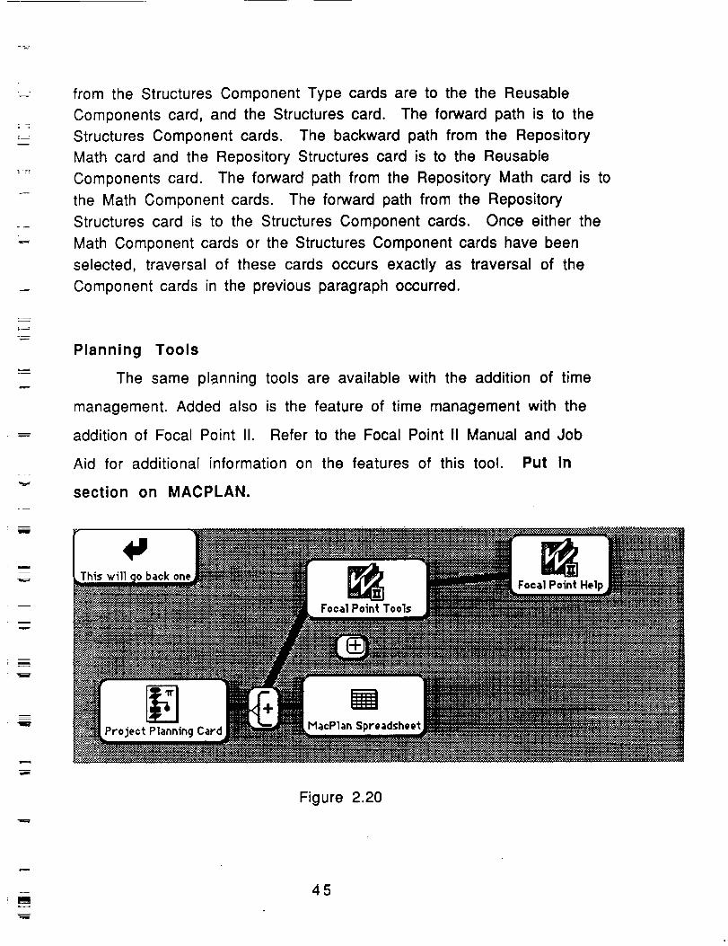
Planning Tools
The same planning tools are available with the addition of time
management. Added also is the feature of time management with the
addition of Focal Point I1. Refer to the Focal Point II Manual and Job
Aid for additional information on the features of this tool. Put in
section on MACPLAN.
Figure 2.20
m
m
45
=
Description.
The addition of Focal Point II to the planning scenario is to allow
for a more flexible monitorable planning process. Before discussion of
the planning process it is important to understand the importance of
monitoring of the planning process in the overall Software Engineering
Scenario.
The Software Maturity Model
and The PMCT
In Section I of this report the subject of the software assessment
was discussed. This section will be on the inclusion of major parameters
to assist in the collection of the data for the PMCT. A major focus of
activity will be on the importance of applying technology to the
improvement of the state of practice in software engineering. The goal of
this program is to develop an experimental software engineering platform
that can serve as a research vehicle to carry software research into the
90's and beyond. This project is a first step in establishing this research
program. There are two thrusts to this program, one is Automation, and
the other is Quality.
The introduction of quality in the software process is quite a new and
unproven idea. This paper suggests some criteria based on tried and proven
methods for quality increase and the application of these criteria to a
software project. Quality improvements can be made in the software
engineering process, if these criteria are built into the supporting
environment. The foundation for a system that will support traceability must
include a mature software process model. For the purposes of this paper,
software process modeling is defined as a methodology that encompasses a
46
z--
--=
representation approach, comprehensive analysis capabilities, and the
capability to make predictions regarding the effects of changes to a process.
.Watts Humphrey 1 describes five levels of software maturity, and it is
important to understand this maturity to appreciate the necessity for
traceability in a support environment. These five levels of software maturity
are:
1. Initial - Until a process is under statistical quality control, orderly
progress in process improvement is not possible. While there are
many degrees of statistical quality control, the first step is to
achieve rudimentary predictability of schedules and cost.
Approximately 87% of the companies observed in a study by the
Software Engineering Institute were at level one in the maturitymodel. One of the contributing factors to this grade level is the
absence of traceability 2.
2. Repeatable - A stable process with repeatable levels of quality
control, by initiating rigorous project management of commitments,cost, schedules, and changes.
3. Defined - The organization has defined the process as a basis for
consistent implementation and better understanding. At this point
advanced technology can be usefully introduced. In the above study
done at the Software Engineering Institute, there were no companies
at level three or above, only a few projects within given companies.
4. Managed - The organization has initiated comprehensive process
measurement and analysis. This is when the most significant quality
improvements begin.
5. Optimizing - The organization now has a foundation for continuing
improvement and optimization of the process.
A contributing factor to achieving level four and level five in the
maturity model will be the introduction of measurement into the software
1Humphrey, Watts, Managing The Software Process, Addison Wesley, 1989.2Humphrey, Watts, Kitson, D.H., Kasse, Tim, The State of Software Engineering Practice: APreliminary Report, Technical Report CMU/SEI-89-TR-1, Feb 1989.
47
=
m
m
process, and the utilization of these measurements to redefine and optimize
the software engineering process. While there are other factors involved in
the maturing of the software process, the primary objective is to achieve a
controlled and measured process for the foundation of the product
development. In the development of the Software Assessment Procedures 1,
the Software Engineering Institute tried to establish guidelines that would
help software developers discover the level currently achieved, and to
prescribe a formula for moving from one level to another. Requirements
traceability, and the importance of the automation of requirements
traceability as an integral part of the quality software process will be a
major contributing factor to the progress in level of maturity of a software
organization.
There is an increased demand for the inclusion of traceability at all
levels of the software development process. Computer Assisted Software
Engineering research has placed too much emphasis on trying to answer
the questions concerning software life-cycle support, and not on trying to
define what the software process is all about. It is of utmost importance
to carefully distinguish between the idea of process and life-cycle. A
process will be thought of as an ongoing activity, where a life-cycle will
have specific beginning and ending tasks. The concept of traceability in a
product belongs to the life-cycle aspects of the project, but the idea of
traceability is a process that must transcend the individual process. It
must be an integral part of the software development environment, and it
must become an integral component of the idea of quality in the software
engineering process.
1A Software Assessment for Government Contractors
48
H
If you would ask a fellow worker, student, or professor the
question, "Are you for quality?" , they would overwhelmingly respond
Yes. If everyone is for quality, and quality is an integral part of the
software process, then why is the production of quality software so hard?
The problem of quality in the production of software stems from adoption
of the philosophy of appraisal as a means of producing good quality
software, instead of prevention. "Quality is conformance to
requirements". 1 Phil Crosby symbolizes the process of quality by the
establishment of four quality absolutes. These are
1. A Definition of Quality -
2. A System for Quality
appraisal
3. Performance Standards for Quality- Zero Defects
4. Measurement to the Performance Standards - The Price of
Nonconformance.
Conformance to requirements
Prevention instead of inspection and
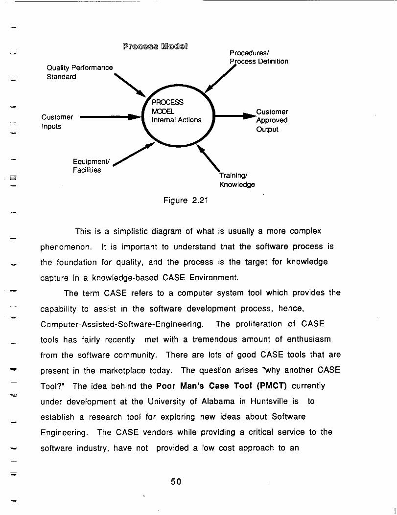
Crosby describes a process by the following diagram.
Zw
1Crosby, Phillip, Quality Improvement Through Defect Prevention: The Individual's Role. PhilCrosby Associates, Inc., 1985.
49
=__
Quality Performance
Standard
Customer
Inputs
Procedures/Process Definition
MOOEL Customer
Internal Actions Approved
Output
Equipment/Facilities
Figure 2.21
Training/
Knowledge
w
This is a simplistic diagram of what is usually a more complex
phenomenon. It is important to understand that the software process is
the foundation for quality, and the process is the target for knowledge
capture in a knowledge-based CASE Environment.
The term CASE refers to a computer system tool which provides the
capability to assist in the software development process, hence,
Computer-Assisted-Software-Engineering. The proliferation of CASE
tools has fairly recently met with a tremendous amount of enthusiasm
from the software community. There are lots of good CASE tools that are
present in the marketplace today. The question arises "why another CASE
Tool?" The idea behind the Poor Man's Case Tool (PMCT) currently
under development at the University of Alabama in Huntsville is to
establish a research tool for exploring new ideas about Software
Engineering. The CASE vendors while providing a critical service to the
software industry, have not provided a low cost approach to an
50
w
experimental platform for the study of the software process. The idea of
an experimental platform to explore new techniques, methods, policies,
and environments gives the software engineering community the ability to
try new approaches that would not be feasible within the constraints of
the software process. The fact that CASE tools are in great demand is
partially due to the change in software needs. Programs should be
efficient, easily maintained and modifiable, however this is not always
the case. Large Embedded Software Systems such as the software for
NASA's Manned Space Station and the software support for the Strategic
Defense Initiative call for the support of an efficient organizational tool
designed to support the software engineering process. Many times, the
process and the product are poorly documented and this leads to problems
in the conformance/non-conformance determination. The use of
knowledge-based CASE tools allows documentation to be generated as an
active part of the system construction and not be a burden to the overall
purpose. Therefore, the integration of, change of, re-evaluation of, and
implementation of the entire system should be performed with the
minimum amount of effort. A fundamental objective of the research
program at University of Alabama in Huntsville is the introduction of
quality as a measurable component of the software support environment,
and the inclusion of metrics to support level of improvements in the
Software Assessments.
In the first version the pert chart was the significant portion of the
planning process. This is implemented with MacProject II. It features
schedule charts, calendars, resource tables, fixed cost tables, cash
flow charts, and task time lines. The schedule charts are made of task
51
bosses joined together with lines to show the sequence of events.The
critical path is marked with a bold line, so the analyst can easily see
which task has to be done next for progress to continue smoothly.If a
task is a major point in the project it can be marked as a milestone.
As the project progresses tasks that are completed can be marked
finished.You can list up to eight resources per task, and because
different resources will have different work weeks, work week
calendars are provided.In each project or subproject there are eight
calendars available, each of these calendars can be assigned to a
particular resource.MacProject II uses the calendars to calculate the
expenses per week, and that figure is entered automatically in the cash
flow table.The fixed qost table is used for one time expenses or income
such as tools, equipment, and loans. The fixed cost table is added to
the cash flow table, so that the planner will know at any one time how
much money is available. The task time line is a graph showing the
progress of the project. It shows the percent completed of each task.
This gives a user a good idea where he stands and which tasks need
more attention. Any changes made in the number of resources or cost
will automatically be reflected in the appropriate tables and graphs.
w
52
w
Section III
Requirements Tracability in the
Poor Man's CASE Tool An important task in the systems development
process is to determine if the top-level software requirements are correctly
represented in the final level of delivered product. Requirements Traceability
is a generic term used to refer to tracking software requirements through to
final code. This process usually starts with the scanning of the software
development document to extract the corresponding software requirements
and the corresponding design. For a large scale software project this can be
an enormous volume of collected data.
There have been several attempts at the automation of the Requirements
Traceability Process 1234 Using more traditional approaches the idea of
traceability belongs in the domain of documentation and bookkeeping. ARTS 5
is described as a bookkeeping program that operates on a database consisting
of system requirements and their attributes. While the storing of the
bookkeeping information is important in the traceability process, the
knowledge associated with traceability needs a computational paradigm that
is similar conceptually to the traceable process. This natural mechanism is
found in the explanation mechanism of knowledge based systems. Reifer and
Marciniak6 suggest a knowledge-based approach to the software life-cycle
1Dorfman, M, and Flynn, M. ARTS- An Automated Requirements Traceability System, TheJournal of Systems and Software, Vol. 4,No. 1, pp 63-74, 1984.2Sciortino, J, Dunning, D., Proceedings of the AIANIEEE 6th Digital Avionics SystemsConference. Baltimore, Md. 1985.3pirnia, S.,Hayek, M., NAECON 1981. Proceedings. pages 389-394.4LaGrone, D., Wallach E, Requirements Traceability using DSSD,Tooling up for the SoftwareFactory, Feedback 86, Topeka, KS.5Dorfman, M, and Flynn, M. ARTS- An Automated Requirements Traceability System, TheJournal of Systems and Software, Vol. 4,No. 1, pp 63-74, 1984.6Reifer, D, Marciniak,J. Software Acquisition Management, John Wiley Press To Be Published.
53
w
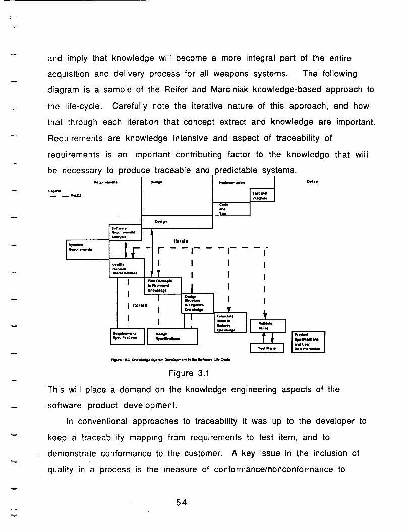
and imply that knowledge will become a more integral part of the entire
acquisition and delivery process for all weapons systems. The following
diagram is a sample of the Reifer and Marciniak knowledge-based approach to
the life-cycle. Carefully note the iterative nature of this approach, and how
that through each iteration that concept extract and knowledge are important.
Requirements are knowledge intensive and aspect of traceability of
requirements is an important contributing factor to the knowledge that will
be necessary to produce traceable and predictable systems.
_Ir,_onts
Atmlysle
__i_cProblem
Chat_tedetfee
Legend
m _flq, JD
Requlrem_ts Oe,.Ign
O_gn
t,IY
I Find Conceptsto RelXe I.mt
Knowledge
I IIterate I
I I
,--j[-[ Sl_lflcdom _:ec:Jfl_o_
Iterate
i Teet
•.e_ i H_,-,- jToot
I I
I I
I I
Figure 1R.3 Kno_le_lge 9yetem Deve_o_eflt in the Sofivmre Life Cycle
Figure 3.1
This will place a demand on the knowledge engineering aspects of the
software product development.
In conventional approaches to traceability it was up to the developer to
keep a traceability mapping from requirements to test item, and to
demonstrate conformance to the customer. A key issue in the inclusion of
quality in a process is the measure of conformance/nonconformance to
54
v
requirements. This is usually done in the form of a traceability matrix.
However the drawback of the traceability matrix is inconsistency in the
knowledge associated with the inherent chaining structure. This chaining
structure is naturally found in production rule knowledge-based systems. A
more in-depth discussion of production rule-based systems, and the
capability of a production rule system to explain its reasoning may be
appropriate for the reader 1 2
There is an increased demand for the inclusion of traceability at all
levels of the software development process 3. The delivery of the traceability
mappings of requirements to product is often delayed until the latter steps in
the product development cycle. Quite often these mappings provide no insight
into the overall application of quality principles of Requirements
Engineering. Standards and practices usually include ways to translate top-
level requirements into some written form. Few projects establish
traceability because of the ambiguities of the written software
specification. Each prose paragraph may contain a requirement or several
requirements and likewise a requirement may be referred to by several
paragraphs. Even though these references are stored in an automated
bookkeeping form, this falls short of the real objective for traceability in
that the representation is a conceptually unnatural format. Traceable
requirements in the traditional format do not establish conceptual linkage of
requirement to requirement much less form clusters or groups of
requirements.
1
2
3DOD-STD-2167a,
55
m
The clerical burden placed on the project often deters the progress of the
product development. In conventional approaches the traceability was an
added burden, this approach introduces traceability as an integral part of the
way in which the designer thinks of the knowledge that is associated with the
design process. It is not a mechanism that is used just to show customer
satisfaction. Projects implemented with PMCT(The Poor Man's Case Tool)
will not move forward unless driven by the knowledge-based model. If the
tools for traceability are used to enhance the project development then the
clerical burden will be reduced or at least distributed over a larger portion of
the project life-cycle,
Computer-Aided Software Engineering research has placed too much
emphasis on trying to provide tools to support the bookkeeping of a software
life-cycle, only to find that the life-cycle had no mature software process to
give it foundation. It is important to carefully distinguish between the idea
of process and life-cycle. A process will be thought of as an ongoing activity,
where a life-cycle will have specific beginning and ending tasks. The concept
of traceability in a product belongs to the life-cycle aspects of the project,
but the conceptual foundation of traceability should be an integral part of the
knowledge associated with, and captured by, the process and the product.
This inherent linking of pieces of an analyzed process into a synthesized
solution transcends a one-time application of the software process. The
knowledge capture of traceability must be an integral part of the software
development environment and the quality factors in the software engineering
process. In the software maturity model 1 it is crucial that there be
measured improvement in the software process.
1Humphrey, Watts, Managing The Software Development Process, Addison Wesley, 1989.
56
w
Quality in the software process
If you would ask a fellow worker, student, or professor the question, "Are
you for quality?", the overwhelming response would be "Yes". If everyone is
for quality, and quality is an integral part of the software process, then why
is the production of quality software so difficult?
The problem of quality in the production of a product stems from adoption
of the philosophy of appraisal instead of prevention of defect, as a means of
producing good quality software. "Quality is conformance to requirements".
Phil Crosby 1 symbolizes the process of quality by the establishment of four
important quality absolutes. These are:
1. A Definition of Quality - Conformance to requirements
2. A System for Quality - Prevention instead of inspection and appraisal
3. Performance Standards for Quality- Zero Defects4. Measurement of the Performance Standards - The Price of
Nonconformance.
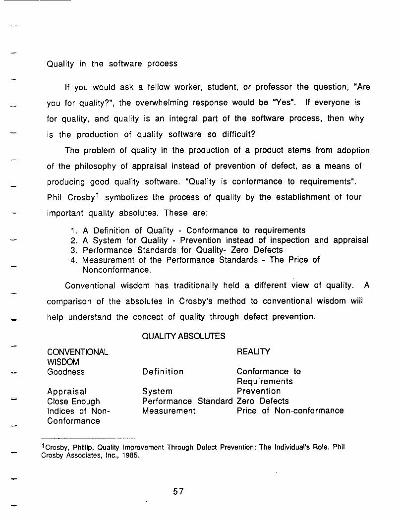
Conventional wisdom has traditionally held a different view of quality. A
comparison of the absolutes in Crosby's method to conventional wisdom will
help understand the concept of quality through defect prevention.
CONVENTIONAL
WISDOM
Goodness
AppraisalClose EnoughIndices of Non-
Conformance
QUALITY ABSOLUTES
REALITY
Definition Conformance to
Requirements
System PreventionPerformance Standard Zero DefectsMeasurement Price of Non-conformance
1Crosby, Phillip, Quality Improvement Through Defect Prevention: The Individual's Role. PhilCrosby Associates, Inc., 1985.
57
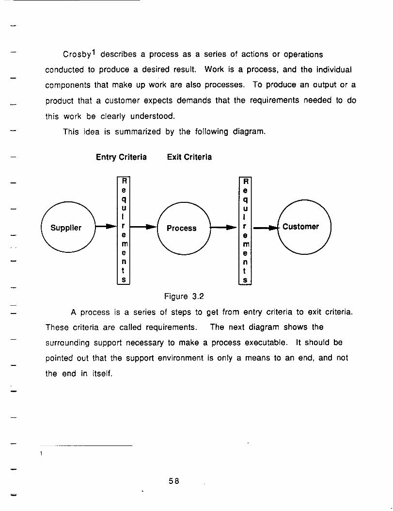
Crosby 1 describes a process as a series of actions or operations
conducted to produce a desired result. Work is a process, and the individual
components that make up work are also processes. To produce an output or a
product that a customer expects demands that the requirements needed to do
this work be clearly understood.
This idea is summarized by the following diagram.
w
w
Entry Criteria Exit Criteria
w m
R R
e e
r r
e •I"11 m
e en nt tS S
Figure 3.2
A process is a series of steps to get from entry criteria to exit criteria.
These criteria are called requirements. The next diagram shows the
surrounding support necessary to make a process executable. It should be
pointed out that the support environment is only a means to an end, and not
the end in itself.
58
w
Quality PerformanceStandard
Inputs
Process
InternalActions
/Procedures/ProcessDefinition
Outputs
Equipment/ Training/Facilities Knowledge
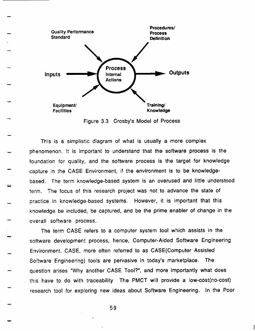
Figure 3.3 Crosby's Model of Process
This is a simplistic diagram of what is usually a more complex
phenomenon. It is important to understand that the software process is the
foundation for quality, and the software process is the target for knowledge
capture in the CASE Environment, if the environment is to be knowledge-
based. The term knowledge-based system is an overused and little understood
term. The focus of this research project was not to advance the state of
practice in knowledge-based systems. However, it is important that this
knowledge be included, be captured, and be the prime enabler of change in the
overall software process.
The term CASE refers to a computer system tool which assists in the
software development process, hence, Computer-Aided Software Engineering
Environment. CASE, more often referred to as CASE(Computer Assisted
Software Engineering) tools are pervasive in today's marketplace. The
question arises "Why another CASE Tool?", and more importantly what does
this have to do with traceability The PMCT will provide a low-cost(no-cost)
research t0ol for exploring new ideas about Software Engineering. In the Poor
59
=_m
w
!
w
i
M
n
Man's Case Tool traceability through knowledge-based approaches is the
foundation for the computer assistance. CASE vendors while providing a
needed service to the software industry, have not provided an approach to an
experimental platform for the study of the software process, much less an
economical platform. The idea of this experimental platform to explore new
techniques, methods, policies, and environments, gives the software
engineering community the ability to try new approaches that would not be
feasible within the constraints of the software process using the
conventional tool support.
The fact that CASE tools are in great demand is partially due to the
demand for change in software development. Tennant and White 1 describe the
current thought about computing and the future of computing in the following
terms. "Knowledge is a prime enabler of change in an age of computational
abundance". The use of a knowledge-based approach allows documentation to
be generated as a by-product of the knowledge associated with the system
construction process, and will not impose a burden to the product developer.
The following section shows some of the sample screens from the PMCT
and shows the importance of measurement in the quality of the produced
software. It is important to understand where in the overall environment the
traceability mechanism fits. The First Screen in the PMCT is the Main Screen.
This screen is shown here is to emphasize the importance of the separation of
process modeling issues from the other aspects of the software development
process. In the utilization of the PMCT, the first step is to establish the
software process model with which the project will be built. Humphrey 2 and
1Tennant, Harry, White, John, W. Knowledge as a Prime Enabler of Change, TexasInstruments Engineering Journal, September 1989, Vol XXX Number XXX2Humphrey
60
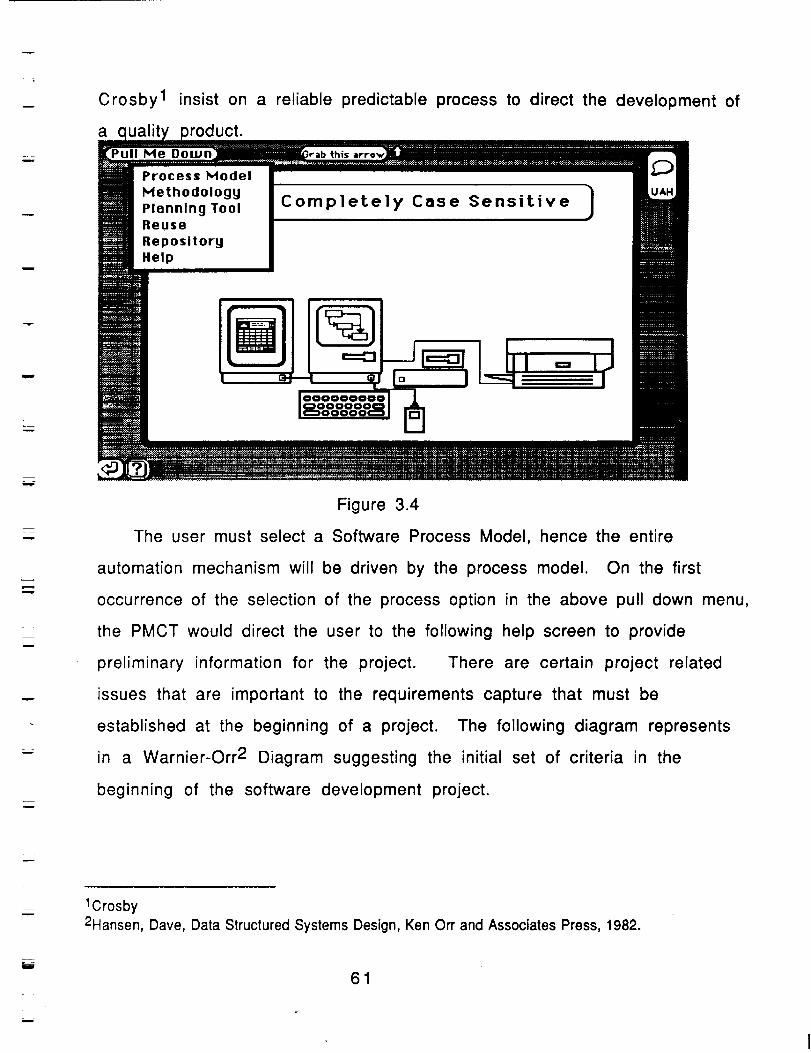
w
w
=w
w
n
m
w
L_
Crosby 1 insist on a reliable predictable process to direct the development of
a
Me
Process Model
Methodology
Planning ToolReuse
Repository
Xelp
th_s
Completely Case Sensitive I
100000¢
Figure 3.4
The user must select a Software Process Model, hence the entire
automation mechanism will be driven by the process model. On the first
occurrence of the selection of the process option in the above pull down menu,
the PMCT would direct the user to the following help screen to provide
preliminary information for the project. There are certain project related
issues that are important to the requirements capture that must be
established at the beginning of a project. The following diagram represents
in a Warnier-Orr 2 Diagram suggesting the initial set of criteria in the
beginning of the software development project.
L__w
1Crosby
2Hansen, Dave, Data Structured Systems Design, Ken Orr and Associates Press, 1982.
m
61
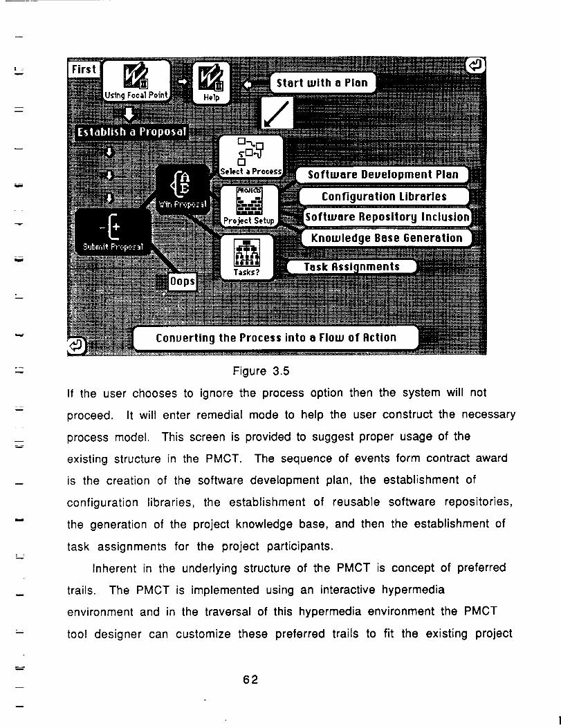
L
m
= =
W
L _
Knowledge Base Generation
w
w
Figure 3.5
If the user chooses to ignore the process option then the system will not
proceed. It will enter remedial mode to help the user construct the necessary
process model. This screen is provided to suggest proper usage of the
existing structure in the PMCT. The sequence of events form contract award
is the creation of the software development plan, the establishment of
configuration libraries, the establishment of reusable software repositories,
the generation of the project knowledge base, and then the establishment of
task assignments for the project participants.
Inherent in the underlying structure of the PMCT is concept of preferred
trails. The PMCT is implemented using an interactive hypermedia
environment and in the traversal of this hypermedia environment the PMCT
tool designer can customize these preferred trails to fit the existing project
62
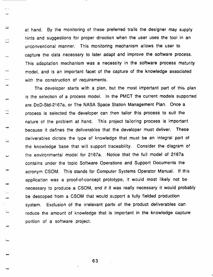
L
w
w
at hand. By the monitoring of these preferred trails the designer may supply
hints and suggestions for proper direction when the user uses the tool in an
unconventional manner. This monitoring mechanism allows the user to
capture the data necessary to later adapt and improve the software process.
This adaptation mechanism was a necessity in the software process maturity
model, and is an important facet of the capture of the knowledge associated
with the construction of requirements.
The developer starts with a plan, but the most important part of this plan
is the selection of a process model. In the PMCT the current models supported
are DoD-Std-2167a, or The NASA Space Station Management Plan. Once a
process is selected the developer can then tailor this process to suit the
nature of the problem at hand. This project tailoring process is important
because it defines the deliverables that the developer must deliver. These
deliverables dictate the type of knowledge that must be an integral part of
the knowledge base that will support traceability. Consider the diagram of
the environmental model for 2167a. Notice that the full model of 2167a
contains under the topic Software Operations and Support Documents the
acronym CSOM. This stands for Computer Systems Operator Manual. If this
application was a proof-of-concept prototype, it would most likely not be
necessary to produce a CSOM, and if it was really necessary it would probably
be descoped from a CSOM that would support a fully fielded production
system. Exclusion of the irrelevant parts of the product deliverables can
reduce the amount of knowledge that is important in the knowledge capture
portion of a software project.
63
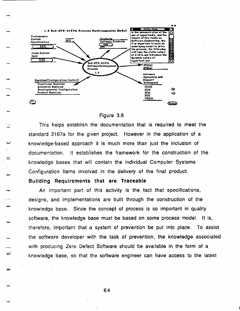
w
w
w
,,m-
41.4
E1.0 Dod-STD-2167& Prooesg K_viromm_eatel Hods| | _,_5_
in qhe derno¢_str&tton of the J_i
Prolimit_ery use 05' h_pevmed_o, a_J the
System -- __ k_q_t of" t.hls media on
$osoitiostion _ Soft,were Produ©ts So_&ve FJ_bsed_k_g, ff_e
- _ _ tt is t_po_nt to have an
Fi_l S-,tem _ "% _ / vfl] t_JJce the stifle (_4(_re__ " _ _J. / / of 2167. and _b'od_* th*
_"°*ro - J-.._ n-_.'
_ O_ere_lo_ e_d
Beseli_Coz_i_uretiot_ Control) _/ _ S_ppor_F_t_t_o_l Bueli_e _l_ Do_mes_tg_j_
Alloctte4 B_lell_ CSOM
Development _ Cos_ftguretto_ _
Product Bsseliz_ b_Pl'f c_¥Sl'I
CRISD
Figure 3.6
This helps establish the documentation that is required to meet the
standard 2167a for the given project. However in the application of a
knowledge-based approach it is much more than just the inclusion of
documentation. It establishes the framework for the construction of the
knowledge bases that will contain the individual Computer Systems
Configuration Items involved in the delivery of the final product.
Building Requirements that are Traceable
An important part of this activity is the fact that specifications,
designs, and implementations are built through the construction of the
knowledge base. Since the concept of process is so important in quality
software, the knowledge base must be based on some process model. It is,
therefore, important that a system of prevention be put into place. To assist
the software developer with the task of prevention, the knowledge associated
with producing Zero Defect Software should be available in the form of a
knowledge base, so that the software engineer can have access to the latest
64
mw
w
w
W
w
.m
w
data, knowledge, and documentation. To establish such a system Crosby 1
suggests five requirements of this system. These are:
Clear Requirements
Well-Defined Process
Proof of Process Capability
Process Control
Policies and Systems for defect prevention
Requirements Traceability is a method of demonstrating to the customer
Crosby's fourth quality absolute, the conformance or non-conformance
of the requirements of the product being produced. It is also a framework
in which knowledge can be captured about the process so that improvement
can be made in the process. Usually in the development of Applications
Software this is demonstrated by some after the fact mechanism that will
show the links between the final product documentation and the requirements
document. This is usually done by the means of a requirements traceability
matrix. In DoD-Std-2167a, the Department of Defense has mandated
traceability of requirements as a critical required component when delivering
Mission Critical Computer Resources. Requirements traceability is a method
to ensure that not only is a software system complete, but that it is also
correct. It demonstrates paths from requirements to code that the developer
can trace in either direction. These traceability links are essential in the
verification of the component in question, but are also a valuable tool in the
assessment of software changes to that component.
In light of the discussion of quality and Crosby's four absolutes, the
problem of the monitoring and mapping of conformance�non-conformance
from the process to the product is an important issue. In the use of static
1Crosby, Phillip, Quality Improvement Through Defect Prevention: The Individual's Role. PhilCrosby Associates, Inc., 1985.
65
v
w
v
L _
documents this is quite difficult. Here the concept of active knowledge bases
as software requirements are introduce into the experimental platform. It is
the building of these knowledge bases that represents the software
specification process. PMCT produces documentation as a by-product of the
knowledge capture process. Instead of being a document for traceability, the
specification for a system is an active component in the knowledge base, and
should be used to enhance the design process. The inclusion of traceability
will be implicit in the construction of production rule knowledge bases. This
knowledge base is executable and the traceability is provided through the
explanation functions of the expert system tool selected. There are typically
two types of questions that an acceptable expert systems should be able to
answer about the reasoning process. Note that these questions are not
answers to query of a database containing project information, but about the
supporting reasoning process itself. These questions are:
Why did you arrive at this conclusion?
How did you derive such an answer?
These also are two important issues(questions) in the conceptual
framework of traceability:
1. Why is this component necessary to confirm this requirement?
2. How does this component trace to its requirement?
The following shows a Computer Systems Configuration Item(CSCl) in a
real-time embedded system, created with the PMCT.
w
66
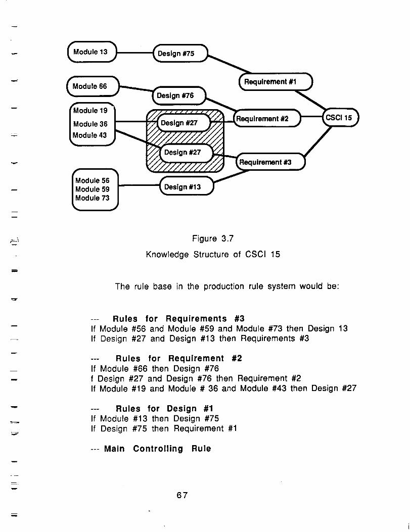
w
T
w
Module 13
Module 66
19
Module 36
Module 43
56Module 59Module 73
Design #75
n #76
Design #27
Design #27
Design #13
Requirement #1
uirement #2 15
Requirement #3
: ! Figure 3.7
Knowledge Structure of CSCI 15
The rule base in the production rule system would be:
m
w
r_
m
w
--- Rules for Requirements #3If Module #56 and Module #59 and Module #73 then Design 13
If Design #27 and Design #13 then Requirements #3
--- Rules for Requirement #2
If Module #66 then Design #76
f Design #27 and Design #76 then Requirement #2If Module #19 and Module # 36 and Module #43 then Design #27
--- Rules for Design #1
If Module #13 then Design #75
If Design #75 then Requirement #1
--- Main Controlling Rule
67
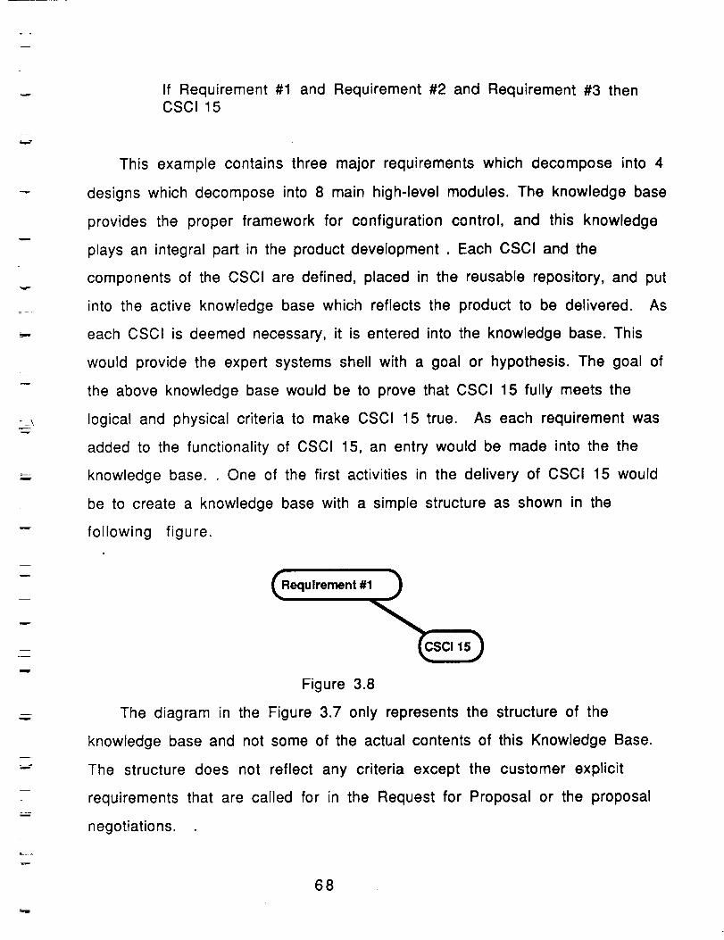
v
w
w
If Requirement #1 and Requirement #2 and Requirement #3 thenCSC115
This example contains three major requirements which decompose into 4
designs which decompose into 8 main high-level modules. The knowledge base
provides the proper framework for configuration control, and this knowledge
plays an integral part in the product development . Each CSCI and the
components of the CSCI are defined, placed in the reusable repository, and put
into the active knowledge base which reflects the product to be delivered. As
each CSCI is deemed necessary, it is entered into the knowledge base. This
would provide the expert systems shell with a goal or hypothesis. The goal of
the above knowledge base would be to prove that CSCI 15 fully meets the
logical and physical criteria to make CSCI 15 true. As each requirement was
added to the functionality of CSCI 15, an entry would be made into the the
knowledge base. One of the first activities in the delivery of CSCI 15 would
be to create a knowledge base with a simple structure as shown in the
following figure.
m
m
Figure 3.8
The diagram in the Figure 3.7 only represents the structure of the
knowledge base and not some of the actual contents of this Knowledge Base.
The structure does not reflect any criteria except the customer explicit
requirements that are called for in the Request for Proposal or the proposal
negotiations.
68
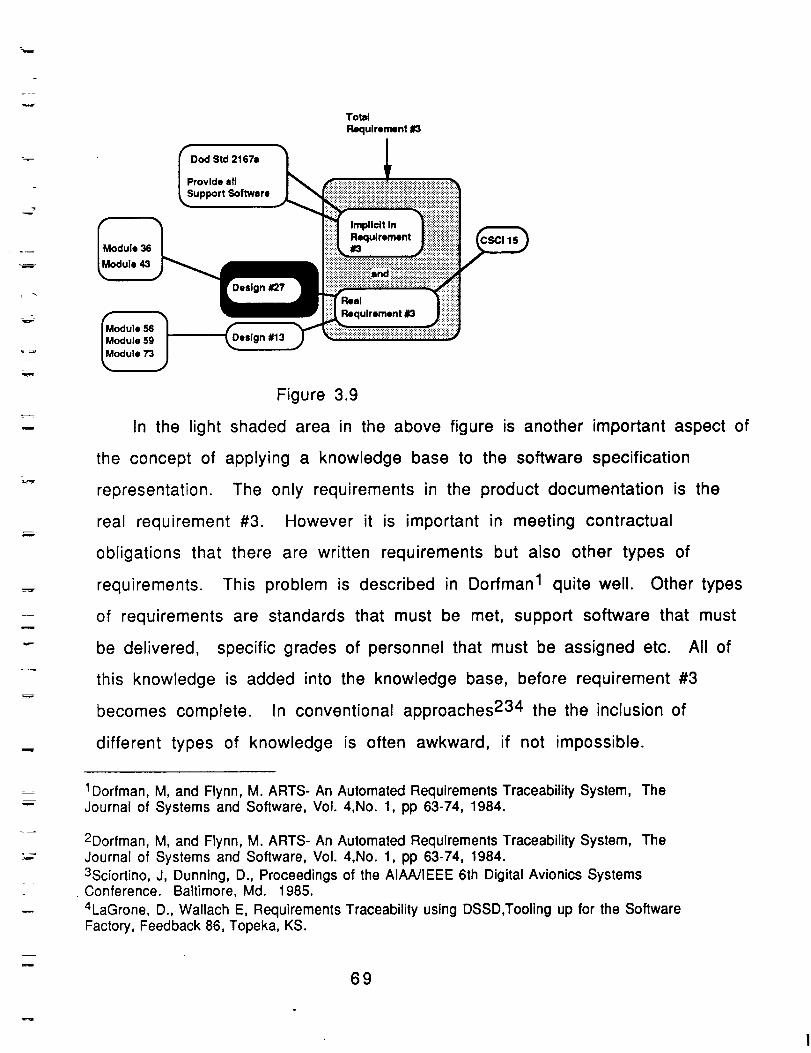
=
--"-Jr
m
Total
Requirement #3
IspDO_St,,=_+_.l
r°Vldret aLftwa re I_ _iiiiiiiiiiiiiiiiii_i!i_ii!iiiiiiiiiiii_iiiii_i_
+,o iiiiiiiiiiiiiiii!i!iiiiiiiiiiiiiiiiiiililililiiiiiiiiiiiiii!iiiillH Implicit In _!i!!iiiiiiiiiiii:iiiiiiii
_Requlrement _ _;_ _
J ii+i+!i!iii!iii',iiiii!Miiiiiiiiii!i i::!i!i!i!i!ii!ii!iiiii!ii!i!!i!iiil
[Real
_odule _,ll __,ulrementCl ++++l
i.o,u,. (o.,,+.odule 73
Figure 3.9
In the light shaded area in the above figure is another important aspect of
the concept of applying a knowledge base to the software specification
representation. The only requirements in the product documentation is the
real requirement #3. However it is important in meeting contractual
obligations that there are written requirements but also other types of
requirements. This problem is described in Dorfman I quite well. Other types
of requirements are standards that must be met, support software that must
be delivered, specific grades of personnel that must be assigned etc. All of
this knowledge is added into the knowledge base, before requirement #3
becomes complete. In conventional approaches 234 the the inclusion of
different types of knowledge is often awkward, if not impossible.
1Dorfman, M, and Flynn, M. ARTS- An Automated Requirements Traceability System, TheJournal of Systems and Software, Vol. 4,No. 1, pp 63-74, 1984.
2Dorfman, M, and Flynn, M. ARTS- An Automated Requlrements Traceability System, TheJournal of Systems and Software, Vol. 4,No. 1, pp 63-74, 1984.
3Sciortino, J, Dunning, D., Proceedings of the AIAA/IEEE 6th Digital Avionics SystemsConference. Baltimore, Md. 1985.
4LaGrone, D., Wallach E, Requirements Traceability using DSSD,Tooling up for the SoftwareFactory, Feedback 86, Topeka, KS.
69
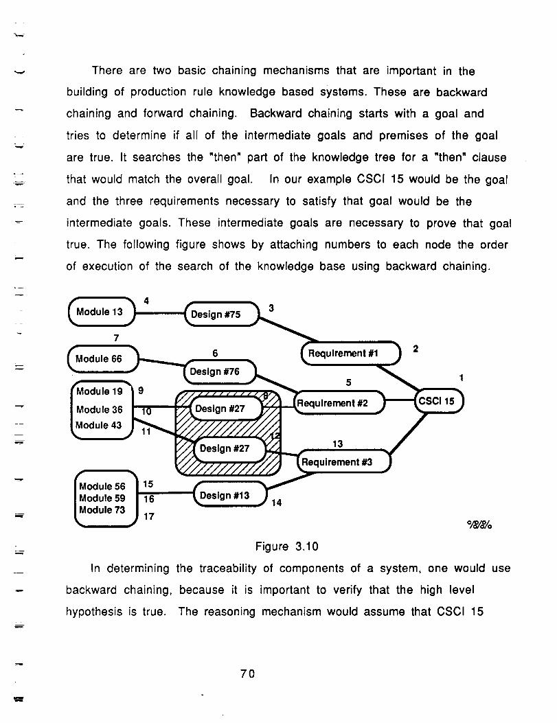
t_
L_
m
There are two basic chaining mechanisms that are important in the
building of production rule knowledge based systems. These are backward
chaining and forward chaining. Backward chaining starts with a goal and
tries to determine if all of the intermediate goals and premises of the goal
are true. It searches the "then" part of the knowledge tree for a "then" clause
that would match the overall goal. In our example CSCI 15 would be the goal
and the three requirements necessary to satisfy that goal would be the
intermediate goals. These intermediate goals are necessary to prove that goal
true. The following figure shows by attaching numbers to each node the order
of execution of the search of the knowledge base using backward chaining.
Module 13 in #753
7
6 Requirement #1 2Module 66
n #765
19 9
Module 36 Design #27 _Requirement #2
Module 43
Design #27 13
uirement #3
#1356 15
Module 59 16Module 73
17
14
15
0/Oo/o%
Figure 3.10
In determining the traceability of components of a system, one would use
backward chaining, because it is important to verify that the high level
hypothesis is true. The reasoning mechanism would assume that CSCI 15
70
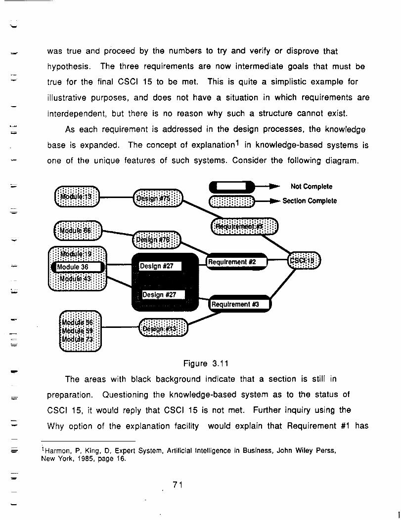
was true and proceed by the numbers to try and verify or disprove that
hypothesis. The three requirements are now intermediate goals that must be
true for the final CSCI 15 to be met. This is quite a simplistic example for
illustrative purposes, and does not have a situation in which requirements are
interdependent, but there is no reason why such a structure cannot exist.
As each requirement is addressed in the design processes, the knowledge
base is expanded. The concept of explanation 1 in knowledge-based systems is
one of the unique features of such systems. Consider the following diagram.
w
NotComplete
_ Section Complete
v
..,..
=
z
w
Module36 Design#27Requirement#2
#27
Requirement#3
Figure 3.11
The areas with black background indicate that a section is still in
preparation. Questioning the knowledge-based system as to the status of
CSCI 15, it would reply that CSCI 15 is not met. Further inquiry using the
Why option of the explanation facility would explain that Requirement #1 has
i Harmon, P, King, D, Expert System, Artificial Intelligence in Business, John Wiley Perss,New York, 1985, page 16.
71
m
been meet, but that Design #27 is still not satisfactory to complete
Requirement #2 or Requirement #3. All of the components of Design #27 are
complete except Module #36. If the system was asked, "How did it arrive at
this conclusion?", it would explain that Module #36 was necessary to
complete Design #27 and that Design #27 was necessary to complete
Requirement #3 and Requirement #2, and that was all a part of evidence need
to arrive a true hypothesis for CSCI 15. If this was a complex system, there
could be hundreds of cases that could possibly contain this scenario. It is
very difficult to reason about that kind of information in the bookkeeping
style of a requirements traceability matrix, even with the support of the
project databases 1234 in more automated scenarios. By capturing the
requirements, design and implementation as premises in a knowledge base,
the specification becomes an active component in the system and not just a
passive part of some boring documentation. The documentation stays current
because it is an active part of the design process.
There is another way to use the knowledge captured in the existing
knowledge base. It was not until after the knowledge base was built in the
first attempt that this feature was discovered. The hypothesis not met in the
backward chaining of the knowledge base are known, but what is really
important is all of the affected sections of the entire product from a given
module, design, or requirement. Data-driven or forward chaining knowledge-
based systems reason from premise to conclusion (the search of the if portion
1Dorfman, M, and Flynn, M. ARTS- An Automated Requirements Traceability System, TheJournal of Systems and Software, Vol. 4,No. 1, pp 63-74, 1984.2Sciortino, J, Dunning, D., Proceedings of the AIAA/IEEE 6th Digital Avionics SystemsConference. Baltimore, Md. 1985.3LaGrone, D., Wallach E, Requirements Traceability using DSSD,Tooling up for the SoftwareFactory, Feedback 86, Topeka, KS.4
72
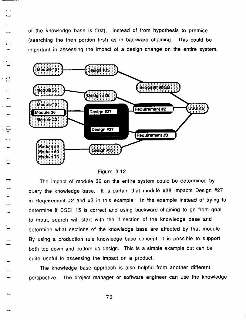
of the knowledge base is first), instead of from hypothesis to premise
(searching the then portion first) as in backward chaining. This could be
important in assessing the impact of a design change on the entire system.
w
w
Module 36 Design #27drement #2
Design #27
Requirement #3
Figure 3.12
The impact of module 36 on the entire system could be determined by
query the knowledge base. It is certain that module #36 impacts Design #27
in Requirement #2 and #3 in this example. In the example instead of trying to
determine if CSCI 15 is correct and using backward chaining to go from goal
to input, search will start with the if section of the knowledge base and
determine what sections of the knowledge base are affected by that module.
By using a production rule knowledge base concept, it is possible to support
both top down and bottom up design. This is a simple example but can be
quite useful in assessing the impact on a product.
The knowledge base approach is also helpful from another different
perspective. The project manager or software engineer can use the knowledge
73
_B"m
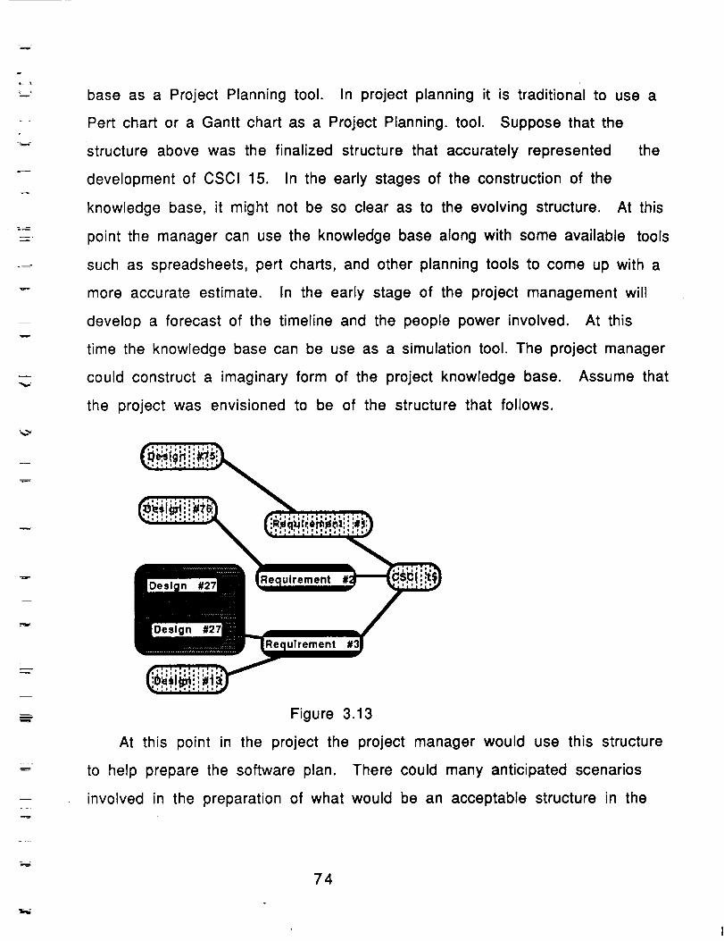
_v
i
_=_
w
base as a Project Planning tool. In project planning it is traditional to use a
Pert chart or a Gantt chart as a Project Planning. tool. Suppose that the
structure above was the finalized structure that accurately represented the
development of CSCI 15. In the early stages of the construction of the
knowledge base, it might not be so clear as to the evolving structure. At this
point the manager can use the knowledge base along with some available tools
such as spreadsheets, pert charts, and other planning tools to come up with a
more accurate estimate. In the early stage of the project management will
develop a forecast of the timeline and the people power involved. At this
time the knowledge base can be use as a simulation tool. The project manager
could construct a imaginary form of the project knowledge base. Assume that
the project was envisioned to be of the structure that follows.
m Figure 3.13
At this point in the project the project manager would use this structure
to help prepare the software plan. There could many anticipated scenarios
involved in the preparation of what would be an acceptable structure in the
74
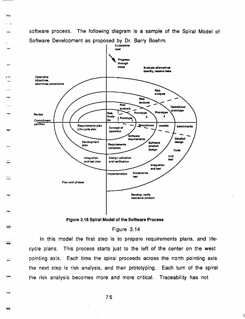
_r.W
w software process.
Software Development as proposed by Dr. Bar_ Boehm.Cumulative
coat
_k Prognma
through
atepe
Determine
objectives,elterntives,oonM taints
The following diagram is a sample of the Spiral Model of
Evak, ate alternatlvu
identify, rmmlve risks
ReviewAnely-
I Protctyl_Commitment sis I
Requirements plan ""-Life cycle plan Concept of
operation
Development
plan
nKlulrements
ulrementsvalidation product
design
Integration Oellgn validation
and test plan and verification
integrationand test
modeie
Implementation Acceptancetest
benchmarkm
Dot4dktddanlgn
Coda
Unntest
Develop, verifynext-level product
Figure 2.18 Spiral Model of the Software Process
Figure 3.14
In this model the first step is to prepare requirements plans, and life-
cycle plans. This process starts just to the left of the center on the west
pointing axis. Each time the spiral proceeds across the north pointing axis
the next step is risk analysis, and then prototyping. Each turn of the spiral
the risk analysis becomes more and more critical. Traceability has not
75
=
E
traditionally been consider a part of the calculation of the risk associated
with the turning if the spiral, however if the concept of traceability was an
integral part of the preparation of these risk analysis, and this knowledge
associated with the risk was attached to the executable traceable knowledge
base, then the evaluation of risk would first be more manageable, and more a
part of the preparation of the requirements, design and implementation of the
software product.
Certainty Factors represent the confidence in a piece of evidence. There
are numerous ways of representing certainty factors. Assume the use of
uncertainty factor such as the uncertainty factors of Emycin 1. as represented
in the following diagram. Often it is difficult to communicate uncertainty in
the software development plan. By using a knowledge base that allows for
manipulation of the uncertainty factors, this presents a help feature for the
manager and software engineer to provide a common grounds for
communication of issues that are related to risk. The following figure is a
sample of two ways to attach certainty to rule base. These two ways are to
have certainty factors that range from -1.0 to +1.0 or to have certainty
factors that range from 0% to 100%.
B
L
= =
1Buchanan, B. and Shortlife, E. Rule-Based Expert Systems: The Stanford Experiment
m
w
76
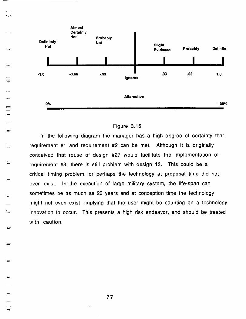
DefinitelyNot
Almost
CertainlyNot Probably
NotSllghtEvidence Probably Deflnlte
Ignored
m
Alternative
(P/o 100%1
Figure 3.15
In the following diagram the manager has a high degree of certainty that
requirement #1 and requirement #2 can be met. Although it is originally
conceived that reuse of design #27 would facilitate the implementation of
requirement #3, there is still problem with design 13. This could be a
critical timing problem, or perhaps the technology at proposal time did not
even exist. In the execution of large military system, the life-span can
sometimes be as much as 20 years and at conception time the technology
might not even exist, implying that the user might be counting on a technology
innovation to occur. This presents a high risk endeavor, and should be treated
with caution.
77
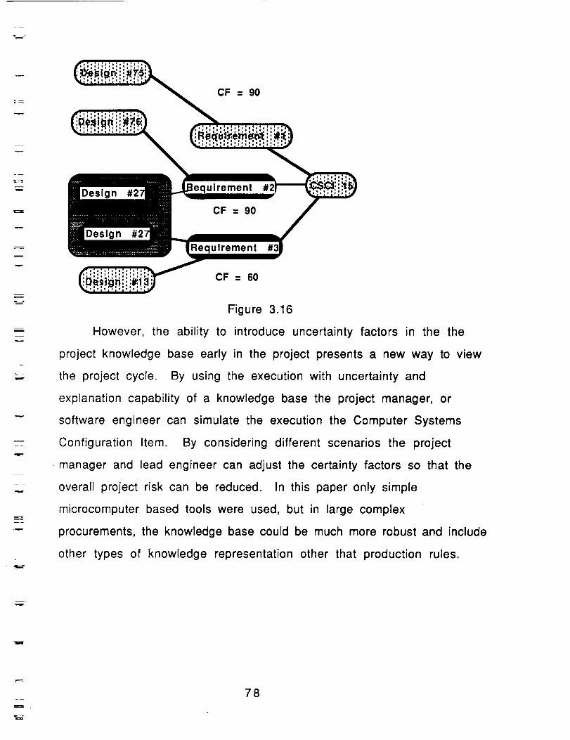
B
w
v
M
==
CF = 90
Design
Design
uirement
CF = 90
uirement
CF = 60
Figure 3.16
However, the ability to introduce uncertainty factors in the the
project knowledge base early in the project presents a new way to view
the project cycle. By using the execution with uncertainty and
explanation capability of a knowledge base the project manager, or
software engineer can simulate the execution the Computer Systems
Configuration Item. By considering different scenarios the project
manager and lead engineer can adjust the certainty factors so that the
overall project risk can be reduced. In this paper only simple
microcomputer based tools were used, but in large complex
procurements, the knowledge base could be much more robust and include
other types of knowledge representation other that production rules.
B .
78

_m
E
mrw
Section IV
Formalization of Tool
79
m
M
m
Introduction
Building large-scale real-time embedded systems mandates a
consistent and robust mechanism for process representation. A Petri net
is a modelling tool used in the design and analysis of systems. The
expert system language OPS-5 has a similar execution strategy to a Petri
net model, and hence Petri nets may be simulated using the OPS-5-1ike
languages. Likewise Hypermedia based applications lend themselves
nicely to representation with Petri Nets.
The system described takes a Petri net for its input, selects the proper
medium for modelling the features, and then generates the simulator
input. The actual model is executed from the petri-net representation,
and each step in the process is demonstrated using a visual trace of the
knowledge base execution. The knowledge base is built visually, and the
execution is shown visually.
Issues of importance in the building of distributed systems involve
issues such as timing constraints and concurrency. However using
conventional techniques it is difficult to follow the flow of control
conceptually .. Petri Nets have received popular acceptance in the area of
hardware representation, discrete event simulation, and some types of
artificial intelligence applications. It is becoming more important in the
building of distributed real-time embedded systems to have the
capability to model these systems using more formal methods. The
formal method introduced in this presentation is a modified version of
Petri nets called HNPN's, Hypermedia-based Numerical Petri Nets.
Petri net models are popular in specifying and analyzing distributed
systems, parallel systems, and communication protocols. Some
researchers are beginning to apply Petri nets modeling techniques to
8O
m
w
specify, verify and analyze distributed real-time embedded systems. The
example included in this research is a complex diagnostic system
simulation for the Space Shuttle Main Engine. Advantages of Petri nets
over conventional ad hoc techniques are a solid mathematical foundation
and the techniques for their analysis such as reachability analysis,
invariant analysis, and transformation tracing
Petri nets in communication specification are known as
Place/Transition nets. Yet these conventional Petri nets are too primitive
to model complicated protocols conveniently since they lead to a very
involved and unreadable graph of net elements. For this reason, another
type of net is introduced, HNPNs, the Hypermedia-based Numerical Petri
Nets. NPNs are a generalization of Petri nets retaining the basic
principles, symbols and modes of operation of Petri nets, but adding a
considerable amount of descriptive power [SYM80a][SYM80b].
In order to understand the basic concept of Petri nets, a study of
the structural aspects of Petri nets and Numerical Petri nets is given.
81
D
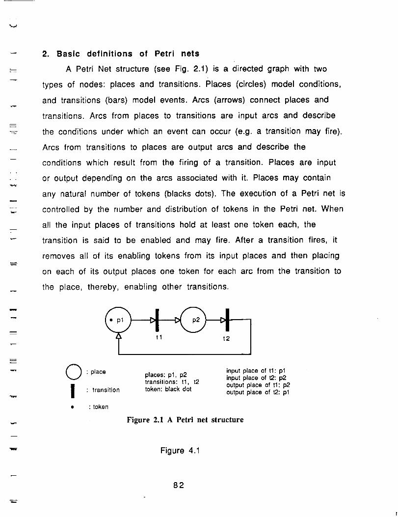
L__--___=--
=•
2. Basic definitions of Petri nets
A Petri Net structure (see Fig. 2.1) is a directed graph with two
types of nodes: places and transitions. Places (circles) model conditions,
and transitions (bars) model events. Arcs (arrows) connect places and
transitions. Arcs from places to transitions are input arcs and describe
the conditions under which an event can occur (e.g. a transition may fire).
Arcs from transitions to places are output arcs and describe the
conditions which result from the firing of a transition. Places are input
or output depending on the arcs associated with it. Places may contain
any natural number of tokens (blacks dots). The execution of a Petri net is
controlled by the number and distribution of tokens in the Petri net. When
all the input places of transitions hold at least one token each, the
transition is said to be enabled and may fire. After a transition fires, it
removes all of its enabling tokens from its input places and then placing
on each of its output places one token for each arc from the transition to
the place, thereby, enabling other transitions.
Q • place
_ • transition
• • token
places: pl, p2transitions: tl, t2token: black dot
input place of tl: plinput place of t2:p2
output place of tl: p2output place of t2: pl
Figure 2.1 A Petri net structure
Figure 4.1
82
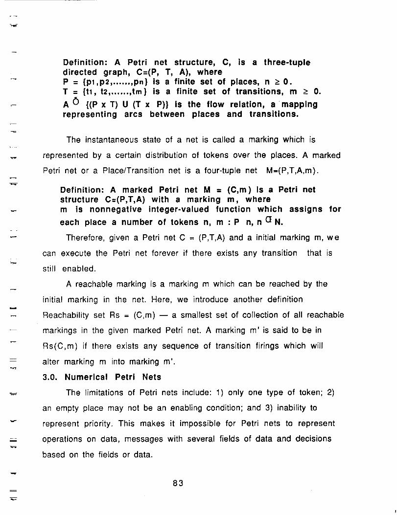
u
mm
E
Definition: A Petri net structure, C, is a three-tuple
directed graph, C=(P, T, A), whereP = {pl,p2, ...... ,pn} is a finite set of places, n _> 0.
T = {tl, t2, ...... ,tin} is a finite set of transitions, m _> 0.
A 0 {(p x T) U (T x P)} is the flow relation, a mapping
representing arcs between places and transitions.
The instantaneous state of a net is called a marking which is
represented by a certain distribution of tokens over the places. A marked
Petri net or a Place/Transition net is a four-tuple net M--(P,T,A,m).
Definition: A marked Petri net M = (C,m)is a Petri net
structure C=(P,T,A) with a marking m, wherem is nonnegative integer-valued function which assigns for
each place a number of tokens n, m :P n, n aN.
Therefore, given a Petri net C = (P,T,A) and a initial marking m, we
can execute the Petri net forever if there exists any transition that is
still enabled.
A reachable marking is a marking m which can be reached by the
initial marking in the net. Here, we introduce another definition
Reachability set Rs = (C,m) m a smallest set of collection of all reachable
markings in the given marked Petri net. A marking m' is said to be in
Rs(C,m) if there exists any sequence of transition firings which will
alter marking m into marking m'
3.0. Numerical Petri Nets
The limitations of Petri nets include: 1) only one type of token; 2)
an empty place may not be an enabling condition; and 3) inability to
represent priority. This makes it impossible for Petri nets to represent
operations on data, messages with several fields of data and decisions
based on the fields or data.
w
83
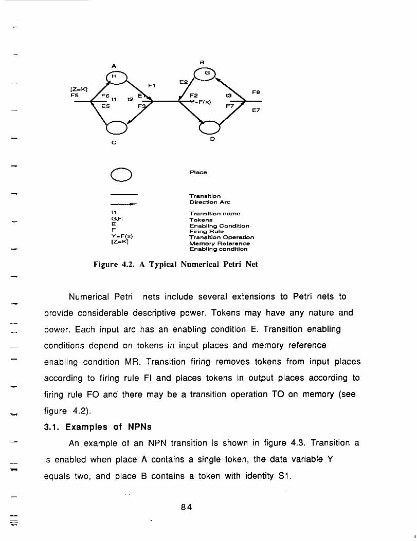
BA
[Z=Kl
F5
C D
Place
Transition
Direction Arc
tl Transition name
G,I-; Tokens
E Enabling ConditionF Firing Rule
Y--F(x) Transition Operation
[Z=K] Memory ReferenceEnabling condition
Figure 4.2. A Typical Numerical Petri Net
m
Numerical Petri nets include several extensions to Petri nets to
provide considerable descriptive power. Tokens may have any nature and
power. Each input arc has an enabling condition E. Transition enabling
conditions depend on tokens in input places and memory reference
enabling condition MR. Transition firing removes tokens from input places
according to firing rule FI and places tokens in output places according to
firing rule FO and there may be a transition operation TO on memory (see
figure 4.2).
3.1. Examples of NPNs
An example of an NPN transition is shown in figure 4.3. Transition a
is enabled when place A contains a single token, the data variable Y
equals two, and place B contains a token with identity Sl.
i
=
84
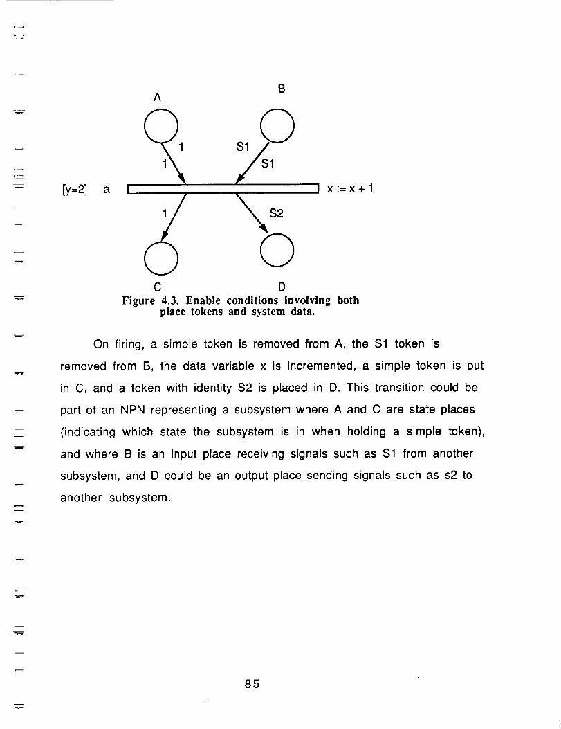
.--
m
m
m
v
BA
[y=2] a I I x:=x+l
1
QC D
Figure 4.3. Enable conditions involving bothplace tokens and system data.
On firing, a simple token is removed from A, the $1 token is
removed from B, the data variable x is incremented, a simple token is put
in C, and a token with identity $2 is placed in D. This transition could be
part of an NPN representing a subsystem where A and C are state places
(indicating which state the subsystem is in when holding a simple token),
and where B is an input place receiving signals such as $1 from another
subsystem, and D could be an output place sending signals such as s2 to
another subsystem.
85
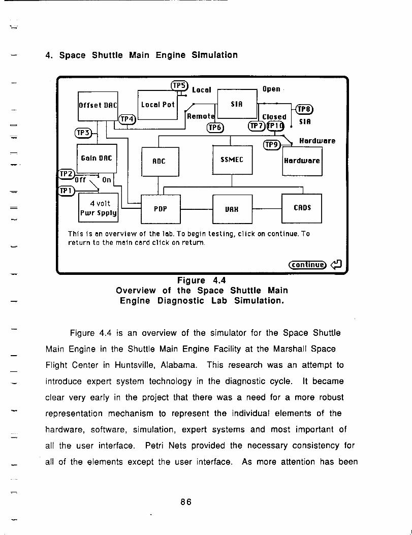
4. Space Shuttle Main Engine Simulation
w
m
i
Local
Local Pot __
SIA
SSMEC Hardware
VAX CADS
This is an overview of the lab.To begin testing,click on continue.Toreturn to the main card click on return.
Figure 4.4
Overview of the Space
Engine Diagnostic Lab
(continue) (_)
Shuttle Main
Simulation.
m
Figure 4.4 is an overview of the simulator for the Space Shuttle
Main Engine in the Shuttle Main Engine Facility at the Marshall Space
Flight Center in Huntsville, Alabama. This research was an attempt to
introduce expert system technology in the diagnostic cycle. It became
clear very early in the project that there was a need for a more robust
representation mechanism to represent the individual elements of the
hardware, software, simulation, expert systems and most important of
all the user interface. Petri Nets provided the necessary consistency for
all of the elements except the user interface. As more attention has been
86
m
focused on hypermedia it was determined that petri nets provided an
excellent underlying foundation for the representation of the user
interface. In figure 4.5 the interesting points in the simulation are
represented by buttons in Hypercard. As the simulation is run the figure
4.4 will be animated in a separate window so that the user can see the
results evolve in the SSME Overview as well as watch the animated
diagnostics window where the actual knowledge base is running. Figure
4.5 is an example of this simulation.
w
B
87
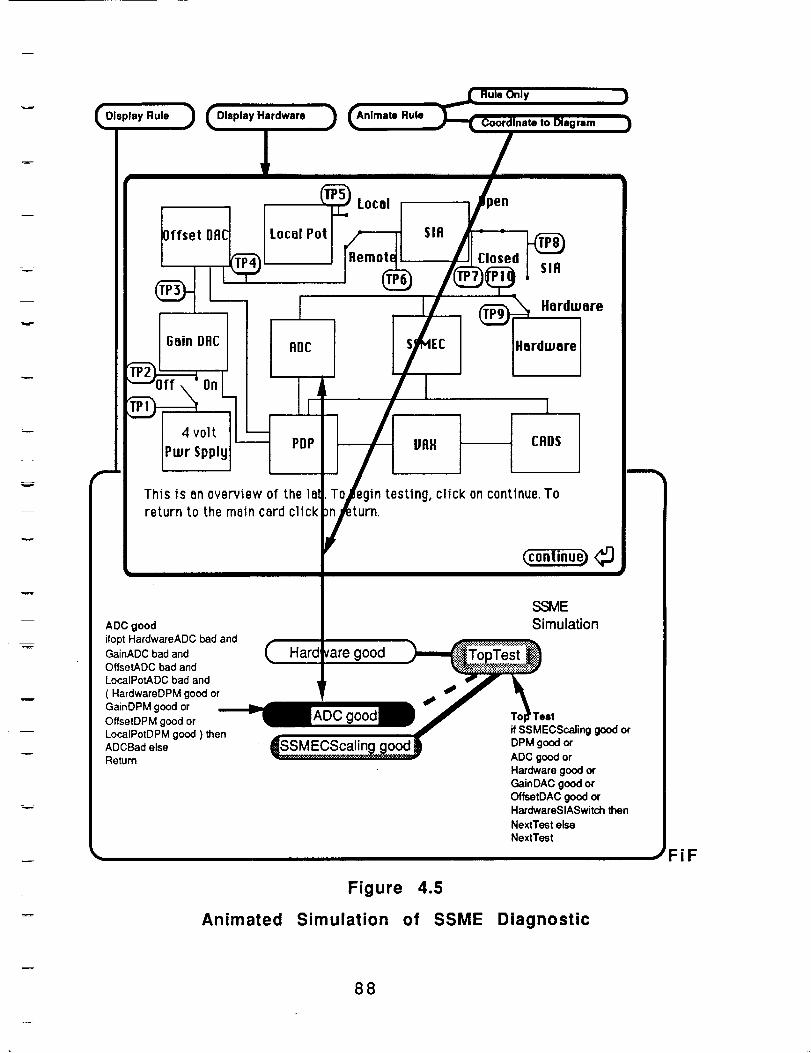
Rule , Hardware RuleDiegmm
Offset DAC
I
Gain DAC
_ Local
Local Pot
ADCi
i
4volt ' mPDP
Pwr Spply
Thisisan overviewof thelal
returnto themain cardclick
• SIA
'Remote ,.,,,
® ""L_ ' _are
Hardware
i
VAX CADS
oZT n testing, click oncontinue. To
I
(continue) <_
ADC goodifopt HardwareADC bad andGaInADC bad andOffsetADC bad andLocalPotADC bad and
( HardwareDPM good orGainDPM good or
OffsetDPM good orLocalPotDPM good ) thenADCBad elseReturn
SSMESimulation
va,e0oo To_ Teelif SSMECScaling good or
ti_ DPM_o_orADC good orHardware good orGainDAC good orOffsetDAC good orHardwareSIASwitch thenNextTest elseNextTest
Figure 4.5
Animated Simulation of SSME Diagnostic
FiF
88
R
The top part of the diagram is the overview of the SSME Diagnostic
Simulation. The bottom part of the window shows the structure of the
knowledge base. The black background with the dashed line leading into
it is the current section of the system being simulated. The simulator
allows several options - Display just the rule, display just the hardware,
animate the rules, animate the hardware, and most important animate the
coordination between rule base and diagram. This allows the user to
introduce spatial reasoning into the sequence of actions in the diagnostic
simulation. 5. The present analysis problems for Petri nets for
the SSME Simulator
HNPN's offer another important alternative, and that is the
capability to do analysis on the net representation of the main engine
shuttle. One of the major Petri net analysis techniques is the
reachability tree. In order to evaluate the usefulness of this analysis
technique, we first need to consider what types of problems may require
Petri nets.
4.1. Safeness
For a Petri net, a place is said to be safe if the number of tokens in
that place never exceed one. Thus a Petri net is said to be safe if all
places in the net are safe, which means the tokens in all places are less
or equal to one for all possible markings which derived from the initial
marking in a net [PET81][REI85][LIE76]. The formal definition is:
Definition: A Petri net C = (P,T,A) with an initial marking m
is called safe iff, for all m a Rs (C,m)and all piaP, m(pi)<_1.
89
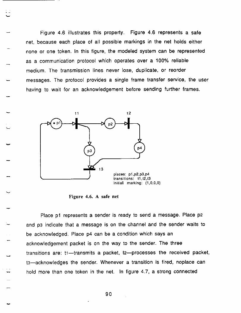
Figure 4.6 illustrates this property. Figure 4.6 represents a safe
net, because each place of all possible markings in the net holds either
none or one token. In this figure, the modeled system can be represented
as a communication protocol which operates over a 100% reliable
medium. The transmission lines never lose, duplicate, or reorder
messages. The protocol provides a single frame transfer service, the user
having to wait for an acknowledgement before sending further frames.
=_.._--
tl t2
,)
places: pl,p2,p3,p4transitions: tl,t2,t3initiali marking: (1,0,0,0)
Figure 4.6. A safe net
Place pl represents a sender is ready to send a message. Place p2
and p3 indicate that a message is on the channel and the sender waits to
be acknowledged. Place p4 can be a condition which says an
acknowledgement packet is on the way to the sender. The three
transitions are: tl--transmits a packet, t2--processes the received packet,
t3--acknowledges the sender. Whenever a transition is fired, noplace can
hold more than one token in the net. In figure 4.7, a strong connected
90
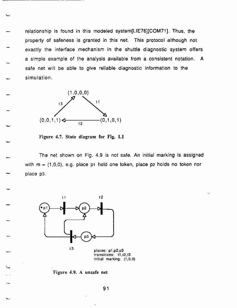
relationship is found in this modeled system[LIE76][COM71]. Thus, the
property of safeness is granted in this net. This protocol although not
exactly the interface mechanism in the shuttle diagnostic system offers
a simple example of the analysis available from a consistent notation. A
safe net will be able to give reliable diagnostic information to the
simulation.
(1 ,o,o,o)
t,/Z(0,0,1,1)_ (0,1,0,1)
t2
Figure 4.7. State diagram for Fig. 1.1
The net shown on Fig. 4.9 is not safe. An initial marking is assigned
with m = (1,0,0), e.g. place pl hold one token, place p2 holds no token nor
place p3.
tl t2
t 3 places: pl,p2,p3transitions: tl,t2,t3
initial marking: (1,0,0)
Figure 4.9. A unsafe net
91
L .
w
.. J,-.
From the above figure, firing an enabled transition tl in the initial
marking produces a new marking m' = (0,1,0). In this new marking, we can
fire any new enabled transition, say tk (in this case, t2 is the only choice
left), resulting in a new marking m" = (0,0,1). This can be continued as
long as there is at least one enabled transition in one of the markings.
Firing this particular net, a marking with the firing sequence _ = tl-t2-
t3-tl shows that the distribution of tokens on place p2 is greater than 1.
Therefore, by definition, the Petri net on Fig. 4.9 cannot said to be a safe
net.
5.2. Boundedness
In many cases, some modeled systems are not necessary to require
safeness. Instead it is important to ensure another property in the net
which is k-bounded or k-safe. A place is said to be k-bounded if the
number of tokens in that place is never greater than an integer k.
Therefore, if a net with an initial marking is k-bounded in all places in
each possible marking never exceed a certain maximum number k.
Definition: A Petri net C= (P,T,A) with an initial marking m
is called k-safe iff, for all m' G Rs (C,m) and all pl C_ p,
m (pi) _< k.
A data structure type operation "stack" problem illustrates this
property (see Fig. 4.10). There are two places and two transitions in the
net. Place pl represents the capacity of a stack (e.g., slots available in
the stack) and place p2 represents a user. The user may access the stack
through two operations - push and pop. Transition tl indicates a pop
operation, where the user can access whatever is inside the top of the
92
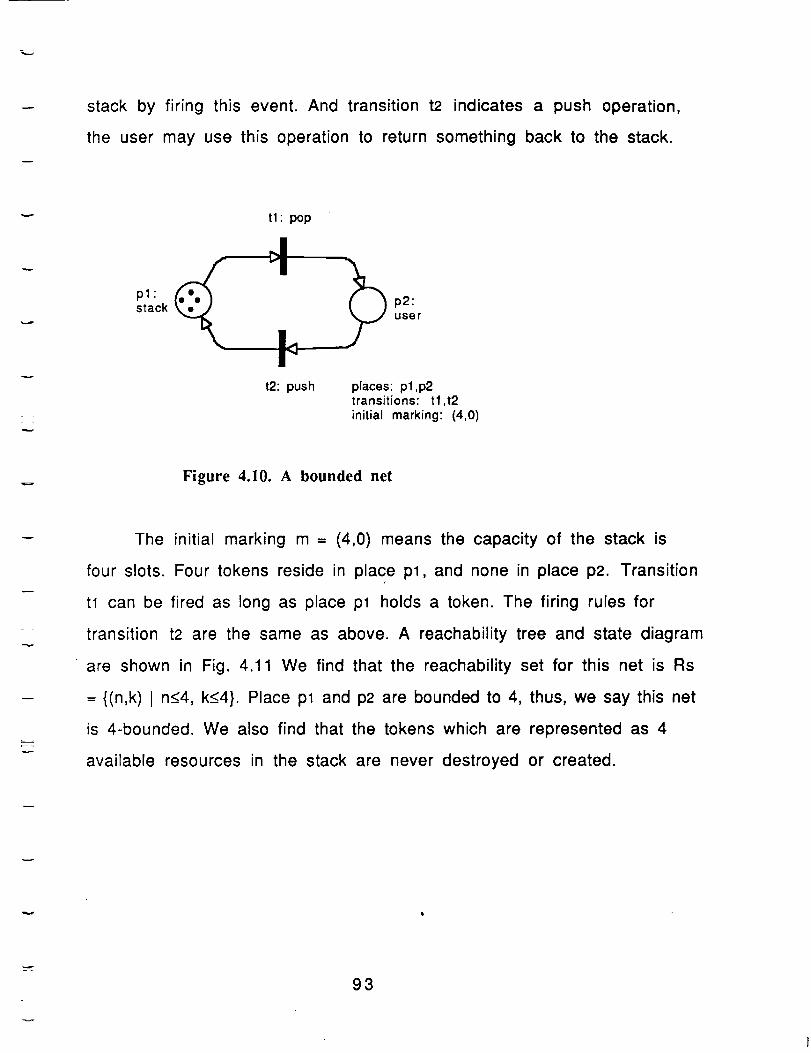
stack by firing this event. And transition t2 indicates a push operation,
the user may use this operation to return something back to the stack.
tl" pop
pl"stack p2:
user
t2: push places: pl,p2transitions: tl,t2initial marking: (4,0)
Figure 4.10. A bounded net
The initial marking m = (4,0) means the capacity of the stack is
four slots. Four tokens reside in place pl, and none in place p2. Transition
tl can be fired as long as place pl holds a token. The firing rules for
transition t2 are the same as above. A reachability tree and state diagram
are shown in Fig. 4.11 We find that the reachability set for this net is Rs
-- {(n,k) I n<4, k<4}. Place pl and p2 are bounded to 4, thus, we say this net
is 4-bounded. We also find that the tokens which are represented as 4
available resources in the stack are never destroyed or created.
93
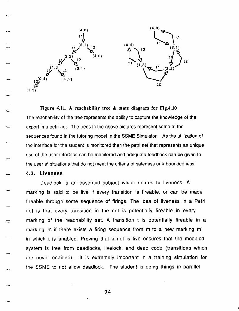
(4,0) (4,0)
(3, 1_2 (0,4) (3,1)
(2,2_ 2 (4,0)_/ tl (1,3) ,, t2
_1'3,_ (31)2 ' _#_,2)
t_,0,4) (2,2) t2
(1,3)
v
Figure 4.11. A teachability tree & state diagram for Fig.4.10
The reachability of the tree represents the ability to capture the knowledge of the
expert in a petri net. The trees in the above pictures represent some of the
sequences found in the tutoring model in the SSME Simulator. As the utilization of
the interface for the student is monitored then the petri net that represents an unique
use of the user interface can be monitored and adequate feedback can be given to
the user at situations that do not meet the criteria of safeness or k-boundedness.
4.3. Liveness
Deadlock is an essential subject which relates to liveness. A
marking is said to be live if every transition is fireable, or can be made
fireable through some sequence of firings. The idea of liveness in a Petri
net is that every transition in the net is potentially fireable in every
marking of the reachability set. A transition t is potentially fireable in a
marking m if there exists a firing sequence from m to a new marking m'
in which t is enabled. Proving that a net is live ensures that the modeled
system is free from deadlocks, livelock, and dead code (transitions which
are never enabled). It is extremely important in a training simulation for
the SSME to not allow deadlock. The student is doing things in parallel
94
with activites distributed throughout the simulator. It is essential that
nothing in the student interface cause deadlock. All nets must be live.
Summary
Applying ITS technology to the shuttle diagnostics would not
require the rigor of the Petri Net representation, however it is important
in providing the animated simulated portion of the interface and the
demands placed on the system to support the training aspects to have a
homogeneous and consistent underlying knowledge representation. By
keeping the diagnostic rule base, the hardware description, the software
description, user profiles, desiered behavioral knowledge and the user
interface in the same notation, it is possible to reason about the all of
the properties of petri nets, on any selected portion of the simulation.
This reasoning provides foundation for utilization of intelligent tutoring
systems technology.
z
95