a lightweight, 64 -element, organic phased array with ... · array with integrated transmit-receive...
TRANSCRIPT

A Lightweight, 64-element, Organic Phased Array with Integrated Transmit-Receive SiGe
Circuitry in the X BandCarlos A. Donado Morcillo1,
C. Patterson1, T. K. Thrivikraman1, B. Lacroix1, B. Wilson2, B. Hudson2, C. T. Coen1, C. H. J. Poh1, T. Heath2,
J. D. Cressler1 and J. Papapolymerou1
1 School of ECE, Georgia Institute of Technology,2 Georgia Tech Research Institute (GTRI)
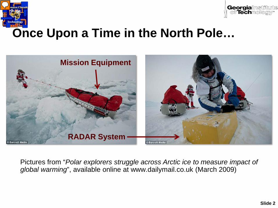
Once Upon a Time in the North Pole…
Slide 2
Mission Equipment
Pictures from “Polar explorers struggle across Arctic ice to measure impact of global warming”, available online at www.dailymail.co.uk (March 2009)
RADAR System

Near Future Goal (Concept)
Slide 3
Unmanned Air Vehicle with lightweight phased array for radar surveying
Source: nasa.gov
Survey Results: 3D model of the ice layerSource: National Geographic

The Purpose of this Work
Slide 4
To develop a high-performance, low-cost and lightweight transmit/receive (Tx/Rx) phased array for efficient unmanned ice-survey studies in X-band
X-band radar will be part of sensor suite
8-16 GHz (2006) 9.5 GHz(This Work)

– Multilayer Organic Technology– Embedding of Low Cost SiGe and RF MEMS Electronics– Back-end Electronics and Control Using FPGA Technology
3-D SOP Approach

Agenda
Slide 6
•SiGe RF Circuits•Phased Array Features•System Components•Performance Test Results•Conclusions

Phased Array Features
Slide 7
•Low energy consumption
•Lightweight•Low cost
Integrated High Performance
Transmit Receive
Operation
Computer DrivenBeam
Steering
Low Energy Consumption
Silicon Germanium Integrated
Circuits
Low Cost, LightweightSilicon-based
Circuitry (MEMS, Tx/Rx IC)
Organic Substrates
(LCP/Duroid)

Phased Array Design Radio Frequency Specifications
Slide 8
•Center Frequency 9.5 GHz•Target Bandwidth: >500 MHz•Equal-gain Beam Steering
Range: ± 26°•Transmit/Receive Capability

Slide 9
Radar Block Diagram
Radar Back End (Down/Up Conversion and Local Oscillators)
Control FPGA(for SiGe ps)
RFLayers
MEMST/R Switchchip
SiGe chip
DC Power Supply &Distribution Boards
Front End
Laptop for master control & processing
Beamformer
AntennasPhaseshifter
GT team is developing the entire radar system 1 SiGe+MEMS chip per arraycolumn (=8 antennas)
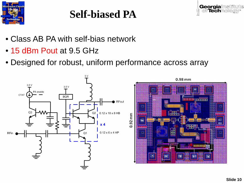
• Class AB PA with self-bias network• 15 dBm Pout at 9.5 GHz• Designed for robust, uniform performance across array
Self-biased PA
Slide 10

15 dBm Pout @ 9.5 GHzPAE = 30.7%
Peak Gain = 23.3 dB
Self-biased PA simulations
Slide 11

SiGe T/R Chips
IBM 8HP Process
Photo of the TR Module
Block Diagram TR Module
Integrated T/R LNA, PA, duplexer switchCMOS phase shifter, and digital logic
Slide 12

Layout of T/R Chip
Slide 13

Board Level Rx SiGe Characterization
Measured Rx path in the mounted on LCP/Duroid board
Measured Rx path on Chip Slide 14
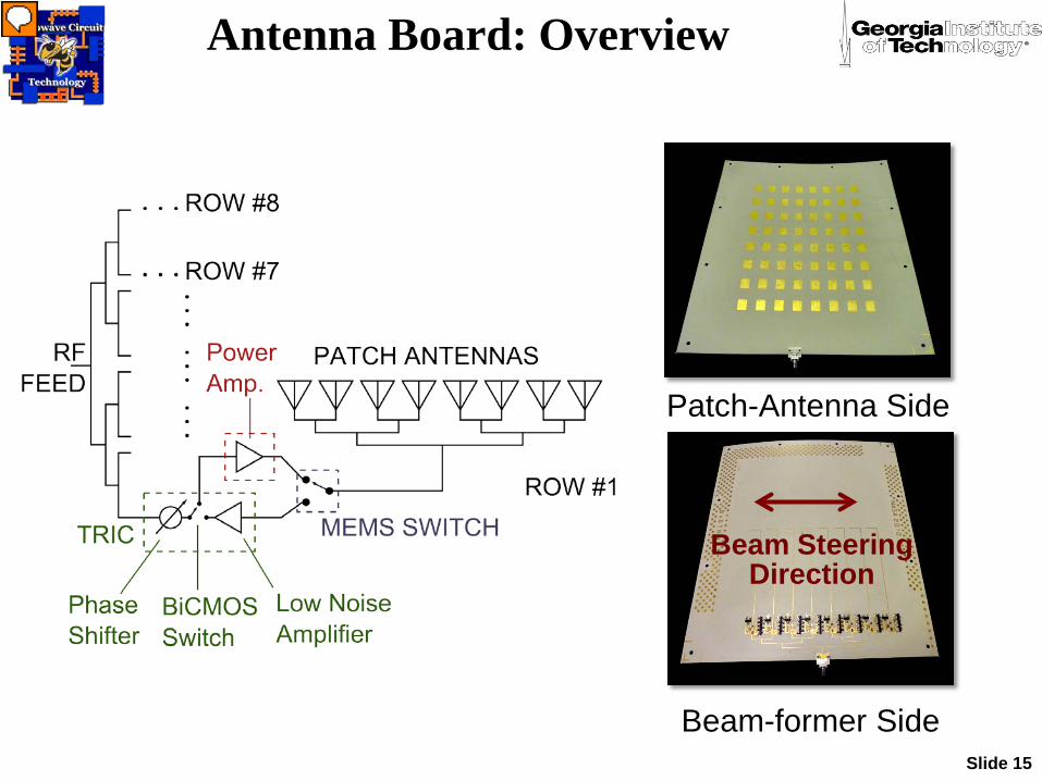
Antenna Board: Overview
Slide 15
Patch-Antenna Side
Beam-former Side
Beam SteeringDirection
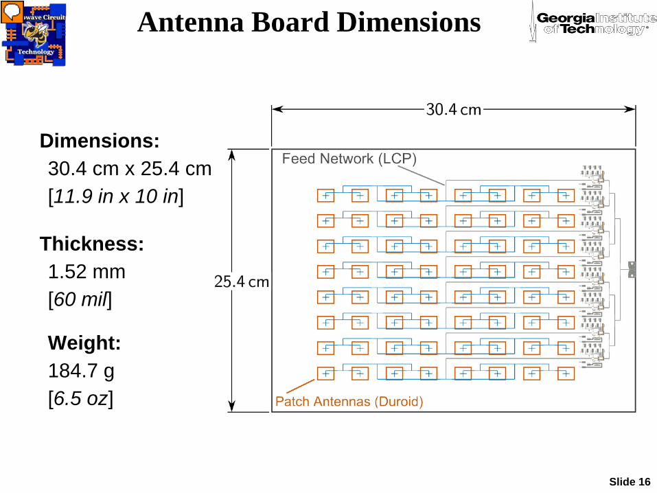
Antenna Board Dimensions
Slide 16
Dimensions:30.4 cm x 25.4 cm[11.9 in x 10 in]
Thickness:1.52 mm [60 mil]
Weight:184.7 g [6.5 oz]

Antenna Board: Substrate Stackup
Slide 17
• Beam former: Rogers 3850 Liquid Crystal Polymer (LCP)
• Patch Antenna Substrate: RT/Duroid 5880 LZ
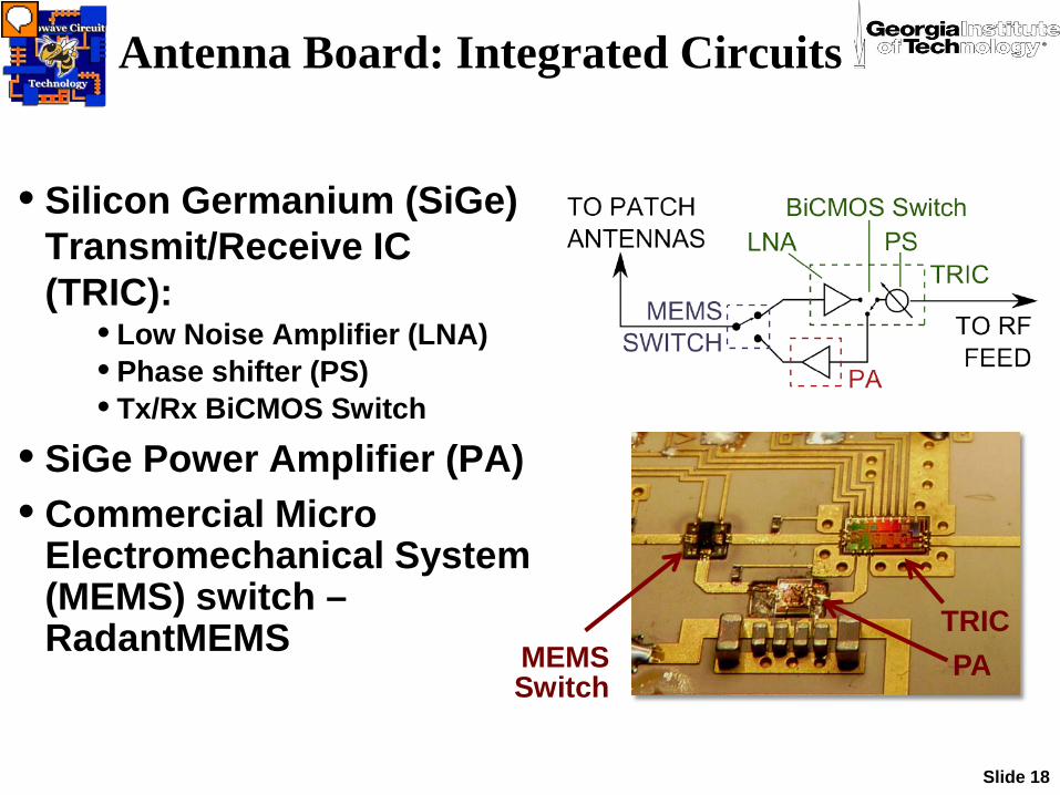
Antenna Board: Integrated Circuits
Slide 18
• Silicon Germanium (SiGe) Transmit/Receive IC (TRIC):
• Low Noise Amplifier (LNA)• Phase shifter (PS)• Tx/Rx BiCMOS Switch
• SiGe Power Amplifier (PA)• Commercial Micro
Electromechanical System (MEMS) switch –RadantMEMS MEMS
Switch
TRICPA

Digital Control and Power Supplies
Slide 19
• Power Supply Module- 2.5 V for antenna-board logic- 3.5 V for RF circuitry- 5.0 V for MEMS Driver Card
• Digital Control- Field Programmable Gate
Array (FPGA) controls RF- Computer program: human
interface for FPGA
• Additional power supply for MEMS actuation (80 V)
PA ControlBoard
SiGe ControlBoard

Performance Test: Measurement Setup
Slide 20
DC/DigitalModule
LaptopMEMS Power Supply
Antenna Board
Fully Automated Anechoic Chamber
Antenna Board Mount
Slide 21
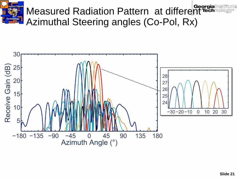
Measured Radiation Pattern at different Azimuthal Steering angles (Co-Pol, Rx)

Slide 22
Measured Radiation Pattern at different Azimuthal Steering angles (Co-Pol, Tx)
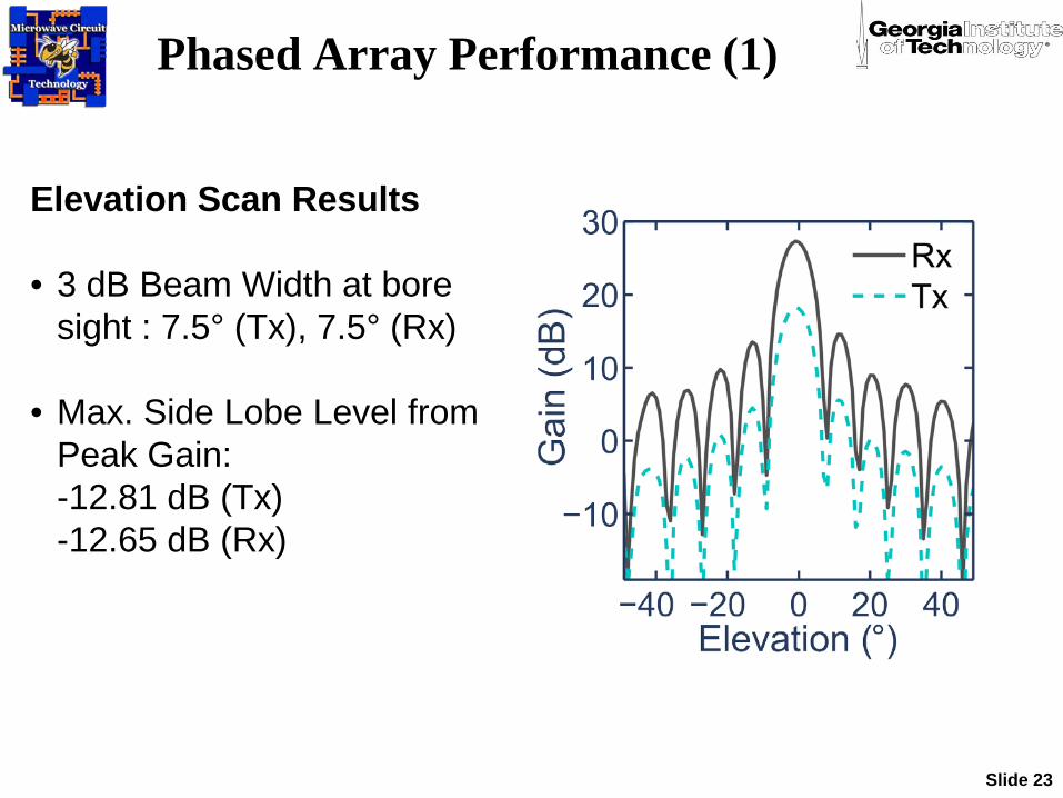
Phased Array Performance (1)
Slide 23
Elevation Scan Results
• 3 dB Beam Width at bore sight : 7.5° (Tx), 7.5° (Rx)
• Max. Side Lobe Level from Peak Gain:-12.81 dB (Tx)-12.65 dB (Rx)

Phased Array Performance (2)
Slide 24
• Antenna bandwidth: 2.430 GHz (Rx)2.625 GHz (Tx)2.52 GHz (Average)
• Bore sight gain at 9.5 GHz: 27.28 dB (Rx) 18.24 dB (Tx)

Slide 25
Parameter Measured (Rx) Measured (Tx)Bandwidth 2.430 GHz 2.625 GHzBeam-Steering Range ± 28.0° ± 28°
Energy Consumption 601.3 mW
Max. Cross-Polarization level <30 dB <30 dB
Estimated EIRP -- 41.33 dBm
Phased Array Performance (3)
Slide 26
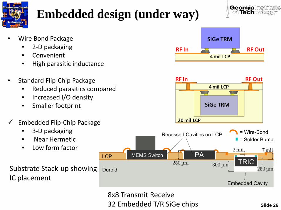
8x8 Transmit Receive 32 Embedded T/R SiGe chips
Substrate Stack-up showing IC placement
Embedded design (under way)
• Wire Bond Package• 2-D packaging• Convenient• High parasitic inductance
• Standard Flip-Chip Package• Reduced parasitics compared• Increased I/O density• Smaller footprint
Embedded Flip-Chip Package• 3-D packaging• Near Hermetic• Low form factor
Slide 27
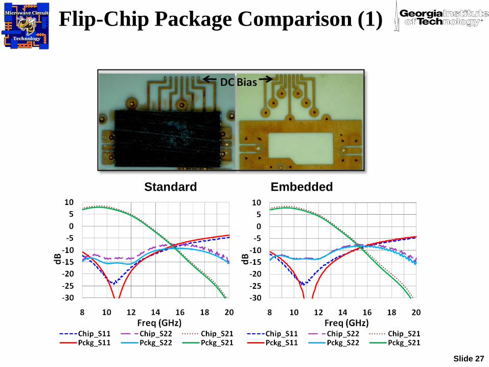
Flip-Chip Package Comparison (1)
Standard Embedded
Slide 28
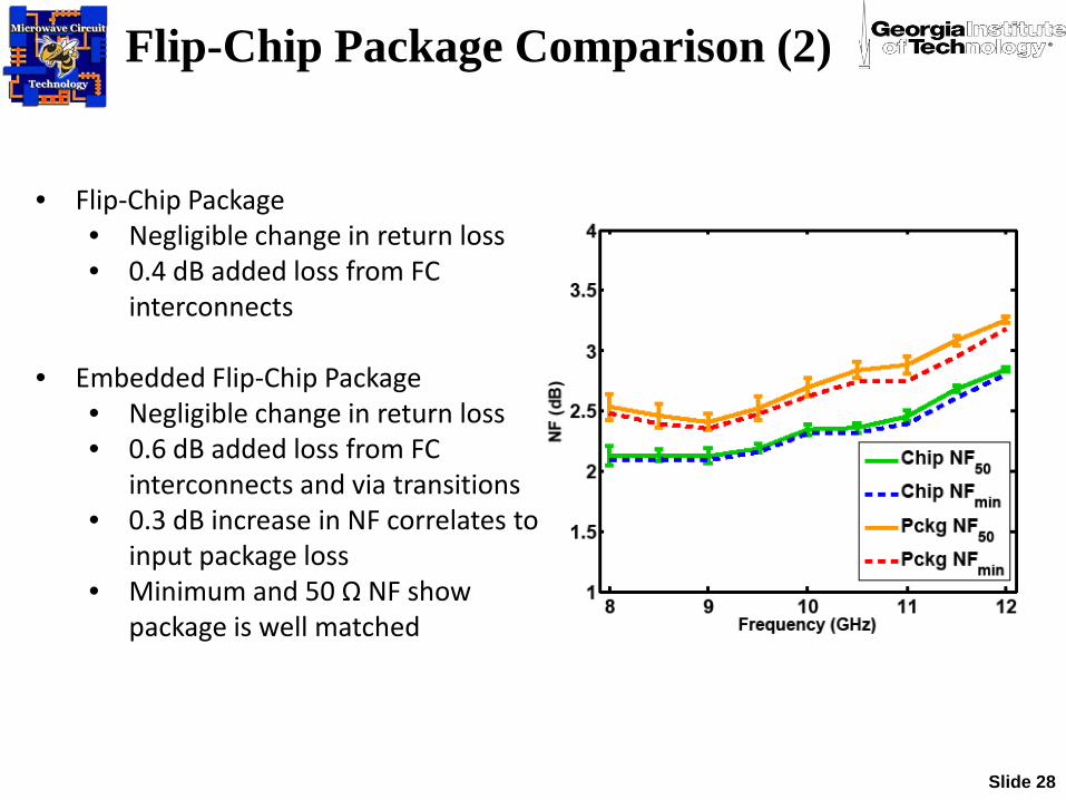
• Flip-Chip Package• Negligible change in return loss• 0.4 dB added loss from FC
interconnects
• Embedded Flip-Chip Package• Negligible change in return loss• 0.6 dB added loss from FC
interconnects and via transitions• 0.3 dB increase in NF correlates to
input package loss• Minimum and 50 Ω NF show
package is well matched
Flip-Chip Package Comparison (2)

RF Back-End Development
Tx Stage 1 Tx Stage 2
Rx Stage 2 Rx Stage 1Slide 29
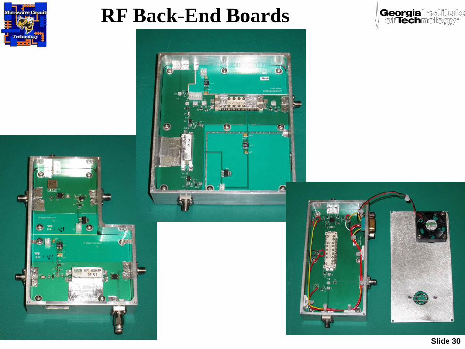
RF Back-End Boards
Slide 30

Summary
• The T/R operation of an organic 64-element phased array was demonstrated for the first time using SiGe ICs at 9.5 GHz.
• Measurements showed: - Rx gain of 27.28 dB- Tx gain of 18.24 dB- Beam Steering of 60 degrees- EIRP of 41.33 dBm
• Further research will focus in bringing SiGe ICs closer to the patch antennas through innovative Packaging Techniques
Slide 31

Thank You
Slide 32
Questions?