a study on hull structures for ageing · pdf file(5) result of the condition survey (survey...
TRANSCRIPT

“1,
.-
THE SOCIETV OF NAVAL ARCHITECTS AND MARINE ENGINEERS601 Pevonla Avenue, Suite 400, J-Y CltY,NW Jersey ~ USA
Psper prasanti at the Ma!irn 5trwaIIA lnaprciio~, Maintiance, smd MonitoringSynrWiumShsratonNaibrad H*1, Adingtnn,ViWinia, March 1519, lW1
A Study on Hull Structures for Ageing Ships. A basic study on life assessment of “shipsand offshore structures
H. Emi, A. Kumano and N. Baba, ResearchInstitute,NipponKaijiKyokai,Tokyo,JapanT. hoandY. Nakamura, HeadOffice,NipponKaijiKyokai,Tokyo,Japan
ABSTRACT
In order to extend a life of ageing ships, it is necessary to be
made a studyon feasibilityforextendingplannedlife.The feasi-
bility study consists of a life assessment with a conditionsurvey/assessment, .a life prediction technique and an availability
assessment, We (Nippon Kaiji Kyokai : NK, a classification
society) have made a basic study for developing a life ~sessmentsystem of ships and offshore structures. The logic of procedures
for the life assessment is shown diagrammatically in the paper.
Hull integrities for life extension having conventional structures.
will be examined by an empirical method if the structures =e
well protected from corrosion. However, hnl.1 structures with
the greater use Qf high terde steels have no experience used for
a long life exceeding 15 to 20 years as they me of a new generw
tion. Therefore, at a Me extension for such a ship, special c=e
shall be piid for its fatigue strength as well x protecting corr~
sions. In the paper, studies on fatigue strength for hull structure
with mild and high tensile steels and maintenance procedures for
well protecting corrosion are briefly reviewed. And a discussion is
made to a procedure of an assessment for life extension of ageing
Ships.
I. INTRODUCTION
In order to extend a Life of ageing ships, it is necessary to bemade a safety assessment for extending planned life. The safetyassessment is of course carried out in accordmce with theminimum requirements by clawitication smiet y’s rules. NK (Nip-pon Kaiji Kyokai : a classification society) has also specified
such requirements by the rules and has developed in 1989 a spe-cial statrdard of-condition surveys on hull structures for ageing
ships.1)
A feasibility y study of. the Me extension is generally carried
out as the shippi,rtg companies concerned likes. However, a pre-
cise and rational feasibility study may be required by the parties
widely concerned for “a specially high grade ship, such as LNG
cwriers. The ratiort~ feasibility study shall consist of a life
assessment with a condition survey/assessment, a life prediction
technique and an availability assessment. The assessments may
be carried” out” by a joint” study cooperated the shipowners oroperators and tec~ical bodies e,g, shipyards/desig-ncrs, classirl-
cation sotieties, authorities of the assessments etc. We have
made a basic study for developing a rational life ~sessment sys-
tem of ships and off-shore structures. The logic of the procedures
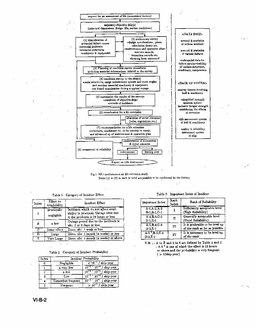
for the assessment is shown diagrammatically in Fig.1. A highgrade ship operated with a good maintenance policy is a main
objective of this study, but the result of this study can be also
applicable to any ships ad off-shore structures.
The paper summaries the results of the basic study and
describes a strategy and method for ~sessing a pkrnerl life with
a high reliability similar to the past one of the subjected ship(s).
2. LIFE ASSESSMENT METHOD ANDBACKUP SYSTEM
,2.1. Procedures of the Lffe Assessment
The ~~procedures shown in Fig.1include both of
economical/social and technkal problems to be considered at theass&msent. The forrmrs are mainly considered by shipping com-
panies concerned etc., while the laters are considered by the
shipping cornpties with rm assistance of tecti!cal parties such
w sKlpyrcrds/designers, classification societies. Nos. with a
parenthesis ( ) in Fig.1 show the technical problems involved
the perties, and their details are as follows ;
(1) Identification of potential failure causes
Potential failure causes which may result in signfi- ,
crmt nnplarmed ship outages differ depending upon the “ ,
ship’s kinds, construction and equipment, machinery ad
many other items. At the first stage, potential failure
causes to be considered for the assessment are clarbied and
identtied in each case es per the subjected ships and the
life extending Plans which are given at requests, A concept
for identifying the potential failure causes is- proposed in
2.2.1. It is necessary to provide data bases such as shownin Fig. 1 for revealing the potential failure causes.
(2) Preliminary survey
The preliminmy survey prior to the conditionsurvey/assessment is of literature surveys on documents
and hearings from the concerns. The following documents
are gathered and surveyed ;
(a) Terms of design and construction of the ships ; speciri-
catiorq drawings, calculation sheets, test results and so
on of the main hull structures, cargo containment sys-tems, proptilve and other’s essential machinery and
equipment
(b) Plans of operation and maintenance ; instructions,manuals etc.
(c) Service records ; operational records, survey reports,
mairttemmce & repair records, faihtre/incidents recordsetc.
(3) Planning of condition survey procedures
Accordhtg to the preliminary survey, prmedures ofthe condition survey are planned and fied with the parties
concerned, Ii this planning, essential information for thepotential failure causes are also given from the data bases
and back up systersm. The plan clearly shows ;
(a) Criteria to be aases6ed ; i.e. Identtication of potential
failure causes to be ssesse~ x prescribed in (1)
(b) Ship(s) to be survey and duration(s) of the survey(s).
(c) Structure., machinery and equipment to be surveyed,
their conditions at the surveys including inspection
methods and persons in charge.
(d) Report form of the condition survey
(4) Condition sWvey
A format of the condition survey is proposed in 2.4.
7’- ...
VI-B-I
+=====
rcqnedforan assessmento[life(ecanomicalf actors)
(principal dimensions, dcsi~ Xfc,mcvickconditionk]
(1) identification of (2) prclimhmrycurvey
potential failurecauses— ●dc6ign specfication$ , plans,
,.. aemential incident6 calculation sheets etc.
*essential structures *mahtenancc and operation plan6
m~hinery & ●quipment— ●mrvice records,
“ inspection records ttc*hearing from concerned
W(3) Plmming of condition survey proceduresimcludmg csscn tial ihformations related to the survey
(4) condition mrvey to the ,hip(s)*main structure, cargo containment systemand main engine
andanother essentialmachinery & eauipment
E!zzzz=*on board examinationduringa typical voyage
(5) Summarizethe reKultsof the mrveys
—
E5ziEa(6) examination for a life extension
(7) recormnrndation for a life extension
●structures, machinery etc. to bc renewal or repair,and advanced UPof maintenance & operation plan I
<DATA BASE>
*record & Etatir4icsof scrions accident
*record & statistimof various failures
●refercncial data forfailure rate/probti]lity6f variaus.structure+,
mmhincry, components
<BACK UP SYSTEM>
*curvey format involvinghull & mdtinery
*simplMed Etrengthanalysis 6y6tem
inclusive fatigue ctrengthcomidcring the effects
of corrosion
●life -aessment systcmof hull & machinery
●safety & reliabfity=scssmrn t system
or ship
Fig. 1 NK’s per[ommnce on life extension studyItems (1) to (8) in each or total are possible to be conducted by the Society
Table 1 Category.of Incident Effect
IndexEffect to
AvailabtityIncident Effect
practically Incidents which do not affect avail-
A ability in practical Outage-time duenegligible
ti the incidents is 24 hours or less,
BOutage period due to the incidents is
a fewabt. 2 or 3 days or less.
~.Some effect Ditto, abt. 1 week or less
D ,Large Ditto, abt, 1 month (4 weeks) or less
E Very Large Ditto, abt, 1 month (4 weeks) or above
Table 2 ‘Category of Incident Probabfity
Index Incident Probability
o Negligible 1 < 10-5/ shipyem
1 a very few~o_5 .
10-4 / shipyear
D-3 / ship-year,
t-l3 Low
~o_3 -10-J / ship-year
D-l / shipyear
1‘ ,’ hip-year,
121 a few I 10-’ “ 11
4 Somewhat frequent 10-’- lC
5 Freauen t > 10-4 / s!
Table 3 Important Index of Incident
Important IidexRankIndex
Rank of Reliability
A-1.A-2.A-3 . Sufkiently =ceptable level
D-3,E2Iv
of the rauk I
N.B. ; - A to E and O to 5 are defined by Table 1 and 2
- A.5 ● is one of which the dfect is 12 hours
or above and the probabtity is very frequent
( > l/stip-year)
I VI-B-2
.-. ...
,....- .,,
,.
(5) Result of the condition survey (Survey report)The report summarizes the results of the survey, SUdr
M (a) condition of the ship(s) .(defects, corrosion, ..wears
aid tears, deformation etc. of the structures, mrdinerysnd equipment) and (b) records -of essential incidents(kinds, extents and effects, causes, statistics), and (c)
essential comments to the result of the condition survey.
(6) Examination for life extension
The results of the condition survey are to be exsrn-irred, and if necessary the stress analyses, fatigue strength
(i
analyses considering effects of corrosion, ageing propertytests of non-metallic materiak”etc. shall be carrie”d out.
Recommendation for a planned ~fe extension
Accordirlg. to the. condition survey/assessment,
recommendations for a planned life extension shall be madeto the applicants, For examples, structures, machinery
.md equipment to be renewrd or fepair, advanced up of
maintenance and operation plans. Special attention is to be
paid for preventing corrosion of the hull structures.
(8) Assessment of safety and reliability
The ship’s reliability. i.e. availability for the planned
life extension wll be usessed irr accordance with a sys-
tematic procedures. A proposal of such a procedure is
described in 2.2:3.
2.2. A rroposal of Life Assessment System
2.2.1. Identification of Iucideut to beconsideredThereme manyincidentswhichcause to outages in ships,
rural many kinds of failures on structures, machinery and equip-
ment have r’isks resulted in such incidents. It is so complicated
but unremunerative for the result 01 the assessment to examine
all the risks. It is then rational that the survey/assessment is
carried out for essential structures etc. which may generate a
critical failures much affected the ship’s safety and availability.
Such structures etc. are revealed by a guidance with the
incidmts categorized as shown in Table 1,2 and 3. The incidents
categorized by these Tables sre consider~d to ones caused by
structural defects only, and incidents caused by outside factors
r. g. collisions, grouuclings are not taken irtto account because itseems that such incidents are occurred at random regardless of
the ship’s ages+
In general, it seems practi$al to the purposes that the incidentsto be surveyed/assessed are identified by the Category L-2, 1[ it
is preferable to be surveyed/assessed in more details, the rank IV
or LLI and IV shall be taken into account. This identification isdeternrimcdin discussions with the parties concerned.
2.2.2.IdentificationofStrictures, Mschiuery assd Equipment tobe surveyed/assessed
The structures, machinery and equipment to be
surveyed/=sessed are identified in accordance -with the concept
as described in 2.2.1. When we empirical y choose the essential
structures, machinery and equipment for the survey j~sessment,
examples are as follows ;
(a) hlain hull structures
(b) Cargo containment an! handling systems
(c) Propulsive machinery and others essential machinery &
equipment. .
Generally the items (a) and (b) can be es-sily identiLed, but
it is some of difficulties to identify the machinery and equip-
men t of the item (c) because there are may kinds of machinery
& equipment and their components-on the ship. Therefore con-
cept of the identtication as described in 2.2.1 and a life expected
(permanent, indeterminate or lintited life) of the machinery etc.
~ may be introduced for the assessment.If E-2 criteria is adopted, examples are w follows ;
(i) Sha[timgs of tke propulsion are considered as a permanent
life and Category D-2 or E-2 even if an extent use, and
they shall be carried out tke condition survey/assessment
al d subsequently be examined for the life assessment
(ii) Rudder is considered m be a permanent Me arrd Categm:,
~0 or BI even if an extent use as it has been well mair-
tairred in due course. and its condition survey /~sessment
only shall be carried out for the confirmation of its
integrity. A~ailability assessment of the rudder is not
necessary because unavailabtit )- due to an incident 01 this
Category is so”smalt.
(iii) Anchors and chain cables are of equipment having a lim-
i ted life and their condition rmrvey/=sessment shall be car-
ried out only for the confirmation or their rnaintenmce and
inspection procedures.
(iv)Main electric cables are considered M category D-2 or E2and they are of equipment with an indeterminate life. The
condition r.urvey/amessmen t aud examination for an extent
use including a test to demonstrate their integrities for the
extent use shall be carried out for the cables.
At the identification, consideration is to be paid for arressential [ailure even if it seems a minor one. e.g. a small crack of
an inner hull structure consisted of a supporting structure of
cargo containment systems with some types of liquefied gas car-
ries, or a small leak from fuel transfer pipes in engine rooms. The
former may cause a serious incident as like the insulations arewidely attacked by ballast waters. The later may cause a big
llre in the engine rooms.
Accordingly, a systematic risk analysis such as E,T.A,F,T,A etc. are carried out at the idcntfications of the essentialincidents and structures etc. At this stage, the analysis may be
of a briefly quantitative one so” that the incidents can be so
categorized as the Table 1, 2, and 3 and it is possible to be
snalyzed in comparatively less di~crrlty by an experimental
knowledge with sufficient and useful data buss.
2.2.3. AvailabiitJ. Assessmesrt
Purpose of the availability assessment in the Me assessment
is to provide evidence to demonstrate that the subjected ship(s)
will have an acceptable availability y over sn extending planned
life, and this acceptable availability is determined with reference
to that achieved in the past operation records. Availability (Av)
is given as follows ;
Au=l - fl (unavaila6iliiy 0/ u J/IIp)
u = ~s= + up~ + UOT
(1)
(2)
hence, U5Fis unavailability due to incidents caused by structural
defects. UpL is a planned unavailability e.g. regular docking,margins etc., ~-~T is unavailability due to incidents caused by
others isctors i.e. outiide factors smd prrre human errors during
operations, e.g. collisions, it seems that ~p~ is intentional but
indeterminable at the initial stage of the assessment snd UOT is
unchangeable to the ship’s ages. Then, L’5F only is considered in
the assessments.
MTTR,USF = XUSF, = ~ JfTTR. + ,IJTBF (3)
MTTR; is mem time repair or restore to the regular operation,MTl?F, is mean time betweert failure or incident = I/~t Suffix
“ i“ indicates a fzdure or incident “i” resulted in an outage 0[ thesiip. Ai is failure or incident rate per ship - year or day.
Acceptable or expective U5P is given by the planning of theof the life extension and as discussed in the above the pasteqeriences of the subjected ship and the sister ships are also
taken into account for its decision. Generally, Av, U, UfF etc.
are remarkably variable values because they depend on many
complicated factors.
Examples of unavailabilities caused by structural defects (
UsF ) are shown in Table 4, Unavailability caused by a design
and construction de[ect i.e. early failures is not considered for
the assessment 01 aged ships because such problems ought to
have been solved in the p=t. Acceptable or expective U~F may
be determined with reference to the past records and’ in con-
sideration of the above discussion.
VI-B-3

Table 4 Unavailability due to Structural defects ( U5F).
SfiipsU~F.per ship
Year/Year Days/YearRemadts “-
.“
: Two LNG carriers 0.035 12.a include causing design and ,corwtruction
(1964 - 1972)16.3 k.hip-year 0,014 5.1 exclude causing seemingly design & construction
11 LNG carriers..14,8.sllip-year
0.017 6.3 ditto
Two LNG carriers(.1969 w 1972) 0.024 8.8 ,,
ditto
7 ship-year
Wll plating’s opening 0.03 12.0MTTR=3 days “
,. (assumed)”fractur~ & crack I I .,
I I
,.
6000 cargo ships in 1989 0.01 3.6ditto ~~
exceu t corrosion I
,“ N.B., ; Tiie above is derived from @ references z),sj.q~, For the first two s~ips their r~gular dockiug.,
durations are assumed as 25 days/ship,year
~.. -Conclusi}.ely, ”the procedures of tile s-ssessment are summar-
ized as follows ;
(a)”’to determinecriteriaoftheassessmentby Table.1,2 and3.andacceptableorexpecthefJ~P
(b)to‘identfiytheessemt~afincident,/ failuresofthe,structures,etc.to be,surveyed/,assessedtakinginto account potential
failure causes, i,e. to put tllc “i” concretely.
(c) ,tonlaketheconditionsurveyfassessmentinaccordancewiththeprocedureswhicharefixed in advanced and if rrecesszuy,
to make recommendation to the. life extension.
(d) to predict MTl?F, ( = l/~~ ) in accordancewith the result ofthe condition survey/assessment and the subsequent eccani
,nations, involved , for, ageing effects tO the structures!machinery and equipment. The data base and back up SYS-
tern assist to this prediction.
(e] tO predict MTTRiwi~rreferetice-to kinds and extents of thefailures/incidents, operation plans and the
nmintenance/repairing programs of the ships
([) to predict U~F for the planned life extension.
(g) if U5F is acceptable with simultaneously taking into accountLrPL$he assessment wiU “be completed. If not, countermeas-
ures for decr~asing U5F will be examined and reconui~ended.,.
2.3. Dat* Base aud Back up System
NK has a sufficient knowledge and experience to carry out a
full or a part of the rational fire assessment in accordance with
the procedures’ shown in Fig. 1, Such a full assessment has how-ever a ‘big problem, i.e. the assessment accompanies- with exten-
si~,e works and it takes a long time to complete. To solve such a
problem as far as possible, it is preferable to prepare data bases
and. brick up system involved; [or assisting the assessment.
According to the ~~ic. study, it is concluded that the following
data bases and back up systems shall be developed for the
rational life ~sessmen ts. Sqme of. thOse are under deve~oping.
(1) Data bases
(a) Records’ and. statistics or accidents ; accidents of ships,
“oH-shore structur= and others.
(b)-.Faifure data ; data of failures of the essential structures,
: machinery, equipment “=d their components are to be
gathered. and so put iri order as probability y of the failures
can be predicted for the life assessment inclusive of ageing
e[fects.
(c) “Basic data for predicting incidents/failures effects ; data
and knowledge for predicting a time to repair or restore
$o’.the regular operations at a faihrre/incident,
(2) Back” tip syktem ‘
(a) Format of conditionshvey including preliminary survey.
(b) SirnpliGed malysis system to evafuate the hull strength
(rrftimate and fatigue) taking into account effects of cor-
,-.,.,,,, ,.
rosions and wears.
(c) cons~ti”g system to examine and evahrate a condition of
the essentiaf structures, machinery, equipment and their
components.
(d) Consulting system to tle ship’s. maqagiment system of
the maintenance for extending Me with a satisfactory cOn-
dition. ,- .,,. .,, ,
(e) Speciaf inspection techniques of the condition
survey/assessment for the life assessment.
(f)- Safety and” reliability assessment system of ships and off-
shore structures;
2.4. Conlfitiort Survey Format ~ “.
Condition survey k generafly csrried out fo> the purpose of
the ship condition assessment in ‘alf resPects” of hull structures,
machinery, electrical installations and equipnient in “order to
extend the’ life or a ship. In this survey, maintenance plans
including spare stocks of the materials, machirtery/equipmmtand their c“dmponents are afso’ importmt objectives to be exam-
ined.
Sur\ey records of the past class surveys can “provide the”concerned with necessary ‘information /data for “the prel.ir@nar~.,. ,.s~vey, e.g.;
(a) results .3{ exterrral/internal e:hlination of hutl structures
(b) results of thickness me=u~emen ts [or main hull structures
which ,are required at every Special Survey in Rules of this
Scciety, ,, , .’.,..., “,.
(c) results of hydrostatic tests or tanks
(d) results of external/overhaul examination of the. essentialmachinery, electrical installations and equipment
(e) restilts of” hydraulic/-pressure’ tests of pressure vessels kmachinery and equipmeht suck as boilers
‘U”preferable. information/data of sister skips” should betaken into consideration in the preliminary suirvey.
Results of the preliminary” survey def”rred h“ 2.1(2)” being
taken into consideration,, extmrt and procedures of condition sur-
vey are fixed in detaifs. Among many items of the condition sur-vey. the, respect of. assessment of corrosion in hull structures is
described hereinafter,” wllicl~ is the most essential in. this survey.
-.Tltis Society carI provide :the applicants with theprediction
of progress of cbirosion with .~sist arrce 0[ data bxe for this pur-
pose and advise them, how to maintsin the huff integrity for a
long time. ‘Accordingly, results of the condition survey of theexisting hulf structures are to be reported .as a rating of the fol- .
lowing five levels.
‘IcA” is excellent condition, -where no rusting and blistering
on paintti construction are observed, or. even if observed in a
very few areas,, no corrosion of hull structure members are
observed with paint coating in gooccondition..
.’
VI:B=4
--l
...- .,
‘VCB” is very good condition, where rusting on a little ofedge port rind/or w-elding”johit and on the” localized flat part ofhull structure members are observed, but little corrosion areobserved,
“cC” is good condition, where rusting on some edge parts,welding joints and flat parts of bull structure members are
observed. Blistering and pealing off parts of paint coating areobserved. Small numbers of pitting corrosion of hull structure
members are observed.
“cD” is good condition u far as the hull scantling, i.e, no
decre=e or the scantling is observed and small number of locafand pitting corrosion of hull structural members only are
observed, Pnint coating is partly pealed off in extensive areas.
,,CE,, is a ~olldition being in an advanced corrosionth~
“cD”level.Thisk acceptableconditionh a conventionsperiod-icalclasssurveyincludingsuchconditionsas to be requiredrepairworkstotheheavi]ycorrodedhull structures. Paint coat-
ing may be damaged in large areas including highly stressed
parts.
Definitionsof the hull conditions also include an intermedia-te level of the above, e.g. “cA/cEl, “cC/cJ3” etc.
It is delicate to write in a plain style about the hull condi-
tions of the rating levels. The society have then provide stand-
ardized colour pictures or the above levels in each location of the
hull structures. An expert involved such as the society’s sur-
veyors can discriminate the rating of the hull condition by the
above information.
The above distinctions have a trend to be somewhat precise
to the good conditions, where~ rough to the opposite conditionlevels. They are however rational to make an appropriate plan-
ning of the protecting corrosion as watching a progress ofdeterioration of the protecting effects.
In order to planning refurbishment of the hull structurw
themselves, it is necessary to divide “cE” level into more detail
such as “cLa” (corroded but acceptable), “c&f’ (reach to
acceptable limit), “cE-u” (unacceptable) etc, or to add a con-
crete description of the corroded conditions 01 ‘IcE”. Tl~e cor-
roded conditions are significantly variable in case by case, and it
seems that the later format is preferable in the condition survey.
kr case where condition survey is applied to the ships in“cEI’ level ;
(i) thickness measurements for all hull construction is required
in order to. nssess the distribution 01 hull corrosion.
(ii) sizes and distributions or heavy local corrosion. are to be
measured amd recorded..,
(iii) hydrostatic tests for tanks in which heavy corrosion are
observed are required to demonstrate their integrity.
Resufts of condition survey in the respect of corrosion reveal
not only the prediction of progress of corrosion of hull members
themsel~es but afso the prediction of deterioration of paint coat-
ing etc. The applicants can be adviced fiOm the Society on thecountermeasures for protecting corrosion. An example is shownin Table 5.
3. A STUDY ON CORROSION “OFHULL STRUCTURES
XI.InvestigationofHnLl Conditions
Extensive investigation of hull conditions has been carried
out for 48 ships of 5000 gross tonnage or above at their Special
Suri.ey or others in dockings in line of the categories of hulf con-
ditions introduced in 2.4. Surveyors of this Society have classi-
fied condition of shell p~ting, upper decks, cargo spaces, ballasttanks, etc., and have recorded major maintenance operated in
the past if appropriate. Standard color pictures which show, typi-
cal corroded hull stmctuze have been provided as guidmce to
make the evaluation consistent. No problem has been reported
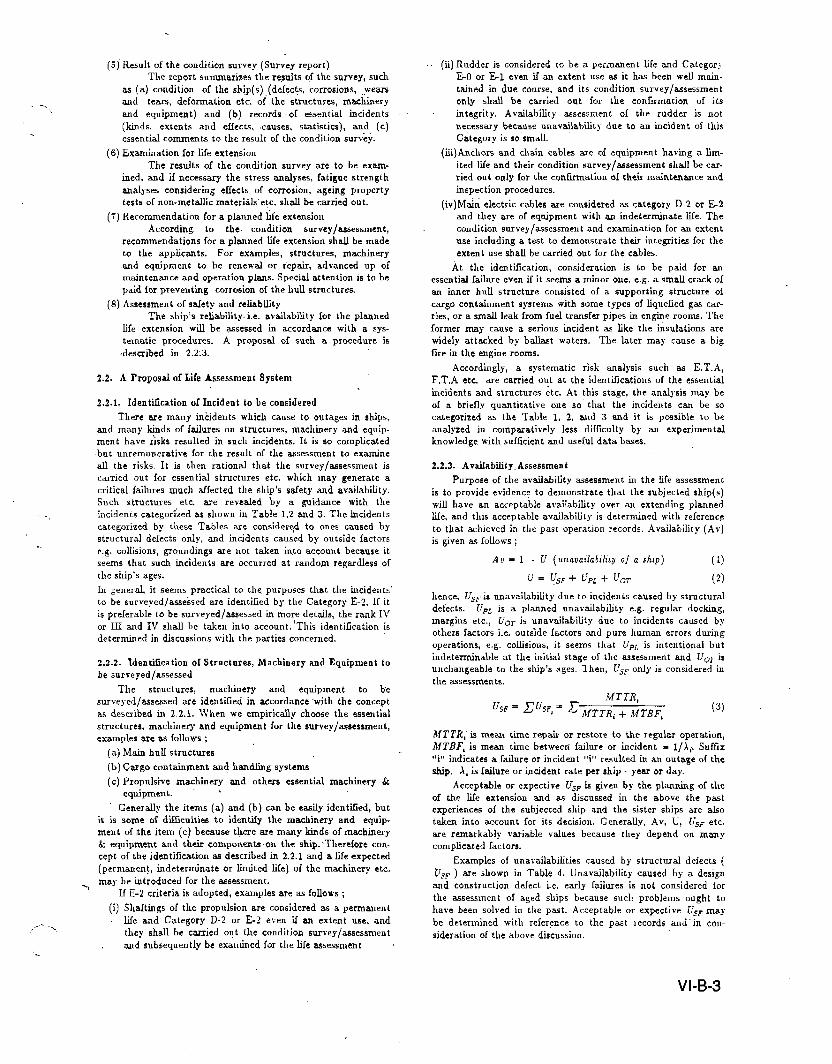
so [W at the execution of rating. Summaries of the rating are
skown in l?ig.2 through Fig.4. Care is to be paid for that the
irrvestigatiorrs were performed to many of the ships with gocds
conditions because of the objective of this study to find a means
for well protecting corrosion. It seems that these Figs skewsome what good examples compared with our experiences,
Ships’ s Age
( Vesr )
15-
10-15
5-1o
-5
1 .. I
levc I
ill c A
❑ CB
❑ cc
CD
k? CE
[ see. 2.41
0 10 20 30 40 50 60 70 #0 90 100
Percent
Fig.2 Skell Plating
Ships’ s Age( Year ) 1*VP I
15- M c A
E ,0
10-15 ❑ cc
CD
5-1o W GE
I 1 ( see, 2.4 )
o 10 20 30 40 50 60 70 Bo 90 100
Percent
Fig.3 Upper Deck
Shim’ s k( Year )
15-.
10-15
5-1o
-5
level
111 c A
❑ =~—
m cc
CD
El CE
( See, 2.4 )
0 10 20 30 40 50 60 10 BO 90 100
Percent
Fig.4 Ballast Tank
“The results of the investigations indicate that ;
(a) Shell plating, especially below the water line are very well
maintained normally, and they are corrosion level in “cB” onaverage, in “cC’! at the worst even after 15 years operation.
There are nothing of the condition “cD” and “cE” in the
investigated hull structures, but such conditions have some-
times found on shell plating especially near or above the
water line dqe to insufficient maintenances.
(b) Upper decks are in more rusty condition than shell plating,
because normally upper decks have not been re-painted for a
long period. Average corrosion level is “cC” for the ships of
age lnOre than 15 ~ems-Old. pitting corrosion were fOun.d Onupper decks of the some ships. Such cases have been o[tenfound on ships less than 10 years-old especially ore carriers,
VI-B-5

Tab],5 ,ExampleofReportandReconunendatimof Condition Survey on Hull( Stip age: 10 years, Top Side WBT )
Historicalroconl1.
I) initially tar epoxy p~t by nOrmal pr=ticc
2) Anod= were provided in all the tanks at 5 years ago, and appropriately supplemented thereafter.3) NO.3 TS WET(P)steel works for repairing shell plates abt. 8m2 and their interred members due to a contact incident.
They haw been re-painted by the same as the initial one.
.,,.
Hall condition ; ratirig ~~ present and recommendation / Prediction
Tk Nos & location at coud. survey recommcud Ifter 5 years (after 7 or 8 years) Ifter 10 yems
No.1TSWBT(P,S) CD(re-~Atit)
cc”(repaint)
(not r-paint)cc”CL
NO.2--4 TSWBT(p,S)(expect here in below)
CB cB/cc cC/cD
Ditto, upperpart. (re-paint)
(re:pAtit)cc”
(Tktop below 3m)cC/cD cc” (not re-paint) CE
NO.4 aft. wJ2 of TSWBT(P,S) cD/cE.
(re~p~nt)cc”
(r.-pairit)(not re-paint)
cc““CE
Snrveyers Note ~It seems initia2 paint works wsre good, and anodes were
effective to places flooded in water at ballast cond, Hull cond.w,ere generally good proportionate to the age.
s0.4 aft. walls were tijacent to FOT, andtheir paints
and ancdes were somewhat ineffective, and the corroded
conditions wtrc as skown in attacked plan.XO. I TSWBT (p,s) kave been used x abnost elnPtY Or
sometimes haU ballasting, and anodes w-ereinelTective.
XB : * skews to ka~e some traces of loca2corrosion.
Designed & Constructed TermsOf,Hull Strctctnre
* Rules, Materials, Service Area* Tern~s & Results of Fatigue
Analyshg (if carried out)* Spec. of Protective Corrosion
y-
Recommendation(I) Anodes to be “refitted in duc course and repaints to be
after touch up works.(z) NO,I TSiYBT andaft.wallofNo.4TSwBT t.be
carefullymonitoredand,after~m 8warstobere-paink~.(3)No.4TSW’BT aft.Wallshavesuiiicie,,tmarg,ntothe$trengthand50111eof heavy corrosious are then acceptable,bowe.er, careful monitoring to be duly csrried out.
---
Service Records of Ships
* Duration, voyage route,loading condition etc.
* Records of maintenanceand inspection, failures.etc. ‘1
Plans of Operationin Fntnre
* Operation Plan
Duration, Service .Irea,Loa#ing cond., etc.
+, maintenance / inspection
plan
+Condition Surveyon Hnll.Ditto, Report
* Actual cond. of..Hnl.l; -describe b~
the categories”
defiied in 2.4
x When category
cE, details ofcorrosion etc.
F’”i; (IPhn ofPtOiectiTe PredictionofHullCorrmion Conditionin* Specification Fntnre
at this time ● This is shown* Plan in future
H:by Categories
in 2.4
Refurbishment * This is indicated(if m-ried) historically to
* Repairing plans individual
members
Figs Pr~edures .1 Hull Strength
~ .1studyonMull Reliability”StreisgtIr Assesment
* Ultimate strength:, “. * Prediction of
This is ex-ed Essential Failureswith the min. ~d
requirement by: “_ O~tage Incident’
rules (Ri.k .4ssessment )
* Fatigue strength * Prediction of
Cumulative dw: L-nav&lability due
age factors: see 4.2”” to h.ilures of Hulf
1. I ~
Assessment
VI’B”6
crude oil carriers etc. 4.1. Hull Strength Assessmeui for Ageirtg Sltips
.,.\
. .
(c) The condition of cargo spaces whose results of the rating ate
not shown herein, depends strongly on the types 01 cargoesand the maintenance. For” instance, cargo holds of car car-riers show frequently superior condition and in contrwt,cargo holds of coal carriers without appropriate coating show
often poorer condition than ballast tanks.
(d) Ball=t tanks are the most corrosive environments. Averagecorrosion level is in between “cC” and “cD” for the ships of
age more than 10 years-old. The conditions of the older ships
more than 15 years vary considerably where about one
fourth of balfast tanks deteriorate under the level “cE”,
while comparable number of baflsst tanks maintain their CON-””
dition in exce~ent state “cB”.
(e) In the investigations there were examined two ships in a very
good condition in spite of their ages nepr zo years, but theirresults are excluded from the summaries in Fig.2, 3 and 4.Their main hull structures were almost rated as IICBII or
above, and they have been operated with an excellent
maintenance plan.. This shows that hulf structures can be
main tained so as good as new for a long time under an excel-
lent maintenance strategy.
Analysis of the results of rating in line of the rating system
introduced may provide valuable and consistent information on
huff conditions to the concerned in the assessments.
3.2. protection of Hnlf .Strnctnres agsinst CorrosionF~lUre~tati~tic~-~)ofoU~Society S11OWthat domirrantcause
offailure for the ships of age older than 10 years are corrosionand the number of corrosion/wutage damages grows as ships
age, characteristic of which can be also seen in the result of rat-
ing mentioned abo~e. There[orel protection 01 hull structure
against corrosion is a cruciaf featrue for the prolonged life ofships. As for the fatigue damage, our statistics show no tendency
of the number of fatigue failures to g-row in aging ships. But, for
the ships 0[ new generation such as the ships with the greater
use of high tensile steel whose fatigue life suspects to be shorter
than. conventional skips with mild stee~ it seems that fatigue
problems may pose another serious obstacles without appropri-
ate maintenance to keep hull condition wwll beyond, say, corrc-
sion level “CC’”.
Research committee organized by this Society in IEMGwithtke experts of coating manufacturers, ship owners and shipbuild:ers. h~vestigated the specifications of coating in building stageand the maintenance procedures to protect bull structures and
equipments from corrosion and report was pubfished as a gui-
dance note in 1986,5)
This Society can advise the applicants in makiug the specifi-
cation of protecting corrosion and also at the planning oi thernainteutice procedure, b~ed on the experience gained from the
analysis of d~age statistics , data on tltickness measurements,
and comprehensive investigation on, aging, skips carried out by
ourselves.
An example -of a recommendation to the maintenance prm
cedures including predictions ,of huf.1conditions is shown in Table
5,.
Trend of corrosion varies considerably depending upon the
types of coating, initial painting procedure especially its work-
manship (most of degraded paint works are caused by bad work-
manship ), environments o{ the structures and so on. Accord-
ingly, periodical monitoring on hnfl condition should be carried
out, where rating criteria introduced in 2.4 may be usefuf infor-mation to grasp the hull condition consistently, resulting in theappropriate maintenance plan based on the analysis of the dat~
4. A sTUDY ON RATIONAL LIFE ASSESSMENT
As discussed irt Chapter 2, there are many problems iu”
developing the rational life assessment system. The authors hare
carri~d out. the basic study, and some of those are summarized in
this chapter.
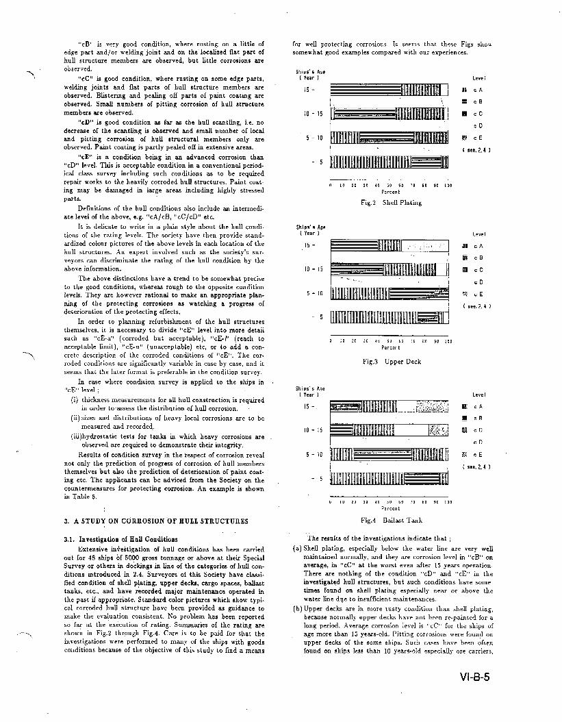
Procedures or the hull strength assessment in the Lifeexten-sion plan is diagranunatical.ly shown in Fig.5 with supplementarynotes given below ;
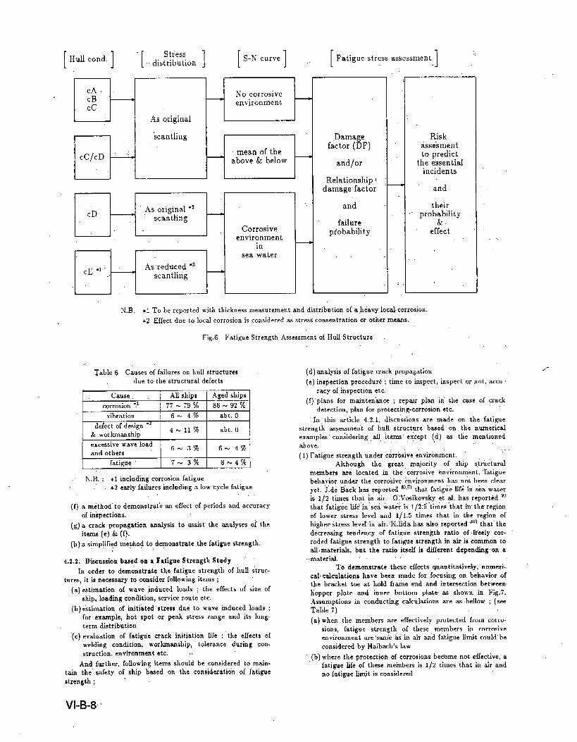
(a) For m example, causes of failures on hull structures due to
structural defects are assumed as show-n in Table 6 from astati$tjcs, 4, It then seems that the failure causes of aged
ships except fatigues have been aknost ehinated providedthat the ship is operated in the same conditions as the past
and the hull structures are well protected from corrosion or
so refurbished as good as newly original scantlings.
(b) Ultimate strength of the huff structures may be evaluated by
success in the condition survey with good refurbishment ts,
because the probability of the failures except those caused by
corrosion and fatigues is expected as the same order to the
past one.
(c) ~ general, fatigue “strength of the conventional hdl ,tr~c.tures has not been examined at the initial design and anyC1=S survey, because experience shows that they have a suffi-
cient margin to the fatigue strength. Cum~ative d-age fac-
tors and failure probabilities are inevitably increased for a
long life over 15 or 20 years. Accordingly, it seems that anexamination is to be carried out in order to demonstrate theinte~ity to the fatigue strength at the life extension study.Procedures 01 the fatigue strength asses.smeu t is shown in
Fig.6 and a discussion of this problem is described in 4.2,
(d) U seems that a new generation of the hull structures has
however a small margin to the fatigue strength. The fatiguestrength of such hull structures are then to be exactly exam-
ined at the Me assessment. Procedures of the fatigue analysis
is shown in Fig.6 and a discussion is described in 4.2.
4.2. Discussion on Fatigue Streugth Assessment
4.2Ll. Gener~
Recently, some members or hull structures with the greateruse of high teusile steels (i.e. a new generation ship) were found
cracked iu early years after the ships entered into service. Itis
supposed that the direct cause of the failures lies in the shortage
of fatigue strength of the local spots of the structnre. In order to
protect such failures, some classification societies developed a
design guidance of the fatigue strength, and this Society also
developed such a guidance. ‘)
Conventional huU structures have also suf[ered fatiguefaifures, but they were sufficiently less than the aforesaid. A
comparison study has been carried out and its result show,s that
a fatigue life of the end connections with lug of ordirrary type on
side longitudinal in the new generation VLCCS is about a half
or less that OC the conventional VLCCS. This comparison not
take into account effects of corrosion, and the fatigue life of the
new generation’s shall be le$s than the above if effects of corr~
sion are taken into account. Therefore, protecting corrosion 01
the hull structures of the new generation’s is more important
problems to the fatigue strength.
As discussed in the above, the fatigue strength ~sessment isone of the most important items to demonstrate the structural
integrity of the hull structures. Analytical techniques and data
to be developed for the assessment are as follows ;
(a) a standard of the fatigue streugtb analysis
(b) S-N curve. including corrosive environmental effects, local
corrosion effects
(c) a method to estimate the stress distribution in the past
and the future. i.e. strength analyses method and ratigue
load estimation method according to the ship’s operation
area”
(d) a method to estimate relationship between cumulative
damage and failure probability y.
(e) a risk assessment method of the fatigue failures. i.e. ~ ~.ti.mation method of the incident effects and probabilities dueto the fatigue failures
VI-B-7
r (Fatiguestressassessment1 :,
DCACBcc
.’
Dcc/cD “:
As original
‘scantling
No corrosiveenvironment
—
Corrosiveenvironment
insea water
.Damagefactor (DF
and/or
Relationshipdamage factor
and
failureprobability
Riskasseimentto predict
the essentialincidents
and
theirprob~bility
effect
UILN.B. *1TO be reported with thickness measurement and distribution Of ah~av,y local corrosion.
%2 Effect due to local corrosion is considered as strew consen trativn or otker means.
,.’
Fig,6 Fatigue Strength Assessment of Hull Structure
~able 6 Causes of failures on hull structures
due to the structural defects
excessive wave load 6%3% 6* 4%and others
fatigue 7-370 8N4%
. N.B.; *1including corrosion fatigue. *2 early failures including a low “cycle fatigue
(f)amethod” to demonstrate an effect of periods and accuracy
of in’zpections.
(g)a crack propagationanalysistoassisttheanalysesortheitemi(e)& (f).
(k)a Sjrrrpl$:dmeykodtodemonstratethefatiguestrength.
4,2.2. Discussion based on ● Fatigue Strength Stnd~ ““
fn order to demonstrate the fatigue strength of hull “struc-
tures, it is necessary to consider foUowing items ;
(a) estimation of wave induced loads ; the effects of size of
ship, loading con{ltion, service route etc.
(b) estimation of initiated stress due to wave induced loads ;
for example, hot spot or peak stress range and its long-
term distribution
“(c) evaluation of fatiW”e crack initiation Me ; ‘the effects of
welding condition, workmanship, tolerance during con-
struction, environment t etc. ,.
And, further, following items should be considered to main-
tain the safety of ship based on the co]lsideration of fatigue
1’,,
(d) analysis of fatigue crack propagation
(e) inspection procedure ; time to inspect, inspector not, accu-racy of inspection etc.
,.(f) “plans for inainten’mce i repair plan ii the case of crad”
detection, plan for protecting-corrosion etc..,
In. this article 4.2. L d~scu”ssions are made on the fatiguestrength ass.essmelit of hull structure based On t}e numerical
examples” considering ~ ‘iterni except (d) as the mentioned.,, ,.<above.
.,
(1) Fatigue strength under corrosive ●nvironment. ~ ‘Although the great majority of ship structural
members are located in the “corrosive environment, ‘fatigue
bel~a~~or under the “corrosive environment lIU not been clearyet. J.de Back has reported c)r~l that f~tigtiilife in sea water
is 1/2 times that k &r. O“Wosikovsky et al. has reported ‘)’that fati~e life”in ‘sea water is 1/2:S “times “that in’ the region
of lower stress level and 1/1.5 times that iu the region 01
higher stress lewel iir kir. ‘K,fida has afso reported ‘o) that’ tke
decre=ing ttndency of fa~@e strength ratio of freely” cor-
roded fatigue strength to fatigue strength in air is common to
alf, materials, but‘theratioitselfk differentdependingon a.,material. .,, .,.
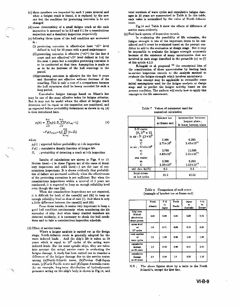
To demonstratetheseefkctsquantitatively, nurneri-,
cal circulations have been made for focusing on behavior ofthe bracket toe at hold frame end and intersection between
hopper plate and inner bottom plate as shown in Fig.7.Assumptions in conducting calculations are as bellow ; (see
Table 7)
(a) when the members are effectively protected from corro-
sion, fatigue strength of these members in corrosive
environment t are ‘s~e k in air and fatigue limit could’ be’
considered by f-faibach’s law
‘. (b) wheie the protection of corrosion becbme not effective, a
fati-@e life of these members’ is 1/2 times that in tir and
no fatigue limit is consideredstrength ;
VI-B-8
(c)these membersareinspectedbyeach2yearshierwalandwhen a fatigue crack is found, it is replaced by the newone but the condition for protecting corrosion is be notchanged
(d)rncan detcctabfityofa smallfat;gnecrackattheeachinspectionk ~smmed tobe0.9and0.1foraconscientiousinspectionanda desultoryinspectionrespectively
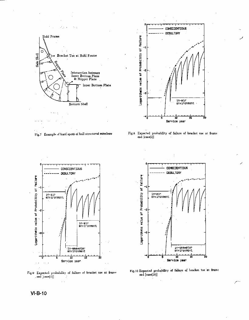
(e)followingthreetypes of the hull condition are accounted~;
(i)protectingcorrosion is effective(at least “cC” leveldsfined in 2.4) for 20 years with a gwd maintenance.
(ii) protecting corrosion is effective (“cC”) for the fist 8years and notetiective(’’cl)”leveldefinedin2.4)forthenext4 yearsbutacompleteprotectingcorrosionistobeconductedatthattimaAmrnptionh made soas to be no demeaseof thehullscantingsin theperiod.
(iii) protecting corrosion is effective for the timt 8 yearsand thereafter not effective without decreswe of thescantling. This is only a case of a comparisons because
the hull structures shall be heavy corroded for such along period.
Cumulative fatigue damage based on Miner’s lawmay be one of the most effective index for fatigue criterion.
But it may not be useful where the effect of fatigie crackdetection and its repair at the inspection are considered, andan expected failure probabtit y formulated se shown in eq. (4)is then introduced here.
,-0 j-1k-l
where
pfli) ; expected failure probabtit y at i-thinspection
~~) ;copulativedensityfunctionoffatiguelife
D, ; probability of detecting a crack at i.th inspection
(4)
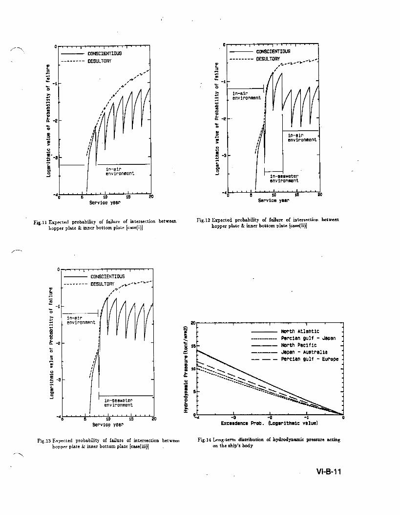
Results of calculations are shown io Figs. 8 to 13.
Broken l.hes(---) in these Figures em of the cases of desul-tory inspections and solid lines(-) are the case of con-scientious inspections. It is shown evidently that probabfi-ties of failure are incre~ed suddenly when the effectiveness
of the protecting corrosion is not sufficient. But when the
conscientious inspections within a interval of 2 years are
conducted, it is expected to keep an enough r~abfity level
even though the case (iii).When the conscientious hmpections sme not expected,
it is disXcult for both of the cases(ii) and (iii) to keep ass
enough reliability level ss thatofcwe(i).Andthereis only
a little difference between the cases(ii) and (iii).
From these results, it seems very important to keep agood hull condition continuously when considering the life
extension of ship. And when many cracked members are
detected .uddcrdy, it is necessary to check the hull condi-tions and to take a conscientious inspection schedule.
(2) Effect of service route.
Where a fatigue analysis is carried out in the design
stage, North-Atlantic rou”te is generally adopted for the
wave induced loads . And the ship’s life. is taken as 20
years which is equal to 10s cycles of the acting wave
induced loads. But for some spe~]c ships, they sme takers
into account the actual service route in evaluating the
fatigue damage. A study has been carried out to .x-e a
difference of the jatigue damage due to the service routes
mnong (a) North-Atlsntic route, (b) Persisn Gulf-Japan
route, (c) North-Patic route and (d) Japan-Australia route.
As an example, long-term distribution of hydrodynamic
pressures acting on the ship’s body is shown in Flg.14, and
total numbers of wave cycles and cumulative fatigue dam-
ages in 20 years are snrcmuuized in Table 8. IO this table,
each value is normalized by the value of North-Atkmticrcmte.
Fig.14 and Table 8 show the effects of dflerence of
service routs evidently.
(3) Feed back system of inspection records.In evaluating the possibtity of life extension, the
fatigue strength is one of the important items to be con-
sidered and it must be evaluated based on the present con-
dition to add to the evaluation at design stage. But it maybe impossible to evaluate the fatigue strength accuratelybecause of the existence of many uncertainties that areinvolved in each stage described in the preamble (a) to (f)of this article 4.2.2.
H.Itagaki et rd. proposed 10) the ,onceptud idea or
the consideration or these U.ucertuinti.s by feediug backin.service ins~ction records to the ansdysis method toevahtate the fatigue strength which involves uncertain y.
‘1’Ms concept may be applicable to reconsider someNltial assumptions used for the fatigue analysis at designstage and to predict the fatigoe activity based on thepresent condition. The authors will study how to apply this
concept to the life wessment.
Table 7 Values of prmuneter used fornumerical calculation
bracket toe intersection bet weenrS-N curve
[N, S“’ - C]
in air; N <2x10C
m
cinair; N>2x10⁶
m
csea water
at frame end
2.3SfI
2.75x10S
3.780
4.82x 10s
hopper plate..
& inner bottom plate
6.2932.43x1013
11.586
2.21%1019
m 2.390 6.293
c 1.38x10⁸ 1.22X10¹³
std. dev. in(N) 0.5 0.5
local stress22.2 42.02
at hot point
Table 8 Comparison of each route
(example of bracket toe at frame end)
North P-G Norlh Jspul P-G
Atlantic ‘0 Pxilicb to
kpul Auslrsh Europe
long termWeibull
dktribution0.91 0.ss 0.92 O.ia 0.92
shap pnmm.
itscMIcvel●c 1.0 0.11 0.99 0,76 0.82
lo~Cych
told numb0{ 1.0 1,20 0.06 1.20 1.06
wave Cycses
cumulativedamege 1.0 0.s4 0.s6 0.41 0,55
●t 20years
cumulativedunq, 2.0 0.6s 1.9 0.82 1.10t~40 yeare
N.B ; The abovefigures show by a ratio to the North
Atlantic’s, except the tit line.
VI-B-9
===_’-l.’.: “.;
Hold Frame.
,-”
,* ,“
~- Bracket To-i at Hold Frame
Intersection between
Inner Bottom Plate
Bottom Shell
##
‘$
,*
/’,, R’
t’
/
-,.
“ “/1’r’:i’—,L
5 10 16 20Serviceyear
F;g~7 Ex*~le of htid” spots of hull structural members Fig.8 Expectedprobabilityoffailureofbrackettw atfrancend[case(i)]
-1 I I I (
CONSCIENTIOUS
-------- DESULTORY
0) 1 I I 1
I CONSCIENTIOUS
DESULTORY
-L--L--L-,,” -0
in-airenvironme
6 10 15Service year
“1i.
.“
1’
:.:
f’
~_,Eaw,ter
environment
in-airenvironment
—later
-4 -4 Iii. .lli!. l.l. il.,.o 5 io 15
Service yeerI
Expected. probability of failure of bracket toe at frameFig.10 Expected probabfit y oi fsii!mre of bracket toe “at frame
end [case( ii)] .end [c@ii)]
Fig..9
I CONSCIENTIOUS
OESULTORYI
-4; ‘ 1I I I I
5 io i8 20
Serviceyear
Fig.11 Expected probability of failure of intersection betweenhopper plate & inner bottom plate [c=e(i)]
,/- --
0 I I I
CONSCIENTIOUS
I--------DESULTORY Z~--L--L-,./’
,0
z
-1in-air
m environmentHn
;
k -2
I
in-seawatarenvironment
-4A 1 1 I I L5 io 15
Service yearD
Fig.13 Expected prObabfity of fdure Of intersection between
hopper plate & tiner bOttom plate [case(iii)]
0 I 1 I
CONSCIENTIOUS
I
-------- OESULTORY _-k - -1. ... Z-L--b 1
,1-40 I 1
5 io 13 20Service yeer
Fig.12 Expected probability y of failure of intersection betweenhopper plate & inner bottom plate [me(ii)]
E%ceBdanmProlJ.Logarithmicvalue)
Fig.14Lon@nn distributionOfhydrodynamicpmwue actingontheship’sbody
VI-B-11
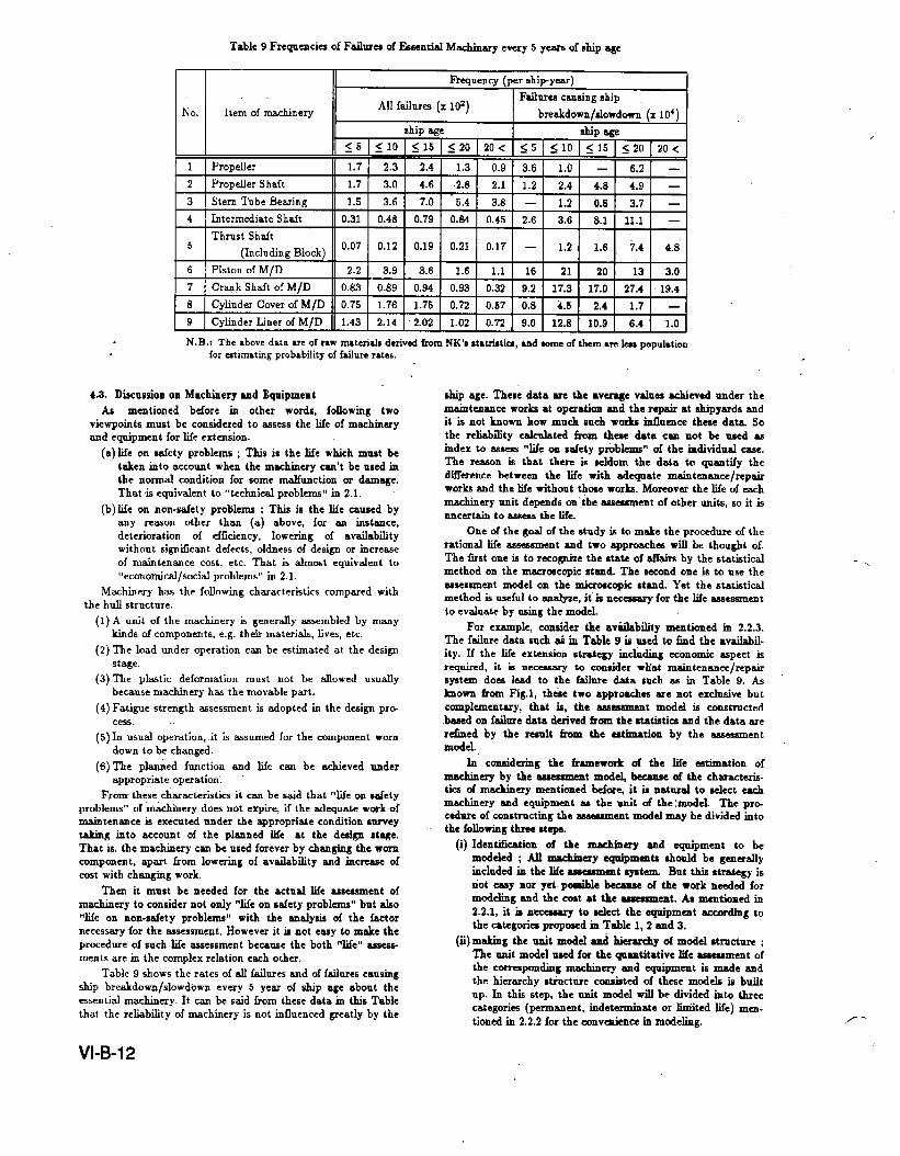
Table 9 Frequencies of Failures of l%entisd Machinary every 5 years of ship age
Frequency (per ahi~year)
Failure+ causing ship
No. Item of machineryAll failnrm (x 102)
breakdown/slowdown.(x 104)ship age ship &ge
55 ~ 10 ~ 15 ~ 20 7.0< 55 ~ 10 <15 ~ 20 20<
1 Propeller 1.7 2.3 2.4 1.3 0.9 3.6 1.0 — 6.2 —
2 Propeller Shaft 1.7 3.0 4.6 .2.8 2.1 1.2 2.4 4.8 4.9 —
I 3 I Stern Tube Bearirm II 1.51 3.61 7.01 ”5.41 3.81 –1 1.21 0.81 3.7] –14 I Intermediate Shaft I 0.31 I 0.48 I 0.79 I 0.64 I 0.45 I 2.6 ] 3.6 I 8.1 I 11.1 I —
I Thrust Shsft II I I I I I I I I5
(Including Block) 0’07 0“12 0“19 0“21 0“17 – 1“2 1“6 7’4 4-8
6 I Piston of M/D 2.2 I 3.9 I 3.6 ] 1.61 1.11161 211 201 131 3.0
7 I Cr~k ShaJt of M/[D I 0.83 I 0.89 I 0,94 I 0.93 I 0.32 I 9.2 I 17.3 ] 17.0 I 27.4 I 19,4
4/D II0.75 I 1.76 I 1.75 I 0.72 I 0.57 I 0.8 I 4.5 I 2.4 I 1.7 ] —
I 9 I Cylinder Liner of M/D II 1.43 I 2.14 I 2.02 I 1.o2 I 0.72 I 9.o I 12,8 ! 10.9 I 6A I I.O I
N. B.: The above data We of raw materials derivd fmm NK’m stmtristim, &nd tome Ofthemmm~ pOPU]~tiOnfor intimating probability of f~ilurs rmte.s.
4.3. Discussion on Machinery and EqnipmeutAs mentioned bdore in other words, following two
viewpoints must be considered to ~sess the life of machimeryrmd equipment for I.& extenion.
(a) life on safety problems ; This is the life which must betaken into account when the m~hinery csn’t be used inthe normal condition for some malfunction or damage.
That is equivalent to “technical problems” in 2.1.
(b) life on non-safety problems ; This is the life caused byany reason other than (a) above, for an instance,deterioration of dficiency, lowering of availabilitywithout signticant ddects, oldness of design or increaseof -tenace cost, etc. That is almost equivalent to,,econo~c~isocid problems” in 2.1.
Machineryhssthefollowingcharacteristicscomparedwiththehdlstructure.(1)A unitofthemachin.ryisgenerallyassembledbymy
kindsofcomponents.e.g.theirmaterials,lives,etc.(2)Theloadunderoperationcanbeestimatedatthedesign
Wage.(3)The plasticdeformationmustnotbe allowedusually
becausemachineryhasthemovablepart.(4)Fatiguestrengthassessmentisadoptedinthedesignpr~
cess(5)Inusualoperation,.it.is-snmedforthecomponentworn
downtobechanged.(6)The plannedftmctionandlifeC= be acbiev.dtutder
appropriateOperatic.’.Fromthesec~macteristicsitcanbeSaidthat“lifeonsdcty
problems”of~dbincrydoesnotexpire,iftheticqnateworkof-tensmce isexecutedundertheappropriateconditionsurveytakingintoaccountoftheplannedlifeatthedesign stage.That is, the machinery can be used forever by changing the worncomponent, apart from lowering of availabilityy and increase ofcost with changing work.
Then it must be needed for the actual life =sessment ofmachinery to consider not only “life on ~dety problems” but also“life on non-safety problems” with the analysis of the factornecesswy for th-t =scssmcnt. However it is not easy to make theprmedure of such life assessment because the both “life” assess-ments are in the complex relation each other.
Table 9 shows the rates of all failures and of failures causing
ship brcakdon/slowdbwn every 5 year of ship age about theessential machinery. It can be said from these data in this Tablethat the reliability of machinery is not influenced greatly by the
VI-B-12
drip age. These data = the avcr&e vdum achievedtinderthemaintenanceworksat operation and the repair at shipyards andit is not how-n how much snch winks irdlnence these dat~ Sothe reliability calculated from three data cm not be used asindex to assem “life on rdety prbblems” of the individual case.The reason is that there is seldom the data to qnmtify thedifferencebetween the life with adequate mdntensmcc/repairworks and “the life without those works. Moreover the life of eachmsuhinery unit depsnds on”theassessmentof othertits, so it isuncertain to asmss the I&.
One of the goal of the study is to make the procedure of therational life assessment and two approaches will be thought of.The first one is to reco@ze the state of tiairs by the statisticalmethod on the macrmcopic stand. The second one is to use theassessment model on the microscopic stand. Yet the statisticalmethod is useful to anal~e, it”is necessary for the Iifc assessment
to evaluate by using the model.
For example, consider the aviilstbility mentioned in 2.2.3.The failure data suds ti in Table 9 is used to hd the availabil-ity. If the life ●xtension strategy including economic aspect isreqnircd, it is nec~ to consider wliat mdnten~cc/repairsystem does lead to the failure data euch ~ in Table 9. As “’bown horn Fig. 1, thtie two approaches are not exclusive butcomplementary, that is, the aaeesament model ii constructed
b=ed on fake data derivedhorn the statistics and the data arere~ed by the rasrtlt horn the ~tirnation by the aswssmentmodel.
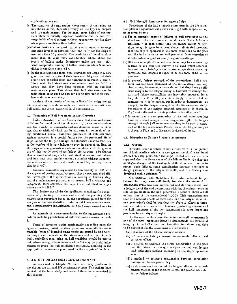
Ir” comidering the tiunework of the life estimation ofmachinery by the ~sment mcdd because of the characteris-tics of machinery mentioned Idorq it is natural to select eachmachinery and equipment at the unit of the: mcwleL The pr~cednrc of cosmtrncting the ~~ent mdd may be divided intothe’ following three steps.
(i) Ident&ation of the _ery and eqrsipment to bemmieled ; Ml ~ery equipments should be generallyincluded in the life ass~att system But this strategy isnot essy nor yet. poedile ~ of the work needed formodeling and the cmt St the’ uussment. As mentioned in2.2J, it is smcessary to sckt the cquipmemt according tothe categosim proposed m Table 1, 2 and 3.
(ii) making the unit m&I and I&rchy of model stmcture ;The unit mcdel used for the quantitative life assessment ofthe comespc.nding machinery and equipment is made andthe hierarchy stinctsrxe consisted of these models is built
UP. In th~ step, the ssxdtmwlel will be divided into threecategories (permanent, indeterminate or hited life) men-tioned iu 2.2.2 for the convmience in m&ling. /--”

F===i
,------------------------ -------------- . . . . . . .
I
--------------------------------------------- ;Hiersrcky of Model Structure
1Life
Ass=sment *
Model
uFig,15 Concept of Model Structure for life Assessment
{Maintenance/Repsir Plsn,
Unavailability}
{Maintenanc~/Repair Plan,
Unavailability}
(iii)constrictionofthelifeassessmentmodel;The lifessBess- asscssment.Whereiomeofdeficienciesarefound,theyrwe“rrwnt model for gathering the data used in the fife msess-
ment by the unit model hier~chy of (ii) is constructed.
Fig.15 shows the hierarchy of the unit model structure. It
may be as almost same = E.’T.A.andF.T.A.,andisinvestigatedindetailnow.
4.4.Miscellaneous
Intheship,therek mmy structures,machineryandequip-mentotherthanthoseaforesaidofwhichfailuresmay essentiallyaffecttotheavailability.Commentstothemiscellaneousareasrollows;(1)Cargocontainmentsystem for liquefied gas carriers.
The c=go tanks of refrigerated liquefied g= czu-riers
are generally not corroded and some of them have been
carried out a fatigue strength analysis at the idial design.
The assessment to such a c=e is carried out with less d~-
culty than that of the hull structures, because reference
cam be made to the design data and the corrosion effects
are not taken into account. Procedures of the fatigue
strength assessment are simik to that of the hull struc-
tures in principle. Relationship between cumulative dam-
age and failure probability is to be studied for the unavai-
lability assessment.
Insulation systems are considered as an indeter-
minate life and data of ageing effects of the materials are
to be examined taking into account the past operation
data and, if necessary, a test to demonstrate the ageing
effects shall be carried out.
Others, e.g. secondary bmriers, tank supporting
material etc. are also ex-ed on their properties of the
ageing effects.
(2) Cmgo hemdling system
Cargo handling system are one of the essential equip-ment of which failures may affect to the unavailability.
The systems and their components then are objective of
the wsessment. The components have a different naturein each, e.g. the cargo pumps are of a limited life, the pip%5 me Ofa Permanent W some Ofthe components havebeen designed with a fatigue analysis etc. The ~sessment
are then to be carried out in an applicable manner respec-
tively.
(3) Safety equipment
Safety equipment are related to not only the skip’s
safety but also the availabfity. e.g. a failure of the fire
exting&hment system may result in a big fire accident
from a minor one. Safety equipment are to be seriously
examined by the governing bodies and ship’s crews in view
of the ship’s safety rather than availability y. They are how-ever not always perfect, and an examination of the safety
equipment is then necessary in the condition survey/--%
of course to be refitted in order.
5. CONCLUDING REMARKS
Conclutig rerrmks of the study are as follows ;
(a) A simplified system for the life assessment h= been pro-posed. Main objective of the proposal is m aged ship in a
good condition which is expected to continuously operate
with a high reliabfity S* to that of the past. However
the proposal is also applicable to any kinds of ships.
(b)Iri order to efficiently carry out the assessment as far as
possible, it is necessary to provide back up systems sup-
ported by data bases. Necessary Eortsof the systems havebeen ed ed and cbifled, and snbseqnently some of
such systems = going to develop. If the systems me com-
pleted, works of the assessmmds will be remarkably
decreased. From our experience, it can be said that a fullzwsessment required abt five or above person- year’s works
at present will be performed by abt five or above person-a
half year.
(c) &tensive investigations were carried out for conchtions ofthe hull structures. According to the result, we stress thatmeans for protecting corrosion which me used to a general
practice to mmy ships is insufficient to maintain a god
conditim oi the hull strnctnres far a long life. It is then
preferable to be developed a high standard of protecting
corrosion, and a guidance involved has been proposed to
this end.
(d) Discussions have been made to the hull strength assess-ment including the fatigue strength. Comments to the
fatigue strength of the hull stmctnres in the life assessment
have been described as a result of the study. For example,
it has been demonstrated that notwithstanding an increaseof the fatigue cumulative dsunage for a long life, risks of
the outages due to the failures can be controUed withii an
acceptable level by a pertinent inspection strategy/methd
and a god maintenance plan.
(e) Deficiencies of the essential mrwhiuery and equipment
much affect to the ship’s unavailability as well as the huUstructure’s. The assessment of those csm not be disre-
garded, and a discussion hw been made to develop theassessment system involved.
(f) The most complicated problem of the life assessment is to
predict the failure rates taking into account ageing effects
of the essential structures, machinery, equipments and
their components, besides many problems me to be exam-
ined for the reflnr.ment of the =sessment system. The
extensive studies involved shall be continued in order to
make a snccess of the rational assessment system.
VI-B-13

ACKNOWLEDGEMENT
The authors wish to acknowledge to persons who rendered
their s.mistace and gave valuable comments to this study. Par-ticular thanks me also to the shlppingcompmy which gssve usa
chance to participate m actual Me extension study.
1)
2)
3)
4)
5)
6)
7)
8)
9)
REFERENCE
NK, On Condition mn-vey/assessrnent of hell structures,
Sept. 1989 (in Japanese)
B. de Frondevde, Reliability and Safety of LNG shipp~g :
Lesson from Experience, SNAME Nov. 1977.
J.J. Cue. et al., Operating experience with LNG carriersaPPl@qtheskirtSupportedsphericalcargotankdesign,6thLNG conference,19S0NK, Statistics of failures on hull structures from 1980 to1s89 : annually published by NK’ transactions in 1981 to1990. (in Japanese)
NK, Guide to protection against corrosion of ship’s hull
and eqoipment, 1986 (in Japanese)
NK, A goidance of fatigue strength to longitudinal frsimes,
Oct. lwo (inJapanese)
J.deBack,“Strsngth of Tubular Joints”, Proc. of Intern*
tionsd Conference Steel in Mrmine Structures, Paris, 5-8
oct. 1981
J, de B&k, “The Design Aspects and Fatigue Beha~our of
Tublan Joints;, Proc. of International Conference Steel in
M@re Structures, Ansterdaq 15-18 June 1987
Vosikovsky et aL, “Effects of Cathodic Protection and
Thickness on Corrosion Fatigue Life of Welded Plate T-
Joints”, Proc. of International Conference Steel in Marine
Structures, Amstmdmn, 15-18 June 1987
10) K. Iida, “State of the Art in Japan”, Proc. of InternationalConference Steel in Marhe Structures, Amsterdam, 15-18
June 1987
11) H. Ita6aki et al,, “Bayesian Reliability Analysis for Evaluwtion In-Service Inspection”, The Society of Marine Science
of Japan, Current Japanese Material research VOI,5 Recent
studies on structural Safety and Reliability
,-
VI-B-14
DISCUSSION
Bahadir Inozu
Firstofall,Icertairdyagreewithyourconclusionthatyoudidn’tmentioninyourpresentationthatthemachinerymaintenancehas tok consideredin additionto thestruc-tumlreliabilityinorderto ensureship availability.We’veseenalotofpapersaboutstructuralreliability.It’sveryexcitingtheSMP projectthatProfessorBob Beahasinitiatedfinallystartedbutwe shouldalsoconsidertheshipmachineryavailabili~.
Inyourpaperyoutalkabouttwoapproachesforthemachinerymaintenance,YoufusttalkaboutthemicroscopicstandwhichisbasedonthestdslicalapproachthatyoujustmentionedFirstofall,we knowthatthestatisticalmethodsrequirelifetimedata.However,theexistingfielddatak heavilycensoredleadingtogreat‘uncertainties,Whatdoyoumeanwith“microscopic”stand?Areyouplanningtointegratefaultdiagnosistech-niqueswithstatisticaltechniquesordoyouhaveanyotherapproaches?
ThesecondcommentthatIhaveisaboutyourTable9thatI thinkk misleading.Inthistableyoucomparethemachineryfailureswiththeship’sage.Basedonthistable,youstatethatthereliabilityofmachineryisnotinfluencedgreatlybytheshipage.Theresultsdonotagreewiththebath-tubcurvethatwouldindicatethatthenumberoffailuresreallyincreasewithageaflertheinfantT-.
/ mortalityperiocLThenumberoffailuresshouldbecom-paredwiththeageofthemachineryitself,nottheageoftheship.
A. Kumano
We thankyouforyourdeepinterestinourpaperandforyourquestionswiththepoin~
The answerto the fust questionis as follows. As men-tionedinourpaper,wethinkit isnecessaryfortherationallife assessmentto considertheprocedureon both macro-scopic and microsmpic standpoints. One of the mainreasonsforusingtwostandpointsisjust theuncertaintiesof the statisticaldataas indicatedin yourqueaion. So itwill notbe ableto makeassessmentprocedureftomonlythe stadsticalmodel. To cope with thisproblem,we arenow studying the assessmentmodel shown in Fig.15,which simulatesthe assessmentprocedure. This modelhasthehieramhicalstructuremadefrommanyunitmodelscorrespondingto the adequategrain for the assessment.Theunitmodelatthelowestlevelofthishierarchywillhavethedataoftheresiduallife,themaintenanceandtheoperationenvironmentasitsinternalcomponentsusedatthelifeassessmentTheassessmentprocedureis,inasense,thesemanticsofthishiemrchymodel.Ofcourse,itisimpossibleforthisclosed-worldmodeltodealwiththerealopenworld.Sowethinkthattbestatisticaldata.willbeusefulastheinterfacebetweenthismodelandtherealwodd,Inotherwords,weshoulddeterminethestructureandthecomponentsintheassessmentmodelastheymustbecompatiblewiththestatisticalmodelbe-tweentheassessmentmodelandtherealworld.Atthistime,wecan’tsaythedetailofthemodelstructure,forexample,whetheritmaybeasalmostthesameasthetreestructureusedinvariousfaultdiagnosiswchniques.
Theanswertothe$eccmdquestionisasfollows.Weagreewithyouropinion,Asmentionedinourpaper,itismturaltoconsiderthatthedatainTable9shouldnotbeusedintheassessmentprocesswithoLIttheadequate.modiilcation,becausetheyaretheaveragevaluesachievedunderthemaintenanceworksatoperationandtherepairattheshipyard.Byshowingthesedataindicatingthepresentcondition,we wantonlytosuggestthatthepracticalmaintenancemethodsisuseful.We thinkitwillcon-tributetomaketherationallifeassessmentsystemtogeneralizethesepracticalmethodsintheassessmentprocess.
VI-B-15