ac 2007-251: development of nde laboratory for aet ... · undergraduate courses in physics,...
TRANSCRIPT

AC 2007-251: DEVELOPMENT OF NDE LABORATORY FOR AET STUDENTSAND CERTIFICATION PROGRAM
Vladimir Genis, Drexel UniversityDr. Vladimir Genis, Associate Professor and Program Director of Applied EngineeringTechnology in the Goodwin College, Drexel University, taught and developed graduate andundergraduate courses in physics, electronics, biomedical engineering, and acoustics. Hisresearch interests include ultrasound wave propagation and scattering, ultrasound imaging,electronic instrumentation, piezoelectric transducers, and engineering education. He serves as amember of the Drexel’s Faculty Senate.
David Spang, Burlington County CollegeDr. David I. Spang, the Dean of Science, Mathematics, and Technology at Burlington CountyCollege, holds a PhD degree in Material Science & Engineering and a MBA degree with aconcentration in Innovation & Technology Management, both from Rutgers University. He hasmore than 20 years of experience in the Solid State Materials and Chemical Process Industries invarious Research, Process and Business Development positions.
Alexander Genis, G I I, Inc.Alexander Genis, Business Development Consultant, holds a BSEE degree in Electrical andComputer Engineering from Drexel University and MBA degree from Temple University. He hasmore than 12 years of software development and management experience. He evaluated,implemented, and documented the new technology solutions in support of business goals toachieve increase in productivity and return on investment.
Tony Midora, PMT, Inc.Tony Midora, has over 20 years of experience in NDE field and he holds ASNT certificate. Heprovided sales and customer support of testing applications with leading ultrasonic testingcompanies, including Sonic Instruments, Staveley NDT Technologies, Panametrics NDT, andKrautkramer Ultrasonic Systems. He is currently working with Precision MeasurementTechnology representing GE Inspection Technologies Ultrasonic and Eddy Current NDE group.
© American Society for Engineering Education, 2007

Development of NDE Laboratory for AET Students and Certification
Program
ABSTRACT
Drexel University’s Goodwin College of Professional Studies is in the process of developing the
instructional materials for its nondestructive evaluation (NDE) course by placing emphasis on
techniques and applications in the areas of manufacturing, power generation, oil and gas
production, structural and pipeline welding, and commercial/military aviation maintenance,
among others. Students enrolled in the Bachelor of Science in Applied Engineering Technology
(AET) program will be the main target audience. They will have access to the developed material
in two modes: the traditional face-to-face classroom mode for those on Drexel’s campus, and a
real-time, Internet-based videoconferencing mode for those attending classes at remote locations,
specifically students at community colleges partnering with Drexel. The developed instructional
materials will be part of a wider STEM (Science, Technology, Engineering, and Mathematics)
initiative, including the development of novel teaching and learning strategies, the creation of
new learning materials, and the implementation of effective assessment and evaluation
techniques. Additionally, these novel teaching and learning strategies will be incorporated into
the curricula of Drexel University’s two-year college partners, such as Burlington County
College and Delaware County Community College. The outcome of the proposed project will be
a hands-on laboratory course in which NDE techniques of parts and materials will be presented
and applied through real-life problems. NDE curriculum will be designed to fulfill Levels I and
II NDE in theory and training requirements, according to American Society for Nondestructive
Testing (ASNT ) Recommended Practice No. SNT-TC-1A (2001). Once fully developed, the
NDE laboratory will serve as a training center for engineering technology students, as well as for
the workforce of local companies, such as Boeing, Lockheed Martin, and PECO Energy, with
whom Drexel has a rich history of partnership in terms of internships and research
collaborations. Such educational laboratories are nearly non-existent in our geographic region,
and consequently will be welcomed by the industrial community in need of engineering
technologists who can competently utilize NDE instrumentation and to provide support to the
designers and engineers in testing applications.

INTRODUCTION
Drexel University is the only institution of higher education in the Delaware Valley and Greater
Philadelphia Region that offers a Bachelor of Science (B.S.) degree in Applied Engineering
Technology (AET). One of the goals of Drexel’s Applied Engineering Technology program is:
‚ To become a national model for the delivery of high-quality, affordable, technically-
oriented education by focusing on student-centered learning and the integration of hands-
on laboratory and industry-based experiences.
To achieve this goal and improve the learning, the Drexel’s Goodwin College is in the process of
expanding and upgrading its educational facilities by implementing a series of well-designed
strategies and developing new state-of-the-art laboratories. These facilities will allow all AET
students to be involved in the educational, research, and training process and also will alleviate
the shortage of trained specialists in applied electrical, mechanical, and manufacturing
technology. The key factor in the development process is the creation of educational laboratories
that can significantly contribute to the development of technologically literate students and
workforce. These value human resources could be in great demand, not only in the tri-state area
but also nationwide1.
OBJECTIVES AND SIGNIFICANCE
The objective of the proposed project is to develop a course with a problem-based learning
approach to nondestructive evaluation (NDE) of materials using Internet Protocol (IP) networks
for undergraduate AET students. This is a hands-on, three-credit course (within the frame of
Drexel’s quarter system) consisting of laboratory work each week with just in time lectures. The
outcome of the proposed project will be a two-part course: the first part with an emphasis on the
foundations of NDE, and the second part during which NDE techniques of parts and materials
will be presented and applied through real-life problems. Specifically, the students will learn the
engineering and physical principles of measurements of sound velocity in different materials,
attenuation coefficients, directivity pattern of ultrasonic transducers, and location and dimensions
of heterogeneities in various materials, such as holes, cracks, cavities, and flaws. The work in the
laboratory will enhance the fundamentals taught in the classroom sessions.
The proposed ultrasound NDE educational laboratory will serve as a training center for
undergraduate AET students, as well as for the workforce of companies, such as Boeing,
Lockheed Martin, and PECO Energy, with whom Drexel has a rich history of educational and
research partnership. After careful consideration and discussions with the largest employers in
the Atlantic region, representatives of the ANST, and based on our research, educational, and
engineering experience, we came to the conclusion that the creation of a unique ultrasound NDE
laboratory would significantly benefit our students and working engineering personnel. The
establishment of a state-of-the art laboratory for NDE purposes will allow Drexel and its
community-college partners to develop training options for technicians located in the region’s
key industries. NDE curriculum will be designed to fulfill Levels I & II NDE in theory and
training requirements, according to ASNT Recommended Practice No. SNT-TC-1A (2001)2.

During the past two years, an introductory, laboratory-based course in ultrasound imaging was
developed and offered at the undergraduate level in the School of Biomedical Engineering at
Drexel University 3. The course exposed students to basic applications of ultrasound
measurements related to medicine, primarily through laboratory activities. Lecture time with
students allowed for the introduction of topics included in the laboratory experience, such as
measurements of sound velocity in different materials, attenuation coefficients, and directivity
pattern of ultrasonic transducers. The objective of the proposed project is to implement the
developed material into a format suitable for undergraduate AET students and expand it to an
Internet-based course composed of an introductory laboratory course with a problem-based
learning approach to NDE of materials. More specifically, the students will learn the engineering
and physical principles of measurements of sound velocity in different materials, attenuation
coefficients, directivity pattern of ultrasonic transducers, and location and dimensions of
heterogeneities in various materials, such as flaws, cavities, layers, and holes. The industrial case
studies in laboratory environment will enhance the fundamentals taught in the classroom
sessions.
This course will be designed for undergraduates at the pre-junior or junior levels, but may also
be taken by other undergraduate and graduate students who have fulfilled the necessary
prerequisites and desire to obtain knowledge in the field of ultrasound NDE of materials. This
approach will provide an excellent introduction to the manufacturing environment for the
undergraduates, develop project leadership skills, and facilitate the development of teamwork
that will allow the project to proceed without the constant supervision of the faculty advisor.
EFFECTIVENESS OF THE PROJECT
The need for a large number of practical engineers with background in service and quality-
control analysis of industrial processes over the next decade has been clearly outlined4,5,6
. The
proposed project provides a mechanism for giving undergraduate AET students direct, hands-on
experience with quality-control analysis in various manufacturing fields, such as inspection of
aircraft wing section, in-process testing to determine the thickness and bond quality of a carbide
wafer bonded to the top of a steel valve after grinding, rocket motor inspection, small diameter
tube inspection, and transportable large-diameter tube inspection7,8,9
. Students who complete the
course will gain an understanding of the use of ultrasonic NDE equipment, tools for ultrasonic
imaging, and electronic measurement equipment. They will gain direct, hands-on experience
with some of the tools available for inspection of products and equipment and will carry out
experiments on their own. Students will study current literature on topics related to their
laboratory work and other related areas. In this way, students will gain an appreciation for
experimental procedure, which will expand their future employment opportunities.
Efforts to make the program cost-effective will include the following:
‚ Utilize Internet access to high-end equipment for other universities and community
colleges10,11
. Thus, the experience of performing the experiment would be essentially
the same for students in the room with the instrument or students at remote locations.
Through remote operation, expensive equipment can be made accessible to

institutions that cannot afford the equipment directly and which do not have faculties
with the expertise in ultrasound NDE area.
‚ Develop a team approach in the laboratory creating a model for a real-world
environment.
‚ Develop training and certification programs for the manufacturing and operating
companies who desire to train or retrain their workforce in the field of NDE of
materials.
‚ Involve students in research activities related to ultrasound measurements and
nondestructive testing, which will lead to advancement in their careers.
STUDENT PERSPECTIVE AND SAMPLE PROJECTS
This course will be a three-credit course consisting of lecture and laboratory work each week.
Laboratory sessions will be organized around current developments in the field of ultrasound
NDE of materials. Measurement procedures and experiment descriptions will be adapted and
implemented from the NDE educational material for the website and for delivery to other
community college programs, such as welding, manufacturing, and aviation maintenance.
Students will work as teams to research the problem, develop possible approaches to solving the
problem, and begin to structure possible solutions. During the laboratory sessions, students will
be introduced to tools, methodologies, and techniques that may be useful to solving the problem.
Finally, students will carry out experiments they have designed and describe their results in
individual reports for each laboratory session. After completion of all laboratory sessions, each
team would be responsible for writing a final report that summarizes the current state in the area,
describes the experimental techniques utilized, discusses the expected outcomes, provides data of
the actual outcomes, and explains the reasons for the departures between the expected and the
actual results. The team would analyze the data, draw conclusions, and suggest possible ways
for improving the accuracy of their experiments. The team members would then present their
findings to the class as a whole.
A new educational laboratory for ultrasound measurements (UM) and NDE is to be developed to
serve primarily students pursuing a B.S. degree in AET. The state-of-the-art facility also will be
designed to serve working individuals interested in improving their skills in UM and NDE, as
well as those seeking knowledge for professional advancement. Two workstations already
installed consist of the following equipment (Fig. 1):
‚ DAEDAL XYZ S Scanning System (800 mm x 900 mm x 350 mm Travel)
‚ Pulser/Receiver: Panametrics Pulser/Receiver 5073 PR
‚ Three pairs of ultrasonic transducers with different resonant frequencies
‚ Oscilloscope: Tektronics TDS220 Digital with the GPIB board
‚ Pentium PC.

Fig. 1. Ultrasound measurements workstation
The experiments described below are presently carried out using the installed equipment:
1. Measurements of the sound velocity in water
Most applications for underwater acoustics, nondestructive testing of materials, and biomedical
ultrasound rely on accurate measurements of the sound velocity in water and other materials. The
basic principle of sound velocity determination is to measure the time between transmitted and
received ultrasound signals (the time-of-flight)12
. In these experiments, the measurement of the
transducer displacement is more convenient and accurate than the measurement of the
transmitter/receiver or transducer/reflector distance. Such a technique allows one to eliminate
additional artifacts caused by the time delays from the transducers and the associated electronics.
The placement of the transducers is controlled by the Lab View virtual instrument (V I) (Fig. 2).
Collected data is transferred to the computer under control of Lab View V I and saved as a text
file for future processing using Microsoft Excel.
2. Measurements of the sound velocity in other materials
The propagation velocity of traveling waves is a characteristic of the media in which they travel
and is generally not dependent upon the other wave characteristics such as frequency, period, and
amplitude13
. Three pairs of transducers are used in this laboratory session to confirm these
statements. The Plexiglas plate and three various rubber plates are used for determining the
sound velocity in these materials using the through-transmission configuration. The distance
between transducers is larger than the thickness of the sample material, allowing a free alignment
and positioning of the sample along the ultrasonic beam. The measurement system consists of a

pair of coaxial transducers of similar frequency characteristics, here denoted as a transmitter and
a receiver (hydrophone), and a sample material placed between them. The whole system is
immersed in a water tank.
Fig. 2. Lab View Controller.
The following two methods for measurements of the sound velocity in the samples are used:
Method 1—The transit time, v3. of the received signal is recorded by the oscilloscope without
placing the sample material between the transducers. Then, the sample material is placed
between the transducers, and the transit time, v4. of the received signal is recorded again. The
sound velocity in the sample material can then be easily determined.
vF/?
c
d
dcm
, (1)
where c is the sound velocity in water (m), which was previously determined, d is the thickness
of the sample material (m), and Äv"?"v3"/"v4""(s)
Method 2—The arrival time of the received signal is recorded by the oscilloscope without
placing the sample material between the transducers. Then, the sample material is placed
between the transducers, and the receiver is moved back from the transmitter by a distance equal
to the thickness of the sample material. The procedure described for each method is repeated for
three types of rubber plates with different thicknesses. In the final report, students will be
expected to clearly state the advantages and disadvantages of both methods and compare the
results obtained by both methods. The technique described above can be also used for measuring
the thickness of the sample materials, as well as the dimensions of heterogeneities in the sample
materials, such as cracks, holes, and cavities.
vF
?d
cm (2)
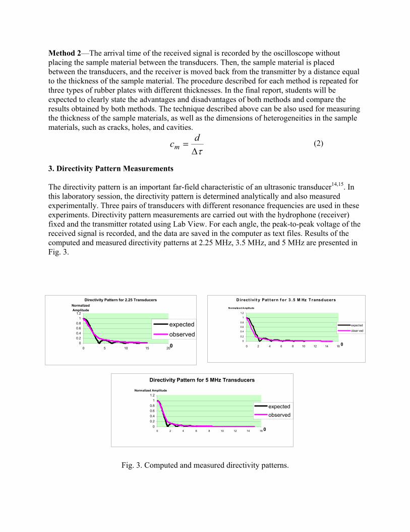
3. Directivity Pattern Measurements
The directivity pattern is an important far-field characteristic of an ultrasonic transducer14,15
. In
this laboratory session, the directivity pattern is determined analytically and also measured
experimentally. Three pairs of transducers with different resonance frequencies are used in these
experiments. Directivity pattern measurements are carried out with the hydrophone (receiver)
fixed and the transmitter rotated using Lab View. For each angle, the peak-to-peak voltage of the
received signal is recorded, and the data are saved in the computer as text files. Results of the
computed and measured directivity patterns at 2.25 MHz, 3.5 MHz, and 5 MHz are presented in
Fig. 3.
D irect ivi t y Pat t ern f o r 3 .5 M Hz T ransducers
0
0.2
0.4
0.6
0.8
1
1.2
0 2 4 6 8 10 12 14 160
Normalized Amplitude
expected
obser ved
Directivity Pattern for 2.25 Transducers
0
0.2
0.4
0.6
0.8
1
1.2
0 5 10 15 200
Normalized
Amplitude
expected
observed
Directivity Pattern for 5 MHz Transducers
0
0.2
0.4
0.6
0.8
1
1.2
0 2 4 6 8 10 12 14 16 0
Normalized Amplitude
expected
observed
Fig. 3. Computed and measured directivity patterns.
4. Measurements of the attenuation coefficient of the ultrasonic waves in Plexiglas
The attenuation of a wave is determined by scattering and absorption, which are properties of the
medium through which the wave passes13,16
. Since the scattering and absorption are frequency
dependent, attenuation can be used in the quality control of the materials. In this laboratory
session, the immersion technique is used for the measurements of the attenuation coefficient in
Plexiglas. Three Plexiglas plates, which have the same mechanical and physical properties and
different thicknesses, are used in the experiments. At least two samples of the Plexiglas are
required for the experiment, since the reflection coefficient of the Plexiglas is not known and
should be eliminated from the evaluation of the attenuation coefficient. The peak-to-peak voltage
of the received signal is recorded by the oscilloscope and is saved in the computer.
Measurements are repeated with two other sets of transducers and the attenuation coefficient in
dB/cm/MHz is determined.
Feedback from the students who took this course indicated that this course has been extremely
effective; this information was recorded in students’ course evaluation forms. Most of the
students indicated that this was one of the best hands-on experiences they have ever had. Such a
positive course evaluation record and willingness to develop quite a unique course for AET
students encourages faculty of the Goodwin College to adapt and implement this laboratory
course with the emphasis in ultrasound NDE of materials, which would benefit manufacturing
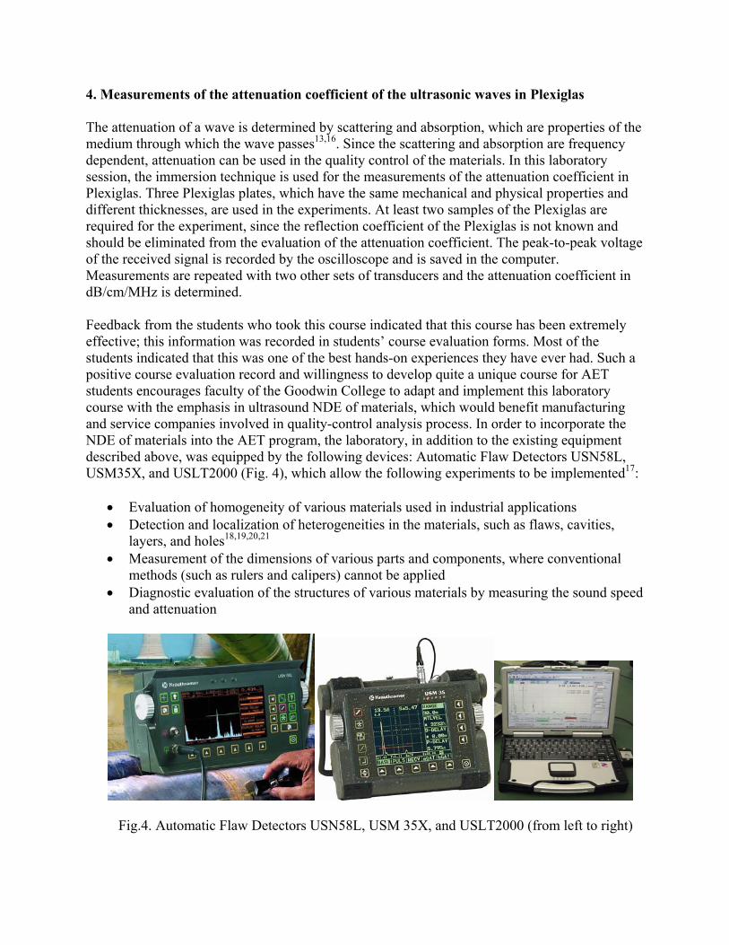
and service companies involved in quality-control analysis process. In order to incorporate the
NDE of materials into the AET program, the laboratory, in addition to the existing equipment
described above, was equipped by the following devices: Automatic Flaw Detectors USN58L,
USM35X, and USLT2000 (Fig. 4), which allow the following experiments to be implemented17
:
‚ Evaluation of homogeneity of various materials used in industrial applications
‚ Detection and localization of heterogeneities in the materials, such as flaws, cavities,
layers, and holes18,19,20,21
‚ Measurement of the dimensions of various parts and components, where conventional
methods (such as rulers and calipers) cannot be applied
‚ Diagnostic evaluation of the structures of various materials by measuring the sound speed
and attenuation
Fig.4. Automatic Flaw Detectors USN58L, USM 35X, and USLT2000 (from left to right)

The first course, MET 380 (NDE of Materials), was offered as a special topic course during the
winter term of the 2005-2006 academic year. Students were engaged in the weekly experiments
using equipment described above, along with newly purchased automatic flaw detectors from GE
Inspection Technologies, such as USN 58 and USM 35. During the laboratory sessions, students
were able to control NDE devices via computers allowing integration of the experiments with
Internet-based automation technologies.
Specifically, the following experiments were carried out:
1. Calibration of the flaw detectors using Straight-Beam probes utilizing the instruments’
AUTO-CAL feature. Straight-beam probes, either single-element probe or dual-element probe,
can be used for material thickness measurements. The description of the experiment using the
USN 58 flaw detector and a dual-element probe is described below. During the procedure,
students set the display RANGE so that two reference calibration echoes from different material
thicknesses (Fig. 5) are displayed on the screen.
Fig.5. Calibration of the flaw detectors using a straight-beam probe
In the CAL Menu, the two calibration reference distances are entered as S-REF1 and S-REF2
with S-REF1 being the thinner reference thickness and S-REF2 being the thicker reference
thickness. The transducer is placed on the THINNER reference and the key is pressed to
record the reading. The recording of the first calibration echo is confirmed by the message
“ECHO is RECORDED”, and the thickness of the calibration block is recorded on the display
(Fig. 6). Then, the transducer is placed on the THICKER reference and the key is pressed.
The recording of the second calibration echo is also confirmed by the message “ECHO is
RECORDED”, and once again the thickness of the calibration block is recorded on the display
(Fig. 7).
Fig. 6. First calibration echo Fig. 7. Second calibration echo

The correct calibration is confirmed y e “CALIBRATION IS DONE”. The flb the m ssage aw
er
uring the calibration procedures, the following rule should be implemented: Use a work piece
2. Wall thickness measurements and the detection of near-to-surface discontinuities (Fig. 8).
Aft
Fig.8. Detection of near-to-surface discontinuities
3. Calibration proc e Verification, Sound
Pat
detector will now automatically determine the sound velocity and probe delay for the transduc
and material being used in this procedure. These values will be set to the corresponding
functions accordingly.
D
of the same material as the test object whose dimensions are known. By coupling the probe onto
an object of known thickness, t, an echo sequence appears on the display.
er the calibration of the instrument, the detection of discontinuities is carried out with the
same instrument and the same probe according to the rule described above.
edure with the Angle-Beam probe for Wedge Angl
h Distance Calibration, and Flaw Sensitivity Calibration using an IIW (International Institute
of Welding) type 1 calibration block is presented below (Fig 9).
Fig. 9. IIW calibration block
sing the flaw detector’s TRIG Menu, the student enters in the following information to set up
dence) 45 through 90 . This value is
b. dge and the Index or Sound
Exit point on the wedge ( X). PD is the Projection Distance.
U
the angle-beam flaw position calculations (Fig. 10):
a. Probe Wedge ANGLE (Angle of Incio o
required for the calculation of the flaw position (S).
X-VALUE is the distance between the probe’s front e

c. MAT THICK is the base material’s wall thickness. This value is required for the
calculation of the Depth Distance, d.
Fig.10. Distance or Sound Path calculations with an Angle Beam Test
o display
flections from sound path distances and sensitivity relationships to side drilled holes.
Students place the transducer at various positions on the IIW block (Fig. 11) t
re
Fig. 11. Calibration with the angle-beam probe for sound Distance and Flaw Sensitivity using an
calibration block
The results of the calibration procedu probe are presented in Fig. 12.
IIW
re using an angle-beam
Fig.12. Results of the calibration procedure using an angle-beam probe

CONCLUSI
winter term of the 2006-2007 academic year (January 2, 2007 – March 23,
007), the newly redesigned course EET-203 (Nondestructive Evaluation of Materials) is being
sing of
its
s
ented the draft of the project and description of the
laboratory experiment to the faculty.
ory
s, and changes.
4. ble for the students.
The spection. For
example, PMT Inc., the local representative of GE Inspection Technology, donated to the AET
h
e classroom sessions. After
ompletion of all laboratory sessions, the students will become familiar with basic acoustical
ll
Students
nal NDE equipment will be purchased and
stalled. Projects and experiments will also be available for the students online. During the
. New
ON
During the current
2
offered to pre-junior AET students. The industrial partners, in collaboration with the faculty,
developed real-world industrial problems. Mr. Tony Midora of Precision Measurement
Technology Inc. participates in providing instruction during the laboratory sessions. The
authentic problems were presented to the faculty who were responsible for the final phra
the given task, such that the description of the task, including the objective of the project,
motivation, and the expected deliverables are clear and understood by the students. Specific step
of faculty-industry collaboration were:
1. The industrial collaborators pres
2. The drafts were reviewed by the faculty and will be presented to the Industrial Advis
Committee for suggestions, correction
3. Drafts were amended and returned to the industrial contacts for their final approval.
Projects, experiments, and manuals are currently availa
industrial collaborators also provided samples of parts and materials used for in
program three parts of a large diameter pipeline, which are used for calibration of flaw detectors
in the NDE of the pipelines. Sonaspection International Inc. supplied the welding samples, whic
are used for detection and characterization of the weld’s defects. Westech Inspection Inc.
provided the sample of a portion of a pipe covered by corrosion.
The work in the laboratory enhances the fundamentals taught in th
c
instrumentation, possess hands-on experience with ultrasonic and electronic equipment, and wi
be able to demonstrate the basic principles of ultrasound imaging and NDE techniques. An
important objective of this laboratory is to improve the students’ knowledge of data gathering,
the identification of sources leading to erroneous measurements, and proficiency in
communication skills. Therefore, a concise written report clearly describing all conclusions and
comments is required within seven days after completion of each laboratory session.
work in teams on projects drawn from several areas of technological interest. The simulation of
the NDE applications used by companies in industry is implemented in the proposed project. A
qualified evaluator from industry will make an evaluation of the success of the course based on
the students’ laboratory reports, the final report, and the final presentation. The students who
demonstrate the level of competence required by industry will receive the certificate of
qualification in ultrasound NDE of materials.
This project is still under development. Additio
in
development of this project, more experiments and case studies will be added to this course
developments will be incorporated into the conference presentation.

REFERENCES
1. R.M Felder and R. Brent. The Intellectual development of Science and Engineering students. Part 2:
ote Growth. Journal of Engineering Education. Vol. 93, No. 4, 2004, p. 279.
g and G. Wheeler. ASNT Level II Study Guide. The American Society for Nondestructive
al
NT Handbook, Vol. 7,
Teaching to Prom
2. W. Spauldin
Testing. 2002.
3. V. Genis, H. Sosa, & E. Radulescu. Ultrasound Measurements and Nondestructive Testing Education
Laboratory. Proceedings of the ASEE Conference, pp. 1-9, June 2004.
4. Workforce 2000: An Annual Report on Greater Philadelphia’s Labor Market.
Workforce 20025. : Measuring what matters. The Reinvestment Fund. October 2002.
6. Pennsylvania Economy League’s Report, Building a World-Class Technical Workforce. Report #686.
D. J. Hagemaier. Ultrasonic Maintenance Testing of Aircraft Structures7. , in AS
American Society for Nondestructive Testing, Columbus, OH, 1991.
8. T.M. Mansour. Ultrasonic Inspection of Spot Welds in Thin-Gage Steel. Mat. Evaluation, Vol. 46, No. 5,
1988, pp. 640-658.
9. E.P. Papadakis. Challenges and Opportunities for Nondestructive Inspection Technology in the High-
Volume Durable Goods Industry. Mat. Evaluation, Vol. 39, No. 2, 1980, pp. 122-130.
10. W. G. Lindsay, W. J. Ion, and G. J. Murdoch. The Virtual Interview, an Exercise in Undergraduate
Support. http://rilw.itim-cj.ro/97/Lindsay.html.
11. Ann Reich and Bob Perry. Videoconferencing in adult education: Challenging the norms.
http://www2.auckland.ac.nz/cpd/HERDSA/HTML/TchLearn/REICH1.HTM.
12. M.A. Breazeale at al. In P.H. Edmonds (Ed), Methods of Experimental Physics, Ultrasonics, Vol. 19,
ic Attenuation.
ods,
.
02.
Academic, New York, 1981, pp.67-135.
13. E.P Papadakis. The Measurement of Ultrasonic Velocity and the Measurements of Ultrason
In R.N. Thurston and A.D. Pierce (Eds), Physical Acoustics, Vol. XIX, Ultrasonic Measurement Meth
Academic, Boston, 1990, pp. 81-106 and 107-155.
14. L.E. Kinsler at al. Fundamentals of Acoustics. Ch. 7. John Wiley & Sons, Inc., Fourth Edition, 2000.
15. E.P Papadakis. Theoretical and experimental Methods to Evaluate Ultrasonic Transducers for Inspection
and Diagnostic Applications. IEEE Trans., Vol. SU-26, 1979, pp. 14-25.
E.P. Papadakis. Ultrasonic Attenuation and velocity16. in Three Transformation Products in Steel. J. Appl
Phys., Vol. 35, 1964, pp. 1474-1482.
17. Dong Fei, David Hsu, and Mark Warchol. Journal of NDE, Vol. 20, No. 3, 2002, pp. 95-112.
18. Nondestructive Testing. Volume I – Basic Principles. General Dynamics. ASNT Publication, 2002.
19. Nondestructive Testing. Volume II – Equipment. General Dynamics. ASNT Publication, 2002.
20. Nondestructive Testing. Volume III – Applications. General Dynamics. ASNT Publication, 20
21. Paul Mix. Introduction to Nondestructive Testing. A Training Guide. A John Wiley & Sons, 2005.