ag 3rw soft starters - · pdf file3rw soft starters 3rw44 for high-feature applications...
TRANSCRIPT
3RW Soft Starters
3RW44for High-Feature applications
6/23Siemens LV 1 N · 04/2007
66
n Function
Equipped with modern, ergonomic user prompting the SIRIUS 3RW44 soft starters can be commissioned quickly and easily using a keypad and a menu-prompted, multi-line display with background lighting. The optimized motor ramp-up and ramp-down can be effected quickly, easily and reliably by means of just a few settings with a selectable language. Four-botton operation and plain-text displays for each menu point guarantee full clarity at every moment of the parameteriza-tion and operation. During operation and when control voltage is applied, the front panel continuously presents measured values and operating values as well as warnings and fault messages. An external display and operator module can be connected by means of a connection cable to the soft starter, thus enabling active indications and the like to be read directly from the control cabinet door.
The SIRIUS 3RW44 soft starters are equipped with optimum functionality. An integral bypass contact system reduces the power loss of the soft starter during operation. This reliably prevents heating of the switchgear environment. The SIRIUS 3RW44 soft starters have internal intrinsic device protection. This prevents thermal overloading of the power section's thyristors, e.g. due to unacceptably high closing operations.
Wiring outlay for installing an additional motor overload relay is no longer needed as the SIRIUS 3RW44 soft starters perform this function too. In addition they offer adjustable trip classes and a thermistor motor protection function. As an option the thyristors can also be protected by SITOR semiconductor fuses from short-circuiting. And even inrush current peaks are reliably avoided thanks to adjustable current limiting.
As a further option the SIRIUS 3RW44 soft starters can be upgraded with a PROFIBUS DP module. Thanks to their commu-nication capability and their programmable control inputs and relay outputs the SIRIUS 3RW44 soft starters can be very easily and quickly integrated in higher-level control system.
In addition a creep speed function is available for positioning and setting jobs. With this function the motor can be controlled in both directions of rotation with reduced torque and an adjustable, low speed.
On the other hand the SIRIUS 3RW44 soft starters offer a new, combined DC braking function for the fast stopping of driving loads.
Highlights• Soft starting with breakaway pulse, torque control or voltage
ramp, adjustable torque or current limiting as well as any combination of these, depending on load type
• Integrated bypass contact system to minimize power loss• Various setting options for the starting parameters such as
starting torque, starting voltage, ramp-up and ramp-down time, and much more in three separate parameter sets
• Start-up detection• Inside-delta circuit for savings in terms of size and equipment
costs• Various ramp-down modes selectable: free ramp-down,
torque-controlled pump ramp-down, combined DC braking• Solid-state motor overload and intrinsic device protection• Thermistor motor protection• Keypad with a menu-controlled, multi-line, graphic display with
background lighting• Interface for communication with the PC for more accurate setting
of the parameters as well as for control and monitoring• Simple adaptation to the motor feeder• Simple mounting and start-up• Display of operating states and fault messages• Connection to PROFIBUS with optional PROFIBUS DP module• External display and operator module• Mains voltages from 200 to 690 V, 50 to 60 Hz• Applicable up to 60 °C (derating from 40 °C)
© Siemens AG 2007
3RW Soft Starters
3RW44 for High-Feature applications
6/24 Siemens LV 1 N · 04/2007
6
n Technical specifications
Type 3RW44 . .-.BC3. 3RW44 . .-.BC4.Terminal
Control electronicsRated valuesRated control supply voltage A1/A2/PE V AC 115 AC 230• Tolerance % -15/+10 -15/+10Rated control supply current STANDBY mA 30 20Rated control supply current ON• 3RW44 2. mA 300 170• 3RW44 3. mA 500 250• 3RW44 4. mA 750 400• 3RW44 5. mA 450 200• 3RW44 6. mA 650 300Maximum current (pickup bypass)• 3RW44 2. mA 1000 500• 3RW44 3. mA 2500 1250• 3RW44 4. mA 6000 3000• 3RW44 5. mA 4500 2500• 3RW44 6. mA 4500 2500Rated frequency Hz 50 ... 60 50 ... 60• Tolerance % ±10 ±10
Type 3RW44 . .Terminal Factory presetting
Control electronicsControl inputsInput 1 IN1 Start motor right parameter set 1Input 2 IN2 No actionInput 3 IN3 No actionInput 4 IN4 Trip resetSupply L+/L-• Rated operational current mA Approx. 10 per input according to
DIN 19240• Rated operational voltage L+ Internal voltage: 24 V DC from internal
supply through terminal L+ to IN1 ... IN4. Maximum load at L+ approx. 55 mA
L- External voltage: DC external voltage (according to DIN 19240) through terminals L- and IN1 ... IN4 (min. 12 V DC, max. 30 V DC)
Thermistor motor protection inputsInputs T1/T2 PTC type A or Thermoclick DeactivatedRelay outputs (floating auxiliary contacts)Output 1 13/14 ON periodOutput 2 23/24 No actionOutput 3 33/34 No actionOutput 4 95/96/98 Group faultSwitching capacity of the relay outputs (auxiliary contacts)230 V/AC-15 A 3 at 240 V24 V/DC-13 A 1 at 24 VProtection against overvoltages Protection by means of varistor through relay contactShort-circuit protection 4 A gL/gG operational class;
6 A quick (fuse is not included in scope of supply)Protection functionsMotor protection functionsTrips in the event of Thermal overloading of the motorTrip class according to IEC 60947-4-1 Class 5/10/15/20/30 10Phase failure sensitivity % >40Overload warning YesReset and recovery Manual/Automatic ManualReset option after tripping Manual/Automatic ManualRecovery time min. 1 ... 30 1Device protection functionsTrips in the event of Thermal overloading of the thyristorsReset option after tripping Manual/Automatic ManualRecovery time min. 0.5Bypass protection functionsTrips in the event of Thermal overloading of the bypass
contactsReset option after tripping ManualRecovery time min. 1
© Siemens AG 2007
3RW Soft Starters
3RW44for High-Feature applications
6/25Siemens LV 1 N · 04/2007
66
1) Max. current limit value for 3RW44 53 ... 3RW44 57: 500 % and for 3RW44 58 ... 3RW44 66 :450 %.
2) Reference variable depends on the motor used but is always smaller than the rated torque of the motor.
Type 3RW44 . .Factory presetting
Control times and parametersControl timesClosing delay (with connected control voltage) ms <50Closing delay (automatic mode) ms <4000Recovery time (closing command in active ramp-down) ms <100Mains failure bridging timeControl supply voltage ms 100Mains failure response timeLoad current circuit ms 100Reclosing lockout after overload tripMotor protection trip min. 1 ... 30 1Device protection trip s 30Setting options for startingVoltage ramp for starting voltage % 20 ... 100 30Torque control for starting torque % 10 ... 100 10Torque control for limit torque % 20 ... 200 150Starting time s 0 ... 360 20Maximum starting time s 1 ... 1000 DeactivatedCurrent limit value % 125 ... 5501) 450Breakaway voltage % 40 ... 100 80Breakaway time s 0 ... 2 DeactivatedMotor heat output % 1 ... 100 20Creep mode Left/Right runningSpeed factor as function of rated speed (n = nrated/factor) 3 ... 21 7Creep torque2) % 20 ... 100 50Setting options for ramp-downTorque control for stopping torque % 10 ... 100 10Ramp-down time s 0 ... 360 10Dynamic braking torque % 20 ... 100 50DC braking torque % 20 ... 100 50Operating indications
Test voltageTest mains phasesReady to startStart activeMotor runningRamp-down activeEmergency start active
Warnings/error signalsMains voltage missingLeading-edge phase errorPhase failure• L1• L2• L3Missing load phase• T1• T2• T3Failure• Contact element 1 (thyristor)• Contact element 2 (thyristor)• Contact element 3 (thyristor)Flash memory faultySupply voltage• Below 75 %• Below 85 %• Over 110 %Current unbalance exceededThermal motor model overloadPrewarning limit exceeded• Motor heating• Time-related trip reserveBypass element defectiveMains voltage too highDevice not namedWrong naming versionCurrent measuring range exceededBypass element protection disconnectionPower section• Overheated• Overheating
© Siemens AG 2007
3RW Soft Starters
3RW44 for High-Feature applications
6/26 Siemens LV 1 N · 04/2007
6
1) Parameter motor left possible only in conjunction with creep mode.
Type 3RW44 ..Factory presetting
Control times and parametersWarnings/error signals (continued)
Temperature sensor• Overload• Open-circuit• Short-circuitGround fault• DetectedConnection abort in manual operating modeMax. number of starts exceededIe-limit value overshoot/undershootHeat sink sensor• Open-circuit• Short-circuitQuick-stop activeSwitch block defectiveIe/class setting not permissibleNo external start-up parameters receivedPAA fault
Control inputsInput 1 Motor right parameter set 1Input 2 No actionInput 3 No actionInput 4 Trip resetParameterizing options for control inputs 1 ... 4 No action
Operating manual modeEmergency startCreep speedQuick-stopTrip resetMotor right parameter set 1Motor left parameter set 11)
Motor right parameter set 2Motor left parameter set 21)
Motor right parameter set 3Motor left parameter set 31)
Relay outputsOutput 1 ON periodOutput 2 No actionOutput 3 No actionOutput 4 Group faultParameterizing options for relay outputs 1 ... 3 No action
PAA output 1PAA output 2Input 1Input 2Input 3Input 4StartingOperation/BypassRamp-downON periodCommand motor onDC braking contactorGroup warningGroup faultBus faultDevice faultPower onReady to start
Motor temperature sensors DeactivatedThermoclickPTC type A
© Siemens AG 2007
3RW Soft Starters
3RW44for High-Feature applications
6/27Siemens LV 1 N · 04/2007
66
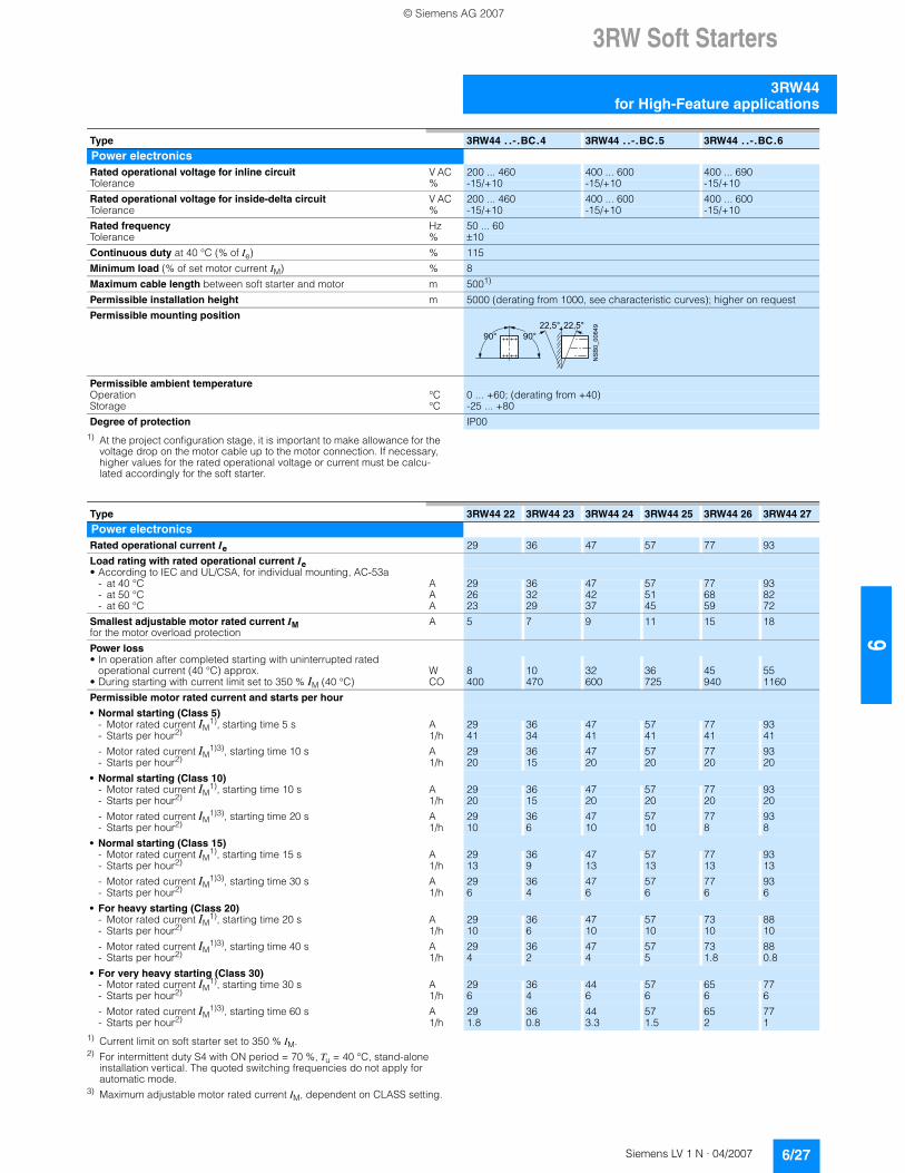
1) At the project configuration stage, it is important to make allowance for the voltage drop on the motor cable up to the motor connection. If necessary, higher values for the rated operational voltage or current must be calcu-lated accordingly for the soft starter.
1) Current limit on soft starter set to 350 % IM.2) For intermittent duty S4 with ON period = 70 %, Tu = 40 °C, stand-alone
installation vertical. The quoted switching frequencies do not apply for automatic mode.
3) Maximum adjustable motor rated current IM, dependent on CLASS setting.
Type 3RW44 . .-.BC.4 3RW44 . .-.BC.5 3RW44 . .-.BC.6
Power electronicsRated operational voltage for inline circuit V AC 200 ... 460 400 ... 600 400 ... 690Tolerance % -15/+10 -15/+10 -15/+10Rated operational voltage for inside-delta circuit V AC 200 ... 460 400 ... 600 400 ... 600Tolerance % -15/+10 -15/+10 -15/+10Rated frequency Hz 50 ... 60Tolerance % ±10Continuous duty at 40 °C (% of Ie) % 115Minimum load (% of set motor current IM) % 8Maximum cable length between soft starter and motor m 5001)
Permissible installation height m 5000 (derating from 1000, see characteristic curves); higher on requestPermissible mounting position
Permissible ambient temperatureOperation °C 0 ... +60; (derating from +40)Storage °C -25 ... +80Degree of protection IP00
NSB0_006492 2 , 5 ° 2 2 , 5 °
9 0 °9 0 °
Type 3RW44 22 3RW44 23 3RW44 24 3RW44 25 3RW44 26 3RW44 27
Power electronicsRated operational current Ie 29 36 47 57 77 93Load rating with rated operational current Ie• According to IEC and UL/CSA, for individual mounting, AC-53a
- at 40 °C A 29 36 47 57 77 93- at 50 °C A 26 32 42 51 68 82- at 60 °C A 23 29 37 45 59 72
Smallest adjustable motor rated current IMfor the motor overload protection
A 5 7 9 11 15 18
Power loss• In operation after completed starting with uninterrupted rated
operational current (40 °C) approx. W 8 10 32 36 45 55• During starting with current limit set to 350 % IM (40 °C) CO 400 470 600 725 940 1160Permissible motor rated current and starts per hour
• Normal starting (Class 5)- Motor rated current IM
1), starting time 5 s A 29 36 47 57 77 93- Starts per hour2) 1/h 41 34 41 41 41 41- Motor rated current IM
1)3), starting time 10 s A 29 36 47 57 77 93- Starts per hour2) 1/h 20 15 20 20 20 20
• Normal starting (Class 10)- Motor rated current IM
1), starting time 10 s A 29 36 47 57 77 93- Starts per hour2) 1/h 20 15 20 20 20 20- Motor rated current IM
1)3), starting time 20 s A 29 36 47 57 77 93- Starts per hour2) 1/h 10 6 10 10 8 8
• Normal starting (Class 15)- Motor rated current IM
1), starting time 15 s A 29 36 47 57 77 93- Starts per hour2) 1/h 13 9 13 13 13 13- Motor rated current IM
1)3), starting time 30 s A 29 36 47 57 77 93- Starts per hour2) 1/h 6 4 6 6 6 6
• For heavy starting (Class 20)- Motor rated current IM
1), starting time 20 s A 29 36 47 57 73 88- Starts per hour2) 1/h 10 6 10 10 10 10- Motor rated current IM
1)3), starting time 40 s A 29 36 47 57 73 88- Starts per hour2) 1/h 4 2 4 5 1.8 0.8
• For very heavy starting (Class 30)- Motor rated current IM
1), starting time 30 s A 29 36 44 57 65 77- Starts per hour2) 1/h 6 4 6 6 6 6- Motor rated current IM
1)3), starting time 60 s A 29 36 44 57 65 77- Starts per hour2) 1/h 1.8 0.8 3.3 1.5 2 1
© Siemens AG 2007

3RW Soft Starters
3RW44 for High-Feature applications
6/28 Siemens LV 1 N · 04/2007
6
1) Current limit on soft starter set to 350 % IM.2) For intermittent duty S4 with ON period = 70 %, Tu = 40 °C, stand-alone
installation vertical. The quoted switching frequencies do not apply for automatic mode.
3) Maximum adjustable motor rated current IM, dependent on CLASS setting.
Type 3RW44 34 3RW44 35 3RW44 36
Power electronicsRated operational current Ie 113 134 162Load rating with rated operational current Ie• According to IEC and UL/CSA, for individual mounting, AC-53a
- at 40 °C A 113 134 162- at 50 °C A 100 117 145- at 60 °C A 88 100 125
Smallest adjustable motor rated current IMfor the motor overload protection
A 22 26 32
Power loss• In operation after completed starting with uninterrupted rated
operational current (40 °C) approx. W 64 76 95• During starting with current limit set to 350 % IM (40 °C) CO 1350 1700 2460Permissible motor rated current and starts per hour
• Normal starting (Class 5)- Motor rated current IM
1), starting time 5 s A 113 134 162- Starts per hour2) 1/h 41 39 41- Motor rated current IM
1)3), starting time 10 s A 113 134 162- Starts per hour2) 1/h 20 15 20
• Normal starting (Class 10)- Motor rated current IM
1), starting time 10 s A 113 134 162- Starts per hour2) 1/h 20 15 20- Motor rated current IM
1)3), starting time 20 s A 113 134 162- Starts per hour2) 1/h 9 6 7
• Normal starting (Class 15)- Motor rated current IM
1), starting time 15 s A 113 134 162- Starts per hour2) 1/h 13 9 12- Motor rated current IM
1)3), starting time 30 s A 113 134 162- Starts per hour2) 1/h 6 6 1
• For heavy starting (Class 20)- Motor rated current IM
1), starting time 20 s A 106 125 147- Starts per hour2) 1/h 9 9 10- Motor rated current IM
1)3), starting time 40 s A 106 125 147- Starts per hour2) 1/h 1.5 2 1
• For very heavy starting (Class 30)- Motor rated current IM
1), starting time 30 s A 91 110 120- Starts per hour2) 1/h 6 6 6- Motor rated current IM
1)3), starting time 60 s A 91 110 120- Starts per hour2) 1/h 2 2 2
© Siemens AG 2007

3RW Soft Starters
3RW44for High-Feature applications
6/29Siemens LV 1 N · 04/2007
66
1) Current limit on soft starter set to 350 % IM.2) For intermittent duty S4 with ON period = 70 %, Tu = 40 °C, stand-alone
installation vertical. The quoted switching frequencies do not apply for automatic mode.
3) Maximum adjustable motor rated current IM, dependent on CLASS setting.
Type 3RW44 43 3RW44 44 3RW44 45 3RW44 46 3RW44 47
Power electronicsRated operational current Ie 203 250 313 356 432Load rating with rated operational current Ie• According to IEC and UL/CSA, for individual mounting, AC-53a
- at 40 °C A 203 250 313 356 432- at 50 °C A 180 215 280 315 385- at 60 °C A 156 185 250 280 335
Smallest adjustable motor rated current IMfor the motor overload protection
A 40 50 62 71 86
Power loss• In operation after completed starting with uninterrupted rated
operational current (40 °C) approx. W 89 110 145 174 232• During starting with current limit set to 350 % IM (40 °C) CO 3350 4000 4470 5350 5860Permissible motor rated current and starts per hour
• Normal starting (Class 5)- Motor rated current IM
1), starting time 5 s A 203 250 313 356 432- Starts per hour2) 1/h 41 41 41 41 39- Motor rated current IM
1)3), starting time 10 s A 203 250 313 356 432- Starts per hour2) 1/h 20 20 19 17 16
• Normal starting (Class 10)- Motor rated current IM
1), starting time 10 s A 203 250 313 356 432- Starts per hour2) 1/h 20 20 19 17 16- Motor rated current IM
1)3), starting time 20 s A 203 250 313 356 432- Starts per hour2) 1/h 9 10 6 4 5
• Normal starting (Class 15)- Motor rated current IM
1), starting time 15 s A 203 240 313 325 402- Starts per hour2) 1/h 13 13 10 13 11- Motor rated current IM
1)3), starting time 30 s A 203 240 313 325 402- Starts per hour2) 1/h 3 6 1 2 1
• For heavy starting (Class 20)- Motor rated current IM
1), starting time 20 s A 195 215 275 285 356- Starts per hour2) 1/h 10 10 10 10 10- Motor rated current IM
1)3), starting time 40 s A 195 215 275 285 356- Starts per hour2) 1/h 1 5 1 3 1
• For very heavy starting (Class 30)- Motor rated current IM
1), starting time 30 s A 162 180 220 240 285- Starts per hour2) 1/h 6 6 6 6 6- Motor rated current IM
1)3), starting time 60 s A 162 180 220 240 285- Starts per hour2) 1/h 3 3 3 2 1
© Siemens AG 2007

3RW Soft Starters
3RW44 for High-Feature applications
6/30 Siemens LV 1 N · 04/2007
6
1) Current limit on soft starter set to 350 % IM.2) For intermittent duty S4 with ON period = 70 %, Tu = 40 °C, stand-alone
installation vertical. The quoted switching frequencies do not apply for automatic mode.
3) Maximum adjustable motor rated current IM, dependent on CLASS setting.
Type 3RW44 53 3RW44 54 3RW44 55 3RW44 56 3RW44 57 3RW44 58
Power electronicsRated operational current Ie 551 615 693 780 880 970Load rating with rated operational current Ie• According to IEC and UL/CSA, for individual mounting, AC-53a
- at 40 °C A 551 615 693 780 880 970- at 50 °C A 494 551 615 693 780 850- at 60 °C A 438 489 551 615 693 760
Smallest adjustable motor rated current IMfor the motor overload protection
A 110 123 138 156 176 194
Power loss• In operation after completed starting with uninterrupted rated
operational current (40 °C) approx. W 159 186 220 214 250 270• During starting with current limit set to 350 % IM (40 °C) CO 7020 8100 9500 11100 13100 15000Permissible motor rated current and starts per hour
• Normal starting (Class 5)- Motor rated current IM
1), starting time 5 s A 551 615 693 780 880 970- Starts per hour2) 1/h 41 41 37 33 22 17- Motor rated current IM
1)3), starting time 10 s A 551 615 693 780 880 970- Starts per hour2) 1/h 20 20 16 13 8 5
• Normal starting (Class 10)- Motor rated current IM
1), starting time 10 s A 551 615 693 780 880 970- Starts per hour2) 1/h 20 20 16 13 8 5- Motor rated current IM
1)3), starting time 20 s A 551 615 693 780 880 970- Starts per hour2) 1/h 10 9 6 4 0.3 0.3
• Normal starting (Class 15)- Motor rated current IM
1), starting time 15 s A 551 615 666 723 780 821- Starts per hour2) 1/h 13 13 11 9 8 8- Motor rated current IM
1)3), starting time 30 s A 551 615 666 723 780 821- Starts per hour2) 1/h 6 4 3 1 0.4 0.5
• For heavy starting (Class 20)- Motor rated current IM
1), starting time 20 s A 551 591 633 670 710 740- Starts per hour2) 1/h 10 10 7 8 8 9- Motor rated current IM
1)3), starting time 40 s A 551 591 633 670 710 740- Starts per hour2) 1/h 4 2 1 1 0.4 1
• For very heavy starting (Class 30)- Motor rated current IM
1), starting time 30 s A 500 525 551 575 600 630- Starts per hour2) 1/h 6 6 6 6 6 6- Motor rated current IM
1)3), starting time 60 s A 500 525 551 575 600 630- Starts per hour2) 1/h 2 1 1 1 1.5 1
© Siemens AG 2007
3RW Soft Starters
3RW44for High-Feature applications
6/31Siemens LV 1 N · 04/2007
66
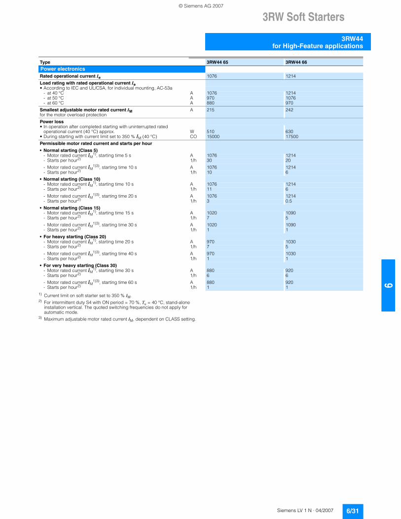
1) Current limit on soft starter set to 350 % IM.2) For intermittent duty S4 with ON period = 70 %, Tu = 40 °C, stand-alone
installation vertical. The quoted switching frequencies do not apply for automatic mode.
3) Maximum adjustable motor rated current IM, dependent on CLASS setting.
Type 3RW44 65 3RW44 66
Power electronicsRated operational current Ie 1076 1214Load rating with rated operational current Ie• According to IEC and UL/CSA, for individual mounting, AC-53a
- at 40 °C A 1076 1214- at 50 °C A 970 1076- at 60 °C A 880 970
Smallest adjustable motor rated current IMfor the motor overload protection
A 215 242
Power loss• In operation after completed starting with uninterrupted rated
operational current (40 °C) approx. W 510 630• During starting with current limit set to 350 % IM (40 °C) CO 15000 17500Permissible motor rated current and starts per hour
• Normal starting (Class 5)- Motor rated current IM
1), starting time 5 s A 1076 1214- Starts per hour2) 1/h 30 20- Motor rated current IM
1)3), starting time 10 s A 1076 1214- Starts per hour2) 1/h 10 6
• Normal starting (Class 10)- Motor rated current IM
1), starting time 10 s A 1076 1214- Starts per hour2) 1/h 11 6- Motor rated current IM
1)3), starting time 20 s A 1076 1214- Starts per hour2) 1/h 3 0.5
• Normal starting (Class 15)- Motor rated current IM
1), starting time 15 s A 1020 1090- Starts per hour2) 1/h 7 5- Motor rated current IM
1)3), starting time 30 s A 1020 1090- Starts per hour2) 1/h 1 1
• For heavy starting (Class 20)- Motor rated current IM
1), starting time 20 s A 970 1030- Starts per hour2) 1/h 7 5- Motor rated current IM
1)3), starting time 40 s A 970 1030- Starts per hour2) 1/h 1 1
• For very heavy starting (Class 30)- Motor rated current IM
1), starting time 30 s A 880 920- Starts per hour2) 1/h 6 6- Motor rated current IM
1)3), starting time 60 s A 880 920- Starts per hour2) 1/h 1 1
© Siemens AG 2007
3RW Soft Starters
3RW44 for High-Feature applications
6/32 Siemens LV 1 N · 04/2007
6
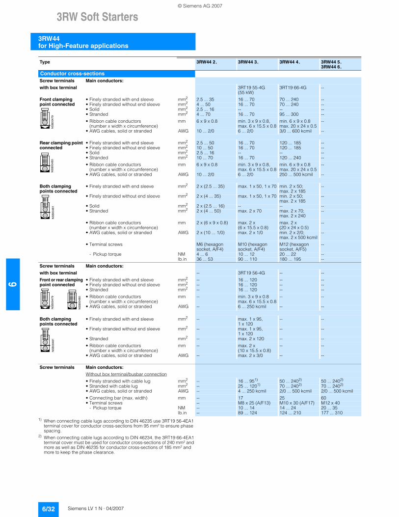
1) When connecting cable lugs according to DIN 46235 use 3RT19 56-4EA1 terminal cover for conductor cross-sections from 95 mm² to ensure phase spacing.
2) When connecting cable lugs according to DIN 46234, the 3RT19 66-4EA1 terminal cover must be used for conductor cross-sections of 240 mm² and more as well as DIN 46235 for conductor cross-sections of 185 mm² and more to keep the phase clearance.
Type 3RW44 2. 3RW44 3. 3RW44 4. 3RW44 5. 3RW44 6.
Conductor cross-sectionsScrew terminals Main conductors:
with box terminal 3RT19 55-4G (55 kW)
3RT19 66-4G --
Front clamping point connected
• Finely stranded with end sleeve mm2 2.5 ... 35 16 ... 70 70 ... 240 --• Finely stranded without end sleeve mm2 4 ... 50 16 ... 70 70 ... 240 --• Solid mm2 2.5 ... 16 -- -- --• Stranded mm2 4 ... 70 16 ... 70 95 ... 300 --• Ribbon cable conductors
(number x width x circumference)mm 6 x 9 x 0.8 min. 3 x 9 x 0.8,
max. 6 x 15.5 x 0.8min. 6 x 9 x 0.8max. 20 x 24 x 0.5
--
• AWG cables, solid or stranded AWG 10 ... 2/0 6 ... 2/0 3/0 ... 600 kcmil --
Rear clamping point connected
• Finely stranded with end sleeve mm2 2.5 ... 50 16 ... 70 120 ... 185 --• Finely stranded without end sleeve mm2 10 ... 50 16 ... 70 120 ... 185 --• Solid mm2 2.5 ... 16 -- -- --• Stranded mm2 10 ... 70 16 ... 70 120 ... 240 --• Ribbon cable conductors
(number x width x circumference)mm 6 x 9 x 0.8 min. 3 x 9 x 0.8,
max. 6 x 15.5 x 0.8min. 6 x 9 x 0.8max. 20 x 24 x 0.5
--
• AWG cables, solid or stranded AWG 10 ... 2/0 6 ... 2/0 250 ... 500 kcmil --
Both clamping points connected
• Finely stranded with end sleeve mm2 2 x (2.5 ... 35) max. 1 x 50, 1 x 70 min. 2 x 50; max. 2 x 185
--
• Finely stranded without end sleeve mm2 2 x (4 ... 35) max. 1 x 50, 1 x 70 min. 2 x 50; max. 2 x 185
--
• Solid mm2 2 x (2.5 ... 16) -- -- --• Stranded mm2 2 x (4 ... 50) max. 2 x 70 max. 2 x 70;
max. 2 x 240--
• Ribbon cable conductors (number x width x circumference)
mm 2 x (6 x 9 x 0.8) max. 2 x(6 x 15.5 x 0.8)
max. 2 x(20 x 24 x 0.5)
--
• AWG cables, solid or stranded AWG 2 x (10 ... 1/0) max. 2 x 1/0 min. 2 x 2/0; max. 2 x 500 kcmil
--
• Terminal screws M6 (hexagon socket, A/F4)
M10 (hexagon socket, A/F4)
M12 (hexagon socket, A/F5)
--
- Pickup torque NM 4 ... 6 10 ... 12 20 ... 22 --lb.in 36 ... 53 90 ... 110 180 ... 195 --
Screw terminals Main conductors:
with box terminal -- 3RT19 56-4G -- --Front or rear clampingpoint connected
• Finely stranded with end sleeve mm2 -- 16 ... 120 -- --• Finely stranded without end sleeve mm2 -- 16 ... 120 -- --• Stranded mm2 -- 16 ... 120 -- --• Ribbon cable conductors
(number x width x circumference)mm -- min. 3 x 9 x 0.8
max. 6 x 15.5 x 0.8-- --
• AWG cables, solid or stranded AWG -- 6 ... 250 kcmil -- --
Both clamping points connected
• Finely stranded with end sleeve mm2 -- max. 1 x 95, 1 x 120
-- --
• Finely stranded without end sleeve mm2 -- max. 1 x 95, 1 x 120
-- --
• Stranded mm2 -- max. 2 x 120 -- --• Ribbon cable conductors
(number x width x circumference)mm -- max. 2 x
(10 x 15.5 x 0.8)-- --
• AWG cables, solid or stranded AWG -- max. 2 x 3/0 -- --
Screw terminals Main conductors:
Without box terminal/busbar connection• Finely stranded with cable lug mm2 -- 16 ... 951) 50 ... 2402) 50 ... 2402)
• Stranded with cable lug mm2 -- 25 ... 1201) 70 ... 2402) 70 ... 2402)
• AWG cables, solid or stranded AWG -- 4 ... 250 kcmil 2/0 ... 500 kcmil 2/0 ... 500 kcmil• Connecting bar (max. width) mm -- 17 25 60• Terminal screws -- M8 x 25 (A/F13) M10 x 30 (A/F17) M12 x 40
- Pickup torque NM -- 10 ... 14 14 ... 24 20 ... 35lb.in -- 89 ... 124 124 ... 210 177 ... 310
NSB00479
NSB00480
NSB00481
NSB00479
NSB00480
NSB00481
© Siemens AG 2007
3RW Soft Starters
3RW44for High-Feature applications
6/33Siemens LV 1 N · 04/2007
66
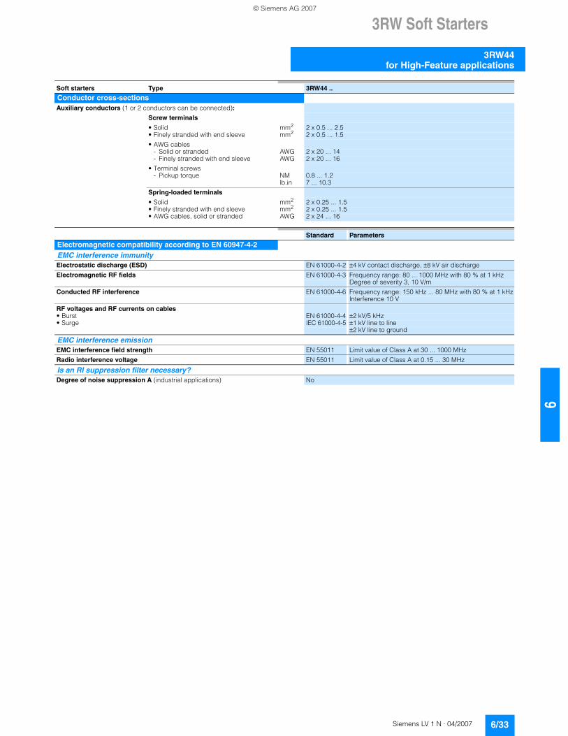
Soft starters Type 3RW44 ..
Conductor cross-sectionsAuxiliary conductors (1 or 2 conductors can be connected):
Screw terminals
• Solid mm2 2 x 0.5 ... 2.5• Finely stranded with end sleeve mm2 2 x 0.5 ... 1.5• AWG cables
- Solid or stranded AWG 2 x 20 ... 14- Finely stranded with end sleeve AWG 2 x 20 ... 16
• Terminal screws- Pickup torque NM 0.8 ... 1.2
lb.in 7 ... 10.3Spring-loaded terminals
• Solid mm2 2 x 0.25 ... 1.5• Finely stranded with end sleeve mm2 2 x 0.25 ... 1.5• AWG cables, solid or stranded AWG 2 x 24 ... 16
Standard Parameters
Electromagnetic compatibility according to EN 60947-4-2EMC interference immunity Electrostatic discharge (ESD) EN 61000-4-2 ±4 kV contact discharge, ±8 kV air dischargeElectromagnetic RF fields EN 61000-4-3 Frequency range: 80 ... 1000 MHz with 80 % at 1 kHz
Degree of severity 3, 10 V/mConducted RF interference EN 61000-4-6 Frequency range: 150 kHz ... 80 MHz with 80 % at 1 kHz
Interference 10 VRF voltages and RF currents on cables• Burst EN 61000-4-4 ±2 kV/5 kHz• Surge IEC 61000-4-5 ±1 kV line to line
±2 kV line to ground
EMC interference emission EMC interference field strength EN 55011 Limit value of Class A at 30 ... 1000 MHzRadio interference voltage EN 55011 Limit value of Class A at 0.15 ... 30 MHz
Is an RI suppression filter necessary?Degree of noise suppression A (industrial applications) No
© Siemens AG 2007
3RW Soft Starters
3RW44 for High-Feature applications
6/34 Siemens LV 1 N · 04/2007
6
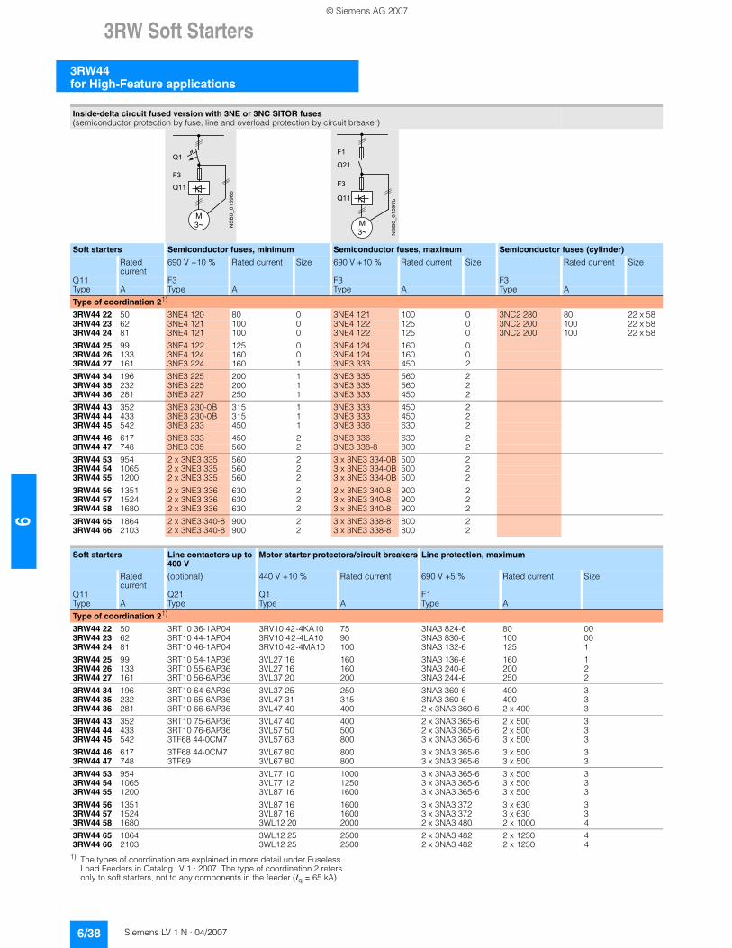
Fuse assignment
The type of coordination to which the motor feeder with soft starter is mounted depends on the application-specific require-ments. Normally, fuseless mounting (combination of motor starter protector and soft starter) is sufficient. If type of coordina-tion 2 is to be fulfilled, semiconductor fuses must be fitted in the motor feeder.
1) The motor rated current must be considered when selecting the devices.2) The types of coordination are explained in more detail under Fuseless
Load Feeders in Catalog LV 1 · 2007.
Inline circuit fuseless version
Soft starters Motor starter protectors/Circuit breakers1)
Rated current 440 V +10 % Rated currentQ11 Q1Type A Type AType of coordination 12): 3RW44 22 ... 3RW44 27: Iq = 32 kA; 3RW44 34 and 3RW44 35: Iq = 16 kA; 3RW44 36 ... 3RW44 66: Iq = 65 kA
3RW44 22 29 3RV10 42-4HA10 503RW44 23 36 3RV10 42-4JA10 633RW44 24 47 3RV10 42-4KA10 753RW44 25 57 3RV10 42-4LA10 903RW44 26 77 3RV10 42-4MA10 1003RW44 27 93 3RV10 42-4MA10 1003RW44 34 113 3VL17 16-2DD36 1603RW44 35 134 3VL17 16-2DD36 1603RW44 36 162 3VL37 25-2DC36 2503RW44 43 203 3VL47 31-3DC36 3153RW44 44 250 3VL47 31-3DC36 3153RW44 45 313 3VL47 40-3DC36 4003RW44 46 356 3VL47 40-3DC36 4003RW44 47 432 3VL57 50-3DC36 5003RW44 53 551 3VL67 80-3AB36 8003RW44 54 615 3VL67 80-3AB36 8003RW44 55 693 3VL67 80-3AB36 8003RW44 56 780 3VL77 10-3AB36 10003RW44 57 880 3VL77 10-3AB36 10003RW44 58 970 3VL77 12-3AB36 12503RW44 65 1076 3VL77 12-3AB36 12503RW44 66 1214 3VL77 12-3AB36 1250
Q 1 1NSB0_01016b
M
3 ~
Q 1
© Siemens AG 2007
3RW Soft Starters
3RW44for High-Feature applications
6/35Siemens LV 1 N · 04/2007
66
1) If the ramp-down function "Combined braking" is selected, no braking contactor is required. If the ramp-down function "DC braking" is selected, a braking contactor must be used in addition (see table for type).For applications with large centrifugal masses (JLoad > JMotor) we recommend the function "DC braking".
2) Additional auxiliary relay K4: LZX:RT4A4T30(3RW44 soft starter with rated control supply voltage 230 V AC),LZX:RT4A4S15(3RW44 soft starter with rated control supply voltage 115 V AC).
3) The types of coordination are explained in more detail under Fuseless Load Feeders in Catalog LV 1 · 2007.
Inline circuit fused version (line protection only)
Soft starters Line protection, maximum Line contactors up to 400 V
Braking contactors1)2)
Rated current 690 V +5 % Rated current Size (optional) (for typical circuit see page 6/47)Q11 F1 Q21 Q91 Q92Type A Type A Type Type TypeType of coordination 13): Iq = 65 kA
3RW44 22 29 3NA3 820-6 50 00 3RT10 34 3RT15 26 --3RW44 23 36 3NA3 822-6 63 00 3RT10 35 3RT15 26 --3RW44 24 47 3NA3 824-6 80 00 3RT10 36 3RT15 35 --3RW44 25 57 3NA3 830-6 100 00 3RT10 44 3RT15 35 --3RW44 26 77 3NA3 132-6 125 1 3RT10 45 3RT10 24 3RT10 353RW44 27 93 3NA3 136-6 160 1 3RT10 46 3RT10 25 3RT10 363RW44 34 113 3NA3 244-6 250 2 3RT10 54 3RT10 34 3RT10 443RW44 35 134 3NA3 244-6 250 2 3RT10 55 3RT10 36 3RT10 453RW44 36 162 3NA3 365-6 500 3 3RT10 56 3RT10 44 3RT10 453RW44 43 203 2 x 3NA3 354-6 2 x 355 3 3RT10 64 3RT10 44 3RT10 543RW44 44 250 2 x 3NA3 354-6 2 x 355 3 3RT10 65 3RT10 44 3RT10 553RW44 45 313 2 x 3NA3 365-6 2 x 500 3 3RT10 75 3RT10 54 3RT10 563RW44 46 356 2 x 3NA3 365-6 2 x 500 3 3RT10 75 3RT10 54 3RT10 563RW44 47 432 2 x 3NA3 365-6 2 x 500 3 3RT10 76 3RT10 55 3RT10 643RW44 53 551 2 x 3NA3 365-6 2 x 500 3 3TF68 3RT10 64 3RT10 663RW44 54 615 2 x 3NA3 365-6 2 x 500 3 3TF68 3RT10 64 3RT10 753RW44 55 693 2 x 3NA3 365-6 2 x 500 3 3TF69 3RT10 65 3RT10 753RW44 56 780 2 x 3NA3 365-6 2 x 500 3 3TF69 3RT10 65 3RT10 753RW44 57 880 2 x 3NA3 365-6 2 x 500 3 3RT10 75 3RT10 763RW44 58 970 3 x 3NA3 365-6 3 x 500 3 3RT10 75 3RT10 763RW44 65 1076 3 x 3NA3 365-6 3 x 500 3 3RT10 75 3TF683RW44 66 1214 3 x 3NA3 365-6 3 x 500 3 3RT10 76 3TF68
F 1
NSB0_01477b
M
3 ~
Q 2 1
Q 1 1
© Siemens AG 2007
3RW Soft Starters
3RW44 for High-Feature applications
6/36 Siemens LV 1 N · 04/2007
6
1) If the ramp-down function "Combined braking" is selected, no braking contactor is required. If the ramp-down function "DC braking" is selected, a braking contactor must be used in addition (see table for type).For applications with large centrifugal masses (JLoad > JMotor) we recommend the function "DC braking".
2) Additional auxiliary relay K4: LZX:RT4A4T30(3RW44 soft starter with rated control supply voltage 230 V AC),LZX:RT4A4S15(3RW44 soft starter with rated control supply voltage 115 V AC).
3) The types of coordination are explained in more detail under Fuseless Load Feeders in Catalog LV 1 · 2007. The type of coordination 2 refers only to soft starters, not to any components in the feeder (Iq = 65 kA).
Inline circuit fused version with 3NE1 SITOR all-range fuse (semiconductor and line protection)
Soft starters All-range fuses Line contactors up to 400 V
Braking contactors1)2)
Rated current
Rated current Voltage Size (optional) (for typical circuit see page 6/47)
Q11 F'1 Q21 Q91 Q92Type A Type A V Type Type TypeType of coordination 23): Iq = 65 kA
3RW44 22 29 3NE1 020-2 80 690 +5 % 00 3RT10 34 3RT15 26 --3RW44 23 36 3NE1 020-2 80 690 +5 % 00 3RT10 35 3RT15 26 --3RW44 24 47 3NE1 021-2 100 690 +5 % 00 3RT10 36 3RT15 35 --3RW44 25 57 3NE1 022-2 125 690 +5 % 00 3RT10 44 3RT15 35 --3RW44 26 77 3NE1 022-2 125 690 +5 % 00 3RT10 45 3RT10 24 3RT10 353RW44 27 93 3NE1 024-2 160 690 +5 % 1 3RT10 46 3RT10 25 3RT10 363RW44 34 113 3NE1 225-2 200 690 +5 % 1 3RT10 54 3RT10 34 3RT10 443RW44 35 134 3NE1 227-2 250 690 +5 % 1 3RT10 55 3RT10 36 3RT10 453RW44 36 162 3NE1 227-2 250 690 +5 % 1 3RT10 56 3RT10 44 3RT10 453RW44 43 203 3NE1 230-2 315 600 +10 % 1 3RT10 64 3RT10 44 3RT10 543RW44 44 250 3NE1 331-2 350 460 +10 % 2 3RT10 65 3RT10 44 3RT10 553RW44 45 313 3NE1 333-2 450 690 +5 % 2 3RT10 75 3RT10 54 3RT10 563RW44 46 356 3NE1 334-2 500 690 +5 % 2 3RT10 75 3RT10 54 3RT10 563RW44 47 432 3NE1 435-2 560 690 +5 % 3 3RT10 76 3RT10 55 3RT10 643RW44 53 551 2 x 3NE1 334-2 500 690 +10 % 2 3TF68 3RT10 64 3RT10 663RW44 54 615 2 x 3NE1 334-2 500 690 +10 % 2 3TF68 3RT10 64 3RT10 753RW44 55 693 2 x 3NE1 334-2 500 690 +10 % 2 3TF69 3RT10 65 3RT10 753RW44 56 780 2 x 3NE1 435-2 560 690 +10 % 3 3TF69 3RT10 65 3RT10 753RW44 57 880 2 x 3NE1 435-2 560 690 +10 % 3 3RT10 75 3RT10 763RW44 58 970 2 x 3NE1 435-2 560 690 +10 % 3 3RT10 75 3RT10 763RW44 65 1076 3 x 3NE1 334-2 500 690 +10 % 2 3RT10 75 3TF683RW44 66 1214 3 x 3NE1 435-2 560 690 +10 % 3 3RT10 76 3TF68
NSB0_01478c
M
3 ~
Q 2 1
Q 1 1
F ´ 1
© Siemens AG 2007
3RW Soft Starters
3RW44for High-Feature applications
6/37Siemens LV 1 N · 04/2007
66
1) If the ramp-down function "Combined braking" is selected, no braking contactor is required. If the ramp-down function "DC braking" is selected, a braking con-tactor must be used in addition (see table for type). For applications with large centrifugal masses (JLoad > JMotor) we recommend the function "DC braking".
2) Additional auxiliary relay K4: LZX:RT4A4T30 (3RW44 soft starter with rated control supply voltage 230 V AC), LZX:RT4A4S15 (3RW44 soft starter with rated control supply voltage 115 V AC).
3) The types of coordination are explained in more detail under Fuseless Load Feeders in Catalog LV 1 · 2007. The type of coordination 2 refers only to soft starters, not to any components in the feeder (Iq = 65 kA).
Inline circuit fused version with 3NE or 3NC SITOR semiconductor fuse(semiconductor protection by fuse, line and overload protection by circuit breaker)
Soft starters Semiconductor fuses, minimum Semiconductor fuses, maximum Semiconductor fuses (cylinder)
Rated current
690 V +10 % Rated current Size 690 V +10 % Rated current
Size Rated current Size
Q11 F3 F3 F3Type A Type A Type A Type AType of coordination 23): Iq = 65 kA
3RW44 22 29 3NE4 120 80 0 3NE4 121 100 0 3NC2 280 80 22 x 583RW44 23 36 3NE4 121 100 0 3NE4 122 125 0 3NC2 200 100 22 x 583RW44 24 47 3NE4 121 100 0 3NE4 122 125 0 3NC2 200 100 22 x 583RW44 25 57 3NE4 122 125 0 3NE4 124 160 03RW44 26 77 3NE4 124 160 0 3NE4 124 160 03RW44 27 93 3NE3 224 160 1 3NE3 333 450 23RW44 34 113 3NE3 225 200 1 3NE3 335 560 23RW44 35 134 3NE3 225 200 1 3NE3 335 560 23RW44 36 162 3NE3 227 250 1 3NE3 333 450 23RW44 43 203 3NE3 230-0B 315 1 3NE3 333 450 23RW44 44 250 3NE3 230-0B 315 1 3NE3 333 450 23RW44 45 313 3NE3 233 450 1 3NE3 336 630 23RW44 46 356 3NE3 333 450 2 3NE3 336 630 23RW44 47 432 3NE3 335 560 2 3NE3 338-8 800 23RW44 53 551 2 x 3NE3 335 560 2 3 x 3NE3 334-0B 500 23RW44 54 615 2 x 3NE3 335 560 2 3 x 3NE3 334-0B 500 23RW44 55 693 2 x 3NE3 335 560 2 3 x 3NE3 334-0B 500 23RW44 56 780 2 x 3NE3 336 630 2 2 x 3NE3 340-8 900 23RW44 57 880 2 x 3NE3 336 630 2 2 x 3NE3 340-8 900 23RW44 58 970 2 x 3NE3 336 630 2 2 x 3NE3 340-8 900 23RW44 65 1076 2 x 3NE3 340-8 900 2 3 x 3NE3 338-8 800 23RW44 66 1214 2 x 3NE3 340-8 900 2 3 x 3NE3 338-8 800 2
Soft starters Line contactors up to 400 V
Braking contactors1)2) Motor starter protectors/circuit breakers
Line protection, maximum
Rated current
(optional) (for typical circuit see page 6/47) 440 V +10 % Rated current
690 V +5 % Rated current Size
Q11 Q21 Q91 Q92 Q1 F1Type A Type Type Type Type A Type AType of coordination 23): Iq = 65 kA
3RW44 22 29 3RT10 34 3RT15 26 -- 3RV10 41-4HA10 50 3NA3 820-6 50 003RW44 23 36 3RT10 35 3RT15 26 -- 3RV10 41-4JA10 63 3NA3 822-6 63 003RW44 24 47 3RT10 36 3RT15 35 -- 3RV10 41-4KA10 75 3NA3 824-6 80 003RW44 25 57 3RT10 44 3RT15 35 -- 3RV10 41-4LA10 90 3NA3 830-6 100 003RW44 26 77 3RT10 45 3RT10 24 3RT10 35 3RV10 41-4MA10 100 3NA3 132-6 125 13RW44 27 93 3RT10 46 3RT10 25 3RT10 36 3RV10 41-4MA10 100 3NA3 136-6 160 13RW44 34 113 3RT10 54 3RT10 34 3RT10 44 3VL17 16-1DD36 160 3NA3 244-6 250 23RW44 35 134 3RT10 55 3RT10 36 3RT10 45 3VL17 16-1DD36 160 3NA3 244-6 250 23RW44 36 162 3RT10 56 3RT10 44 3RT10 45 3VL37 25-1DC36 250 3NA3 365-6 500 33RW44 43 203 3RT10 64 3RT10 44 3RT10 54 3VL47 31-1DC36 315 2 x 3NA3 354-6 2 x 355 33RW44 44 250 3RT10 65 3RT10 44 3RT10 55 3VL47 31-1DC36 315 2 x 3NA3 354-6 2 x 355 33RW44 45 313 3RT10 75 3RT10 54 3RT10 56 3VL47 40-1DC36 400 2 x 3NA3 365-6 2 x 500 33RW44 46 356 3RT10 75 3RT10 54 3RT10 56 3VL47 40-1DC36 400 2 x 3NA3 365-6 2 x 500 33RW44 47 432 3RT10 76 3RT10 55 3RT10 64 3VL57 50-1DC36 500 2 x 3NA3 365-6 2 x 500 33RW44 53 551 3TF68 3RT10 64 3RT10 66 3VL67 80-1AB36 800 2 x 3NA3 365-6 2 x 500 33RW44 54 615 3TF68 3RT10 64 3RT10 75 3VL67 80-1AB36 800 2 x 3NA3 365-6 2 x 500 33RW44 55 693 3TF69 3RT10 65 3RT10 75 3VL67 80-1AB36 800 2 x 3NA3 365-6 2 x 500 33RW44 56 780 3TF69 3RT10 65 3RT10 75 3VL77 10-1AB36 1000 2 x 3NA3 365-6 2 x 500 33RW44 57 880 3RT10 75 3RT10 76 3VL77 10-1AB36 1000 2 x 3NA3 365-6 2 x 500 33RW44 58 970 3RT10 75 3RT10 76 3VL77 12-1AB36 1200 3 x 3NA3 365-6 3 x 500 33RW44 65 1076 3RT10 75 3TF68 3 x 3NA3 365-6 3 x 500 33RW44 66 1214 3RT10 76 3TF68 3 x 3NA3 365-6 3 x 500 3
F 3
NSB0_01019b
Q 1 1
Q 1
M
3 ~
F 1
NSB0_01479b
M
3 ~
Q 2 1
Q 1 1
F 3
© Siemens AG 2007
3RW Soft Starters
3RW44 for High-Feature applications
6/38 Siemens LV 1 N · 04/2007
6
1) The types of coordination are explained in more detail under Fuseless Load Feeders in Catalog LV 1 · 2007. The type of coordination 2 refers only to soft starters, not to any components in the feeder (Iq = 65 kA).
Inside-delta circuit fused version with 3NE or 3NC SITOR fuses(semiconductor protection by fuse, line and overload protection by circuit breaker)
Soft starters Semiconductor fuses, minimum Semiconductor fuses, maximum Semiconductor fuses (cylinder)
Rated current
690 V +10 % Rated current Size 690 V +10 % Rated current Size Rated current Size
Q11 F3 F3 F3Type A Type A Type A Type AType of coordination 21)
3RW44 22 50 3NE4 120 80 0 3NE4 121 100 0 3NC2 280 80 22 x 583RW44 23 62 3NE4 121 100 0 3NE4 122 125 0 3NC2 200 100 22 x 583RW44 24 81 3NE4 121 100 0 3NE4 122 125 0 3NC2 200 100 22 x 583RW44 25 99 3NE4 122 125 0 3NE4 124 160 03RW44 26 133 3NE4 124 160 0 3NE4 124 160 03RW44 27 161 3NE3 224 160 1 3NE3 333 450 23RW44 34 196 3NE3 225 200 1 3NE3 335 560 23RW44 35 232 3NE3 225 200 1 3NE3 335 560 23RW44 36 281 3NE3 227 250 1 3NE3 333 450 23RW44 43 352 3NE3 230-0B 315 1 3NE3 333 450 23RW44 44 433 3NE3 230-0B 315 1 3NE3 333 450 23RW44 45 542 3NE3 233 450 1 3NE3 336 630 23RW44 46 617 3NE3 333 450 2 3NE3 336 630 23RW44 47 748 3NE3 335 560 2 3NE3 338-8 800 23RW44 53 954 2 x 3NE3 335 560 2 3 x 3NE3 334-0B 500 23RW44 54 1065 2 x 3NE3 335 560 2 3 x 3NE3 334-0B 500 23RW44 55 1200 2 x 3NE3 335 560 2 3 x 3NE3 334-0B 500 23RW44 56 1351 2 x 3NE3 336 630 2 2 x 3NE3 340-8 900 23RW44 57 1524 2 x 3NE3 336 630 2 3 x 3NE3 340-8 900 23RW44 58 1680 2 x 3NE3 336 630 2 3 x 3NE3 340-8 900 23RW44 65 1864 2 x 3NE3 340-8 900 2 3 x 3NE3 338-8 800 23RW44 66 2103 2 x 3NE3 340-8 900 2 3 x 3NE3 338-8 800 2
Soft starters Line contactors up to 400 V
Motor starter protectors/circuit breakers Line protection, maximum
Rated current
(optional) 440 V +10 % Rated current 690 V +5 % Rated current Size
Q11 Q21 Q1 F1Type A Type Type A Type AType of coordination 21)
3RW44 22 50 3RT10 36-1AP04 3RV10 42-4KA10 75 3NA3 824-6 80 003RW44 23 62 3RT10 44-1AP04 3RV10 42-4LA10 90 3NA3 830-6 100 003RW44 24 81 3RT10 46-1AP04 3RV10 42-4MA10 100 3NA3 132-6 125 13RW44 25 99 3RT10 54-1AP36 3VL27 16 160 3NA3 136-6 160 13RW44 26 133 3RT10 55-6AP36 3VL27 16 160 3NA3 240-6 200 23RW44 27 161 3RT10 56-6AP36 3VL37 20 200 3NA3 244-6 250 23RW44 34 196 3RT10 64-6AP36 3VL37 25 250 3NA3 360-6 400 33RW44 35 232 3RT10 65-6AP36 3VL47 31 315 3NA3 360-6 400 33RW44 36 281 3RT10 66-6AP36 3VL47 40 400 2 x 3NA3 360-6 2 x 400 33RW44 43 352 3RT10 75-6AP36 3VL47 40 400 2 x 3NA3 365-6 2 x 500 33RW44 44 433 3RT10 76-6AP36 3VL57 50 500 2 x 3NA3 365-6 2 x 500 33RW44 45 542 3TF68 44-0CM7 3VL57 63 800 3 x 3NA3 365-6 3 x 500 33RW44 46 617 3TF68 44-0CM7 3VL67 80 800 3 x 3NA3 365-6 3 x 500 33RW44 47 748 3TF69 3VL67 80 800 3 x 3NA3 365-6 3 x 500 33RW44 53 954 3VL77 10 1000 3 x 3NA3 365-6 3 x 500 33RW44 54 1065 3VL77 12 1250 3 x 3NA3 365-6 3 x 500 33RW44 55 1200 3VL87 16 1600 3 x 3NA3 365-6 3 x 500 33RW44 56 1351 3VL87 16 1600 3 x 3NA3 372 3 x 630 33RW44 57 1524 3VL87 16 1600 3 x 3NA3 372 3 x 630 33RW44 58 1680 3WL12 20 2000 2 x 3NA3 480 2 x 1000 43RW44 65 1864 3WL12 25 2500 2 x 3NA3 482 2 x 1250 43RW44 66 2103 3WL12 25 2500 2 x 3NA3 482 2 x 1250 4
F 3
NSB0_01596b
Q 1 1
Q 1
M
3 ~
F 1
NSB0_01597b
M
3 ~
Q 2 1
Q 1 1
F 3
© Siemens AG 2007
3RW Soft Starters
3RW44for High-Feature applications
6/39Siemens LV 1 N · 04/2007
66
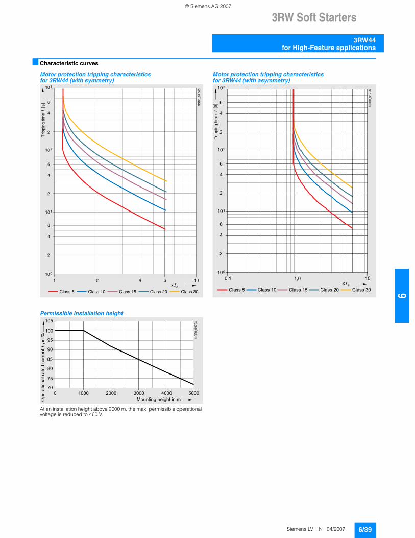
n Characteristic curves
Motor protection tripping characteristics for 3RW44 (with symmetry)
Permissible installation height
At an installation height above 2000 m, the max. permissible operational voltage is reduced to 460 V.
Motor protection tripping characteristics for 3RW44 (with asymmetry)
e
2 4 6 101
Class 10 Class 15 Class 20
10 0
10 1
102
10 3
2
4
6
2
4
6
2
4
6
Class 5 Class 30
NS
B0_
0150
0
[s]
x
Trip
ping
tim
e
85
105
70
75
80
90
95
100
NSB0_
0170
4
0 1000 2000 3000 4000 5000
Operational rated current I
in %
Mounting height in m
e
e
100,1
Class 10 Class 15 Class 20
100
101
102
103
2
4
6
2
4
6
2
4
6
Class 5 Class 30
NSB0_
0170
6
[s]
x1,0
Tripping time
© Siemens AG 2007
3RW Soft Starters
3RW44 for High-Feature applications
6/40 Siemens LV 1 N · 04/2007
6
n More information
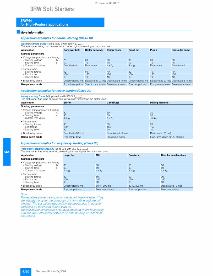
Application examples for normal starting (Class 10)
Application examples for heavy starting (Class 20)
Application examples for very heavy starting (Class 30)
Note:These tables present sample set values and device sizes. They are intended only for the purposes of information and are not binding. The set values depend on the application in question and must be optimized during start-up. The soft starter dimensions should be checked where necessary with the Win-Soft Starter software or with the help of Technical Assistance.
Normal starting Class 10 (up to 20 s with 350 % In motor), The soft starter rating can be selected to be as high as the rating of the motor usedApplication Conveyor belt Roller conveyor Compressor Small fan Pump Hydraulic pump
Starting parameters
• Voltage ramp and current limiting- Starting voltage % 70 60 50 30 30 30- Starting time s 10 10 10 10 10 10- Current limit value Deactivated Deactivated 4 x IM 4 x IM Deactivated Deactivated
• Torque ramp- Starting torque 60 50 40 20 10 10- End torque 150 150 150 150 150 150- Starting time 10 10 10 10 10 10
• Breakaway pulse Deactivated (0 ms) Deactivated (0 ms) Deactivated (0 ms) Deactivated (0 ms) Deactivated (0 ms) Deactivated (0 ms)Ramp-down mode Smooth ramp-down Smooth ramp-down Free ramp-down Free ramp-down Pump ramp-down Free ramp-down
Heavy starting Class 20 (up to 40 s with 350 % In motor), The soft starter has to be selected one rating class higher than the motor usedApplication Stirrer Centrifuge Milling machine
Starting parameters
• Voltage ramp and current limiting- Starting voltage % 30 30 30- Starting time s 30 30 30- Current limit value 4 x IM 4 x IM 4 x IM
• Torque ramp- Starting torque 30 30 30- End torque 150 150 150- Starting time 30 30 30
• Breakaway pulse Deactivated (0 ms) Deactivated (0 ms) Deactivated (0 ms)Ramp-down mode Free ramp-down Free ramp-down Free ramp-down or DC braking
Very heavy starting Class 30 (up to 60 s with 350 % In motor), The soft starter has to be selected two rating classes higher than the motor usedApplication Large fan Mill Breakers Circular saw/bandsaw
Starting parameters
• Voltage ramp and current limiting- Starting voltage % 30 50 50 30- Starting time s 60 60 60 60- Current limit value 4 x IM 4 x IM 4 x IM 4 x IM
• Torque ramp- Starting torque 20 50 50 20- End torque 150 150 150 150- Starting time 60 60 60 60
• Breakaway pulse Deactivated (0 ms) 80 %, 300 ms 80 %, 300 ms Deactivated (0 ms)Ramp-down mode Free ramp-down Free ramp-down Free ramp-down Free ramp-down
© Siemens AG 2007
3RW Soft Starters
3RW44for High-Feature applications
6/41Siemens LV 1 N · 04/2007
66
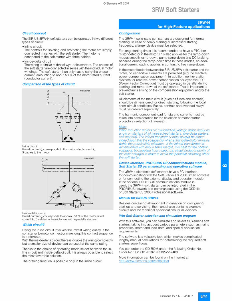
Circuit concept
The SIRIUS 3RW44 soft starters can be operated in two different types of circuit.• Inline circuit
The controls for isolating and protecting the motor are simply connected in series with the soft starter. The motor is connected to the soft starter with three cables.
• Inside-delta circuit The wiring is similar to that of wye-delta starters. The phases of the soft starter are connected in series with the individual motor windings. The soft starter then only has to carry the phase current, amounting to about 58 % of the motor rated current (conductor current).
Comparison of the types of circuit
Inline circuit:Rated current Ie corresponds to the motor rated current In,3 cables to the motor
Inside-delta circuit:Rated current Ie corresponds to approx. 58 % of the motor rated current In, 6 cables to the motor (as with wye-delta starters)
Which circuit?
Using the inline circuit involves the lowest wiring outlay. If the soft starter to motor connections are long, this contact sequence is preferable. With the inside-delta circuit there is double the wiring complexity but a smaller size of device can be used at the same rating.
Thanks to the choice of operating mode select between the in-line circuit and inside-delta circuit, it is always possible to select the most favorable solution.
The braking function is possible only in the inline circuit.
Configuration
The 3RW44 solid-state soft starters are designed for normal starting. In case of heavy starting or increased starting frequency, a larger device must be selected.
For long starting times it is recommended to have a PTC ther-mistor detector in the motor. This also applies for the ramp-down modes smooth ramp-down, pump ramp-down and DC braking, because during the ramp-down time in these modes, an addi-tional current loading applies in contrast to free ramp-down.
In the motor feeder between the SIRIUS 3RW soft starter and the motor, no capacitive elements are permitted (e.g. no reactive-power compensation equipment). In addition, neither static systems for reactive-power compensation nor dynamic PFC (Power Factor Correction) must be operated in parallel during starting and ramp-down of the soft starter. This is important to prevent faults arising on the compensation equipment and/or the soft starter.
All elements of the main circuit (such as fuses and controls) should be dimensioned for direct starting, following the local short-circuit conditions. Fuses, controls and overload relays must be ordered separately.
The harmonic component load for starting currents must be taken into consideration for the selection of motor starter protectors (selection of release).
Note:When induction motors are switched on, voltage drops occur as a rule on starters of all types (direct starters, wye-delta starters, soft starters). The infeed transformer must always be dimen-sioned such that the voltage dip when starting the motor remains within the permissible tolerance. If the infeed transformer is dimensioned with only a small margin, it is best for the control voltage to be supplied from a separate circuit (independently of the main voltage) in order to avoid the potential switching off of the soft starter.
Device interface, PROFIBUS DP communications module, Soft Starter ES parameterizing and operating software
The 3RW44 electronic soft starters have a PC interface for communicating with the Soft Starter ES 2006 Smart software or for connecting the external display and operator module. If the optional PROFIBUS communications module is used, the 3RW44 soft starter can be integrated in the PROFIBUS network and communicate using the GSD fileor Soft Starter ES 2006 Professional software.
Manual for SIRIUS 3RW44
Besides containing all important information on configuring, start-up and servicing, the manual also contains example circuits and the technical specifications for all devices.
Win-Soft Starter selection and simulation program
With this software, you can simulate and select all Siemens soft starters, taking into account various parameters such as mains properties, motor and load data, and special application requirements.
The software is a valuable tool, which makes complicated, lengthy manual calculations for determining the required soft starters superfluous.
You can order the CD-ROM under the following Order No.: Order No.: E20001-D1020-P302-V2-7400.
More information can be found on the Internet at http://www.siemens.com/softstarter
N S B 0 _ 0 0 4 2 4L 1
L 2
L 3
N
P E
N S B 0 _ 0 0 4 2 5L 1
L 2
L 3
N
P E
W 2 W 1 T 3 L 3
V 1
V 2
L 2
T 2
U 2
U 1
T 1
L 1
© Siemens AG 2007
3RW Soft Starters
3RW44 for High-Feature applications
6/42 Siemens LV 1 N · 04/2007
6
SIRIUS soft starter training course (SD-SIRIUSO)
Siemens offers a 2-day training course on the SIRIUS solid-state soft starters to keep customers and own personnel up-to-date on configuring, start-up and maintaining issues.
Please direct enquiries and applications to:
A&D PT 4 (Trainings-Center Erlangen) Werner-von-Siemens-Str. 65 D-91052 Erlangen Telephone: ++49 9131 729262 Telefax: ++49 9131 728172 [email protected] http://www.siemens.com/sitrain
© Siemens AG 2007
3RW Soft Starters
Project planning aids for 3RW44
6/43Siemens LV 1 N · 04/2007
66
n Dimensional drawings
3RW44 2., 3RW44 3. and 3RW44 4. for High-Feature applications
l
e
f
b
p
k io
h
g
m
a
c nd
N S B 0 _ 0 1 4 9 3
q
Type/Dimension (mm)
a b c d e f g h I k l m n o p q
3RW44 2. 180 170 37 11 167 100 240 270 180 148 7.5 153 7 184 6.6 M6, 10 Nm
3RW44 3. 180 170 37 17 167 100 240 270 180 148 7.5 153 7 198 9 M6, 10 Nm
3RW44 4. 210 210 48 25 190 140 269 298 205 166 16 166 9 230 11 M8, 15 Nm
© Siemens AG 2007
3RW Soft Starters
Project planning aids for 3RW44
6/44 Siemens LV 1 N · 04/2007
6
3RW44 5. and 3RW44 6. for High-Feature applications
1) For M12 screw, tightening torque max. 35 Nm (310 lb.in).
3RW49 00-0AC00 external display and operator module 3RW49 00-0AC00 installation cutout for external display and operator module
rs
w
qh
NSB0_01831
ad
tuv
p
no
m
a
ikl
e d
b
1)
c
f g
6T34T22T1
5L33L21L1
Type/Dimension (mm)
a b c d e f g h I k l m
3RW44 5. 76 40 14 20 15.5 638.5 590 -- 44 470 510 16.5
3RW44 6. 85 50 14 -- -- 667 660 160 37.5 535 576 16.5
Type/Dimension (mm)
n o p q r s t u v w ad
3RW44 5. 105 253 623 -- -- -- 249 162 152 -- 290
3RW44 6. 103 251 693 43.5 40 20 249 162 151.4 123 290
SIRIUS 3RW44DEVICE
SF
60
NSB0_
0182
9
96 2829,135,6
NSB0_
0183
0
92
55
© Siemens AG 2007
3RW Soft Starters
Project planning aids for 3RW44
6/45Siemens LV 1 N · 04/2007
66
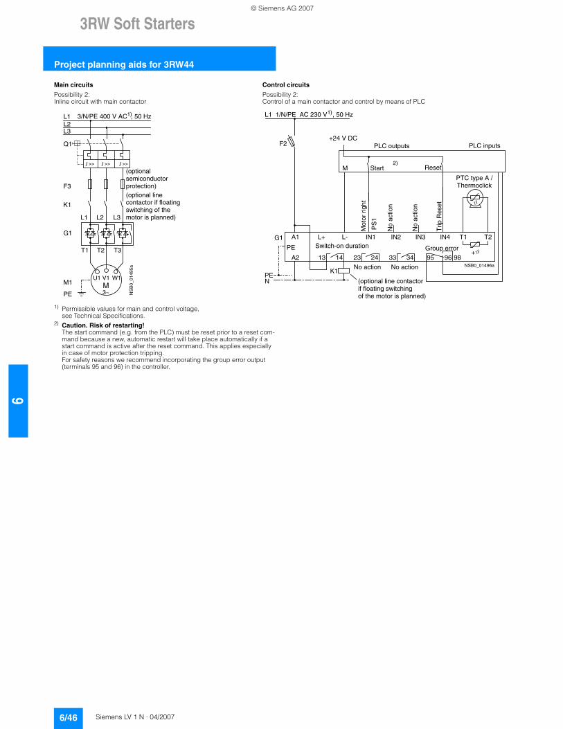
n Schematics
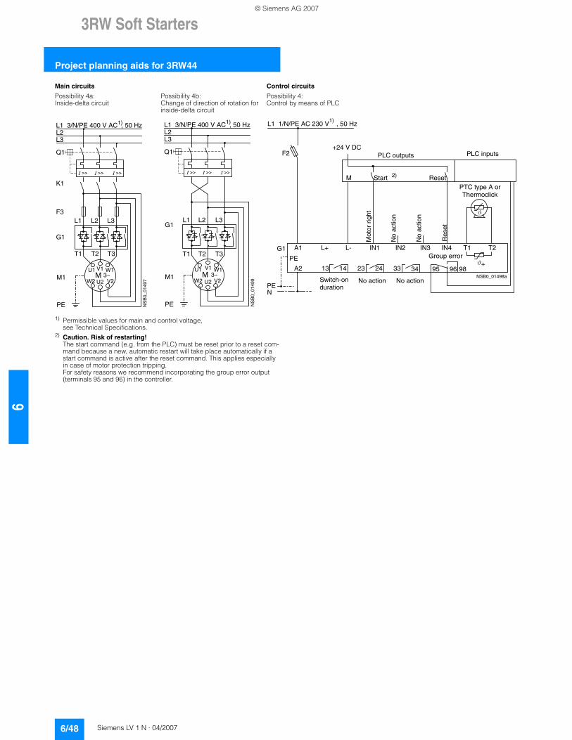
1) Permissible values for main and control voltage, see Technical Specifications.
3RW44 connection examples for main and control circuitsMain circuits Control circuits
Possibility 1a: Possibility 1:Inline circuit with motor starter protector and SITOR fuse (semiconductor protection only)
Control by pushbutton
Main circuits
Possibility 1b: Possibility 1c:Inline circuit with full-range protection (line and semiconductor protection)
Inline circuit with line and SITOR fuse (semiconductor protection only)
Q1
L3L2L1
G1
F3
T1 T2 T3
M1
NS
B0_
0149
0
L1 L2 L3
V1U1 W1M
PE 3~
3/N/PE 400 V AC, 50 Hz
(optional semiconductor protection fuse)
13 14 23 24 33 34 95 9896 +
T1 T2IN4IN3IN2IN1L-L+A1
A2
NPE
PE
G1
F2
NSB0_01494a
Sta
rt S
2
Res
et S
3
StopS1
L1
On periodGrouperror
No
actio
n
No
actio
n
Noaction
PTC type Aor
Thermoclick
Noaction
1/N/PE 230 V AC , 50 Hz
Mot
or o
n rig
htP
S 1
1)
G1
L1 L2 L3
T1 T2 T3
M1
NS
B0_
0149
1
F1'
V1U1 W1M
PE 3~
L3L2L1 1)3/N/PE 400 V AC , 50 Hz
G1
F3
L1 L2 L3
T1 T2 T3
M1
NS
B0_
0149
2
F1
V1U1 W1M
PE 3~
L3L2L1 1)3/N/PE 400 V AC , 50 Hz
© Siemens AG 2007
3RW Soft Starters
Project planning aids for 3RW44
6/46 Siemens LV 1 N · 04/2007
6
1) Permissible values for main and control voltage, see Technical Specifications.
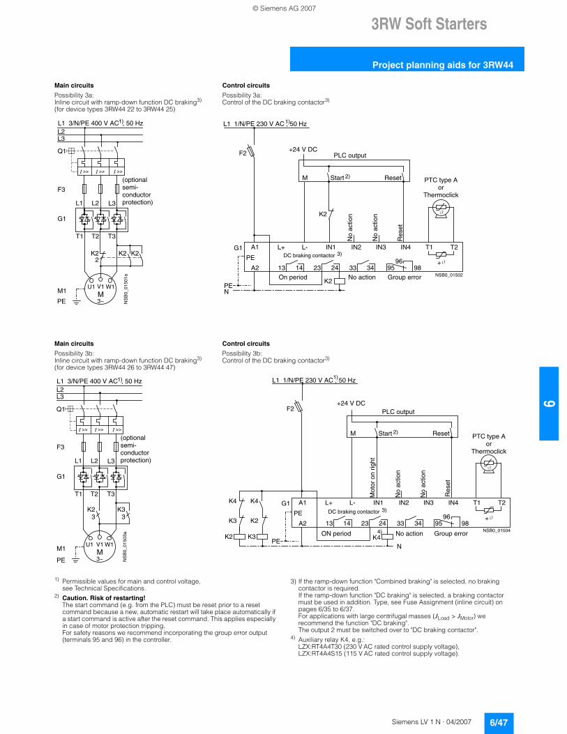
2) Caution. Risk of restarting!The start command (e.g. from the PLC) must be reset prior to a reset com-mand because a new, automatic restart will take place automatically if a start command is active after the reset command. This applies especially in case of motor protection tripping.For safety reasons we recommend incorporating the group error output (terminals 95 and 96) in the controller.
Main circuits Control circuits
Possibility 2: Possibility 2:Inline circuit with main contactor Control of a main contactor and control by means of PLC
Q1
L3L2L1
G1
K1
F3
L1 L2 L3
T1 T2 T3
M1
NS
B0_
0149
5a
V1U1 W1M
PE 3~
1)
(optionalsemiconductorprotection)(optional linecontactor if floatingswitching of the motor is planned)
3/N/PE 400 V AC , 50 Hz
13 14 23 24 33 34 95 9896+
T1 T2IN4IN3IN2IN1L-L+A1
A2
NPE
PE
G1
K1NSB0_01496a
F2+24 V DC
M
L1 1/N/PE AC 230 V , 50 Hz1)
2)
Switch-on duration
Mot
or r
ight
Trip
Res
et
PLC outputs PLC inputs
No
actio
n
No
actio
n
No action No action
Group error
PTC type A /Thermoclick
(optional line contactorif floating switchingof the motor is planned)
PS
1
ResetStart
© Siemens AG 2007
3RW Soft Starters
Project planning aids for 3RW44
6/47Siemens LV 1 N · 04/2007
66
1) Permissible values for main and control voltage, see Technical Specifications.
2) Caution. Risk of restarting!The start command (e.g. from the PLC) must be reset prior to a reset command because a new, automatic restart will take place automatically if a start command is active after the reset command. This applies especially in case of motor protection tripping.For safety reasons we recommend incorporating the group error output (terminals 95 and 96) in the controller.
3) If the ramp-down function "Combined braking" is selected, no braking contactor is required. If the ramp-down function "DC braking" is selected, a braking contactor must be used in addition. Type, see Fuse Assignment (inline circuit) on pages 6/35 to 6/37. For applications with large centrifugal masses (JLoad > JMotor) we recommend the function "DC braking".The output 2 must be switched over to "DC braking contactor".
4) Auxiliary relay K4, e.g.:LZX:RT4A4T30 (230 V AC rated control supply voltage),LZX:RT4A4S15 (115 V AC rated control supply voltage).
Main circuits Control circuits
Possibility 3a: Possibility 3a:Inline circuit with ramp-down function DC braking3)
(for device types 3RW44 22 to 3RW44 25)Control of the DC braking contactor3)
Main circuits Control circuits
Possibility 3b: Possibility 3b:Inline circuit with ramp-down function DC braking3)
(for device types 3RW44 26 to 3RW44 47)Control of the DC braking contactor3)
Q1
L3L2
G1
F3
T1 T2 T3
M1
NS
B0_
0150
1a
L1 L2 L3
V1U1 W1M
K2 K2 K2
PE 3~
1)
2
(optional semi-conductorprotection)
L1 3/N/PE 400 V AC , 50 Hz
13 14 23 24 33 34 95 9896 +
T1 T2IN4IN3IN2IN1L-L+A1
A2
NPE
PE
G1
K2NSB0_01502
Res
et
M Start Reset
+24 V DC
K2
F2
1)
2)
No action Group error
No
actio
n
No
actio
n
On period
PLC output
PTC type Aor
Thermoclick
L1 1/N/PE 230 V AC , 50 Hz
DC braking contactor 3)
K2 K33 3
G1
F3
T1 T2 T3
M1
NS
B0_
0150
3a
L1 L2 L3
V1U1 W1M
PE 3~
Q1
L3L2
1)
(optionalsemi-conductorprotection)
L1 3/N/PE 400 V AC , 50 Hz
13 14 23 24 33 34 95 9896 +
T1 T2IN4IN3IN2IN1L-L+A1
A2
NPE
PE
G1
K4NSB0_01504
Res
et
K4 K4
K3 K2
K2 K3
+24 V DC
M Start Reset
F2
1)
2)
4)
PLC output
No action Group error
No
actio
n
No
actio
n
ON period
PTC type Aor
Thermoclick
Mot
or o
n rig
htL1 1/N/PE 230 V AC , 50 Hz
DC braking contactor 3)
© Siemens AG 2007
3RW Soft Starters
Project planning aids for 3RW44
6/48 Siemens LV 1 N · 04/2007
6
1) Permissible values for main and control voltage, see Technical Specifications.
2) Caution. Risk of restarting!The start command (e.g. from the PLC) must be reset prior to a reset com-mand because a new, automatic restart will take place automatically if a start command is active after the reset command. This applies especially in case of motor protection tripping.For safety reasons we recommend incorporating the group error output (terminals 95 and 96) in the controller.
Main circuits Control circuits
Possibility 4a: Possibility 4b: Possibility 4:Inside-delta circuit Change of direction of rotation for
inside-delta circuitControl by means of PLC
MV1 W1
U2
U1
W2 V2
G1
M1
NS
B0_
0149
7
L1 L2 L3
T1 T2 T3
Q1
F3
K1
PE
3~
L3L2
1)L1 3/N/PE 400 V AC , 50 Hz
G1L1 L2 L3
T1 T2 T3
M1
NS
B0_
0149
9
MV1U1 W1
U2W2 V2
PE
3~
Q1
L3L2
1)L1 3/N/PE 400 V AC , 50 Hz
13 14 23 24 33 34 95 9896+
T1 T2IN4IN3IN2IN1L-L+A1
A2
NPE
PE
G1
NSB0_01498a
+24 V DC
M
F2
L1 1/N/PE AC 230 V , 50 Hz1)
2)
Res
et
Switch-onduration
No action
Group error
No
actio
n
No
actio
n
No action
PTC type A orThermoclick
Mot
or r
ight
PLC outputs PLC inputs
Start Reset
© Siemens AG 2007