air brake system of locomotive
TRANSCRIPT

1
A TRANINNG REPORT ON
AIR BRAKE SYSTEM LOCOMOTIVE WORKSHOP, LUCKNOW
SUBMITTED TO SUBMITTED BY
Mr. KUNAL GUPTA AKASH SINGH
MECH DEPT. B.TECH (ME 4th YEAR)
SESSION-(2014-15)

2
ACKNOLEDGEMENT
I would like to pay my sincere thanks and gratitude to all those who contributed to this vocational training project and help me every time at Northern Railway Locomotive Workshop, Charbagh, Lucknow.
I would like to thanks, Mr S. N. TIWARI (SSE) of the P3PNEMATICsection and Mr. A. K. MANDAL of ELPOH LOCO WORKSHOP/CB/LKO and all staff members for giving their valuable time and guiding me through the entire training period and helping me to come up with this report.
AKASH SINGH B.TECH (MECH.) 3rd YEAR (2013-14) MAHARANA INSTITUTE OF TECHNOLOGY & SCIENCES,
MOHANLALGAN, LUCKNOW

3
CERTIFICATE
This is to be certify that the project title, “AIR BRAKE SYSTEM” is being submitted by AKASH SINGH, has been carried out by his supervision in the degree of B.Tech in Mechanical Engineering.
This is certify that the work is as original one and not been submitted earlier whether to this university or any other institution for the requirement of the course of study.
CHIEF INSTRUCTOR PRINCIPAL
MR. H. I. LAWRENCE

4
CERTIFICATE
5
DECLARATION
I hereby declare that this is summer training project entitle “Air brake system in loco” is an original piece of work done by me for the fulfillment of award of degree bachelor of technology and whatever information has been taken from any source are duly acknowledge.
I therefore declare that this project is carried out for academic progress only.
AKASH SINGH
6
CONTENTS
History of locomotive workshop
Air brake concept Single pipe braking system Twin pipe braking system
Loco brake system
A-9 Automatic brake valve SA-9 Independent brake valve Relay air valve Distributor valve Control valve Emergency valve

7
NORTHERN RAILWAYS
Brief history of Railways workshop:
The Northern Railways Loco Workshop at Charbagh is a good
example of successful adaptation to change and growth.
The railways came to Lucknow on 23rd April 1867 under the
banner of Indian branch Railways Company. This company was
formed in England in 1862 and have begun construction of the
Lucknow – Kanpur railway line as a light mode meter gauge in 1868
crossing Sai River near Harauni and the Nagwa at Lanka.
Later in 1867 the company obtained a contract to build a full scale
broad gauge system in the area north of the gauges and altered its
tittle to the Oudh and Rohailkhand Railways. The O&RR grew to
have three divisions at Allahabad, Lucknow & Moradabad joining up
with the EIR at Kanpur and Ghaziabad.
The railway’s headquarters were at Lucknow. O & RR realized the
need for good maintenance of rolling stock-locus, carriages and

8
manager Mr.T.A.Waide was in position within 18 months of the
opening of the railways to Lucknow in September 1868.
It seems that the workshop started with almost all its work coming
from Britain. The O & RR however was quick to recognize the
advantages of hiring peasants for certain tasks by 1870. The
Charbagh workshop was successful employing native labour. A large
number of people being brought from Bihar. Till 1950 all the
locomotive remaining in India were imported from Britain for every
20 Locomotive imported in the assembled condition one.
Locomotive was imported in knocked down condition to provide
vital spare parts. The first Locomotive of the O & RR come from M/S
Neilson. Periodic overhaul to a Locomotive means that the entire
Locomotive is stripped down. various components cleaned,
inspected, repaired, replaced & assembled again major components
attended to being the boiler, wheels & the engine .Obviously there
was no industry which could manufacture the consumables
required or provide components broken or damaged in accidents .
These items had to be made in the workshop & therefore POH shops

9
had to have basic engineering facilities of blacksmith, foundry &
machines where iron / steel would be cast formed & otherwise
manipulated to produce components for the all-powerful steam
locomotives. Assets of the O&RR along with the shops at Alambagh
&Charbagh were taken over by EIR in 1925. FIR ration aligned their
locomotive POH workload only shunting and small Locomotive.
POH workshop only were sent to Charbagh main line locomotive
being repaired at the EIR’s premier workshop at Jamalpur a district
of Bihar.
During the Second World War as in the first ammunitions of
war produced in the Charbagh workshop practically hand grenades
workshop administrative office itself was used at armory. There was
a small ordinance factory next to the Charbagh shops when the
ordinance work reduced after the war staffs of the factory were
observed in the workshop in 1946 and later the factory itself along
with its land etc. merged with Railways workshop.
Charbagh shops become a part of Northern Railways in1952
regrouping. This Charbagh workshop did not have any Loco POH

10
shops where its Locos could be comfortable based as Mughalpura,
the famous shops of N/W railways had Already gone to Pakistan &
Jamalpur shops were now with Eastern Railways. A major effort was
therefore mounted to develop CB shops increasing its manufacturing
as well as overhauling capabilities from dealing with shunting
Locomotives to that of locomotive working mainline services.
Manufacturing activities continued & reached its peak in the 1960’s
losing way only in the 1970’s. When industries in the country
developed & steam began to be slowly replaced by Diesel
Locomotives, for which components were bought from trade or
specialized components obtained from U.S.A. or the Diesel
Locomotives works Varanasi.
Fortune of the work underwent an ellipse within the importance of
steam traction as Diesel Loco repaired did not demand the same
amount of labour or in-house manufacture of components. Thus ,
while Diesel Loco overhaul was begin at Charbagh in1975 & that of
Electric Locos in1985, there was as extent job , surplus manpower,
loss of relation importance, also lead to reduced investment for
11
machinery, plant & infrastructure. Not with standing these changes,
Charbagh workshops holds a proud distinction of being the only
workshop in Indian Railways overhauling steam, diesel & electric
locos at the same time for a period of 7 years.
In June 1992, the ministry of Railways decided that all steam loco
repair be discontinued & staff employed on such activities,
redeployed in a period of three months.
It is a matter of pride that targets laid down by the ministry were
met. The country’s lost BG steam Locomotive “YUGANTAR” duly
potted was seen off in September 1992. Success in redeployment of
such a large body of staff in a very short period into other lines of
authorities has given the loco works a measure of pride & self-
esteem besides a feeling of belongingness. Staff now clearly
understands that these
Loco works can survive & prosper only by their own hard work,
commitment & good relations. In the year 1993, the rehabilitation of
BOX wagon was started & closed down in the year 1996 .Charbagh
shops were modified to give POH attention to diesel. Electric

12
Locomotive In 1975 from a beginning of one or two locomotive, 10
Locomotive are now given POH/IOH attention per month CB shops
have POHed. Electric Loco have been over hauled till now.
The Charbagh shop is currently blazing a new trail in understanding
work of diverse nature for Indian Railways by emphasis or
innovation cost effectiveness & above all employee involvement. In
this direction the achievement in manufacturing 1500 ballot boxes
for use in Parliamentary Election 1996 within a short time of one
week is a significant step. The POH of DEMU’s consists of
overhauling, repairing & testing of complete electrical & mechanical
control systems & repair of coach including Passenger amenities. CB
loco shop has POHed DEMU coaches till Jan-2005.
Indian railways previously divided into zonal wise in 9 zones. Now a
days it is further extended up to 16 zones mentioned below. Each
zone is headed by General Manager itself who is fully responsible for
operating staff, technical staff and sheds etc.

13
TARGETTED OUT TURN (POH) PER YEAR:
DIESEL LOCO ELECT. LOCO DEMU LOCO
108.0 15.0 50.0
BASIC DATA OF WORKSHOP:
1. Total area 132 x 1000 square meter
2. Total covered area 575 x 1000 square meter
3. Railway line 7.5 Km.
4. Road in shop 4.71 Km.
5. Machine tools installed 720
6. Water storage capacity 5.75 x 1000 liter
7. Consumption average (drinking water) 1.575 x 100000 liter/day
8. Requirement of power/month 272326 KWH
9. Compressed air capacity 7204 CPM

14
ZONAL RAILWAYS:
Indian railways previously divided into zonal wise in 9 zones. Now a days it is further extended up to 16 zones mentioned below. Each zone is headed by General Manager itself who is fully responsible for operating staff, technical staff and sheds etc.
1. Northern Railway
2. Southern Railway
3. Eastern Railway
4. Western Railway
5. Northeast Frontier Railways
6. North Eastern Railway
7. South Eastern Railway
8. South Central Railway
9. Central Railway
10. East Central Railway
11. East Coast
12. North Central

15
13. North Western
14. South Western
15. West Central
16. Bilaspur Zone
This workshop came in the NR zone but the diesel loco, electric loco and DMU coaches that are coming from other zonal railways and these are said to be Foreign Railways.
This Loco Work Shop comes under the category of I.S.O.9000 certified because the quality of the P.O.H. and Technical ability of staff is according to the above standards. This Work Shop is awarded in 2008-2009 for the best P.O.Hed quality of Electric Loco, Diesel Loco and D.M.U. coaches also.
16
BRANCH WISE (TECH) WORK GROUP OF LOCO WORKSHOP:
There are 4 branches according to the different types of work, these are:
1. MECHANICAL BRANCH
2. ELECTRICAL BRANCH
3. ACCOUNTS BRANCH
4. METALLURGICAL BRANCH
5. PERSONAL BRANCH
SUMMARY REPORT:
The summary report related to Diesel/Electric/DMU Coaches covered in a report is named as DSL_HOLD_OUT .This report shows about the locos whether they are coming from NR railways or other than NR railways (which are known as foreign railways).
The outturn, holding, total out-turn during the financial years, last five years out-turn and targeted out-turn for coming years have also been shown in this summary report.

17
Points for POH/IOH/SR:
The points required for calculation of casting for each loco has been shown below:
Repair Category Points
POH 1.0
IOH 0.75
SR 0.25
POH+SR 1.25
IOH+SR 1.0

18
AIR BRAKES
Introduction
The air brake is the standard, fail-safe, train brake used by railways all over the world. In spite of what you might think, there is no mystery to it. It is based on the simple physical properties of compressed air. So here is a simplified description of the air brake system.
Contents
Basics - The Principal Parts of the Air Brake System - Operation on Each Vehicle - Release - Application -Lap - Additional Features of the Air Brake - Emergency Air Brake - Emergency Reservoirs - Distributors -Two-Pipe Systems - Self-Lapping Brake Valves - Other Air Operated Systems - Comment - loco brake.
Basics
A moving train contains energy, known as kinetic energy, which needs to be removed from the train in order to cause it to stop. The simplest way of doing this is to convert the energy into heat. The conversion is usually done by applying a contact material to the rotating wheels or to discs attached to the axles. The material creates friction and converts the kinetic energy into heat. The
19
wheels slow down and eventually the train stops. The material used for braking is normally in the form of a block or pad.
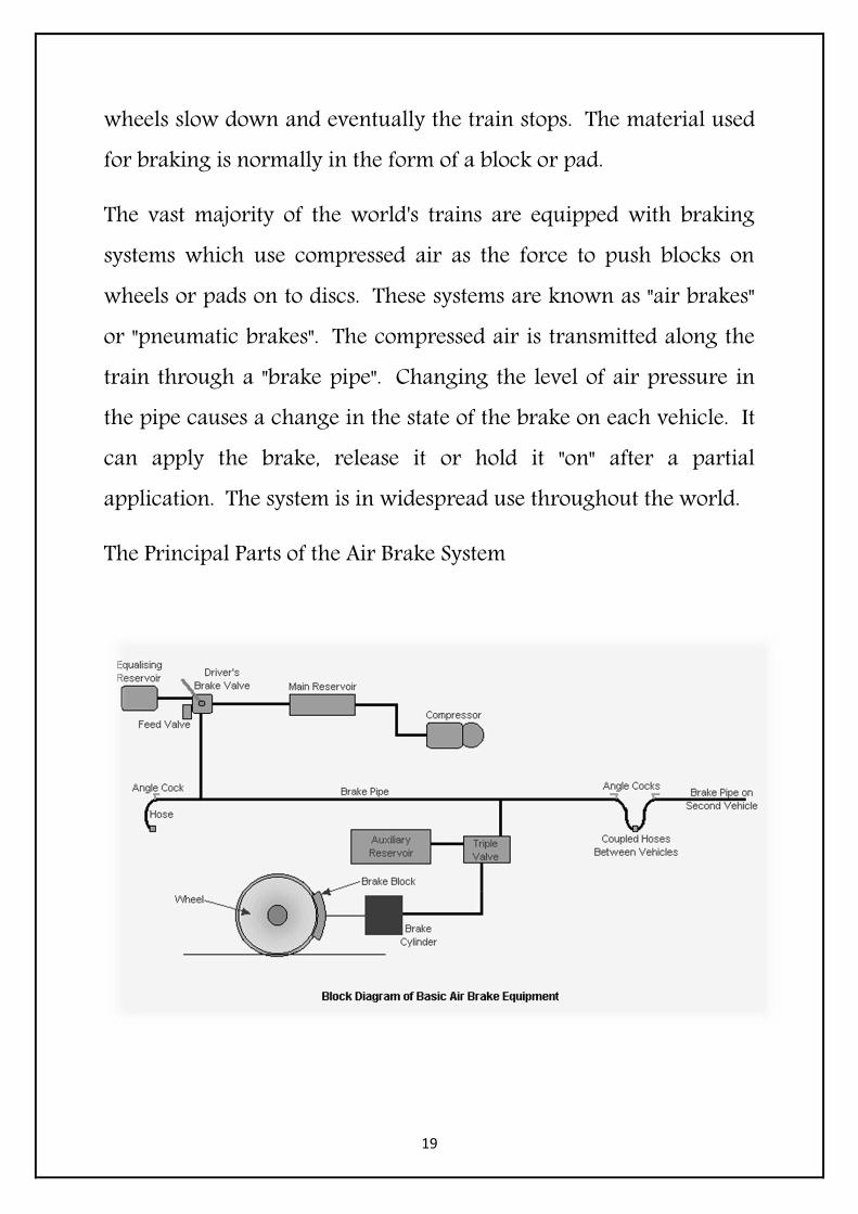
The vast majority of the world's trains are equipped with braking systems which use compressed air as the force to push blocks on wheels or pads on to discs. These systems are known as "air brakes" or "pneumatic brakes". The compressed air is transmitted along the train through a "brake pipe". Changing the level of air pressure in the pipe causes a change in the state of the brake on each vehicle. It can apply the brake, release it or hold it "on" after a partial application. The system is in widespread use throughout the world.
The Principal Parts of the Air Brake System
20
Compressor
The pump which draws air from atmosphere and compresses it for use on the train. Its principal use is for the air brake system, although compressed air has a number of other uses on trains.
Main Reservoir
Storage tank for compressed air for braking and other pneumatic systems.
Driver's Brake Valve
The means by which the driver controls the brake. The brake valve will have (at least) the following positions: "Release", "Running", "Lap" and "Application" and "Emergency". There may also be a "Shut Down" position, which locks the valve out of use.
The "Release" position connects the main reservoir to the brake pipe. This raises the air pressure in the brake pipe as quickly as possible to get a rapid release after the driver gets the signal to start the train.
In the "Running" position, the feed valve is selected. This allows a slow feed to be maintained into the brake pipe to counteract any small leaks or losses in the brake pipe, connections and hoses.
"Lap" is used to shut off the connection between the main reservoir and the brake pipe and to close off the connection to atmosphere after a brake application has been made. It can only be used to provide a partial application. A partial release is not possible with
21
the common forms of air brake, particularly those used on US freight trains.
"Application" closes off the connection from the main reservoir and opens the brake pipe to atmosphere. The brake pipe pressure is reduced as air escapes. The driver (and any observer in the know) can often hear the air escaping.
Most vehicles brake valves were fitted with an "Emergency" position. Its operation is the same as the "Application" position, except that the opening to atmosphere is larger to give a quicker application.
Feed Valve
To ensure that brake pipe pressure remains at the required level, a feed valve is connected between the main reservoir and the brake pipe when the "Running" position is selected. This valve is set to a specific operating pressure. Different railways use different pressures but they generally range between 65 and 90 psi (4.5 to 6.2 bar).
Equalizing Reservoir
This is a small pilot reservoir used to help the driver select the right pressure in the brake pipe when making an application. When an application is made, moving the brake valve handle to the application position does not discharge the brake pipe directly, it lets air out of the equalizing reservoir. The equalizing reservoir is
22
connected to a relay valve (called the "equalizing discharge valve" and not shown in my diagram) which detects the drop in pressure and automatically lets air escape from the brake pipe until the pressure in the pipe is the same as that in the equalizing reservoir.
The equalizing reservoir overcomes the difficulties which can result from a long brake pipe. A long pipe will mean that small changes in pressure selected by the driver to get a low rate of braking will not be seen on his gauge until the change in pressure has stabilized along the whole train. The equalizing reservoir and associated relay valve allows driver to select a brake pipe pressure without having to wait for the actual pressure to settle down along a long brake pipe before he gets an accurate reading.
Brake Pipe
The pipe running the length of the train, which transmits the variations in pressure required to control the brake on each vehicle. It is connected between vehicles by flexible hoses, which can be uncoupled to allow vehicles to be separated. The use of the air system makes the brake "fail safe", i.e. loss of air in the brake pipe will cause the brake to apply. Brake pipe pressure loss can be through a number of causes as follows:
1. A controlled reduction of pressure by the driver 2. A rapid reduction by the driver using the emergency position
on his brake valve

23
3. A rapid reduction by the conductor (guard) who has an emergency valve at his position
4. A rapid reduction by passengers (on some railways) using an emergency system to open a valve
5. A rapid reduction through a burst pipe or hose 6. A rapid reduction when the hoses part as a result of the train
becoming parted or derailed.
Angle Cocks
At the ends of each vehicle, "angle cocks" are provided to allow the ends of the brake pipe hoses to be sealed when the vehicle is uncoupled. The cocks prevent the air being lost from the brake pipe.
Coupled Hoses
The brake pipe is carried between adjacent vehicles through flexible hoses. The hoses can be sealed at the outer ends of the train by closing the angle cocks.
Brake Cylinder
Each vehicle has at least one brake cylinder. Sometimes two or more are provided. The movement of the piston contained inside the cylinder operates the brakes through links called "rigging". The rigging applies the blocks to the wheels. Some modern systems use disc brakes. The piston inside the brake cylinder moves in accordance with the change in air pressure in the cylinder.

24
Auxiliary Reservoir
The operation of the air brake on each vehicle relies on the difference in pressure between one side of the triple valve piston and the other. In order to ensure there is always a source of air available to operate the brake, an "auxiliary reservoir" is connected to one side of the piston by way of the triple valve. The flow of air into and out of the auxiliary reservoir is controlled by the triple valve.
Brake Block
This is the friction material which is pressed against the surface of the wheel tread by the upward movement of the brake cylinder piston. Often made of cast iron or some composition material, brake blocks are the main source of wear in the brake system and require regular inspection to see that they are changed when required.
Many modern braking systems use air operated disc brakes. These operate to the same principles as those used on road vehicles.
Brake Rigging
This is the system by which the movement of the brake cylinder piston transmits pressure to the brake blocks on each wheel. Rigging can often be complex, especially under a passenger car with two blocks to each wheel, making a total of sixteen. Rigging requires careful adjustment to ensure all the blocks operated from one cylinder provide an even rate of application to each wheel. If you

25
change one block, you have to check and adjust all the blocks on that axle.
Triple Valve
The operation of the brake on each vehicle is controlled by the "triple valve", so called because it originally comprised three valves - a "slide valve", incorporating a "graduating valve" and a "regulating valve". It also has functions - to release the brake, to apply it and to hold it at the current level of application. The triple valve contains a slide valve which detects changes in the brake pipe pressure and rearranges the connections inside the valve accordingly. It either:
1. recharges the auxiliary reservoir and opens the brake cylinder exhaust,
2. closes the brake cylinder exhaust and allows the auxiliary reservoir air to feed into the brake cylinder
3. Hold the air pressures in the auxiliary reservoir and brake cylinder at the current level.
The triple valve is now usually replaced by a distributor - a more sophisticated version with built-in refinements like graduated release.

26
OPERATION ON EACH VEHICLE
Brake Release
This diagram shows the condition of the brake cylinder, triple valve and auxiliary reservoir in the brake release position.
The driver has placed the brake valve in the "Release" position. Pressure in the brake pipe is rising and enters the triple valve on each car, pushing the slide valve provided inside the triple valve to the left. The movement of the slide valve allows a "feed groove" above it to open between the brake pipe and the auxiliary reservoir, and another connection below it to open between the brake cylinder and an exhaust port. The feed groove allows brake pipe air pressure to enter the auxiliary reservoir and it will recharge it until its pressure is the same as that in the brake pipe. At the same time, the

27
connection at the bottom of the slide valve will allow any air pressure in the brake cylinder to escape through the exhaust port to atmosphere. As the air escapes, the spring in the cylinder will push the piston back and cause the brake blocks to be removed from contact with the wheels. The train brakes are now released and the auxiliary reservoirs are being replenished ready for another brake application.
Brake Application
This diagram (left) shows the condition of the brake cylinder, triple valve and auxiliary reservoir in the brake application position.
The driver has placed the brake valve in the "Application" position. This causes air pressure in the brake pipe to escape. The loss of pressure is detected by the slide valve in the triple valve. Because the pressure on one side (the brake pipe side) of the valve has fallen, the auxiliary reservoir pressure on the other side has pushed the valve

28
(towards the right) so that the feed groove over the valve is closed. The connection between the brake cylinder and the exhaust underneath the slide valve has also been closed. At the same time a connection between the auxiliary reservoir and the brake cylinder has been opened. Auxiliary reservoir air now feeds through into the brake cylinder. The air pressure forces the piston to move against the spring pressure and causes the brake blocks to be applied to the wheels. Air will continue to pass from the auxiliary reservoir to the brake cylinder until the pressure in both is equal. This is the maximum pressure the brake cylinder will obtain and is equivalent to a full application. To get a full application with a reasonable volume of air, the volume of the brake cylinder is usually about 40% of that of the auxiliary reservoir.
Lap
The purpose of the "Lap" position is to allow the brake rate to be held constant after a partial application has been made.

29
When the driver places the brake valve in the "Lap" position while air is escaping from the brake pipe, the escape is suspended. The brake pipe pressure stops falling. In each triple valve, the suspension of this loss of brake pipe pressure is detected by the slide valve because the auxiliary pressure on the opposite side continues to fall while the brake pipe pressure stops falling. The slide valve therefore moves towards the auxiliary reservoir until the connection to the brake cylinder is closed off. The slide valve is now half-way between its application and release positions and the air pressures are now is a state of balance between the auxiliary reservoir and the brake pipe. The brake cylinder is held constant while the port connection in the triple valve remains closed. The brake is "lapped".
Lap does not work after a release has been initiated. Once the brake valve has been placed in the "Release" position, the slide valves will all be moved to enable the recharge of the auxiliary reservoirs. Another application should not be made until sufficient time has been allowed for this recharge. The length of time will depend on the amount of air used for the previous application and the length of the train.
Additional Features of the Air Brake
What we have seen so far is the basics of the air brake system. Over the 130 years since its invention, there have been a number of improvements as described below.

30
Emergency Air Brake
Most air brake systems have an "Emergency" position on the driver's brake valve. This position dumps the brake pipe air quickly. Although the maximum amount of air which can be obtained in the brake cylinders does not vary on a standard air brake system, the rate of application is faster in "Emergency". Some triple valves are fitted with sensor valves which detect a sudden drop in brake pipe pressure and then locally drop brake pipe pressure. This has the effect of speeding up the drop in pressure along the train - it increases the "propagation rate".
Emergency Reservoirs
Some air brake systems use emergency reservoirs. These are provided on each car like the auxiliary reservoir and are recharged from the brake pipe in a similar way. However, they are only used in an emergency, usually being triggered by the triple valve sensing a sudden drop in brake pipe pressure. A special version of the triple valve (a distributor) is required for cars fitted with emergency reservoirs.
Distributors
A distributor performs the same function as the triple valve, it's just a more sophisticated version. Distributors have the ability to connect an emergency reservoir to the brake system on the vehicle and to

31
recharge it. Distributors may also have a partial release facility, something not usually available with triple valves.
A modern distributor will have:
a quick service feature - where a small chamber inside the distributor is used to accept brake pipe air to assist in the transmission of pressure reduction down the train
a reapplication feature - allowing the brake to be quickly re-applied after a partial release
a graduated release feature - allowing a partial release followed by a holding of the lower application rate
a connection for a variable load valve - allowing brake cylinder pressure to adjust to the weight of the vehicle
chokes (which can be changed) to allow variations in brake application and release times
an in shot feature - to give an initial quick application to get the blocks on the wheels
brake cylinder pressure limiting auxiliary reservoir overcharging prevention.
All of these features are achieved with no electrical control. The control systems comprise diaphragms and springs arranged in a series of complex valves and passages within the steel valve block. Distributors with all these features will normally be provided on passenger trains or specialist high-speed freight vehicles.
32
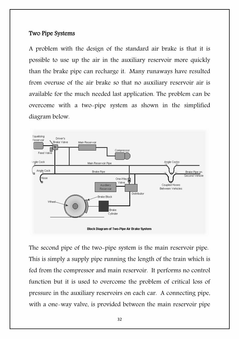
Two Pipe Systems
A problem with the design of the standard air brake is that it is possible to use up the air in the auxiliary reservoir more quickly than the brake pipe can recharge it. Many runaways have resulted from overuse of the air brake so that no auxiliary reservoir air is available for the much needed last application. The problem can be overcome with a two-pipe system as shown in the simplified diagram below.
The second pipe of the two-pipe system is the main reservoir pipe. This is simply a supply pipe running the length of the train which is fed from the compressor and main reservoir. It performs no control function but it is used to overcome the problem of critical loss of pressure in the auxiliary reservoirs on each car. A connecting pipe, with a one-way valve, is provided between the main reservoir pipe

33
and the auxiliary reservoir. The one-way valve allows air from the main reservoir pipe to top up the auxiliary reservoir. The one-way feature of the valve prevents a loss of auxiliary reservoir air if the main reservoir pressure is lost.
Another advantage of the two-pipe system is its ability to provide a quick release. Because the recharging of the auxiliaries is done by the main reservoir pipe, the brake pipe pressure increase which signals a brake release is used just to trigger the brake release on each car, instead of having to supply the auxiliaries as well.
Two pipe systems have distributors in place of triple valves. One feature of the distributor is that it is designed to restrict the brake cylinder pressure so that, while enough air is available to provide a full brake application, there isn't so much that the brake cylinder pressure causes the blocks to lock the wheels and cause a skid. This is an essential feature if the auxiliary reservoir is being topped up with main reservoir air, which is usually kept at a higher pressure than brake pipe air.
Needless to say, fitting a second pipe to every railway vehicle is an expensive business so it is always the aim of the brake equipment designer to allow backward compatibility - in much the same way as new computer programs are usually compatible with older versions. Most vehicles fitted with distributors or two-pipe systems can be

34
operated in trains with simple one-pipe systems and triple valves, subject to the correct set-up during train formation.
Self Lapping Brake Valves
Self lapping is the name given to a brake controller which is position sensitive, i.e. the amount of application depends on the position of the brake valve handle between full release and full application. The closer the brake handle is to full application, the greater the application achieved on the train. The brake valve is fitted with a pressure sensitive valve which allows a reduction in brake pipe pressure according to the position of the brake valve handle selected by the driver. This type of brake control is popular on passenger locomotives.
Other Air Operated Equipment
On an air brake train, the compressed air supply is used to provide power for certain other functions besides braking. These include door operation, whistles/horns, traction equipment, pantograph operation and rail sanders.
Comment
The air brake system is undoubtedly one of the most enduring features of railway technology. It has lasted from its initial introduction in 1869 to the present day and in some places, still hardly different from its Victorian origins. There have been many

35
improvements over the years but the skill required to control any train fitted with pure pneumatic brake control is still only acquired with long hours of practice and care at every stage of the operation. It is often said that whilst it is easy to start a train, it can be very difficult to stop it.

36
LOCO BRAKE SYSTEM
Introduction
Loco brake system is provided to stop the Locomotive, whenever it runs as light engine. It is purely compressed air brake system known as independent brake system. For this separate air circuit is provided in 28LAV-1 & IRAB-1 Brake system which is independent to other air circuit. SA9 Independent brake valve is provided in driving control stand for application & release of loco brake. Valve has three positions i.e. Quick release, release and application.
Purpose of this system
Independent Brake System is designed to apply and release brake on locomotive. When locomotive is moving itself Independent Brake is applied. This system is introduced to run air brake train. Air Brake system can sustain better brake power and can haul a long train. System is designed for Locomotive brake application during train brake application through A9 handle. This is known as synchronising brake system also.
Loco brake valves
SystemconsistsSA9 Independent Brake valve, Double check valve and C2-Relay valve.

37
Description of loco brake system
The SA9 Valve handle is kept normally in release position (right side). MR air is always available at port no.30 of SA9 valve. When handle is brought in application potion (left side) than SA9 port 30 connects port 20 and starts supplying pilot air to C2- Relay air valve. The pilot air passes through MU2B Valve port no. 2&20 and inters to C2-Relay at port no.2. See the line diagram of loco brake system. The pilot air pressure depends upon the handle position, at maximum it is 3.5kg/cm2. The C2-relay air valve actuates after getting pilot air and connects MR pressure to brake cylinders of locomotive through port no.1&3. The brake cylinder pressure depends upon pilot air pressure, supplied into C2-Relay chamber through port no.2. For full brake application SA9 handle is moved to maximum travel position. In this way independent brake/loco brake is applied. There is a gauge line taken from front truck of locomotive to driver’s cabin control stand for indicating brake cylinder pressure. When SA9 handle is placed in release position, loco brakes are released. How MR air is reduced to 3.5kg/cm2 see internal function of the SA9 valve & C2-Relay valve. SA9 Brake valve handle is normally kept in release position. Loco brake can be applied through SA9 Valve handle. It can be applied any desired pressure between the minimum and maximum. This pressure will be automatically maintained in the locomotive brake cylinders against normal leakage from them. The locomotive brake can be graduated on and off with either the
38
automatic (A9) or the independent brake valves (SA9). It is always possible to release the locomotive brakes with the SA9 valve.
Brake Pipe System
Introduction
BP system is introduced to run Air Brake train, where train brake is controlled through BP pipe instead of vacuum pipe. Additional C2-Relay valve is introduced in this system to supply sufficient air to BP system.
BP system valves
BP system consist A9 Automatic brake valve, MU2B valve, Add. /C2-Relay valve, Air flow measuring valve, R-6 Relay air valve and Air flow indicator.
Description of BP system
MR air is connected to A9valve at port 30 and Add. /C2-Relay valve at port 1. Normally A9 handle is kept at release position and maintains 5kg/cm2-air pressure in brake pipe. In this position brakes are found released position. When A9handle is moved to application zone, B P pressure drops through Add. C2-Relay valve, port 3 is connected to exhaust. In this condition brakes are applied. Brake release When A9 handle is moved to release position, Add.

39
C2-Relay valve port3 is connected to port1 and B P pipe is charged to 5kg/ cm2 and brakes are released.
Feed pipe system
Introduction
Air Brake system has two brake pipes, BP pipe and FP pipe.
BP Pipe is provided for brake application and release whereas FP Pipe is provided to help in release time.
FP system valves
System consist Feed valve and Duplex check valve, which are connected from MR-1.
Purpose of the system
Feed Pipe system is introduced to reduce the release time after brake application in air brake trains.
Description of the system
FP System is charged 6kg/cm2 through MR pipe and Feed valve. Air flows from MR-1 to Duplex check valve, which allows air to outlet when MR pressure becomes more than 5kg/cm2. Air reaches directly to feed valve through cut-out cock. Feed valve supply air to feed pipe at 6kg/cm2. How Feed valve reduces the MR pressure to 6kg/cm2 see the internal function of the valve.

40
A-9 Automatic Brake Valve
The A-9 Automatic Brake Valve is a compact self-lapping, pressure maintaining Brake Valve which is capable of graduating the application or release of locomotive and train brakes. A-9 Automatic Brake Valve has five positions: Release, minimum Reduction, Full Service, Over Reduction and Emergency.
Objective
The A9 Automatic Brake Valve maintains 5kg/cm2-air pressure in Brake Pipe System against normal leakage at its release position. It also maintains air pressure drop in the system according to its handle position.
Construction
The A-9 Automatic Brake valve consists of a self-lapping regulating portion, which supplies or exhausts the brake pipe pressure, and a vent valve which is actuated only when the brake valve handle is placed in Emergency position for the purpose of venting brake pipe

41
pressure at an emergency rate. The self-lapping portion is actuated by regulating cam dog 3 on the brake valve handle shaft 32 which controls the supply or exhaust of brake pipe pressure. The vent valve 19 is actuated by special cam dog 23 attached to the brake valve handle which is operative only in Emergency position of the brake valve handle.
The A-9 Automatic Brake Valve is provided an adjusting handle or set screw 15 which serves to permit the proper adjustment of the automatic brake valve to supply brake pipe air to the required operating pressure. There is an inlet valve assembly along with double ball check valve, which moves up and down, when handle moves.
Operation
Charging
The A9 automatic brake valve handle is kept at release position normally. The regulating cam dog 3 holds the inlet and exhaust unit at farthest down ward position. While the regulating valve spring 12 will cause the double ball check assembly 5 to be seated at the exhaust valve and unseated at the inlet valve (see diagrammatic). Main reservoir air is supplied at port No. 30 in the pipe bracket and passes through a strainer to the open inlet valve in to port No.5. This air in port 5 is also ported through a choke passage to the face of regulating valve diaphragm 9. When the pressure on the face of the

42
regulating valve diaphragm 9 overcomes regulating valve spring 12 tension, the regulating valve diaphragm assembly moves down ward and allow the inlet valve spring to seat the double ball check assembly at the inlet valve seat. The A-9 Automatic Valve resumes a lap position.
Application
When the brake valve handle is moved into the minimum reduction, service application zone or full service position, the regulating cam dog 3 on the brake valve handle shaft 32 will permit the inlet valve assembly to move away from the exhaust port by the exhaust valve spring 7. The inlet valve assembly will carry the double ball check assembly with it. This movement will unseat the double ball check valve at exhaust valve seat, thus allowing brake pipe air to flow to exhaust. With the reduction of pressure on regulating valve diaphragm 9, the regulating valve spring 12 will cause a movement of the diaphragm assembly toward the inlet valve and the double ball check valve assembly will be seated at the exhaust valve seat again. The brake valve is to assume a lap position.
Pressure drop in-
Minimum reduction-----.5/.7kg/cm2
Full service-------------1.7/2kg/cm2
Over-reduction---------2.5kg/cm2

43
Release after application
Movement of the brake valve handle toward release position will cause regulating cam 3 to move the inlet valve assembly toward the regulating valve diaphragm assembly. This movement will cause the double ball check valve 5 to be unseated at the inlet valve. Main reservoir air will then flow through the inlet valve to port No. 5. The supply of main reservoir air to the face of regulating valve diaphragm 9 will increase and move down word, resulting in the compression of the regulating valve spring 12. When the force have equalized across the regulating valve diaphragm 9, the double ball check assembly 5 will again seat at the inlet valve due to the force of the inlet valve spring and the brake valve will assume a lap position. Thus it can be seen that the brakes can be graduated off in proportion to the brake valve handle movement from an application position toward release position.
Emergency position
When the brake valve handle is moved to emergency position, the brake valve will perform all the service operations. In the emergency position, the emergency cam dog 23 is actuated through special cam dog 23 to open vent valve 19 and allow brake pipe air to be vented at an emergency rate. Release after an emergency is the same as previously described under release after service.

44
SA-9 Independent Brake Valve
SA-9 Independent Brake Valve is a compact self-lapping, pressure maintaining Brake Valve which is capable of graduating the application or release of Locomotive Air Brakes independent of Automatic Brake. The SA-9 Independent Brake Valve is also capable of releasing an automatic brake application on the Locomotive without affecting the train brake application. The SA-9 Brake Valve has three positions: quick release, release and application.
Objective
The SA9 Independent Brake Valve maintains 3.5kg/cm2-air pressure in the independent brake system against normal leakage through C2-Relay valve. It is supposed to maintain graduated application and release according to its handle position.
Construction
The SA9 Independent Brake Valve consists of a self–lapping regulating portion, which supplies or exhausts air pressure for piloting the graduated application or release of brake cylinder

45
pressure on the locomotive. This brake valve also includes a quick release valve. Both the self-lapping regulating portion and quick release valves of the SA9 Independent Brake valve is actuated by cams attached to the brake valve handle stem. It has regulating valve spring 12, which regulates supply pressure. Exhaust valve spring 7 regulates the movement of exhaust valve. Inlet valve spring keeps inlet ball valve at seat. Quick release valve 17 keeps port no.1&7 separate through its rubber ` o’ rings.
Operation
Charging
In the release position of the brake valve handle, the inlet valve, due to the spring tension of exhaust valve Sparing 7, is positioned at its farthest travel from the regulating valve diaphragm assembly. Which will unseat the double ball check valve at the exhaust valve while being seated at the inlet valve by the inlet valve spring. With the exhaust valve open, there is no air pressure in the independent application port no. 20. Main reservoir air is supplied through port 30 in the pipe bracket and a strainer to the spring chamber of the inlet valve where it is blanked. Vacuum pressure in the vacuum brake pipe is supplied through port No. 1 in the pipe bracket to the spring chamber of the quick release valve where it is blanked. Vacuum reservoir pressure coming from the control valve is

46
supplied through port No. 7 in the pipe bracket and is also blanked to the position of release valve 17.
Application
When the brake valve handle is moved in to the application zone, the regulating cam dog 3 on the brake valve handle shaft 24 forces the inlet valve assembly towards the regulating valve diaphragm assembly and causes the double ball check valve to seat at the exhaust port and open at the inlet valve, thus supplying main reservoir air through the open inlet valve in to the independent application and release pipe (Port 20) which will pilot the locomotive brake application. Main reservoir air is also ported through a choke passage to the face of the regulating valve diaphragm 9. When the pressure on the face of the regulating valve diaphragm 9 overcomes the force exerted by the regulating valve spring 12, the regulating valve diaphragm assembly will move down word. This will allow the inlet valve spring to move the double ball check assembly to the inlet valve seat, thus the brake valve will assume a lap position.
Release after application
When the independent brake valve handle is moved toward release position, the regulating cam dog 3 allows to move the inlet valve assembly up word, carrying the double ball check valve assembly with it, thus unseating the exhaust port while inlet valve remaining

47
seated at the inlet valve seat. A graduated release of brake cylinder pressure will be there, in proportion to the movement of the brake valve handle. At the same time, pressure will be released from top of the diaphragm. When the forces across the regulating valve diaphragm 9 have equalized, the double ball check valve assembly will be seated at both the inlet and exhaust valve seats, and thus the independent brake valve will again assume a lap position.
Quick release position
The quick release position of the independent brake valve provides a means of releasing an automatic brake application on the locomotive without affecting the automatic brake application present on the train brakes. When the independent brake valve handle is placed in the quick release position, the release valve cam 19 positions the release spool valve 17 to connect vacuum control reservoir port 7 to vacuum brake pipe port 1. Since the automatic brake application is in effect on the train, the vacuum pressure in the vacuum control reservoir will be greater than that of vacuum brake pipe, thus the vacuum control reservoir will be Permitted to equalize with the vacuum brake pipe. This will cause the proportionate brake valve to assume a release position and subsequently cause the release of the brake cylinder pressure on the locomotive. The equalizing of the vacuum control reservoir and vacuum brake pipe will have no effect on the VA1–B control valve, thus the vacuum train brakes will remain applied.

48
F-1 Selector Valve
The F-1 Selector Valve performs the function of commanding the brake equipment on the locomotive to lead or trail position of the adjacent locomotive and ensures operation of brakes in the trail locomotives when initiated from the lead locomotive.
C2W Relay Air Valve
The C2W Relay Air Valve is a diaphragm cooperated self-lapping valve having higher capacity which is used as a remote controlled pneumatic device to relay a large quantity of main air reservoir pressure to the operating system for brake application.
49
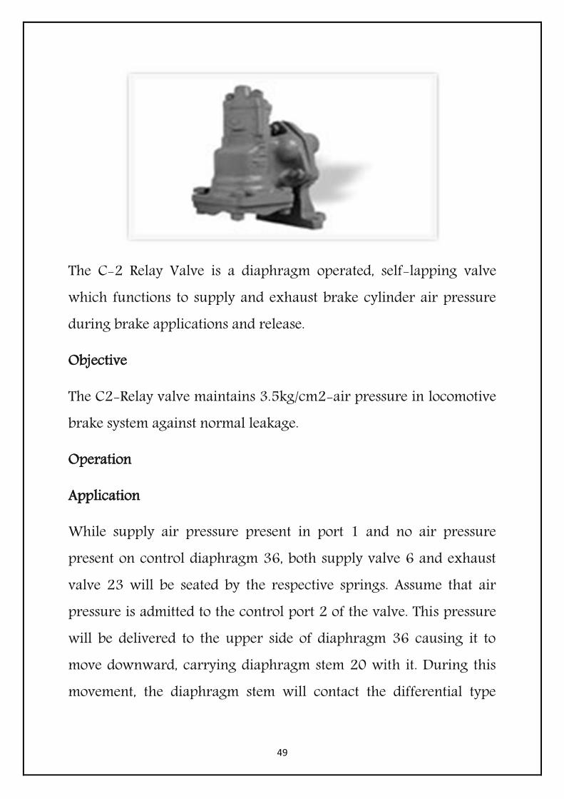
The C-2 Relay Valve is a diaphragm operated, self-lapping valve which functions to supply and exhaust brake cylinder air pressure during brake applications and release.
Objective
The C2-Relay valve maintains 3.5kg/cm2-air pressure in locomotive brake system against normal leakage.
Operation
Application
While supply air pressure present in port 1 and no air pressure present on control diaphragm 36, both supply valve 6 and exhaust valve 23 will be seated by the respective springs. Assume that air pressure is admitted to the control port 2 of the valve. This pressure will be delivered to the upper side of diaphragm 36 causing it to move downward, carrying diaphragm stem 20 with it. During this movement, the diaphragm stem will contact the differential type
50
supply valve 6 and unseat it by compressing supply valve spring 5. Supply air from port 1 will then flow past the unseated valve to the delivery port 3 where it is piped to the brake cylinders. Supply air also flows through a choke in the exhaust valve to the underside of the control diaphragm 36.
When the pressure under the diaphragm is substantially equal to the control pressure on top of the diaphragm, the diaphragm assembly will move back toward its initial position, and supply valve 6 will seal, aided by spring 5 , thus cutting off further flow of supply air to the delivery port.
The relay valve will maintain this delivery pressure against leakage. In the case of a reduction in delivery pressure, the high pressure on the upper side of diaphragm 36 will cause movement downward, repeating the application cycle and restoring the delivery pressure to the desired valve.
Release
When the control pressure to the valve is reduced, the high pressure on the underside of diaphragm 36 will cause it to move upward, carrying stem 20 with it. During this movement, the shoulder on the diaphragm stem will contact differential type exhaust valve 23 and unseat it by compression of spring 27. Air from the delivery port will then flow past unseated exhaust valve 23 to atmosphere, reducing the pressure in the brake cylinders. When the pressure has been
51
reduced to balance the pressure in the diaphragm, the diaphragm assembly will move back to its initial position and exhaust valve 23 will seal, aided by spring 27, thus cutting off the flow of brake cylinder air to exhaust. If the control pressure is completely removed from diaphragm 36, the valve will completely exhaust the delivery pressure to the brake cylinders.
MU-2B valve
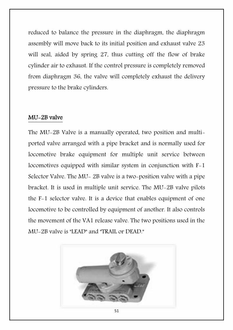
The MU-2B Valve is a manually operated, two position and multi-ported valve arranged with a pipe bracket and is normally used for locomotive brake equipment for multiple unit service between locomotives equipped with similar system in conjunction with F-1 Selector Valve. The MU- 2B valve is a two-position valve with a pipe bracket. It is used in multiple unit service. The MU-2B valve pilots the F-1 selector valve. It is a device that enables equipment of one locomotive to be controlled by equipment of another. It also controls the movement of the VA1 release valve. The two positions used in the MU-2B valve is "LEAD" and "TRAIL or DEAD."
52
Objective
This valve is provided to work in multiunit operation. In trail unit brake application valves are isolated through this valve.
Construction
MU2B Valve has two positions, which works as a spool valve. It has number of port connections.
Operation
In "LEAD" position, main reservoir air piped to port 63 is connected to port 53 and thus to the double check valve that leads to the piston of the VA–1 release valve.
Independent brake control pressure is connected to port 2 &20 of the MU– 2B valve. Port 13 and port 3 are connected as a means of providing the passage to charge the brake pipe from the automatic brake valve. Port 30 connected to the F1 selector valve provides the connection for a supply of MR air that positions the F1 selector valve when the locomotive is used as a trailing unit.
When the unit is used as a trail locomotive, the MU-2B valve is positioned in "TRAIL or DEAD" position. Ports 2, 3, and 20 are blanked at the MU-2B valve. Port 53 is connected to exhaust at the MU- 2B valve. Main reservoir piped to port 63 is connected to port 30, which in turn, positions the F-1 selector valve of trail position operation. At the F- 1 selector valve, brake cylinder equalizing pipe

53
air, port 14, is connected to ports 16 and 20, both of which are connected through a double check valve and thus to the control port of the relay valve. This provides a passage for air emanating from the lead unit during a brake application.
C3W Distributor Valve
C3W Distributor Valve is a graduated release UIC approved Distributor Valve for application in the Coach Brake System used for initiating the brake application. These valves are supplied in Aluminium version as well as Cast Iron version as far as Body, Top covers and Bottom Covers are concerned.

54
VA-1B Control Valve
The VA-1B Control Valve proportions the amount of vacuum in the vacuum brake pipe to the air pressure in the compressed air brake pipe on the locomotive and acts as a pilot valve to operate the train vacuum brake, thus securing an application simultaneously with, and in proportion to the locomotive air brake application.
Objective
VA1B control valve is deployed in vacuum brake system to apply and release the train brake.
Construction
The control valve has three portions. Top cover, valve body and bottom cover with protection valve. The valve body contains sleeve, control valve 6, contacted on its upper side through its upper pusher pin 7 to small diaphragm 8 through diaphragm follower 9. It is also contacted on its bottom side through lower pusher pin 19 to large

55
diaphragm 21 through diaphragm follower 22. The VA1B Control valve has six pipe connections (see piping diagram).
3 – Brake Pipe pressure
6 – Vacuum train pipe
2 --Vacuum train pipe
1 – Vacuum Control pipe
7 – Vacuum Reservoir Pipe to exhauster
8 – Atmosphere through GD-80 filter
Top diaphragm makes two chambers, chamber A is connected to B P pressure 5kg/cm2 through port 3 and chamber B is connected to atmosphere through a breather port. Bottom diaphragm makes two chambers, chamber C is connected to vacuum train pipe through port2 and chamber D is connected to vacuum control pressure 1.7kg/cm2 through port1.
Operation
The VA1B control valve is actuated through A9 valve. The deferent positions of A9 is described below.
Release
When 5kg/cm2 pressure is available in chamber A, 56cm vacuum in chamber C, and 1.7kg/cm2 pressure in chamber D, the valve remains in balanced or lapped position and all the ports are closed.

56
Suppose there has been a brake application, in chamber a pressure will drop and in chamber C vacuum will drop. When the A9 valve handle is moved in release position the brake pipe pressure starts increasing, the pressure in chamber A also increases, the control valve moves down connecting port 7 to port 6. In this way the exhauster starts creating vacuum in the train pipe. As the vacuum is restored in the vacuum train pipe and in chamber C of the control valve, the 1.7kg/cm2 pressure supplied to chamber D moves the diaphragm 20 and valve 6 upward.
When the vacuum in chamber C is increased to approximately 56cm the upward movement of the valve 6 will lap itself leaving only enough opening to permit the exhauster to maintain vacuum against leakage in the train pipe.
Application
When the vacuum is restored in the vacuum brake system and it is desired to apply the brakes, the brake valve handle is moved to application position, causing a reduction in brake pipe pressure. As chamber A of the VA1B Control Valve is connected to the brake pipe, a reduction in pressure in this chamber also takes place. The 1.7kg/cm2 pressure in chamber D then moves the diaphragm follower and control valve upward as the brake pipe pressure is reduced. The control valve connects pipe 6 and chamber C to atmospheric port 8. Thus, atmospheric air pressure enters the

57
vacuum train pipe. Thereby the vacuum brakes are applied on train. The pipe connection no. 2 between chamber C and pipe 6 allows drop in vacuum in chamber C through a choke also and the valve comes to lap position. The constant braking force is maintained against normal leakage. It is understood that two pressure i.e. brake pipe and vacuum are varying and for different combination of these two forces the valve gets lapped position giving different braking forces.
D-1 Emergency Brake Valve
The D-1 Emergency Brake Valve is a manually operated device which provides a means of initiating an emergency brake application.
When it is desired to make the shortest possible stop, the brake valve handle is moved to Emergency position, causing an emergency rate of brake pipe reduction. The HS4 control air valve also contains provision for reducing any excess pressure in the delivery pipe, as

58
when the pressure called for by the setting of adjusting handle 15 is lowered. Excess pressure in the chamber above diaphragm 11 moves the diaphragm and exhaust valve seat 10 downward away from exhaust valve 5b, The excess air pressure then flows past the unseated exhaust valve 5b, through the exhaust valve spring chamber and the diaphragm spring chamber and out to atmosphere through the opening in the bottom cover.
J-1 Safety Valve
The J-1 Safety Valve installed vertically in the main reservoir system vents pressure at a predetermined setting to atmosphere in order to prevent excessive main reservoir pressure build up.

59
D-1 Automatic Drain Valve
The D-1 Automatic Drain Valve automatically discharges precipitated moisture from reservoir with each operating cycle of the control device. The drain valve may be installed on main reservoir with a sump.

60
D-24 B Feed Valve
The D-24 B Feed Valve is a large capacity highly sensitive relay valve which is designed to direct the flow of air under pressure to various devices in air brake equipment arrangement at a predetermined pressure.
61
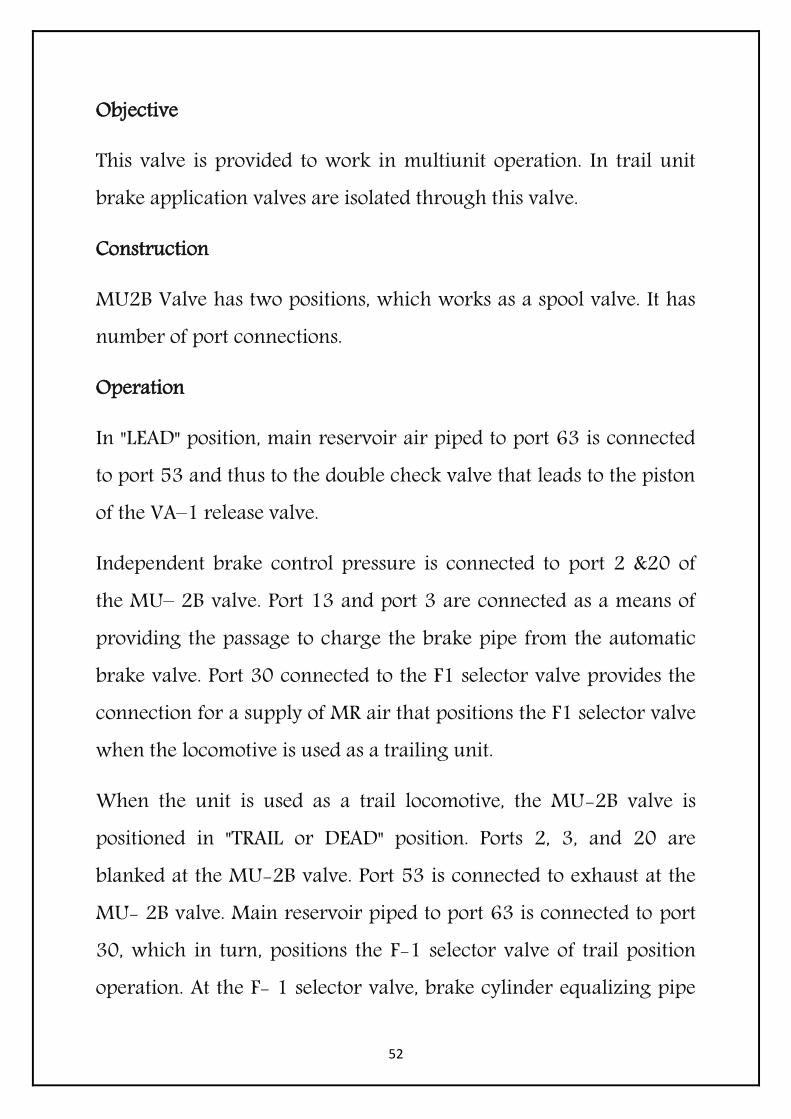
N-1 Reducing Valve
The N-1 Reducing Valve reduces the pressure of compressed air supply to a constant predetermined value and delivers the same usually for operation of auxiliary devices.

62
24-A Double Check valve
The 24-A Double Check Valve is used to permit a device to be controlled by either of two other devices. Double check valve is used to provide control of two sources without interaction between the two.
Objective
The double check valve has two receiving ends that is why this valve is used at several points in air brake system, wherever two air sources are possible.
Construction
There is an internal floating check valve with "O" ring seal 7, automatically directs the flow of air from one or the other of the two controlling devices to a common discharge. At the same time, prevents this air from flowing to the inoperative controlling device.

63
Operation
Referring to the assembly view, when a pressure differential exists between the two end ports, the higher air pressure forces the check valve 4 over to seal against its seat 3 on the flow pressure side. This closes the passage between the low-pressure port and the common port in the body 2. Air then flows from the high-pressure port through the common port to the control device.
Important feature of the brake system
1. Locomotive brakes may be applied with any desired pressure between the minimum and maximum. This pressure will be maintained automatically in the locomotive brake cylinders against normal leakage from them.
2. The locomotive brakes can be graduated on & off with either the automatic or the independent brake valve.
3. It is always possible to release the locomotive brakes with the independent brake valve, even when automatically applied.
4. The maximum braking position emergency, ensuring the shortest possible stops distance.
5. It is always possible to haul both vacuum / air brake trains.
6. Automatic brake application and power cut off with idle rpm of engine is always possible during train parting.

64
7. Multiple unit operation is also possible.
Releasing of brake
When handle is moved to release position, A9 valve starts supplying full control pressure to add. C2 Relay valve causing BP pressure start increasing to 5kg/cm2 and brakes are released.
Application of brake
A9 handle is moved in application zone for brake application. A9 reduces Control pressure to Add.C2 Relay valve. Add. C2 Relay reduces BP pressure in proportion to control pressure drop. BP pressure may be zero if A9handle moved at over reduction position. If handle is placed at emergency position BP will drop to zero immediately within 3 sec. After dropping BP pressure brakes are applied.

65
THANK YOU!