airborne systems health monitoring - aig.si · airborne systems health monitoring ... consisting of...
TRANSCRIPT

Airborne systems health monitoring
Tine Tomažič, Gregor Veble, Vid Plevnik, Jure Tomažič, Drago Matko PIPISTREL d.o.o., Ajdovščina, Goriška cesta 50a, SI-5270 Ajdovščina, Slovenia (tine.tomazic, gregor.veble, vid.plevnik, jure.tomazic, drago.matko)@pipistrel.si
Abstract
In the contribution an overview of aircraft avionic systems is given, starting from basic six pack navigation instruments, followed by advanced electronic avionic systems and ending with recent developments in hybrid propulsion systems monitoring. Special attention is given to avionics of all generations of Pipistrel aircraft. While the basic mechanical six pack navigation instrument set was installed in early Sinus and Virus planes, Alpha trainer is a full-featured, fully equipped airplane with cockpit instruments in classical look but modern electronic realization. In the new generations of Pipistrel aircraft, such as Virus SW and Panthera, up to date avionics can be installed according to the customer wishes as demonstrated in the contribution. Finally the health monitoring of new propulsion types (electro, hybrid) is presented.
Nadzor delovanja sistemov za let
V prispevku je podan pregled avionike letal in sicer od klasičnega nabora šestih inštrumentov za navigacijo preko naprednih elektronskih sistemov do najnovejših sistemov za nadzor hibridnih pogonov. Poseben poudarek je dan avioniki letal vseh generacij tovarne Pipistrel. Medtem ko so bili prvi Sinusi in Virusi opremljeni s klasičnim naborom šestih navigacijskih inštrumentov, je Alpha trainer popolnoma opremljeno letalo z elektronsko izvedenimi inštrumenti klasičnega izgleda. Novejše generacije Pipistrelovih letal, kot sta Virus SW in Panthera, je možno, glede na želje kupcev, opremiti s sodobno avioniko, kot je to pokazano v prispevku. Prispevek zaključuje predstavitev sistemov nadzora novejših tipov pogona, kot sta električni in hibridni pogon.

1 Introduction
Airborne systems health monitoring the most important job of all pilots. They have today an unprecedented amount of information available at their fingertips. Electronic flight instruments use innovative techniques to determine aircraft attitude, speed, and altitude, presenting a wealth of information in one or more integrated presentations. A suite of cockpit information systems provides pilots with data about aircraft position, planned route, engine health and performance, as well as surrounding weather, traffic, and terrain.
In this contribution an overview of aircraft avionics is given with special emphasis on all generations of Pipistrel aircraft. In Section 2 the classic aircraft avionics is given together with its implementations on early generation of Pipistrel aircraft. In Section 3 advanced avionics is reviewed and its implementation on recent generation of Pipistrel aircraft is given. Propulsion system monitoring with emphasis on electric and recent development in hybrid propulsion is presented in Section 4.
2 Classic aircraft avionics
Aircraft avionic systems include basic flight instruments, communication systems, naviga-tion facilities, Engine Monitoring System (EMS), system status and control items (landing gear control, flaps, lights etc), information systems and automated flight control.
Basic flight instruments are the instruments in the cockpit of an aircraft that provide the pilot with information about the flight situation of that aircraft, such as altitude, speed and direction.
Engine Monitoring System (EMS), basically consisting of RPM and oil temperature gauges.
Communication (COM) systems connect the flight deck to the ground and other aircrafts.
Navigation is the determination of position and direction on or above the surface of the
Earth. Avionics can use satellite-based systems (such as GPS and WAAS), ground-based systems (such as VOR or LORAN), or any combination thereof. Navigation systems calculate the position automatically and display it to the flight crew on moving map displays. Older avionics required a pilot or navigator to plot the intersection of signals on a paper map to determine an aircraft's location; modern systems calculate the position automatically and display it to the flight crew on moving map displays.
Information systems support the pilot in following flight progress, and in avoiding terrain, traffic, and weather hazards en route. A moving map continuously displays the aircraft’s position relative to the intended route of flight, and helps the pilot to maintain the “big picture” (situational awareness) as his flight progresses. A Terrain Awareness and Warning System (TAWS) color codes surrounding terrain to make it easily apparent when terrain poses a threat. Weather systems provide in-flight access to many of the same weather products available on the ground. A fuel management system makes predictions about fuel remaining at each waypoint along the route, and helps monitor actual fuel use as the flight progresses.
Automated flight control system can significantly reduce workload during critical phases of flight. The two-axis autopilot system installed in most general aviation aircraft controls the pitch and roll of the aircraft. The autopilot can operate independently, controlling heading and altitude, or it can be coupled to a navigation system and fly a programmed course or an approach with glideslope.
2.1 Basic flight instruments
Basic flight instruments are of particular use in conditions of poor visibility, such as in clouds, when such information is not available from visual reference outside the aircraft. The term is sometimes used loosely as a synonym for cockpit instruments as a whole, in which context it can include engine instruments, navigational and communication equipment [1].
The altimeter shows the aircraft's altitude above sea-level by measuring the difference between the pressure in a stack of aneroid capsules inside the altimeter and the atmospheric pressure obtained through the static system. It is adjustable for local barometric pressure which must be set correctly to obtain accurate altitude readings.
The attitude indicator (also known as an artificial horizon) shows the aircraft's relation to the horizon. From this the pilot can tell whether the wings are level and if the aircraft nose is pointing above or below the horizon.
The airspeed indicator shows the aircraft's speed relative to the surrounding air. It works by measuring the ram-air pressure in the aircraft's Pitot tube. The indicated airspeed must be corrected for air density (which varies with altitude, temperature and humidity) in order to obtain the true airspeed, and for wind conditions in order to obtain the speed over the ground.
The compass shows the aircraft's heading relative to magnetic north. While reliable in steady level flight it can give confusing indications when turning, climbing, descending, or accelerating due to the inclination of the Earth's magnetic field. For this reason, the heading indicator is also used for aircraft operation.
The heading indicator (also known as the directional gyro, or DG; sometimes also called the gyrocompass, though usually not in aviation applications) displays the aircraft's heading with respect to magnetic north. Principle of operation is a spinning gyroscope, and is therefore subject to drift errors (called precession) which must be periodically corrected by calibrating the instrument to the magnetic compass. In many advanced aircraft avionic, the heading indicator is replaced by a horizontal situation indicator (HSI) which provides the same heading information, but also assists with navigation.
The vertical speed indicator (also sometimes called a variometer, or rate of climb indicator) senses changing air pressure, and displays that information to the pilot as a rate of climb or descent.
The turn/bank indicator indicates whether the aircraft is in coordinated flight, i.e. it is flying with zero sideslip. It usually shows the ball in the centre of the spirit level. The occupants perceive no lateral acceleration of the aircraft and their weight to be acting straight downwards into their seats.
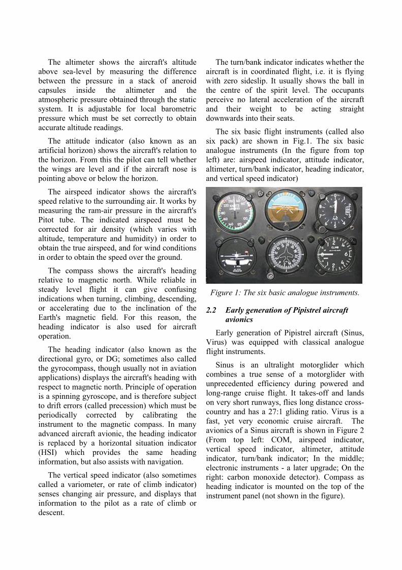
The six basic flight instruments (called also six pack) are shown in Fig.1. The six basic analogue instruments (In the figure from top left) are: airspeed indicator, attitude indicator, altimeter, turn/bank indicator, heading indicator, and vertical speed indicator)
Figure 1: The six basic analogue instruments.
2.2 Early generation of Pipistrel aircraft avionics
Early generation of Pipistrel aircraft (Sinus, Virus) was equipped with classical analogue flight instruments.
Sinus is an ultralight motorglider which combines a true sense of a motorglider with unprecedented efficiency during powered and long-range cruise flight. It takes-off and lands on very short runways, flies long distance cross-country and has a 27:1 gliding ratio. Virus is a fast, yet very economic cruise aircraft. The avionics of a Sinus aircraft is shown in Figure 2 (From top left: COM, airspeed indicator, vertical speed indicator, altimeter, attitude indicator, turn/bank indicator; In the middle; electronic instruments - a later upgrade; On the right: carbon monoxide detector). Compass as heading indicator is mounted on the top of the instrument panel (not shown in the figure).

Figure 2: Avionics of Pipistrel Sinus aircraft.
2.3 Electronic avionics
The arrival of new technology to general aviation aircraft has generated noticeable changes in three areas: information, automation, and options. Electronic flight instruments use innovative techniques to determine aircraft attitude, speed, and altitude, presenting a wealth of information in one or more integrated presentations. A suite of cockpit information systems provides pilots with data about aircraft position, planned route, engine health and performance, as well as surrounding weather, traffic, and terrain.
Since all flight instruments may be combined in one integrated electronic flight instrument system, a number of enhancements to conventional flight instruments are now possible.
The attitude of the aircraft may be measured using microelectronic sensors that are more sensitive and reliable than traditional gyroscopic instruments. These sensors measure pitch, roll, and yaw movements away from a known reference attitude. Aircraft heading may be determined using a magnetic direction-sensing device such as a magnetometer or a magnetic flux valve.
Attitude and heading systems are typically bundled together as an attitude heading reference system (AHRS), which contains not only the sensors used to measure attitude and heading, but also a computer that accepts sensor inputs and performs calculations. Some AHRSs must be initialized on the ground prior to departure. The initialization procedure allows
the system to establish a reference attitude used as a benchmark for all future attitude changes. As in any navigation system, attitude heading reference systems accumulate error over time. For this reason, AHRSs continually correct themselves, using periods of stable flight to make small corrections to the reference attitude. The mathematical background of this procedure is the Kalman filter. The system’s ability to correct itself can be diminished during prolonged periods of turbulence. Some AHRSs can be reinitialized in flight, while others cannot. The pilot must become familiar with the operating procedures and capabilities of a particular system.
Information on altitude and airspeed is provided by sensors that measure static and ram air pressure. An air data computer (ADC) combines those air pressure and temperature sensors with a computer processor that is capable of calculating pressure altitude, indicated airspeed, vertical speed, and true airspeed. An air data attitude heading reference system (ADAHRS) combines all of the systems previously described into one integrated unit.
2.4 Alpha trainer
Pipistrel Alpha trainer is a full-featured, fully equipped aeroplane, ready to operate on the flight line. Its cockpit instruments design is based on a quarter of century of aircraft building experience. We have learned that a training aircraft must have a classic-looking instrument panel, so this look is kept, but modernised with electronic instruments for better visibility and reliability using large and very easy to read 3 1/8” (80 mm) airspeed indicator and altimeter [3].
Conventional-looking aircraft instruments are all clearly labelled with the correct colour coded speeds and temperatures in a traditional and familiar training format.
Variometer and engine RPM counter have two separate displays while the other engine parameters are displayed in a common multifunction very bright full-colour display

with audio alarms for exceeded values, which significantly increases the safety.
All avionics are well-lit with their own light source which enables good visibility during all kinds of light conditions; equally visible during both day and night flying. Flight avionics of Alpha trainer is shown in Figure 3 (From top left: airspeed indicator, attitude indicator, altimeter; RPM indicator, EMS display, navigation display, vertical speed indicator; COM). Compass as heading indicator is mounted on the top of the instrument panel - not shown in the figure).
Figure 3: Avionics of Pipistrel Alpha trainer.
3 Advanced aircraft avionics
The primary flight instruments can all be displayed simultaneously on one reasonably easy-to-read video monitor much like the flat panel displays in laptop computers. These displays are called primary flight displays (PFDs).
A PFD presents information about primary flight instruments, navigation instruments, and the status of the flight in one integrated display. Some systems include EMS information and other systems information in the same display. The pilot must still cross-check around the panel and on the display, but more information is available in a smaller space in easier to read colours. The primary flight instruments that appear on a PFD are driven by instrument sensor systems that are more sophisticated than conventional instrument systems. A typical PFD (Kanardia Nesis) [4] is shown in Figure 4.
Figure 4: Kanardia Nesis as primary flight display.
Flight instrument presentations on a PFD differ from conventional instrumentation not only in format, but sometimes in location as well. For example, the attitude indicator on the PFD in Figure 4 is larger than conventional round-dial presentations of an artificial horizon. Airspeed and altitude indications are presented on vertical tape displays that appear on the left and right sides of the primary flight display. The vertical speed indicator is depicted using conventional analogue presentation. Turn coordination is shown using a segmented triangle near the top of the attitude indicator. Pilots need to train their eyes to find and interpret these instruments in their new formats and locations. A terrain relief may be included into the attitude indicator, as shown in Fig.4.
However due to the flexibility of today’s information technology, several views can be presented in the PFD, as shown in Figure 5, illustrating several views of the Kanardia Nesis [4], among them also the classic view that mimics a classical look of the instruments with modern enhancements.
This kind of displays is called Multi-function displays (MFD). MFDs may provide the same type of display as installed in the PFD position, but are usually programmed to display just the navigation information with traffic, systems data, radar Stormscope®/ Strikefinder® [2]. They enable pilots to fly under Instrumental Flight Rules (IFR).

Figure 5: Several views of the Kanardia Nesis.
However, in many systems, the MFD can be selected to repeat the information presented on the PFD, thereby becoming the standby PFD. The pilot should be absolutely certain of and proficient with the standby modes of operation.
PFDs have evolved and have become more than flight displays in many cases. The amount of data available for display can overwhelm the pilot with data. Therefore, many manufacturers have integrated data control and display controls into the display unit itself, usually around the perimeter of the unit. These data and display controls provide different ways of selecting necessary information, such as altimeter settings, radials, and courses. Figure 6 illustrates two different kinds of controls for making entries on primary flight displays. Some PFDs utilize a single knob and button-selectable windows to determine which entry is to be made. Other PFDs offer dedicated knobs for making entries; quantities are sometimes entered in one location and displayed in another. Still other units retain all controls on a separate control panel in the console or on the instrument panel.
Figure 6: Dynon Skyview [5].
The modern information/navigation/commu-nication technology enables numerous pos-sibilities to increase flight safety and pilot comfort. Only a few will be mentioned here.
The flight director directs the pilot to follow the prescribed path (required pitch and bank angles) by matching the yellow and violet bars, as depicted in Figure 7. The prescribed path can be either a set of waypoints or an instrument landing system radio beam.
Figure 7: Garmin G3X flight director [6].
FLARM [7] (the name being inspired from 'flight alarm') is an electronic device to selectively alert pilots to potential collisions between aircraft. The position of the aircraft is obtained from an internal GPS and a barometric sensor and then broadcasted with forecast data about the future 3d flight track. Its receiver listens for other FLARM devices within typically 3-5 kilometres and processes the information received. Motion-prediction algorithms predict potential conflicts for up to 50 other signals and warn the pilot using sound and visual means. FLARM can also store information about static aerial obstacles, such as cables, in a database. Unlike conventional transponders in aircraft, FLARM has a low power consumption and is relatively cheap to buy and to install. Furthermore, conventional Airborne Collision Avoidance Systems (ACAS) are of little use in preventing gliders from colliding with each other because gliders are frequently close to each other without being in danger of collision. ACAS would give out

continuous and unnecessary warnings about all aircraft in the vicinity, whereas FLARM only gives selective alerts to aircraft posing a collision risk. Versions are sold for use in light aircraft and helicopters, as well as gliders. However the short range of the signal makes FLARM unsuitable for avoiding collisions with fast moving aircraft such as commercial and military jets.
Automatic dependent surveillance – broad-cast (ADS–B) [8] is a cooperative surveillance technology in which an aircraft determines its position via satellite navigation and periodically broadcasts it, enabling it to be tracked. The information can be received by air traffic control ground stations as a replacement for secondary radar (transponder). It can also be received by other aircraft to provide situational awareness and allow self- separation. The ADS-B system can also provide traffic and government generated graphical weather information through TIS-B and FIS-B applications. ADS-B enhances safety by making an aircraft visible, realtime, to air traffic control (ATC) and to other appropriately equipped ADS-B aircraft with position and velocity data transmitted every second. ADS-B data can be recorded and downloaded for post-flight analysis. ADS-B also provides the data infrastructure for inexpensive flight tracking, planning, and dispatch.
Last but not least feature of modern avionics are autopilots. An autopilot is a system used to control the trajectory of a vehicle without constant 'hands-on' control by a human operator being required. Autopilots do not replace a human operator, but assist them in controlling the vehicle, allowing them to focus on broader aspects of operation, such as monitoring the trajectory, weather and systems.
3.1 Avionics of the recent generation of Pipistrel aircraft
Recent generation of Pipistrel aircraft are Virus SW (for short wing) and Panthera. Virus SW is the most economic high speed cruiser and definitely the fastest high-wing aeroplane in its category.
Panthera has been designed from the very beginning to be available with either electric motor, hybrid propulsion or petrol engine. Panthera achieves unprecedented efficiency through careful aerodynamic shaping, retractable titanium undercarriage, lightweight advanced composite structure, a tailor made propeller and a dedicated performance exhaust system.
The instrument panel of Virus SW and Panthera can be arranged according to customer’s wishes while the autopilots enable;
Pitch hold
Altitude hold
Vertical speed hold
Vertical GPS guidance
Assisted GPS approach
Indicated airspeed hold
Climb-angle/Approach angle hold
Wings level hold
Heading hold
Tracking hold
Route following (according to VOR, GPS or any other source).
The instrument panel of Virus SW and Panthera contain also classical analogue instruments as bacup. Figure 8 depicts Virus SW avionics with Dynon Skyview SW 1000 as PFD.
Figure 9 shows Virus SW avionics equipped with three dispalys:
• Left: Dynon Skyview SV700 (7 inch),
• Middle: Garmin GPSMAP 695 (moving map),
• Right Dynon Skyview SV700 (7 inch).
The round instruments are: left: Airspeed Indicator, right: altimeter (both mechanical). Below Garmin 695 are: left COM (Funkwerk ATR833), right Transponder (Funkwerk TRT800H). Red switch left of AI is activation switch of ELT (emergency locator transmitter).

Left of compass on the top is TCAS (traffic collision and avoidance system).
Figure 8: Virus SW equipped with Dynon Skyview SV1000.
In Figure 10 shows Panthera avionics is shown. It consists of four displays:
2x Dynon Skyview 1000 (10 inch)
1x Garmin GTN750 (NAV, COM, IFR GPS, TRANSPONDER in AUDIO MIXER)
1x Garmin GRN650 (secondary COM, secondary IFR GPS
Figure 9: Virus SW equipped with three displays.
Figure 10: Panthera equipped with four displays.
4 Propulsion system monitoring
Where the instruments and principles used to display operating parameters of conventional reciprocating engines, typically used in the light segment of aviation (temperatures, pressures, RPM) have not changed since the dawn of aviation and have rather been moved from their mechanical gauge form to a digital representation, the principles used to monitor electric propulsion systems (EPS) and hybrid propulsion systems (HPS) are in their advent.
4.1 Current solutions for electric power systems
Pipistrel flew their first electric powered glider in 2007 and used an all numeric representation of propulsion system’s vital parameters. These included DC bus voltage, DC bus current, AC phase current, motor RPM and various temperatures. Although this was closely in line with the means of displaying data of reciprocating engines, the principle was not received well with the pilots. A clear understanding of the propulsion system’s performance and health was missing. In an attempt to simplify the interface for the pilot, as well as present parameters, which were more meaningful to technically uneducated users, the ESYS-MAN instrument was conceived, using for the first time both graphical and numerical representation of electric propulsion system’s status. What is more, low-level measured parameters are not displayed directly, but rather used to compute high-level data, which is more meaningful to the user. Instead of DC Voltage and DC current being displayed, this dataset is used to compute: Bus power and battery state of charge, which is presented in increments of charge, removing ambiguity of computing the battery state from voltage alone. Similarly, overall endurance is determined and displayed clearly. Temperature is measured at numerous locations, however only the most critical cases are selected and displayed to the pilot, which continually monitors only three temperatures on the display. ESYS-MAN was superseded with the V2 version of the instrument (Figure 11), adding a larger display and more advanced

functions, such as automatic power derating and over-temperature protection modes. The V2 is not any more a simple monitoring display, but assumes a control role as well.
Figure 11: ESYS-MAN V2 instrument.
Figure 12: Taurus Electro G2 avionics.
Taurus Electro G2 is the first and the only electric 2-seat aeroplane in serial production available on the market. The glider offers complete freedom and independence thanks to the retractable electric engine, double retractable main landing gear, excellent gliding
performance, inexpensive maintenance and a well ventilated spacious cockpit. Its avionics is shown in Figure 12 where ESYS-MAN V2 instrument is located in the bottom of the instrument panel. The display at the top of the instrument panel is the LXnav LX9000 GPS based navigation system preloaded with terrain maps, airspace and airports databases.
4.2 Challenges of monitoring Hybrid propulsion systems
Interesting challenges arise with hybrid powertrains, where the desire is to monitor their behaviour, health and performance through a common representation and preferably within the same display unit, despite the fact that two inherently different propulsion types are combined in the same propulsion system: a combustion engine and an all-electric powertrain, which may or may not include a battery. A system is under development (Figure 13) which is very elaborate in offering layered representation of powertrain’s condition to the pilot.
Only the data relevant to a certain phase of flight is displayed continually, with more details available on request. A touchscreen interface is used in combination with physical buttons to achieve full functionality. The total available power output of the system is computed from contributions of the generator-set and the battery, then presented as a single value of merit. Similarly the charge / level status of the batteries and fuel tanks is monitoring. The display also includes a full set of health-indicators, which are linked to various error modes reported by the system’s main monitoring unit. Again, a quiet mode of presenting data is used, where a certain value is not presented at all, when it is in its nominal operating range. This is to avoid sensory overload of the pilot. As soon as an error/alarm case arises, the value is brought to the pilot’s attention and the alert can again be attenuated upon request, should it not be deemed critical by the pilot.

Figure 13: Proposed interface design for HPS monitoring.
5 Conclusion
In the presentation an overview of aircraft avionics as developed with time is given. Special emphasis is given to the implementation of avionics in all generations of Pipistrel aircraft. The basic mechanical six pack navigation instrument set was installed in early Sinus and Virus planes. Alpha trainer is a full-featured, fully equipped aeroplane with cockpit instruments in classical look but modern electronics realization. In the new generations of
Pipistrel aircraft, such as Virus SW and Panthera, up to date avionics can be installed according to the customer wishes as demonstrated in the presentation. Finally the health monitoring of new propulsion types (electro, hybrid) was presented.
When advanced avionics systems were first introduced, it was hoped that those new systems would eliminate pilot error. Experience has shown that while advanced avionics systems do help reduce many types of errors, they have also created new kinds of errors (Turkish 1951, Air France 447, AirAsia 8501).
Advanced avionics generally incorporate displays allowing pictures of the flight route as well as basic flight instrument data. While this can be most helpful to the pilot, it can also lead the pilot into areas where the pilot has no recourse, if any circumstances such as weather or equipment operation changes for the worse. The pilot should never fly further into marginal conditions with advanced avionics than he would fly with conventional instruments. Advanced avionics do not enable an aircraft and pilot to break the laws of physics.
6 References
[1] http://en.wikipedia.org/wiki/Avionics. [2] http://en.wikipedia.org/wiki/Flight_instruments. [3] http://www.pipistrel.si/. [4] http://kanardia.eu. [5] http://www.dynonavionics.com/downloads/User_Ma
nuals/SkyView_Pilots_User_Guide-Rev_S_v12.0.pdf.
[6] http://static.garmincdn.com/pumac/190-01115-00_0K _Web.pdf.
[7] http://www.flarm.com/. [8] http://en.wikipedia.org/wiki/Automatic_dependent_s
urveillance_%E2%80%93_broadcast.