aircraft propulsion · 11 aircraft engine component matching and off-design analysis 767 11.1...
TRANSCRIPT

Saeed Farokhi
Second Edition
Aircraft Propulsion

JWST428-fm JWST428-Farokhi Printer: Yet to Come March 13, 2014 11:30 246mm×189mm
ii

JWST428-fm JWST428-Farokhi Printer: Yet to Come March 13, 2014 11:30 246mm×189mm
AircraftPropulsion
i

JWST428-fm JWST428-Farokhi Printer: Yet to Come March 13, 2014 11:30 246mm×189mm
ii
JWST428-fm JWST428-Farokhi Printer: Yet to Come March 13, 2014 11:30 246mm×189mm
AircraftPropulsion
Second Edition
SAEED FAROKHI, PhDProfessor
Aerospace Engineering Department
The University of Kansas, USA
iii

JWST428-fm JWST428-Farokhi Printer: Yet to Come March 13, 2014 11:30 246mm×189mm
This edition first published 2014© 2014 John Wiley & Sons Ltd
Registered officeJohn Wiley & Sons Ltd, The Atrium, Southern Gate, Chichester, West Sussex, PO19 8SQ, United Kingdom
For details of our global editorial offices, for customer services and for information about how to apply forpermission to reuse the copyright material in this book please see our website at www.wiley.com.
The right of the author to be identified as the author of this work has been asserted in accordance with theCopyright, Designs and Patents Act 1988.
All rights reserved. No part of this publication may be reproduced, stored in a retrieval system, or transmitted,in any form or by any means, electronic, mechanical, photocopying, recording or otherwise, except aspermitted by the UK Copyright, Designs and Patents Act 1988, without the prior permission of the publisher.
Wiley also publishes its books in a variety of electronic formats. Some content that appears in print may notbe available in electronic books.
Designations used by companies to distinguish their products are often claimed as trademarks. All brandnames and product names used in this book are trade names, service marks, trademarks or registeredtrademarks of their respective owners. The publisher is not associated with any product or vendor mentionedin this book.
Limit of Liability/Disclaimer of Warranty: While the publisher and author have used their best efforts inpreparing this book, they make no representations or warranties with respect to the accuracy or completenessof the contents of this book and specifically disclaim any implied warranties of merchantability or fitness fora particular purpose. It is sold on the understanding that the publisher is not engaged in rendering professionalservices and neither the publisher nor the author shall be liable for damages arising herefrom. If professionaladvice or other expert assistance is required, the services of a competent professional should be sought.
Library of Congress Cataloging-in-Publication Data
Farokhi, Saeed.Aircraft propulsion / Saeed Farokhi. – Second edition.
pages cmIncludes bibliographical references and index.ISBN 978-1-118-80677-7 (hardback)
1. Airplanes–Jet propulsion. 2. Airplanes–Motors–Design and construction. I. Title.TL709.F34 2014629.134′35–dc23
2014001461
A catalogue record for this book is available from the British Library.
ISBN 9781118806777
Set in 10/12pt Times by Aptara Inc., New Delhi, India
1 2014
iv

JWST428-fm JWST428-Farokhi Printer: Yet to Come March 13, 2014 11:30 246mm×189mm
I dedicate this book to my lovely grandchildren:
SophiaSashaSydneyMelody
v

JWST428-fm JWST428-Farokhi Printer: Yet to Come March 13, 2014 11:30 246mm×189mm
vi
JWST428-fm JWST428-Farokhi Printer: Yet to Come March 13, 2014 11:30 246mm×189mm
Table of Contents
Preface to the Second Edition xviiPreface xixNomenclature xxiii
1Introduction 11.1 History of the Airbreathing Jet Engine, a Twentieth-Century
Invention—The Beginning 11.2 Innovations in Aircraft Gas Turbine Engines 4
1.2.1 Multispool Configuration 41.2.2 Variable Stator 51.2.3 Transonic Compressor 51.2.4 Low-Emission Combustor 61.2.5 Turbine Cooling 71.2.6 Exhaust Nozzles 81.2.7 Modern Materials and Manufacturing Techniques 8
1.3 New Engine Concepts 101.3.1 Advanced Turboprop (ATP) and Geared Turbofan (GTF) 101.3.2 Advanced Airbreathing Rocket Technology 111.3.3 Wave Rotor Topping Cycle 12
1.3.3.1 Humphrey Cycle versus Brayton Cycle 12
1.3.4 Pulse Detonation Engine (PDE) 141.3.5 Millimeter-Scale Gas Turbine Engines: Triumph of MEMS and Digital
Fabrication 141.3.6 Combined Cycle Propulsion: Engines from Takeoff to Space 15
1.4 New Vehicles 161.5 Summary 161.6 Roadmap for the Second Edition 18References 19Problems 20
JWST428-fm JWST428-Farokhi Printer: Yet to Come March 13, 2014 11:30 246mm×189mm
viii Table of Contents
2Compressible Flow with Friction and Heat: A Review 212.1 Introduction 212.2 A Brief Review of Thermodynamics 222.3 Isentropic Process and Isentropic Flow 272.4 Conservation Principles for Systems and Control Volumes 282.5 Speed of Sound & Mach Number 352.6 Stagnation State 382.7 Quasi-One-Dimensional Flow 412.8 Area–Mach Number Relationship 442.9 Sonic Throat 452.10 Waves in Supersonic Flow 492.11 Normal Shocks 502.12 Oblique Shocks 542.13 Conical Shocks 602.14 Expansion Waves 632.15 Frictionless, Constant-Area Duct Flow with Heat Transfer 672.16 Adiabatic Flow of a Calorically Perfect Gas in a Constant-Area Duct
with Friction 772.17 Friction (Drag) Coefficient Cf and D’Arcy Friction Factor fD 912.18 Dimensionless Parameters 912.19 Fluid Impulse 952.20 Summary of Fluid Impulse 102References 103Problems 103
3Engine Thrust and Performance Parameters 1133.1 Introduction 113
3.1.1 Takeoff Thrust 1193.2 Installed Thrust—Some Bookkeeping Issues on Thrust and Drag 1193.3 Engine Thrust Based on the Sum of Component Impulse 1243.4 Rocket Thrust 1283.5 Airbreathing Engine Performance Parameters 129
3.5.1 Specific Thrust 1293.5.2 Specific Fuel Consumption and Specific Impulse 1303.5.3 Thermal Efficiency 1313.5.4 Propulsive Efficiency 1343.5.5 Engine Overall Efficiency and Its Impact on Aircraft Range and
Endurance 1373.6 Modern Engines, Their Architecture and Some Performance
Characteristics 1403.7 Summary 143References 144Problems 144

JWST428-fm JWST428-Farokhi Printer: Yet to Come March 13, 2014 11:30 246mm×189mm
Table of Contents ix
4Gas Turbine Engine Cycle Analysis 1514.1 Introduction 1514.2 The Gas Generator 1514.3 Aircraft Gas Turbine Engines 152
4.3.1 The Turbojet Engine 1524.3.1.1 The Inlet 153
4.3.1.2 The Compressor 157
4.3.1.3 The Burner 164
4.3.1.4 The Turbine 168
4.3.1.5 The Nozzle 177
4.3.1.6 Thermal Efficiency of a Turbojet Engine 185
4.3.1.7 Propulsive Efficiency of a Turbojet Engine 194
4.3.1.8 The Overall Efficiency of a Turbojet Engine 196
4.3.1.9 Performance Evaluation of a Turbojet Engine 196
4.3.2 The Turbojet Engine with an Afterburner 1974.3.2.1 Introduction 197
4.3.2.2 Analysis 200
4.3.2.3 Optimum Compressor Pressure Ratio for Maximum (Ideal) ThrustTurbojet Engine with Afterburner 203
4.3.3 The Turbofan Engine 2094.3.3.1 Introduction 209
4.3.3.2 Analysis of a Separate-Exhaust Turbofan Engine 210
4.3.3.3 Thermal Efficiency of a Turbofan Engine 215
4.3.3.4 Propulsive Efficiency of a Turbofan Engine 216
4.3.4 Ultra-High Bypass (UHB) Turbofan Engines 2214.4 Analysis of a Mixed-Exhaust Turbofan Engine with an Afterburner 225
4.4.1 Mixer 2264.4.2 Cycle Analysis 229
4.4.2.1 Solution Procedure 229
4.5 The Turboprop Engine 2414.5.1 Introduction 2414.5.2 Propeller Theory 242
4.5.2.1 Momentum Theory 242
4.5.2.2 Blade Element Theory 247
4.5.3 Turboprop Cycle Analysis 2494.5.3.1 The New Parameters 249
4.5.3.2 Design Point Analysis 250
4.5.3.3 Optimum Power Split Between the Propeller and the Jet 254
4.6 Summary 260References 261Problems 261
5General Aviation and Uninhabited Aerial VehiclePropulsion System 2835.1 Introduction 283

JWST428-fm JWST428-Farokhi Printer: Yet to Come March 13, 2014 11:30 246mm×189mm
x Table of Contents
5.2 Cycle Analysis 2845.2.1 Otto Cycle 2845.2.2 Real Engine Cycles 284
5.2.2.1 Four-Stroke Cycle Engines 284
5.2.2.2 Diesel Engines 286
5.2.2.3 Two-Stroke Cycle Engines 288
5.2.2.4 Rotary (Wankel) Engines 290
5.3 Power and Efficiency 2935.4 Engine Components and Classifications 295
5.4.1 Engine Components 2955.4.2 Reciprocating Engine Classifications 296
5.4.2.1 Classification by Cylinder Arrangement 296
5.4.2.2 Classification by Cooling Arrangement 299
5.4.2.3 Classification by Operating Cycle 299
5.4.2.4 Classification by Ignition Type 300
5.5 Scaling of Aircraft Reciprocating Engines 3005.5.1 Scaling of Aircraft Diesel Engines 306
5.6 Aircraft Engine Systems 3085.6.1 Aviation Fuels and Engine Knock 3085.6.2 Carburetion and Fuel Injection Systems 310
5.6.2.1 Float-Type Carburetors 310
5.6.2.2 Pressure Injection Carburetors 311
5.6.2.3 Fuel Injection Systems 311
5.6.2.4 Full Authority Digital Engine Control (FADEC) 311
5.6.3 Ignition Systems 3115.6.3.1 Battery Ignition Systems 312
5.6.3.2 High Tension Ignition System 312
5.6.3.3 Low Tension Ignition System 312
5.6.3.4 Full Authority Digital Engine Control (FADEC) 312
5.6.3.5 Ignition Boosters 312
5.6.3.6 Spark Plugs 313
5.6.4 Lubrication Systems 3135.6.5 Supercharging 314
5.7 Electric Engines 3145.7.1 Electric Motors 3155.7.2 Solar cells 3165.7.3 Advanced Batteries 3165.7.4 Fuel cells 3185.7.5 State of the Art for Electric Propulsion – Future Technology 319
5.8 Propellers and Reduction Gears 319References 322Problems 324
6Aircraft Engine Inlets and Nozzles 3276.1 Introduction 3276.2 The Flight Mach Number and Its Impact on Inlet Duct Geometry 328

JWST428-fm JWST428-Farokhi Printer: Yet to Come March 13, 2014 11:30 246mm×189mm
Table of Contents xi
6.3 Diffusers 3296.4 An Ideal Diffuser 3306.5 Real Diffusers and Their Stall Characteristics 3316.6 Subsonic Diffuser Performance 3336.7 Subsonic Cruise Inlet 3386.8 Transition Ducts 3486.9 An Interim Summary for Subsonic Inlets 3496.10 Supersonic Inlets 350
6.10.1 Isentropic Convergent–Divergent Inlets 3506.10.2 Methods to Start a Supersonic Convergent–Divergent Inlet 353
6.10.2.1 Overspeeding 355
6.10.2.2 Kantrowitz–Donaldson Inlet 356
6.10.2.3 Variable-Throat Isentropic C–D Inlet 358
6.11 Normal Shock Inlets 3596.12 External Compression Inlets 362
6.12.1 Optimum Ramp Angles 3656.12.2 Design and Off-Design Operation 366
6.13 Variable Geometry—External Compression Inlets 3686.13.1 Variable Ramps 368
6.14 Mixed-Compression Inlets 3686.15 Supersonic Inlet Types and Their Performance—A Review 3706.16 Standards for Supersonic Inlet Recovery 3716.17 Exhaust Nozzle 3736.18 Gross Thrust 3736.19 Nozzle Adiabatic Efficiency 3736.20 Nozzle Total Pressure Ratio 3746.21 Nozzle Pressure Ratio (NPR) and Critical Nozzle Pressure Ratio
(NPRcrit.) 3746.22 Relation Between Nozzle Figures of Merit, 𝜂n and 𝜋n 3766.23 A Convergent Nozzle or a De Laval? 3766.24 The Effect of Boundary Layer Formation on Nozzle Internal Performance 3796.25 Nozzle Exit Flow Velocity Coefficient 3796.26 Effect of Flow Angularity on Gross Thrust 3816.27 Nozzle Gross Thrust Coefficient Cfg 3856.28 Overexpanded Nozzle Flow—Shock Losses 3866.29 Nozzle Area Scheduling, A8 and A9/A8 3896.30 Nozzle Exit Area Scheduling, A9/A8 3916.31 Nozzle Cooling 3946.32 Thrust Reverser and Thrust Vectoring 3966.33 Hypersonic Nozzle 4016.34 Exhaust Mixer and Gross Thrust Gain in a Mixed-Flow Turbofan Engine 4046.35 Noise 406
6.35.1 Jet Noise 4076.35.2 Chevron Nozzle 408
6.36 Nozzle-Turbine (Structural) Integration 4096.37 Summary of Exhaust Systems 410References 411Problems 413

JWST428-fm JWST428-Farokhi Printer: Yet to Come March 13, 2014 11:30 246mm×189mm
xii Table of Contents
7Combustion Chambers and Afterburners 4297.1 Introduction 4297.2 Laws Governing Mixture of Gases 4317.3 Chemical Reaction and Flame Temperature 4347.4 Chemical Equilibrium and Chemical Composition 445
7.4.1 The Law of Mass Action 4467.4.2 Equilibrium Constant KP 448
7.5 Chemical Kinetics 4597.5.1 Ignition and Relight Envelope 4607.5.2 Reaction Timescale 4617.5.3 Flammability Limits 4617.5.4 Flame Speed 4647.5.5 Flame Stability 4667.5.6 Spontaneous Ignition Delay Time 4707.5.7 Combustion-Generated Pollutants 472
7.6 Combustion Chamber 4737.6.1 Combustion Chamber Total Pressure Loss 4747.6.2 Combustor Flow Pattern and Temperature Profile 4837.6.3 Combustor Liner and Its Cooling Methods 4857.6.4 Combustion Efficiency 4887.6.5 Some Combustor Sizing and Scaling Laws 4897.6.6 Afterburner 493
7.7 Combustion-Generated Pollutants 4987.7.1 Greenhouse Gases, CO2 and H2O 4987.7.2 Carbon Monoxide, CO, and Unburned Hydrocarbons, UHC 4997.7.3 Oxides of Nitrogen, NO and NO2 5007.7.4 Smoke 5017.7.5 Engine Emission Standards 5027.7.6 Low-Emission Combustors 5037.7.7 Impact of NO on the Ozone Layer 507
7.8 Aviation Fuels 5097.9 Alternative “Drop-In” Jet Fuels (AJFs) 5137.10 Combustion Instability: Screech and Rumble 515
7.10.1 Screech Damper 5157.11 Summary 516References 516Problems 518
8Axial Compressor Aerodynamics 5258.1 Introduction 5258.2 The Geometry 5258.3 Rotor and Stator Frames of Reference 5268.4 The Euler Turbine Equation 529

JWST428-fm JWST428-Farokhi Printer: Yet to Come March 13, 2014 11:30 246mm×189mm
Table of Contents xiii
8.5 Axial-Flow Versus Radial-Flow Machines 5308.6 Axial-Flow Compressors and Fans 532
8.6.1 Definition of Flow Angles 5348.6.2 Stage Parameters 5368.6.3 Cascade Aerodynamics 5498.6.4 Aerodynamic Forces on Compressor Blades 5638.6.5 Three-Dimensional Flow 571
8.6.5.1 Blade Vortex Design 573
8.6.5.2 Three-Dimensional Losses 585
8.6.5.3 Reynolds Number Effect 590
8.7 Compressor Performance Map 5938.8 Compressor Instability – Stall and Surge 5958.9 Multistage Compressors and Their Operating Line 5998.10 Multistage Compressor Stalling Pressure Rise and Stall Margin 6048.11 Multistage Compressor Starting Problem 6128.12 The Effect of Inlet Flow Condition on Compressor Performance 6158.13 Isometric and Cutaway Views of Axial-Flow Compressor Hardware 6208.14 Compressor Design Parameters and Principles 620
8.14.1 Blade Design – Blade Selection 6268.14.2 Compressor Annulus Design 6278.14.3 Compressor Stall Margin 628
8.15 Summary 636References 638Problems 640
9Centrifugal Compressor Aerodynamics 6519.1 Introduction 6519.2 Centrifugal Compressors 6529.3 Radial Diffuser 6669.4 Inducer 6709.5 Inlet Guide Vanes (IGVs) and Inducer-Less Impellers 6739.6 Impeller Exit Flow and Blockage Effects 6739.7 Efficiency and Performance 6749.8 Summary 677References 678Problems 678
10Aerothermo-dynamics of Gas Turbines 68510.1 Introduction 68510.2 Axial-Flow Turbines 685
10.2.1 Optimal Nozzle Exit Swirl Mach Number M𝜃2 69810.2.2 Turbine Blade Losses 702
10.2.2.1 Blade Profile Loss 703
JWST428-fm JWST428-Farokhi Printer: Yet to Come March 13, 2014 11:30 246mm×189mm
xiv Table of Contents
10.2.2.2 Secondary Flow Losses 703
10.2.2.3 Annulus Losses 705
10.2.3 Optimum Solidity 71410.2.4 Turbine Cooling 718
10.2.4.1 Convective Cooling 723
10.2.4.2 Impingement Cooling 728
10.2.4.3 Film Cooling 729
10.2.4.4 Transpiration Cooling 732
10.3 Turbine Performance Map 73310.4 The Effect of Cooling on Turbine Efficiency 73410.5 Turbine Blade Profile Design 735
10.5.1 Angles 73610.5.2 Other Blade Geometrical Parameters 73710.5.3 Throat Sizing 73710.5.4 Throat Reynolds Number Reo 73810.5.5 Turbine Blade Profile Design 73810.5.6 Blade Vibration and Campbell Diagram 73910.5.7 Turbine Blade and Disk Material Selection and Design Criteria 740
10.6 Stresses in Turbine Blades and Disks and Useful Life Estimation 74310.7 Axial-Flow Turbine Design and Practices 74610.8 Gas Turbine Design Summary 75410.9 Summary 755References 757Problems 759
11Aircraft Engine Component Matching andOff-Design Analysis 76711.1 Introduction 76711.2 Engine (Steady-State) Component Matching 768
11.2.1 Engine Corrected Parameters 76911.2.2 Inlet-Compressor Matching 76911.2.3 Compressor–Combustor Matching 77111.2.4 Combustor–Turbine Matching 77311.2.5 Compressor–Turbine Matching and Gas Generator
Pumping Characteristics 77411.2.5.1 Gas Generator Pumping Characteristics 777
11.2.6 Turbine–Afterburner–(Variable-Geometry) Nozzle Matching 78311.2.6.1 Fixed-Geometry Convergent Nozzle Matching 784
11.3 Engine Off-Design Analysis 78511.3.1 Off-Design Analysis of a Turbojet Engine 78611.3.2 Off-Design Analysis of an Afterburning Turbojet Engine 78911.3.3 Off-Design Analysis of a Separate-Flow Turbofan (Two-Spool) Engine 793
11.4 Unchoked Nozzles and Other Off-Design Iteration Strategies 79811.4.1 Unchoked Exhaust Nozzle 79911.4.2 Unchoked Turbine Nozzle 800
JWST428-fm JWST428-Farokhi Printer: Yet to Come March 13, 2014 11:30 246mm×189mm
Table of Contents xv
11.4.3 Turbine Efficiency at Off-Design 80111.4.4 Variable Gas Properties 801
11.5 Principles of Engine Performance Testing 80211.5.1 Force of Inlet Bellmouth on Engine Thrust Stand 804
11.5.1.1 Bellmouth Instrumentation 804
11.5.1.2 The Effect of Fluid Viscosity 805
11.5.1.3 The Force of Inlet Bellmouth on Engine Thrust Stand 806
11.6 Summary 810References 812Problems 813
12Chemical Rocket and Hypersonic Propulsion 82112.1 Introduction 82112.2 From Takeoff to Earth Orbit 82312.3 Chemical Rockets 82412.4 Chemical Rocket Applications 826
12.4.1 Launch Engines 82612.4.2 Boost Engines 82612.4.3 Space Maneuver Engines 82712.4.4 Attitude Control Rockets 827
12.5 New Parameters in Rocket Propulsion 82712.6 Thrust Coefficient, CF 83012.7 Characteristic Velocity, c* 83312.8 Flight Performance 83512.9 Multistage Rockets 84512.10 Propulsive and Overall Efficiencies 84712.11 Chemical Rocket Combustion Chamber 849
12.11.1 Liquid Propellant Combustion Chambers 84912.11.1.1 Some Design Guidelines for Injector Plate 854
12.11.1.2 Combustion Instabilities 855
12.11.2 Solid Propellant Combustion Chambers 85512.12 Thrust Chamber Cooling 862
12.12.1 Liquid Propellant Thrust Chambers 86212.12.2 Cooling of Solid Propellant Thrust Chambers 868
12.13 Combustor Volume and Shape 86912.14 Rocket Nozzles 870
12.14.1 Multiphase Flow in Rocket Nozzles 87412.14.2 Flow Expansion in Rocket Nozzles 88312.14.3 Thrust Vectoring Nozzles 884
12.15 High-Speed Airbreathing Engines 88412.15.1 Supersonic Combustion Ramjet 891
12.15.1.1 Inlet Analysis 892
12.15.1.2 Scramjet Combustor 892
12.15.1.3 Scramjet Nozzle 895
JWST428-fm JWST428-Farokhi Printer: Yet to Come March 13, 2014 11:30 246mm×189mm
xvi Table of Contents
12.16 Rocket-Based Airbreathing Propulsion 89512.17 Summary 897References 898Problems 899
A. U.S. Standard Atmosphere 903B. Isentropic Table 907C. Normal Shock Table 924D. Rayleigh Flow 937E. Fanno Flow 946F. Prandtl–Meyer Function and Mach Angle 955G. Oblique Shock Charts 958H. Conical Shock Charts 963I. Cascade Data 966J. Websites 972K. 10-Minute Quiz 973L. Some “Rules of Thumb” and Trends in Aircraft Propulsion 991
Index 999

JWST428-fm JWST428-Farokhi Printer: Yet to Come March 13, 2014 11:30 246mm×189mm
Preface to theSecond Edition
Since the first edition of this book appeared in 2008, the Uninhabited Aerial Vehicle(UAV) has gained wider interest and market share in aircraft industry. As a result, thesecond edition has a new chapter dedicated to General Aviation and UAV PropulsionSystems. The remaining changes to the second edition stem from technological advancesin propulsion in recent years. For example in the commercial transport sector, we havewitnessed the development of Ultra-High Bypass (UHB) turbofan engines with bypassratio above 12. An enabling technology to UHB is the Geared Turbofan, which has alsoreceived an introductory coverage in the second edition. Other technological advancesinclude Chevron Nozzle, Alternative “drop-in” Jet Fuels (AJF) and advanced heatexchanger in airbreathing rocket engine for single-stage-to-orbit application, which areintroduced in the new edition.
Some of the reviewers and readers suggested an introductory presentation on pro-peller theory could well be integrated with the presentation of the turboprop engines. Inresponse, I have added a section on propeller theory prior to the turboprop cycle analysissection. The instructors often wrote and asked for more problems at the end of chaptersand as a result the new edition has about 50% more end-of-chapter problems than thefirst edition (i.e., 446 in 2E vs. 305 in 1E). There is an increased interest in AerospaceEngineering (AE) programs to offer propulsion system design as one of the capstonedesign options in AE curriculum. Towards that goal, additional design guidelines areadded to each component chapter in 2E. A new section on aircraft engines performancetesting and basic instrumentation in ground facilities is added to Chapter 11: AircraftEngine Component Matching and Off-Design Analysis.
Two new appendices are created in the second edition. The first one is an assemblyof 45 Ten-Minute Quizzes that I had given to my propulsion students at KU in the pastthree decades. These 10-minute closed books/notes quizzes were given to students atthe beginning of my class and concentrated on recent materials. The goal is to show theimportance of fundamental concepts, governing laws, important definitions to studentsand hopefully develop an engineering sense for “ballpark” numbers in propulsion systemengineering. The quizzes may be used as an assessment tool by the instructors or thelearners themselves. To help the students with the “Rules of Thumb” and Trends in

JWST428-fm JWST428-Farokhi Printer: Yet to Come March 13, 2014 11:30 246mm×189mm
xviii Preface to the Second Edition
aircraft propulsion, a second new appendix is created. Students of propulsion and prac-ticing system engineers should find the new appendix on “Rules of Thumb” and Trendsparticularly useful.
Acknowledgments
I express my sincere appreciation to my friend and colleague at KU-Aerospace, ProfessorRay Taghavi, who wrote the invited chapter on General Aviation and UAV Propulsionin the second edition. I received extensive support from Pratt & Whitney on enginedata, many engine cutaways, including their new geared turbofan engine, PW1000G, andothers. For these, I express my sincere appreciation to Dr. Alan Epstein, Vice President ofEngineering Technology and Environment at P&W and Mr. Steve O’Flarity who helpedimmensely with data and approvals’ gathering at P&W. The copyright permissions fromGE Aviation, Boeing and other industry help enrich the presentation and content of thisbook and are greatly appreciated.
To many colleagues who had adopted my book and sent corrections and helpfulsuggestions, I express my heartfelt appreciation. I have tried to adopt their suggestionsand numerous corrections in the second edition. Since the last edition, I have been assistedby my new doctoral students, Seung-Jae Hwang (2011), Leslie Smith, Amool Raina andDhaval Mysore who continue to improve my understanding of the advanced concepts inaircraft propulsion and (green) power generation. I am also indebted to many graduatestudents in the MS level who have helped me in research and provided solutions to theend-of-chapter problems that appear in the solution manual, as an instructor resource.
Finally, my wife Mariam and our growing family continue to be the real inspirationbehind this work and I owe my peace of mind and productivity to their love and support.
Saeed FarokhiLawrence, Kansas
November 12, 2013

JWST428-fm JWST428-Farokhi Printer: Yet to Come March 13, 2014 11:30 246mm×189mm
Preface
Intended Audience
This book is intended to provide a foundation for the analysis and design of aircraftengines. The target audience for this book is upper classmen, undergraduates, and first-year graduate students in aerospace and mechanical engineering. The practicing engineersin the gas turbine and aircraft industry will also benefit from the integration and systemdiscussions in the book. Background in thermodynamics and fluid mechanics at a funda-mental level is assumed.
Motivation
In teaching under graduate and graduate propulsion courses for the past 23 years, Iaccumulated supplemental notes on topics that were not covered in most of our adoptedtextbooks. The supplemental materials ranged from issues related to the propulsion systemintegration into aircraft to the technological advances that were spawned by research cen-ters around the world. I could have continued handing out supplemental materials to thetextbooks to my classes, except that I learned that the presentation style to undergraduatestudents had to be (peda-gogically) different than for the graduate students. For example,leaving out many steps in derivations of engineering principles can lead to confusion formost undergraduate students. Although it is more important to grasp the underlying prin-ciples than the mechanics of some derivations, but if we lose the students in the derivationphase, they may lose sight of the underlying principles as well. Another motivation forattention to details in analysis is my conviction that going back to basics and showing howthe end results are obtained demystifies the subject and promotes students’ confidence intheir own abilities.
Mathematical Level
The mathematics in the present book is intentionally kept at the calculus and basicdifferential equations level, which makes the book readily accessible to undergraduateengineering students. Physical interpretations of mathematical relations are always offeredin the text to help students grasp the physics that is hidden and inherent in the formulas.

JWST428-fm JWST428-Farokhi Printer: Yet to Come March 13, 2014 11:30 246mm×189mm
xx Preface
This approach will take the mystery out of formulas and let engineering students gobeyond symbols and into understanding concepts.
Chapter Organization and Topical Coverage
The first chapter is an introduction to airbreathing aircraft engines and is divided in twoparts. The first part reviews the history of gas turbine engine development, and the secondpart highlights modern concepts in aircraft engine and vehicle design. Young engineeringstudents are excited to learn about the new opportunities and directions in aircraft enginedesign that are afforded by advances in materials, manufacturing, cooling technology,computational methods, sensors, actuators, and controls. Renewed interest in hyperson-icair breathing engines in general and supersonic combustion ramjets in particular aswell as a sprawling interest in Uninhabited Aerial Vehicles (UAVs) has revitalized theever-popular X-planes. The goal of Chapter 1 is first to inform students about the history,but more importantly to excite them about the future of aerospace engineering.
Chapter 2 is a review of compressible flow with heat and friction. The conservationprinciples are reviewed and then applied to normal and oblique shocks, conical shocks,and expansion waves, quasi-one-dimensional flows in ducts as well as Rayleigh and Fannoflows. At the closing of Chapter 2, the impulse concept and its application to gas turbineengine components are introduced.
Chapter 3 is on engine thrust and performance parameters. Here, we introduceinternal and external performance of aircraft engines and their installation effect.
Chapter 4 describes aircraft gas turbine engine cycles. The real and ideal behav-iors of engine components are described simultaneously in this chapter. Efficiencies,losses, and figures of merit are defined both physically and mathematically for eachengine component in Chapter 4. Once we define the real behavior of all components ina cycle, we then proceed to calculate engine performance parameters, such as specificthrust, specific fuel consumption and thermal and propulsive efficiencies. The ideal cyclethus becomes a special case of a real cycle when all of its component efficiencies areequal to one.
The next five chapters treat aircraft engine components. Chapter 5 deals with aircraftinlets and nozzles. Although the emphasis throughout the book is on internal performanceof engine components, the impact of external or installation effects is always presented fora balanced view on aircraft propulsion. As a building block of aircraft inlet aerodynamics,we have thoroughly reviewed two-dimensional and conical diffuser performance. Somedesign guidelines, both internal and external to inlet cowl, are presented. Transitionduct aero-dynamics also plays an important role in design and understanding of aircraftinlets and is thus included in the treatment. Supersonic and hypersonic inlets with theirattendant shock losses, boundary layer management, and instabilities such as buzz andstarting problem are included in the inlet section of Chapter 5. The study of aircraft exhaustsystems comprises the latter part of Chapter 5. Besides figures of merit, the performanceof a convergent nozzle is compared with the de Laval or a convergent–divergent nozzle.The requirements of reverse-and vector thrust are studied in the context of thrust reversersand modern thrust vectoring nozzles. In the hypersonic limit, the exhaust nozzle is fullyintegrated with the vehicle and introductory design concepts and off-design issues arepresented. Nozzle cooling is introduced for high-performance military aircraft engineexhaust systems and the attendant performance penalties and limitations are considered.
JWST428-fm JWST428-Farokhi Printer: Yet to Come March 13, 2014 11:30 246mm×189mm
Preface xxi
Plug nozzle and its on-and off-design performances are introduced. Since mixers are anintegral part of long-duct turbo fan engines, their effect on gross thrust enhancement isformulated and presented in the nozzle section in Chapter 5.
Chemical reaction is studied on a fundamental basis in Chapter 6. The principles ofchemical equilibrium and kinetics are used to calculate the composition of the productsof combustion in a chemical reaction. These principles allow the calculation of flametemperature and pollutant formations that drive the design of modern aircraft gas turbinecombustors. Further details of flame speed, stability, and flame holding are presentedin the context of combustion chamber and afterburner design. Pollutant formation andits harmful impact on ozone layer as well as the greenhouse gases in the exhaust arepresented to give students an appreciation for the design issues in modern combustors.Aviation fuels and their properties and a brief discussion of combustion instability knownas screech are included in Chapter 6.
Turbomachinery is introduced in three chapters. Chapter 7 deals with axial-flowcom-pressors in two and three dimensions. The aerodynamics of axial-flow compressorsand stage performance parameters are derived. The role of cascade data in two-dimensionaldesign is presented. Emphasis throughout this chapter is in describing the physical phe-nomena that lead to losses in compressors. Shock losses and transonic fans are introduced.The physics of compressor instability in stall and surge is described. A simple model byGreitzer that teaches the value of characteristic timescales and their relation to com-pressor instability is outlined. Chapter 8 discusses the aerodynamics and performanceof centrifugal compressors. Distinctive characters of centrifugal compressors are high-lighted and compared with axial-flow compressors. Turbine aerodynamics and coolingare presented in Chapter 9. Component matching and engine parametric study is dis-cussed in Chapter 10. Finally, chemical rocket and hypersonic propulsion is presented inChapter 11.
Instructor Resources
The following resources are available to instructors who adopt this book for their course.Please visit the website at www.wiley.com/go/farokhi to request a password and accessthese resources.
� Solutions Manual� Image Gallery
Acknowledgments
I express my sincere appreciation and gratitude to all those who have contributed to myunderstanding of fluid mechanics and propulsion. Notable among these are my professorsin Illinois and MIT. Hermann Krier, Jack Kerrebrock, James McCune, William Hawthorne,and Ed Greitzer contributed the most. The fellow graduate students in the Gas Turbine Labwere also instrumental in my education. Choon Tan, Maher El-Masri, Alan Epstein, ArunSehra, Mohammad Durali, Wai Cheng, Segun Adebayo, James Fabunmi, and AnthonyNebo discussed their dissertations with me and helped me understand my own. In the GasTurbine Division of Brown, Boveri and Co. in Baden, Switzerland, I learned the value

JWST428-fm JWST428-Farokhi Printer: Yet to Come March 13, 2014 11:30 246mm×189mm
xxii Preface
of hardware engineering and testing, advanced product development, and componentresearch. My colleagues, Meinhard Schobeiri, Konrad Voegeler, Hans Jakob Graf, PeterBoenzli, and Horst Stoff, helped me understand how industry works and how it engineersnew products. At the University of Kansas, my graduate students were my partners inresearch and we jointly advanced our understanding of fluid mechanics and propulsion.My doctoral students, Ray Taghavi, Gary Cheng, Charley Wu, Ron Barrett, and KyleWetzel, taught me the most. I appreciate the contributions of 30 M.S. students whom Ichaired their theses to our ongoing research. The colleagues at NASA-Lewis (now Glenn)who sponsored my research and provided insightful discussions and hospitality overthe summer months in Cleveland are Ed Rice, Khairul Zaman, Ganesh Raman, BernieAnderson, Reda Mankbadi, James Scott, and Charlie Towne who welcomed me intotheir laboratory (and their homes), and we enjoyed some fruitful research together. Thefaculty and staff in the Aerospace Engineering Department of the University of Kansashave been very supportive for the past 23 years, and I would like to express my sincereappreciation to all of them. Vince Muirhead, Jan Roskam, Eddie Lan, Dave Downing,Howard Smith, Dave Ellis, Tae Lim, John Ogg, James Locke, Mark Ewing, Rick Hale, andTrevor Sorenson taught me an appreciation for their disciplines in aerospace engineering.I joined my colleagues in GE-Aircraft Engines in teaching propulsion system design andintegration short courses to engineers in industry, FAA, and NASA for many years. Ilearned from Don Dusa and Jim Younghans from GE and Bill Schweikhard of KSR someintricate aspects of propulsion engineering and flight-testing.
I would like to thank the following colleagues who reviewed the draft manuscript:
David Benson, Kettering University
Kirby S. Chapman, Kansas State University
Mohamed Gad-el-Hak, Virginia Commonwealth University
Knox Millsaps, Naval Postgraduate School
Alex Moutsoglou, South Dakota State University
Norbert Mueller, Michigan State University
Meinhard T. Schobeiri, Texas A&M University
Ali R. Ahmadi, California State University and Polytechnic—Pomona
Ganesh Raman, Illinois Institute of Technology
Finally, I express my special appreciation to my wife of 36 years, Mariam, and ourthree lovely daughters, Kamelia, Parisa, and Farima (Fallon) who were the real inspirationbehind this effort. I could not have contemplated such a huge project without their love,understanding, encouragement, and support. I owe it all to them.
Saeed FarokhiLawrence, Kansas
March 16, 2007

JWST428-fm JWST428-Farokhi Printer: Yet to Come March 13, 2014 11:30 246mm×189mm
Nomenclature
Latin Definition Unita Local speed of sound m/s, ft/sa Semimajor axis of inlet elliptic lip (internal) m, fta Swirl profile parameter —at Speed sound based on total temperature m/s, ft/sA Area m2, ft2
An Projection of area in the normal direction m2, ft2
A9 Nozzle exit flow area m2, ft2
Aref Reference area m2, ft2
Ao Inlet (freestream) capture area m2, ft2
A1 Inlet capture area m2, ft2
A8, A8geo Nozzle throat area (geometrical area) m2, ft2
A8eff Effective nozzle throat area m2, ft2
Ab Blocked area (due to boundary layer) m2, ft2
Ab Burning area of grain in solid rocket motors m2, ft2
Ae Effective area m2, ft2
Ahl Inlet highlight area m2, ft2
Am Maximum nacelle area m2, ft2
Ath Inlet throat area m2, ft2
A* Sonic throat, choked area m2, ft2
b Semiminor axis of inlet elliptic lip (internal) m, ftb Swirl profile parameter —B Blockage —B Compressor instability parameter due to Greitzer —
C Absolute velocity vector in turbomachinery m/s, ft/s
C Absolute flow speed, i.e.,√
C2r + C2
𝜃+ C2
z m/s, ft/s
c Chord length m, ftc Effective exhaust velocity in rockets m/s, ft/sc* Characteristic velocity in rockets m/s, ft/sCr, C𝜃 , Cz Radial, tangential, axial velocity components in the absolute frame of reference m/s, ft/sCD drag coefficient, discharge coefficient —Cf Friction drag coefficient —
JWST428-fm JWST428-Farokhi Printer: Yet to Come March 13, 2014 11:30 246mm×189mm
xxiv Nomenclature
cf Local skin friction coefficient —Cf Force coefficient —Cp Pressure coefficient —CPR Diffuser static pressure recovery coefficient —Ca Nozzle flow angularity loss coefficient —CD8 Nozzle (throat) discharge coefficient —Cfg Nozzle gross thrust coefficient —CV Nozzle exit velocity coefficient —Cd Sectional profile drag coefficient —CDi Induced drag coefficient —Cl Sectional lift coefficient —Ch Enthalpy-equivalent of the static pressure rise coefficient due to Koch —cp Specific heat at constant pressure J/kg ⋅ Kcv Specific heat at constant volume J/kg ⋅ Kcp Molar specific heat at constant pressure J/kmol ⋅ Kd Flameholder width m, ftD Diameter, drag m, ND Liquid fuel droplet diameter micronDflameholder Flameholder drag N, lbfDadd Additive drag N, lbfDnacelle Nacelle drag N, lbfDpylon Pylon drag N, lbfDr Ram drag N, lbfDspillage Spillage drag N, lbfDaft-end Nozzle aft-end drag N, lbfDboattail Nozzle boattail drag N, lbfDplug-friction Friction drag on the plug nozzle N, lbfD Diffusion factor in turbomachinery —D′ Two-dimensional or sectional profile drag N/me Unit vector —e Specific internal energy J/kgec, et Polytropic efficiency of compressor or turbine —E Internal energy JEa Activation energy kcal/molf Fuel-to-air ratio —fstoich Stoichiometric fuel-to-air ratio —Fg Gross thrust N, lbfFlip Lip suction force N, lbfFplug Axial force on the nozzle plug N, lbfFn Net thrust N, lbfF Force N, lbfF𝜃 , Fz Tangential force, axial force N, lbffD D’Arcy (pipe) friction factor —g Staggered spacing (s.cos 𝛽 in a rotor and s.cos 𝛼 in a stator) mg0 Gravitational acceleration on the surface of the earth m/s2, ft/s2
h Specific enthalpy J/kght Specific total enthalpy J/kg

JWST428-fm JWST428-Farokhi Printer: Yet to Come March 13, 2014 11:30 246mm×189mm
Nomenclature xxv
h Heat transfer rate per unit area per unit temp. difference W/m2Kh Altitude above a planet km, kftht Specific total (or stagnation) enthalpy in the absolute frame; h + C2/2 J/kghtr Specific total enthalpy in relative frame of reference; h + W2/2 J/kghlg Latent heat of vaporization J/kgHHV Higher heating value J/kg, BTU/lbmH Enthalpy J, ft-lbfH Afterburner duct height m, fti Blade section incidence angle degiopt Optimum incidence angle degIs Specific impulse sIt Total impulse N ⋅ s, lbf ⋅ sI Impulse N, lbfKp Equilibrium constant based on partial pressure (bar)x
Kn Equilibrium constant based on molar concentration —L Length m, ftL Lift N, lbfL Flameholder length of recirculation zone m, ftL Diffuser wall length m, ftL Diffusion length scale in a blade row m, ftLHV Lower heating value J/kg, BTU/lbmL/D Aircraft lift-to-drag ratio —Mb Blowing parameter in film cooling, 𝜌cuc∕𝜌gug —MT Blade tangential Mach number U/a —Mz Axial Mach number, Cz/a —Mr Relative Mach number (in turbomachinery); (Mz
2 + MT2)1/2 —
M Mach number —M* Characteristic Mach number —Ms Gas Mach number upstream of a shock inside a nozzle —m Parameter in Carter’s rule for deviation angle —m Mass kg, lbmm Mass flow rate kg/s, lbm/smc Corrected mass flow rate kg/s, lbm/sm0 Air mass flow rate kg/s, lbm/smf Fuel mass flow rate kg/s, lbm/smp Propellant (oxidizer and fuel) mass flow rate kg/s, lbm/sms Mass flow rate through the side of the control volume kg/s, lbm/smc Coolant flow rate kg/s, lbm/sMW Molecular weight kg/kmoln Exponent of superellipse —n Polytropic exponent; parameter in general swirl distribution —N Number of blades; shaft rotational frequency; number of stages —N Number of bluff bodies in a flameholder —N Diffuser axial length m, ftNa Avagadro’s number (6.023 × 10²³ molecules per gmole) —Nb Inlet lip bluntness parameter —Nc Corrected shaft speed rad/s, rpm
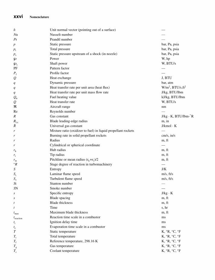
JWST428-fm JWST428-Farokhi Printer: Yet to Come March 13, 2014 11:30 246mm×189mm
xxvi Nomenclature
n Unit normal vector (pointing out of a surface) —Nu Nusselt number —Pr Prandtl number —p Static pressure bar, Pa, psiapt Total pressure bar, Pa, psiaps Static pressure upstream of a shock (in nozzle) bar, Pa, psia℘ Power W, hp℘s Shaft power W, BTU/sPF Pattern factor —Pf Profile factor —Q Heat exchange J, BTUq Dynamic pressure bar, atmq Heat transfer rate per unit area (heat flux) W/m2, BTU/s.ft2
q Heat transfer rate per unit mass flow rate J/kg, BTU/lbmQr Fuel heating value kJ/kg, BTU/lbmQ Heat transfer rate W, BTU/sℜ Aircraft range nmRe Reynolds number —R Gas constant J/kg ⋅ K, BTU/lbm-
◦R
Rl.e. Blade leading-edge radius m, inR Universal gas constant J/kmol ⋅ Kr Mixture ratio (oxidizer to fuel) in liquid propellant rockets —r Burning rate in solid propellant rockets cm/s, in/sr Radius m, ftr Cylindrical or spherical coordinate —rh Hub radius m, ftrt Tip radius m, ftrm Pitchline or mean radius (rh+rt)/2 m, ft◦R Stage degree of reaction in turbomachinery —S Entropy J/KSl Laminar flame speed m/s, ft/sSt Turbulent flame speed m/s, ft/sSt Stanton number —SN Smoke number —s Specific entropy J/kg ⋅ Ks Blade spacing m, ftt Blade thickness m, ftt Time s, hrtmax Maximum blade thickness m, fttreaction Reaction time scale in a combustor msti Ignition delay time mste Evaporation time scale in a combustor msT Static temperature K, ◦R, ◦C, ◦FTt Total temperature K, ◦R, ◦C, ◦FTf Reference temperature, 298.16 K K, ◦R, ◦C, ◦FTg Gas temperature K, ◦R, ◦C, ◦FTc Coolant temperature K, ◦R, ◦C, ◦F
JWST428-fm JWST428-Farokhi Printer: Yet to Come March 13, 2014 11:30 246mm×189mm
Nomenclature xxvii
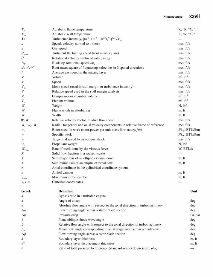
Taf Adiabatic flame temperature K, ◦R, ◦C, ◦FTaw Adiabatic wall temperature K, ◦R, ◦C, ◦FTu Turbulence intensity, [(u
′2 + v′2 + w
′2)∕3]1∕2∕Vm —u Speed, velocity normal to a shock m/s, ft/su Gas speed m/s, ft/su′
rms Turbulent fluctuating speed (root mean square) m/s, ft/s⇀U Rotational velocity vector of rotor; v-reg m/s, ft/sUT Blade tip rotational speed, 𝜔rt m/s, ft/su′, v′, w′ Root mean square of fluctuating velocities in 3 spatial directions m/s, ft/sv Average gas speed in the mixing layer m/s, ft/sV Volume m3, ft3
V Speed m/s, ft/sVm Mean speed (used in stall margin or turbulence intensity) m/s, ft/sV′ Relative speed used in the stall margin analysis m/s, ft/sVc Compressor or chamber volume m3, ft3
Vp Plenum volume m3, ft3
W Weight N, lbfW Flame width in afterburner m, ftW Width m, ft⇀W, W Relative velocity vector, relative flow speed m/s, ft/sWr, W𝜃 , Wz Radial, tangential and axial velocity components in relative frame of reference m/s, ft/swc Rotor specific work (rotor power per unit mass flow rate;℘∕m) J/kg, BTU/lbmw Specific work J/kg, BTU/lbmw Tangential speed to an oblique shock m/s, ft/swp Propellant weight N, lbfWvisc. Rate of work done by the viscous force W, BTU/sX Solid flow fraction in a rocket nozzle —X Semimajor axis of an elliptic external cowl m, ftY Semiminor axis of an elliptic external cowl m, ftz Axial coordinate in the cylindrical coordinate system —z Airfoil camber m, ftzmax Maximum airfoil camber m, ftx, y, z Cartesian coordinates —
Greek Definition Unit𝛼 Bypass ratio in a turbofan engine —𝛼 Angle of attack deg𝛼 Absolute flow angle with respect to the axial direction in turbomachinery degΔ𝛼 Flow turning angle across a stator blade section degΔp Pressure drop Pa, psi𝛽 Plane oblique shock wave angle deg𝛽 Relative flow angle with respect to the axial direction in turbomachinery deg𝛽m Mean flow angle corresponding to an average swirl across a blade row degΔ𝛽 Flow turning angle across a rotor blade section deg𝛿 Boundary layer thickness m, ft𝛿* Boundary layer displacement thickness m, ft𝛿 Ratio of total pressure to reference (standard sea level) pressure; p/pref —

JWST428-fm JWST428-Farokhi Printer: Yet to Come March 13, 2014 11:30 246mm×189mm
xxviii Nomenclature
𝛿T Thermal boundary layer thickness m, ft𝛿* Deviation angle defined at the blade trailing edge, a cascade parameter degΔh0
f (Standard) molar heat of formation J/kmolΔh0
f (Standard) specific heat of formation J/kg𝜀 Tip clearance; slip factor in turbomachinery —𝜀 A small quantity (≪ 1) —𝜀g Emissivity of gas —𝜅 Coefficient of thermal conductivity W/m ⋅ K𝜅1 Blade leading-edge angle in turbomachinery deg𝜅2 Blade trailing-edge angle in turbomachinery deg𝜋 Total pressure ratio —𝜔 Angular speed rad / s, rpm𝜛 Total pressure loss parameter in a cascade; Δpt∕qr —𝜙 Spherical coordinate —𝜙 Equivalence ratio —𝜙 Diffuser wall divergence angle deg𝜙 Flow coefficient; Cz∕U —𝜑 Camber angle, 𝜅1 — 𝜅2 degΦ Cooling effectiveness parameter —𝛾 Ratio of specific heats —Γ Circulation (of a vortex filament), blade circulation m2/s, ft2/s𝛾◦ Cascade stagger angle or blade setting angle deg𝜌 Fluid density kg/m3, lbm/ft3
𝜇 Coefficient of viscosity N ⋅ s/m2
𝜇 Mach angle degreev Kinematic viscosity ≡ 𝜇∕𝜌 m2/s, ft2/sv Prandtl-Meyer angle radians, degree𝜋c Compressor total pressure ratio —𝜋b Burner total pressure ratio —𝜋d Inlet total pressure recovery —𝜋n Nozzle total pressure ratio —𝜋K Temperature sensitivity of chamber pressure in solid rockets %/K, %/FΠM Mach index ≡ UT∕at1 —𝜃 Flow angle, cylindrical or spherical coordinate deg𝜃 Nozzle exit flow angle (from axial direction) deg𝜃 Ratio of total temperature to the reference (standard sea level) temperature; T∕Tref —𝜃 Circumferential extent of the inlet spoiled or distortion sector deg𝜃* Momentum deficit thickness in the boundary layer m𝜎 Cascade or blade solidity; c/s, in turbomachinery —𝜎 Stefan–Boltzmann constant W/m2K4
𝜎p Temperature sensitivity of burning rate in solid propellant grain %/K, %/F𝜏 Shear stress Pa, lbf/ft2, psi𝜏 Total temperature ratio —𝜏 Characteristic timescale s𝜏r, 𝜏s Rotor torque, stator torque in turbomachinery N ⋅ m, ft-lbf𝜏t Turbine total temperature ratio, Tt5∕Tt4 —𝜏𝜆 Cycle limit enthalpy ratio, cptTt4∕cpcT0 —𝜏𝜆AB Limit enthalpy ratio with afterburner, cp,ABTt7∕cpcT0 —𝜏resident Resident timescale ms