an experiment concerning partly closed cavities behind...
TRANSCRIPT
•
Office of Naval Research
Department of the Navy
Contract Nonr-220(43)
AN EXPERIMENT CONCERNING
PARTLY CLOSED CAVITIES
BEHIND A SURFACE-PIERCING ROD
K/ / arman
by M. C. Meijer
•
Hydrodynamics laboratory
Laboratory of Fluid Mechanics and Jet Propulsion
California Institute of Technology
Pasadena, California
Report No. E-110. 1 January 1964
Department of the Navy Office of Naval Research Contract Nonr -220(43)
AN EXPERIMENT CONCERNING PARTLY CLOSED
CAVITIES BEHIND A SURFACE-PIERCING ROD
by
M. C. Meijer
Reproduction in whole or in part is permitted for any purpose of the United States Government
Hydrodynamics Laboratory
Karman Laboratory of Fluid Mechanics and Jet Propulsion
California Institute of Technology
Pasadena, California
Report No. E-110. 1 January 1964
AN EXPERIMENT CONCERNING PARTLY CLOSED
CAVITIES BEHIND A SURFACE-PIERCING ROD
1 . Introduction
by
M. C. Meijer':'
California Institute of Technology
Pasadena, California
Thomsen in Ref. (1 )::o:: emphasizes three different states of ventila-
tion occurring at surface -piercing rods, as observed by Hay (2 ). Hay
has towed cylindrical rods which intersect the water surface, at differ-
ent speeds and at different depths of submergence . From his photogra-
phic records, the following observations have been made.
At relatively low speeds, an air filled cavity is formed in the wake
of the rod, which is open to atmosphere and which extends downwards to
a point above the base of the rod. With increasing speed, this point
moves downward towards the base of the rod. This form of cavity has
been called the "Pre-Base Ventilation State".
After the cavity has reached the base, the state was referred to
as the "Base Ventilation State", which is found to persist with further
increased speed.
>:< Senior Research Engineer, Hydrodynamics Laboratory, California Institute of Technology; on leave from the Technological University of Delft, Holland.
::<>:< Numbers in brackets refer to the references at the end of the text.
After the speed was increased over a certain level, the size of the
cavity was observed to decrease again forming a cavity closed at the
water surface. In this case the state was called the "Post-Base Ven
tilation State" .
Since this last phase in the development of the air -cavity has not
been observed in the Free Surface Water Tunnel at the California
Institute of Technology, it was thought desirable to perform some
experiments in order to find the conditions under which this Post-Base
Ventilation Stat~: can occur .
The present results are to be regarded as preliminary. A full
explanation of the ventilation phenomena described in the references
above and the text of this report to follow is not yet available. Neverthe
less, since the results of the present work are at variance with published
work, it was thought worthwhile to present them now. Hopefully a more
thorough understanding of the ventilation phenomena will be obtained in
the not too distant future.
2. Preliminary Considerations
After reading Thomsen's report, the author considered the possi
bility that the differences between the ventilation states may be caused
by specific differences in flow conditions which seem to appear in a tow
ing tank and in a water tunnel. Especially turbulence, surface tension
and vibration were thought of as possibly responsible for the difference
in behavior at the water surface.
As compared to the Free Surface Water Tunnel, which has no
honeycomb and hardly any settling chamber, the turbulence level in a
2
towing tank must be relatively very low.
With respect to the surface tension properties of the water, it can
be noted that dust may be floating on the surface of the towing tank,
whereas particles in the tunnel will be distributed homogeneously. Vibra
tions of the rod may be mainly structural from the carriage in the towing
tank case and mainly of hydrodynamic origin in the tunnel.
Considering the differences mentioned above, it might be speculat
ed that in the towing tank, closure of the cavity at the water surface will
be more readily achieved than in the Free Surface Water Tunnel.
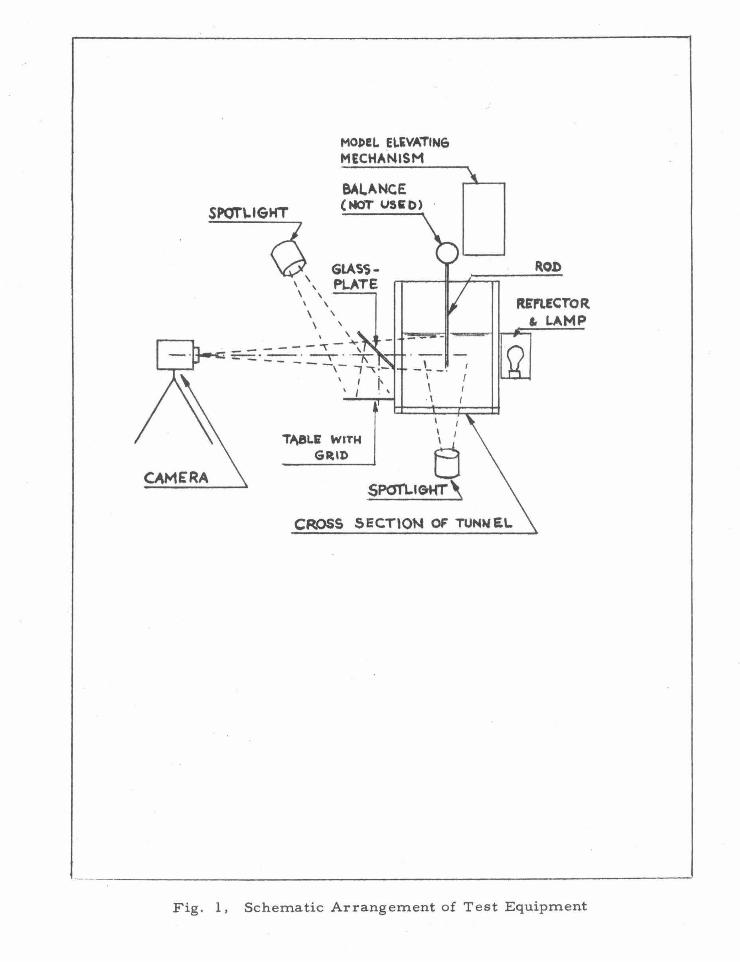
3. Apparatus
The models were fixed to the 3 -component strain gage balance
which has been installed for the Free Surfac e Water Tunnel; no drag
measurements were performed though, as the sensitivity of the balance
(range : 25 lbs.) proved to be too small during the main part of the experi
ments.
In order to facilitate the comparison on the different cavity forms,
a grid divided in tenths of half inches was reflected into the plane of the
cavity with the aid of an inclined glass plate at 45 degrees in front of the
tunnel window.
Photographs were taken through the glass plate. The exposure was
1/25 of a second at F /7. 7 on 250 A. S. A. "Royal Pan" film. The light
ing was supplied by three 7 50 watt lamps at a distance of 3 i feet from
their respective objects, one spotlight pointed at the grid and one at the
cavity, the last one from beneath and slightly downstream in the center
plane of the tunnel. One lamp with separate diffusing reflector from
3
downstream behind the tunnel was used to light the model (see Fig. 1 ).
4. Experimental Procedure
4. 1 In the first experiment a 5/16 inch rod (8mm) was used piercing
the surface at a velocity of about 12 f. p. s. (3. 7 m/ sec). The depth of
submergence was about H = 5 inches (l27mm). According to Fig . 14
of Ref. l, the post-base ventilation state would be expected to occur .
Instead, the cavity was quite open at the top. With the hand or a flat
plate covering the cavity, parallel to and near the free surface, the cavity
could be closed partially. In this case the flow at the surface changed
suddenly, which could be felt, as upward pressure on the means of
closure changed into suction. Air was heard to be sucked through a
small opening between the cover and the rod. After removal of the arti
ficial closure, this condition could persist for some time, but would
soon change again into the open base ventilation state. Total covering
of the surface behind the rod resulted in the entire disappearance of the
cavity, which would always reappear when the cover was removed.
Whether or not the disturbances due to the free stream turbulence are
responsible for this reappearance at this low Froude number is not
known.
In this preliminary experiment no measurements or photographs
were made. The Reynolds number based on the rod diameter was of
the order of 3Xl 04 • The same observations have been made with a
1/8 inch rod submerged to 3-5/8 inch depth. The extreme velocity in
this case was 20.75 feet per second.
4. 2 In order to obtain subcritical flow conditions with respect to the
4
Reynolds number comparable to those in Hay's experiments, a rod with
a diameter of 1/8 inch (3 mm) was select~d and the tunnel was run at a
velocity of 3. 94 ft. I sec. (1 . 2. m/ sec.). Now the Reynolds number was
about 3. 8 X 1 fY . The tunnel velocity was too low for proper super cri
tical operation, (now with respect to the channel Froude number) but as
the actual and local water surface was measured, the velocity, as calcu
lated,was considered to be approximately correct, although it should be
noted that some change of velocity near the surface must have been pre
sent due to some curvature of the surface then.
The ventilation state in this experiment was varied by changing
the submergence depth of the rod. At a depth of about 0. 138 ft. (42. mm)
a transient condition occurred in which the form of the cavity changed
considerably and generally at a slow pace with time as discussed in the
next section.
4. 3 With a 1/4 inch rod (-6. 3 mm) a transient condition was found
with a velocity of 5.44 ft. /sec. (1.66 m/sec. ), the Reynolds number
being about l X 104 • In this case the changing of form was much more
abrupt, and to photograph the different forms of the cavity, the submer
gence depth had to be adjusted. With the lower velocity of 4ft. I sec.
(1 . 2.2. m/ sec. ) again a more stable transition form was obtained.
5. Analysis of Data
5. 1 The process of the change of form mentioned in 4. 2 can be de
scribed as shown in the photographs of Fig. 3. Photograph 2 shows the
open form obtained after shaking of the rod in the direction of the flow.
The length of the cavity just below the water surface may vary some-
5
what, depending upon the intensity of the shaking procedure. In the
region of the extremity of the cavity downstream, near the water sur
face, a small indication of a re-entrant jet exists, seen in the side
e levation of the cavity.
This open condition may persist for some time, but then the
cavity slowly becomes shorter and the "re-entrant jet" becomes a
small "bay", as shown in photograph 6 (also in 1 and 7 ). The "bay"
seems to proceed along a definite curve which is independent of the
submergence depth. (Photographs 5 and 9).
When the "bay" reaches the rod, the cavity is cut in two. Presum
ably, because of surface tension effects, a third bubble is formed in
between, and thin films of water may divide the lower and upper bubbles,
however, not interfering with the general shape of the cavity in these
instances (see photograph 3).
It must be noted, that surface tension will play a role in this case
where the dimensions and hydrodynamic forces are small.
If the end of the rod is too far away, as is the case in photographs
8, 9, and 10, the closure between the bubbles will be complete and the
lower bubble will disappear (photograph 10). In the case of photograph
3, the presence of the end of the rod seems to promote the leakage of
air from the top bubble into the lower one.
The most stable form of the series seems to be that of photograph
4, which occurs after the lower boundary of the upper bubble and the
upper boundary of the lower bubble have merged into each other, which
occurs suddenly. In this case the two bubbles remain separated by a
6
film of water, the length of the cavity just below the water surface be- ·
comes shorter and, what is the most remarkable feature, the lower
end of the upper bubble forms a "flag" of a rough texture, which always
extends from a line about vertical through the end of the lower bubble,
to the curve of the original open cavity (photograph 2 ). All the forms in
the photographs numbered 3 through 6 remain within the boundary of the
open form and the curvature near the end of the rod remains approxi
mately the same. The length of the top of the cavity only changes con
siderably at the last instant (photograph 4 ).
When the submergence depth is reduced, only a small "bay" is
formed as is shown in photograph 7, after which the form remains the
same. With a larger submergence depth, the lower bubble disappears,
as is mentioned earlier. In photographs 8 and 9, the length of the
cavity near the surface appears to be larger than was the case in the
previous series, but this may be caused by the amount of shaking
applied.
In the case of photograph 10, where the lower cavity has disap
peared, the lower end of the remaining cavity is situated at exactly the
same place as the division of the bubbles in photograph 10 (and 11) it
is also noted that the streamlines at the lower boundary of a remaining
upper-cavity are headed downwards.
5. 2 Being acquainted with the proceedings described above, it is possi
ble to guess the same general configuration at higher Reynolds numbers,
photographed in 12 and 13 for the thin rod and 14 through 18 for the 1/4
inch rod. In the case of the longer rod, the curve (see Fig. 2) along
7

which the "bay" proceeds seems to have moved downwards with the end
of the rod; where the rod is thicker, the curve may have been moved
upward, even above the free water surface.
In the case of photograph 18 the rear boundary of the lower bubble
curls inwards and forms the separate bubble which can be seen within
the top of the cavity attached to the rod.
5. 3 The cavity shown in photograph 11 is of interest because of its
separations. In this case the submergence depth is large; the end never
carried a cavity. The position of the vertical separation film in the
cavity is quite stable. The bubbles behind this line can be entrained by
the flow, leaving the forward cavity unaltered. This may be important, as
in the experiments described under 4. 1 it was already observed that the
length of the cavity, after opening of the water surface changed in steps
rather than continuously.
5. 4 About photograph 15, it is noted that during this series the submer
gence depth was mechanically limited to 0. 304 ft. , in which range it prov
ed to be impossible to make the lower cavity disappear. Photograph 15
now was obtained with a turbulence stimulating rod of 1/8 inch diameter
which was held at a 2 foot distance upstream of the model.
5. 5 Concerning the form of the cavity at the intersection with the water
surface, the following remarks can be made:
At relatively low Reynolds numbers, the surface appears to be
partly closed all the time. Even in the case of photograph 2 it is prob
able that a small pressure drop at the air -entrance existed. Only in
the case of photograph 17 is it certain that the surface is entirely open.
8
The hypothesis can be made that this is caused by the position of the
curve of the "bay-points" being above the water surface.
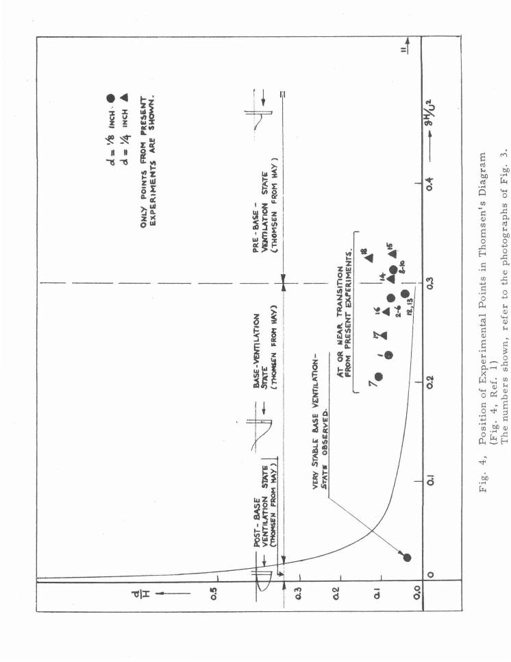
6. Comment on Thomsen's Diagram
In Fig. 4 of Ref. 1, Thomsen showed the dependency of the flow
states from the ratio d/H, the inverted square of the Froude number
gH/Uz and Reynolds number Re based on the diameter.
The symbols used are:
d = diameter
H = depth of submergence
g = accel eration of gravity
U = velocity
This diagram has been reproduced at the same scale in Fig. 4 of
this report. Hay's experimental points have been replaced by points
representing the photographs of Fig. 3 and one extreme condition.
It is thought, that replacement of gH/U z by its inverted value,
i.e. uz/gH, makes a better picture. In Fig. 5 d/H has been plotted
against U z; gH. The black dots represent the experimental data re
ported here; the open symbols are taken from Thomsen's diagram and
indicate the onset of the post-base ventilation state. The dot at the
extreme right of the diagram shows the extreme condition, at which
still no post-base ventilation state could be obtained in a natural way.
The approximate linearity of the average transition line between
the base- and post-base ventilation state, as derived from Hay's ex
periments, indicate that this phenomenon is little dependent of the sub
mergence depth H, which seems to be valid also where d/H = 1. It
can hardly be plausible, that this is related to the underwater flow. This
9
seems to point at influences above the surface, such as the increase of
the height of the spray sheet with increasing speed, which should be
proportional to U z.
If such a spray sheet makes contact with a plate or other cover,
parallel to the water surface, than it has been shown that the cavity
obtains a shape in agreement with the description of the post-base
ventilation state.
7. Conclusions
Although experiments have been made at very low values of gH/Uz
and low values of d/H, the post-base ventilation state, as described
by Thomsen, did not occur in the Free Surface Water Tunnel in a
natural manner. It could be obtained by partial closure of the gap in
the water surface with a plate. Removal of this plate resulted always
in a restoration of the original base ventilated state if the velocity was
high enough.
It seems reasonable to suppose that in the case of Hay's experi
ments such a plate or other spray cover near the surface must have
been present, which became effective at high velocities, when the spray
sheet could make good contact with it. At the transition of the pre-base
ventilation state and the base ventilation state, stable cavities did exist
which were nearly closed near the water surface, or at a lower point.
10
REFERENCES
1. Thomsen, P., "Cavity Shape and Drag in Ventilated Flow; Theory
and Experiment", TRG,Inc. Report 156 SR-2, 2 Aerial Way,
Syosset, New York, February, 1963.
2. Hay, A. D., "Flow About Semi-Submerged Cylinders of Finite
Length", Princeton University, October 1, 1947.
11
ACKNOWLEDGMENT
The author is indebted to the University of Technology of Delft,
the Netherlands, to "The Netherlands Organization for the Advance
ment of Pure Research, "Z. W. 0. ", which supported his visit to the
California Institute of Technology, and to the personnel of the Institute
who assisted him when it was needed.
This work was supported by the U. S . Office of Naval Research
under Contract Nonr -220(43 ).
12
13
APPENDIX I
Data Sheet
Rod d = l inch, position vertical.
Water level at rest above bottom F. S. W. T . = 1. 434ft. at which the model
raising mechanism is set with the end of the rod touching the water surface.
Grid reflection in optical plane under water of rod, divisions are in 1 I 10
of 1 /2 inch.
Drag readings are of the same magnitude as the drift of the apparatus .
Barometer reading: 29. 4 inch Mercury at 72° F.
Camera setting: 1/25 sec. F/7. 7.
Film sensitivity: 250 A. S. A.
Lighting: 1 spotlight 750 W, distance: 3! 1, directed at grid.
Number of Picture
1
2
3
4
5
6
1 spotlight 750 W, distance: 3! 1, directed at rear
end of cavity from underneath and downstream.
Velocity Reading
Feet
1. 595
1. 565
1. 565
1. 565
1. 565
1. 565
Water Level Above Bottom
Feet
1.311
1. 322
1. 322
1. 322
1.322
1. 322
Rod-End Level
Feet
1. 183
1. 184
1. 184
1. 184
1. 184
1. 184
Remarks
trial for exposure data
long cavity after shaking of rod; sometimes natural condition
natural condition, rear end of top cavity often with bubbles
less stable
more stable
14
APPENDIX I
Data Sheet (continued)
Rod d = t inch, position vertical
Number of Velocity Water Level Rod-End Remarks Picture Reading Above Bottom Level
Feet Feet Feet
7 l. 565 1.322 1.205 only stable condition
8 l. 565 l. 322 l. 170 after longitudinal shaking
9 l. 565 1.322 l. 170 less stable
10 l. 565 1. 322 1. 170 stable
11 l . 565 l. 322 0. 988 only stable form apart from rear end bubbles
12 1.690 1.229 0. 964 just changing form
13 l. 690 1.229 0. 964
14 1. 698 I. 235 0. 954 transition
15 l. 698 1. 235 0. 931 with aid of turbulence rod i" at 2 ft upstream
16 l. 700 1. 235 0. 985 quite stable, transition
17 l. 700 1. 235 1. 007 very stable
18 1. 573 l. 322 1. 159
APPENDIX II
Calculation of velocity and submerged height of rod , ~ and b~
Barometer not corrected: 29.4 inch Hg at 72° F.
Rod diameter d = j inch = 0. 0032 m
Photograph No. 1 2-6
Vel. reading inft. HO 1. 595 1. 565 2
Local water level in ft. 1. 311 1. 322
Vel. head in ft. H 0 0. 284 0. 243 z
86.5 74.0
u"- in (m/ sec. )z 1. 69 1. 45
U in m / sec. 1. 3 0 1 . 2 0
U in f. p. s. 4. 26 3. 94
Local water level in ft . 1. 311 1. 322
Leve1ofrodbaseinft. 1.183 1. 184
Submerged ht. in ft. 0. 128 0 . 138
7 8-10
same same
1. 45 1. 45
1.20 1.20
3. 94 3. 94
1. 322 1. 322
1.205 1.170
0.117 0.152
11
same
1. 45
1. 20
3. 94
1. 322
0.988
0 . 334
Same in m (H) 0. 0390 0. 0420 0. 0305 0. 0463 0. 1017
d/H 0. 082 0. 076 0. 105 0. 069 0. 031
gH/U2 0.227 0. 284 0. 206 0. 313 0.688
Re = Ud/v 3 . 8X 1 o3 3 . 5X 1 03 3. 5X 1 o3 3 . 5X 1 03 3. 5X 1 03
12-13
1.690
l. 229
0 . 461
140.4
2.75
l. 66
5.44
1. 229
0. 964
0. 265
0 . 0807
0. 040
0.288
4.8X1 o3
15
16
APPENDIX II (continued)
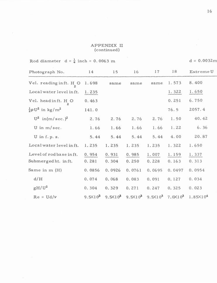
Rod diameter d = ~ inch = 0. 0063 m d = 0.0032m
Photograph No. 14 15 16 17 18 ExtremeU
Vel. reading in ft. HO z
l. 698 same same same l. 573 8.400
Local water level in ft. 1.235 l. 322 1.650
Vel. head in ft. H 0 0.463 0.251 6.750 z
1-PUz in kg/mz 141. 0 76.5 2057.4
uz in(m/ sec. )z 2.76 2.76 2.76 2.76 l. 50 40.42
U in m/ sec. l. 66 l. 66 l. 66 l. 66 l. 22 6. 36
U in f. p. s. 5.44 5.44 5.44 5.44 4.00 20.87
Lo~al water level in ft. l. 235 l. 235 l. 235 l. 235 l. 322 l. 650
Level of rod base in ft. 0. 954 0. 931 0. 985 l. 007 l. 159 l. 337
Submerged ht. in ft. 0.281 0. 304 0.250 0.228 0. 163 0. 313
Same in m (H) 0. 0856 0. 0926 0. 0761 0. 0695 0. 0497 0. 0954
d/H 0. 074 0. 068 0.083 0. 091 0. 127 0 . 034
gH/Uz 0. 304 0. 329 0.271 0.247 0. 325 0 . 023
Re = Ud/v 9. 5Xl o3 9.5Xlo3 9. 5Xl o3 9. sx1 o3 7.0Xlo3 L85Xl o4
SPOT'\..IGHT
MOJ>!L ELiVATING MECHANISM
BALANCE (MOT VSED)
~' ' '
GLAS$PLATE
CAMERA
' ' \ ' ' \ \ '
\ ' . -- ____ ,- .... , . -::-:::. -- . ----- . . I\ - - - - -,- ....., '.-
\\ / ~ \
\ ' -~ - · I \ I · I I
I
TI\BL.I WJTH ~ GRID u
SP<m..l<:rHT \
CROSS SECTtON OF TUNNEL
ROJ)
RinECTOR & LAMP
Fig. 1, Schematic Arrangement of Test Equipment
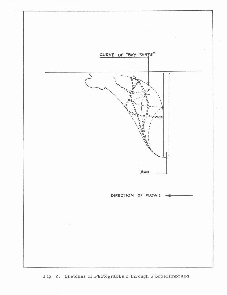
CURVE OF "BAY ~IHTS"
ROD
biR~CTION OF FLOW: ... -4.------
Fig. 2. Sketches of Photographs 2 through 6 Superimposed.
' I ~ 1 i I I ,./ , I
f ~ ;_t ...
l. d = ~ in. = 3. 2 mm U = 4. 26 f. p. s. = l. 30m/ sec H=O.l28ft =39.0mm
2. After shaking of rod d = ~ in. = 3. 2 mm
U = 3. 94 f. p. s. = 1. 20m/ sec H = 0. 138 ft = 42. 0 mm
3. Developed from 2, same data
4. Same as 3
5. Same as 3, unstable transient form
6. Same as 3
Fig. 3 Photographs of Rod in Water Tunnel. The flow is from right to left. In each case the diameter of the rod d, speed of water U and depth of r od H is listed. The ambient pressure was 29. 1 in. Hg (9. 800 kg/m2 ) at 72°F (20° C). The large grid squares are one half of an inch on a side.
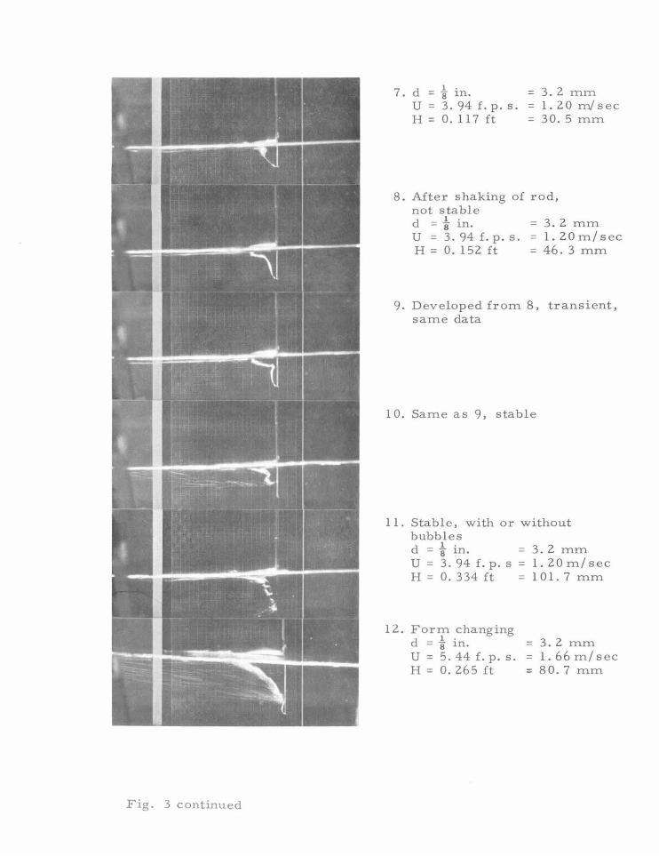
F ig. 3 continued
7 d 1 · = 3. 2 mm . = 8 1n.
U = 3. 94 f. p. s. = 1. 20 m/ sec H = 0. 11 7 ft = 3 0 . 5 mm
8. After shaking of rod, not stable d = i in. = 3. 2 mm U = 3. 94 f. p. s. = 1 . 2 0 m / sec H = 0. 152 ft = 46. 3 mm
9. D eveloped from 8, transient, same data
10. Same as 9, stable
11. Stable , with or without bubbles d = i in. = 3 . 2 mm U = 3. 94 f.p. s = 1. 20m/sec H = 0. 334ft = 101. 7 mm
12. Form chang ing d = i in. = 3 . 2 mm U = 5. 44 f. p. s. = 1. 66 m/ sec H = 0. 265 ft = 80. 7 mm
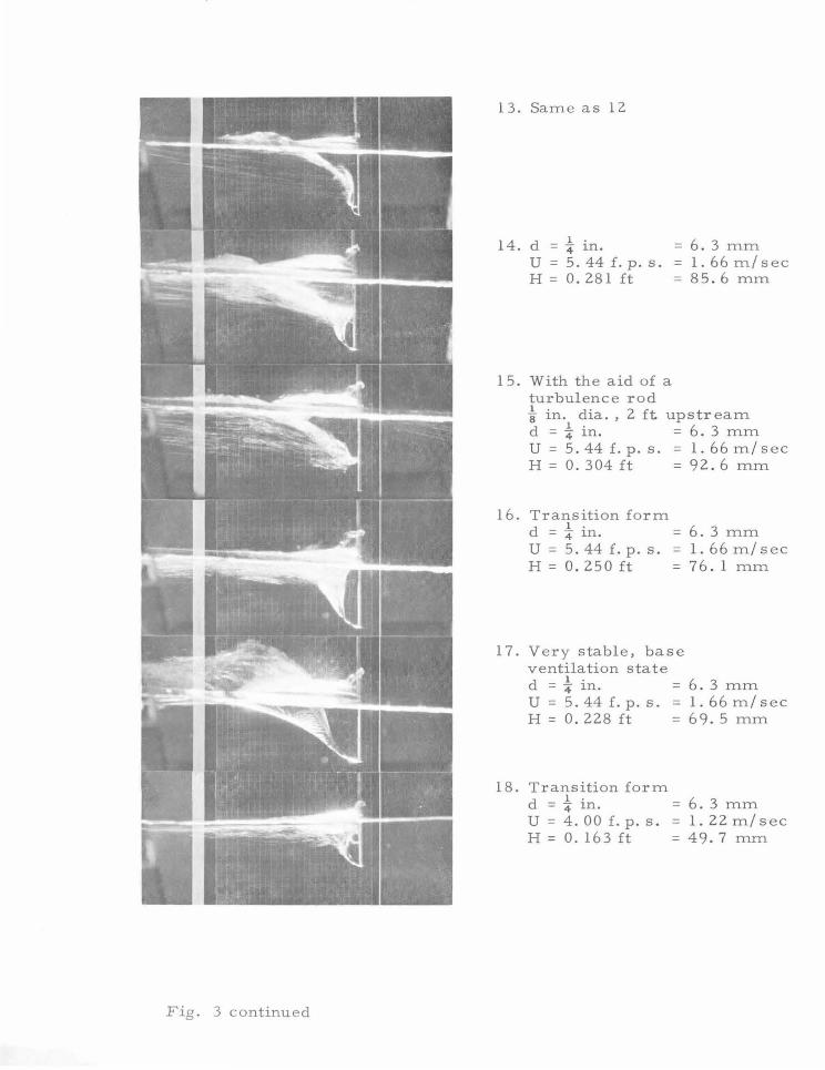
Fig. 3 continued
13. Same as 12
14. d = i in. = 6. 3 mm U=5.44f.p.s. =1.66m/sec H = 0.281 ft = 85.6 mm
15. With the aid of a turbulence rod i in. dia. , 2 ft upstream d = i in. = 6. 3 mm U=5.44£.p.s. =1.66m/sec H = 0. 304 ft = 92. 6 mm
16. Transition form d = -i" in. = 6. 3 mm U = 5. 44 f. p. s. = 1. 6 6 m I s e c H = 0. 2 50 ft = 7 6. 1 mm
17. Very stable, base ventilation state
18.
d = i in. = 6. 3 mm U = 5. 44 f. p. s. = 1. 66 m/ sec H = 0. 2 2 8 f t = 6 9. 5 mm
Transition form d
1 . = 4 1n. u = 4. 00 f. p. s. H = 0. 163ft
= 6. 3 mm =1.22m/sec = 49.7 mm
d H 1 o.o
0
cJ..
·~
IHa
l·
.
d • ~
INC
H
A
ON
LY
P
OIN
TS
F
RO
M f'R£~£NT
EXP~~IMEMTS A~r
SH
OW
N.
PO
ST
-BA
SE
" ~
VE
NT
ILA
TIO
N S~TE I
--~N
FRO
M A
AY
}
BA
SE -
VB
mL
AT
ION
""'T
£
C 71
'40M
S&N
FR
Of'f
MA
Y)
PR
.E-&
AS
E
Vil
mL
AT
ION
ST
ATE
(T
HO
MS
EN
F~M
HA
Y)
~__:
I
_I~
T
VE
RY
S
TA
aL
£
t.AS
E
Y£
NT
I&.A
TIO
N
.ST
AT
.-O
&S
ER
VE
D·
I
0.1
AT
OR
W
EA
k T
RA
tllS
tno
t(
FRO
M
PR
ES
EN
T E
XP
'EIU
ME
NT
S.
r I
,;.• 7
,.,
,,
•+
II"
e e
A ..... .
~. ... •
I a-
to ---------------~~~·~•s=
0.2
0.3
Fig
. 4
, P
osi
tio
n o
f E
xp
eri
men
tal
Po
ints
in
Th
om
sen
's D
iag
ram
(F
ig.
4,
Ref
. 1
) T
he n
um
bers
sh
ow
n,
refe
r to
th
e p
ho
tog
rap
hs
of
Fig
. 3
.
~ t
tifu
1
..!!.
.

cl H
PA£-~£-ANO
81\5
£ -V
f:tf
TIL
Al"
IOH
.S
TAlE
T
MN
&IT
ION
LI
NIL
IS
IN
A
6Rii
&M
EN
T
wm
f · THOMS£~ 'S
18~
-~
I
I
7 I
D
0 a
/--
/
/
/ /
/
/ /
1 --i
-.1!'
I I R
£610
N
OF
DIS
PU
TE
D T
RA
NS
ITfO
H
1 B
E'T
'WiiE
N
&A
SE
·A
ND
~r
-BA
SE
/
/
II D.~
-il
PU
-8A
U I
7e
0.101
I ·~ " .. , J.
~-6
1.10
~
.
<lD
!iL
I ~1
2.3
I I
"• l
b /
II
I I
/
I /
/
I ,
I I
I I
I I
I I
I V
EN
TIL
AT
ION
ST
A"T
l /
POST
" e.
\5£
(~ROM T
HO
MS
EN
) ,
/
/
/
/ /
/ ~
---------··
-----..
. ...
-'j
FU
LL sYMBol.$~
PR
fS!N
T ~PER
IMENT'S
OP
OI
SYM
BO
LS
AR
E A
AO
M n
40
"'fW
N
---
-----
--
· -·
---
---
---
----
--
---
/ /
/
o 1a
/
!:::.
/0
/ I
I I 0
/
/
/
/
/
/ /
/
/
/ /
10
J 2.0
Ex
Tft
EM
E
CO
ND
ITIO
N ~
WH
ICH
NO
POsr-~E
YllN
TII
.AT.
tON
$T
IJi
HI\
$ &
E£'
N O
BSE
'RV
ED
I 30
-u&
tH
--....
I 40
Fig
. 5
, D
iag
ram
of
Fig
. 4
on
In
vert
ed
Base
. T
he n
um
bers
sh
own
, re
fer
to t
he
ph
oto
gra
ph
s o
f F
ig.
3.
----------------------------------------~--------------- -----
DISTRIBUTION LIST FOR UNCLASSIFIED TECHNICAL REPORTS
ISSUED UNDER
CONTRACT Nonr 220(41)
(Single copies unless otherwis e specified)
Chief of Naval Research Department of the Navy Washington 25, D. C. Attn: Code s 438 ( 3)
461 463 466
Commanding Officer Office of Naval Research Branch Office 495 Summe r Street Boston 10 , Massachusetts
Commanding Officer Office of Naval Research Branch Offi c e 207 West 24th Street New York 11, New York
Commanding Officer Office of Naval Research Branch Office 1 0 30 East Green Street Pasadena, California
Commanding Officer Office of Naval Research Branch Office 1000 Geary Street San Francisco 9, California
Commanding Officer Office of Naval Research Branch Offi c e Box 39, Navy No. 100 Fleet Post Office New York, New York (25)
Director Naval Research Laboratory Washington 25, D . C . Attn: Code 2027 (6)
Chief, Bureau of Naval Weapons Department of the Navy Washington 25, D. C. Attn: Codes RUAW -r
Commander
RRRE RAAD RAAD-222 DIS-42
U. S. Naval Ordnance Test Station China Lake, California Attn: Code 753
Chief, Bureau of Ships Department of the Navy Washington 25, D. C. Attn: Codes 310
312 335 420 421 440 442 449
Chief, Bureau of Yards and Docks Department of the Navy Washington 25 , D. C. Attn: Code D-400
Commanding Officer and Director David Taylor Model Basin Washington 7, D. C. Attn: Codes 108
Commander
142 500 513 520 525 526 526A 530 5 33 580 585 589 591 591A 700
U.S. Naval Ordnance Test Station Pasadena Annex 3202 E. Foothill Blvd. Pasadena 8, California Attn: Code P-508
Commander Planning Department Portsmouth Naval Shipyard Portsmouth, New Hampshire
Commander Planning Department Boston Naval Shipyard Boston 29, Massachusetts
2
Commander Planning Department Pearl Harbor Naval Shipyard Navy No. 128, Fleet Post Office San Francisco, California
Commander Planning Department San Francisco Naval Shipyard San Francisco 24, California
Commander Planning Department Mare Island Naval Shipyard Vallejo, California
Commander Planning Department New York Naval Shipyard Brooklyn 1, New York
Commander Planning Department Puget Sound Naval Shipyard Bremerton, Washington
Commander Planning Department Philadelphia Naval Shipyard U. S. Naval Base Philadelphia 12, Pennsylvania
Commander Planning Department Norfolk Naval Shipyard Portsmouth, Virginia
Commander Planning Department Charleston Naval Shipyard U. S. Naval Base Charleston, South Carolina
Commander Planning Department Long Beach Naval Shipyard Long Beach 2, California
Commander Planning Department U. S. Naval Weapons Laboratory Dahlgren, Virginia .
Commander U. S. Naval Ordnance Laboratory White Oak, Maryland
Dr . A. V. Hershey Computation and Exterior
Ballistics Laboratory U. S. Naval Weapons Laboratory Dahlgren, Virginia
Superintendent U. S. Naval Academy Annapolis, Maryland Attn: Library
Superintendent U. S. Naval Postgraduate School Monterey, California
Commandant U. S. Coast Guard 1300 E. Street, N. W. Washington, D. C.
Secretary Ship Structure Committee U. S. Coast Guard Headquarters 1300 E Street, N. W. Washington, D. C.
Commander Military Sea Transportation Service Department of the Navy Washington 25, D. C.
U. S. Maritime Administration GAO Building 441 G Street, N. W. Washington, D. C. Attn: Division of Ship Design
Division of Research
Superintendent U. S. Merchant Marine Academy Kings Point, Long Island, New York Attn: Capt. L. S. McCready
(Dept. of Engineering)
Commanding Officer and Director U. S. Navy Mine Defense Laboratory Panama City, Florida
Commanding Officer NROTC and Naval Administrative Massachusetts Institute of Technology Cambridge 39, Massachusetts
U. S. Army Transportation Research and Development Command
Fort Eustis, Virginia Attn: Marine Transport Division
Mr. J. B. Parkinson National Aeronautics and Space
Administration 1512 H Street, N. W. Washington 25, D. C.
Director Langley Research Center Langley Station Hampton, Virginia Attn: Mr. I. E. Garrick
Mr. D. J. Marten

Director Engineering Sciences Division National Science Foundation 1951 Constitution Avenue, N. W. Washington 25, D. C.
Director National Bureau of Standards Washington 25, D . C. Attn: Fluid Mechanics Division
(Dr. G. B. Schubauer) Dr. G. H. Keulegan Dr. J. M. Franklin
Defense DocurnPntation Center Cameron Station Alexandria, Virginia (20)
Office of Technical Services Department of Commerce Washington 25, D. C.
California Institute of Technology Pasadena 4, California
Harvard University Cambridge 38, Massachusetts Attn : Professor G. Birkhoff
(Dept. of Mathematics) Professor G. F. Carrier
(Dept. of Mathematics)
University of Michigan Ann Arbor, Michigan Attn: Professor R. B. Couch
(Dept. of Naval Architecture) Professor W. W. Willmarth
(Aero. Engineering Department)
Dr, L. G. Straub, Director St. Anthony Falls Hydraulic Laborato!'y University of Minnesota Minneapolis 14, Minnesota Attn: Mr. J. N. Wetzel
Professor B. Silberman
Professor J. J. Foody Engineering Department
3
Attn: Professor M. S. Plesset Professor T. Y. Wu Professor A, J. Acosta New York State University Maritime College
Fort Schulyer, New York University of California Department of Engineering Los Angeles 24, California Attn: Dr. A. Powell
Director Scripps Institute of Oceanography University of California La Jolla , California
Professor M. L. Albertson Department of Civil Engineering Colorado A and M College Fort Collins, Colorado
Professor J. E. Cermak Department of Civil Engineering Colorado State University Fort Collins, Colorado
New York University Institute of Mathematical Sciences 25 Waverly Place New York 3, New York Attn: Professor J. Keller
Professor J. J. Stoker
The Johns Hopkins University Department of Mechanical Engineering Baltimore 18, Maryland Attn: Professor S. Corrsin
Professor 0. M. Phillips (2)
Massachusetts Institute of Technology Department of Naval Architecture and
Marine Engineering Cambridge 39, Massachusetts Attn: Professor M. A. Abkowitz, Head
Professor W. R. Sears Dr. G. F . Wislicenus Graduate School of Aeronautical Engineering Ordnance Research Laboratory Cornell University Pennsylvania State University Ithaca, New York University Park, Pennsylvania
State University of Iowa Iowa Institute of Hydraulic Iowa City, Iowa Attn: Dr. H. Rouse
Dr. L. Landweber
Research
Massachusetts Institute of Technology Cambridge 39, Massachusetts Attn: Department of Naval Architecture
and Marine Engineering Professor A. T. Ippen
Attn: Dr. M. Sevik
Professor R. C. DiPrima Department of Mathematics Rensselaer Polytechnic Institute Troy, New York
Director Woods Hole Oceanographic Institute Woods Hole, Massachusetts
4
Stevens Institute of Technology Davidson Laboratory Castle Point Station Hoboken, New Jersey Attn: Mr. D. Savitsky
Mr. J. P. Breslin Mr. C. J. Henry Mr. S. Tsakonas
Webb Institute of Naval Architecture Crescent Beach Road Glen Cove, New York Attn: Professor E. V, Lewis
Technical Library
Executive Director Air Force Office of Scientific Washington 25 , D. C. Attn: Mechanics Branch
Commander
Research
Wright Air Development Division Aircraft Laboratory Wright-Pattern Air Force Base, Ohio Attn : Mr. W . Mykytow, Dynamics
Branch
Cornell Aeronautical Laboratory 4455 Genesee Street Buffalo, New York Attn: Mr. W. Targoff
Mr. R. White
Massachusetts Institute of Technology Fluid Dynamics Research Laboratory Cambridge 39, Massachusetts Attn: Professor H. Ashley
Professor M. Landahl Professor J. Dugundji
Ships mode 11 tanken Trondheim , Norway Attn : Professor J, K. Lunde
Versuchsanstalt fur Wasserbau and Schiffbau
Schleuseninsel im Tiergarten Berlin, Germany Attn : Dr. S. Schuster, Director
Dr . Grosse
Technische Hogeschool Institut voor Toegepaste Wiskunde Julianalaan 132 Delft, Netherlands Attn: Professor R. Timman
Bureau D'Analyse et de Recherche Appliquees
47 Avenue Victor Bresson Is sy- Les -Moulineaux Seine, France Attn: Professor Siestrunck
Netherlands Ship Model Basin Wageningen, The Netherlands Attn: Dr, Ir. J . D. vanManen
National Physical Laboratory Teddington, Middlesex, England Attn: Mr. A. Silverleaf, Superintendent
Ship Division Head, Aerodynamics Division
Head, Aerodynamics Department Royal Aircraft Establishment Farnborough, Hants, England Attn: Mr. M . 0. W. Wolfe
b · h s h'ffb y h 1 Dr. S . F . Hoerner Ham urg1s c e c 1 au- ersuc sansta t 148 Bus teed Drive Bramfelder Strasse 164 Midland Park New Jers e y Hamburg 33, Germany ' Attn: Dr. H . Schwanecke Boeing Airplane Company
Dr. H. W. Lerbs_ Seattle Division
Institut fur Schittbau der Universitat Hamburg
Berliner Tor 21 Hamburg 1, Germany Attn: Prof. G . P . Weinblum
Seattle, Washington Attn: Mr. M. J. Turner
Electric Boat Division General Dynamics Corporation Groton , Connecticut
Transportation Technical Research Institute Attn: Mr. Robert McCandliss
1-1057 , M e jiro-Cho, Toshima-Ku General Applied Sciences Labs., Inc. Tokyo, Japan Merrick and Stewart Avenues
M Pl k I t 't t f St f h Westbury, Long Island, New York ax- anc ns 1 u ur romungs orsc ung Bottingerstrasse 6/8 Gibbs and Cox, Inc . Gottingen, Germany 21 West Street Attn : Dr . H. Reichardt New York, New York
Hydro-og Aerodynamisk Laboratorium Lyngby, Denmark Attn : Profe sso r Carl Prohaska
Lockheed Aircraft Corporation Missiles and Space Division P ala Alto, Calif a rni a Attn: R. W . Kermeen
Grumman Aircraft Engineering Corp. Bethpage, Long Island, New York Attn: Mr. E. Baird
Mr. E . Bower Mr. W. P. Carl
Midwest Research Institute 425 Volker Blvd. Kansas City l 0, Missouri Attn: Mr. Zeydel
Director, Department of Mechanical Sciences
Southwest Research Institute 8500 Culebra Road San Antonio 6, Texas Attn: Dr. H. N. Abramson
Mr. G. Ransleben Editor, Applied Mechanics
Review
Convair A Division of General Dynamics San Diego, California Attn : Mr. R. H. Oversmith
Mr. H. T. Brooke
Hughes Tool Company Aircraft Division Culver City, California Attn: Mr. M. S. Harned
Hydronautics, Incorporated Pindell School Road Howard County Laure l, Maryland Attn: Mr. Phillip Eisenberg
Rand Development Corporation 1 3600 Deise Avenue Cleve land 1 0, Ohio Attn: Dr. A. S. Iberall
U. S. Rubber Company Research and Development Department Wayne, New Jersey Attn: Mr. L. M . White
Technical Research Group, Inc. Route 110 Melville, New York, 11749 Attn: Mr. Jack Kotik
Mr. C. Wigley Flat 102 6-9 Charterhouse Square London, E. C. 1 , England
AVCO Corporation Lycoming Division 1701 K Street, N. W. Apt. No. 904 Washington, D. C. Attn: Mr. T . A. Duncan
Mr. J. G. Baker Baker Manufactu dng Company Evansville, Wisconsin
Curtiss-Wright Corporation Research Division
Turbomachine ry Division Quehanna, Pennsylvania Attn: Mr. George H. Pedersen
Dr. Blaine R. Parkin AiResearch Manufacturing Corporation 9851-9951 Sepulveda Boulevard Los Angeles 45, California
The Boeing C ompany Aero-Space Divisio n Seattle 24, Washington Attn: Mr. R. E. Bateman
(Internal Mail Station 46-74)
Lockheed Aircraft Corporation California Division Hydrodynamics Research .Burbank, California Attn: Mr. Bill East
National Research Council Montreal Road Ottawa 2, Canada Attn: Mr. E. S. Turner
The Rand Corpo ration 1 700 Main Street Santa Monica, California Attn: Technical Library
Stanford University Department of Civil Engineering Stanford, California Attn: Dr. Byrne Perry
Dr. E. Y. Hsu
Dr. Hirsh Cohen IBM Research Center P. 0. Box218 Yorktown Heights , New York
Mr. David Wellinger Hydrofoil Projects Radio Corporation of America Burlington, Massachusetts
Food Machinery Corporation P. 0. Box 367 San Jose, California Attn: Mr. G. Tedrew
Dr. T. R. Goodman Oceanic s, Inc. Technical Industrial Park Plainview, Long Island, New York
5
6
Professor Brunelle Department of Aeronautical Engineering Princeton University Princeton, New Jersey
Commanding Officer Office of Naval Research Branch Office 230 N. iv1ichigan Avenue, Chicago 1, Illinois
University of Colorado Aerospace Engineering Sciences Boulder, Colorado Attn: Prof. M. S . Uberoi
The Pennsylvania State University Dept. of Aeronautical Engineering Ordnance Research Laboratory P. 0. Box 30 State College, Pennsylvania Attn: Professor J. William Holl
Institut fur Schiffbau der Universitat Hamburg Lammersieth 90 2 Hamburg 33, Germany Attn: Dr. 0. Grim