an ultra high throughput x-ray astronomy observatory … · an ultra high throughput x-ray...
TRANSCRIPT

Final Report
March 2002
An Ultra High Throughput X-ray Astronomy ObservatoryWith a New Mission Architecture
Grant-16717066
Prepared for
NASA Institute for Advanced ConceptsUSRA
Smithsonian InstitutionAstrophysical Observatory
Cambridge, Massachusetts 02138
The Smithsonian Astrophysical Observatory
is a member of the
The Smithsonian Astrophysical Observatory
is a member of the
Harvard-Smithsonian Center for Astrophysics

Abstract
An Ultra-High Throughput X-Ray Telescope (UXT) Observatory With a New Mission Architecture
Paul Gorenstein
Harvard-Smithsonian Center for Astrophysics Over a two year period with the support of a grant from the NASA Institute for Advanced Concepts (NIAC/USRA Grant No. 7600-035) we addressed the question of how a space based X-ray astronomy observatory with an effective area of over 2 million square centimeters and an angular resolution of one arcsecond or better could be constructed and deployed in space. The Chandra X-Ray Observatory, XMM-Newton, and RXTE have reinforced the motivation for undertaking this enterprise by demonstrating its relevance to cosmology and fundamental physics. We considered three fundamentally different designs for the optics with several variations within each approach. All of them require “formation flying” or synchronized positioning of a large telescope aboard one spacecraft and detectors aboard others. One approach is an adaptation of the conventional filled aperture Wolter Type 1 X-ray telescope with a focal length of about 200 m. Another is a family of “sparse aperture” Kirkpatrick-Baez geometry telescopes with focal lengths up to 30 km. A third is a system based upon Fresnel zone plates and refractive lenses with focal lengths up to 3000km. All may require adaptive optics on some level to satisfy the angular resolution goal. The sparse aperture telescopes may be able to satisfy the angular resolution goal more easily but the very long focal length imposes limitations. The advantage of the Fresnel optics is two orders of magnitude lower mass but its extremely long focal length and severe chromatic aberration are important issues that limit their performance. The best site for all three designs is the Sun-Earth L2 region. We also considered a lunar-based observatory. The Moon is competitive with free space only if there already exists a lunar base with an infrastructure that can provide at no or very low cost transport services, materials, and construction services.

I
1. Introduction 1.1 Goal 1 1.2 Importance of X-ray Measurements in Astronomy 2 1.3 The Early Universe and Sources of X-ray Emission 4 2 The Ultimate High Throughput X-ray Telescope Observatory 2.1 X-ray Observatories 5 2.2 Astrophysics and Fundamental Physics 5 2.3 Effective Area of UXT 6 2.4 Relation of UXT to XEUS 9 3 The Observatory Architecture 3.1 Options 11 3.2 Telescope Architecture 12 3.4 Formation Flying-Pointing Accuracy and Stability 13 3.5 Detector Spacecraft:Traffic Management 14 3.6 Formation Flying Accuracy 15 3.6 Changing Pointing Direction 17 4 The X-ray Optics 4.1 Requirements of UXT 18 4.2 Filled Aperture Telescopes: Wolter Type 1 18
and Kirkpatrick-Baez Designs 4.3 Fabrication of KB and Wolter Optics 22 4.4 Sparse Aperture Telescopes 26 4.5 Fresnel Optics 29 4.6 Correcting Chromatic Aberration of Fresnel Optics 33 5. Adaptive Optics 5.1 Introduction 38 5.2 Effect of Telescope Geometry 39 6 Observatory Sites 6.1 Introduction 40
II
6.2 Low Earth Orbit 41 6.3 High Eccentricity Orbit 42 6.4 Heliocentric Orbit 43 6.5 Sun-Earth L1, L2 LaGrange Points 43 6.6 Halo Orbit about L2 44 7 A Lunar Based UXT 7.1 Introduction 46 7.2 The Architecture of a Lunar Based UXT 46 7.3 Components of a Lunar Based UXT 48 7.5 Construction of the Telescope 49 7.6 Construction of the Telescope on the Moon: Method 2 50 7.7 “Freezing” the Liquid 53 7.8 Uncertainty in the Assumptions 55 8 Launch and Propulsion 8.1 Requirements 57 8.2 The Journey from LEO to L2 57 9 Future Activities 9.1 Enabling technologies Required 60 9.2 Pathfinder Missions 60 9.3 Propulsion, End Note 61 10. References 62 Appendix A: Detecting Distant Quasars Appendix B: (Ion Engine Fuel Consumption and Power Levels
in Station Keeping and Target Changes ) Appendix C: Lunar Glass Manufacturing and Mining References
1
1. Introduction 1.1 Goal Reports of the NAS sponsored survey committees in astrophysics and physics have identified the most important questions of their disciplines. They are: what is the history of the early universe? In particular, when did the era of reionization begin and did it unfold rapidly or gradually? Were the first luminous objects, stars or AGN black holes? What is the distribution of mass in the universe and how did its structure evolve? How does matter behave in the strong gravitation field of a black hole? Do quantum gravity models succeed in unifying the gravitational force with the standard model for the strong, weak, and electromagnetic forces? Results from the Chandra X-Ray Observatory plus XMM-Newton and RXTE indicate that these questions can be addressed with considerable confidence of success in the X-ray band with telescopes that are two or three orders of magnitudes higher in throughput than the current missions or about 2 million square centimeters effective area and excellent angular resolution, about 1 second or arc.
The objective of this two-year study is to develop conceptual models for what such an X-
ray observatory would look like, plus how it can be developed and launched into space. We consider several options for the X-ray optics that differ radically from each other. Only one of these options is an extension or a scaled-up version of the current X-ray telescope geometry, the Wolter Type-1 optic. We have not limited ourselves to only those options allowed by current technology. Rather we identify what new technologies are needed in order for them to be feasible.
This two-year study of an Ultra-High Throughput X-ray Observatory has occurred during
a very eventful period in X-ray astronomy. During this time two major X-ray observatories have been operating in space, the Chandra X-Ray Observatory developed by NASA and the X-Ray Multi Mirror-Newton Observatory (XMM) of the European Space Agency. The two are complementary in that the Chandra telescope has very high angular resolution and the XMM telescope system has very high throughput. Each is the product of some fifteen years of effort and is considered among the greatest success in astrophysics for NASA and ESA. X-rays have been detected from virtually every type of astronomical object ranging from comets and planets in our solar system, clusters of galaxies, the largest known structures short of the universe itself, and active nuclei of galaxies out to very large distance, which are believed to be black holes.
The Chandra deep surveys (Giacconi et al, 2001, Brandt et al, 2001) suggest that the first
generation of luminous objects will carry X-ray signature that are not attenuated above 2 keV by the intergalactic medium or local dust shrouds as their visible light counterparts may be. They could be star formation regions, accreting black holes in nascent AGNs, or inverse Compton radiation from high energy particles scattering off the microwave background during a higher frequency epoch (Barkana and Loeb, 2001, Schwartz, 2001). X-rays are very specific indicators of gravitational lens effects and become increasingly effective at larger distance as probes of mass distribution (Munoz, Kochanek, and Falco, 1999). The X-ray band is optimum for testing models of quantum gravity. They predict distance dependent effects such as line broadening that are more pronounced at higher photon energies (Di Stefano et al, 2001). X-ray sources throughout a large range in z contain spectral lines as indicators.

2
Figure 1. Hubble Deep Field (left) and Chandra Deep Field (right), the HDF objects are mostly galaxies of finite size while the CDF objects are point sources, most likely black holes at the centers of distant galaxies.
The level of detail that appears in the gallery of high resolution images obtained by Chandra http://chandra.harvard.edu/photo/chronological.html) is particularly impressive not only in appearance but also for providing a physical insight that is often not seen in other wavelength bands. They clearly demonstrate that high angular resolution has to be an integral feature of a very high throughput X-ray Astronomy to merit receiving the considering funding it requires. This program is a study of what should be the scope and architecture of the ultimate X-ray telescope and how to develop it while satisfying the need for both high throughput and high angular resolution.
1.2 Importance of X-ray Measurements in Astronomy X-rays provide unique information about the structure and evolution of the universe. The most distant X-rays originate from the epoch when the first objects appear. The youngest objects that can be detected in any wavelength band are likely to be X-ray emitting infant black holes at the centers of young galaxies shrouded by light obscuring dust, or high redshift gamma ray bursts and their X-ray afterglows. X-rays from later epochs reveal the growth of structure, and the evolution of the abundance of chemical elements unambiguously. The absorption properties of elements in the foreground along the line of sight to distant sources are relatively insensitive to whether they are in the gaseous or sold and to their temperature. The growth of structure in the universe can be traced up to the present by imaging the extended X-ray emissions of clusters of galaxies and the high temperature halos of massive elliptical galaxies. At the present day most of the baryonic matter in the universe resides in a hot intergalactic medium whose temperature is a few million to ten million degrees. Cosmological models suggest that this matter is a network of filamentary structures (Fig. 2). X-ray observations can map the distribution of intergalactic matter. Dense regions such as the intracluster medium of a cluster of galaxies can be detected directly from their emission. Lower density regions can be detected in absorption from the lines they imprint upon the spectrum of a luminous background quasar. These measurements can be carried out as a function of time by studying the variation of the strength of several key absorption lines such as

3
O Vll, O Vlll, Si Xll, and Fe XX V as a function of redshift. The variation of their relative abundances with z recapitulates the history of element formation by stars and supernova.
Figure 2. Right panel shows X-rays from galaxy with hot filamentary network of intergalactic matter (Cen and Ostriker, 1998(1)) in foreground. Left panel is model of spectrum (F. Nicastro, Ph. D. thesis) containing absorption lines from various elements in the filaments. Many of the most important Chandra and XMM-Newton science objectives are photon limited. The collecting area of grazing incidence X-ray telescopes is exceedingly small compared to optical and radio telescopes. The effective area of Chandra is only one-tenth of a square meter and XMM, only five-tenths. By comparison, each of the dual Keck optical telescopes has a collecting area of 75 square meters. Even when most of the luminosity comes from the X-ray band an X-ray photon has a thousand times more energy than an optical photon. Therefore, the photon number fluxes, which are the basis for detection and spectroscopy are invariably much smaller which compounds the difficulty of observing. Future generations X-ray telescopes must have much larger collecting area, indeed comparable to optical telescopes. The first of the next generation of X-ray astronomy missions is likely to be the Constellation X-ray Mission (Con-X) of NASA with ten times more collecting area than XMM. The European counterpart called the X-ray Evolving Universe Spectroscopy (XEUS) miss is less defined but according to the current plan it will be a single focus telescope in low Earth orbit where it can be serviced and upgraded from the International Space Station. In its first phase XEUS will be comparable in size to the Constellation X-ray Mission. The second phase of XEUS is projected to be several times larger. Both Con-X and XEUS will be spectroscopic missions, primarily. Although we can expect Con-X and XEUS to carry the studies considerably further, they do not have sufficient collecting area to measure the spectra or other properties of very distant objects that appear early in the history of the universe. Therefore, we are motivated to consider a facility with much more collecting power than any of the above. We call this system, “The Ultra High Throughput X-ray Telescope” (UXT). UXT will fulfill the requirements of the “Generation-X” observatory, a hypothetical mission whose time is beyond NASA’s current planning horizon. Also, the latest Decadel Astronomy Survey of the National Academy of Sciences does refer to a large future X-ray telescope mission that is consistent with this concept. The impetus to develop large area telescopes is not limited to X-ray astronomy. In the optical community the Keck group is

4
planning a 30 m telescope based upon their dual 10 m segmented telescopes technology, Lund (Sweden) astronomers are planning a segmented 50 m monolith, and the ESO OWL project has a 100 m telescope as its goal. Radio astronomers are planning the “Square Kilometer Array”, a large array of radio telescopes. 1.3 The Early Universe and Sources of X-ray Emission A schematic history of the universe is shown in Figure 3. Following the epoch of recombination matter
Figure 3. Sketch of the history of the universe showing epochs of recombination, reionization, and the birth of the first objects. (Avi Loeb, http://cfa-www.harvard.edu/~loeb/index2.html)
condenses to form the first generation of stars sometime after z = 15. This ignites the epoch of reionization. It is quite possible that we cannot detect visible light emission from the first generation of stars because it is absorbed by the copious amounts of dust which we expect will be created by these rapidly evolving massive stars. The apparent lack of visible light of very distant origin in the Hubble Deep Fields supports this idea. Only infrared radiation from the heated dust and X-rays emitted above 2 keV that can penetrate the dust will reach us from infant massive black holes or multiple supernova explosions of massive stars. The first galaxies form during a later epoch. The earliest signs of galaxy formation are likely to be radiation from super massive black holes that accrue at their centers. These are the first quasars and their births may begin as early as z = 10. These hosts of super massive young black holes are most easily detected by their X-ray emission. Indeed the high ratio of X-ray intensity to visible light and IR is their characteristic signature, which distinguishes them from other objects. Even if they are too faint in the visible band to be identified with the largest optical telescopes they can be recognized as quasars by their characteristic X-ray spectrum. The spectrum contains an Fe line emitted at the source at 6.4 keV. Three effects broaden this line. They are multiple Compton scattering and both a Doppler red and blue shift due to the high velocity of matter in the accretion disk, which is orbiting the black hole. Finally there is evidence of a differential gravitational red shift in the line

5
due to the intense gravitational field around the black hole. The luminosity of and distance to these quasars plus their metal abundance can be determined by measuring the redshift and width of the broadened iron emission line in their X-ray spectrum. 2 The Ultimate High Throughput X-ray Telescope Observatory 2.1 X-ray Observatories The objective of this program is to identify the characteristics and requirements of the ultimate high throughput X-ray observatory in space and suggest how it should be developed. The logical order of questions is: • What are the key scientific objectives? • How much collecting area is needed to satisfy these objectives? • What angular resolution is required? • What should be the field of view? • What is the minimum lifetime? • What does the observatory look like, i.e. what is its architecture, its dimensions, mass, and
mode of operation? • How can it be built, deployed in space and maintained? • What enabling technologies are needed to accomplish the above?
The observatory has to be more than just “the next evolutionary step” in the sequence of missions from the current Chandra X-ray Observatory and XMM-Newton observatories, and the future Constellation X-ray Mission and XEUS. It should not be merely an incremental increase upon the preceding observatory but rather the highest throughput X-ray observatory that we would ever desire based upon scientific objectives. The concept should not be limited by current technology. Key Scientific Objectives We take as the key scientific objective detecting and measuring the luminosity, distance, and elemental composition of the first generation of super massive black holes. Their spectra are expected to contain elemental lines whose redshift indicates of their distance. They and the X-ray afterglows of gamma ray bursts may be the most distant and the youngest discrete objects in the universe that can be detected in any band of wavelength. Prior to that all radiation is diffuse, the residue of the Big Bang. Super massive black holes will reside at the centers of very young quasars and their luminosity has not yet reached its peak. Our quantitative criterion for the size of the ultimate high throughput X-ray telescope is, adapting a simulation by ESA for XEUS, is the ability to detect and measure the redshift and iron abundance of a quasar residing at z = 4, with an intrinsic X-ray luminosity of 10E42 ergs/sec-sq. cm. in an exposure time of 100,000 seconds or less. With longer exposure times we can probe to z = 8 and further. Other important scientific objectives are measuring the growth in the abundance of heavier elements, and the development of structure. Studying quasar spectra and measuring the strength of absorption lines from matter in the foreground as a function of z measure the growth of the elements. 2.2 Astrophysics and Fundamental Physics There is an increasingly intimate relationship between astrophysics and fundamental physics. High energy particle accelerators are facing practical limits on cost and size while the cosmos is still a relatively unexplored territory where we can gain new insights. In cosmic settings the influence of a strong gravity field whose behavior is governed by general relativity is significant in a way that can never be replicated in the laboratory. In this arena strong gravity, the strong nuclear, the weak nuclear and electromagnetic forces are all important. For example all play a role in the temporal-spectral variations of neutron star and black hole compact binary systems. Although there are gaps in the theory and an important particle, the “Higgs” boson

6
predicted by the theory has not been detected definitively; the “Standard Model” does explain the non-gravitational forces. Physics' Holy Grail is the “Theory of Everything” which subsumes the Standard Model and general relativity into a more comprehensive, inclusive theory. A cosmic setting may be the only locale where the Theory of Everything can be tested. The study of compact binary systems in the X-ray band with very large area detectors or the very distant X-ray sources may well be the best or only venue for subjecting a putative Theory of Everything to tests. All four forces are present, electromagnetic, strong and weak nuclear, and gravity.
Other unexpected effects occur in a cosmic setting, which have profound implications for fundamental physics. One is the apparent acceleration in the expansion of the universe (Perlmutter et al, 1998, Schmidt et al, 1998). Another is evidence that the fine structure constant is changing with time (Webb et al, 2001). If correct they have profound implications for fundamental physics. These results were obtained in the optical band not in X-rays. However, their confirmation will depend on detecting more distant objects and it is quite possible that very large area X-ray telescopes will be the essential instrument.
A recent paper by Di Stefano et al, 2001 proposes that theories of quantum gravity, a possible route to a Theory of Everything may be tested by observing spectral broadening effects that arise from propagation over very large distances. The theory predicts that spectral lines whose additional width (on top of thermal broadening and other well known effects) depends upon photon energy, and the distance to the object in a particular way. Effects are more pronounced with higher energy photons. Although they do not say so explicitly, the X-ray band is an excellent region for the critical measurements. The effects are greater than in the optical and radio band by essentially the ratio of photon energies and there are many distant sources with emission or absorption lines to observe. The gamma ray band where the effect would presumably still stronger is unsuitable because there are no or few very distant gamma ray sources. Furthermore gamma rays are scattered by the inverse Compton process which effectively precludes their traveling a large distances. In summary, the cosmos is the next frontier for fundamental physics and very high throughput X-ray telescopes are an essential instrument. 2.3 Effective Area of UXT Theoretical estimates for the beginning of the era of reionization and the first generation of star formation are between z = 15 and z = 7. We take z = 8-10 as the distance to the first super massive black holes, which presumably follows star formation. Indeed quasars are found beyond z = 5. This estimate of the effective area required to detect and measure the width and redshift of an Fe line from a distant quasar of moderate luminosity is performed in Appendix A. It is about 2.5 million sq. cm. This is 100 times the area of the Constellation X-ray Mission. It is nearly ten times larger than the phase 2 XEUS telescope of ESA. The goal of 250 square meters of effective area is about a factor of 10 larger than what was presented as our objective in the original proposal to NIAC. The reason for increasing the goal is our placing more emphasis upon the objective described above, detecting and measuring the redshifts of the youngest quasars or other species of galaxies containing massive black holes. In practice due to the finite efficiency of X-ray reflection and the geometric losses of open aperture from stacking grazing incidence reflectors with finite thickness, the physical area of an X-ray telescope aperture is many times larger than the effective area. The actual diameter of a filled aperture telescope with 250 square meters of collecting area would be about 30 meters. The progression of increasingly larger collecting starting from past to current, to future observatories under study is shown in Table 1.

7
Table 1 Growth of X-ray Telescopes
Year Observatory Telescope Area1
1978 Einstein Observatory 0.06 Square Meters 1990 ROSAT 0.10 1992 ASCA 0.10
1999 Chandra X-ray Observatory 0.12
2000 XMM-Newton 0.7
2005? Constellation X-ray Mission 3
2010? XEUS, Phase 1 6 2015? XEUS, Phase 2 30 2020? Ultra High Throughput 200-250
Focal Length and Bandwidth The bandwidth of the telescope is set by the graze angles. The maximum graze angle is determined by the ratio of focal length to diameter, or “f number”. In addition to the distribution of effective area as a function of energy the f number determines the field of view. The desired bandwidth is similar to that of current X-ray telescopes. The German ROSAT telescope was at the low end of the range with an f number of 3.5. The high energy cutoff of ROSAT was relatively low at 2 keV, in fact too low to measure the spectra of quasars effectively but ROSAT had relatively large effective area below 1 keV. The f numbers of the Chandra X-ray Observatory and XMM-Newton are at the upper end of the range at 12 and 11 respectively. Their high energy cutoff is much higher but larger f number telescopes are relatively less aperture efficient at lower energies because there is more obstruction by the finite thickness of the reflectors. UXT will be observing distant sources whose spectra will be redshifted considerably downward in energy compared to XMM-Newton and Chandra. For example for a quasar located at z = 4 the important Fe K line feature that is emitted at 6.4 keV will be detected at 1.3 keV. Therefore, the f number of UXT should be lower than Chandra’s and XMM-Newton’s but not so low as ROSAT’s. Higher energy photons are needed to measure the background continuum specrum with very good precision in order to extract the profile of the broadened line. A desirable range for the f number is 5 to 7. A Wolter Type 1 telescope of 30-meter diameter would have a focal length in the range 150 to 210 meters. An alternative geometry known as the Kirpatrick-Baez design (Sect.4) with the same bandpass will have a longer focal length.
1 Telescope area , does not include detector efficiency

8
Angular Resolution Larger collecting area cannot be used effectively without being accompanied by excellent
angular resolution because of background and source confusion. In the absence of high angular resolution faint source measurements will be background limited. Consequently, the detection sensitivity will vary inversely as the two dimensional angular resolution. Furthermore, confusion of unresolved objects limits the ability to detect them and distorts measurements of their intensity, position, and spectra. This is evident in a side by side comparison of the center of neighbor galaxy M31 as observed by the ROSAT HRI with 5 arc seconds resolution (half power width) and the Chandra HRC images with one arc second resolution. Its exposure time is longer but ROSAT fails to show all the sources seen by Chandra and several multiple source groups are unresolved. One criterion for the angular resolution to area ratio is the XMM relation. The three XMM mirrors collectively have an effective area of about 0.7 square meters and the two dimensional angular resolution is 225 square arc seconds (15” HPW). The UXT mirror has 250 square meters of area or a factor of 350 more than XMM. If we assume that the sensitivity is varying inversely with the square root of the effective area, i.e. measurements are background limited, and the number of sources varies as the 3/2 power of the sensitivity then the two dimensional pixel size of the UXT mirror should be at least a factor of 350 to the 3/4 power or 81 times finer than XMM-Newton’s. This is 225/80 square arc seconds or 1.7 arc seconds HPW.
Figure 4. Few arc minute region in center of neighbor galaxy M31 observed by the Chandra X-ray Observatory with 1” resolution (left panel) and by ROSAT with 5” resolution. The horizontal scale is stretched relative to the vertical. (Courtesy of S. Murray, M. Garcia, and F. Primini of CfA) This criterion may be too conservative because the number of sources is increasing less rapidly than the 3/2 power of the sensitivity for faint sources at large distance. However, in addition to increasing sensitivity and reducing source confusion there is another reason that is at least of equal importance for requiring that UXT have excellent angular resolution. It is the physical insight that can be obtained only from viewing high resolution images. This point is made clear by comparing the X-ray images of the Vela pulsar obtained by ROSAT with a 5” telescope and by the Chandra Observatory with a 1” telescope as shown in Fig. 4. The ROSAT image says only that the source is extended and that it is not symmetric. The Chandra image shows there is a toroidal structure around the point source neutron star and suggests that there are jet outflows to the northwest and southeast.

9
Figure 5. Images of the Vela pulsar by ROSAT with 5” angular resolution (left panel) and by the Chandra X-Ray Observatory with 1” resolution (right panel). Imaging will be important even for objects at large distance. X-ray images of many quasars contain jet outflows. At some point, depending on cosmological parameters their angular size ceases to decrease with distance so that with good imagining we can observe how jets and other signs of activity around supermassive black holes evolve. Furthermore having gained a strong sense of the importance of high resolution images in astrophysics from HST and Chandra the astronomical community is not likely to endorse an ultra high throughput X-ray facility that does not provide angular resolution of the order of one arc second. That is, UXT should not begin development until we are confident of obtaining a resolution of 1 arc second HPW or better. However, even a one arc second telescope would not satisfy all the future requirements of high angular resolution X-ray astronomy such as imaging a massive black hole. That requires a dedicated facility that has much better angular resolution. Indeed, an X-ray interferometer that provides the highest possible angular resolution of any telescope in any wavelength band is the subject of another NIAC study 2.4 Relation of UXT to XEUS
The next major X-ray astronomy program of the European Space Agency is X-ray Evolving Universe Spectroscopy mission or XEUS. ESA is putting considerable engineering support behind XEUS. Like UXT, XEUS will be based on formation flying of a large telescope spacecraft and another with detectors rather than the classic observatory architecture. XEUS’s configuration was not known publicly (at least by this writer) when this concept was described in papers (Gorenstein, 1994(3), 1998(4)) and proposed to NIAC. Therefore it is possible the decision to base XEUS upon formation flying could have been encouraged by this program. However, there are differences between UXT and XEUS.
The most significant difference between XEUS and UXT is that UXT aspires to nearly ten times more collecting area than XEUS phase 2. The principal reason is shown in an App. A figure illustrating a simulation of the spectrum that would be obtained for a quasar with 1043 ergs/sec intrinsic X-ray luminosity at z = 4 as it would be seen by XEUS phase 2 and UXT in an exposure of 100 ksec. While XEUS detects the object with ease it does not succeed as well as required in measuring the energy and strength of the putative red shifted iron line. Consequently XEUS will determine neither the distance nor the iron abundance out to the distances where these objects are being formed. UXT with nearly ten times more area will succeed with a 100 ksec

10
exposure. The values of luminosity, observing time and z of the quasar are not selected arbitrarily. They are reasonable for the objectives. In fact these parameters and the XEUS points are taken directly from a simulation in appearing XEUS’s own brochures describing the science objectives.2
In addition to size there are differences in the mission architecture and management. XEUS will be in low Earth orbit and will be dependent upon the International Space Station for deployment for both phase 1 and phase 2. There is an inconsistency between XEUS’s and the ISS’s schedule . Currently, operations of the ISS is scheduled to cease in 2013 before XEUS phase 2 is ready for deployment. Presumably this conflict will be resolved but it does place XEUS at the mercy of a much more complex and higher priority enterprise. As described in the following section UXT will be launched to much higher altitudes and will not be dependent upon the ISS. The XEUS mission architecture and telescope technology have already been selected. The much larger UXT can benefit from future progress in X-ray optics and innovation in other aspects of space technology. XEUS is being organized as an ESA project. The vision for UXT is that it is primarily an international collaboration that will involve several agencies in addition to NASA. We regard the relative autonomy of the detector spacecraft as a key feature. It offers small agencies or countries the opportunity to participate without becoming totally bound by the inevitable vagaries in the schedule of a very large program. ESA regards XEUS as a more tightly integrated project.
There is a commonality of goals among the Constellation X-ray Mission, XEUS and UXT. They are a series of telescopes with increasing throughput and improving angular resolution. The US community is interested primarily in the Constellation X-ray Mission as the next major initiative in X-ray astronomy for NASA. Con-X does not require a great deal of new space technology to go forward and its cost should be moderate. After Con-X and XEUS phase 1 it is reasonable to consider international collaboration between on a large UXT, which could satisfy and go beyond In addition to size there are differences in the mission architecture and management. XEUS will be in low Earth orbit and will be dependent upon the International Space Station for deployment for both phase 1 and phase 2. There is an inconsistency between XEUS’s and the ISS’s schedule . Currently, operations of the ISS is scheduled to cease in 2013 before XEUS phase 2 is ready for deployment. Presumably this conflict will be resolved but it does place XEUS at the mercy of a much more complex and higher priority enterprise. As described in the following section UXT will be launched to much higher altitudes and will not be dependent upon the ISS. The XEUS mission architecture and telescope technology have already been selected. The much larger UXT can benefit from future progress in X-ray optics and innovation in other aspects of space technology. XEUS is being organized as an all ESA project. The vision for UXT is that it is primarily an international collaboration and will involve several agencies as well NASA. We regard the relative autonomy of the detector spacecraft as a key feature. It offers small agencies or countries the opportunity to participate without becoming totally bound by the inevitable vagaries in the schedule of a very large program. ESA regards XEUS as a more tightly integrated project. The US community is interested primarily in the Constellation X-ray Mission as the next major initiative in X-ray astronomy for NASA. Con-X provides considerably more observing capability particularly in spectroscopy. It does not require a great deal of new spacecraft technology to go forward and its cost should be moderate. After Con-X and XEUS phase 1 it is reasonable to consider international collaboration between on a large UXT, which would incorporate the goals of XEUS phase 2. 2 “The XEUS Science Case”, ESA SP-1238, March 2000, Fig. 15.

11
3 The Observatory Architecture 3.1 Options In the original proposal to NIAC the architecture of the Ultra High Throughput X-ray Observatory was based upon:
• a single large telescope (in contrast to XMM and the future Con-X)
• formation flying between the large telescope in its own spacecraft and several much smaller spacecraft bearing detectors, one of which at a time is stationed in the focal plane.
• several phases of in situ construction of the telescope
There has been no essential change in this viewpoint about the observatory architecture since the beginning of the study. However, our concept of the telescope’s architecture has expanded to include more possibilities. Also, we added a study of a lunar based observatory built from lunar materials. This would be a viable option if a lunar base were established for other purposes with an infrastructure that can provide construction services and power to the X-ray observatory. This option is rather remote at present but cannot be dismissed as a possibility in the long term.
The multiple telescope/focal plane approach has been very effective for ASCA and XMM-Newton. Both consist of four and three independent telescopes respectively aboard a single spacecraft. With the addition of an important new feature multiple telescopes are also the basis of the Constellation X-ray Mission’s architecture. Con-X consists of four Spectroscopy X-ray Telescopes (SXT) and twelve Hard X-ray Telescopes (HXT) deployed among four independent spacecraft. Limitations on focal length, the cost of large launchers, and a need for avoiding single point failures are the motivations for the multiple focal plane, multiple spacecraft architecture. However, the multiple focal plane architecture is not appropriate for UXT. Even with rather large mirror modules to keep their number at a minimum, the number of telescopes and focal plane instruments would be excessive. With formation flying between independent telescope and detector spacecraft we are freed from limitation upon the focal length so it can be as long as required for a single telescope to provide the specified effective area and bandwidth.
The avoidance of susceptibility to a single point failure is inherent in the observatory’s architecture and its phased construction in situ. A new detector spacecraft is launched to replace a device that has failed or become obsolete. The telescope is also not susceptible to a single point failure. The constructed of a telescope with such large dimensions is predicated on their being multiple launches to assemble it in situ (Sect. 5) from modules and other systems constructed on Earth for delivery to the observatory site. Augmentation of the telescope and power system, or replacement of components in the attitude control or communications component is the essential process. However, we should not require that all the telescope modules be present in order for the observatory to function. Construction will occur over many years and the facility should be able to serve the community while it is under construction.
The alternative configurations to formation flying are:
• the traditional mission architecture of Chandra and XMM consisting of the launch of a single spacecraft containing a complete observatory including the telescope, an optical bench, plus a few detectors that are either fixed or movable into and out of the focus
• a modification to formation flying by establishing a physical connection between the telescope and the detectors

12
• a lunar based observatory
As a consequence of our having increased the size of the telescope diameter to about 30m and focal length to about 200m with respect to the original NIAC proposal the prospect that the traditional observatory architecture, single spacecraft for the telescope and detector(s), will be able to satisfy the requirements are even more remote than before. The estimated mass, about 200 tons, and volume, even when compacted for launch, are so large that no launch vehicle can accommodate it. Moreover, target changes of a very long focal length system would be very inefficient in propellant usage, because the control system would be required to rotate the optical bench plus the ensemble of detectors in addition to the telescope. The moment of inertia of the system is extremely large. Indeed the moment of inertia of a ton of detectors at the end of a 200 m long bench vastly exceeds the moment of a 200 ton telescope with a diameter of 30 meters about a point near its center of mass. Propellant consumption will be large when the entire ensemble is rotated to change targets and the process of target changing may excite modes of vibration. Finally and decisively we require that the success of the observatory not be dependent upon the success of a single launch.
The third architecture option, establishing a physical connection between the telescope and the active detector, has some advantages over simple formation flying. The detector spacecraft docking with a light rail boom or tether that extends from the telescope towards the focal plane would make the connection. The connection eases the burden of station keeping at the focus by providing a fixed and stable reference point. To avoid the moment of inertia problem described above the detector spacecraft would have to undock and re-dock with the boom with each change in pointing direction. This is expected to be a rather difficult maneuver and there is repeated danger of collisions occurring. Furthermore, dependence upon a fixed boom for alignment would limit the observatory’s ability to accommodate configurations consisting of component such as spectrometers that may not lie along the optic axis.
3.2 Telescope Architecture This program began with the baseline telescope for UXT being essentially a scaled up version of the familiar Wolter Type 1 optic with cylindrical reflectors that are tightly nested or possibly the Kirkpatrick-Baez geometry with quasi-flat reflectors. These are filled aperture telescopes because the entire area within the diameter consists of either projected area of the grazing incidence reflectors or the dead area due to their finite thickness. The novelty is dividing the telescope into modules that are equipped with mechanical controllers that allow their viewing direction to be aligned to a common direction. Since any number of aligned modules can function as a telescope, clusters of modules can be added in phases while the observatory continues to function. During the course of the study we determined that two other options should be considered, both radically different geometries than the standard Wolter 1. They are listed in Table 2. Our study effort in each of these will be discussed in later sections of this report.
13
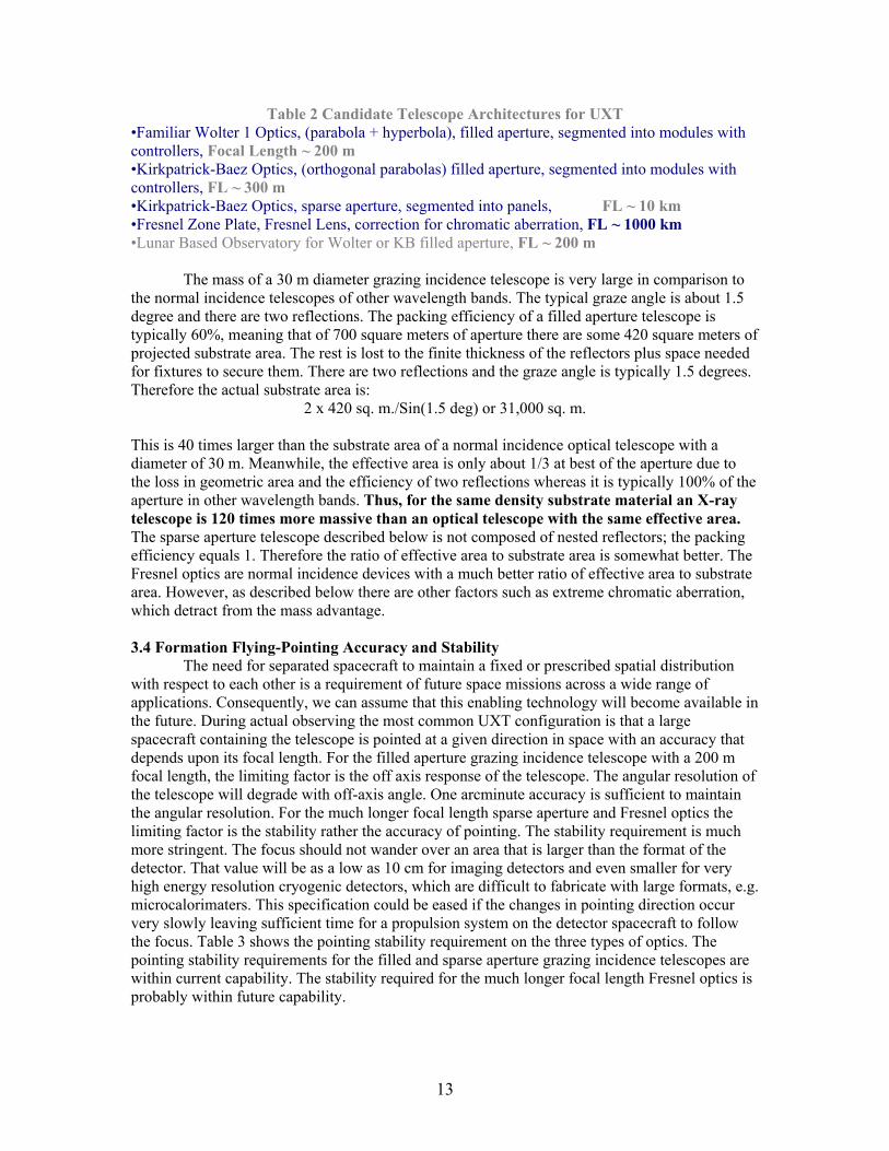
Table 2 Candidate Telescope Architectures for UXT •Familiar Wolter 1 Optics, (parabola + hyperbola), filled aperture, segmented into modules with controllers, Focal Length ~ 200 m •Kirkpatrick-Baez Optics, (orthogonal parabolas) filled aperture, segmented into modules with controllers, FL ~ 300 m •Kirkpatrick-Baez Optics, sparse aperture, segmented into panels, FL ~ 10 km •Fresnel Zone Plate, Fresnel Lens, correction for chromatic aberration, FL ~ 1000 km •Lunar Based Observatory for Wolter or KB filled aperture, FL ~ 200 m The mass of a 30 m diameter grazing incidence telescope is very large in comparison to the normal incidence telescopes of other wavelength bands. The typical graze angle is about 1.5 degree and there are two reflections. The packing efficiency of a filled aperture telescope is typically 60%, meaning that of 700 square meters of aperture there are some 420 square meters of projected substrate area. The rest is lost to the finite thickness of the reflectors plus space needed for fixtures to secure them. There are two reflections and the graze angle is typically 1.5 degrees. Therefore the actual substrate area is:
2 x 420 sq. m./Sin(1.5 deg) or 31,000 sq. m. This is 40 times larger than the substrate area of a normal incidence optical telescope with a diameter of 30 m. Meanwhile, the effective area is only about 1/3 at best of the aperture due to the loss in geometric area and the efficiency of two reflections whereas it is typically 100% of the aperture in other wavelength bands. Thus, for the same density substrate material an X-ray telescope is 120 times more massive than an optical telescope with the same effective area. The sparse aperture telescope described below is not composed of nested reflectors; the packing efficiency equals 1. Therefore the ratio of effective area to substrate area is somewhat better. The Fresnel optics are normal incidence devices with a much better ratio of effective area to substrate area. However, as described below there are other factors such as extreme chromatic aberration, which detract from the mass advantage. 3.4 Formation Flying-Pointing Accuracy and Stability
The need for separated spacecraft to maintain a fixed or prescribed spatial distribution with respect to each other is a requirement of future space missions across a wide range of applications. Consequently, we can assume that this enabling technology will become available in the future. During actual observing the most common UXT configuration is that a large spacecraft containing the telescope is pointed at a given direction in space with an accuracy that depends upon its focal length. For the filled aperture grazing incidence telescope with a 200 m focal length, the limiting factor is the off axis response of the telescope. The angular resolution of the telescope will degrade with off-axis angle. One arcminute accuracy is sufficient to maintain the angular resolution. For the much longer focal length sparse aperture and Fresnel optics the limiting factor is the stability rather the accuracy of pointing. The stability requirement is much more stringent. The focus should not wander over an area that is larger than the format of the detector. That value will be as a low as 10 cm for imaging detectors and even smaller for very high energy resolution cryogenic detectors, which are difficult to fabricate with large formats, e.g. microcalorimaters. This specification could be eased if the changes in pointing direction occur very slowly leaving sufficient time for a propulsion system on the detector spacecraft to follow the focus. Table 3 shows the pointing stability requirement on the three types of optics. The pointing stability requirements for the filled and sparse aperture grazing incidence telescopes are within current capability. The stability required for the much longer focal length Fresnel optics is probably within future capability.

14
Table 3. Pointing Requirements for Maintaining the Focus Within +/- 5cm Box or Within +/- 1 arcmin Off Axis
Optic Type Focal Length Pointing Stability Requirement Filled Aperture
200 m
1 Arcminute (Accuracy and Stability)
Sparse Aperture
10 km
1 Arcsecond
Fresnel Zone Plate/Lens
1000 km
10 Miliarcseconds
3.5 Detector Spacecraft:Traffic Management
The X-ray detector is aboard a much smaller spacecraft. It situated at the focus of the telescope and is pointed in the same direction as the telescope but with an accuracy that need be only be about only one-degree. There may be several other detector spacecraft in waiting to be placed at the focus for observing at a later time. One of these may be stationed rather close to the active detector in order to take over its role during and only during target changes. They must be at a safe distance from the telescope, from the active detector and from each other. Usually when one of the other detectors exchanges roles with the active detector it will be according to a schedule. However, there will be unexpected transient events, such as a supernova, nova, or gamma-ray burst that take over priority over the schedule and may require that one of the detectors in waiting to be at the focus as soon as possible.
Finally there are other detectors that are no longer in use because of failure, obsolescence or they have exhausted an essential consumable material. They must be safely disposed of perhaps by removal to large distance. There could be a dozen or more detector spacecraft in all. Formation flying has to include traffic management of all four classes of spacecraft: the large telescope, the active detector at the focus, the constellation of detectors standing by , and the detectors that are no longer functioning.
The responsibility for maintaining the proper spatial relation between the telescope and the detector , i.e. act as a virtual optical bench , should be upon the much smaller, more mobile detector spacecraft. For target changes the telescope would simply rotate while the detector displaces its position by the amount and in the direction needed to take up the new focus station and then point at the new target. This study has not altered that view. The detector spacecraft are much less massive and much more maneuverable than the telescope. They can replaced in case of a failure or obsolescence by the launch and rendezvous of a new detector spacecraft equipped with a full load of propellant for maneuvers and attitude control. (From time to time the telescope spacecraft will be re-supplied with propellant, which it needs for attitude control and stabilizing its position against perturbations.) The telescope spacecraft would play only a passive role in the alignment process. It would display markers, and transmit or reflect back signals to the detector spacecraft.
The most common configuration consists of the telescope engaged in formation flying with a single detector spacecraft. With the appropriate choice of instrument for the task this configuration seems capable of performing many of the important measurements now identified. However, depending upon what is required for very high-resolution spectroscopy there may be some measurements that can only be performed with dispersive gratings or crystals. In that case two detector spacecraft may be required to engage in formation flying with the telescope. One has the dispersive element, the other, the actual detector. Because of the large spatial scale and

15
spreading of the dispersed X-ray beams it will be possible to measure only a small wavelength interval at a time by this method. However, that may be sufficient given that the non-dispersive cryogenic spectrometers of the future, i.e. microcalorimeters and superconducting tunnel junction devices will be capable of performing moderately high resolution spectroscopy over a very broad band and leave only small wavelength intervals where there is a need for very high resolution to resolve lines or measure their wavelength profile. 3.6 Formation Flying Accuracy
The accuracy that the UXT requires for formation flying is determined by factors, (1) the depth of focus of the telescope, (2) the format or field of view of the detector, (3) the accuracy with which the mirror can be pointed and its pointing stability. All three factors also involve the focal length. The required accuracy is not the same for all measurements but the system has to be capable of satisfying the most stringent requirements. Operating at less than maximum accuracy when permissible may reduce the level of propellant consumption by the telescope’s attitude control system and thereby the frequency of missions to re-supply it.
We define the distance out of the focal plane that results in the beam spread being equivalent to one arc second angular resolution as the depth of focus. For a focal length of 200 m the focal plane scale is 1 mm equals one arc second. With a telescope diameter of 30 m the 1 arc second depth of focus is 6.7 mm. The tolerance in the axial distance between the telescope and the active detector should then be about a third of that or 2 mm for the 200 m focal length and larger for longer focal length. Some detector spacecraft will be able to fine adjust the position of the detector with respect to the focus by an internal mechanism that positions the detector several centimeters fore and aft. This would reduce the demands upon the thrusters of the propulsion system and allows it to be optimized for position control over a larger scale. The error tolerances along the two perpendicular axes are limited by the size of the smallest format detector. That would the high resolution non-dispersive spectrometers such as the microcalorimer being developed for Con-X (Kelley et al,(5), Silver et al.(6)) or the superconducting tunnel junction (STJ) (Martin et al, 2000(7)) arrays that are under development at ESTEC. The current size of the microcalorimeter array is 6 mm. That would cover only a 6 arc second field in the UXT focal plane (assuming a focal length of 200 m). An STJ array is even smaller. A 100 x 100 array of 10 x 10 micron detectors which is still in the future is only 1 mm x 1 mm. We assume that they can grow to 10 mm x 10 mm, which is an array of one million pixels. Taking the same criterion as above that the tolerance is 1/3 of the total margin the perpendicular positional tolerance is +/- 5/3 mm or 1.67 mm.
In summary the tolerances on formation flying accuracy are about +/- 2 mm in the axial direction and +/- 1.5 mm in the two perpendicular directions. The responsibility of satisfying these requirements is placed upon the detector spacecraft. We assume that the telescope satisfies the pointing accuracy and stability specifications listed in Table 3. The pointing stability limits are needed to insure that the detector spacecraft is able to react quickly enough to jitter in the pointing direction to keep the focus on the detector. As in all X-ray astronomy measurements we detect one photon at a time and are able to determine its celestial coordinates with the use of high precision aspects sensors. Therefore jittering of the image is not a factor.

16
Figure 6. Formation flying architecture for UXT containing filled aperture Wolter Type 1 X-ray telescope, before a target change (upper section) and after (lower).

17
3.6 Changing Pointing Direction To change pointing direction the telescope rotates about its axes. The celestial motion
may be rather indirect in order to obey solar avoidance and other constraints. The angular acceleration and deceleration of a change in targets could cause oscillations in the telescope. This could be particularly troublesome with unsupported membrane telescopes (Sect. 5). The design of the telescope structure would take cognizance of this phenomenon and provide stiffness or damping to minimize oscillations.
While the telescope is changing attitude the detector that will be observing at the new target navigates under its own power to the new focus. That detector may be the same as the one employed for the measurement that has just ended or a different detector from the group that had been standing by for a new type of measurement. The sequence of motions is acceleration, coasting, and deceleration. It is likely to include intermediate changes in its celestial pointing direction to align the thrusters along the desired direction for acceleration Target changes may or may not include a change of detector. The telescope and detector configurations are shown both before and after target changes in Fig. 6.
X-ray Sky Scan Survey If the time required for changing targets is of the order of an hour or more then over the ten-year or longer life of the observatory a total of several thousand hours may be spent changing targets. This large quantity of time should be put to good use. If UXT consists of the shorter focal length telescopes like the 200 m Wolter Type 1 an excellent use of the changing time is performing an X-ray sky survey during the scan from initial to final target. This technique would be similar to the “Slew Survey” of the Einstein Observatory, 1978-1981 (Elvis et al. 1992(8)). The optimum detector for these scans is a wide field imager. The detector remains at the focus by moving and changing attitude in synchronism with the telescope’s rotation to a new pointing direction. That is it scans a strip of sky equal to the length of the slew from the old target to the new target in one dimension and the field of field of view of the detector in the other. If the detector has a field of view of 10 arc minutes then a target change of 90 degrees would cover 15 square degrees of sky. (With the longer focal length sparse aperture and Fresnel telescopes the detector field of view will be too small to utilize the time in this way.) The detector spacecraft for the sky survey during target changes will have to a more capable propulsion system than the others because only it has to follow along with the focus. If another spacecraft is to take up the new focus it may be able to take a more efficient route with respect to propellant.
The ROSAT All Sky Survey (9) is currently and indefinitely into future the most sensitive X-ray survey of a large region of the sky. We estimate that with a 10 arc minute by 10 arc minute field of view detector a single UXT slew of 90 degrees over the course of one hour would be 25 times more sensitive than the RASS within the 90 deg. x 1/6 deg. region that it covers. The sensitivity will increase almost linearly with the field of view. (We are in the regime between photon limited measurements where the sensitivity is proportional to the time spent on a target and the background limited regime where the sensitivity varies as the square root of the time.) For source detection and positioning the detector could be a simple technology, low cost device such as a gas proportional counter whose area can easily exceed a square meter. At a focal length of 200 meters the field of a one-meter format detector would be 16 arc minutes. New, low cost position sensitive solid state devices with much better energy resolution are available in small formats. In principle they can be arrayed to form one meter formats. One of the advantages of UXT’s formation flying architecture is that this detector, like any other detector does not have to be delivered according to a rigid schedule. It can be introduced at any time by launching a spacecraft that is capable of performing a rendezvous with the observatory.

18
4 The X-ray Optics 4.1 Requirements of UXT Table 4 lists our requirements on the performance of the X-ray telescope for UXT.
Table 4 Telescope Performance Properties Property Requirement Effective Area 250 square meters at 1.5 keV Angular Resolution 1 arc second HPW or better on axis Field of View 5 arc minutes FWHM Pointing Accuracy and Stability Focal length dependent, see Table 3 Maximum Time for Target Change of 60 degrees
2 hours
Lifetime 15 years or longer Cost Not to exceed cost of other major X-ray
Observatories such as Chandra Architecture Single focus telescope
Modular construction Controllers for in situ alignment of
modules to common focus Not dependent upon the success of a single
launch Able to function without all modules
present Engages in formation flying with detector Accommodates multiple detectors
The performance of the optics should satisfy the effective area and resolution specifications as much and as possible of the others in the above table. There is no explicit specification on the maximum mass, volume or cost of the telescope. However, limits upon these quantities are always implicit and dependent upon the resources that will be available to the program at the time of development.
The performance requirements do not place any constraints upon the design of the optics. In particular the formation flying architecture permits very long focal lengths that are well beyond anything ever considered for conventional spacecraft architectures. We studied several different optical designs: two filled aperture geometries, a sparse aperture optic, and a Fresnel system. The optical design of telescopes of every X-ray astronomy mission this far and for the future Con-X is the filled aperture Wolter type 1 or a double conical approximation. With some innovations including segmenting the telescope into controllable modules and employing lower mass materials we would have to consider this familiar design as the early front runner for UXT. 4.2 Filled Aperture Telescopes: Wolter Type 1 and Kirkpatrick-Baez Designs
There are two optical designs for a filled aperture telescope, the classical Wolter Type 1 geometry, i.e. parabola plus hyperbola of revolution, and the Kirkpatrick-Baez (K-B) geometry. The K-B consists of orthogonal one-dimensional parabolas. The K-B design is in fact older but it has been in space only during several brief sounding rocket flights. A prototype K-B mirror was constructed for the LAMAR telescope, a former program to provide an “Attached Payload” to the

19
International Space Station. However the LAMAR program as well as all other “Attached Payloads” were cancelled when the ISS suffered delays. The ASCA and BeppoSAX X-ray telescopes have actually been double cones rather than a true Wolter 1 parabola plus hyperbola. The theoretical angular resolution of double cones is inferior to a true Wolter 1 optic. However, the difference was inconsequential in those cases because the telescope resolution was limited by other factors. That will not be true of UXT. Sketches of modular Wolter and K-B telescopes are shown in Fig. 7 and Fig 8. Figure 7. Left panel, the Wolter Type 1 design consisting of front parabola of revolution and rear hyperbola of revolution. It is the yellow curve in a color reproduction., The right panel is a nested set of Wolter Type 1 shells, in fact one of the three X-ray telescopes of XMM-Newton.
Figure 8. The Kirkpatrick-Baez geometry of orthogonal one dimensional parabolas. The right hand panel shows a nested system of reflectors. It is a prototype K-B telescope developed for the LAMAR telescope of the International Space Station’s “Attached Payloads” program. That program was subsequently cancelled following severe delays in the schedule of the ISS.

20
The Wolter design has been preferred for several reasons. One, its theoretical imaging properties are superior to the K-B both on and off axis. The true orthogonal parabola K-B system suffers from an aberration in the image formed by the front set of parabolas. Parallel rays that would travel the same distance to form a line focus when the rear mirror set is absent are now reflected to travel along different path lengths to the focal plane to a point focus when the rear set of reflectors is in place. Therefore for the front dimension the rays no longer intersect the optic axis at the same distance from the entrance plane. That is the image is blurred in one dimension. Two, the Wolter geometry is more efficient, geometrically, particularly at the smaller graze angles which focus higher energy X-rays. The effective area of the Wolter system is diminished by the finite thickness of only the front reflectors. In the K-B system both the front and rear set of substrates reduce the area. The effect is quite significant at higher energies. Three, the focal length of a K-B system is nearly twice that of a Wolter system of equal area and bandwidth. In the conventional mission architecture, shorter focal length is usually preferable because the system is more compact and a detector covers a larger field. Four, the highest angular resolution telescopes ever constructed, namely the Chandra X-ray Observatory and ROSAT are complete cylinders of revolution, an inherently strong structure that can conform to the ideal figure more faithfully than partial or segmented cylinders. The reflectors of the K-B system are quasi flat plates, a much weaker figure than a complete cylinder of revolution. Table 5 lists the calculated effective areas of both Wolter Type 1 (or any double conical geometry) and K-B mirrors for several possible focal lengths of UXT. The Wolter system is shorter, more efficient and its area to mass ratio is superior to the K-B by fifty per cent.
Table 5. Effective Area and Mass of UXT For Several Telescopes of Varying Focal Length
Wolter Type 1 Kirkpatrick-Baez Focal Length(m) 300 200 180 300 250 200 Area sq. cm. (1 keV) 5.4E6 4.8E6 4.6E6 5.8E6 5.4E6 4.8E6 Area (5 keV) 3.8E6 2.0E6 1.66E6 1.8E6 1.2E6 7.8E5 Mass (tons)3 244 178 161 375 318 258 Area(1 keV)/Mass 2.2E4 2.7E4 2.9E4 1.6E4 1.7E4 1.9E4 1 We assume that all the reflectors are made of glass 300 microns thick and that the reflector mass is multiplied by a factor of 1.6, to allow additional mass for the mirror structure. The coating is gold. However, in this new application with much larger dimensions and a formation flying mission architecture the Wolter system enjoys fewer advantages. There are no longer any physical limitations on the focal length to constrict the K-B telescope. Therefore, we are free to make the focal length of a KB optic twice that of a Wolter optic. The large dimensions of UXT do not permit a Wolter substrate to be a complete cylinder of revolution. The telescope must be
21
segmented into modules. Therefore, it no longer has the inherently superior strength of a closed cylinder. In fact, the reflectors at the largest radii are only slightly curved and are similar to the quasi flats of the K-B system with respect to stiffness. With segmentation the aberration in the imaging properties of the K-B system can be rectified. By dividing a parabolic reflector of the front set into many independent segments we are free to optimize the figure of each piece by adjusting its focal length to place the image precisely on the focal plane. With the piecewise adjustments the reflector as a whole is no longer a perfect parabola but that is rather inconsequential because it does not make fabrication or alignment any more difficult. The double conical telescope still has the advantage of providing more effective area at higher energies and somewhat superior resolution off axis. There is an aspect of the imaging properties where the KB optic is superior to the Wolter. In reality the surfaces of all reflectors contain defects, e.g. pits and scratches that cause large changes the slope locally. The result is a scattering halo around the image. Because the defects exist on only on a small fraction of the surface area it is unlikely that both reflections will be affected. For the KB telescope a defect will affect only one dimension. In the other dimension the ray is most likely follow the proper trajectory. Consequently most of the scattered X-rays are confine+d along the two axes. On the other hand in a cylindrical geometry like the Wolter the second reflection is in the same plane as the first. The scattered X-rays will appear at all azimuth angles resulting in a uniform halo surrounding the image formed by the focused rays. That is, while a K-B telescope has the same number of scattered rays as the Wolter they are confined to a much smaller region of the focal plane.
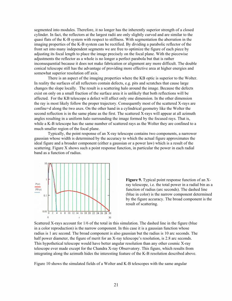
Typically, the point response of an X-ray telescope contains two components, a narrower gaussian whose width is determined by the accuracy to which the actual figure approximates the ideal figure and a broader component (either a gaussian or a power law) which is a result of the scattering. Figure X shows such a point response function, in particular the power in each radial band as a function of radius.
Scattered X-rays account for 1/6 of the total in this simulation. The dashed line in the figure (blue in a color reproduction) is the narrow component. In this case it is a gaussian function whose radius is 1 arc second. The broad component is also gaussian but the radius is 10 arc seconds. The half power diameter, the figure of merit for an X-ray telescope’s resolution, is 2.8 arc seconds. This hypothetical telescope would have better angular resolution than any other cosmic X-ray telescope ever made except for the Chandra X-ray Observatory. This figure, which results from integrating along the azimuth hides the interesting feature of the K-B resolution described above. Figure 10 shows the simulated fields of a Wolter and K-B telescopes with the same angular
Figure 9. Typical point response function of an X-ray telescope, i.e. the total power in a radial bin as a function of radius (arc seconds). The dashed line (blue in color) is the narrow component determined by the figure accuracy. The broad component is the result of scattering.

22
resolution. Both fields contain two point sources, one with only 1/2 % of the strength of the other. The fainter source is offset from the first by 10 arc seconds at angle of 45 degrees in the first quadrant resolution. Both fields contain two point sources, one with only 1/2 % of the strength of the other. The fainter source is offset from the first by 10 arc seconds at angle of 45 degrees in the first quadrant.
Figure 10. Simulated fields of Wolter (left panel) and K-B telescopes with same angular resolution, 3 arc seconds half power diameter. Both contain two sources. One is Y2 % of the intensity of the other and is displaced 10 arc seconds off at 45 degrees to the horizontal and vertical axes in the first quadrant. The scales are in arc seconds. The fainter source is visible in the K-B field but lost in the scattering halo of the stronger source in the Wolter field, at least in the original figure if not in reproduction. This means that the K-B telescope has more sensitivity for detecting faint sources in the vicinity of strong sources and detecting faint features of extended sources with an intense point source at the center. An important objective, which requires detecting faint sources close to strong sources is the study of gravitationally lensed multiple images of a quasar. Important examples of detecting faint extended features around strong point sources include the study of jets in active galactic nuclei and the study of host galaxies of quasars. 4.3 Fabrication of KB and Wolter Optics Wolter Mirror There is a considerable body of experience in the fabrication of Wolter optics. All X-ray astronomy missions have employed Wolter telescopes. The most relevant programs are XMM-Newton, the Constellation X-ray Mission, and XEUS, all of which employ high throughput telescopes with good angular resolution. The substrates for these telescopes have been or will be produced from mandrels made in the inverse figure by epoxy replication or by electroforming nickel. Studies of replicated segmented Wolter substrates are currently being carried out by both NASA and ESA. Figure X+2 shows some electroformed substrates that have been produced for ESA. Epoxy replication upon thin glass substrates results in a much lighter mirror than nickel so that process has become the baseline approach for the Spectroscopy X-Ray Telescopes of Con-X. We can expect that the most advanced technology for fabricating light weight segmented mirrors will emerge from these NASA and ESA studies. However, because UXT’s telescope is so much larger and requires much better angular resolution than Con-X’s goal it is not clear that these studies will result in a process that can be used for UXT.

23
Figure 11. Segmented Wolter 1 mirror shell substrates made by Media Lario (Italy) for ESA’s XEUS program. These substrates are electroformed nickel like XMM-Newton reflectors. The gold coating serves both as a release agent from the mandrel and as the X-ray reflector surface. Kirkpatrick-Baez Mirror There is much less experience manufacturing K-B telescopes and in contrast to the Con-X and XEUS studies of a segmented Wolter 1 telescope no research is being carried out. Nevertheless, UXT’s size and architecture are so vastly different than the programs that will proceed it that we cannot dismiss the KB geometry as an option that may be better adapted. A sketch of a nested KB mirror system is shown in Fig. X+3. One of the main virtues of the K-B mirror system is how easily it can be segmented into modules of nearly equal size at least conceptually. This is shown in Fig. X+4.
Figure 12. A Kirkpatrick-Baez mirror system consisting of two orthogonal stacks of one dimensional reflectors which are quasi parabolas.

24
Figure 13. Front View of K-B mirror systems. As shown in the right panel the K-B mirror can be segmented into equal size modules. Each reflector is a parabola of rather small curvature. One of the virtues of the K-B system is that each reflector can itself be subdivided into units with even less curvature. This is shown in Fig. X+ 5, which illustrates a parabolic reflector divided along the optic axis into sub-segments of several different sizes with each sub-segment faced off in a slightly different direction. When the number of sub-segments is sufficient they can be flats, which would reduce the difficulty of fabrication. The number varies with distance from the optic; there is a small number for reflectors close and a large number for reflectors at the extremes. They need only be flat in one dimension. However, it is not clear that there exists a manufacturing process than can benefit from that feature. The comparative practical merits of the Wolter and KB geometries are shown in Table 6.
Figure 14. A one-dimensional parabolic reflector is divided several different ways into smaller units along the direction of the optic axis.

25
Table 6. Comparison of Wolter 1 and K-B Optics
Wolter 1 (double conical) K-B (orthogonal plates)
• Larger aperture efficiency especially at higher energies
• Can be segmented into modules of equal size and shape
• Better angular resolution in theory • Segmentation of a reflector and optimizing focal length of each segment can correct an aberration present in ideal parabolas
• Scattering halo is confined along axes allowing higher sensitivity in the vicinity of strong point sources to search for jets and other features
• Requires curved substrates • Can use flats but will benefit from curvature
• Alignment of parabola to hyperbola is critical
• Front to rear alignment not critical
• Requires mandrels, as many as one for each radial position
• None or very few mandrels needed
• Constancy of radius of curvature important • Can tolerate non-planarity as long as slope is correct along direction of optic axis
• Some substrates interchangeable • More substrates interchangeable Artist drawings of large, modular KB and Wolter telescopes (XEUS telescope) are shown in Fig. X+3. Important systems like solar energy panels, attitude control systems, etc. are not shown. The modules of the KB mirror are squares, all with the same dimensions, while those of the Wolter are subdivided pie sectors of several different sizes with many of each size.
Figure 15. Large modular square KB telescope (left) and Wolter Type 1. The Wolter mirror is actually an artist’s conception of the XEUS telescope that ESA plans to develop.

26
4.4 Sparse Aperture Telescopes Extreme Sparse Aperture KB The formation flying architecture’s lack of restriction upon the focal length offers X-ray telescopes design options that are unavailable in missions with conventional architecture. One of these is what we define as the “sparse aperture” geometry where the focal length is much longer than the conventional filled aperture telescope’s and the telescope occupies only a fraction of the potential total aperture. The sparse aperture geometry offers two important advantages. One, more space is available for structure and figure control mechanisms between adjacent substrates The space may be crucial if adaptive optics are needed to satisfy the resolution goal of one arcsecond. Two, the substrates have much less curvature, and for the KB geometry substrates larger than one meter can be flats. In the most extreme version of the concept a single shell from a nested Wolter telescope (or a single pair of orthogonal parabolas from a KB system) is scaled up in size to where its effective area is equal to that of the original filled aperture telescope. For example the middle shell from the XMM set of 58 shells, would be scaled up about a factor 8 and the resultant shell would have about the same effective area as the entire original telescope and a focal length 8 times larger. The effective area as a function of energy would be narrower because the range of graze angles is smaller but one could select the shell where the value of the high-energy cutoff is acceptable.
A KB optic may benefit more from sparse aperture geometry than the Wolter. The reason is that when scaled up sufficiently a series of flat substrates whose size is a meter and whose angular orientations are correct can approximate a parabola to better than 1 arcsecond accuracy. Flat substrates are highly desirable. A flat is easiest to fabricate. The figure of a flat membrane under tension would be stable even if the tension varies. All substrates are identical and nterchangeable. This makes achieving 1 arcsecond or better angular resolution more feasible. An extreme sparse aperture KB telescope is shown in Fig.16. When viewed from the perspective of incoming rays the aperture looks like a square. For the aperture to equal 30 m x 30 m the size of each panel normal to the incoming rays is 30 m and the longer dimension along the optic axis, assuming the average graze angle is 1.0 degrees, is 1.1 km in length. The focal length should be at least ten times larger than the length of the reflector or about 11 km for good off-axis resolution.
Figure 16. Sparse aperture K-B telescope made of a matrix of flat panels. Each panel is oriented such that the figure of the total surface approximates the ideal surface, which is not quite a parabola.

27
We can fabricate flat substrates from tensioned membranes with the same technology that the Steward Observatory (Woolf, 1999) has proposed for the Terrestrial Planter Finder mission. However, we have two additional obstacles to overcome. One, as explained above, the total substrate area of a grazing incidence telescope is much larger than an optical telescope with the same aperture. Two, the substrates must be much smoother on a nanoscale in order to reflect X-rays efficiently.
The sparse aperture KB telescope has a much higher geometric efficiency than the filled aperture KB telescope. In the case of the latter nested reflectors with finite thickness consume about 50% of the aperture. On the other hand space at the rear face of each reflector panel of a sparse aperture optic is not constrained. The rear can accommodate support structures or mechanisms to form the figure that would be prohibitively large for a nested system. For example there is space to employ a mechanism similar to the one described by Woolf, et al for applying tension to a membrane reflector or fine tuning a curve with local electrostatic forces. Or the frame supporting the tension could be a low density but bulky material such as silicon carbide foam, or a lightweight Buckminster Fuller type network of thin rods. The result would be a thick frame with stiffness equal to a heavier thin frame. These options are not available to a filled aperture mirror system because there is too much loss of efficiency with an aperture devouring thick structure between adjacent substrates.
On the other hand there are several problems associated with this sparse aperture telescope. In particular, the focal length is very long. For a 10 kilometer focal length coverage of a 5 arc minute field requires a detector whose size is 15 meters square. This is too demanding of a position sensitive detector especially of a solid state device with good energy resolution. Consequently it will not be possible to have a significant field of view. We require better pointing stability of a long focal length telescopes to keep the source on the detector. An error of 5 arc
.
3
Figure 17. Deployment of UXT in phases by building up area of telescope in situ. The top portion represents a filled aperture telescope, the Wolter Type 1 mirror assembly. The lower, phases in the in situ growth of a sparse aperture Kirkpatrick-Baez telescope. The two telescopes are drawn to different scales. Spacecraft and various other systems are not shown.

28
seconds would displace the image by 12.5 centimeters. Cryogenic detectors with very high energy resolution, key instruments in any future mission, cannot be made in large enough formats
Also, the sparse aperture telescope seems to be much less compatible with developing UXT in phases. Phased development is a necessity in order to spread the cost over time and we wish to gain experience constructing, deploying, and operating the observatory during its early phases where accommodations can be made. Perhaps because of its unfamiliarity it is more difficult to imagine how the sparse aperture telescope would be deployed in phases. In contrast how the much more compact filled aperture telescope would be deployed in phases is much easier to imagine. More mirror modules would be launched and attached to the array at the site and the solar array is enlarged and repositioned while the spacecraft remains situated at the center. Indeed, ESA proposes a similar procedure for the evolution of XEUS from stage 1 to stage 2. The various functions normally performed by a spacecraft such as attitude control, thermal control, and communication would have to be exercised at the rear of the sparse array or adapted to the odd architecture in some other mode. Three, the panels that comprise the telescope are quite long, about 1 km for each of the two. Consequently the moment of inertia is very large. There will have to be thrusters at several locations. Changing the pointing direction may require a particularly long time. Finally, because the area of the panels is so large solar radiation pressure is significant. It will affect the stability of the observatory site. The point at which all forces come into balance will depend on the angle of the panels with respect to the sun and hence the pointing direction. It is not clear how much of a problem this will be. UXT may already be in continuous motion depending on its site.
Moderate Sparse Aperture KB
There is a less extreme version of the sparse aperture telescope. As an alternative to scaling up a single pair of reflectors to the point where their effective area is equal to that of the filled aperture telescope, we can scale up a single front-rear module pair of nested reflectors (or a group of any number of modules). The geometry is shown in Fig. 18.
Figure 18. A less extreme version of the sparse aperture telescope is shown. The aperture of a single front-rear module pair of KB reflectors is scaled up to a size of about 25m x 25m with an effective area of 3 million square centimeters. This telescope would be composed of modules whose frontal dimensions would be about the same as those of the original filled aperture telescope. The difference is that the sparse aperture telescope is a two dimensional array of modules whereas the moderate sparse aperture telescope is a three dimensional array with the third dimension along the optic axis. Each substrate is divided into sections that are in series within the modules along the optic axis. In effect the substrates are longer than those of the filled aperture telescope by the scale factor. This configuration has a much larger number of modules than the filled aperture telescope but each module contains many fewer substrates. Consequently the volume of the sparse mirror array is larger than the filled aperture mirror by the scale factor but the masses of the two are the same.

29
This configuration offers considerably more space for figure control structure and adaptive optics mechanisms than the filled aperture telescope. However, unlike the extreme sparse aperture telescope described above the space behind the reflector is not unlimited. The criterion for the minimum focal length and thereby the scale factor is that the contribution of a 1m section of the substrate to the angular resolution should be less than one arcsecond. The scale factor is about 25 in that case. 4.5 Fresnel Optics Introduction Fresnel optics, zone plates and telescopes in particular are a radically different type of optic than the grazing incidence telescope. While small devices are operating routinely at synchrotron radiation facilities they have rarely been considered for X-ray astronomy, not withstanding a paper on the subject by Dewey, Schattenburg, and Markert, 1996. The necessity for extremely long focal lengths has precluded their use in X-ray astronomy up to now. However with formation flying as the basis for UXT there is in principle at certain sites no limit upon the focal length. The advantage of Fresnel optics is two fold. One, they are normal incidence devices. The significance is that the total substrate area is equal to the aperture, not nearly 100 times the aperture like a grazing incidence telescope. Two, they operate in transmission not reflection. Consequently the figure of the optic is much less critical. In transmission geometry we can tolerate non-planarity to a considerable extent and are hardly sensitive to surface roughness. Therefore, there is no need to have a perfect figure or polish the optics. Not only is the time and cost of polishing avoided but the optic does not require the stiffness and strength of one that maintains a precise figure. Normal incidence and transmission conspire to allow the mass of the optic to be 2 or 3 orders of magnitude less than a grazing incidence telescope whose mass is shown in Table 5. That is the mass of the optic is one ton or less as compared to several hundred tons. The low mass of Fresnel optics changes the cost picture and the development schedule radically. With clever packing, perhaps similar to a double folding umbrella or a Chinese steamer the entire optic can be deployed with a single launch with a vehicle from the current stable of rockets. Throughout the following discussion concerning the throughput and angular resolution of Fresnel optics we are assuming that the Fresnel zones all have the ideal size, shape, and spacing. That is, no errors are made in establishing the zones across the full diameter. We have not yet performed the simulations needed to understand how the throughput and angular resolution are affected by errors. With Fresnel zones of large size, i.e. ~ 1 mm that require extremely long focal it is likely that errors will be relatively small. Very Long Focal Lengths
While the relatively low launch costs may seem attractive there are downsides to Fresnel optics. One is the necessity for an extremely long focal length. We consider the zone plate, a staple of an introductory course in electricity and magnetism, which consists of concentric bands that are alternately open and opaque as shown in Fig. X+ 7. It acts

30
as a converging lens with the main focus on the central axis containing about 25% of the incident flux at each wavelength, which is not much less than the efficiency of a grazing incidence telescope. The focal length, F, is given by the following approximate expression, where D is the diameter, d is the distance between bands (assumed to be constant) and λ is the wavelength.
F dD2λ
⋅=
The focal length is highly dependent upon the magnitude of d. For D = 30 m, d = 1 mm microns, and λ = 10 Angstroms, F = 15000 km. For d = 1 micron, F = 30 km. There are two extreme values of d to consider. One is a large value like 1 mm which results in a very long focal length. In this case the zones can be made across the entire area by precision machining. It should be possible to construct the zones in segments and align the segments with sufficient precision. The opposite approach is to make the size of the zones small, e.g. 1 micron. This reduces the focal length to a much more convenient value of 30 km. However, this would require lithography and maintaining coherence between zones over the entire 30 m diameter. This seems to be a very formidable problem Extreme Chromatic Aberration
An even more challenging problem is severe chromatic aberration. The focal length is directly proportional to the X-ray energy. Unless there is a strong line in the source’s spectrum there is not much intensity at any point along the optic axis. We consider a 30 m diameter zone plate and a 1 m detector at the focus of 10 Angstrom (1200 eV) X-rays at a distance of 30,000. The effective area of the zone plate, A is:
Aπ 302
⋅
40.25⋅= A 176.715= cm2
The bandwidth is 1/30 of 1200 eV or 40 eV. In comparison, the Chandra X-ray Observatory has a bandwidth of about 2000 eV (most of the photons of typical source < 2000 eV) an effective area
AChandra 1= m2
Figure 19. Fresnel zone plate consisting of alternating open and opaque zones.

31
Throughput RatioA 40⋅
AChandra 2000⋅= Ratio 3.534=
The photon collection is several times that of Chandra but not yet a remarkable increase. Field of View and Angular Resolution If the size, shape, and spacing of the Fresnel zones are constructed with precision the angular resolution is potentially very high. However, without correction for chromatic aberration there is a large loss in throughput. The field of view, FOV is estimated below.
d 10 3− m:= λ 10 9− m:= r 15m:= Fd r⋅λ
:= F 1.5 107× m=
FOV1mF
:= FOV1mF
:= FOV 6.667 10 8−×= radians or 0.014 arsec
The FOV is quite small but is large enough to study features that the Chandra telescope cannot resolve such as nuclear jets. The angular resolution, AngRes, depends upon the energy resolution, EnRes, which we assume to be 2 eV:
AngResEnRes40eV
FOV⋅= AngRes 3.438 10 4−×= arcsec
This would be a large improvement upon the Chandra X-Ray Observatory’s resolution of 0.5 arcsecond. The throughput would be reduced a factor of 20 resulting in it now being only about 1/6 of Chandra but it remain large enough to allow important studies of many extended sources. In this application the virtue of the Fresnel optic is not its throughput but its potentially superior angular resolution for both imaging and dispersive spectroscopy. Resolution of the order of a few hundred microarcseconds would be a useful intermediate phase between Chandra and MAXIM, a potential future mission based upon X-ray interferometry, which is being studied in a program parallel to this one (Cash, 2000). In a later section we describe a technique proposed by L. Van Speybroeck that would increase the throughput for imaging by correcting chromatic aberration in finite size energy bands. Fresnel Telescope The Fresnel telescope is a refractive device. It is similar to the zone plate in that it is divided into zones. However, instead of being alternately completely open and opaque the thickness of the material is precisely sculptured across each band to retard the phase of transmitted X-rays such that all rays with the same energy will interfere constructively at a point along the optic axis to form an image. Chromatic aberration exists for the lens as well but the focal length is proportional to the square of the energy as compared to a linear dependence of the focal length upon energy of the zone plate. Unlike the zone plate there are both converging and diverging forms of the Fresnel lens. The index of refraction of the lens material is less than that of the vacuum. Therefore, contrary to optical lenses a converging lens is concave. Figure X + 8 illustrates a converging Fresnel lens.

32
The unit on the right is the more practical device because there is less material to absorb X-rays. The thickness of each zone is tailored to make parallel coherent rays arrive in phase in order to interfere constructively on the optic axis. That is, the difference in phase change between the thick and thin parts of each zone is precisely equal to the value needed for all rays with the same energy to arrive in phase at the focus. It is possible to magnify the effect by placing multiple lenses in series, which of course results in more X-ray absorption. Fig. X+1 illustrates some small Fresnel X-ray lenses that are used in synchrotron radiation studies. Figure 21. Single and compound refractive Fresnel X-ray lenses, Aachen University Physics Department.
When made of a low absorption number material, e.g. Be, the lens is a more efficient device than the zone plate because all zones transmit. However, this is true only above 2 or 3 keV. Unfortunately, for the study of high z objects, whose spectra are highly redshifted, the band below 2 keV is a critically important region. Therefore, the utility of the Fresnel lens is more limited than the zone plate. There is current work pertaining to the use of lithium as the lens material (Arms et al, 2002). If a lithium lens can be brought into space safely where it will be free from the danger of oxidation (and explosion) the low energy cutoff can perhaps be reduced to1 keV. However, this is still above the energy of important emission and absorption lines.
Figure 20. Converging refractive Fresnel lens. The more complex looking, “alligator” unit on the right is more efficient because there is less material to cause absorption. Frequently, both faces of the alligator lens are sculptured.

33
4.6 Correcting Chromatic Aberration of Fresnel Optics In order for Fresnel X-Ray optics to be useful devices it is necessary to correct or avoid the chromatic aberration. We identify three strategies that can do so. Each is effective in only a small band of wavelength. However, they can be repeated and employed simultaneously at many different stations along the optic axis as often as desired to multiply the number of bands. It will not be possible or practical to cover a very large wavelength band. However, during the era of UXT after Chandra and the Constellation X-Ray mission scientific objectives may become more focused rather than based upon broad exploration. For example it may not be necessary to measure the entire spectrum of a source. Most of the information may come from the study of a few spectral lines in particular. Combining Zone Plate and Lens in Series L. Van Speybroeck proposed this technique. It is based upon the fact that the focal length of the zone plate depends on the first power of the energy while that of the Fresnel lens depends upon the second power. When a converging zone plate and a diverging lens are placed in series the energy dependence of the focal length of the combination contains a region where it is stationary, i.e. the energy dependence vanishes temporarily. The effect is shown in Fig. 22.
Figure 22. A higher energy X-ray beam (blue lines) and a lower energy beam (red) are focused by a series combination of a converging zone plate and a diverging Fresnel lens. The fact that the energy dependence of the zone plate’s action varies linearly with energy while that of the lens varies as the square of the energy allows these two rays of different energy to focus to the same point along the optic axis (Van Speybroeck).
However, we have not explored how large a band can be corrected for chromatic aberration by this method. That will depend on what level of angular resolution we are willing to accept, i.e. the poorer the correction the larger the band. However, there is ample room for improving upon the angular resolution of the Chandra X-ray Observatory with a significantly wide band for greater throughput. A drawback of this technique is that the lens cuts off lower energy X-rays at a value that is too high for many scientific objective. This technique like the others can be applied simultaneously over several energy bands. Figure 23 is an artist’s conception of it being applied at two stations with each covering an energy band. The configuration consists of formation flying among four spacecraft. One to support the zone plate, another to support the Fresnel lens and two with X-ray detectors

34
Figure 23. Correction of chromatic aberration in two energy bands simultaneously by combining Fresnel zone plate with Fresnel lens. This involves formation flying between five spacecraft.
Other combinations are possible. In an analogy to a system described by Falkis and
Morris, 1989 it may be possible to correct chromatic aberration with three zone plates of different focal lengths appropriately stationed at the correct distance with respect to each other. If this configuration is effective it would be possible to correct chromatic aberration in a significant range of bandwidth without paying the price of a rather high low energy cutoff that the zone plate-lens combination entails. However, the three zone plate system would come with a significant loss in throughput. Each zone plate will reduce the intensity by a factor of four. However, only the first zone plate need be large diameter. The other two would operate over a limited range of wavelength much closer to the focus so they could be considerably smaller. This procedure can be applied at multiple stations along the optic axis to correct chromatic aberration in several bands of wavelength simultaneously. We have not explored the three zone plate combination sufficiently well to reach a conclusion about its utility. Non-Imaging Concentrator This strategy is effective only for non-dispersive moderate resolution spectroscopy with a microcalorimeter or a similar device. A moderate resolution grazing incidence telescope or non-imaging concentrator intercepts a portion of the converging beam from a Fresnel zone plate or lens and concentrates it further upon a detector with good pulse height energy resolution. The concentrator is stationed at a position where its aperture equals the diameter of the entire converging beam at the energy of interest. It will also concentrate portions of the higher energy X-rays (which have larger diameter and are less convergent) and lower energy X-rays that are either still converging or diverging from their focus upstream. The concentrator will be most effective if the reflectors reflect on both faces. It may be useful to include a second stage capillary concentrator that will concentrate the beam to a smaller spot size. The concentrators have an efficiency of that is typical of grazing incidence telescopes. The purpose of this procedure is to perform moderate resolution spectroscopy upon a known object. As stated above, this measurement may be performed on one band of the energy spectrum while another instrument or instruments are operating simultaneously in other wavelength bands. Because we do not require

35
be made both low mass and relatively large aperture. It should be possible to make a concentrator with 3 m diameter that focuses about 20% of the total spectrum with good efficiency.
Figure 24. Non-imaging concentrator condensing a portion of the chromatic X-ray beam from a Fresnel optic upon a moderately high energy resolution detector such as a microcalorimeter. A second stage capillary concentrator may be used to reduce the spot size. High Resolution Dispersive Spectroscopy Fresnel optics are inherently wavelength dispersing elements. Unfortunately, the dispersion direction is along the optic axis so we cannot utilize the chromaticity directly. A position sensitive detector can be placed at the focus of any given wavelength but unfocussed rays from other wavelengths will also be present. Nevertheless there is no need to correct for chromatic aberration in dispersive spectroscopy. In fact the spectroscopy configuration for the Fresnel optic is essentially similar to that for a grazing incidence telescope. Whether the dispersing element is a transmission grating, a reflection grating or a crystal its action is
Figure 25. Drawing of the Chandra METG/HETG transmission gratings and their dispersed spectra. The spectra are in the focal plane with the wavelength axis perpendicular to the optic axis. the same, dispersing the image by rotating each wavelength off the optic axis by an angle that is proportional to the wavelength. With the achromatic grazing incidence telescope the locus of the dispersed X-rays lies within a plane that is perpendicular to the optic axis. For a transmission grating, e.g. the Chandra LETG or METG/HETG devices the dispersed rays are along a line. Fig.

36
25 illustrates the action of the Chandra METG/HETG, which is a set of two transmission gratings with different periods that are slightly rotated with respect to each other. The system produces two lines of dispersion each covering a different wavelength range. A position sensitive detector, which is in this case the ACIS CCD’s, is situated along the two lines. With the chromatic Fresnel zone plate replacing the achromatic grazing incidence mirror the difference is that the dispersed spectrum has a component along the optic axis as well as perpendicular to it. However, we can still align a position sensitive detector along the wavelength direction. The rays are not detected at normal incidence but this is inconsequential. This works equally well with a device like the in-plane reflection grating spectrometer of XMM-Newton (RGS) and a conical reflection grating whose axis of dispersion is a circle (Hettrick and Bowyer, 1983). The last, the most complex of the three types, is illustrated in Fig. 26. Spacecraft containing any of these of gratings could be placed at several stations along the optic axis to perform high resolution spectroscopy measurements in several energy bands simultaneously.
Figure 26. Focusing Fresnel zone plate acting in concert with conical diffraction grating. The thin black semi-circle is the locus of the dispersed spectra when the focusing element is an achromatic grazing incidence telescope. It is a circle in the focal plane. When the chromatic zone plate performs the focusing the locus of the spectrum (red semi-circle) is rotated to another plane where detectors are sited. Because of the long focal length it will not be possible to observe the entire dispersed spectrum or even a large portion of it with a single detector. We will have to select wavelength bands of particular interest. Figures 27 and 28 are artist’s conceptions of spectroscopy systems with four spacecraft engaged in formation flying, the zone plate, the dispersing element plus two detectors observing different portions of the spectrum.

37
Figure 27. Fresnel zone plate, reflection grating and two detectors, a total of four spacecraft engaging in formation flying to constitute a dispersive spectroscopy configuration. The locus of the dispersed X-rays forms an arc that is at an angle to the focal plane. The two detector spacecraft may change positions along the arc to cover other wavelength bands.
Figure 28. Same as Fig. 28 except that the dispersive element is a transmission grating system like the Chandra METG/HETG. It consists of two sets with different periods at slightly different angles. Two lines whose color varies with distance from the center represent the dispersed spectra from the transmission grating.

38
Table 7 summarizes the three techniques for rectifying chromatic aberration in Fresnel optics.
Table 7. Three Techniques for Reducing Chromatic Aberration of Fresnel Optics7
Each of the following is effective only in a narrow band of wavelength. However the total bandwidth can be increased by applying each multiple times and
simultaneously at various distances from the telescope. • For Imaging and Source Detection: Combine Convergent Fresnel Zone Plate and Divergent
Fresnel Lens (Van Speybroeck, 2000) or Possibly, Pending Further Study, a Three Element Zone Plate System (Falkis and Morris, 1989)
• For Non-Dispersive Moderate Resolution Spectroscopy (~2 eV) : Non-Imaging Concentrator with Microcalorimeter at the Focus
• For Dispersive High Resolution Spectroscopy (~0.5 eV) : Variable Space Reflection Grating , In-Plane or Out of Plane, Between the Fresnel Zone Plate and Detector
5. Adaptive Optics 5.1 Introduction The most challenging aspect of UXT is constructing a telescope of 20m or larger diameter with angular resolution equal to or better than the Chandra 1.2m diameter telescope and whose mass per unit area is much less. Chandra’s resolution was achieved by highly accurate figuring and polishing of inherently stiff and very massive integral shell substrates. Practical limits on mass preclude this method of figure formation and retention for larger shell diameters. As explained above the only option is to make the substrates from much lighter material, segment the telescope into much smaller units and form the figure under the active control of positioners, actuators and intelligent computer software. Improved lightweight X-ray mirror technology will certainly emerge from the Con-X Spectroscopy Telescope studies and XEUS. However, their resolution goals are considerably less stringent so without an explicit need these programs are unlikely to develop the technology that satisfies UXT’s requirements
It is not likely that 1 arcsecond resolution can be achieved without exercising some degree of active figure control. It is possible to do so on two levels. The higher level was discussed above. The mirror, either Wolter or KB is divided into approximately equal area modules of convenient size in two dimensions much like a very large cake is divided into portions, and for sparse aperture grazing incidence telescopes with very long substrates, also along the optic axis. The modules will be equipped with mechanical actuators for alignment in angle and linear position to a common focus. The actuators would compensate for perturbations from changing thermal conditions, mechanical relaxation effects, thruster firings for target changes, and even possibly lunar tidal forces. For correcting small departures from alignment a system of fiducial lights, e.g. a parallel light beam fixed to each mirror module, plus an optical system focused upon infinity which images each light beam will display the relative position of each module. The array of lights could either be superimposed or slightly offset from each other so that they would be displayed as a two dimensional matrix. The latter may be a more sensitive method of detecting if a module has deviated from its alignment. Correcting large deviations from alignment may require a more complex procedure to be performed in the X-ray band with the system pointing to an X-ray source of known position and aligning all the modules on that object. Aligning the modules is the less difficult aspect of using adaptive optics to achieve the resolution goal. It is not clear that it will be sufficient.

39
The greater challenge is achieving an angular resolution better than one arcsecond within each module. This goal must be accomplished with substrates that are not closed figures and whose areal mass density is orders of magnitude smaller than the 70 kg/m2 of the outermost (1.2 m) Chandra shell. It is questionable that deterministic means, such as pre-shaping and stiffening the substrates plus refining the surface with replication, and fixing them in the precise position will achieve 1 arcsecond or better resolution. Furthermore it is also doubtful that a sufficient quantity of accurately pre-figured and stable lightweight substrate material can even be fabricated. A solution is employing adaptive optics to refine the figure of each individual substrate while it is in place within the module box. The question is can the figure of a substrate segment be tuned one time in the laboratory and survive unchanged through launch and into a zero gravity environment? Or, will perturbations from launch, the transisition from 1g to zero gravity and a changed thermal environment result in the substrates losing their precise figure. In that case substrate level control procedures will have to be performed in space where isolating and operating upon an individual substrate is much more difficult. 5.2 Effect of Telescope Geometry The degree of difficulty for adaptive X-ray optics in maintaining the alignment of the modules is comparable to that of an optical observatory in countering atmospheric jitter. On the substrate level X-ray telescopes have a much more difficult problem. The number of substrates is large and the physical area whose shape needs to be rectified is about two orders of magnitude larger for a grazing incidence telescope than for an optical telescope with the same aperture. It is at this level where the three types of X-ray telescopes described above, i.e. the filled aperture telescope, the sparse aperture telescope and the Fresnel system differ profoundly. Filled Aperture Telescopes: Wolter or KB: Electrostatic, Piezoelectric, and MEMS Figure Control The filled aperture telescope has the most severe problem. X-ray mirror substrates are very closely packed leaving little space for adaptive mechanisms. Creating space for controlling the figure of a substrate is tantamount to increasing its thickness. The result of making room for actuators is wasted space between substrates that reduces the aperture efficiency especially at higher energies. Increasing the diameter and length of the telescope will moderate the loss of throughput but at the cost of enlarging the mass and volume. With the space between reflectors greatly constrained, electronic methods are preferable to mechanical actuators for exercising fine figure control. Electrostatic force (Stamper et al, 2000) and piezoelectric methods (Cohen et al, 2000) are promising tools. In the electrostatic method, the rear of the substrate is made conductive and a potential is applied to a network of wires in proximity. For piezoelectric control a tailored series of layer patterns is deposited on the rear of the substrate. Applying voltages to the layers controls the figure. Micro Electronic Mechanical Systems or “MEMS” is a new technology for creating intelligent microelectronic sensors and actuators. This rapidly developing field may provide a means of precise figure control for substrate level adaptive optics. Sparse Aperture Telescope This geometry is more accommodating of mechanisms exerting fine control over the substrate figure. The extreme sparse aperture telescope, namely the single pair of orthogonal reflectors shown in Fig. 16, has essentially unlimited space behind the non-active face of the reflector for figure control mechanisms. However, it is possible that sparse aperture telescopes may not even require figure control on the substrate level. If each reflector is a perfect flat the figure is likely to be more stable. For example if the reflector is under uniform tension then a change in the value of the tension would have no effect. The moderate sparse aperture telescope, Fig. 18, has significant but not unlimited space at the rear of the reflector available for accommodating figure control mechanisms without incurring a loss of efficiency.

40
Fresnel Systems Maintaining the figure of the Fresnel components, both zone plates and lenses, should be considerably less challenging than it is for the grazing incidence telescopes. The quantity of material that has to be precisely aligned is much less. For grazing incidence telescopes angular alignment is critical but small linear errors in position, i.e. about 1mm have only a small effect upon the angular resolution. The opposite is true for the Fresnel devices. Linear alignment is crucial and we are very tolerant of errors in the angular alignment and lack of perfect co- planarity. The task consists of maintaining the correct alignment of the zones to within a fraction of the period. The larger the period the less difficult this is but we pay a price in longer focal length. The zone plate can be either a large membrane, which is kept under tension or a matrix of separate pieces whose alignment is maintained by a system of mechanical controllers and positioners. The refractive lensIf the X-ray optic is a single membrane we need only insure that is under sufficient tension to be flat. This could be accomplished by fixing the membrane to a support truss that expands outward, perhaps like an umbrella, to stretch the optic to its full diameter. This support frame would be far more massive than the optic but the mass of the total system mass is still quite low compared to a grazing incidence telescope. Main, Martin, and Nelson, 1999 and also Beky, 1999 described a more innovative method of applying tension to a membrane telescope. They propose adding a piezoelectric layer to the material and maintaining the charge continuously with an external electron gun aboard a separate spacecraft. This is a lower level form of control than adaptive optics. For the other type of system, i.e. one made of (relatively) stiff plates the alignment of the parts can be aided by an optical fiducial light system. Each piece of the zone plate or lens would have a fixed fiducial light. The alignment of these lights by a mechanical position system will insure that the X-ray optic is aligned. 6 Observatory Sites 6.1 Introduction
Six candidates are being considered as the site for the formation flying based Ultra High Throughput X-ray Observatory. They are:
• Low Earth orbit
• High Eccentricity orbit
• Heliocentric, either Earth following or leading
• Sun-Earth L1 or L2 point
• Halo orbit about L2
• The Moon
The different types of telescope architectures vary with respect to their compatibility with these sites. The filled aperture designs are compatible with all. The extremely long focal length Fresnel architectures are compatible only with a very distant site where space is abundant and all forces are nearly in balance resulting in a stable or quasi stable point. The compatibility issue is summarized in a chart at the end of this section. Other criteria for selecting a site are, the amount of energy expended to arrive and settle at the site or in orbit, the difficulty of remaining stably in the site plus the difficulty of performing formation flying between the telescope and the detector.

41
The Moon is a special case, which we discuss at greater length in the next main section. More energy is required to achieve a soft landing on the Moon than settle at the other sites. It is an option only in the event that a lunar base is established with an extensive infrastructure that can provide power and other services for fabricating the telescope on the Moon from native lunar materials. 6.2 Low Earth Orbit
Prior to July 1999 X-ray astronomy was carried out mostly from low Earth orbit (LEO). Now, the Chandra X-ray Observatory and XMM-Newton have made the high eccentricity orbit the main stage. However, ESA is returning to LEO for their XEUS program. The advantages of LEO are that it is less expensive to reach than other sites, servicing and repair missions like those for the Hubble Space Telescope are possible and the detector background from cosmic rays and solar particles is lowest. The disadvantages are that a target is occulted nearly half of the time and that formation flying between telescope and detectors requires exerting propulsive forces continuously. UXT takes too long to change targets to use the occulatation time to observe other targets. Especially if its altitude is above about 400 km the orbit goes through trapped radiation belts occasionally, which shuts down observing. The observing efficiency is only about 40%. The XEUS program is will take place in LEO and they will use the International Space Station as a platform for assembly, deployment, and service. XEUS will be in what ESA calls a “fellow traveler orbit” (FTO) with the ISS. It will be launched from the ISS to a somewhat higher orbit. ESA plans to deploy XEUS initially with a 6 square meter telescope. After several years it will be retrieved and returned to the ISS for upgrade to a 30 square meter telescope and redeployed into FTO.
There is a problem performing formation flying in LEO. While the telescope spacecraft is in a true orbit the detector spacecraft is not. Fig. 29 shows the detector trajectories for targets in and normal to the orbital plane. Figure 29. The telescope spacecraft is in low Earth orbit. The detector follows a different trajectory with a propulsive system exerting forces continuously. The trajectory of the detector spacecraft at the focus of the telescope is shown for two limiting cases. One, the target direction

42
is in the orbital plane (left panel) and two, the target direction is perpendicular to the orbital plane (right panel).
In both cases and for all other target directions the detector is not in an actual orbit. A force of continually changing magnitude and direction is needed to maintain the detector at the focus with a required accuracy of about a millimeter. The detector spacecraft must have a propulsion system that exerts this force with very high precision. The detectors of a formation flying observatory at any site needs a propulsion system to change targets and remain at the focus of the telescope. To hold the focus in LEO the rate at which the propulsive force changes magnitude and direction is larger than it is at any other site. The detector spacecraft will experience this effect as a gravity gradient force. Gravity gradient forces affect all spacecraft in low Earth orbit but with the relatively small lengths of conventional spacecraft the force is easily overcome automatically by the attitude control system. However, with a 100 m or larger separation of the detector spacecraft from the true orbital trajectory the force is now significant The force required to keep the detector spacecraft at the focus, the power needed to sustain the force, and the rate of propellant consumption are all estimated in Appendix B.
It would be more difficult for UXT to operate in LEO than it would be for XEUS for
several reasons. One, because the focal length is several times longer UXT’s detectors require a propulsive force that is several times greater than XEUS’ to stay at the focus. Two, we envision UHT being about ten times larger than the phase 2 XEUS. UHT is so large that deployment from the International Space Station may not be possible. Without the benefit of service from the ISS one of the main advantages of LEO is lost. Also, UXT would like to have several different types of detectors available simultaneously including a high energy resolution spectrometer, wider field moderately high resolution spectrometer-imager, and a very wide field imager. XEUS will have only one detector during the first phase and two during the second. Managing the trajectories of multiple detector spacecraft simultaneously in an environment with a strong gravity gradient would be difficult. The other important advantage of LEO, the lowest launch cost, may not be as significant in the future as new means are developed for transporting payloads from LEO to higher sites. The transfer from LEO to higher sites has fewer constraints than the launch to LEO. The atmosphere is not an obstacle and much more time, months or even years can be allowed for transport. This opens up the possibility of using novel means of propulsion that are more efficient than chemical rockets for making the trip from LEO to higher sites. Consequently the incremental cost of climbing from LEO to higher venues should be much less than the cost of attaining LEO. Finally, UHT is so large that it could produce a traffic problem or be a safety hazard in the increasingly crowded real estate of LEO. Finally according to NASA’s current schedule support for the ISS will end in 2013 before the epoch of UXT. We conclude that LEO is not the appropriate is for UXT.
6.3 High Eccentricity Orbit
The orbit of the Chandra X-ray Observatory , with an apogee of 140 thousand kilometers and a perigee of ten thousand kilometers is an example of HEO. Indeed, HEO is currently the most important venue of X-ray astronomy because it is the site of both the Chandra X-ray Observatory and XMM-Newton.. One advantage of HEO is that the spacecraft spends most of its time near the apogee where it is slowly moving and within the sight lines of a single ground station for data down link and command up link. Another advantage is that targets are occulted for much less time in HEO than in LEO. However it may be more difficult to maintain formation flying in HEO than in the other sites because the velocity varies so much around the orbit. The detector’s propulsion engines would have to respond very quickly and very precisely to maintain the detector at the focus of the telescope. This task is even more difficult with the presence of

43
multiple detectors that have to be kept within range. Therefore we do not consider HEO to be a desirable choice for the site of UXT. 6.4 Heliocentric Orbit
The Space Infrared Telescope Facility (SIRTF) will be in a heliocentric or solar orbit. Figure 30 shows the projected path of SIRTF over a period of a few years. The benefit of a solar orbit for SIRTF is that the thermal environment is relatively constant. Figure 30. Path of SIRTF in a heliocentric orbit With the appropriate shielding against the Sun the infra red telescope will be quite cold as desired. SIRTF becomes increasingly distant from the Earth with time. SIRTF is expected to last only about 2 to 3 years before its cryogen is exhausted. Therefore during this brief interval of time it will be sufficiently close to the Earth for good communications and SIRTIF does not plan to resupply the cryogen. The expected path of SIRTF as shown in Fig. 30 would not be acceptable for UXT. UXT is expected to last some 15 to 20 years by which time it would have wandered too far from Earth. At large distance it will be difficult to replace detectors and it would require a long time for the detectors to arrive at the observatory. Our conclusion is that the solar orbit is not a desirable option for UXT. 6.5 Sun-Earth L1, L2 LaGrange Points The Sun-Earth LaGrange points L2 and L1 are the sites of important future missions such as Next Generation Space Telescope (NGST) and the Constellation X-ray mission. Their distance from the Earth is one per cent of an astronomical unit. They are points of equilibrium albeit an unstable equilibrium. Therefore a spacecraft stationed there is less inclined to wander further away from the Earth as it does in a solar orbit. Fig. 31 shows the position of all the L points. The points of stable equilibrium, L 4 and L 5 are too distant from the Earth to be a good site for UHT and their stability is compromised by the occasional influence of other planets.

44
At the L1 and L2 points the size of the Earth is only 30’ so its influence upon the thermal environment of an observatory is minimal. For purely astronomical reasons L2 is preferable to L1 because the observatory is exposed to see less of the Sun. The Constellation X-ray mission prefers L 2 (or a halo orbit about L2) because all of its detectors operate at well below room temperature especially the key instrument, the microcalorimeter, which is cooled to a few mili-kelvin. The same line of reasoning would apply to UXT, which will also use cryogenically cooled detectors. However, this assumption is tempered by the fact that the UXT telescope requires a considerable amount of solar energy to compensate for radiation losses from the very large apertures on its front and rear faces. Con-X has much less of a problem because dividing the area among four separate telescopes results in relatively more side area to mirror aperture for placement of solar cells. The conclusion is that L2 is an appropriate site for UXT but some additional understanding of the thermal environment of the mirror is required. 6.6 Halo Orbit about L2 Less energy is required to place a spacecraft in a halo orbit about the L2 point rather than at the L2 point. According to Koch et al, 1996 the delta V required to inject a spacecraft into the halo orbit is 50 m/sec as compared to 300 m/sec for the actual L2 point. In addition, a delta V of 10 m/sec/year is required for orbital maintenance. The Constellation X-ray Mission currently plans to place its four spacecraft into such a halo orbit. The apparent downside is that in the halo orbit the period is 180 days and the orbital velocity is 28 m/sec. Although this is far less than the 8 km/sec in LEO, with a finite orbital velocity the detectors will need to exercise their propulsion systems to stay with the telescope for formation flying and not escape from the observatory
Figure 31. The Sun-Earth system of La Grange points where gravitational and inertial forces are in balance to create a stable or quasi-stable region.

45
Figure 32. Spacecraft in halo orbit about Sun-Earth L2 to detect extra-solar planets (Koch et al, 1998)
46
7. A Lunar Based UXT 7.1 Introduction
In the previous section we considered various possible sites in free space for the Ultra High Throughput X-ray Observatory, namely, low Earth orbit (LEO), high eccentricity orbit (HEO), the L2 region, and heliocentric orbit. The Moon is another possible site but it is in a unique category. The Moon is the least desirable site because it is the most expensive locale to deliver a payload. It is in fact about seven times more expensive to soft-land a payload on the Moon than to launch it into LEO and several times more than launching it to L2. Furthermore, the Moon is beset with severe thermal problems. The temperature of the surface varies between 130 K at the low point of lunar night and 380 K at the maximum of lunar day. There is no solar energy during lunar night to operate the observatory and without measures to moderate it thermal cycling is horrendous. During lunar daytime high temperature is less of a problem. With good thermal design that takes advantage of the coldness of space and the Sun as a source of energy the temperature could be stabilized. Lunar dust is an issue that does exist in free space. With all of these negative factors the Moon would be the last choice among the sites. However, there is a scenario where the Moon would be preferred. That would occur if the Ultra-High Throughput X-ray Observatory could be constructed in situ from lunar materials. That would circumvent the problem of having to transport large masses from Earth and alter the relative costs of the various options. The prerequisites for this scenario to occur are that a lunar base is established with independent support and UXT is able to leverage off the infrastructure of the base. The lunar base would provide various services at no cost to the UXT observatory namely transporting certain tools and electronics from the Earth to Moon, providing electric power, clearing ground and construction of a tower plus various other necessities. 7.2 The Architecture of a Lunar Based UXT Formation flying between the telescope and detector is of course not possible on the Moon. On the other hand the Moon is a very stable platform, far more so than the Earth. Seismic activity is minimal and of course there are no winds, precipitation, or any other elements of weather. The other major disturbances would be meteorite impacts but the probability that an impact would affect the observatory is small. The apparent model for a lunar-based X-ray observatory is an Earth based optical observatory. However, because there is no possibility of folding the light path and because the telescope is so massive formation flying in space is a better model. On the Moon, the analogue to formation flying is a telescope with a pointing system mounted upon an elevator tower and detectors, which are mounted upon rover vehicles. The stability of the Moon’s surface functions as the optical bench. The filled aperture grazing incidence telescope appears to be our only option for a lunar-based UXT. The sparse aperture and Fresnel optics have too long a focal length to be feasible.
An exposure to a source consists of the telescope pointing at the source much as it would on the Earth but in addition its height or distance above the surface is continually varying to maintain a constant distance between it and the detector that equals the focal length. The rover that supports the detector moves slowly and precisely as it continuously follows the focus of the telescope. As in free space the detector has a moderate resolution pointing system to point the detector in the direction of the source (or for certain dispersive spectroscopy measurements) in another direction relative to it. The height of the tower changes slowly in synchronism with the movement of the rover to maintain the correct focal length distance between the telescope and the detector. This is illustrated in Fig. 33. The telescope’s tower is a rudimentary structure compared to the sophistication of a telescope building of a ground-based observatory. Gravity is only 1/6 of Earth, it need not resist winds, thermal air currents are non-existent, and the apparent movement of the object is only 1/28 of that on Earth. The detector moves within an area of a ¼ square kilometer

47
that has been bulldozed fairly flat. By navigating through sightings of implanted fiducial signposts the rover should be able to determine its absolute position with great accuracy.
A prerequisite for a lunar based UXT is the existence of a lunar base with an infrastructure that can mine and refine materials, provide power, and communications with Earth. Science is certainly not sufficient motivation for establishing a lunar base. There would have to be an economic incentive such as mining a valuable material that is not available on Earth. The “killer” resource material that is most likely to create the desire to establish a lunar base is He-3, which has been deposited on the lunar surface by the solar wind. Lunar He-3 is potentially be a source of energy for the Earth that could last for hundreds of years without generating dangerous radioactive or chemical waste products or adding greenhouse gases to the atmosphere. However, before this source could be exploited the problem of extracting energy from controlled nuclear fusion has to be solved on Earth. Success in igniting a controlled deuterium-tritium fusion reaction, which burns at a lower temperature, would have to precede it. Success is elusive so far.
The second factor that has to be in place is a mature robotic technology that far exceeds today’s capability. Indeed we have to be rather liberal in imagining the degree of dexterity and precision, and the proficiency overall of future robotic technology. However, it may not be unreasonable to expect the needed improvements will occur within the next generation given the widespread interest in robotics and the rapid growth of MEMS and other systems for automating processes. In several respects there are fewer constraints upon a telescope that is constructed on the Moon from lunar materials. Limitations on the mass of the telescope are much more liberal because it never leaves the ground and the telescope does not have to be able to survive the acceleration and vibration of a launch.
Figure 33. Lunar based X-ray telescope upon elevator tower. Observing source near zenith, left, and lower latitude, right. Thermal insulation and the counterweight to the telescope are not shown.

48
7.3 Components of a Lunar Based UXT The essential elements of the observatory are:
• the telescope: substrates, coating, structure, thermal shield, controllers,
• the elevator tower,
• the detector(s),
• data formatting and processing computer The detectors, star tracker, other sensors, computers, position controllers for the attitude control system and for aligning telescope substrates are far too complex to be fabricated on the Moon. This is also true of “robots” or robotic mechanisms. However they are relatively low mass so they can be brought from the Earth. On the other hand, the telescope and elevator tower are systems that are very massive but functionally relatively simple making them good candidates for in situ manufacture from lunar materials. However, even they are dependent upon the Earth for sophistical mechanical position controllers to co-align the telescope substrates, control its attitude, control the altitude of the telescope upon the tower, and rotate the tower. The controllers need not be especially robust because the changes in elevation, rotation angle and attitude occur rather slowly during an observation, typically 2m/hour and ½ degree per hour and the Moon’s gravity is rather low. 7.4 Mining Lunar Materials for the Tower and the Telescope We begin with the assumption that mining will be the primary pre-occupation of the lunar base. We also need to assume that lunar industry will be refining certain materials and that these refined materials will be available. The most important refined materials for the X-ray observatory are aluminum and metals, for the elevator tower and the telescope structure, and glass for the telescope substrates. Aluminum, magnesium, iron and some other metals are rather abundant on the lunar surface. The constituents of some glasses, particularly fused silica, are also abundant on the Moon. The lunar base will have a requirement for structural materials for habitats, and glass for insulation (glass wool) and of course windows for the habitats.
Others have studied the problem of mining, refining materials and manufacturing glass on the Moon. Appendix C contains a bibliography of references on the subject. Most of these studies were made in the wake of the Apollo landings when interest in a lunar base was at a peak. David R. Criswell of the University of Houston and Assoc. Director of the Texas Space Grant Consortium has been particularly active in the study of industrial utilization of the Moon.
We assume that an elevator tower would be constructed from aluminum or magnesium expressly for the Ultra High Throughput X-ray Telescope observatory by the base’s infrastructure. The lunar based UXT would bear a closer resemblance to a TV transmission tower than to a conventional ground based observatory. The factors which allow the lunar UXT to depart so much from the traditional ground based observatory architecture are the absence of a physical optical bench between telescope and detector and no need for special housing for protection from the weather and seismic events. Whatever insulation and power are needed for thermal control would be placed around the telescope itself. The hope is that this tower will be rather similar to other towers constructed on the Moon for communication with remote bases and roving expeditions so that UXT’s requirements will be within the base’s construction capabilities.

49
7.5 Construction of the Telescope We will consider two totally different approaches to the design of an X-ray telescope for the Moon. One method is similar to constructing the X-ray telescope on Earth for space; the other bears some resemblance to a novel proposal for the construction of a telescope for a ground based optical observatory but the problem is much more challenging for X-ray telescopes. By either method construction of the telescope will be a very formidable task.
The first method is to apply the same prescription we would use for a modular segmented telescope constructed on Earth for launch into in free space. In fact, for polishing and figuring the substrates and assembling them into telescopes modules the procedural difference between Earth and Moon is not great as these operations would be performed robotically in both cases. The Moon-made segments could probably be larger and fewer in number than they would be on Earth because the Moon’s lower gravity means that stresses are smaller for a given size so that distortion and fracture will be lesser problems. We would select the Kirkpatrick-Baez design for the optics as it is less difficult to construct than the Wolter Type 1. The K-B reflectors are nearly all flats, therefore it is easier to impart the figure. Also, the alignment of the two dimensions is much less critical.
Power and materials would have to be provided by the lunar base’s infrastructure. The
lunar glass factory would provide a large number of glass flats one or two meters square about 2mm thick. The glass would be coated with a heavy metal such as Nickel, Gold or Tungsten. This would be done by thermal evaporation. The presence of a vacuum on the Moon will certainly simplify the process. In order to deposit a 100 nanometer heavy metal coating on all the substrates we require about 40 kg of nickel or 100 kg of tungsten or gold. The details of the process are rather difficult to define without more study and experimentation. Robotic technology would install the glass flats in aluminum boxes and place position controllers along the two sides that will later deform the flat into a parabola. The process could be carried out autonomously or possibly controlled from Earth by telemetry The robotic mechanisms could mimic the actions described in a paper on the construction of a K-B mirror in the laboratory that was performed robotically in part. Placing the flats and attaching the controllers were done manually but the figure was imparted under computer control (Fabricant et al, 1986). Using a cosmic source as a reference for alignment to a common focus will not be feasible because the Moon’s rotation. A stationary X-ray tube would be planted some few hundred meters distant as a reference.
The complexity of these operations means that it will take a very long time to complete
construction of the lunar observatory. However, excessive time would be a fatal flaw. If the time scale of a project is longer than the career time of a scientist, it is not likely that it will be undertaken. Contemporary approach to large projects and rapid changes in technology are quite unlike those of the middle ages when the construction of a cathedral was regarded as a multi-generation project from the start.

50
7.6 Construction of the Telescope on the Moon: Method 2 The second method for constructing an Ultra High Throughput X-ray Telescope on the Moon from lunar materials is radically different that the first. By using materials found on the Moon we avoid transporting a large mass (but not all of it) from the Earth. This method produces a telescope whose reflector substrates are integral parabolas of revolution, i.e. not segmented. The telescope is composed of many fewer parts and therefore it appears to be easier to align the substrates to a common focus than a telescope composed of tens of thousands of segments. However, it is much more massive than the other telescope. That may make assembly and attitude control of the telescope more difficult but because it is not launched into space the heavy mass is not in itself a fatal liability. Constructing a telescope on the Moon from lunar materials will be a formidable task with either method. Although the products of the two methods of producing a telescope from lunar materials are rather dissimilar the architecture of the observatory is the same in both cases. The telescope is mounted upon an elevating tower and the detector is situated aboard a rover vehicle, which moves along the lunar surface in synchronism with the altitude of the telescope as the target source rises and sets. The vertical alignment of the elevating tower and its up and down motions need not be perfect. Adjustments in the movements of the rover and fine controls of a 3 axis table supporting the detector upon the rover can compensate for imperfect verticality in the direction of the tower and for non-uniformity or wobble in raising and lowering the telescope. ROTATING LIQUID PARABOLA The alternative method we propose for creating an X-ray telescope in situ is fabricating integral paraboloids (parabolas of revolution) by rotating a liquid. A classic problem in an introductory physics course for scientists and engineers is to show that a rotating liquid in a constant gravity field assumes the shape of a parabola. The centrifugal force increases with radial distance from the axis of rotation while the strength of gravity is constant. The vector addition of the gravity and the radially increasing centrifugal force defines the direction of the net force. The surface of the liquid becomes aligned perpendicular to the net force to form a parabola, which is for many purposes the ideal shape for an optical telescope. For some liquids the surface tension is sufficient to create a very smooth finish that is as good as the most finely polished solid surface. This principal is shown in Fig. 34. Although this has been known for centuries it was only in the past decade that Borra of Laval University in Quebec and his colleagues demonstrated in the laboratory that this technique is capable of producing excellent optics at two orders of magnitude lower cost than conventionally ground and polished optics (Borra, 1995, Girad and Borra, 1997). Mercury was the material in the first of the high quality liquid mirrors. Liquid gallium is likely to behave similarly. A liquid telescope can only observe objects near the zenith. More recently it was shown that by employing the more viscous glycerin compounds as a base for a thin layer of mercury that the mirror could be rotated off the vertical axis to increase the amount of sky that is accessible (Borra, Ritcey, and Argitau, 1999). The viscosity of the fluid is sufficiently high to smooth out the periodically varying force upon the off vertical rotating liquid.

51
Figure 34. Creation of a parabola of revolution by rotation of a liquid. The right panel shows the International Liquid Mirror Telescope at the University of British Columbia1 In principal, a lunar optical telescope could be made by the same methods. In fact, a lunar site has an advantage over a terrestrial site because an object remains near the zenith for much longer time for longer measurements. However, this is not sufficient motivation for building a lunar optical observatory given the other alternatives for observing the sky in visible light on Earth and in free space.
This technique, as described above, is not applicable to the creation of an X-ray telescope. The problem is that X-ray telescopes are based upon a different region of the parabola. Reflectivity is high only for grazing incidence angles less than 2 degrees. Consequently only a very small portion of the area, i.e. the outer rim, a region, which is in fact far beyond the edge of a liquid mercury mirror, is useful. This is illustrated in Fig.35, which shows two different regions of a parabola, the leading edges that reflect X-rays at grazing incidence and the back portion, which reflects visible light at normal incidence. Compared to Earth the Moon is a favorable locale for forming the steep regions of the parabola because its lower gravity will make it easier for the centrifugal force to dominate. The technique cannot be used in free space where there is no gravity at all to act in concert with the centrifugal force.
To increase the total amount of area at small graze angles and eliminate the regions at
large graze angles, rather than dispense the liquid into a single flat cylindrical vessel our system consists of many concentric ring containers, each covering a finite radial interval.

52
Figure 35. Parabolic mirror. X-rays are reflected only at grazing incidence and the direction of the reflected X-ray is always in the forward direction. Only the front edges of the parabola where graze angles are less than 2 degrees are useful for X-ray reflection.
Figure 36. Several ring channels filled with molten glass at rest (left panel) and rotating (right panel). Figure 36 shows several ring channels filled with a liquid at rest and rotating. In order for the liquid in each ring channel to assume the correct parabolic shape for its radius each ring must rotate at a specific frequency that is inversely proportional to its radius. In order for the liquid in each ring channel to assume the correct parabolic shape for its radius each ring must rotate at a specific frequency. The channel width to length ratio is highly exaggerated.
In principal all the rings could rotate simultaneously with a different frequency. However, synchronizing their rotation periods to their radii may result in an overly complex system. Forming one ring at a time is likely to be more feasible. The rotation frequency could be measured very carefully by monitoring a set of fiducial lights mounted on the ring. It would be adjusted while the glass is still molten. The complete system is analogous to the nested filled aperture mirror; each surface is actually on a different parabola although they focus to the same
53
point. Ultimately the inner wall of the channel containing the liquid will have to be removed to avoid blocking reflected rays.
The requirement for many rather deep concentric ring containers rather than a single, shallow cylindrical container is just one of several major additional obstacles that an X-ray telescope faces compared to an optical telescope. Another is that unlike a normal incidence optical telescope where a single parabola is a very desirable figure, a true imaging Wolter optic consists of a parabola and a hyperbola in series. A rotating a liquid cannot form a hyperbola. The alternative is to substitute another parabola in its place. We have not studied the parabola pair’s imaging properties and have not assessed the quality of the approximation. However, because the reflectors are short compared to the telescopes focal length, and our resolution requirement of an arc second is very modest compared to optical standards a parabola is likely to be an adequate approximation of a hyperbola. This second set of parabolas will have a shorter focal length than the first so that the rotation frequencies are lower at the same radius. The final system consists of two sets of concentric containers in series with every container rotating at a different frequency. The total number of rotating ring containers that would exist in a 30m diameter telescope is about two thousand. As formidable as it seems this number of telescope elements is orders of magnitude fewer than the number of substrates in the segmented telescopes. 7.7 “Freezing” the Liquid
Two thousand rotating concentric ring containers with diameters up to 30m and filled with liquids, and each rotating at a different frequency, is an unrealistic method of operating a telescope. This situation has an intolerable level of complexity and the utility of the telescope is limited. The telescope cannot be pointed at any direction other than the zenith without distorting the figure. Over the course of a year it can only observe a very narrow strip of sky that traverses the zenith, which is less than 0.005 of the total sky.
The problems of operational complexity and sky accessibility would be solved if all the
liquids in all the rings would solidify leaving all the parabolas with their figures frozen in place. Allowing molten glass to cool under very strictly controlled conditions could achieve this goal. We assume that the lunar base’s infrastructure will provide all the raw materials for making the glass. One ring of glass would be fabricated at a time. A container made of steel from metals mined on the Moon, would be constructed for each ring substrate. Unfortunately, the melting points of Mg and Al are too low to allow their use as containers for molten glass.
The only critical requirements in the fabrication process we can now identify are that the
axis of rotation of each ring be precisely aligned with the direction of the Moon’s gravity, i.e. the local vertical, and that the ring rotates at precisely the correct frequency for its radius and focal length 1. Other defects are less important owing to the fact that the natural tendency of the surface of rotating liquid is to seek a common level perpendicular to the direction of the net force. This will compensate for slight distortions in the shape of the ring. The effect is analogous to the reason why the surface of water in a pond is everywhere at the same level independent of the depth of the pond locally or the topography of the bottom. Each ring would be allowed to cool very slowly under active thermal control while the rotation continues. Eventually, the glass would become solid. Because each glass ring is very thin, i.e. about a centimeter, the cooling time may be rather short so that several hundred rings may be completed in a few years. It is not clear if the figure and finish of the product is adequate without some additional polishing. To the extent that
1 To some extent in assembling the telescopes from the many concentric rings we can compensate for an incorrect rotational frequency which will result in an incorrect focal length by shifting the location of the ring along the optic axis with respect to its pre-assigned position.

54
temperature gradients are minimized at all times by providing heat where needed (perhaps by a network of wires embedded in the melt).
Rotating molten glass is an important but not the final step in a process developed by the
Steward Observatory for the fabrication of 6.5m and larger optical telescopes. The technique consists of melting borosilicate glass in molds, rotating the liquid, and then allowing it to cool. This leaves a concave surface, which requires polishing to achieve their final figure. A network of channels permeates the molten glass. Following release from the mold the channels leave voids that reduce the mass of the telescope. The figure and finish of the product does not satisfy their requirements on angular resolution and it is polished to meet the standard. However, our requirement on the telescope’s angular resolution is about five to ten times less severe so it possible that our product would be acceptable without further polishing. Our adaptation of the rotating fluid technique would consist of loading one of the concentric ring channels at a time with powered borosilicate glass, or very fine glass wool. The loaded ring is placed upon a rotating table that can accommodate rings up to 30 m diameter. The
The system is rotated and heated to a temperature sufficient to melt the glass. The table’s rotation axis is perfectly aligned with the local vertical and its rate of rotation is controlled to a precision of 30 parts per million, at least on average during the time of cooling. With the rotation rate of the ring is correct the fluid assumes the desired parabolic figure. It is then allowed to cool to freeze in place. In order for this to occur without distortion it must it cool very slowly while the process is very carefully controlled to minimize all temperature gradients. Heat is applied at various points as needed to insure that the temperature is remains equal everywhere. When the figure has stabilized the surface is coated by thermal evaporation with a heavy metal such as nickel, or preferably tungsten, and gold. This process should be relatively straight forward in the pervasive vacuum of the Moon. Part of the metal channel on the figured size will be removed to avoid its
Figure 37. Raw glass chunks and container of rotating melting glass at the Steward Observatory.
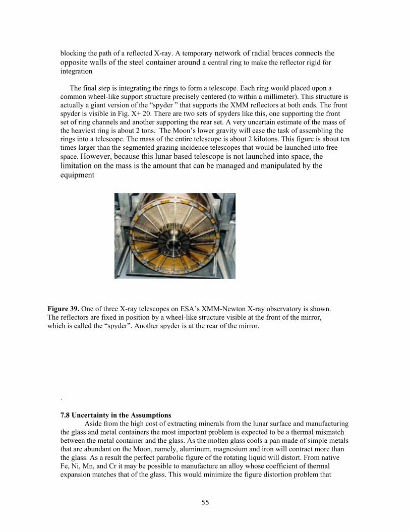
55
blocking the path of a reflected X-ray. A temporary network of radial braces connects the opposite walls of the steel container around a central ring to make the reflector rigid for integration The final step is integrating the rings to form a telescope. Each ring would placed upon a common wheel-like support structure precisely centered (to within a millimeter). This structure is actually a giant version of the “spyder ” that supports the XMM reflectors at both ends. The front spyder is visible in Fig. X+ 20. There are two sets of spyders like this, one supporting the front set of ring channels and another supporting the rear set. A very uncertain estimate of the mass of the heaviest ring is about 2 tons. The Moon’s lower gravity will ease the task of assembling the rings into a telescope. The mass of the entire telescope is about 2 kilotons. This figure is about ten times larger than the segmented grazing incidence telescopes that would be launched into free space. However, because this lunar based telescope is not launched into space, the limitation on the mass is the amount that can be managed and manipulated by the equipment . 7.8 Uncertainty in the Assumptions Aside from the high cost of extracting minerals from the lunar surface and manufacturing the glass and metal containers the most important problem is expected to be a thermal mismatch between the metal container and the glass. As the molten glass cools a pan made of simple metals that are abundant on the Moon, namely, aluminum, magnesium and iron will contract more than the glass. As a result the perfect parabolic figure of the rotating liquid will distort. From native Fe, Ni, Mn, and Cr it may be possible to manufacture an alloy whose coefficient of thermal expansion matches that of the glass. This would minimize the figure distortion problem that
Figure 39. One of three X-ray telescopes on ESA’s XMM-Newton X-ray observatory is shown. The reflectors are fixed in position by a wheel-like structure visible at the front of the mirror, which is called the “spyder”. Another spyder is at the rear of the mirror.

56
would occur when the molten glass cools and solidifies. Unless the coefficients of thermal expansion match we are unlikely to achieve the desired one arc second figure accuracy.
There are certain characteristic of fluids, which could be “showstopper” problems. The list includes surface tension in the molten glass. That would become increasingly important as the molten glass cools. It would tend to act against the formation of the parabolic figure. Perhaps it can neutralized by increasing the centrifugal force slightly through adjustment of the rate of rotation while the glass is molten. Capillary action of the molten glass with the container is another process affecting the figure. Its effect would be most profound at the top of the parabola where the thickness of the glass goes to zero. The figure would almost certainly be distorted at the fine end but perhaps only a small portion of the area is affected. It may be that certain glass formulations will exhibit better behavior for this process. Small quantities of additives will affect the thermal and mechanical properties of the molten and solid glass and possibly alleviate some of the adverse effects of surface tension and capillary action.
The glass that is used for ground based optical telescopes on Earth is premium quality.Mackenzie and Claridge have described several types of glass and ceramics that can be made from lunar materials. It is not clear which of these if any would be suitable material for the telescope making procedure described in this report. We would certainly require a purer, higher quality glass than what a lunar industry needs to produce for routine construction and insulation materials. Producing a higher quality product on the Moon from lunar materials for a grazing incidence telescope would be an additional reqirement but we cannot say that it would be prohibitive or impossible. Fortunately, unlike most applications for glass we have no restrictions on the color or transparency of the product. We also require that the steel containers we envision as containers for the molten glass will not become too weak as their temperature is raised or conversely that the glass is molten at a comparatively low temperature.
In summary, on its own the cost of manufacturing an X-ray telescope on the Moon from
lunar maerials would exceed the cost of launching a telescope of the same effective area from the Earth to the Sun-Earth L2 point, the preferred locale for an ultra-high throughput X-ray astronomy observatory. We have not identified a fundamental reason why it would not be possible to manufacture a 30m X-ray telescope on the Moon from lunar materials. The existence of a lunar base with infrastructure that provides transportation, materials, and construction services at no cost to UXT would profoundly change the relative cost picture.

57
8 Launch and Propulsion 8.1 Requirements Propulsion systems play a large role in the launch and operations of the Ultra-High Throughput X-Ray Observatory. The list of propulsion services that the Ultra High Throughput Observatory requires is: • Launch the 200+ ton telescope to L2 in 10 or fewer operations • Launch several detector spacecraft to L2 • Station keeping or maintaining the L2 site amidst perturbations from the Moon and planets • Attitude control of the telescope and, to lower accuracy, the attitude of the active detector • Formation flying between the large telescope spacecraft and a detector spacecraft • Changing targets by rotating the telescope to the new pointing position and displacing the
detector from the old focus to the new focus all within a time of 2 hours or less 8.2 The Journey from LEO to L2 Certainly the most challenging aspect of this program is placing the 200 ton Ultra High Throughput telescope in space at a cost that is tolerable. The launching of the much lower mass detector satellites is relatively straight forward by comparison. The high cost of placing payloads in space affects virtually every program. It is obvious that conventional chemical rockets are not the correct instruments for taking a payload from low Earth orbit to L2 if the cost is to be kept under control. Finding lower cost and novel methods of doing so is in fact the subject of several NIAC programs. Although it may be premature we had made it a part of this program as well. Co-investigators at the Glenn Research Center (GRC) and Dynacs Co. carried out a study of how the requirements of UXT could be satisfied with newer technology ion engines. The success of the Deep Space 1 mission, recently concluded, has greatly bolstered the prospects for electric propulsion playing an important role in space. Heavy ions that are accelerated only a few hundred volts deliver much higher specific impulse (thrust per unit flow rate of propellant, measured in seconds) than chemical rockets. Table 8 lists the specific impulse of various type rocket engines. Table 8 Specific Impulse of various types of Rocket Engines
Engine Type Specific Impulse (sec) • Chemical 150-450 • Nuclear Thermal 825-925 • ARCJET (Electrothermal) 800-1200 • MPD (Electromagnetic) 2000-5000 • ION (Electrostatic) 3500-10000
Furthermore with solar energy in abundance it is wasteful to devote part of the payload capacity to carrying the energy source. The great advantage of chemical rockets is the ability to move a payload rapidly to higher orbit. However, speed is not important in lifting payloads from LEO to L2. The large thrust of chemical rockets operating for only a short time can make a great deal of difference at certain critical turns. However, we find that most of the time the much lower thrust of ion engines is sufficient. For the most part it is not important much time is required to lift a UXT detector or mirror module group as long as it can be accomplished in less than a year. Also, ion engines can perform multiple functions. After arriving at L2 the ion engines can be

58
reprogrammed to control the attitude of the mirror, detectors, and displace the detector for target changes. The engine’s thrust would be resized to a value more appropriate for its new task. Two variations of a “store-burn” procedure were modeled for the voyage from LEO to L2. The engine operates at 100 kW; solar energy is stored in a flywheel. With an assist from a small chemical rocket near the end a payload of 3 tons is delivered while some 1.5 tons of propellant is consumed. The time is a year and cost is about $15m. There are several possible means of ascending from LEO to L2 slowly. Fig. 40 illustrates two. The method shown in the upper panel uses only electric propulsion operating on solar power with a flywheel storage system. The thrusters operate episodically at the optimum positions along the continually changing orbit to nudge the spacecraft towards L2. Another method adds a relatively low cost chemical rocket to deliver a brief but strong impulse near the end when most of the distance has traversed. The effect of the added impulse (“a sharp left towards alpha Centauri”) is to reduce the time it takes to close in on L2 considerably.

59
Figure 40. Ascending slowly from LEO to L2 with electric propulsion only (upper panel). Adding a small chemical rocket to deliver an impulse when most of the distance has been traversed. to close in on L2 much faster at the end (lower).

60
9 Future Activities 9.1 Enabling technologies Required All of the issues discussed in this report require new technology. The most critical of these are: • development of X-ray telescopes of much lower mass that satisfy the angular resolution
requirement of 1 arc second HPD or better; a problem of developing suitable substrate materials and methods of figure formation involving one or two levels of adaptive optics,
• lower cost launches to LEO and from LEO to L2, • achieving a rendezvous with another spacecraft at L2, • robotic assembly of components in space with dexterity, in this case attaching new mirror
modules and solar cells to the telescope with millimeter accuracy placement, • formation flying to a precision of one millimeter in three dimensions at separations of
hundreds of meters for filled aperture optics, tens of kilometers for sparse aperture telescopes, and up to thousands of kilometers for Fresnel optics .
9.2 Telescope Architectures All three architectures, the conventional filled aperture, the sparse aperture Kirkpatrick-Baez, and the Fresnel types should be considered candidates for a future Ultra-High Throughput X-ray Observatory. At this time, the conventional filled aperture telescope looks like the most promising of the three. Scientists and engineers on the Constellation X-Ray Mission and XEUS programs are developing Wolter 1 optics further. State of the art technology in lightweight mirrors will emerge from those programs. The investigation of the membrane mirror substrates, which appears to be particularly suitable for sparse aperture Kirkpatrick-Baez optics should be encouraged. It is not now the most promising telescope architecture for UXT but does have the potential to be a much lower mass instrument than the modular filled aperture telescope. It merits more study. UXT shares a need for these enabling technologies with other space ventures. NASA should support scientists for study of the optics. Aerospace research companies should be supported for study of the space flight technologies such as less expensive launches, achieving a rendezvous, and for construction and assembly of optics in situ. The most critical of these is lower cost launch capability. 9.2 Pathfinder Missions Formation flying, communications and other aspects of mission operations could be tested prior to UXT under less demanding conditions prior to the development with a pathfinder mission. An excellent candidate telescope is a smaller, 4m hard X-ray imaging telescope with multiplayer coatings. It does not require high angular resolution or its the adaptive optics features, and also is more tolerant of formation flying. The depth of focus is 2m and the other tolerances depend only on how large a detector we can field. This instrument would be capable of fulfilling several scientific objectives. One, its effective area below 20 keV is more then ten times larger than RXTE. The image is defocused to a large size so that with a matrix of discrete solid

61
state detectors, silicon drift detectors in series along the optic axis with CadTel, very high count rates can be processed with little dead time. The important temporal variation studies involving general relativistic effects would be extended. Two, it would have 25 times larger effective area at 50 keV than the Con-X HXT including hard X-ray spectroscopy of AGNs and compact binary systems. Three, it has an effective area of over 3000 cm2 at 158 keV, the energy of a gamma-ray from the decay of Ni56 , which powers the early phases of Type 1a supernova. It is emitted at a time when the debris is becoming more transparent. Fluctuations in the shape of the spectrum and the intensity of the line will allow us to trace the debris. Many Type 1a supernova can be observed each year. Comparing the gamma-ray histories, emission and absorption, of supernovas is an independent assessment of the standard candle hypothesis that has revolutionized cosmology by suggesting that the expansion of the universe is accelerating. The 4 m telescope can be folded to fit within the payload envelope of a Delta 3 rocket. The detector can be accommodated as well or launched separately and perform a rendezvous. 9.3 Propulsion, End Note Fortunately NASA is showing considerable interest in the subject of propulsion recently. NASA is issuing NRA 02-0SS-01 which includes an element entitled, “In-Space Propulsion Technologies (ISPT)”. Funding levels are expected to increase especially next year and the year after..

62
10. References Angel, J. R. P., Davison, W. B., Hill, J. M E., Mannery, J.,and Martin, H. M. SPIE 1236, 636, 1990 Barkana, R. and Loeb. A. 2001, In the Beginning: The First Sources of Light and the Reionization of the Universe, (to appear in Physics Reports) Bekey, I., “Assessment of the Feasibility of Extremely Large, Structureless Optical Telescopes and Arrays”, NIAC Phase 1 Study Final Report, 1999, http://www.niac.usra.edu/studies/ Borra, E. F. Canadian Journal of Physics, 73, 109, 1995 Borra, E. F. Ritcey, A. and Artigau, E. Ap. J. Letters, 516, L115, 1999 Brandt, W. N.; Alexander, D. M.; Hornschemeier, A. E.; Garmire, G. P.; Schneider, D. P.; Barger, A. J.; Bauer, F. E.; Broos, P. S.; Cowie, L. L.; Townsley, L. K.; Burrows, D. N.; Chartas, G.; Feigelson, E. D.; Griffiths, R. E.; Nousek, J. A.; 2001 Sargent, W. L. W. The Chandra Deep Field North Survey. V. 1 Ms Source Catalogs, astro-ph 0108404 Cash, W. “Reflection Grating Spectrometer on board XMM”, IN: High-energy astrophysics in the 21st century; Proceedings of the Workshop, Taos, NM, Dec. 11-14, 1989 (A91-47977 20-90), 139-143; Discussion, p. 143, 144 New York, American Institute of Physics Cen, R. and Ostriker, J.P, 1999 “Where Are the Baryons?”, Ap. J., 514:16 Cen, R. and Ostriker, J.P. “Cosmic Chemical Evolution”, 1999, Ap. J., 519:L109L113, 10. Cohen, L. 2001 (SAO Proposal to NASA and To appear in final report for NIAC/USRA Grant NAG5-8992) Criswell, D. R. and D. R. Waldron. 1982. Lunar Utilization. In CRC Handbook on Space Industrialization., ed B. O'Leary. 2: 1-53. Boca Raton, FL. Criswell D. R. et al. 1980. Extraterrestrial Materials Processing and Construction (Final Report). Delivered to NASA. Available National Technical Information Service. Contract NSR-09-051-001 (Mod. #24). Lunar and Planetary Inst., Houston, TX. 77058. 1119 pp. Criswell D. R. et al. 1978. Extraterrestrial Materials Processing and Construction (Final Report). Delivered to NASA-Johnson Space Center, available from the National Technical Information Service. Contract NSR-09-051-001 (Mod. 24). Lunar and Planetary Inst., Houston TX. 77058. 474 pp. Di Stefano, R., Ford, L.H., Yu, H-W, Fixsen, D.J., 2001, Quantum Gravity and Astrophysics: The Microwave Background and Other Thermal Sources, astro-ph 0107001

63
Dewey, Daniel; Markert, Thomas H.; Schattenburg, Mark L. “Diffractive-optic telescope for x-ray astronomy”, SPIE 2808, 650, 1996. Elvis, M., Plummer, D., Schachter, J., Fabbiano, G, 1992, “The Einstein Slew Survey”, Ap. J. S. 80: 257-303. Fabricant, D. G., Cohen, L. and Gorenstein, P., . 1988, “X-ray performance of the LAMAR proto-flight mirror” Applied Optics” Vol. 27:1456. Fabricant, D., Conroy, M., Cohen, L., and Gorenstein, P., 1986 SPIE 597, 128. Forward, R. 1999, (Talk presented at Gossamer Workshop). Giacconi, R., Zirm, A., Wang, J., Rosati, P., Nonino, M., Tozzi, P., Gilli, R., Mainieri, V., Hasinger, G., L. Kewley, L., Bergeron, J., Borgani, S., Gilmozzi, R., Grogin, N., Koekemoer, A., Schreier, E., Zheng, W., Norman, C., 2001, Chandra Deep Field South: The 1Msec Catalog, astro-ph 0112184 (accepted for Ap. J. S.) Girad, L. and Borra, E. F. Appl. Opt., 36(35), 6278, 1997 Gorenstein. P, 1998, “Deployable ultrahigh-throughput x-ray telescope: concept”, SPIE Vol. 3444, p. 382-392. Gorenstein, P. 1994, (Paper presented at Annual Conference of the European Geophysical Society, Symposium on Science on the Moon and in Space) Hamburg. Hettrick, M.C, and Bowyer, S., 1983, in “Variable line-space gratings - New designs for use in grazing incidence spectrometers”, Applied Optics 22, 3921. Kelley, R. et al, 1998, “ASTRO-E high-resolution x-ray spectrometer”, SPIE Vol. 3765, p. 114-127. Koch, D. et al, 1996, “System design of a mission to detect Earth-size planets in the inner orbits of solar-like stars”, JGR Vol. 101, p. 9297-9302. Kohk, Peter, 1996 Aboriginal Lunar Production of Glass, Moon Miner’s Manifesto No. 96, http://www.asi.org/adb/06/09/03/02/096/lunar-glass-production.html Landis, Geoffrey A., Glassmaking on the Moon. http://www.asi.org/adb/02/13/01/glass-production.html Mackenzie, J. D., and Claridge, R., Glass and Ceramics from Lunar Materials, Space Manufacturing Facilities 3, 135, AIAA, NY 1979 Main, J. A, Martin, J. and Nelson, G., 1999, “Non-contact Shape Control of Membrane Mirrors” , Proceedings of the Ultra lightweight Optics Challenge Workshop, March 24-25, Napa Ca. Schnopper, H. W. et al, “X-ray optics made from thin plastic foils”, SPIE Vol. 3766, p. 350-361. Monoz, J. A., Kochanek, C. S., and Falco, E.E. 1999, Finding Gravitational Lenses with X-rays, Ap. J. 521 L17

64
Schwartz, D. A. 2001, X-Ray Jets As Cosmic Beacons (submitted to Ap. J.) Shibata, R. et al. 1998, “X-ray calibration of telescopes on board the ASTRO-E satellite”, SPIE Vol. 3444, p. 598-609. Silver, E. H. et al, 2000, “NTD-Ge microcalorimeters”, SPIE Vol. 4140, 397. Van Speybroeck, L. P. (private communication), 2000 Stamper, Brian; Angel, Roger; Burge, James; and Woolf, Neville 2000, Flat Membrane Mirrors for Space Telescopes, http://caao.as.arizona.edu/publications/FlatMirror2.pdf Verhoeve, P. et a. 2000 ,“Development of superconducting tunnel junctions for soft X-ray spectroscopy”, SPIE Vol. 4140 (in press). Voges, W. et al, 1999, “The ROSAT All-Sky Survey Bright Source Catalogue”, astro-ph/9909315 and A&A 349, 389-405. Waldron, R. D. and D. R. Criswell. 1982. Processing of Lunar Materials. In CRC Handbook on Space Industrialization, ed. B. O'Leary. 1: 94-130. Boca Raton, FL. Wittenberg, L.J., Santarius, J.F., and Kulcinski, G.L, Lunar Source of 3He for Commercial Fusion Power. Fusion Technology 10:167-178, 1968.

I
Appendix A: Detecting Distant Quasars Comparison of XEUS with UXT
The ESA brochures on the XEUS mission science and mission summary contain a simulation of the observation of a distant quasar by the XEUS Phase 2 observatory. According to ESA the XEUS Phase 2 telescope will have an effective area of 30 square meters. The luminosity of the quasar is assumed to be 10E42 ergs/sec, z = 4, and the exposure is 100 ksec. The objective is to measure the strength and redshift of the iron K line which is detected at 1.5 keV. The line is broadened by scattering and by a differential gravitational redshift as observed for much closer AGNs. The XEUS simulation of the energy spectrum is reproduced here and another set of points have been added to the plot that simulates the performance of UXT with 250 square meters of collecting area.
Figure A-1. Simulation of spectra of XEUS, open squares (red) and UXT filled circles (blue) in
100 ksec observation of quasar at z = 4 with intrinsic luminosity of 10E42 ergs/sec.
Comparison of the two sets of points with the actual spectrum (the histogram) shows the effect of improved counting statistics. Analysis of the XEUS data would not provide a good measurement of the mean energy and width of the line. There is a large upward statistical fluctuation at 2 keV and the highest energy points do not provide a good enough measurement of the continuum to be subtracted for studying the line. The scatter of the UXT points above and below the assumed spectrum is much less. UXT would provide good measurements of z, the strength of the line and its width, for determination of the distance, the elemental abundance, and conditions near the event horizon of the black hole.

The rate of change in momenturm equals this force, or F = dm/dt*v
This is the maximum force. The average force is about half of this.
Milli_Newtons 352.468−=Milli_Newtons 103 δF⋅:=Force in MilliNewtons:
δF 0.352−=δF 3− F⋅
L
1000
R⋅:=
newtonsF 4.092 103×=gravitational force on satelliteF m g⋅ReR
2⋅:=
L
1000
R2.871 10 5−
×=g 9.8=m 500=
F = GMm/R^2 dF/dR = -3*GMm/R^3
dF = -3*F(dR/R)
Consider that phase of the orbital when the telescope axis is along a radial direction to theEarth's center. At those two points the detector is istantaneously in a circular orbit that iseither higher or lower in altitude than the telescope by L. The propulsion system providesthe force that either adds to or subtracts from the force of gravity.
R 6.966 103×=R Re h+:=
Re 6.366 103×=
kg, mass of detector satelliteincluding fuel for propulsion system
m 500:=Earth's radius in kmRe400002 π⋅
:=
m/sec^2, accel. of Earth's gravityg 9.8:=orbital altitude in kmh 600:=
fixed distance between telescope and detector, in meters, or the focallength of the telescope
L 200:=
Consider special case, telescope satellite is in a circular orbit and its pointing direction is inthe orbital plane. Gas jets or ion engine drives on the detector satellite provide a propulsion system that maintainsa fixed distance.
AppendiX B:Estimate of Mass Consumption and Power Level Needed to Sustain the Alignment of Two Satellites at a Fixed Separation and Alignment,Station Keeping Between Telescope and Detector Aboard SeparateSatellites.
1

Calculate the velocity of a singly charged Xe ion falling through a Voltage, E, in volts
Velocity E M,( ) 2E 10 9−⋅
M
⋅
C⋅:= Where both E and M are in GeV
Mass of Xenon Ion M 131:= E 750:= V Velocity E M,( ):=
V 3.21 104×= Meters/sec
MdotδFV
:= Mdot 1.098− 10 5−×= kilograms/sec
M0 300:= Fuel Supply kilograms
TM0Mdot
:= T 2.732 107×= Seconds
Days of Operation DaysT
86400:= Days 316.241=
Fuel Consumption: Chemical Rockets
h 600= kilometers
Take V as twice the sound velocity, about 1750 m/sec for NH-3 at 1200 K
V1200 1000⋅
3600:= V 1750:= meters/sec
MdotδFV
:= Mdot 2.014− 10 4−×= kilograms/sec
M0 300:= Fuel Supply kilograms
TM0Mdot
:= T 1.489 106×= Seconds
Days of Operation DaysT
86400:= Days 17.24=
Fuel Consumption: Electric Propulsion
C 3 108⋅:= Velocity of Light
2

δF_2δF
0.333−=Ratio of force perpendicularto plane to force in plane and also ratio of power and propellanconsumption.
Milli_Newtons 117.489=Milli_Newtons 103 δF_2⋅:=Force in MilliNewtons:
δF_2 0.117=δF_2 F tan Theta( )⋅:=
Theta 2.871 10 5−×=Theta atan
L
1000
R
:=
newtonsF 4.092 103×=
distance from center, kmR 6.966 103×=focal lenth, metersL 200=
Consider the Case where the Optic Axis is Perpendicular to the Obital Plane. The Effect of the Thrust Upon the Detector is to Displace the Apparent Center of the Earth a Distance Equal to the Focal Length. For a Force, δF, Normal to the Gravity Force, F
This is the maximum power. Avg Power is about halfBut still very substantial.
watts Power 6.005 103×=Power E Current⋅:=
Current 8.006=Current Atoms_sec Q⋅:=Atoms_sec 5.004 1019×=
Atoms_secMdot−
M Mn⋅:=
Mass Atom in amuM 131=Atoms_sec
MdotM Mn⋅
:=Mass Neutorn in kgMn 1.675 10 27−
⋅:=
Elect. Chrg in coulQ 1.6 10 19−⋅:=Estimate Power Level From Ion Current
3

I
Appendix C: Lunar Glass Manufacturing and Mining References Criswell D. R. et al. 1978. Extraterrestrial Materials Processing and Construction (Final Report). Delivered to NASA-Johnson Space Center, available from the National Technical Information Service. Contract NSR-09-051-001 (Mod. 24). Lunar and Planetary Inst., Houston TX. 77058. 474 pp. Criswell D. R. et al. 1980. Extraterrestrial Materials Processing and Construction (Final Report). Delivered to NASA. Available National Technical Information Service. Contract NSR-09-051-001 (Mod. #24). Lunar and Planetary Inst., Houston, TX. 77058. 1119 pp. Criswell, D. R. and D. R. Waldron. 1982. Lunar Utilization. In CRC Handbook on Space Industrialization., ed B. O'Leary. 2: 1-53. Boca Raton, FL. Kohk, Peter, 1996 Aboriginal Lunar Production of Glass, Moon Miner’s Manifesto No. 96, http://www.asi.org/adb/06/09/03/02/096/lunar-glass-production.html Landis, Geoffrey A., Glassmaking on the Moon. http://www.asi.org/adb/02/13/01/glass-production.html J. D. Mackenzie and R. Claridge, Glass and Ceramics from Lunar Materials, Space Manufacturing Facilities 3, 135, AIAA, NY 1979 Waldron, R. D. and D. R. Criswell. 1982. Processing of Lunar Materials. In CRC Handbook on Space Industrialization, ed. B. O'Leary. 1: 94-130. Boca Raton, FL.