analog placement based on symmetry-island formulation
TRANSCRIPT

IEEE TRANSACTIONS ON COMPUTER-AIDED DESIGN OF INTEGRATED CIRCUITS AND SYSTEMS, VOL. 28, NO. 6, JUNE 2009 791
Analog Placement Based onSymmetry-Island Formulation
Po-Hung Lin, Yao-Wen Chang, Member, IEEE, and Shyh-Chang Lin
Abstract—To reduce the effect of parasitic mismatches andcircuit sensitivity to thermal gradients or process variations foranalog circuits, some pairs of modules need to be placed symmet-rically with respect to a common axis, and the symmetric modulesare preferred to be placed at closest proximity for better elec-trical properties. Most previous works handle the problem withsymmetry constraints by imposing symmetric-feasible conditionsin floorplan representations and using cost functions to minimizethe distance between symmetric modules. Such approaches areinefficient due to the large search space and cannot guarantee theclosest proximity of symmetry modules. In this paper, we presentthe first linear-time-packing algorithm for the placement withsymmetry constraints using the topological floorplan representa-tions. We first introduce the concept of a symmetry island whichis formed by modules of the same symmetry group in a singleconnected placement. Based on this concept and the B∗-tree rep-resentation, we propose automatically symmetric-feasible (ASF)B∗-trees to directly model the placement of a symmetry island. Wethen present hierarchical B∗-trees (HB∗-trees) which can simulta-neously optimize the placement with both symmetry islands andnonsymmetric modules. Unlike the previous works, our approachcan place the symmetry modules in a symmetry group in closeproximity and significantly reduce the search space based on thesymmetry-island formulation. In particular, the packing time foran ASF-B∗-tree or an HB∗-tree is the same as that for a plainB∗-tree (only linear) and much faster than previous works. Experi-mental results show that our approach achieves the best-publishedquality and runtime efficiency for analog placement.
Index Terms—Analog circuit, floorplanning, physical design,placement.
I. INTRODUCTION
FOR ANALOG layout design, some pairs of modules needto be placed symmetrically with respect to a common axis.
The symmetric placement has several advantages: It reducesthe effect of parasitic mismatches which may lead to higheroffset voltages and degrade power-supply rejection ratio [2].It can also reduce the circuit sensitivity to process variations
Manuscript received May 31, 2008; revised October 15, 2008 and January 6,2009. Current version published May 20, 2009. This paper was presented in partat the 2007 ACM/IEEE Design Automation Conference (DAC’07) [1]. Thiswork was supported in part by Springsoft, by Etron, by TSMC, and by theNational Science Council of Taiwan under Grants NSC-096-2917-I-002-121,NSC 93-2815-C-002-046-E, NSC 94-2215-E-002-005, and NSC 94-2752-E-002-008-PAE. This paper was recommended by Associate Editor H. E. Graeb.
P.-H. Lin is with the Graduate Institute of Electronics Engineering, NationalTaiwan University, Taipei 106, Taiwan (e-mail: [email protected]).
Y.-W. Chang is with the Graduate Institute of Electronics Engineering andthe Department of Electrical Engineering, National Taiwan University, Taipei106, Taiwan (e-mail: [email protected]).
S.-C. Lin is with the Physical Design Group, Springsoft, Inc., Hsinchu 300,Taiwan (e-mail: [email protected]).
Color versions of one or more of the figures in this paper are available onlineat http://ieeexplore.ieee.org.
Digital Object Identifier 10.1109/TCAD.2009.2017433
by placing the symmetric devices closed to each other. Failureto adequately balance thermal coupling in a differential circuitcan even introduce unwanted oscillations [3]. Furthermore,the symmetric modules are preferred to be placed at closestproximity for better parasitic matching and other electricalproperties.
A. Previous Work
The problem of analog placement considering symmetryconstraints has been extensively studied in the literature. Mostof these works used the simulated-annealing (SA) algorithm[4] in combination with floorplan representations to handlesymmetry constraints. We can classify these representationsinto two major categories: 1) the absolute representation and2) the topological representation.
An absolute representation was proposed by Jepsen andGellat [5]. For this representation, each module is associ-ated with an absolute coordinate on a gridless plane. It op-erates on a module by changing its coordinate directly. TheKOAN/ANAGRAM II [2], PUPPY-A [6], and LAYLA [7]systems all adopted the absolute representation to handle theplacement of analog modules. The main weakness of the ab-solute method lies in the fact that it may generate an infeasibleplacement with overlapped modules. Therefore, a postprocess-ing step must be performed to eliminate this condition, whichimplies a longer computation time.
Recently, most previous works apply topological floor-plan representations due to its flexibility and effectiveness.Balasa et al. derived the symmetric-feasible conditions forseveral popular floorplan representations including sequencepairs (SPs) [8], O-tree [9], and binary trees [10]. To explorethe solution space in the symmetric-feasible binary trees, theyaugmented the B∗-tree [11] using various data structures, in-cluding segment trees [3], [12], red–black trees [13], and de-terministic skip lists [14]. Lin et al. [15] also presented thesymmetric-feasible conditions for the TCG-S representation.Three more recent works [16]–[18] further took advantage ofthe symmetric-feasible condition in SPs [8]. Koda et al. [16]proposed a linear-programming-based method, and Tam et al.[17] introduced a dummy node and additional constraint edgesfor each symmetry group after obtaining a symmetric-feasibleSP. Krishnamoorthy et al. [18] proposed an O(m · n lg lg n)packing-time algorithm by employing the priority queue, wherem is the number of symmetry groups and n is the numberof modules. More recently, Zhang et al. [19] further im-proved the perturbation time of the TCG representation fromO(n2) to O(n).
0278-0070/$25.00 © 2009 IEEE
Authorized licensed use limited to: National Taiwan University. Downloaded on December 27, 2009 at 13:42 from IEEE Xplore. Restrictions apply.
792 IEEE TRANSACTIONS ON COMPUTER-AIDED DESIGN OF INTEGRATED CIRCUITS AND SYSTEMS, VOL. 28, NO. 6, JUNE 2009
Most of the previous works showed that the symmetric-feasible conditions in the topological representations can han-dle the placement problem with a symmetry group effectively.However, it is time-consuming to generate a relatively largerscale placement with several symmetry groups. For example,Koda et al. [16] reported that it takes almost an hour on a3.2-GHz Pentium PC to generate a symmetric placement of110 modules with five symmetry groups.
We observed several problems/deficiencies in the previousworks for analog placement: First, most previous works em-ployed either an initial scan or a postprocessing with penaltyto avoid or fix the violation of the symmetric-feasible con-dition for each perturbation during the SA process. There isno direct representation that can guarantee the symmetric-feasible condition in the representation itself. It is clear thatsuch approaches are inefficient due to the large search space andfixing overheads. Consequently, the previous works using topo-logical floorplan representations need O(m · n lg lg n) time forpacking n modules. Second, most previous works used costfunctions or weights to penalize the solution with symmetricmodules far from each other. Obviously, such approaches can-not guarantee the close proximity (or even the adjacency) ofsymmetry modules.
B. Our Contributions
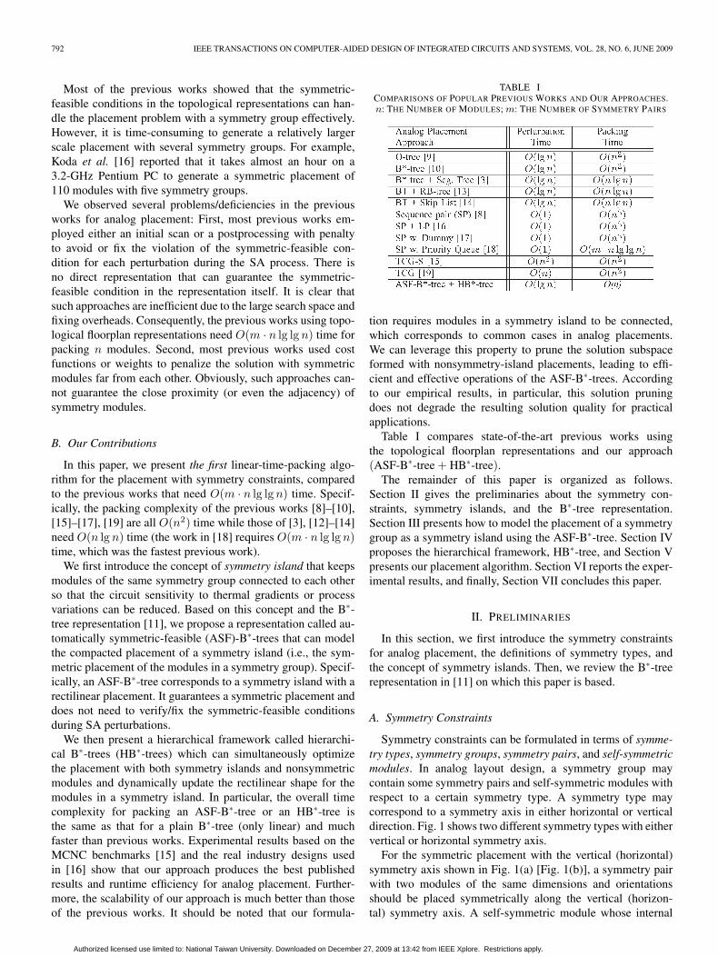
In this paper, we present the first linear-time-packing algo-rithm for the placement with symmetry constraints, comparedto the previous works that need O(m · n lg lg n) time. Specif-ically, the packing complexity of the previous works [8]–[10],[15]–[17], [19] are all O(n2) time while those of [3], [12]–[14]need O(n lg n) time (the work in [18] requires O(m · n lg lg n)time, which was the fastest previous work).
We first introduce the concept of symmetry island that keepsmodules of the same symmetry group connected to each otherso that the circuit sensitivity to thermal gradients or processvariations can be reduced. Based on this concept and the B∗-tree representation [11], we propose a representation called au-tomatically symmetric-feasible (ASF)-B∗-trees that can modelthe compacted placement of a symmetry island (i.e., the sym-metric placement of the modules in a symmetry group). Specif-ically, an ASF-B∗-tree corresponds to a symmetry island with arectilinear placement. It guarantees a symmetric placement anddoes not need to verify/fix the symmetric-feasible conditionsduring SA perturbations.
We then present a hierarchical framework called hierarchi-cal B∗-trees (HB∗-trees) which can simultaneously optimizethe placement with both symmetry islands and nonsymmetricmodules and dynamically update the rectilinear shape for themodules in a symmetry island. In particular, the overall timecomplexity for packing an ASF-B∗-tree or an HB∗-tree isthe same as that for a plain B∗-tree (only linear) and muchfaster than previous works. Experimental results based on theMCNC benchmarks [15] and the real industry designs usedin [16] show that our approach produces the best publishedresults and runtime efficiency for analog placement. Further-more, the scalability of our approach is much better than thoseof the previous works. It should be noted that our formula-
TABLE ICOMPARISONS OF POPULAR PREVIOUS WORKS AND OUR APPROACHES.n: THE NUMBER OF MODULES; m: THE NUMBER OF SYMMETRY PAIRS
tion requires modules in a symmetry island to be connected,which corresponds to common cases in analog placements.We can leverage this property to prune the solution subspaceformed with nonsymmetry-island placements, leading to effi-cient and effective operations of the ASF-B∗-trees. Accordingto our empirical results, in particular, this solution pruningdoes not degrade the resulting solution quality for practicalapplications.
Table I compares state-of-the-art previous works usingthe topological floorplan representations and our approach(ASF-B∗-tree + HB∗-tree).
The remainder of this paper is organized as follows.Section II gives the preliminaries about the symmetry con-straints, symmetry islands, and the B∗-tree representation.Section III presents how to model the placement of a symmetrygroup as a symmetry island using the ASF-B∗-tree. Section IVproposes the hierarchical framework, HB∗-tree, and Section Vpresents our placement algorithm. Section VI reports the exper-imental results, and finally, Section VII concludes this paper.
II. PRELIMINARIES
In this section, we first introduce the symmetry constraintsfor analog placement, the definitions of symmetry types, andthe concept of symmetry islands. Then, we review the B∗-treerepresentation in [11] on which this paper is based.
A. Symmetry Constraints
Symmetry constraints can be formulated in terms of symme-try types, symmetry groups, symmetry pairs, and self-symmetricmodules. In analog layout design, a symmetry group maycontain some symmetry pairs and self-symmetric modules withrespect to a certain symmetry type. A symmetry type maycorrespond to a symmetry axis in either horizontal or verticaldirection. Fig. 1 shows two different symmetry types with eithervertical or horizontal symmetry axis.
For the symmetric placement with the vertical (horizontal)symmetry axis shown in Fig. 1(a) [Fig. 1(b)], a symmetry pairwith two modules of the same dimensions and orientationsshould be placed symmetrically along the vertical (horizon-tal) symmetry axis. A self-symmetric module whose internal
Authorized licensed use limited to: National Taiwan University. Downloaded on December 27, 2009 at 13:42 from IEEE Xplore. Restrictions apply.

LIN et al.: ANALOG PLACEMENT BASED ON SYMMETRY-ISLAND FORMULATION 793
Fig. 1. Two symmetry types. (a) Symmetric placement with the verticalsymmetry axis. (b) Symmetric placement with the horizontal symmetry axis.
TABLE IINOTATIONS IN THIS PAPER
structure is self-symmetric must have its center placed at thesymmetry axis.
We use the notations listed in Table II throughout this paper.Let S = {S1, S2, . . . , Sm} be a set of m symmetry groupswhose coordinate(s) of the symmetry axis (axes) is (are) de-noted by xi or yi (xi and yi), 1 ≤ i ≤ n. A symmetry groupSi = {(b1, b
′1), (b2, b
′2), . . . , (bp, b
′p), b
s1, b
s2, . . . , b
sq} consists of
p symmetry pairs and q self-symmetric modules, where (bj , b′j)
denotes a symmetry pair and bsk denotes a self-symmetric mod-
ule. Let (xj , yj) and (x′j , y
′j) denote the respective coordinates
of the centers of two modules bj and b′j in a symmetry pair(bj , b
′j), respectively, and (xs
k, ysk) denotes the coordinate of
the center of the self-symmetric module bsk. The symmetric
placement of a symmetry group Si with the vertical (horizontal)symmetry axis must satisfy (1) [(2)]
xj + x′j =2 × xi ∀j = 1, 2, . . . , p
yj = y′j ∀j = 1, 2, . . . , p
xsk = xi ∀k = 1, 2, . . . , q (1)
xj =x′j ∀j = 1, 2, . . . , p
yj + y′j =2 × yi ∀j = 1, 2, . . . , p
ysk = yi ∀k = 1, 2, . . . , q. (2)
B. Symmetry Island
Before introducing the symmetry island, we shall first inves-tigate the effect of the symmetric device layout on the electricalmatching properties of the symmetric devices. Pelgrom et al.[20] measured the mismatch between MOS transistors withvarious electrical parameters as a function of device areas, dis-tances, and orientations. According to Pelgrom et al. [20], thedifference of an electrical parameter P between two rectangulardevices is modeled by the standard deviation, as shown in (3),where AP is the area proportionality constant for P , W and L
denote the respective width and length of the device, and SP
denotes the variation of P under the device spacing Dx
σ2(ΔP ) =A2
P
WL+ S2
P D2x. (3)
We assume that the device dimensions of modules in asymmetry pair are the same. According to the above equation,the larger the distance between the symmetry pair, the greaterdifferences between their electrical properties. Therefore, itis of significant importance for the symmetric devices of asymmetry group to be placed in close proximity. Fig. 2(a) showsan analog circuit of a two-stage CMOS operational amplifiercontaining the differential input subcircuit. The devices M1,M2, M3, M4, and M5 in the differential input subcircuitform a symmetry group S = {(M1,M2), (M3,M4),M5}.Fig. 2(b) and (c) shows two corresponding layouts with dif-ferent placement styles for the symmetry group S. The layoutstyle in Fig. 2(c) is generally considered much better than thatin Fig. 2(b) because the symmetric modules of the same sym-metry group are placed at closer proximity (or even adjacent)to each other. Consequently, the sensitivities due to processvariations can be minimized, and the circuit performance canbe improved.
Based on the placement with the closest proximity for asymmetry group as shown in Fig. 2(c), we introduce the conceptof symmetry islands and give its definition as follows.
Definition 1: A symmetry island is a placement of a symme-try group in which each module in the group abuts at least oneof the other modules in the same group, and all modules in thesymmetry group form a connected placement.
We further use the example in Fig. 3 to explain the concept ofsymmetry islands. The symmetry group S1 in Fig. 3(a) forms asymmetry island but that in Fig. 3(b) does not, since it results intwo disconnected components. The placement style in Fig. 3(a)is preferred in analog layout design due to its better electricalproperties.
C. Review of B∗-Trees
Since this paper is based on the B∗-tree representation [11],we shall first give a brief review over the representation. AB∗-tree is an ordered binary tree representing a compactedplacement, in which every module can no longer move left andbottom. As shown in Fig. 4, every node of a B∗-tree correspondsto a module of a compacted placement. The root of a B∗-tree corresponds to the module on the bottom-left corner. Foreach node n corresponding to a module b, the left child of nrepresents the lowest adjacent module on the right side of b,while the right child of n represents the first module above bwith the same horizontal coordinate.
Given a B∗-tree, we can calculate the coordinate of eachmodule by a preorder tree traversal. Suppose the module bi,represented by the node ni, has the bottom-left coordinate(xi, yi), the width wi, and the height hi. Then, for the left childnj of ni, xj = xi + wi; for the right child nk of ni, xk = xi.In addition, we maintain a contour structure to calculate they-coordinates. Thus, starting from the root node, whose bottom-left coordinate is (0, 0), then visiting the root’s left subtree and,
Authorized licensed use limited to: National Taiwan University. Downloaded on December 27, 2009 at 13:42 from IEEE Xplore. Restrictions apply.

794 IEEE TRANSACTIONS ON COMPUTER-AIDED DESIGN OF INTEGRATED CIRCUITS AND SYSTEMS, VOL. 28, NO. 6, JUNE 2009
Fig. 2. Example analog circuit and two different layout styles for the circuit. (a) Schematic of a two-stage CMOS operational amplifier, where the differentialinput subcircuit forms a symmetry group. (b) Layout design of the circuit in (a), where the devices of a symmetry group are not placed close to each other.(c) Another layout design of the circuit in (a), where the devices of a symmetry group are placed close to each other.
Fig. 3. Two symmetric-placement examples of a symmetry group S1 ={(b1, b′1), (b2, b′2)}. (a) S1 forms a symmetry island. (b) S1 cannot form asymmetry island.
Fig. 4. (a) Compacted placement [same as in Fig. 3(a)]. (b) B∗-tree represent-ing the compacted placement in (a).
then, its right subtree, this preorder-tree-traversal procedure,also known as B∗-tree packing, calculates all coordinates ofthe modules in the placement. Using a doubly linked list toimplement the contour structure, the total packing time is linearto the number of modules.
III. PLACEMENT OF A SYMMETRY GROUP
In this section, we propose the ASF-B∗-tree to consider thesymmetric placement of a symmetry group and the packingof the symmetry modules to make a symmetry island. Like
Fig. 5. (a) Placement example of a symmetry group with a vertical symmetryaxis. (b) Selecting a representative for each symmetry pair and self-symmetricmodule. (c) ASF-B∗-tree (also a representative B∗-tree) representing the place-ment of the symmetry group, where the dash circled nodes represent the left-boundary modules.
B∗-trees, the ASF-B∗-tree can represent only compacted sym-metric placement; in particular, there exists a unique corre-spondence between a compacted symmetric placement of asymmetry group and its induced ASF-B∗-tree which results ina symmetry island. We first present the definitions and prop-erties of the ASF−B∗-tree and then prove the correspondencebetween a symmetry island and its induced ASF-B∗-tree.
Before introducing the ASF-B∗-tree, we should define therepresentative of a symmetry pair, the representative of a self-symmetric module, and the representative B∗-tree.
Definition 2: The representative brj of a symmetry pair
(bj , b′j) is b′j .
Definition 3: The representative brk of a self-symmetric mod-
ule bsk is the right (top) half of bs
k in a symmetric placement withrespect to a (horizontal) symmetry axis.
For the example shown in Fig. 5, the representative br1 of the
symmetry pair {b1, b′1} is b′1, while the representative br
0 of theself-symmetric module bs
0 is the right half of bs0.
Authorized licensed use limited to: National Taiwan University. Downloaded on December 27, 2009 at 13:42 from IEEE Xplore. Restrictions apply.

LIN et al.: ANALOG PLACEMENT BASED ON SYMMETRY-ISLAND FORMULATION 795
It should be noted that each symmetry pair or self-symmetricmodule must have its own representative module. Therefore, thenumber of the representatives in a symmetry group should bethe same as the number of symmetry pairs and self-symmetricmodules. We define the representative B∗-tree as follows.
Definition 4: A representative B∗-tree is a B∗-tree containingonly the representative nodes that correspond to representativemodules.
In the following, we describe how to obtain an ASF-B∗-treeby making a representative B∗-tree symmetric feasible for sym-metric placements with vertical and horizontal symmetry axes.We first introduce the mirrored placement of the representativemodules for a symmetry group.
Definition 5: The mirrored placement of the representativemodules for a symmetry group Si is to place the nonrepresen-tative modules on the mirrored positions of the representativeones for each symmetry pair or each self-symmetric module inSi with respect to its symmetry axis (axes). Furthermore, therepresentative and the nonrepresentative modules of each self-symmetric module are not disjointed.
We are now ready to define the symmetric-feasible conditionof a representative B∗-tree for the symmetric placements.
Definition 6: A representative B∗-tree is symmetric feasibleif the mirrored placement of the representative modules can beobtained after packing the representative B∗-tree.
In Fig. 5(a), the modules in the symmetry group S ={(b1, b
′1), b
s0, b
s2, b
s3} are placed symmetrically with respect to
the vertical axis. To construct the corresponding representativeB∗-tree, we should select the representative module of eachsymmetry pair and self-symmetric module and consider theplacement on the right half-plane. Fig. 5(b) shows the rep-resentative modules, and Fig. 5(c) shows the correspondingrepresentative B∗-tree of the symmetric placement. Each nodein the representative B∗-tree corresponds to a representativemodule.
To make the representative B∗-tree symmetry symmetric fea-sible, we have the following lemmas which gives the symmetrycondition for a self-symmetric module and a symmetry pair.
Lemma 1: The representative of a self-symmetric modulemust abut the symmetry axis.
Proof: Let S be a symmetry group with a vertical symme-try axis and bs be a self-symmetric module in S. The symmetryaxis of S is denoted by x, and the center of bs is denoted by(xs, ys).
Based on (1), the symmetry axis x always passes through thecenter (xs, ys) of the self-symmetric module bs, i.e., x = xs.According to Definition 3, the representative br of bs is the righthalf of bs. Therefore, the center (xs, ys) of bs must be on theleft boundary of br. To keep the symmetric-feasible conditionx = xs, br must abut the symmetry axis x. The case for asymmetry group with a horizontal symmetry axis can be provedsimilarly. Q.E.D.
Lemma 2: The representative of a symmetry pair not on asymmetry axis is always symmetric feasible.
Proof: Let S be a symmetry group with a vertical symme-try axis and (b, b′) be a symmetry pair in S. The symmetry axisof S is denoted by x. The respective centers of b and b′ are (x, y)and (x′, y′), and the respective widths/heights of b and b′ are
Fig. 6. (a) Placement example of a symmetry group with a horizontal sym-metry axis. (b) Selecting a representative module for each symmetry pairand self-symmetric module. (c) ASF-B∗-tree (also a representative B∗-tree)representing the placement of the symmetry group, where the dash circlednodes represent the bottom-boundary modules.
w/h and w′/h′, where w = w′ and h = h′. The representativeof the symmetry pair (b, b′) is b′.
Given the coordinate of the representative b′ and the verticalsymmetry axis x, the coordinate of the symmetric module b canbe calculated by (1). We have x = 2 × x − x′ and y = y′. Aftertransposing x to the left side and having the absolute value onboth sides, we have |x − x| = |x − x′|. Since the representativeis not on the symmetry axis, we have |x − x| = |x − x′| ≥w/2. It means that the distances from the symmetry axis tothe centers of b and b′ are greater than or equal to half of thewidth of b or b′. Since b and b′ are on different sides of thesymmetry axis, b and b′ will not overlap each other. Therefore,the symmetric-feasible condition is always satisfied. The casefor a symmetry group with a horizontal symmetry axis can beproved similarly. Q.E.D.
According to Lemma 1 and the boundary constraints [21] inthe B∗-trees, we have the following property for the symmetric-feasible representative B∗-trees representing 1-D symmetricplacement.
Property 1: The left-boundary (right-boundary) constraintfor the symmetric placement with respect to a vertical (horizon-tal) symmetry axis: The representative node of a self-symmetricmodule should always be on the rightmost (leftmost) branch ofthe representative B∗-tree.
Based on the above property, the nodes representing the mod-ules on the left boundary should be on the rightmost branch, asshown in Fig. 5(c).
Similarly, we can get the symmetric-feasible representativeB∗-tree of the symmetric placement when the symmetry axisis in the horizontal direction. In this case, we only considerthe top half-plane during the placement of the representativemodules. Fig. 6(c) shows the representative B∗-tree of thesymmetry group S = {(b0, b
′0), b
s1, b
s2, b
s3} having the symmet-
ric placement with respect to the horizontal symmetry axisin Fig. 6(a). Again, the representatives of the self-symmetricmodules should abut the horizontal symmetry axis which is onthe bottom boundary of the top half-plane. Therefore, the nodesrepresenting the modules on the bottom boundary should be onthe leftmost branch, as shown in Fig. 6(c).
Based on Definition 4 and Property 1, we define an ASF-B∗-tree as follows.
Definition 7: An ASF-B∗-tree is a representative B∗-treewhich satisfies Property 1.
Once an ASF-B∗-tree is packed, the coordinates of theserepresentatives are obtained. We can further calculate the
Authorized licensed use limited to: National Taiwan University. Downloaded on December 27, 2009 at 13:42 from IEEE Xplore. Restrictions apply.

796 IEEE TRANSACTIONS ON COMPUTER-AIDED DESIGN OF INTEGRATED CIRCUITS AND SYSTEMS, VOL. 28, NO. 6, JUNE 2009
coordinates of their symmetric modules based on (1) and (2)with the given coordinates of the symmetry axes, xi and yi.Then, we have the symmetric placement of a symmetry group,and it automatically forms a symmetry island.
Based on Lemmas 1 and 2, we have the following theorems.Theorem 1: An ASF-B∗-tree is symmetric feasible in a sym-
metric placement of a symmetry group with respect to either avertical or a horizontal symmetry axis.
Proof: An ASF-B∗-tree is symmetric feasible if allthe representatives in the ASF-B∗-tree are symmetric fea-sible. There are four kinds of representatives, and thesymmetric-feasible condition for each is defined and provedin Lemmas 1 and 2. Therefore, an ASF-B∗-tree is symmet-ric feasible in a symmetric placement of a symmetry groupwith respect to either a vertical or a horizontal symmetryaxis. Q.E.D.
Theorem 2: The packing of an ASF-B∗-tree results in asymmetry island of the corresponding symmetry group.
Proof: It is obvious that all the representative moduleswill form a connected placement after packing. We set thecoordinate(s) of the symmetry axis (axes) to the left or (and) thebottom boundary (boundaries) of the connected placement ofthe representative modules. The coordinates of the symmetricmodules can be calculated by (1) and (2). The symmetricmodules also form a connected placement, and the boundaryof the connected placement also abut the symmetry axis (axes).Therefore, the whole symmetry group forms a connected place-ment, and each module in the group abuts at least one of theother modules in the same group. The packing of an ASF-B∗-tree, thus, results in a symmetry island of the correspondingsymmetry group. Q.E.D.
Theorem 3: There exists a unique correspondence betweena compacted symmetric placement of a symmetry group and itsinduced ASF-B∗-tree.
Proof: According to Chang et al. [11], there is a uniquecorrespondence between an admissible placement and its in-duced B∗-tree. After obtaining the placement of the repre-sentative modules, we simply get the mirrored placement ofthe symmetric ones. The mirrored placement is also unique.Therefore, there exists a unique correspondence between acompacted symmetric placement of a symmetry group and itsinduced ASF-B∗-tree. Q.E.D.
Based on the earlier theorems, we can correctly find acorresponding symmetric placement for an ASF-B∗-tree veryefficiently, by avoiding searching in redundant solution spaces.It will be clear later in Section VI that these nice properties ofASF-B∗-trees lead to superior solution quality and efficiencyfor analog placement.
IV. HIERARCHICAL FRAMEWORK
We propose a hierarchical framework, called hierarchicalB∗-tree (HB∗-tree for short), to handle the simultaneous place-ment of modules in symmetry islands and nonsymmetric mod-ules. In an HB∗-tree, the symmetry island of each symmetrygroup can be in any rectilinear shapes, and symmetry andnonsymmetric modules are simultaneously placed to optimizethe placement.
Fig. 7. HB∗-tree for the placement in Fig. 3(a).
Fig. 8. (a) ASF-B∗-tree of a symmetry group S0. (b) Horizontal and verticalcontours of the corresponding placement. (c) Symmetry island and its effectivecontours. (d) HB∗-tree for the rectilinear symmetry island.
A. HB∗-Tree Representation
Fig. 7 shows an HB∗-tree for the placement in Fig. 3(a). Twosymmetry groups, S1 and S2, are represented by two hierarchynodes, nS1 and nS2 , and each hierarchy node contains an ASF-B∗-tree that corresponds to a symmetry island in the symmetricplacement.
The symmetry islands are often not rectangular but are of rec-tilinear shapes. For example, in Fig. 8(c), the symmetry islandof the symmetry group S0 is of the rectilinear shape. Therefore,we should augment the HB∗-tree in Fig. 7 to handle rectilinearsymmetry islands. Wu et al. [22] proposed a method to dealwith rectilinear modules by slicing a rectilinear module intoseveral rectangular submodules along each vertical boundary.However, it is complicated to maintain the relationship betweenthe submodules during B∗-tree perturbations.
Instead of slicing a rectilinear symmetry island, we introducecontour nodes to represent top horizontal contour segments ofthe symmetry island. In Fig. 8(c), there are three horizontalcontour segments: c00, c01, and c02. We augment the HB∗-treeby introducing the three contour nodes, n00, n01, n02, as shownin Fig. 8(d). Each contour node keeps the coordinates of thecorresponding horizontal contour segment. The relationship ofa hierarchy node, its contour nodes, and other regular modulenodes is described as follows.
Property 2: Properties for an HB∗-tree.
1) The left child of a hierarchy node, if any, must be anoncontour node.
2) The right child of a hierarchy node must be the contournode representing the leftmost top horizontal contoursegment of the symmetry island.
Authorized licensed use limited to: National Taiwan University. Downloaded on December 27, 2009 at 13:42 from IEEE Xplore. Restrictions apply.

LIN et al.: ANALOG PLACEMENT BASED ON SYMMETRY-ISLAND FORMULATION 797
3) The left child of a contour node, if any, must be thecontour node representing the next contour segment onthe right side.
4) The right child of a contour node, if any, must be anoncontour node.
5) The children of a regular module node must be noncon-tour nodes.
6) The parent of a contour node cannot be a regular modulenode.
Proof: Given a symmetry group S0, bS0 denotes the sym-metry island of S0, nS0 denotes the corresponding hierarchynode, and n0i represents the ith top contour segment of bS0
from left to right.
1) Since the contour node n0i represents the ith top contoursegment of bS0 , it is impossible for n0i to be the left childof nS0 that corresponds to the lowest adjacent module onthe right side of bS0 , based on the B∗-tree definition. Theproperty thus follows.
2) According to the definition of the B∗-tree, the right childof nS0 represents the first module above bS0 . Since thetop horizontal contour segments of bS0 always abut bS0 ,other modules cannot be placed between bS0 and its topcontour segments. Therefore, the right child of nS0 mustbe a contour node representing the leftmost top horizontalcontour segment of bS0 .
3) By the contour-node definition, the contour node n0,i
represents the ith top contour segment of bS0 from leftto right, and the left child of n0,i, if any, is n0,i+1,representing the next [(i + 1)th] contour segments. If n0,i
represents the last (the rightmost) top contour segment,the left child of n0i is empty.
4) The right child of the contour node n0i represents the firstmodule above the ith top contour segment of bS0 . If thereexists another contour node n0j that is the right child ofn0i, both contour segments will overlap each other withn0j’s contour segment on top of that of n0i, implying thatn0i is not a contour node. A contraction.
5) Based on the second and the third properties of the HB∗-tree, the contour node n0i cannot be the left or right childof a regular module node. The property thus follows.
6) Based on the construction of the HB∗-tree, the parent of acontour node is either a contour node or a hierarchy node.
Q.E.D.Fig. 8(a) shows the ASF-B∗-tree of the symmetry group
S0 = {(b0, b′0), (b1, b
′1), (b2, b
′2)}. In Fig. 8(b), the horizontal
and vertical contours are obtained from the rectilinear outlineafter packing the ASF-B∗-tree. Fig. 8(c) shows the symmetryisland and the effective horizontal and vertical contours. Thehorizontal contour segments are denoted as c00, c01, and c02
from left to right. Therefore, we have a hierarchy node nS0
representing the symmetry island of the symmetry group S0,and three contour nodes n00, n01, and n02 representing thecontour segments. The relationship between the hierarchy nodeand its contour nodes is shown in the HB∗-tree in Fig. 8(d).
After introducing the representation and the properties ofHB∗-trees, we present the packing procedure for ASF-B∗-treesand HB∗-trees.
Fig. 9. Packing procedure including the contour updates of the ASF-B∗-treein Fig. 8(a).
Fig. 10. Generation of the bottom contour of the symmetry island based onthe dual vertical contours. (a) Convex points obtained by traversing the dualvertical contours from bottom to top. (b) Bottom horizontal contour connectedby the convex points.
B. ASF-B∗-Tree Packing
The packing of the ASF-B∗-tree is similar to that of theB∗-tree [11] which follows the preorder-tree-traversal proce-dure to calculate the coordinates of the modules. During thepacking, two double-linked lists are implemented to keep bothhorizontal and vertical contour structures. Fig. 9 shows thepacking procedure of the example ASF-B∗-tree in Fig. 8(a). Thebold (red) lines denote the horizontal contour, while the dotted(green) lines represent the vertical contour.
After obtaining the coordinates of all representative modulesin the symmetry group, we can calculate the coordinates ofthe symmetric modules and the extended contours based oneither (1) or (2). Fig. 8(b) shows the resulting placement of thesymmetry group and the contours of the symmetry island forthe ASF-B∗-tree shown in Fig. 8(a). As shown in Fig. 8(b), thesymmetry island contains one top horizontal and dual verticalcontours. To further calculate the bottom horizontal contour ofthe symmetry island, we need to traverse both vertical contoursfrom bottom to top and keep the convex points as shown inFig. 10(a). By connecting the convex points horizontally, wecan obtain the bottom horizontal contour of the symmetryisland, as shown in Fig. 10(b).
C. HB∗-Tree Packing
The HB∗-tree packing also adopts the preorder-tree-traversalprocedure. When a hierarchy node is traversed, the ASF-B∗-tree in the hierarchy node should be packed first to obtainthe contours of the symmetry island described previously. Thecontours are then stored in the corresponding hierarchy node.During packing a hierarchy node representing a symmetryisland, we should calculate the best packing coordinate for thebottom boundary of the symmetry island, based on the bottomcontour shown in Fig. 10(b). We then proceed to pack theleft child of the hierarchy node. After the left child and allits descendants are packed, we pack the first contour node ofthe symmetry island, followed by the second one, and so on.When packing the contour nodes, we only need to update their
Authorized licensed use limited to: National Taiwan University. Downloaded on December 27, 2009 at 13:42 from IEEE Xplore. Restrictions apply.

798 IEEE TRANSACTIONS ON COMPUTER-AIDED DESIGN OF INTEGRATED CIRCUITS AND SYSTEMS, VOL. 28, NO. 6, JUNE 2009
Fig. 11. (a) HB∗-tree representing 20 modules with two symmetry groups S0
and S1. (b) Resulting placement after packing the HB∗-tree.
coordinates and replace the hierarchy node in the contour datastructure of the HB∗-tree.
Fig. 11(a) shows an HB∗-tree representing 20 modules withtwo symmetry groups S0 and S1. For the packing, the two ASF-B∗-trees in nS0 and nS1 are packed first, and the rectilinearoutlines of the two symmetry islands are obtained. Then, thenodes, n5, n6, n7, n8, and n9, are packed in the depth-firstsearch order. The temporal contour list is 〈n5, n6, n7, n9〉. Bycalculating the rectilinear outlines between the temporal con-tour list and the bottom boundary of the symmetry island S0,the dead space between the previously packed modules and thesymmetry island can be minimized. The updated temporal con-tour list becomes 〈nS0 , n7, n9〉. Continuing the packing pro-cedure, we can obtain the resulting placement of the HB∗-treein Fig. 11(b) finally. Although the purpose of the packing isto obtain a compacted placement, we might need to allocatesufficient white space for the surrounding wells or guard ringsbased on the device types, such as NMOS or PMOS transistors.When packing a node, the device type of the correspondingmodule should be compared with those of the previouslypacked modules in the current contour list. If the device typesare different, the currently packed module should be snapped toa position to reserve sufficient white space for the surroundingwells or guard rings.
We have the following theorem for the packing complexity.Theorem 4: The packing for an ASF-B∗-tree or an HB∗-tree
takes linear time.Proof: Given a design with n modules (including symme-
try and nonsymmetry ones) and m symmetry groups, let n bethe number of nonsymmetric modules and n(Si) be the numberof modules in each symmetry group Si, where n(Si) ≥ 1. Wehave n = n +
∑mi=1 n(Si).
For the HB∗-tree representing the symmetric placement ofthe given design, there are m hierarchy nodes, O(
∑mi=1 n(Si))
contour nodes, and n module nodes. For the ASF-B∗-tree ofthe symmetry group Si in a hierarchy node, there are O(n(Si))representative nodes.
We first consider the packing for the ASF-B∗-tree of thesymmetry group Si in a hierarchy node. It consists of two steps.The first step is the packing for all representative modules.The second step is the calculation of the coordinate of eachsymmetric module.
According to Chang et al. [11], the packing for a B∗-treetakes linear time, so the time complexity of the first step isO(n(Si)). Since it takes constant time to calculate the coor-dinate of a symmetric module, it also takes O(n(Si)) time tocompute the coordinates of all the symmetric modules in Si.Combining both steps, we have the O(n(Si)) time complexityfor the packing of an ASF-B∗-tree of Si.
Second, we consider the packing for the HB∗-tree. If all thesymmetry islands of m symmetry groups are in a rectangularshape. We can ignore the contour nodes in the HB∗-tree, andit takes O(m + n) time to pack the HB∗-tree. However, if anysymmetry island is in a rectilinear shape, we need to considerthe packing of the hierarchy node representing this symmetryisland, particularly the additional contour nodes.
The bottom contour of the symmetry island of Si is obtainedwhen the corresponding ASF-B∗-tree of the symmetry groupis packed, and the number of the bottom contour segments isO(n(Si)). By comparing the current packing contour segmentsand the bottom contour segments of the symmetry island fromleft to right, it also takes O(n(Si)) time to get the coordinatesof the modules in the symmetry island Si.
To sum up, it takes O(m +∑m
i=1 n(Si) + n) time to packthe HB∗-tree. Since n =
∑mi=1 n(Si) + n, the packing time can
be reduced to O(m + n) time. Since the number of symmetrygroup m is upper bounded by the number of total modules n,the packing time is O(n). Q.E.D.
It should be noted that this is the fastest algorithm in the lit-erature for the placement with symmetry constraints, as shownin Table I.
D. Advanced Symmetry Constraints
For some analog layout applications, the symmetry con-straints could be even more complex than what we have con-sidered. We brief the handling of two kinds of such symmetryconstraints in the following.
1) Multiple Symmetry-Group Alignment: In some analoglayouts, the symmetry axes of different symmetry groups arerequired to be aligned to share a common symmetry axis. Toalign multiple symmetry groups with respect to a commonvertical (horizontal) symmetry axis, we can insert a zero-height (zero-width) dummy block right at the left (bottom)of each to-be-aligned symmetry island. We then introduce adummy node as the parent of the hierarchy node representingthe corresponding symmetry island in the HB∗-tree, where thehierarchy node is the left (right) child of the dummy node.By adjusting the width (height) of each dummy block, thesymmetry islands of different symmetry groups can be alignedwith respect to a common vertical (horizontal) symmetry axis.Such an alignment technique is an extension of the workin [23].
2) Hierarchical Symmetry: In some fully symmetric analogdesigns, the device layouts should be hierarchically symmetric.
Authorized licensed use limited to: National Taiwan University. Downloaded on December 27, 2009 at 13:42 from IEEE Xplore. Restrictions apply.

LIN et al.: ANALOG PLACEMENT BASED ON SYMMETRY-ISLAND FORMULATION 799
A symmetry group Si may also contain a self-symmetry groupSs
j and/or a symmetry-group pair (Sk, S ′k). Consequently, the
top-level symmetry group STop contains all device modulesand other symmetry groups hierarchically. Based on the pro-posed symmetry-island and tree formulations, a hierarchicaltree structure [24] that mixes both the ASF-B∗-trees and theHB∗-trees can be constructed. The optimized fully symmetricplacement with the hierarchical symmetry constraint can thenbe obtained by searching a desired configuration of the treestructure and packing the trees to form the symmetry islandshierarchically.
E. Application to Hierarchical Clustering Constraint
Besides handling the symmetry constraints based on thesymmetry-island formulation, the proposed hierarchical frame-work, HB∗-trees, can also effectively manage the hierarchicalclustering constraint in analog placement or mixed-signal floor-planning based on the intrinsic hierarchical tree structure.
Let C = {C1, C2, . . . , Cl} be a set of device module clus-ters. Each cluster contains at least two modules, or one moduleand one of the other clusters, or two of the other clusters. If thecluster Ci contains the cluster Cj , we call Ci a supercluster andCj a subcluster. The hierarchical clustering constraint limits allthe device modules and/or subclusters of the same superclusterto a connected placement.
To formulate the hierarchical clustering constraint usingthe HB∗-trees, each of the hierarchy nodes nC1 , nC2 , . . . , nCl
denotes a cluster. Each hierarchy node nCifurther contains
another HB∗-tree to represent the topological relation of thedevice modules and/or the subclusters in the supercluster de-noted by nCi
. After hierarchically constructing the HB∗-trees,the placement can be optimized by searching a desired con-figuration of the HB∗-trees while the inner placement of eachcluster is connected.
F. Consideration of Nonsymmetry-Island Placements
In addition to the preferred symmetry-island placementsin analog layouts, the proposed ASF-B∗-trees and HB∗-treescan also generate a nonsymmetry-island placement by inte-grating nonsymmetric modules as a self-symmetric modulecluster or a symmetry pair consisting of two module clustersin a symmetry group represented by an ASF-B∗-tree. Fig. 12shows two examples, including the symmetric placements andthe corresponding ASF-B∗-trees, which integrate nonsymmet-ric module clusters into symmetry groups. In Fig. 12(a), thenonsymmetric modules, b3 and b4, form the self-symmetricmodule cluster C1 in the symmetry group S1. After packingthe B∗-tree representing the placement of the nonsymmetricmodules, the representative node nr
C1is introduced in the ASF-
B∗-tree representing a symmetric placement of S1. Similarly,in Fig. 12(b), the nonsymmetric modules, b7, b8, and b9, formtwo clusters, C2 and C ′
2, as a symmetry pair in the symmetrygroup S2. In the corresponding ASF-B∗-tree, the representativenode nr
C2is introduced to denote the larger dimensions of the
placements of C2 and C ′2.
Fig. 12. Integrating nonsymmetric modules into symmetry groups. (a) Non-symmetric modules form the self-symmetric module cluster C1 = {b3, b4} inthe symmetry group S1 = {(b1, b′1), (b2, b′2), Cs
1}. (b) Nonsymmetric mod-ules form two clusters, C2 = {b7, b8} and C′
2 = {b9}, as a symmetry pair inthe symmetry group S2 = {bs
5, (b6, b′6), (C2, C′2)}.
V. ALGORITHM
Our algorithm is based on the SA [4]. Given a set of modulesand symmetry constraints as the inputs, we construct an initialsolution represented by an HB∗-tree and, then, perturb it tosearch for a desired configuration until a predefined terminationcondition is satisfied. The cost function Φ(P ) of the placementis defined in (4), where α and β are user-specified parameters,AP is the area of the bounding rectangle for the placement, andWP is the half-perimeter wire length
Φ(P ) = α × AP + β × WP . (4)
A. HB∗-Tree Perturbation
We apply the following operations to perturb an HB∗-tree.1) Op1: Rotate a module.2) Op2: Move a node to another place.3) Op3: Swap two nodes.In the perturbation, the nonhierarchy nodes have higher prob-
abilities to be selected because rotating, moving, or swappingthe hierarchy nodes might incur a big jump in finding the nextsolution. It is well known that such a big jump might deterioratethe solution quality during the SA process. It should be notedthat, due to the special structure of the HB∗-tree, we cannotmove a nonhierarchy node to the right child of a hierarchy nodeor the left child of a contour node. The contour nodes are alwaysmoved along with its hierarchy node which cannot be movedindividually.
B. ASF-B∗-Tree Perturbation
In addition to the aforementioned Op1, Op2, and Op3 forHB∗-tree perturbation, we introduce the operations, Op4 andOp5, to perturb the ASF-B∗-trees. It should be noted thatProperty 1 should always be satisfied when perturbing an ASF-B∗-tree according to the definition of the ASF-B∗-trees inDefinition 7.
1) Op4: Change a representative.2) Op5: Convert a symmetry type.
Authorized licensed use limited to: National Taiwan University. Downloaded on December 27, 2009 at 13:42 from IEEE Xplore. Restrictions apply.

800 IEEE TRANSACTIONS ON COMPUTER-AIDED DESIGN OF INTEGRATED CIRCUITS AND SYSTEMS, VOL. 28, NO. 6, JUNE 2009
Fig. 13. Rotating the self-symmetric module bs1 in the symmetry group
S = {bs0, bs
1} results in the shape change of its representative br1.
1) Module Rotation: When rotating modules in a symmetrygroup, the corresponding ASF-B∗-tree is unchanged. We shouldconsider two cases of symmetry-module rotation.
Case 1) Rotate a symmetry pair.Case 2) Rotate a self-symmetric module.In case 1), both modules of a symmetry pair should be rotated
at the same time so that they can still be symmetrically placedwith respect to a symmetry axis. In case 2), after rotating aself-symmetric module, the shape of its representative shouldbe updated accordingly, as shown in Fig. 13.
2) Node Movement: When moving a node to another place inan ASF-B∗-tree, we should consider the following two cases.
Case 1) Move a node representing the representative of asymmetry pair.
Case 2) Move a node representing the representative of aself-symmetric module.
In case 1), we can move the representative node of a sym-metry pair to anywhere in an ASF-B∗-tree. In case 2), however,we can only move the representative node of a self-symmetricmodule along the rightmost (leftmost) branch of the ASF-B∗-tree for vertical (horizontal) symmetric placement so thatProperty 1 is satisfied.
3) Node Swapping: When swapping two nodes in an ASF-B∗-tree, we consider the following two cases.
Case 1) Both nodes represent the representatives of twodifferent symmetry pairs.
Case 2) At least one node represents the representative of aself-symmetric module.
In case 1), we can arbitrarily swap two nodes representing therepresentatives of two different symmetry pairs. However, weshould be very careful for case 2). If at least one of the swappednodes represents the representative of a self-symmetric module,the other node must be located on the same branch (i.e., the left-most or the rightmost branch) of the ASF-B∗-tree. Therefore,Property 1 is still satisfied after node swapping.
4) Representative Change: The purpose of changing a rep-resentative for a symmetry pair or a self-symmetric module is tooptimize the wire length, while the area is kept unchanged afterchanging the representative. We can change the representativeof either a symmetry pair or a self-symmetric module.
Case 1) Change the representative of a symmetry pair.Case 2) Change the representative of a self-symmetric
module.In case 1), for a symmetry pair (bj , b
′j), we can simply change
the representative from bj to b′j or from b′j to bj . Fig. 14 showsthat changing the representative of the symmetry pair (b1, b
′1)
from b′1 to b1 may result in shorter wire length between b1 andb3. Similarly, in case 2), for a self-symmetric module bs
k, we canchange its representative by flipping it horizontally or vertically
Fig. 14. Changing the representative of the symmetry pair (b1, b′1) from b′1to b1 may result in shorter wire length between b1 and b3.
Fig. 15. Changing the representative of the self-symmetric module bs1 may
result in shorter wire length between bs1 and b3.
Fig. 16. Converting the symmetry type from (a) vertical symmetry to(b) horizontal symmetry.
Fig. 17. Converting the symmetry type from (a) horizontal symmetry to(b) vertical symmetry.
according to its symmetry axis. As shown in Fig. 15, changingthe representative of the self-symmetric module bs
1 by flippingit horizontally may result in shorter wire length between bs
1 andb3. Obviously, each operation takes constant time.
5) Symmetry-Type Conversion: For symmetry-type conver-sion of a symmetry group, we should consider both conversionsbetween the vertical symmetry and the horizontal one.
Case 1) Convert the symmetry type from vertical symmetryto horizontal one.
Case 2) Convert the symmetry type from horizontal symme-try to vertical one.
To convert the symmetry type of a symmetry group fromvertical symmetry to horizontal one or vice versa, we first rotateevery module including the representative and, then, swap theleft and the right children of each node in the given ASF-B∗-tree. Figs. 16 and 17 show the respective examples for theconversions of cases 1) and 2).
It should be noted that the symmetry type is usually pre-defined based on the power/ground lines or signal flows inthe layout by the analog designers. Therefore, Op5 is seldomapplied in real applications.
Authorized licensed use limited to: National Taiwan University. Downloaded on December 27, 2009 at 13:42 from IEEE Xplore. Restrictions apply.

LIN et al.: ANALOG PLACEMENT BASED ON SYMMETRY-ISLAND FORMULATION 801
Fig. 18. Example of updating contour-related nodes. (a) HB∗-tree and itscorresponding placement containing the symmetry group S0 = {(b0, b′0),(b1, b′1)}. (b) Intermediate HB∗-tree after perturbing the ASFB∗-tree in the hi-erarchy node nS0 and the corresponding symmetry island of S0. The contour-related nodes, n3 and n5, become dangling. (c) HB∗-tree after updating thecontour-related nodes and its corresponding placement.
C. Contour-Node-Related Updates
Once an ASF-B∗-tree is perturbed, the number of the cor-responding contour nodes in the HB∗-tree might be changed.The tree structure might have to be updated accordingly. If thenumber of contour nodes representing the horizontal contoursegments of the symmetry island is increased, the structure ofthe HB∗-tree can be kept unchanged. However, if that of thecontour nodes is decreased, some other nodes in the HB∗-treemight not have parents. We call such nodes dangling node,and we should reassign new parents for these nodes. To keepthe relative placement topology before and after perturbing anASF-B∗-tree, we first find the nearest contour node for eachdangling node. If the nearest contour node has no right child,it is the parent of the dangling node, and the dangling nodewill be its right child. If the nearest contour node has a rightchild, we continuously traverse the leftmost skewed child ofthe right child. The leftmost skewed child will be the parent ofthe dangling node, and the dangling node is assigned to its leftchild. It takes amortized constant time to update the contour-related nodes.
Fig. 18 shows an example of updating contour-related nodes.In Fig. 18(a), there are initially three contour nodes representingthe three top contour segments of the symmetry island of thesymmetry group S0. After performing Op2 to perturb the ASF-B∗-tree in nS0 , the representative node nr
1 is moved from theleft child to the right child of the other representative node nr
0.
TABLE IIIMCNC BENCHMARK CIRCUITS
TABLE IVINDUSTRY BENCHMARK CIRCUITS
The placement of S0 forms a new symmetry island, as shown inFig. 18(b) which has only one top contour segment. Therefore,the contour nodes n01 and n02 disappear, and the nodes n3 andn5 become dangling nodes. We first find the nearest contournode of n3, which is n00. Since n00 already has the right childn2, the leftmost skewed child of n2 should be searched. In thiscase, we directly assign n3 to be the left child of n2 because n2
has no left child. After n3 is assigned to a proper tree location,the nearest contour node of n5 is then searched, which is alson00. Since n00 already has the right child n2, the leftmostskewed child is searched, which is n3. We assign n3 to be theparent of n5, and n5 is the left child of n3.
VI. EXPERIMENTAL RESULTS
We implemented our placement algorithm in the C++ pro-gramming language on a 3.2-GHz Intel Pentium4 PC under theLinux operating system. We performed two sets of experiments:One is based on the four MCNC benchmarks (apte, hp, ami33,and ami49) used in [15], and the other consists of two realindustry analog designs (biasynth_2p4g and lnamixbias_2p4g)used in [12] and [16] (note that they both were extracted byKoda et al. [16] from [12, Figs. 9 and 10]). Table III liststhe names of the MCNC benchmark circuits (“Circuit”), thenumbers of modules (“# of Mod.”), the numbers of sym-metry modules (“# of Sym. Mod.”), and the total moduleareas (“Mod. Area”). Table IV lists the names of the indus-try benchmark circuits (“Circuit”), the numbers of modules(“# of Mod.”), the numbers of symmetry modules (“# ofSym. Mod.”), and the total module areas (“Mod. Area”).
Our approach is based on SA. A left skewed HB∗-tree wasconstructed as the initial solution. The initial temperature T0
was calculated by (5), where Δavg is the average uphill cost andP is the initial probability to accept uphill solutions. During theSA process, the temperature was reduced at the rate of 0.9 foreach subsequent pass, and 20 000 iterations were performed ateach temperature/pass
T0 = −Δavg/ ln P. (5)
In the first set of experiments, we compared our algorithmwith the following works: SPs [8], segment trees [3], TCG-S[15], and SPs with dummy nodes [17]. Table V lists the namesof the MCNC benchmark circuits (“Circuit”), the total areas
Authorized licensed use limited to: National Taiwan University. Downloaded on December 27, 2009 at 13:42 from IEEE Xplore. Restrictions apply.

802 IEEE TRANSACTIONS ON COMPUTER-AIDED DESIGN OF INTEGRATED CIRCUITS AND SYSTEMS, VOL. 28, NO. 6, JUNE 2009
TABLE VCOMPARISONS OF AREA UTILIZATION AND CPU TIMES FOR SP (ON SUN SPARC ULTRA-60 433 MHz), SEGMENT TREE (SEG. TREE) (ON SUN SPARC
ULTRA-60 433 MHz), TCG-S (ON SUN SPARC ULTRA-60 433 MHz), SP WITH DUMMY NODES (SP w. DUMMY) (ON PENTIUM4 3.2 GHz),AND OUR HB∗-TREE (ON PENTIUM4 3.2 GHz) WITH AREA OPTIMIZATION ALONE, SAME AS THE PREVIOUS WORKS, AND WITH
SIMULTANEOUS AREA AND WIRE-LENGTH OPTIMIZATION [HB∗-TREE (AREA+WL)], BASED ON THE MCNC BENCHMARKS
TABLE VICOMPARISONS OF AREA UTILIZATION AND CPU TIMES FOR SP (ON SUN BLADE 100 500 MHz), SEGMENT TREE (SEG. TREE)
(ON SUN BLADE 100 500 MHz), SP+LP (PENTIUM4 3.2 GHz), SP WITH DUMMY NODES (SP w. DUMMY) (ON PENTIUM4 3.2 GHz),AND HB∗-TREE (ON PENTIUM4 3.2 GHz), BASED ON TWO REAL INDUSTRY BENCHMARKS
(“Area”), and the runtimes (“Time”) for the aforementionedworks and our HB∗-tree with area optimization alone, same asthe previous works, and with simultaneous area and wire-lengthoptimization. The results of the works in [3], [8], and [15] aretaken from [15], and those of [17] are based on the packageprovided by the authors. The results show that our HB∗-treeachieves average area reductions of 3%, 2%, 1%, and 2% over[3], [8], [15], and [17], respectively. Note that the improvementsshould not be considered marginal, since the previous workshave pushed the solution quality close to their limits. The mainreason for the area improvement over the previous works isthat our approach benefits from both the symmetry-island for-mulation and the short packing time of the proposed floorplanrepresentations. Based on the symmetry-island formulation, theundesired solutions are pruned, and thus, we do not waste thetime to search inferior solutions during SA. With the shortpacking time, we can search for more solutions within the sametime limit. Consequently, our approach has greater possibilityto find better solutions in shorter running time. For the runningtime, our algorithm is about 4.09× faster than in [17]. Sinceall other previous works ran on different platforms, it is noteasy to report the speedups of our algorithm. Nevertheless, itis obvious from the table that our algorithm runs much fasterthan the previous works.
In the second set of experiments, we compared our algo-rithm with SPs in [8], segment trees in [12], SPs with linearprogramming in [16], and SPs with dummy nodes in [17].Table VI lists the names of the industry benchmark circuits,the total areas, and the runtime for SPs, segment trees, SPswith linear programming, SPs with dummy nodes, and HB∗-tree. The results show that our algorithm achieved averagearea reductions of 7.1%, 6.6%, 1.6%, and 10.3% over [8],[12], [16], and [17], respectively. In some applications, theorientations of analog device modules may not be allowed to
Fig. 19. Resulting placement of ami49 with simultaneous area and wire-length optimization, which contains the symmetry group, S = {(b19, b21),bs30, bs
48}.
be changed. To make fair comparisons with the previous works,we also performed our algorithm without module rotation. Ourresults show only 2.4% and 4% area overheads without therotation, compared to the results of SPs with linear program-ming [16] and our approach, respectively. For the running time,our approach achieves significant speedups over the previousworks, which is about 39.88× and 5.68× faster than thosein [16] and [17], respectively. Again, the previous works [8],
Authorized licensed use limited to: National Taiwan University. Downloaded on December 27, 2009 at 13:42 from IEEE Xplore. Restrictions apply.

LIN et al.: ANALOG PLACEMENT BASED ON SYMMETRY-ISLAND FORMULATION 803
Fig. 20. Resulting placement of biasynth_2p4g with three symmetry groups. (a) Resulting placement without module rotation. (b) Resulting placement withmodule rotation.
[12] ran on different platforms, and thus, we do not report thecorresponding speedups; yet, it is obvious that our algorithmruns much faster than the previous works. It is clear from thetwo experiments that our algorithm achieves the best qualityand efficiency than all published works.
Fig. 19 shows the resulting placement of ami49 with si-multaneous area and wire-length optimization, which containsthe symmetry group S = {(b19, b21), bs
30, bs48}. Fig. 20 shows
the resulting placements of biasynth_2p4g with the symmetrymodules being colored.
VII. CONCLUSION AND FUTURE WORK
We have proposed the first linear-time-packing algorithmfor the placement with symmetry constraints, based on thesymmetry-island formulation that prunes the solution subspaceformed with nonsymmetry-island placements. We have intro-duced the concept of symmetry islands and presented the ASF-B∗-trees to directly model the placement of a symmetry island.We have also presented the hierarchical HB∗-trees to simultane-ously optimize the placement with both symmetry islands andnonsymmetric modules. Experimental results have shown thatour approach achieves the best-published quality and runtimeefficiency for analog placement.
ACKNOWLEDGMENT
The authors would like to thank Prof. E. F. Y. Young andY.-C. Tam of the Chinese University of Hong Kong for provid-ing the package of their work [17] for the comparative studies.
REFERENCES
[1] P.-H. Lin and S.-C. Lin, “Analog placement based on novel symmetry-island formulation,” in Proc. ACM/IEEE Des. Autom. Conf., Jun. 2007,pp. 465–470.
[2] J. Cohn, D. Garrod, R. Rutenbar, and L. Carley, “KOAN/ANAGRAM II:New tools for device-level analog placement and routing,” IEEE J. Solid-State Circuits, vol. 26, no. 3, pp. 330–342, Mar. 1991.
[3] F. Balasa, S. Maruvada, and K. Krishnamoorthy, “Efficient solution spaceexploration based on segment trees in analog placement with symme-try constraints,” in Proc. IEEE/ACM Int. Conf. Comput.-Aided Des.,Nov. 2002, pp. 497–502.
[4] S. Kirkpatrick, C. D. Gelatt, Jr., and M. P. Vecchi, “Optimizationby simulated annealing,” Science, vol. 220, no. 4598, pp. 671–680,May 1983.
[5] D. Jepsen and C. Gelatt, Jr., “Macro placement by Monte Carlo anneal-ing,” in Proc. IEEE Int. Conf. Comput. Des., Nov. 1983, pp. 495–498.
[6] E. Malavasi, E. Charbon, E. Felt, and A. Sangiovanni-Vincentelli,“Automation of IC layout with analog constraints,” IEEE Trans.Comput.-Aided Design Integr. Circuits Syst., vol. 15, no. 8, pp. 923–942,Aug. 1996.
[7] K. Lampaert, G. Gielen, and W. Sansen, “A performance-driven place-ment tool for analog integrated circuits,” IEEE J. Solid-State Circuits,vol. 30, no. 7, pp. 773–780, Jul. 1995.
Authorized licensed use limited to: National Taiwan University. Downloaded on December 27, 2009 at 13:42 from IEEE Xplore. Restrictions apply.

804 IEEE TRANSACTIONS ON COMPUTER-AIDED DESIGN OF INTEGRATED CIRCUITS AND SYSTEMS, VOL. 28, NO. 6, JUNE 2009
[8] F. Balasa and K. Lampaert, “Symmetry within the sequence-pair repre-sentation in the context of placement for analog design,” IEEE Trans.Comput.-Aided Design Integr. Circuits Syst., vol. 19, no. 7, pp. 721–731,Jul. 2000.
[9] Y. Pang, F. Balasa, K. Lampaert, and C.-K. Cheng, “Block placement withsymmetry constraints based on the o-tree non-slicing representation,” inProc. ACM/IEEE Des. Autom. Conf., 2000, pp. 464–467.
[10] F. Balasa, “Modeling non-slicing floorplans with binary trees,” in Proc.IEEE/ACM Int. Conf. Compu.-Aided Des., 2000, pp. 13–16.
[11] Y.-C. Chang, Y.-W. Chang, G.-M. Wu, and S.-W. Wu, “B∗-trees: Anew representation for non-slicing floorplans,” in Proc. ACM/IEEE Des.Autom. Conf., 2000, pp. 458–463.
[12] F. Balasa, S. Maruvada, and K. Krishnamoorthy, “On the explorationof the solution space in analog placement with symmetry constraints,”IEEE Trans. Comput.-Aided Design Integr. Circuits Syst., vol. 23, no. 2,pp. 177–191, Feb. 2004.
[13] F. Balasa, S. Maruvada, and K. Krishnamoorthy, “Using red–black inter-val trees in device-level analog placement with symmetry constraints,”in Proc. IEEE/ACM Asia South Pacific Des. Autom. Conf., Jan. 2003,pp. 777–782.
[14] S. Maruvada, A. Berkman, K. Krishnamoorthy, and F. Balasa, “Determin-istic skip lists in analog topological placement,” in Proc. IEEE Int. Conf.ASIC, Oct. 2005, vol. 2, pp. 834–837.
[15] J.-M. Lin, G.-M. Wu, Y.-W. Chang, and J.-H. Chuang, “Placement withsymmetry constraints for analog layout design using TCG-S,” in Proc.IEEE/ACM Asia South Pacific Des. Autom. Conf., Jan. 2005, vol. 2,pp. 1135–1138.
[16] S. Koda, C. Kodama, and K. Fujiyoshi, “Linear programming-based cellplacement with symmetry constraints for analog IC layout,” IEEE Trans.Comput.-Aided Design Integr. Circuits Syst., vol. 26, no. 4, pp. 659–668,Apr. 2007.
[17] Y.-C. Tam, Y. Young, and C. Chu, “Analog placement with symmetryand other placement constraints,” in Proc. IEEE/ACM Int. Conf. Comput.-Aided Des., Nov. 2006, pp. 349–354.
[18] K. Krishnamoorthy, S. Maruvada, and F. Balasa, “Topological placementwith multiple symmetry groups of devices for analog layout design,” inProc. IEEE Int. Symp. Circuits Syst., May 2007, pp. 2032–2035.
[19] L. Zhang, C.-J. R. Shi, and Y. Jiang, “Symmetry-aware placement withtransitive closure graphs for analog layout design,” in Proc. IEEE/ACMAsia South Pacific Des. Autom. Conf., Mar. 2008, pp. 180–185.
[20] M. Pelgrom, A. Duinmaijer, and A. Welbers, “Matching properties ofMOS transistors,” IEEE J. Solid-State Circuits, vol. 24, no. 5, pp. 1433–1439, Oct. 1989.
[21] J.-M. Lin, H.-E. Yi, and Y.-W. Chang, “Module placement with boundaryconstraints using B∗-trees,” Proc. Inst. Elect. Eng.—Circuits, DevicesSyst., vol. 149, no. 4, pp. 251–256, Aug. 2002.
[22] G.-M. Wu, Y.-C. Chang, and Y.-W. Chang, “Rectilinear block placementusing B∗-trees,” ACM Trans. Design Autom. Electron. Syst., vol. 8, no. 2,pp. 188–202, Apr. 2003.
[23] M.-C. Wu and Y.-W. Chang, “Placement with alignment and performanceconstraints using the b∗-tree representation,” in Proc. IEEE Int. Conf.Comput. Des., Oct. 2004, pp. 568–571.
[24] P.-H. Lin and S.-C. Lin, “Analog placement based on hierarchical moduleclustering,” in Proc. ACM/IEEE Des. Autom. Conf., Jun. 2008, pp. 50–55.
Po-Hung Lin received the B.S. and M.S. degrees inelectronics engineering from National Chiao TungUniversity, Hsinchu, Taiwan, in 1998 and 2000, re-spectively. He is currently working toward the Ph.D.degree in the Graduate Institute of Electronics Engi-neering, National Taiwan University, Taipei, Taiwan.
From 2000 to 2007, he was with Springsoft, Inc.,Hsinchu. In 2008, he was a Visiting Scholar in theDepartment of Electrical and Computer Engineer-ing, University of Illinois at Urbana–Champaign,Urbana. His research interests include analog design
automation and very large scale integration physical synthesis.
Yao-Wen Chang (S’94–A’96–M’96) received theB.S. degree from National Taiwan University (NTU),Taipei, Taiwan, in 1988, and the M.S. and Ph.D.degrees from the University of Texas at Austin in1993 and 1996, respectively, all in computer science.
He is a Professor in the Department of ElectricalEngineering and the Graduate Institute of Electron-ics Engineering, NTU. He is currently also a Vis-iting Professor at Waseda University, Kitakyushu,Japan. He was with National Chiao Tung University(NCTU), Hsinchu, Taiwan from 1996 to 2001 and
IBM T. J. Watson Research Center in the summer of 1994. His current researchinterests lie in VLSI physical design, design for manufacturability/reliability,and design automation for biochips. He has been working closely with industryin these areas. He has co-edited one textbook on EDA and coauthored one bookon routing and over 150 ACM/IEEE conference/journal papers in these areas.
Dr. Chang is a winner of the 2009 ACM ISPD Clock Network SynthesisContest, the 2008 ACM ISPD Global Routing Contest, and the 2006 ACMISPD Placement Contest. He is a recipient of Best Paper Award at ICCD-95and 12 Best Paper Award Nominations from DAC (four times), ICCAD (twice),ISPD (three times), ACM TODAES, ASP-DAC, and ICCD in the past eightyears. He has received many research awards, such as the 2007 OutstandingResearch Award, the inaugural 2005 First-Class Principal Investigator Award,and the 2004 Dr. Wu Ta You Memorial Award, all from National ScienceCouncil of Taiwan, and the 2004 MXIC Young Chair Professorship from theMXIC Corp, and excellent teaching awards from NTU (five times) and NCTU.
He is currently an associate editor of IEEE TRANSACTIONS ON COMPUTER-AIDED DESIGN OF INTEGRATED CIRCUITS AND SYSTEMS (TCAD) and aneditor of the Journal of Information Science and Engineering (JISE) and theJournal of Electrical and Computer Engineering (JECE). He has served onthe ICCAD Executive Committee, the ASP-DAC Steering Committee, theACM/SIGDA Physical Design Technical Committee, the ACM ISPD and IEEEFPT Organizing Committees, and the technical program committees of ASP-DAC, DAC, DATE, FPL, FPT, GLSVLSI, ICCAD, ICCD, IECON, ISPD,SOCC, TENCON, and VLSI-DAT. He is currently an independent board di-rector of Genesys Logic, Inc., a technical consultant of RealTek SemiconductorCorp., a member of board of governors of Taiwan IC Design Society, and amember of the IEEE Circuits and Systems Society, ACM, and ACM/SIGDA.
Shyh-Chang Lin received the B.S. degree in controlengineering from National Chiao Tung University,Hsinchu, Taiwan, in 1989 and the M.S. and Ph.D.degrees in electrical engineering from MichiganState University, East Lansing, in 1993 and 1997,respectively.
He is currently with the Physical Design Group,Springsoft, Inc., Hsinchu. His research interests in-clude analog layout automation and physical designautomation for very large scale integration.
Authorized licensed use limited to: National Taiwan University. Downloaded on December 27, 2009 at 13:42 from IEEE Xplore. Restrictions apply.