atlas pixel detector september 2002 a. das lbnl 1 pixel support tube rails: design and prototyping...
TRANSCRIPT

September 2002 A. Das LBNL 1
ATLAS Pixel Detector
Pixel Support Tube Rails:Design and Prototyping
September, 17 2002 Review

September 2002 A. Das LBNL 2
ATLAS Pixel DetectorIntroduction
I. Two Rail Designs, V and Flat, are used to provide 4 point, Pseudo-Kinematic Support
II. Rails are for delivery of the Detector only not for Support
III. Longest rails in actual detector are approx. 9 feet long (2.5 m)
IV. Short test rails were made to check shape and surface quality
September 2002 A. Das LBNL 3
ATLAS Pixel Detector
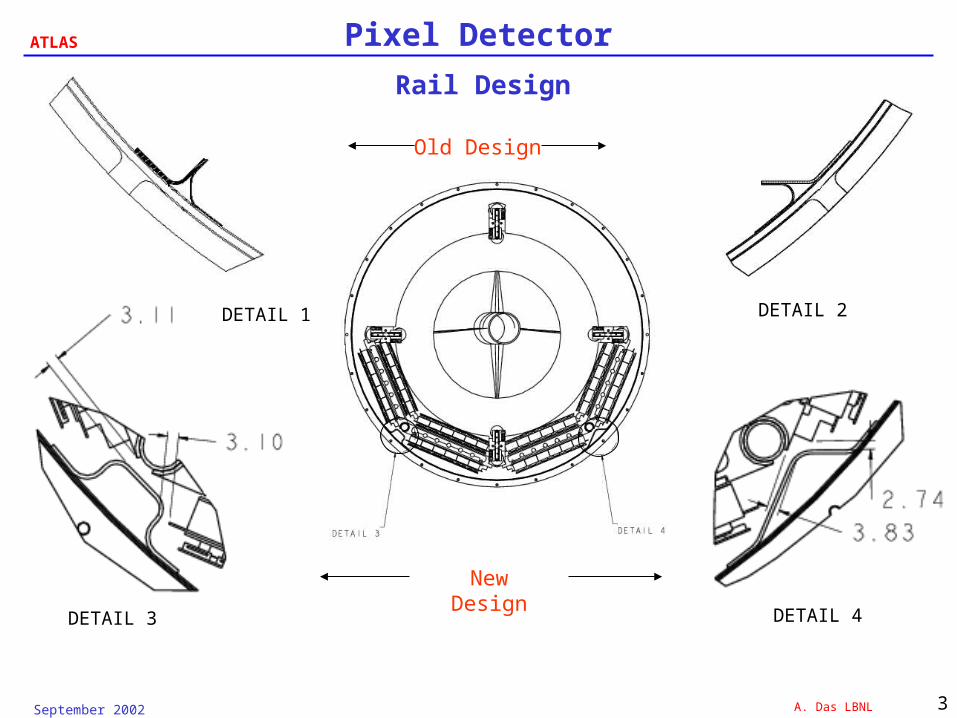
Rail Design
DETAIL 4DETAIL 3
DETAIL 1
Old Design
New Design
DETAIL 2

September 2002 A. Das LBNL 4
ATLAS Pixel Detector
Rail Tools
311.00
Flat Rail V-Rail
Cross Sections
Aluminum Tools
•CTE = 22.95 ppm/K
Cut By Wire EDM
•Length of 12.25 in. (311mm)
•Wire EDM is cheap, but surface is poor, so
Tooltec release film was used
Actual Rails 2.5 m in length
September 2002 A. Das LBNL 5
ATLAS Pixel Detector
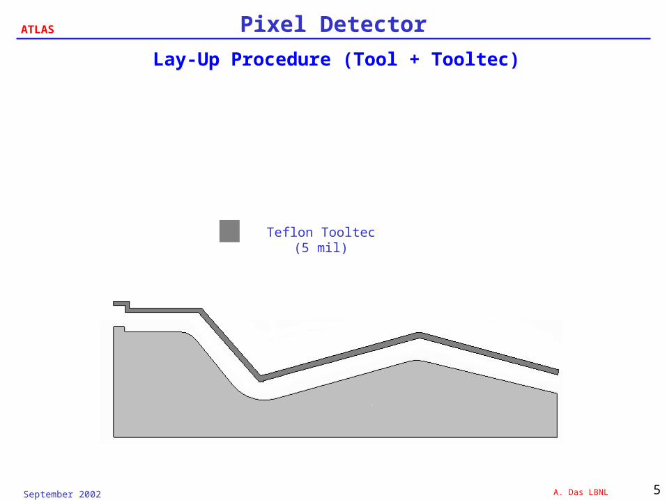
Lay-Up Procedure (Tool + Tooltec)
Teflon Tooltec (5 mil)

September 2002 A. Das LBNL 6
ATLAS Pixel Detector
Lay-Up Procedure (Tool + Tooltec +Mat)
17 gsm Prepreg Reinforced Mat (10 mil)
Teflon Tooltec (5 mil)

September 2002 A. Das LBNL 7
ATLAS Pixel Detector
Lay-Up Procedure (All Layers)
8 Plies P-30 Cloth (1 mm total thickness)
17 gsm Prepreg Reinforced Mat (10 mil)
Teflon Tooltec (5 mil)

September 2002 A. Das LBNL 8
ATLAS Pixel Detector
Prototype Parts
• High Strength Carbon Fiber Cloth– The cloth is 1K tow square weave, and the resin is EX1515, 125 gsm, 5 mil thickness– Cloth has lower stiffness than the YSH-80• Print-Through– Print-through was a problem on the initial parts, the rough fiber structure on the top of lay-up was pushed
through to the smooth side by the pressure during the curing cycle.– Since no additional resin dams were laid down and perforated A4000R was used as the release ply during
cure, much resin bled through to the surrounding bag and breather material. It was believed that the print-through was caused by the lack of resin within the part.
– Resin dams were laid down on second set of prototypes and non-perforated A4000R was used with the result that the tool side was much smoother, proving hypothesis correct.
• Tool Part Interaction– Another possible problem is the tool part interaction associated with the difference in CTE’s between the
aluminum tool and the part.– Tool Part Interaction can cause the part to “bow” in the cross-sectional and or longitudinal direction
September 2002 A. Das LBNL 9
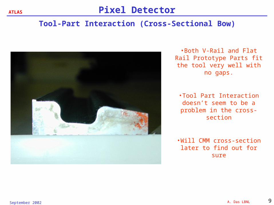
ATLAS Pixel DetectorTool-Part Interaction (Cross-Sectional Bow)
•Both V-Rail and Flat Rail Prototype Parts fit the tool
very well with no gaps.
•Tool Part Interaction doesn’t seem to be a problem in the
cross-section
•Will CMM cross-section later to find out for sure
September 2002 A. Das LBNL 10
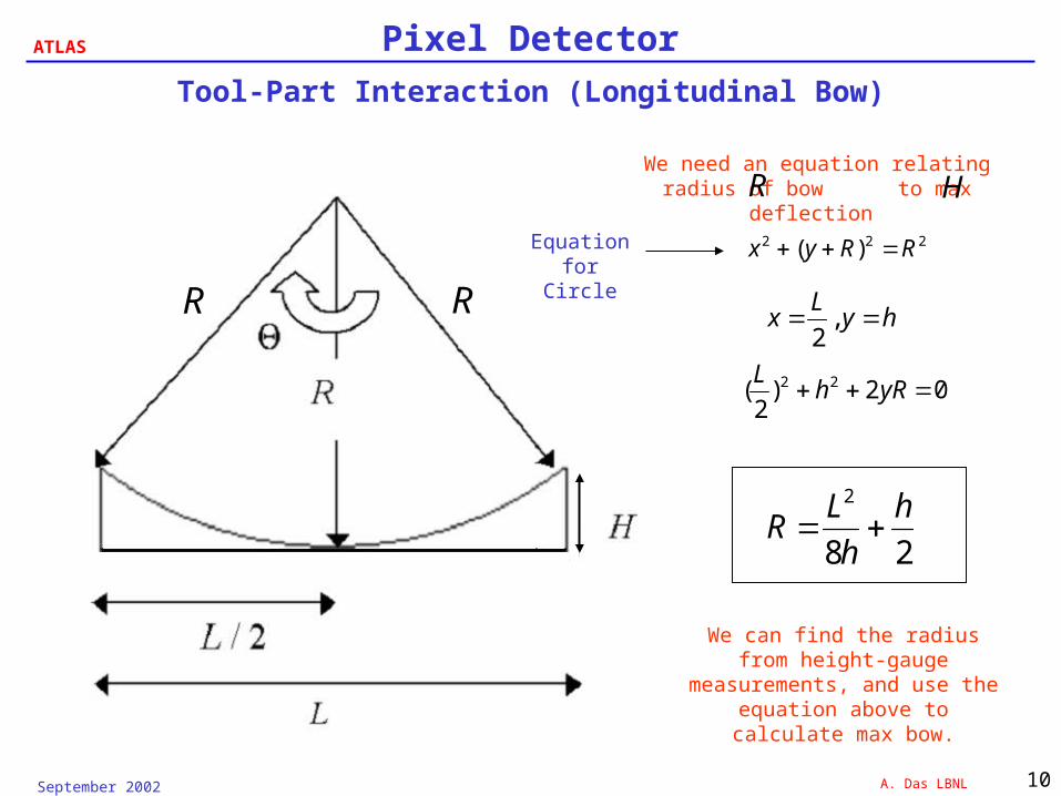
ATLAS Pixel DetectorTool-Part Interaction (Longitudinal Bow)
R R
222 )( RRyx
hyL
x ,2
02)2( 22 yRhL
28
2 h
h
LR
We need an equation relating radius of bow to max deflection HR
We can find the radius from height-gauge measurements, and use the equation above to
calculate max bow.
Equation for Circle
September 2002 A. Das LBNL 11
ATLAS Pixel DetectorWorst-Case Longitudinal Bow
Second Flat-Rail Prototype
-1
0
1
2
3
4
5
6
7
8
9
-8 -6 -4 -2 0 2 4 6 8
Distance along length (in.)
Var
iati
on
in
hei
gh
t (m
il)
Measured
Best-Fit, R=2,352 in.
Second V-Rail Prototype
-1
0
1
2
3
4
5
6
-8 -6 -4 -2 0 2 4 6 8
Distance along length (in)
Var
iati
on
in
hei
gh
t (m
il)
Measured
Best Fit, R=3,451 in.
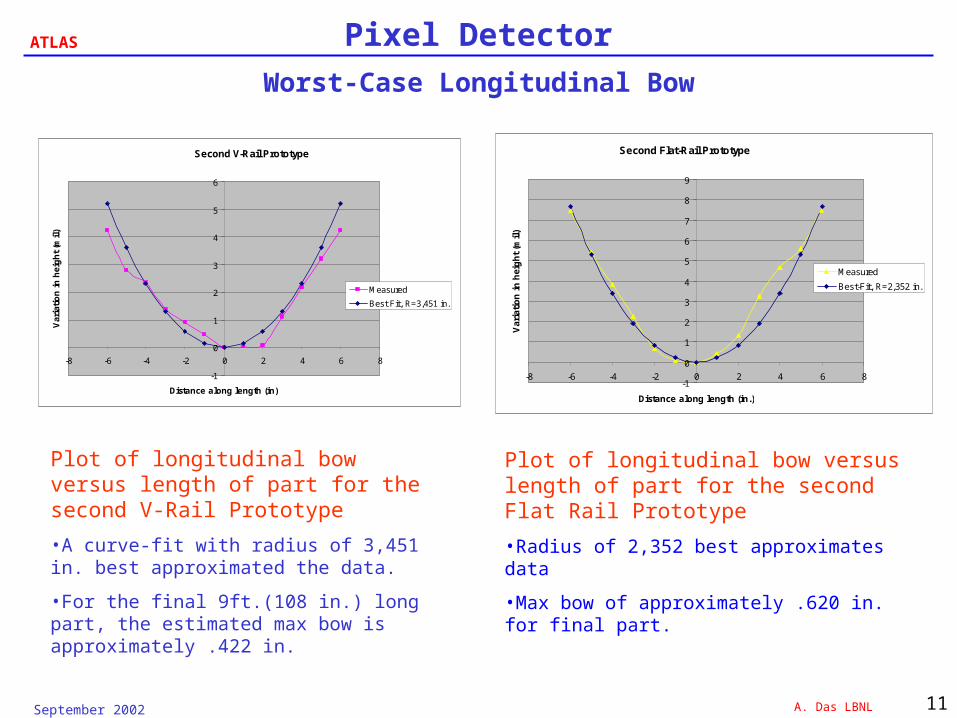
Plot of longitudinal bow versus length of part for the second V-Rail Prototype
•A curve-fit with radius of 3,451 in. best approximated the data.
•For the final 9ft.(108 in.) long part, the estimated max bow is approximately .422 in.
Plot of longitudinal bow versus length of part for the second Flat Rail Prototype
•Radius of 2,352 best approximates data
•Max bow of approximately .620 in. for final part.
September 2002 A. Das LBNL 12
ATLAS Pixel Detector
Conclusions
• Preliminary measurements using a height-gauge on prototype parts show that a worst-case bow of approximately .620 in. is expected on the final 2.5 m long rail
• There are three ways to compensate for the longitudinal bow caused by Tool Part Interaction in the final part.
I. A Reverse-Bow can be machined in the tool itself to compensate
II. The “bowed” part can be bonded to the PST so that it lies correctly.
III. In the future, steel tools with much lower CTE will be used in place of aluminum to minimize the effects of tool part interaction.