basic mechanical design - urząd miasta Łodzicybra.p.lodz.pl/content/2319/mech_design.pdf · the...
TRANSCRIPT
THE UNIVERSITY OF TECHNOLOGY IN LODZ
BASIC MECHANICAL DESIGN
[Standard Extracts And Other Materials]
Zbigniew Zdziennicki [2008]
[The booklet contains useful materials for Mechanical Engineering Design and Workshop subject for students of International Faculty of Engineering]
2
CONTENTS
Part I STANDARD EXTRACTS Metric trapezoidal threads…………………………………………….. 3 – 4 Recommended tolerance for trapezoidal thread……………………... 5 Lip seals…………………………………………………………………. 6 Shaft lifts of gear reducers……………………………………………... 7 Recommended diameters for journals of shaft ends…………………. 8 Recommended gear ratios……………………………………………… 9 Surface quality according PN-EN ISO 1302:2004……………………. 9 Retaining rings.......................................................................................... 10 – 11 Hexagon headed bolts.…………………………………………………. 12 – 13 Square-head machine bolts……………………………………………. 14 Socket head bolts……………………………………………………….. 15 Stud bolts………………………………………………………………... 16 Standard hex nuts………………………………………………………. 17 Hex jam nuts……………………………………………………………. 18 Spring lock washers……………………………………………………. 19 Parallel keys............................................................................................. 20 Shoulders with relief groove…………………………………………… 21 Part II OTHER MATERIALS Preferred metric sizes…………………………………………………... 22 Recommended fit systems and diameter series.... ………………….…. 23 Installation of components on drive shafts…………………………… 24 Mounting arrangements of a pulley or a sprocket………………….… 25 Chamfers………………………………………………………………… 25 Cap of a screw jack – main dimensions.................................................. 26 Alternative designs of the cap.................................................................. 26 Ball knobs with collar…………………………………………………... 27 Centre holes with thread……………………………………………….. 27 Drain plug.................................................................................................. 28 Breathers.................................................................................................... 28 Guide date for dimensions of gear cases………………………….…… 29 Caps for bearing housings……………………………………………... 30 Distance rings and sleeve for shafts…………………………………… 31 Distance rings and sleeve for housings………………………………… 32 Young’s moduli for various metals……………………………………. 33 Poisson’s ratios for various metals……………………………………. 33 Recommended journals of shaft ends – cylindrical ones…..………… 34 Dimensions of keyseats…………………………………………………. 35 Relation of hardness numbers…………………………………………. 36 Recommended number of pinion teeth according to Niemann……… 37 Spur gear design formulas……………………………………………... 37 Length Excesses Recommended for Threads........................................ 38 Casting Rib Design................................................................................... 39

3
METRIC TRAPEZOIDAL THREADS PN – ISO 2904: 1996
Thread Size
Diameter mm
Pitch mm
Major Dia of Nut, Dr
mm
Major Dia ofScrew, d
mm
Pitch Dia of Thread, Dp=dp
mm
Minor Dia of Nut, D
mm
Minor Dia ofScrew, dr
mm 1 2 3 4 5 6 7 8 1.5 8.30 8.00 7.25 6.50 6.20 9 1.5
2 9.30 9.50
9.00 9.00
8.25 8.00
7.50 7.00
7.20 6.50
10 1.5 2
10.30 10.50
10.00 10.00
9.25 9.00
8.50 8.00
8.20 7.50
11 2 3
11.50 11.50
11.00 11.00
10.00 9.50
9.00 8.00
8.50 7.50
12 2 3
12.50 12.50
12.00 12.00
11.00 10.50
10.00 9.00
9.50 8.50
14 2 3
14.50 14.50
14.00 14.00
13.00 12.50
12.00 11.00
11.50 10.50
16 2 4
16.50 16.50
16.00 16.00
15.00 14.00
14.00 12.00
13.50 11.50
18 2 4
18.50 18.50
18.00 18.00
17.00 16.00
16.00 14.00
15.50 13.50
20 2 4
20.50 20.50
20.00 20.00
19.00 18.00
18.00 16.00
17.50 15.50
22
3 5 8
22.50 22.50 23.00
22.00 22.00 22.00
20.50 19.50 18.00
19.00 17.00 14.00
18.50 16.50 13.00
24
3 5 8
24.50 24.50 25.00
24.00 24.00 24.00
22.50 21.50 20.00
21.00 19.00 16.00
20.50 18.50 15.00
26
3 5 8
26.50 26.50 27.00
26.00 26.00 26.00
24.50 23.50 22.00
23.00 21.00 18.00
22.50 20.50 17.00
28
3 5 8
28.50 28.50 29.00
28.00 28.00 28.00
26.50 25.50 24.00
25.00 23.00 20.00
24.50 22.50 19.00
30
3 6
10
30.50 31.00 31.00
30.00 30.00 30.00
28.50 27.00 25.00
27.00 24.00 20.00
26.50 23.00 19.00
32
3 6
10
32.50 33.00 33.00
32.00 32.00 32.00
30,50 29.00 27.00
29.00 26.00 22.00
28.50 25.00 21.00

4
METRIC TRAPEZOIDAL THREADS cont. PN – ISO 2904: 1996
Thread Size Diameter
mm
Pitch mm
Major Dia of Nut, Dr
mm
Major Dia ofScrew, d
mm
Pitch Dia of Thread, Dp=dp
mm
Minor Dia of Nut, D
mm
Minor Dia ofScrew, dr
mm 1 2 3 4 5 6 7
34 3 6
10
34.50 35.00 35.00
34.00 34.00 34.00
32.50 31.00 29.00
31.00 28.00 24.00
30.50 27.00 23.00
36
3 6
10
36.50 37.00 37.00
36.00 36.00 36.00
34.50 33.00 31.00
33.00 30.00 26.00
32.50 29.00 25.00
38
3 7
10
38.50 39.00 39.00
38.00 38.00 38.00
36.50 34.50 33.00
35.00 31.00 28.00
34.50 30.00 27.00
40
3 7
10
40.50 41.00 41.00
40.00 40.00 40.00
38.50 36.50 35.00
37.00 33.00 30.00
36.50 32.00 29.00
42
3 7
10
42.50 43.00 43.00
42.00 42.00 42.00
40.50 38.50 37.00
39.00 35.00 32.00
38.50 34.00 31.00
44
3 7
12
44.50 45.00 45.00
44.00 44.00 44.00
42.50 40.50 38.00
41.00 37.00 32.00
40.50 36.00 31.00
46
3 8
12
46.50 47.00 47.00
46.00 46.00 46.00
44.50 42.00 40.00
43.00 38.00 34.00
42.50 37.00 33.00
48
3 8
12
48.50 49.00 49.00
48.00 48.00 48.00
46.50 44.00 42.00
45.00 40.00 36.00
44.50 39.00 35.00
50
3 8
12
52.50 51.00 51.00
50.00 50.00 50.00
48.50 46.00 44.00
47.00 42.00 38.00
46.50 41.00 37.00
52
3 8
12
52.50 53.00 53.00
52.00 52.00 52.00
50.50 48.00 46.00
49.00 44.00 40.00
48.50 43.00 39.00
55
3 9
14
55.50 56.00 57.00
55.00 55.00 55.00
53.50 50.50 48.00
52.00 46.00 41.00
51.50 45.00 39.00
60
3 9
14
60.50 61.00 62.00
60.00 60.00 60.00
58.50 55.50 53.00
57.00 51.00 46.00
56.50 50.00 44.00
5
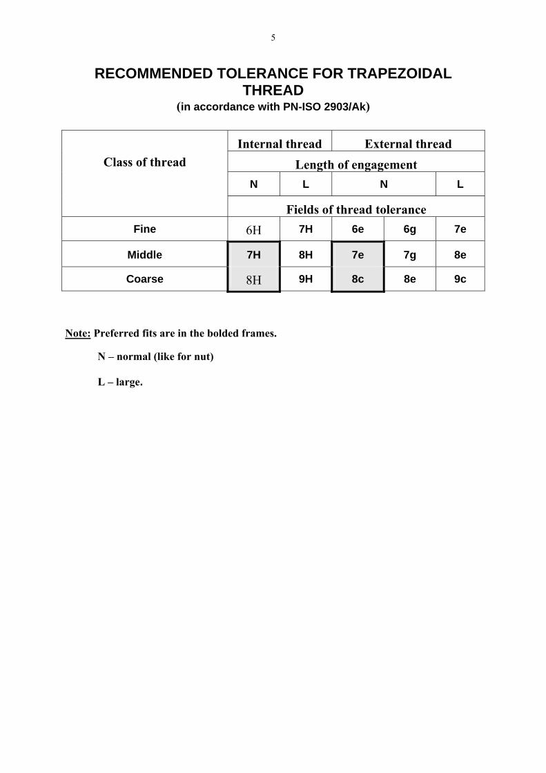
RECOMMENDED TOLERANCE FOR TRAPEZOIDAL THREAD
(in accordance with PN-ISO 2903/Ak)
Internal thread External thread Length of engagement
N L N L
Class of thread
Fields of thread tolerance Fine 6H 7H 6e 6g 7e
Middle 7H 8H 7e 7g 8e
Coarse 8H 9H 8c 8e 9c
Note: Preferred fits are in the bolded frames.
N – normal (like for nut) L – large.

6
LIP SEALS PN-72/M-86964
Designation of a radial oil seal that is A kind and possesses: inside diameter (diameter of the shaft) d = 30 mm, outside diameter D = 50 mm, height b = 10 mm:
LIP SEAL A 30x50x10 PN-72/M-86964
D 35 40 (47) 50 (52) 55 (62) 65 70 72 75 80 85 90 100 110 120
d b 20 7 10 25 7 7 10 10 10 30 7 10 10 10 10 35 7 7 10 10 10 40 7 7 10 10 10 45 10 10 10 10 50 8 10 10 10 10 55 8 10 10 10 10 60 8 10 10 70 10 10 12 80 10 10 90 12 12 100 12
If the main purpose of the seal is to prevent lubricant from leaving the housing, the seal should be fitted with the lip facing inwards (see figure below).
7
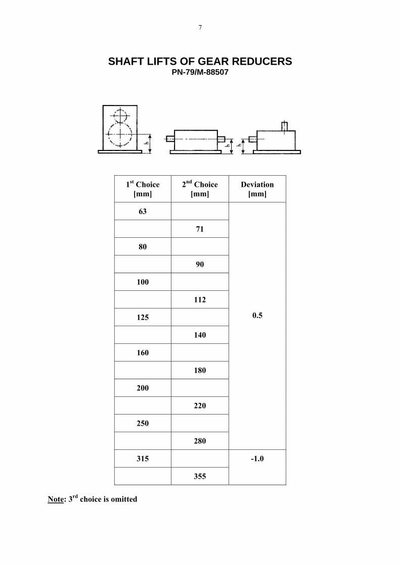
SHAFT LIFTS OF GEAR REDUCERS PN-79/M-88507
1st Choice
[mm] 2nd Choice
[mm] Deviation
[mm]
63
71
80
90
100
112
125
140
160
180
200
220
250
280
0.5
315
355
-1.0
Note: 3rd choice is omitted
8
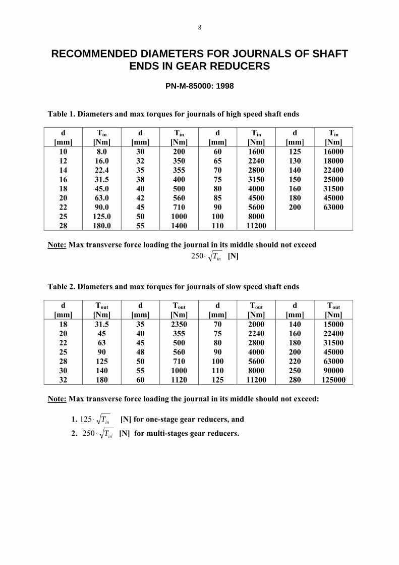
RECOMMENDED DIAMETERS FOR JOURNALS OF SHAFT ENDS IN GEAR REDUCERS
PN-M-85000: 1998
Table 1. Diameters and max torques for journals of high speed shaft ends
d [mm]
Tin[Nm]
d [mm]
Tin[Nm]
d [mm]
Tin[Nm]
d [mm]
Tin[Nm]
10 12 14 16 18 20 22 25 28
8.0 16.0 22.4 31.5 45.0 63.0 90.0
125.0 180.0
30 32 35 38 40 42 45 50 55
200 350 355 400 500 560 710
1000 1400
60 65 70 75 80 85 90
100 110
1600 2240 2800 3150 4000 4500 5600 8000
11200
125 130 140 150 160 180 200
16000 18000 22400 25000 31500 45000 63000
Note: Max transverse force loading the journal in its middle should not exceed
inT⋅250 [N] Table 2. Diameters and max torques for journals of slow speed shaft ends
d [mm]
Tout[Nm]
d [mm]
Tout[Nm]
d [mm]
Tout[Nm]
d [mm]
Tout[Nm]
18 20 22 25 28 30 32
31.5 45 63 90
125 140 180
35 40 45 48 50 55 60
2350 355 500 560 710
1000 1120
70 75 80 90
100 110 125
2000 2240 2800 4000 5600 8000
11200
140 160 180 200 220 250 280
15000 22400 31500 45000 63000 90000
125000 Note: Max transverse force loading the journal in its middle should not exceed: 1. inT⋅125 [N] for one-stage gear reducers, and
2. inT⋅250 [N] for multi-stages gear reducers.

9
RECOMMENDED GEAR RATIOS
PN – 76/ M-88513
1st choice 2nd choice 1st choice 2nd choice 1st choice 2nd choice
1 — 2.5 — 6.3 —
— 1.12 — 2.8 — 7.1
1.25 — 3.15 — 8 —
— 1.4 — 3.55 — 9
1.6 — 4 — 10 —
— 1.8 — 4.5 — 11.2
2 — 5 — 12.5 —
— 2.24 — 5.6 — 14
SURFACE QUALITY ACCORDING PN – EN ISO 1302: 2004
Roughness [µ] Class Ra Rz Rt
Procedure
N1 0.025 0.3 0.6
N2 0.05 0.6 1
N3 0.1 1.1 1 Lapped/Polished
N4 0.2 1.8 1.6 Lapped/Polished
N5 0.4 2.8 2.5 Honed
N6 0.8 4.8 2.5 Ground
N7 1.6 8 4 Turned with diamond
N8 3.2 16 4 Milled
N9 6.3 32 8 Turned
N10 12.5 57 16
N11 25.0 110 16 Sawed
N12 50.0 220 25

10
RETAINING RINGS
PN-81/M-85111
d D0 D1 b g f h S[kN] 17 15.7 16.2 2.3 1.0 1.1 1.2 5.1 18 16.5 17.0 2.4 6.7 20 18.5 19.0 2.6 7.5 22 20.5 21.0 2.8
1.5
8.3 24 22.2 22.9 3.0 9.9 25 22.2+0.21 23.9 3.0 10.5 26 24.2-0.42 24.9 3.1
1.2
1.3 1.7
10.8 28 25.9 26.6 3.2 14.7 30 27.9 28.6 3.5
2.1 15.9
32 29.6 30.3 3.6 2.6 20.6 35 32.2+0.25 33.0 3.9
1.5
1.6 26.2
36 33.2+0.50 34.0 4.0 27.1 38 35.2 36.0 4.2
3.0
28.5 40 36.5 37.5 4.4 37.3 42 38.5+0.39 39.5 4.5 39.2 45 41.5-0.78 42.5 4.7 42.1 48 44.5 45.5 5.0
1.75
1.85
3.8 45.1
50 45.8 47 5.1 55.9 55 50.8 52 5.4 61.7 56 51.8 53 5.5 62.7 60 55.8+0.46 57 5.8 67.6 63 58.8-0.92 60 6.2
2.0
2.15
68.8 65 60.8 62 6.3 73.5 70 65.5 67 6.6 78.9 72 67.5 69 6.8 81.3 75 70.5 72 7.0
2.5
2.65
4.5
84.3 S = Max axial force loading the retaining ring

11
RETAINING RINGS Cont.
PN-81/M-85111
d D0 D1 b g F h S[kN] 37 39.8+0.50 39.0 3.6 26.6 38 40.8-0.25 40.0 3.7
1.5
1.6
3.0 27.6
40 43.5+0.78 42.5 3.9 39.7 42 45.5-0.39 44.5 4.1 41.7 45 48.5 47.5 4.3 42.2 47 50.5 49.5 4.4 42.7 48 51.5 50.5 4.5
1.75
1.85
3.8
42.9 50 54.2 53 4.6 59.5 55 59.2 58 5.0 62.2 56 60.2+0.92 59 5.1 59.5 60 64.2-0.46 63 5.4 60.9 62 66.2 65 5.5 60.5 63 67.2 66 5.6
2.0
2.15
60.4 65 69.2 68 5.8 76.6 70 74.5 73 6.2 82.5 75 79.5 78 6.6
4.5
88.2 80 85.5 83.5 7.0
2.5
2.65 109.8
85 90.5 88.5 7.2 116.6 88 93.5+1.08 91.5 7.4 120.5 90 95.5-0.54 93.5 7.6 123.5
100 105.5 104 8.4
3.0
3.15
5.3
137.2 105 112 109 8.7 164.6 110 117 114 9.0 172.5 120 127 124 9.7 188.2 130 137+1.26 134 10.2 102.9 140 147-0.63 144 10.7
4.0
4.15
6.0
118.5 S = Max axial force loading the retaining ring

12
HEXAGON HEADED BOLTS
PN-EN ISO 4014: 2004
This is only part of the tabulation in the Standard.

13
HEXAGON HEADED BOLTS
PN-EN ISO 4017: 2004
This is only part of the tabulation in the Standard.

14
SQUARE-HEAD MACHINE BOLTS
PN-86/K-80005
This is only part of the tabulation in the Standard.

15
SOCKET HEAD BOLTS
PN-EN ISO 4762: 2001
This is only part of the tabulation in the Standard.
16
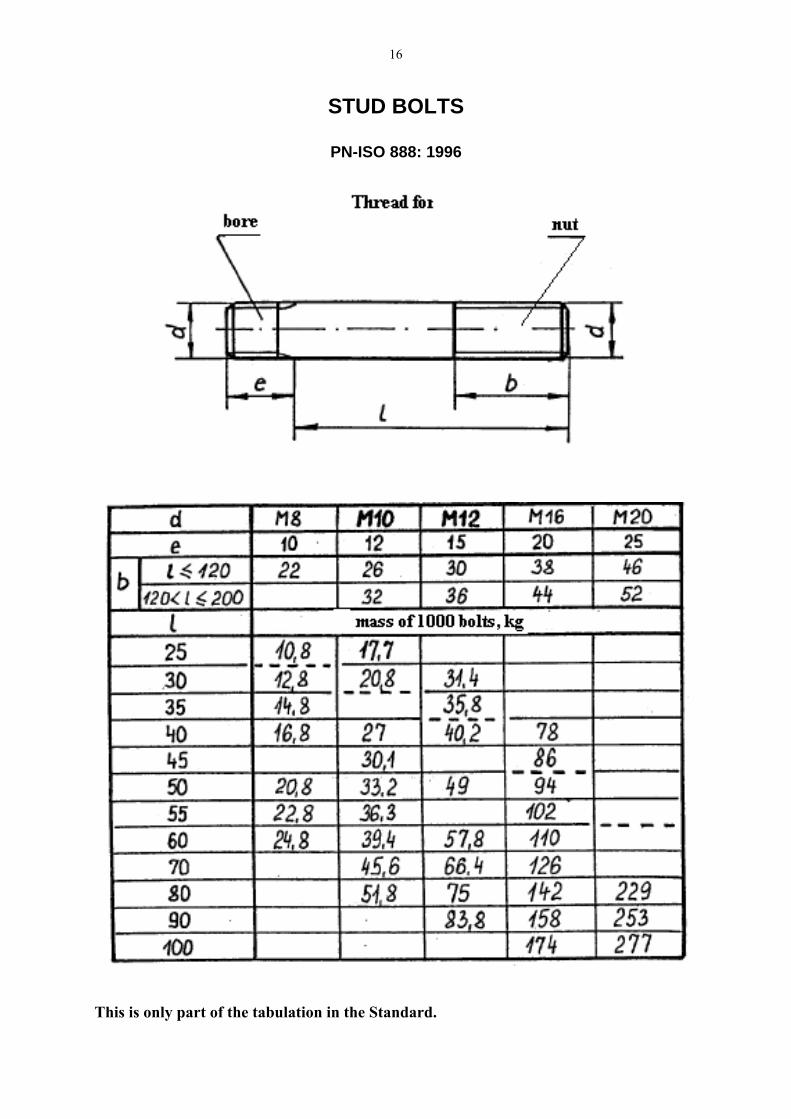
STUD BOLTS
PN-ISO 888: 1996
This is only part of the tabulation in the Standard.

17
STANDARD HEX NUTS
PN-EN ISO 4032: 2004
This is only part of the tabulation in the Standard.

18
HEX JAM NUTS
PN-EN ISO 4035: 2004
This is only part of the tabulation in the Standard.
19
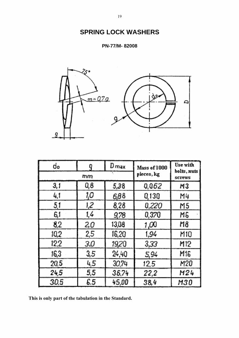
SPRING LOCK WASHERS
PN-77/M- 82008
This is only part of the tabulation in the Standard.
20
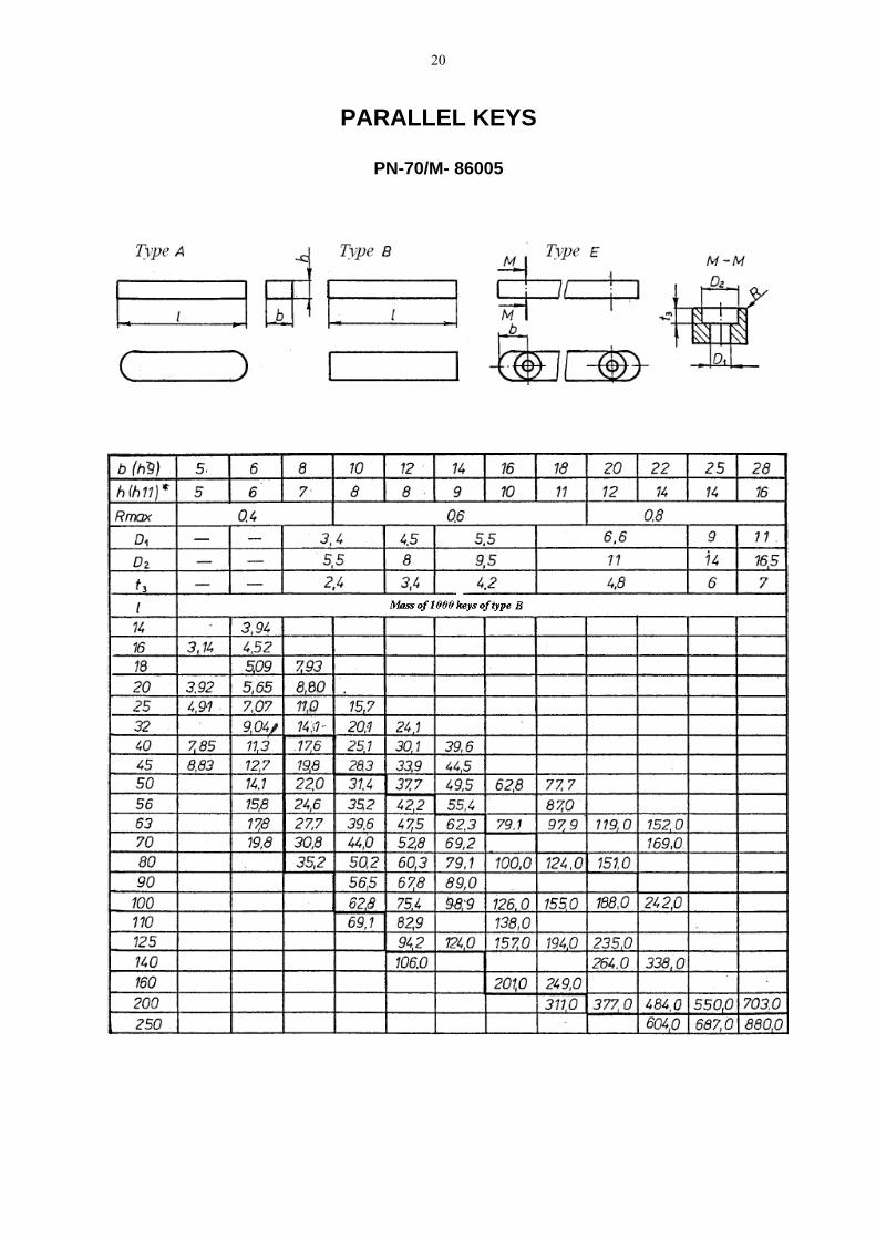
PARALLEL KEYS
PN-70/M- 86005
21
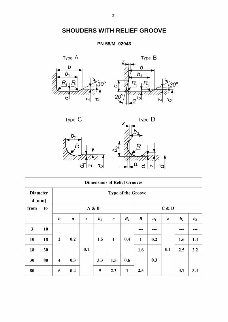
SHOUDERS WITH RELIEF GROOVE
PN-58/M- 02043
Dimensions of Relief Grooves
Diameter
d [mm]
Type of the Groove
A & B C & D from to
b a z b1 c R1 R a1 z b2 b3
3 10 --- --- --- ---
10 18 1 0.2 1.6 1.4
18 30
2
0.2
1.5
1
0.4
1.6 2.5 2.2
30 80 4 0.3 3.3 1.5 0.6
80 ---- 6 0.4
0.1
5 2.3 1
2.5
0.3
0.1
3.7
3.4
22
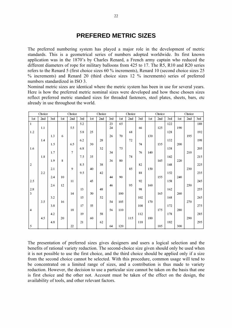
PREFERED METRIC SIZES
The preferred numbering system has played a major role in the development of metric standards. This is a geometrical series of numbers adopted worldwide. Its first known application was in the 1870’s by Charles Renard, a French army captain who reduced the different diameters of rope for military balloons from 425 to 17. The R5, R10 and R20 series refers to the Renard 5 (first choice sizes 60 % increments), Renard 10 (second choice sizes 25 % increments) and Renard 20 (third choice sizes 12 % increments) series of preferred numbers standardized in ISO 3. Nominal metric sizes are identical where the metric system has been in use for several years. Here is how the preferred metric nominal sizes were developed and how these chosen sizes reflect preferred metric standard sizes for threaded fasteners, steel plates, sheets, bars, etc already in use throughout the world.
The presentation of preferred sizes gives designers and users a logical selection and the benefits of rational variety reduction. The second-choice size given should only be used when it is not possible to use the first choice, and the third choice should be applied only if a size from the second choice cannot be selected. With this procedure, common usage will tend to be concentrated on a limited range of sizes, and a contribution is thus made to variety reduction. However, the decision to use a particular size cannot be taken on the basis that one is first choice and the other not. Account must be taken of the effect on the design, the availability of tools, and other relevant factors.

23
RECOMMENDED FIT SYSTEMS & DIAMETER SERIES 1. TOLERANCES IN ACCORDANCE WITH PN-EN 20286-2:1996 STANDARD Fits of hole basis system
H11/d11 Easy running fit H7/f7, H8/f9 Running fit
Clearance
H8/h8 Slide fit H8/js7 Push fit H7/k6 Light keying fit
Transition
H7/n6 Heavy keying fit H7/p6 Very light drive fit
Close H7/s7 Drive fit
Fits of shaft basis system D11/h11 Easy running fit
Clearance F9/h8 Running fit U8/h7 Very heavy drive fit 1
Close Z8/h7 Very heavy drive fit 5
2. FIT SYSTEM FOR ROLLING BEARING H7/js6 H7/k6 For rotational shaft
K7/h6 N7/h6 For rotational housing
H8/h8 With adapter sleeve
Notice: The fit systems do not concern keys, taper keys, pins. Fits:
U8/h7 Steel on steel (cool) Z8/h7 Cast iron on steel (cool) Z8/h7 Steel on steel (hot)
3. DIAMETERS Hub diameters of gears, sprockets, pulleys in accordance with their bores,
approximately: Bore 10 (12) (15) (18) 20 (22) 25 30 35 40 45 50 60 65 Hub 20 (25) (30) (36) 36 (40) 45 55 60 70 75 80 100 105 Bore 80 90 100 Hub 120 130 150
Diameters of shafts, journals & pins
6, 8, 10, 12, (14), (15), 16, (17), (18), 20, (22), 25, (28), 30, (32), 35, 40, 50, 55, 60, 65, 70, 75, 80, (85), 90, (95), 100, (105), 110, (115), 120, 125.
3.3. Bores
6, 8, 10, 12, (14), (15), 16, (18), 20, (22), 25, (28), 30, 32, 35, (38) 40, 42, (45), 47 50, (52), 55, 60, (65), (68) (70), (72), 75, 80, (85), 90, (95), 100, (105), 110, (115), 120, (125), 130, 140, 150, (160), (180), (190), (195), 200, (210), 220, (230).
( ) – not recommended
24
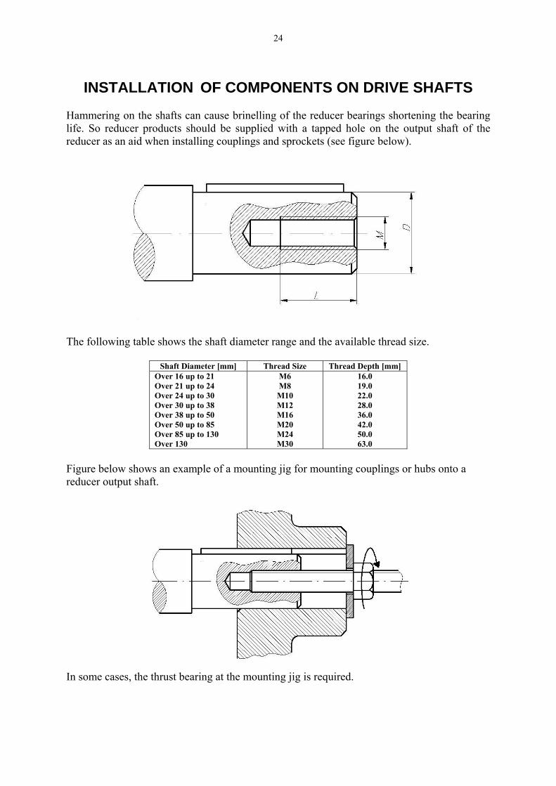
INSTALLATION OF COMPONENTS ON DRIVE SHAFTS
Hammering on the shafts can cause brinelling of the reducer bearings shortening the bearing life. So reducer products should be supplied with a tapped hole on the output shaft of the reducer as an aid when installing couplings and sprockets (see figure below).
The following table shows the shaft diameter range and the available thread size.
Shaft Diameter [mm] Thread Size Thread Depth [mm] Over 16 up to 21 Over 21 up to 24 Over 24 up to 30 Over 30 up to 38 Over 38 up to 50 Over 50 up to 85 Over 85 up to 130 Over 130
M6 M8 M10 M12 M16 M20 M24 M30
16.0 19.0 22.0 28.0 36.0 42.0 50.0 63.0
Figure below shows an example of a mounting jig for mounting couplings or hubs onto a reducer output shaft.
In some cases, the thrust bearing at the mounting jig is required.
25
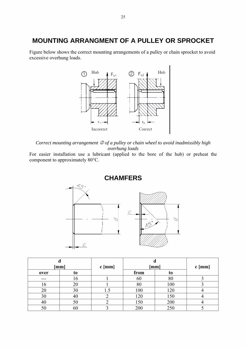
MOUNTING ARRANGMENT OF A PULLEY OR SPROCKET
Figure below shows the correct mounting arrangements of a pulley or chain sprocket to avoid excessive overhung loads.
Correct mounting arrangement of a pulley or chain wheel to avoid inadmissibly high overhung loads
For easier installation use a lubricant (applied to the bore of the hub) or preheat the component to approximately 80°C.
CHAMFERS
d [mm]
d [mm]
over to
c [mm]
from to
c [mm]
--- 16 1 60 80 3 16 20 1 80 100 3 20 30 1.5 100 120 4 30 40 2 120 150 4 40 50 2 150 200 4 50 60 3 200 250 5

26
CAP OF A SCREW JACK – MAIN DIMENSIONS
.
ALTERNATIVE DESIGNS OF THE JACK CAP
27
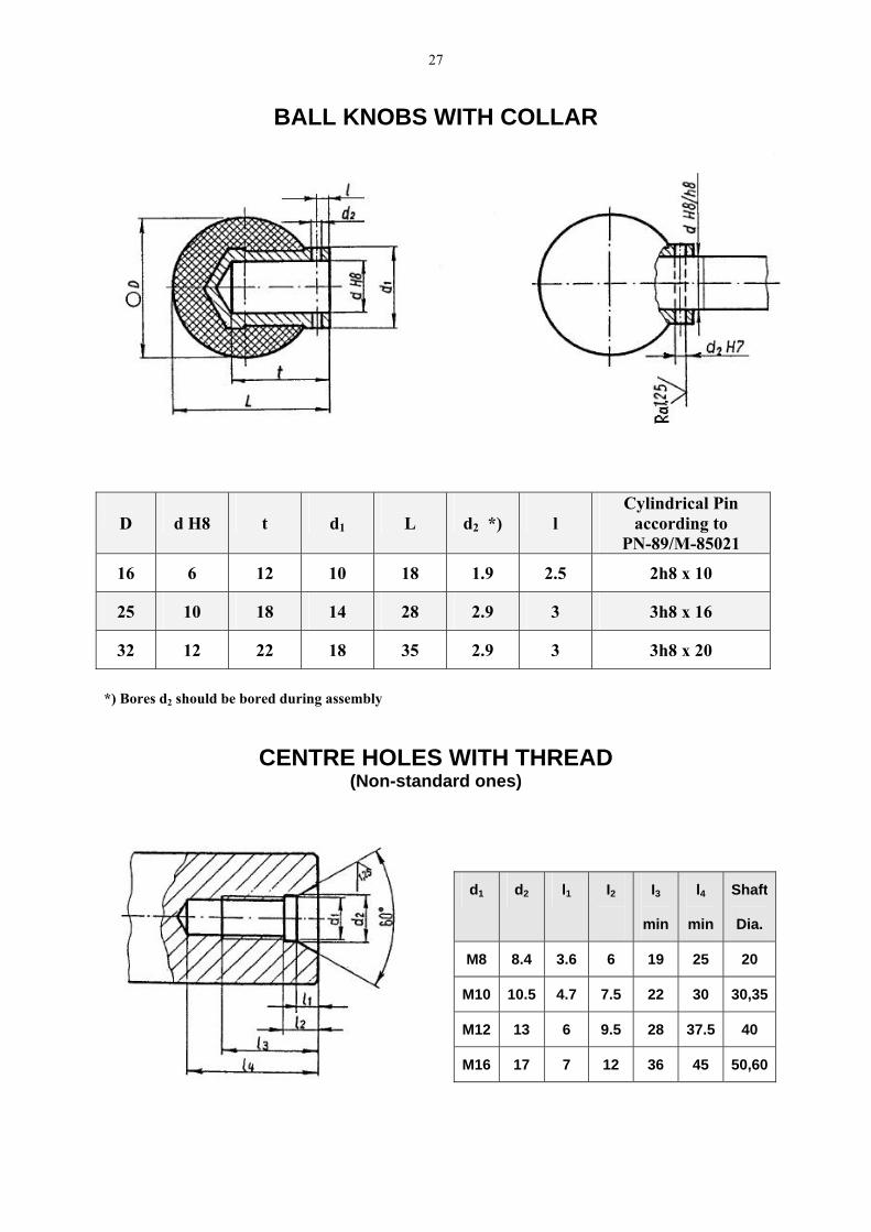
BALL KNOBS WITH COLLAR
D
d H8
t
d1
L
d2 *)
l
Cylindrical Pin according to
PN-89/M-85021
16 6 12 10 18 1.9 2.5 2h8 x 10
25 10 18 14 28 2.9 3 3h8 x 16
32 12 22 18 35 2.9 3 3h8 x 20
*) Bores d2 should be bored during assembly
CENTRE HOLES WITH THREAD (Non-standard ones)
d1 d2 l1 I2
I3
min
l4
min
Shaft
Dia.
M8 8.4 3.6 6 19 25 20
M10 10.5 4.7 7.5 22 30 30,35
M12 13 6 9.5 28 37.5 40
M16 17 7 12 36 45 50,60

28
DRAIN PLUG
BREATHERS
Alternative design A
Alternative design B
29
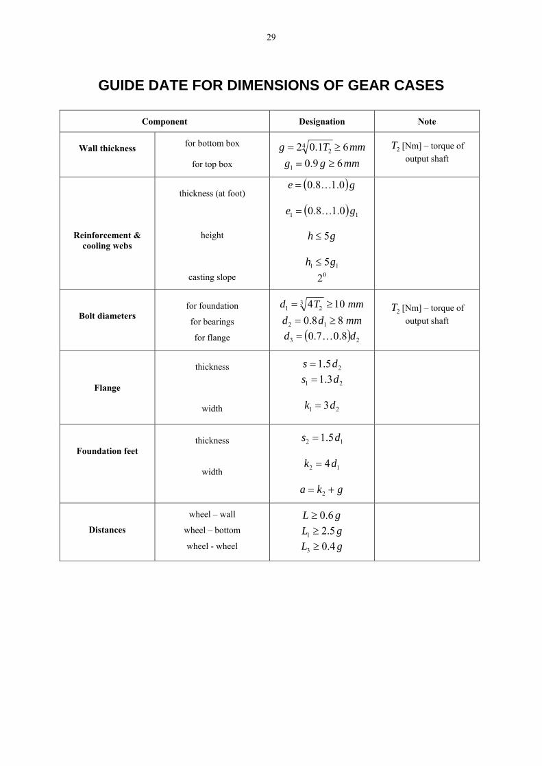
GUIDE DATE FOR DIMENSIONS OF GEAR CASES
Component Designation Note
Wall thickness for bottom box
for top box
mmTg 61.0242 ≥=
mmgg 69.01 ≥=
2T [Nm] – torque of output shaft
Reinforcement & cooling webs
thickness (at foot)
height
casting slope
( )ge 0.18.0 K=
( ) 11 0.18.0 ge K=
gh 5≤
11 5gh ≤ 02
Bolt diameters for foundation
for bearings
for flange
mmTd 104321 ≥=
mmdd 88.0 12 ≥=
( ) 23 8.07.0 dd K=
2T [Nm] – torque of output shaft
Flange
thickness
width
25.1 ds =
21 3.1 ds =
21 3dk =
Foundation feet
thickness
width
12 5.1 ds =
12 4dk =
gka += 2
Distances
wheel – wall
wheel – bottom
wheel - wheel
gL 6.0≥
gL 5.21 ≥
gL 4.03 ≥
30
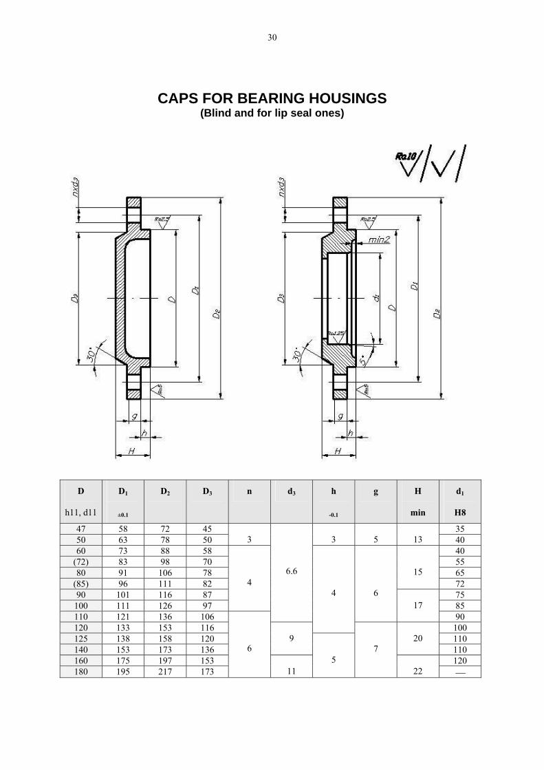
CAPS FOR BEARING HOUSINGS (Blind and for lip seal ones)
D
h11, d11
D1
±0.1
D2 D3 n d3 h
-0.1
g H
min
d1
H8
47 58 72 45 35 50 63 78 50
3
3
5
13 40
60 73 88 58 40 (72) 83 98 70 55 80 91 106 78 65
(85) 96 111 82
15 72
90 101 116 87 75 100 111 126 97
4
85 110 121 136 106
6.6
6 17
90 120 133 153 116
4
100 125 138 158 120 110 140 153 173 136
9
20
110 160 175 197 153 120 180 195 217 173
6
11
5
7
22 ⎯
31
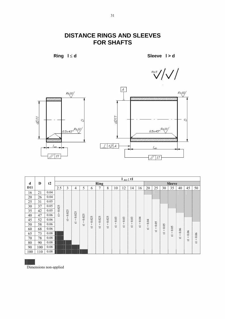
DISTANCE RINGS AND SLEEVES
FOR SHAFTS
Ring l ≤ d Sleeve l > d
l -0.1 ; t1 Ring Sleeve
d
D11
D
t2
2.5 3 4 5 6 7 8 10 12 14 16 20 25 30 35 40 45 50 16 21 0.04
20 26 0.04
25 31 0.05
30 37 0.05
35 42 0.05
40 47 0.06
45 52 0.06
50 58 0.06 60 68 0.06
t1=
0.02
5
65 73 0.08 70 78 0.08
t1=
0.02
5
80 90 0.08
t1 =
0.0
25
90 100 0.08
t1 =
0.0
25
100 110 0.08
t1 =
0.0
25
t1 =
0.0
25
t1 =
0.0
25
t1 =
0.0
3
t1 =
0.0
3
t1 =
0.0
3
t1 =
0.0
4
t1 =
0.0
4
t1 =
0.0
5
t1 =
0.0
5
t1 =
0.0
5
t1 =
0.0
6
t1 =
0.0
6
t1 =
0.0
6
Dimensions non-applied
32
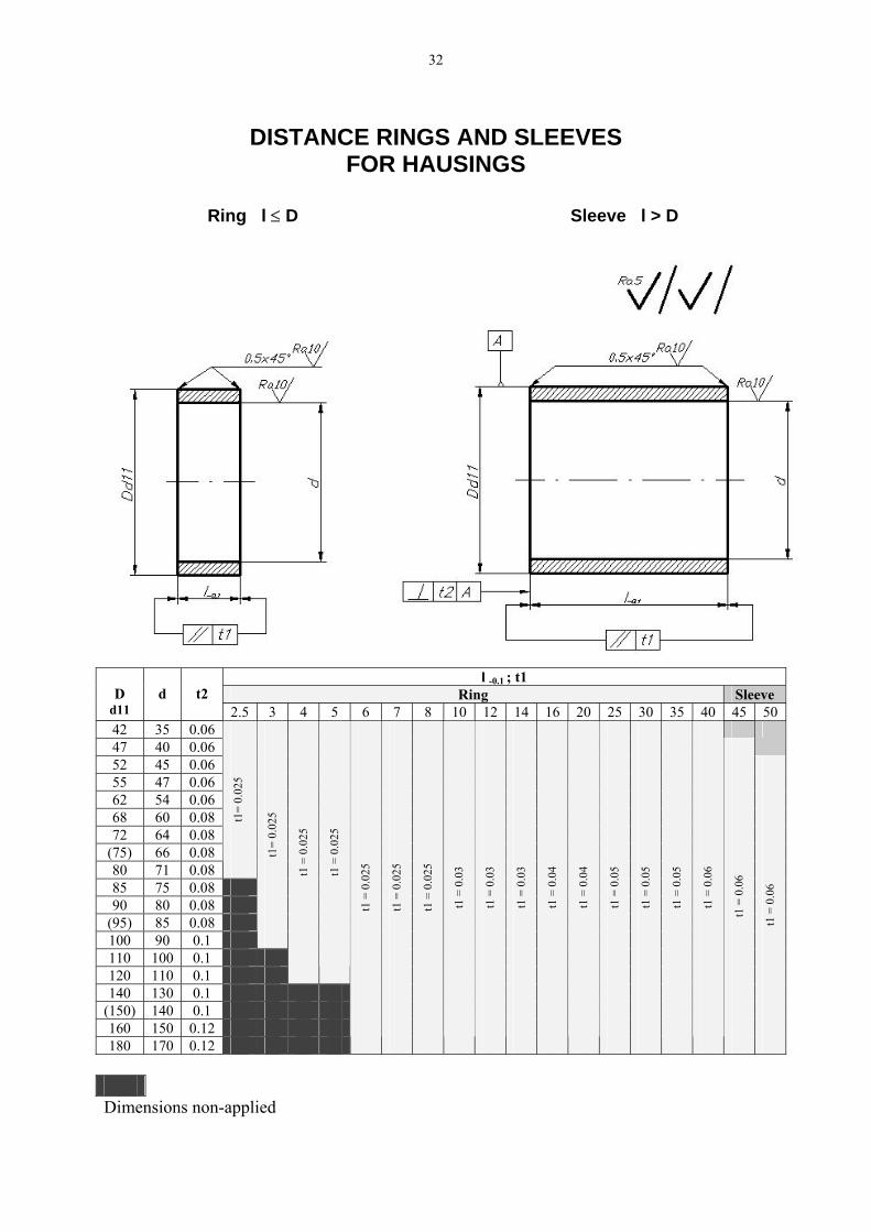
DISTANCE RINGS AND SLEEVES
FOR HAUSINGS
Ring l ≤ D Sleeve l > D
l -0.1 ; t1
Ring Sleeve
D d11
d
t2
2.5 3 4 5 6 7 8 10 12 14 16 20 25 30 35 40 45 50 42 35 0.06 47 40 0.06
52 45 0.06 55 47 0.06 62 54 0.06 68 60 0.08 72 64 0.08
(75) 66 0.08 80 71 0.08
t1=
0.02
5
85 75 0.08 90 80 0.08
(95) 85 0.08 100 90 0.1
t1=
0.02
5
110 100 0.1 120 110 0.1
t1 =
0.0
25
t1 =
0.0
25
140 130 0.1 (150) 140 0.1 160 150 0.12 180 170 0.12
t1 =
0.0
25
t1 =
0.0
25
t1 =
0.0
25
t1 =
0.0
3
t1 =
0.0
3
t1 =
0.0
3
t1 =
0.0
4
t1 =
0.0
4
t1 =
0.0
5
t1 =
0.0
5
t1 =
0.0
5
t1 =
0.0
6
t1 =
0.0
6
t1 =
0.0
6
Dimensions non-applied
33
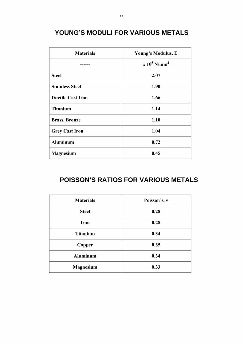
YOUNG’S MODULI FOR VARIOUS METALS
Materials Young’s Modulus, E
------ x 105 N/mm2
Steel 2.07
Stainless Steel 1.90
Ductile Cast Iron 1.66
Titanium 1.14
Brass, Bronze 1.10
Grey Cast Iron 1.04
Aluminum 0.72
Magnesium 0.45
POISSON’S RATIOS FOR VARIOUS METALS
Materials Poisson’s, ν
Steel 0.28
Iron 0.28
Titanium 0.34
Copper 0.35
Aluminum 0.34
Magnesium 0.33
34
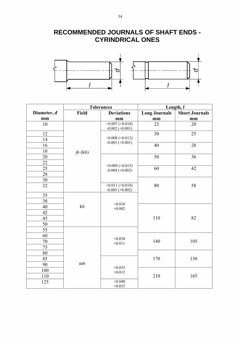
RECOMMENDED JOURNALS OF SHAFT ENDS - CYRINDRICAL ONES
Tolerances Length, l Diameter, d
mm Field Deviations
mm Long Journals
mm Short Journals
mm 10 +0.007 (+0.010)
-0.002 (+0.001) 23 20
12 14
30 25
16 18
+0.008 (+0.012) -0.003 (+0.001) 40 28
20 22
50 36
25 28
60 42
30
+0.009 (+0.015) -0.004 (+0.002)
32
j6 (k6)
+0.011 (+0.018) -0.005 (+0.002)
35 38
80
58
40 42 45 50
k6
+0.018 +0.002
55
110
82
60 70 75
140
105
80
+0.030 +0.011
85 90
170
130
100 110
+0.035 +0.013
125
m6
+0.040 +0.015
210
165
35
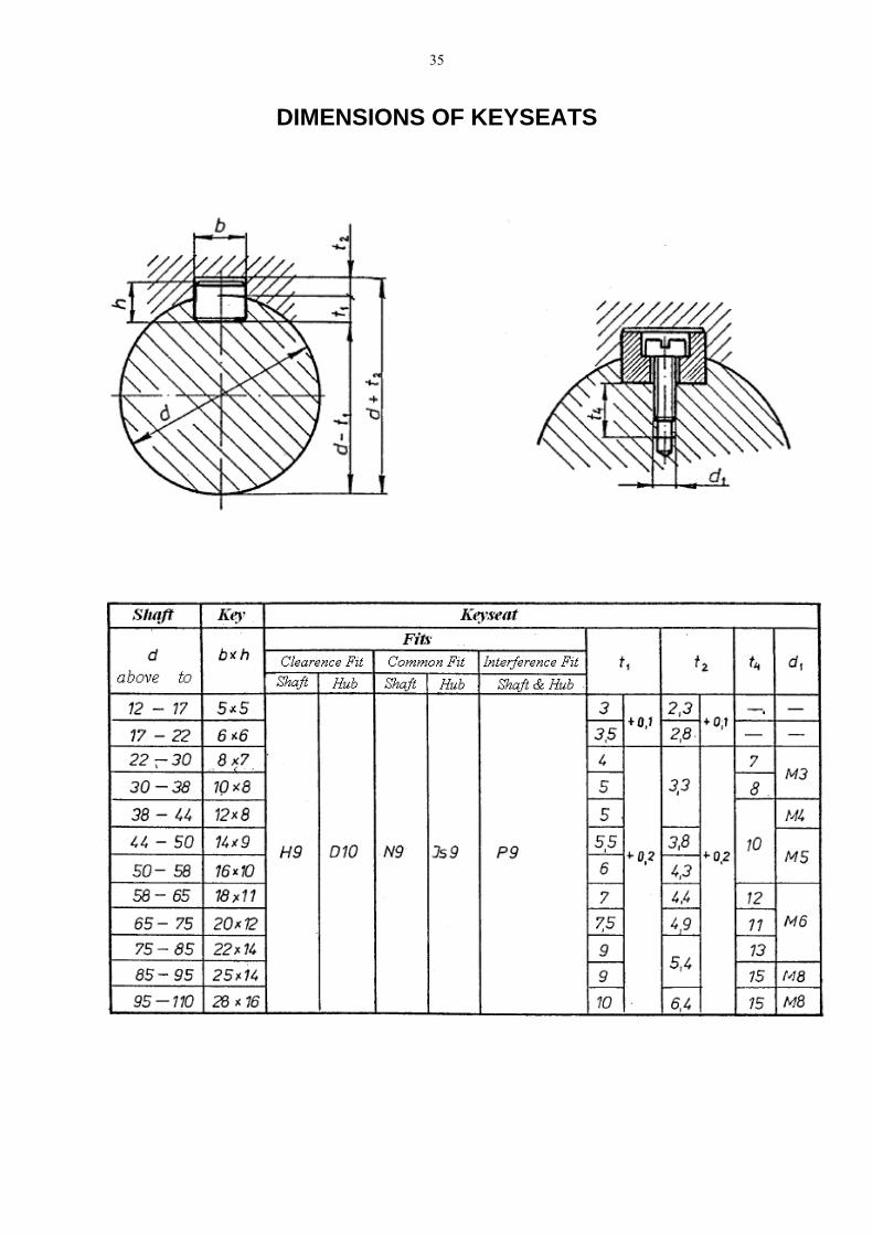
DIMENSIONS OF KEYSEATS
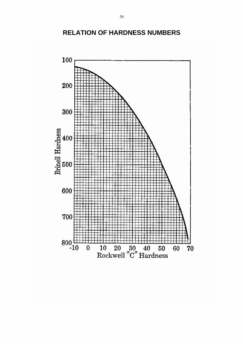
36
RELATION OF HARDNESS NUMBERS

37
RECOMMENDED NUMBER OF PINION TEETH ACCORDING TO NIEMANN
Gear ratio Proposed treatment
1:1 2:1 4:1 8:1 Heat treated up to 230 BHN 32…60 29…55 25…50 22…45 More than 300 BHN 30…50 27…45 23…40 20…35 Grey iron 26…45 23…40 21…35 18…30 Nitrided 24…40 21…35 19…31 16…26 Case hardened 21…32 19…29 16…25 14…22
SPUR GEAR DESIGN FORMULAS
To Obtain From Known Use This Formula*)
Pitch diameter Module D = m·N Circular pitch Module pc = m·π = (D·π)/m Module Diametral pitch m = 25.4/PdNo. of teeth Module and pitch
diameter N = D/m
Addendum Module a = m Dedendum Module b = 1.25·m Outside diameter Module and pitch
diameter or number of teeth
Do = D+2·m = m(N+2)
Root diameter Pitch diameter and module
Dr = D-2.5·m
Base circle diameter Pitch diameter and pressure angle
Db = D·cosφ
Base pitch Module and pressure angle
pb = m·π·cosφ
Tooth thickness at standard pitch diameter
Module T = 0.5·π·m
Center distance Module and number of teeth
C = 0.5·m(N1+N2)
Contact ratio Outside radii, base circle radii, center distance, pressure angle ϕπ
ϕcos
sin2211
⋅⋅−−+−
=m
CRRRRm bobo
p
Backlash (linear) Change in center distance
B = 2(∆C)tanφ
Backlash (linear) Change in tooth thickness
B = ∆T
Backlash (linear) along line-of-action
Linear backlash above pitch circle
BLA = B·cosφ
Backlash, angular Linear backlash B* =6.88(B/D) (arc minutes) Min. number teeth for no undercutting
Pressure angle Nc = 2/sin2φ
*) All linear dimensions in millimeters

38
LENGHT EXCESSES RECOMMENDED FOR THREADS
Excess Thread pitch, p L min L1 min L2 min L3 min a1
0.5 1 2 1 4 0.8 0.7 1 2.5 1.5 5 1.0 0.8 2 3 1.5 5.5 1.2 1.0 2 4 2 8 1.5
1.25 2 5 2.5 10.5 1.8 1.5 2 6 3 12 2.2
1.75 3 7 3.5 14.5 2.5 2.0 3 8 4 15 3.0 2.5 3 10 5 17 3.5 3.0 4 12 6 21 4.5 3.5 4 13 7 24 5.0 4.0 4 14 8 27 6.0

39
CASTING RIB DESIGN