beta low-voltage circuit protection - siemens€¦ · beta low-voltage circuit protection catalog...
TRANSCRIPT

Answers for industry.
BETA Low-Voltage Circuit ProtectionCharacteristic curves for fuses and information on configuration for catalog ET B1
Catalog Add-On ET B1 AO • 2009
� � � �
� � � �
� � � �
� � � �
� �
� � � �
� � �
� � � �
et_b1_ao_kennlinien_umschlag_2003 3et_b1_ao_kennlinien_umschlag_2003 3 22.10.2009 09:42:5222.10.2009 09:42:52
© Siemens AG 2009

Related Catalogs Contents
ALPHA Distribution Boards and Terminal BlocksOrder No.:pdf only: (E86060-K8210-A101-A9-7600)
ET A1 ALPHA SIMBOX Small Distribution Boards· SIMBOX 63, SIMBOX LC, SIMBOX WP · ALPHA 160 - DIN Wall-Mounted Distribution Boards· ALPHA 400 - DIN Wall-Mounted Distribution Boards· ALPHA 630 - DIN Floor-Mounted Distribution Boards· ALPHA AS Modular Distribution Boards· ALPHA Modular Distribution Boards up to1600 A · ALPHA 400-ZS Meter Cabinets· ALPHA BOX · ALPHA 8HP Molded-Plastic Distribution Systems· Planning and Configuration· ALPHA FIX terminal blocks: Screw Terminals, Terminals with Spring-Loaded Connection, Combination Plug-In Terminals, Plug-In Terminals, Insulation Displacement Terminals, Accessories for Terminal Blocks
ALPHA 400-ZS Meter CabinetsOrder No.:Regional catalogs available on request(available in German only)
ET A2 Region Z1 · Region Z2 · Region Z3 · Region Z4
BETA Low-Voltage Circuit ProtectionOrder No.:pdf only: (E86060-K8220-A101-B1-7600)
ET B1 Protecting: Miniature Circuit Breakers · Residual Current Pro-tective Devices · Low-VoltageFuse Systems · SITOR Semiconductor Fuses · SR60 Busbar Systems · Overvoltage Protection DevicesSwitching: Switches and Light Indicators · Switching Devices· Timers · Transformers, Bells and Socket OutletsMeasuring: Three-Phase Measuring Devices · Single-Phase Measuring DevicesMonitoring: Monitoring of Electrical Values · Monitoring of Plants and Devices
GAMMA Building Management SystemsOrder No.:pdf only: (E86060-K8230-A101-A9-7600)
ET G1 Display, Operation · Output Devices ·Input Devices · Combination Devices · Lighting · Sun Protection, Anti-glare Protection, Utilization of Daylight ·Heating, Cooling, Ventilation, Air-conditioning· Load Management · Safety · Quick-assembly Systems · Gateways, Interface Converters · Physical Sensors · Control and Automation Devices · System Products · System Accessories · Counters · Wave
DELTA Switches and Socket OutletsOrder No.:pdf only: (E86060-K8240-A101-A9-7600)
ET D1 i-system · DELTA line · DELTA vita · DELTA miro · DELTA profil · DELTA style · DELTA natur · DELTA ambiente · m-system · Surface-Mounting Product Range · Switching/Pushbutton Control/Dimming · Motion Detectors · Shutter/Blind Controls · Room Temperature Controllers · Data and Communication Systems · Remote Control Systems · Smoke Detectors · GAMMA Bus Coupling Unit
The Offline MallOrder No.:E86060-D4001-A510-C7-7600 (DVD)
CA 01 All products of automation, drives and installation technology,including those in the catalogs listed above.
The Online MallInternet:http://www.siemens.com/automation/mall
All products of automation, drives and installation technology,including those in the catalogs listed above.
Catalog-PDFInternet:http://www.automation.siemens.com/et
All catalogs for electrical installation technology can be down-loaded as PDF files.
Registered trademarks Technical AssistanceAll product designations may be registered trademarks or product names of Siemens AG or other supplying compa-nies. Third parties using these trademarks or product names for their own purposes may infringe upon the rights of the trademark owners.Further information about electrical installation is available on the Internet at:http://www.siemens.com/et
Expert technical assistance for Low-voltage controls and electrical installation.Tel: +49 (0) 180 5050 222 *Fax: +49 (0) 180 5050 223 *E-Mail: [email protected]
*0.14 €/min. from a German landline network, mobile telephone prices may vary
U2.fm Seite 1 Montag, 26. Oktober 2009 10:11 10
© Siemens AG 2009

BETA Low-Voltage Circuit Protection
Catalog Add-On ET B1 AO · 2009 Characteristic curves for fuses and information on configuration for catalog ET B1
Replaces:Catalog ET B1 AO · 2008, Characteristic curves for catalog ET B1
The products in this catalog can be also found in the electronic catalog CA 01.Order No.:E86060-D4001-A510-C7-7600 (DVD)
Contact your local Siemens representative
© Siemens AG 2009
The products and systems listed in this catalog are developed and manufactured using a VDE-approved quality management system according to EN ISO 9001:2000.
Protecting
Miniature Circuit Breakers 1
Residual Current Protective Devices2
Low-Voltage Fuse Systems3
SITOR Semiconductor Fuses4
SR60 Busbar Systems5
Overvoltage Protection Devices6
Switching
Switches and Light Indicators 7
Switching Devices8
Timers9
Transformers, Bells and Socket Outlets10
Measuring
Three-Phase Measuring Devices 11
Single-Phase Measuring Devices12
Monitoring
Monitoring of Electrical Values 13
Monitoring of Plants and Devices14
Appendix15
ET_B1_AO_Kennlinien.book Seite 1 Dienstag, 13. Oktober 2009 11:58 11
© Siemens AG 2009

Siemens ET B1 AO · 2009, Characteristic curves for fuses2
ET_B1_AO_Kennlinien.book Seite 2 Dienstag, 13. Oktober 2009 11:58 11
© Siemens AG 2009
3
Siemens ET B1 AO · 2009, Characteristic curves for fuses
3
BETA ProtectingLow-Voltage Fuse Systems
3/2 Introduction
3/5 NEOZED fuse systems
3/7 DIAZED fuse systems
3/13 Cylindrical fuse systems
3/19 Class CC fuse systems
3/21 LV HRC fuse links
ET_B1_AO_Kennlinien.book Seite 1 Dienstag, 13. Oktober 2009 11:58 11
© Siemens AG 2009
BETA ProtectingLow-Voltage Fuse Systems
Introduction
3/2 Siemens ET B1 AO · 2009, Characteristic curves for fuses
3 ■ Overview
Rated voltage Un
The rated voltage is the designated voltage of the fuse and and is used to determine its test conditions and operational voltage limits.
For LV HRC and SITOR fuse links, the rated voltage is always the r.m.s. value of an AC voltage.
In the case of NEOZED and DIAZED fuse links, a distinction is made between AC and DC voltage values.
Rated current InThe rated current of a fuse link is the designated current of the fuse link and is the current up to which it can be continuously loaded under prescribed conditions without adverse affects.
Rated frequency
The rated frequency is the frequency for which the fuse link is rated with regard to power dissipation, current, voltage, charac-teristic curve and breaking capacity.
Selectivity
Several fuses are usually connected in series in one system. And when things get serious, selectivity ensures that only the faulty electrical circuit of a system is switched off and not the entire operational process.
Siemens fuses of operational class gG, at an operational voltage of up to 400 V AC and a ratio of 1:1.25, are interselective, i.e. from rated current level to rated current level. This is achieved by means of the considerably smaller spread of ±5 % of the time/ current characteristic curve, which far exceeds the demand for a ratio of 1:1.6 specified in the standard.
It is therefore possible to use smaller conductor cross-sections due to the lower rated currents.
Breaking capacity
The rated breaking capacity is the highest prospective short-circuit current lp that the fuse link can blow under prescribed conditions.
A key feature of these fuses is their high rated breaking capacity with the smallest footprint. The basic demands and circuit data for tests – voltage, power factor, actuating angle, etc. – are specified in both national (DIN VDE 0636) and international (IEC 60269) regulations.
However, for a constant failsafe breaking capacity, from the smallest non-permissible overload current through to the highest breaking current, a number of quality characteristics need to be taken into account when designing and manufacturing fuse links. These include the design of the fuse element with regard to di-mensions and punch dimension and its position in the fuse body, as well as its compressive strength and the thermal resistance of the body. The chemical purity, particle size and the density of the quartz sand also play a key role.
The rated breaking capacity for AC voltage for NEOZED and the majority of DIAZED fuses - is 50 kA, and in the case of our LV HRC fuses, it is even 120 kA. The various type ranges of SITOR fuses have different switching capacities ranging from 50 to 100 kA.
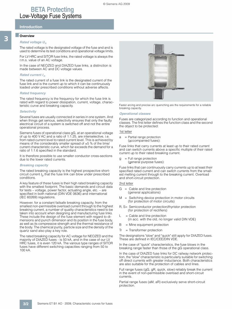
.
Faster arcing and precise arc quenching are the requirements for a reliable breaking capacity.
Operational classes
Fuses are categorized according to function and operational classes. The first letter defines the function class and the second the object to be protected:
1st letter
a = Partial range protection (accompanied fuses):
Fuse links that carry currents at least up to their rated current and can switch currents above a specific multiple of their rated current up to their rated breaking current.
g = Full range protection (general purpose fuses):
Fuse links that can continuously carry currents up to at least their specified rated current and can switch currents from the small-est melting current through to the breaking current. Overload and short-circuit protection.
2nd letter
G = Cable and line protection (general applications)
M = Switching device protection in motor circuits (for protection of motor circuits)
R, S= Semiconductor protection/thyristor protection (for protection of rectifiers)
L = Cable and line protection (in acc. with the old, no longer valid DIN VDE)
B = Mine equipment protection
Tr = Transformer protection
The designations "slow" and "quick" still apply for DIAZED fuses. These are defined in IEC/CEE/DIN VDE.
In the case of "quick" characteristics, the fuse blows in the breaking range faster than those of the gG operational class.
In the case of DIAZED fuse links for DC railway network protec-tion, the "slow" characteristic is particularly suitable for switching off direct currents with greater inductance. Both characteristics are also suitable for the protection of cables and lines.
Full range fuses (gG, gR, quick, slow) reliably break the current in the event of non-permissible overload and short-circuit currents.
Partial range fuses (aM, aR) exclusively serve short-circuit protection.
ET_B1_AO_Kennlinien.book Seite 2 Dienstag, 13. Oktober 2009 11:58 11
© Siemens AG 2009

BETA ProtectingLow-Voltage Fuse Systems
Introduction
3/3Siemens ET B1 AO · 2009, Characteristic curves for fuses
3The following operational classes are included in the product range:
gG (DIN VDE/IEC) = Full range cable and line protection
aM (DIN VDE/IEC) = Partial range switching device protection
aR (DIN VDE/IEC) = Partial range semiconductor protection
gR (DIN VDE/IEC) = Full range semiconductor protection
gS (DIN VDE/IEC) = Full range semiconductor protection and cable and line protection
Quick(DIN VDE/IEC/CEE) = Full range cable and line protection
Slow (DIN VDE) = Full range cable and line protection
Characteristic curves (Time/current characteristic curves)
The time/current characteristic curve specifies the virtual time (e.g. the melting time) as a function of the prospective current under specific operating conditions.
Melting times of fuse links are shown in the time/current dia-grams with logarithmic scale and depending on their currents. The melting time characteristic curve runs from the smallest melting current, which just about melts the fuse element, asymp-totic to the I2t lines of the same melting heat value in the range of the higher short-circuit currents, which specifies the constant melting heat value I2t. To avoid overcomplication, the time/ current characteristic curves diagrams omit the I2t lines (c).
General representation of the time/current characteristic curve of a fuse link of gL/gG operational class
Imin: Smallest melting current a: Melting time characteristic curve b: OFF time characteristic curve c: I2t line
The shape of the characteristic curve depends on the outward heat transfer from the fuse element. DIN VDE 0636 specifies tolerance-dependent time/current ranges within which the characteristic curves of the fuse must lie. Deviations of ± 10 % are permissible in the direction of the current axis. With Siemens LV HRC fuse links of gG operational class, the deviations work out at less than ± 5 %, a mark of our outstanding production accuracy. For currents up to approx. 20 In, the melting time-current characteristic curves are the same as the OFF time characteristic curves. In the case of higher short-circuit currents, the two characteristic curves move apart, influenced by the respective arc quenching time.
The difference between both lines (= arc quenching time) also depends on the power factor, the operational voltage and the breaking current.
The Siemens characteristic curves show the mean virtual melt-ing time characteristic curves recorded at an ambient tempera-ture of (20 ± 5) °C. They do not apply to preloaded fuse links.
Virtual time tvThe virtual time is the time span calculated when a I2t value is divided by the square of the prospective current:
The time/current characteristic curve specifies the prospective current Ip and the virtual melting time tvs.
Prospective short-circuit current Ip
The prospective short-circuit current is the r.m.s. value of the line-frequency AC component, or the value of the direct current to be expected in the event of a short-circuit occurring after the fuse, were the fuse to be replaced by a component of negligible impedance.
Let-through current characteristic curves
The let-through current characteristic curve specifies the value of the let-through current at 50 Hz as a function of the prospec-tive current.
The let-through current Ic is the maximum instantaneous value of the current reached during a switching operation of the fuse.
The fuse element of the fuse links melts so quickly at very high cur-rents that the surge short-circuit current Ip is prevented from oc-curring. The highest instantaneous value of the current reached during the shutdown cycle is called the let-through current Ic. The current limitations are specified in the current limiting diagrams, otherwise known as let-through current diagrams.
Oscillograph of a short-circuit current shutdown through a fuse link
I2_0
6996
a
10 10 10 10 � [A]
10
10
10[s]
a
b
c
� min
9
5
1
1 2 3 4
�
tv
i 2dt
Ip2
-----------------=
I2_0
6997
b
�
� P
c
s L
�
�
��
:
c
s
L
P
�
�
::::
Arc voltage
Maximum let-through currentPre-arcing timeArcing timePeak short-circuit current
ET_B1_AO_Kennlinien.book Seite 3 Dienstag, 13. Oktober 2009 11:58 11
© Siemens AG 2009

BETA ProtectingLow-Voltage Fuse Systems
Introduction
3/4 Siemens ET B1 AO · 2009, Characteristic curves for fuses
3Current limitation
As well as a failsafe rated breaking capacity, the current-limiting effect of a fuse link is of key importance for the cost effectiveness of a system. In the event of short-circuit breaking by a fuse, the breaking current continues to flow through the network until the fuse link is switched off. However, the breaking current is limited by the system impedance.
The simultaneous melting of all the bottlenecks of a fuse element produce a sequence of tiny partial arcs that ensure a fast break-ingoperation with strong current limitation. The current limitation is also strongly influenced by the production quality of the fuse – which in the case of Siemens fuses is extremely high. For exam-ple, an LV HRC fuse link, size 2 (224 A) limits a breaking current with a possible r.m.s. value of approximately 50 kA to a let-through current with a peak value of approx. 18 kA. This strong current limitation provides constant protection for the system against excessive loads.
Current limitation diagram; let-through current diagram of LV HRC fuse links, size 00, operational class gL/gG, rated currents 6 A, 10 A, 50 A, 100 A
Legend
tvs = Virtual melting time
Ic = Max. let-through current
Ieff = R.m.s. value of the prospective short-circuit current
I2ts = Melting I2t value
I2ta = Breaking I2tvalue
In = Rated current
Pv = Rated power dissipation
DJ = Temperature rise
kA = Correction factor for I2t value
Uw = Recovery voltage
Ûs = Peak arc voltage
ip = Peak short-circuit current$ = Peak short-circuit current with largest DC component% = Peak short-circuit current without DC component
U = Voltage
i = Current
ts = Melting time
tL = Arc quenching time
Rated power dissipation
Rated power dissipation is the power loss during the load of a fuse link with its rated current under prescribed conditions.
The cost effectiveness of a fuse depends largely on the rated power dissipation (power loss). This should be as low as possi-ble and have low self-heating. However, when assessing the power loss of a fuse, it must also be taken into account that there is a physical dependence between the rated breaking capacity and the rated power dissipation. On the one hand, fuse elements need to be thick in order to achieve the lowest possible resis-tance value, on the other, a high rated breaking capacity requires the thinnest possible fuse elements in order to achieve reliable arc quenching.
Siemens fuses have the lowest possible rated power dissipation while also providing the highest possible load breaking reliabil-ity.
These values lie far below the limit values specified in the regula-tions. This means low temperature rises, reliable breaking capacity and high cost effectiveness.
I2t value
The I2t value (joule integral) is the integral of the current squared over a specific time interval:
Specifies the I2t values for the melting process (I2ts) and for the shutdown cycle (I2tA, sum of melting and quenching I2t value). The melting I2t value, also known as the total I2t value or break-ing I2t value, is particularly important when dimensioning SITOR fuses for semiconductor protection. This value depends on the voltage and is specified with the rated voltage.
Peak arc voltage Ûs
The peak arc voltage is the highest value of the voltage that occurs at the contacts of the fuse link during the arc quenching time.
Residual value factor RW
The residual value factor is a reduction factor for determining the permissible load period of the fuse link with currents that exceed the permissible load current In' (see rated current In). This factor is applied when dimensioning SITOR fuses for semiconductor pro-tection.
Varying load factor WL
The varying load factor is a reduction factor for the rated current with varying load states. This factor is applied when dimension-ing SITOR fuses for semiconductor protection.
Recovery voltage Uw
The recovery voltage (r.m.s. value) is the voltage that occurs at the contacts of a fuse link after the power is cut off.
I2_0
6998
a
�
100 A�
50 A
10 A
6 A
c
eff
I2t i 2 tdt0
t1=
ET_B1_AO_Kennlinien.book Seite 4 Dienstag, 13. Oktober 2009 11:58 11
© Siemens AG 2009
BETA ProtectingLow-Voltage Fuse Systems
NEOZED fuse systems
3/5Siemens ET B1 AO · 2009, Characteristic curves for fuses
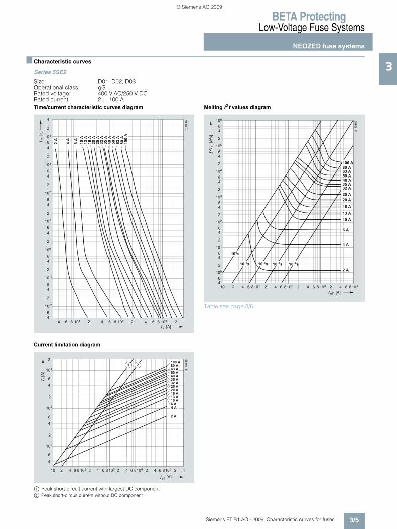
3■ Characteristic curves
Series 5SE2
Size: D01, D02, D03Operational class: gGRated voltage: 400 V AC/250 V DCRated current: 2 ... 100 ATime/current characteristic curves diagram
Current limitation diagram
$ Peak short-circuit current with largest DC component% Peak short-circuit current without DC component
Melting I2t values diagram
Table see page 3/6.
� � � �
��� ��
���
� � � � � � � � � � � � � � � � �
�
�
�� �
�
�
�
�
�
�
� �
�
�
�
�
� �
�
�
�
�
�
�
� �
�
�
�
� �
� �
�
�
���
���
���
����
���
����
����
���
���
��
���
����
���
����
�����
��
� � �� � �� � �� � � ��
�
�
�
�
�
�
�
�
� � �� � �
���
������
�
�
�
�
�
� �
�
�
�
� � � � � � � � � � �
�
� � �
� � �
� � � � �
� � � �
� � �
� � �
� � � �
� �
� � �
� � �
� � � �
� � � �
� � �
� � � �
� � �
� � � � �� � �� � � � �� � �� �� � � �� ��
�
�
�
�
�
�
�
�
�
�
�
�
�
�
�
�
�
�
�
�
�
�
�
�
�
������
�
�
�
�
�
�
� � � � � �
��
�����
�
�
�
� ���
� � �� � �
�� � �
� � �
��
� � � �
� � �
� � �
� � � �
� �
� � �
� � � �
� � � �
� � �
� � � �
� � �
� � �
� � �
� � �
� � � � �
ET_B1_AO_Kennlinien.book Seite 5 Dienstag, 13. Oktober 2009 11:58 11
© Siemens AG 2009

BETA ProtectingLow-Voltage Fuse Systems
NEOZED fuse systems
3/6 Siemens ET B1 AO · 2009, Characteristic curves for fuses
3Series 5SE2
Size: D01, D02, D03Operational class: gGRated voltage: 400 V AC /250 V DCRated current: 2 ... 100 A
Type In Pv DJ I2ts I2ta1 ms 4 ms 230 V AC 400 V AC
(t < 4 ms)
A W K A2s A2s A2s A2s
5SE2 302 2 1.6 19 1.2 1.4 2.9 3.95SE2 304 4 1.3 14 12.5 13.6 22 305SE2 306 6 1.7 19 46.7 48 58 75
5SE2 310 10 1.3 16 120 136 220 2805SE2 013-2A 13 1.95 23 220 244 290 3705SE2 316 16 2.1 24 375 410 675 890
5SE2 320 20 2.4 26 740 810 1250 16505SE2 325 25 3.2 33 1210 1300 1900 26005SE2 332 32 3.6 34 2560 2800 4300 5500
5SE2 335 35 3.8 36 3060 3500 5100 65005SE2 340 40 4 37 4320 4800 7900 95005SE2 350 50 4.2 38 6750 7400 10500 13000
5SE2 363 63 5.3 45 10000 10900 16000 205005SE2 280 80 5.3 43 13000 15400 25000 345005SE2 300 100 6.4 47 22100 30000 46000 60000
ET_B1_AO_Kennlinien.book Seite 6 Dienstag, 13. Oktober 2009 11:58 11
© Siemens AG 2009
BETA ProtectingLow-Voltage Fuse Systems
DIAZED fuse systems
3/7Siemens ET B1 AO · 2009, Characteristic curves for fuses
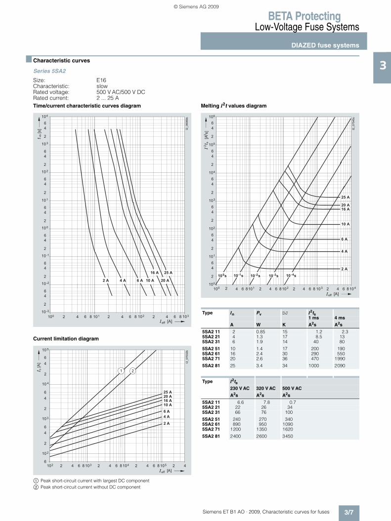
3■ Characteristic curves
Series 5SA2
Size: E16Characteristic: slowRated voltage: 500 V AC/500 V DCRated current: 2 ... 25 ATime/current characteristic curves diagram
Current limitation diagram
$ Peak short-circuit current with largest DC component% Peak short-circuit current without DC component
Melting I2t values diagram
� � �
� � �
�
�
�
� � �
�� � � � �� � �� � �
�
�
�
� �
�
�
�
� �
�
�
�
�
�
�
�
� �
�
�
�
� �
�
�
�
� �
��������
� � ��
� � �
��
� � � � � �
���
� � � � � � � � � � � � � �
� � � � � � �
� � � �� � ��
�
�
�
�
�
�
�
��� ����
�
� � �
�
� � �� � �
���
� �
�
� �
�
�
�
� �
� �� � �� � �� � �� � �
� � �
� � �
� � � �
� � � �
� � � �
� � �
�
Type In Pv DJ I2ts1 ms 4 ms
A W K A2s A2s
5SA2 11 2 0.85 15 1.2 2.35SA2 21 4 1.3 17 8.5 135SA2 31 6 1.9 14 40 80
5SA2 51 10 1.4 17 200 1905SA2 61 16 2.4 30 290 5505SA2 71 20 2.6 36 470 1990
5SA2 81 25 3.4 34 1000 2090
Type I2ta230 V AC 320 V AC 500 V AC
A2s A2s A2s
5SA2 11 6.6 7.8 0.75SA2 21 22 26 345SA2 31 66 76 100
5SA2 51 240 270 3405SA2 61 890 950 10905SA2 71 1200 1350 1620
5SA2 81 2400 2600 3450
� � � � �� � �� � � � �� � �� �� � � �� ��
�
�
�
�
�
�
�
�
�
�
�
�
�
�
�
�
�
�
�
�
�
�
�
�
�
��� ����
�
�
�
�
�
�
� � �
� � � �
� � � �
� � �
� � � � � �
��
�����
�
� � � � � � � � � � � � � � � � � � �
� � �
� � �
� � � �
ET_B1_AO_Kennlinien.book Seite 7 Dienstag, 13. Oktober 2009 11:58 11
© Siemens AG 2009
BETA ProtectingLow-Voltage Fuse Systems
DIAZED fuse systems
3/8 Siemens ET B1 AO · 2009, Characteristic curves for fuses
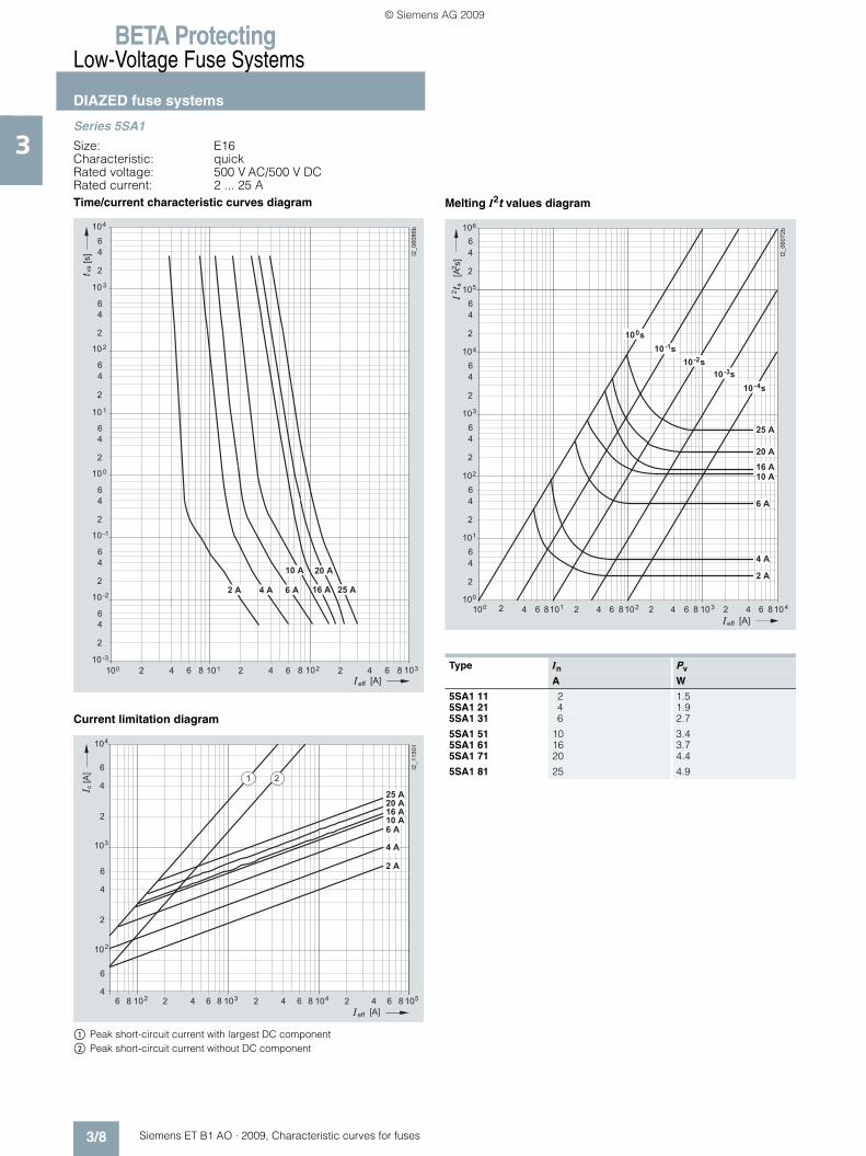
3Series 5SA1
Size: E16Characteristic: quickRated voltage: 500 V AC/500 V DCRated current: 2 ... 25 ATime/current characteristic curves diagram
Current limitation diagram
$ Peak short-circuit current with largest DC component% Peak short-circuit current without DC component
Melting I2t values diagram
� � �
� � �
�
�
�
� � �
�� � � � �� � �� � �
�
�
�
� �
�
�
�
� �
�
�
�
�
�
�
�
� �
�
�
�
� �
�
�
�
� �
��������
� � ��
��
� � � � � �
���
� � � � � � � � � � � � �
� � � �
� � �
� � � �
��
� �� ��
� � � � � �
�� �� ��
�� �� ��
�
����
� � �
� � � �
� � �
�
�
�
�
�
�
�
�
�
����
�
�
��
�
��
�
� � �
� � � �
� � � �
� � �
Type In Pv
A W
5SA1 11 2 1.55SA1 21 4 1.95SA1 31 6 2.7
5SA1 51 10 3.45SA1 61 16 3.75SA1 71 20 4.4
5SA1 81 25 4.9
� � � � �� � �� � � � �� � �� �� � � �� ��
�
�
�
�
�
�
�
�
�
�
�
�
�
�
�
�
�
�
�
�
�
�
�
�
�
����� ��
�
�
�
�
�
�
� � �
� � � � � �
��
�����
�
� � � �
� � �
� � �
� � � �
� � � �
� � �
� � � �
� � � �
� � � �
� � �
� � � �
ET_B1_AO_Kennlinien.book Seite 8 Dienstag, 13. Oktober 2009 11:58 11
© Siemens AG 2009

BETA ProtectingLow-Voltage Fuse Systems
DIAZED fuse systems
3/9Siemens ET B1 AO · 2009, Characteristic curves for fuses
3Series 5SB2, 5SB4, 5SC2
Size: DII, DIII, DIVOperational class: gGRated voltage: 500 V AC/500 V DCRated current: 2 ... 100 ATime/current characteristic curves diagram
Current limitation diagram
$ Peak short-circuit current with largest DC component% Peak short-circuit current without DC component
Melting I2t values diagram
� � �
� � �
�
�
�
� � �
�� � � � �� � �� � �
�
�
�
� �
�
�
�
� �
�
�
�
�
�
�
�
� �
�
�
�
� �
�
�
�
� �
� � ��
��
� � � � � �
���
�
��� ���
���
���
���
����
����
����
���
���
��
���
���
����
�����
� � � �� � ��
�
�
�
�
�
�
�
��������
�
� � �
�
� � �� � �
���
� �
�
� �
�
�
�
� �
� �� � �� � �� � �� � �
� � �
� � �
� � � �
� � � �
� � � �
� � �
� � �
� � �
� � �
� � � �
� � � � �
�
� �
Type In Pv DJ I2ts1 ms 4 ms
A W K A2s A2s
5SB2 11 2 2.6 15 3.7 3.9 5SB2 21 4 2.0 13 15 16 5SB2 31 6 2.2 14 42 45
5SB2 51 10 1.6 20 120 140 5SB2 61 16 2.4 23 500 580 5SB2 71 20 2.6 26 750 1100
5SB2 81 25 3.4 38 1600 2000 5SB4 010 32 3.6 23 2300 2500 5SB4 11 35 3.7 25 3450 3000 5SB4 21 50 5.7 41 6500 5200
5SB4 31 63 6.9 48 11000 12000 5SC2 11 80 7.5 33 14600 16400 5SC2 21 100 8.8 46 28600 30000
Type I2ta230 V AC 320 V AC 500 V AC
A2s A2s A2s
5SB2 11 6.6 8.8 10.7 5SB2 21 22 28 34 5SB2 31 66 85 100
5SB2 51 240 300 340 5SB2 61 890 1060 1090 5SB2 71 1200 1450 1620
5SB2 81 2400 3150 3450 5SB4 010 3450 4150 4850 5SB4 11 5200 6200 7200 5SB4 21 9750 12350 14500
5SB4 31 16500 22200 26500 5SC2 11 23000 28500 32500 5SC2 21 44000 56000 65000
� � � � �� � �� � � � �� � �� �� � � �� ��
�
�
�
�
�
�
�
�
�
�
�
�
�
�
�
�
�
�
�
�
�
�
�
�
�
��� ����
�
�
�
�
�
�
� � �
� � � �
� � � �
� � �
� � � � � �
��
�����
�
� � �
� � �
� � � �
� � � � �
� � � �
� � �
� � �
� �
� ���
� � �� � �
�� � �
� � �
��
� � �
ET_B1_AO_Kennlinien.book Seite 9 Dienstag, 13. Oktober 2009 11:58 11
© Siemens AG 2009
BETA ProtectingLow-Voltage Fuse Systems
DIAZED fuse systems
3/10 Siemens ET B1 AO · 2009, Characteristic curves for fuses
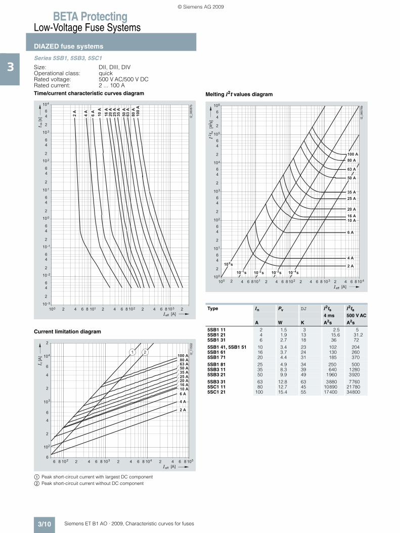
3Series 5SB1, 5SB3, 5SC1
Size: DII, DIII, DIVOperational class: quickRated voltage: 500 V AC/500 V DCRated current: 2 ... 100 ATime/current characteristic curves diagram
Current limitation diagram
$ Peak short-circuit current with largest DC component% Peak short-circuit current without DC component
Melting I2t values diagram
� � �
� � �
�
�
�
� � �
�� � � � �� � �� � �
�
�
�
� �
�
�
�
� �
�
�
�
�
�
�
�
� �
�
�
�
� �
�
�
�
� �
� � ��
��
� � � � � �
���
�
������ �
���
���
���
����
����
����
���
��
���
���
����
�����
��
� �� ��
� � � � � �
�� �� ��
�� �� ��
�
�����
� � � �
� � �
�
�
�
�
�
�
�
�
����
�
�
� �
�
��
� � � �
� � � �
� � �
�
�
� � �
� � �
� � � � �
� � � �
� � �
� �
� � �
Type In Pv DJ I2ts I2ta4 ms 500 V AC
A W K A2s A2s
5SB1 11 2 1.5 3 2.5 55SB1 21 4 1.9 13 15.6 31.25SB1 31 6 2.7 18 36 72
5SB1 41, 5SB1 51 10 3.4 23 102 2045SB1 61 16 3.7 24 130 2605SB1 71 20 4.4 31 185 370
5SB1 81 25 4.9 34 250 5005SB3 11 35 8.3 39 640 12805SB3 21 50 9.9 49 1960 3920
5SB3 31 63 12.8 63 3880 77605SC1 11 80 12.7 45 10890 217805SC1 21 100 15.4 55 17400 34800
� � � � �� � �� � � � �� � �� �� � � �� ��
�
�
�
�
�
�
�
�
�
�
�
�
�
�
�
�
�
�
�
�
�
�
�
�
�
����� ��
�
�
�
�
�
�
� � � � � �
��
�����
�� � � �
� � � �
� � �
� � �
� � �
� � � �
� � � �
� � �
� �
� � �
� � � � �
� � �
� ���
� � �� � �
�� � �
� � �
��
ET_B1_AO_Kennlinien.book Seite 10 Dienstag, 13. Oktober 2009 11:58 11
© Siemens AG 2009

BETA ProtectingLow-Voltage Fuse Systems
DIAZED fuse systems
3/11Siemens ET B1 AO · 2009, Characteristic curves for fuses
3Series 5SD8
Size: DIIIOperational class: gGRated voltage: 690 V AC/600 V DCRated current: 2 ... 63 ATime/current characteristic curves diagram
Current limitation diagram
$ Peak short-circuit current with largest DC component% Peak short-circuit current without DC component
Melting I2t values diagram
� � �
� � �
�
�
�
� � �
�� � � � �� � �� � �
�
�
�
� �
�
�
�
� �
�
�
�
�
�
�
�
� �
�
�
�
� �
�
�
�
� �
�������
� � ��
��
� � �� � �
���
� � � � � � � � � � � � � � � � �
� � � � � � � � � � � � � � � �
� � � �� � ��
�
�
�
��� ��
� � �
�
� � �� � �
���
�
� �� � �� � �� � �� � �
� � �
� � �
� � � �
� � � �
� � � �
� � �
�
� �
�
�
�
� �
�
�
� � �
� � �
� �
�
Type In Pv I2ts I2ta4 ms 242 V AC
A W A2s A2s
5SD8 002 2 1 4.4 75SD8 004 4 1.2 40 625SD8 006 6 1.6 88 140
5SD8 010 10 1.4 240 3805SD8 016 16 1.8 380 6005SD8 020 20 2 750 1200
5SD8 025 25 2.3 2000 32005SD8 035 35 3.1 3300 51005SD8 050 50 4.6 7000 11000
5SD8 063 63 5.5 9500 15000
� � � � �� � �� � � � �� � �� �� � � �� ��
�
�
�
�
�
�
�
�
�
�
�
�
�
�
�
�
�
�
�
�
�
�
�
�
�
��������
�
�
�
�
�
�
� � �
� � � � � �
��
�����
�
� � � � � � � � � � � � � � � � � � �
� � �
� � � �
� � � �
� � �
� � �
� � � �
� �
� � �
� � �
ET_B1_AO_Kennlinien.book Seite 11 Dienstag, 13. Oktober 2009 11:58 11
© Siemens AG 2009
BETA ProtectingLow-Voltage Fuse Systems
DIAZED fuse systems
3/12 Siemens ET B1 AO · 2009, Characteristic curves for fuses
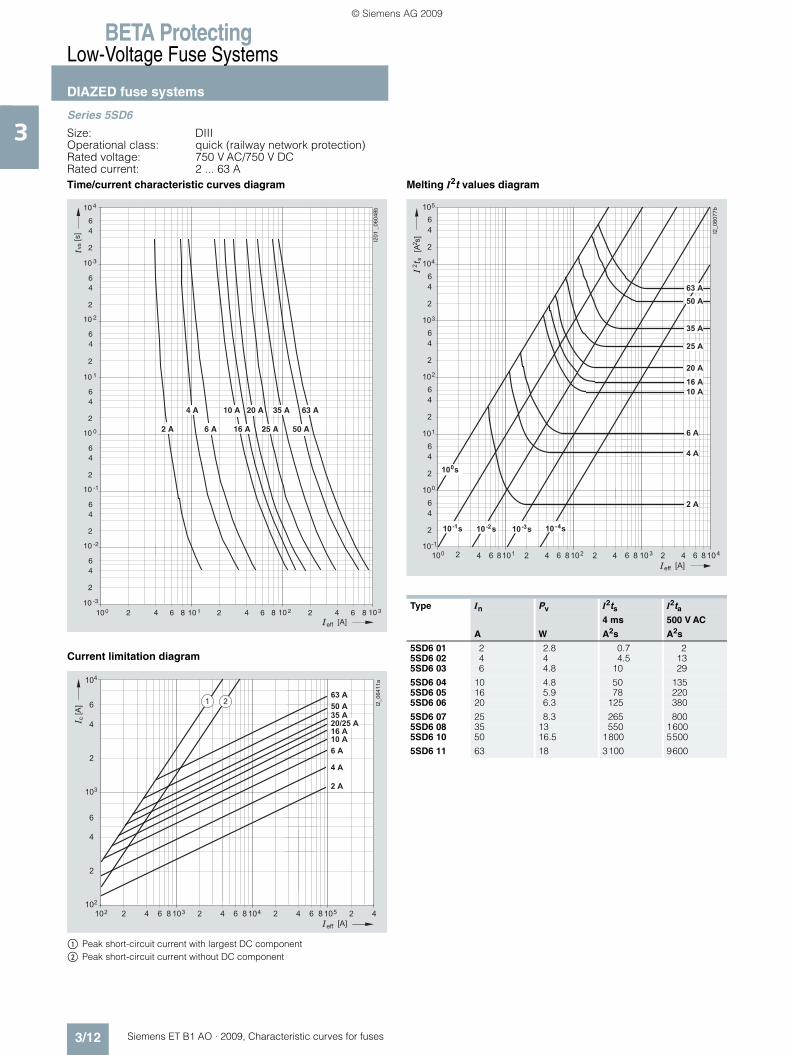
3Series 5SD6
Size: DIIIOperational class: quick (railway network protection)Rated voltage: 750 V AC/750 V DCRated current: 2 ... 63 ATime/current characteristic curves diagram
Current limitation diagram
$ Peak short-circuit current with largest DC component% Peak short-circuit current without DC component
Melting I2t values diagram
210010 -3
2
46
10 -2
64 10 18 2 64 10 28 2 4
2
46
10 -1
2
46
10 0
2
46
10 1
2
46
10 2
2
46
10 3
2
46
10 4
6 10 38
vs
[A]
[s]
2 A 6 A 50 A25 A16 A
4 A 10 A 20 A 35 A 63 A
I201
_06
048b
eff
� � � �� � ��
�
�
������
� � �
�
� � �� � �
���
�
� �� � �� � �� � �� � �
� � �
� � �
� � � �
� � � �
� � � � � �
�
� �
�
�
�
��
�
� � �
� � �
� �
�
Type In Pv I2ts I2ta4 ms 500 V AC
A W A2s A2s
5SD6 01 2 2.8 0.7 25SD6 02 4 4 4.5 135SD6 03 6 4.8 10 29
5SD6 04 10 4.8 50 1355SD6 05 16 5.9 78 2205SD6 06 20 6.3 125 380
5SD6 07 25 8.3 265 8005SD6 08 35 13 550 16005SD6 10 50 16.5 1800 5500
5SD6 11 63 18 3100 9600
� � � � �� � �� � � � �� � �� �� � � �� ��
�
�
�
�
�
�
�
�
�
�
�
�
�
�
�
�
�
�
�
�
�
�
�
�
�
����� �
�
�
�
�
�
�
� � � � � �
��
�����
�
� � �
� � �
� � �
� � � �
� � � �
� � � �
� � �
� �
� � �
� � �
� � �� � �
�� � �
� � �
��
� ���
ET_B1_AO_Kennlinien.book Seite 12 Dienstag, 13. Oktober 2009 11:58 11
© Siemens AG 2009
BETA ProtectingLow-Voltage Fuse Systems
Cylindrical fuse systems
3/13Siemens ET B1 AO · 2009, Characteristic curves for fuses
3■ Characteristic curves
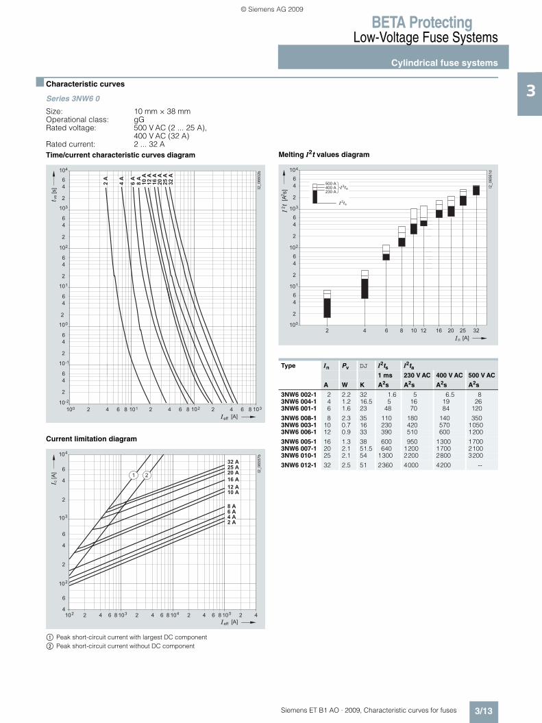
Series 3NW6 0
Size: 10 mm × 38 mmOperational class: gGRated voltage: 500 V AC (2 ... 25 A),
400 V AC (32 A)Rated current: 2 ... 32 ATime/current characteristic curves diagram
Current limitation diagram
$ Peak short-circuit current with largest DC component% Peak short-circuit current without DC component
Melting I2t values diagram
� � �
� � �
�
�
�
� �
�� � � � �� � �� � �
�
�
�
� �
�
�
�
�
�
�
�
� �
�
�
�
� �
�
�
�
� �
��������
� � ��
��
� � �� � �
���
���
���
���
���
����
����
����
����
���
���
��
� �� ��
�
�
�
�
�
�
�
�
� � � � � �
���
��
�
�� �� ��
�� �� ��
�� �
������ �
�
��
�
� � �
� � �
� � �
� � � �
� � � �
� � �
�
� � � �
� � � �
� � �
� � �
Type In Pv DJ I2ts I2ta1 ms 230 V AC 400 V AC 500 V AC
A W K A2s A2s A2s A2s
3NW6 002-1 2 2.2 32 1.6 5 6.5 83NW6 004-1 4 1.2 16.5 5 16 19 263NW6 001-1 6 1.6 23 48 70 84 120
3NW6 008-1 8 2.3 35 110 180 140 3503NW6 003-1 10 0.7 16 230 420 570 10503NW6 006-1 12 0.9 33 390 510 600 1200
3NW6 005-1 16 1.3 38 600 950 1300 17003NW6 007-1 20 2.1 51.5 640 1200 1700 21003NW6 010-1 25 2.1 54 1300 2200 2800 3200
3NW6 012-1 32 2.5 51 2360 4000 4200 --
�
�
�
�
�
�
�
�
�
�
�
�
�
�
�
�
�
�
�������
�
�
�
�
� � � �
������
�
� � � � �
�
� � � � �
� � � � �
� � � � �
��
��
�
� � � � � � �
ET_B1_AO_Kennlinien.book Seite 13 Dienstag, 13. Oktober 2009 11:58 11
© Siemens AG 2009
BETA ProtectingLow-Voltage Fuse Systems
Cylindrical fuse systems
3/14 Siemens ET B1 AO · 2009, Characteristic curves for fuses
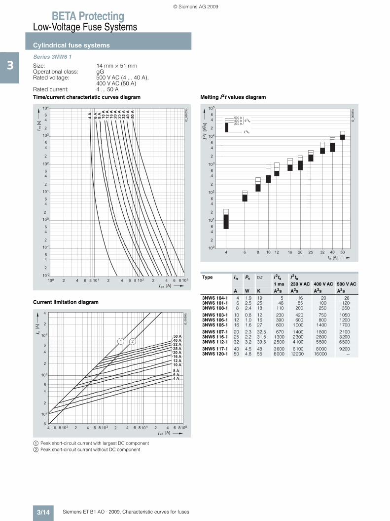
3Series 3NW6 1
Size: 14 mm × 51 mmOperational class: gGRated voltage: 500 V AC (4 ... 40 A),
400 V AC (50 A)Rated current: 4 ... 50 ATime/current characteristic curves diagram
Current limitation diagram
$ Peak short-circuit current with largest DC component% Peak short-circuit current without DC component
Melting I2t values diagram
� � �
� � �
�
�
�
� �
�� � � � �� � �� � �
�
�
�
� �
�
�
�
�
�
�
�
� �
�
�
�
� �
�
�
�
� �
��������
� � ��
��
� � �� � �
���
���
���
����
����
����
���
���
����
���
���
����
102
c
eff [A]
[A]
10
I2_
06
56
0c
2
4 6 8 2 1034 6 8 2 1044 6 8 2 1054 6 8
2
4
6
6
103
2
4
2
4
6
104
1 2
4 A
6 A
8 A
10 A
12 A
16 A
20 A
25 A
32 A
40 A
50 A
Type In Pv DJ I2ts I2ta1 ms 230 V AC 400 V AC 500 V AC
A W K A2s A2s A2s A2s
3NW6 104-1 4 1.9 19 5 16 20 263NW6 101-1 6 2.5 25 48 85 100 1203NW6 108-1 8 2.4 18 110 200 250 350
3NW6 103-1 10 0.8 12 230 420 750 10503NW6 106-1 12 1.0 16 390 600 800 12003NW6 105-1 16 1.6 27 600 1000 1400 1700
3NW6 107-1 20 2.3 32,5 670 1400 1800 21003NW6 116-1 25 2.2 31.5 1300 2300 2800 32003NW6 112-1 32 3.2 39.5 2500 4100 5500 6500
3NW6 117-1 40 4.5 48 3600 6100 8000 92003NW6 120-1 50 4.8 55 8000 12200 16000 --
�
�
�
�
�
�
�
�
�
�
�
�
�
�
�
�
�
��������
�
�
�
�
� � � �
������
�
�
� � � � �
� � � � �
� � � � �
��
��
�
�
�
�
��
� � � � � � � �� � � � � �� �
ET_B1_AO_Kennlinien.book Seite 14 Dienstag, 13. Oktober 2009 11:58 11
© Siemens AG 2009
BETA ProtectingLow-Voltage Fuse Systems
Cylindrical fuse systems
3/15Siemens ET B1 AO · 2009, Characteristic curves for fuses
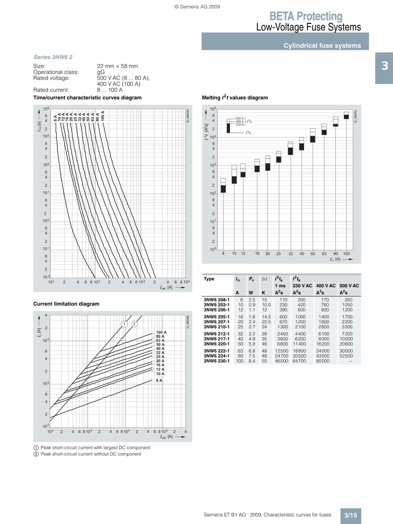
3Series 3NW6 2
Size: 22 mm × 58 mmOperational class: gGRated voltage: 500 V AC (8 ... 80 A),
400 V AC (100 A)Rated current: 8 ... 100 ATime/current characteristic curves diagram
Current limitation diagram
$ Peak short-circuit current with largest DC component% Peak short-circuit current without DC component
Melting I2t values diagram
� �
� � �
�
�
�
� �
�� � �� � �� � �� � �
�
�
�
� �
�
�
�
�
�
�
�
� �
�
�
�
� �
�
�
�
� �
��������
� � ��
��
� � �� � �
��� ����
����
���
���
����
���
���
����
�����
����
����
���
��
� �� ��
�
�
�
�
�
� � �� � �
���
�
�
�� �� ��
�� �� ��
�� �
��������
�
�
�
� � � �
� � � �
� � �
� � �
�
�
�
�
�
� � � �
� � �
� � �
� � � �
� � � � �
�
� � � �
� � � �
� � �
Type In Pv DJ I2ts I2ta1 ms 230 V AC 400 V AC 500 V AC
A W K A2s A2s A2s A2s
3NW6 208-1 8 2.5 15 110 200 170 3503NW6 203-1 10 0.9 10.5 230 420 760 10503NW6 206-1 12 1.1 12 390 600 800 1200
3NW6 205-1 16 1.6 14.5 600 1000 1400 17003NW6 207-1 20 2.4 22.5 670 1200 1800 22003NW6 210-1 25 2.7 24 1300 2100 2800 3300
3NW6 212-1 32 3.2 28 2450 4400 6100 72003NW6 217-1 40 4.9 35 3600 6200 8000 100003NW6 220-1 50 5.9 46 6800 11400 16200 20600
3NW6 222-1 63 6.8 48 12500 18800 24000 300003NW6 224-1 80 7.5 48 24700 30500 43000 525003NW6 230-1 100 8.4 55 46000 64700 80000 --
�
�
�
�
�
�
�
�
�
�
�
�
�
�
�
�
�
��������
�
�
�
�
� � � �
������
�
�
� � � � �
� � � � �
� � � � �
��
��
�
�
�
�
��
� � �� � � �� � � � � �� � � � � ��
ET_B1_AO_Kennlinien.book Seite 15 Dienstag, 13. Oktober 2009 11:58 11
© Siemens AG 2009
BETA ProtectingLow-Voltage Fuse Systems
Cylindrical fuse systems
3/16 Siemens ET B1 AO · 2009, Characteristic curves for fuses
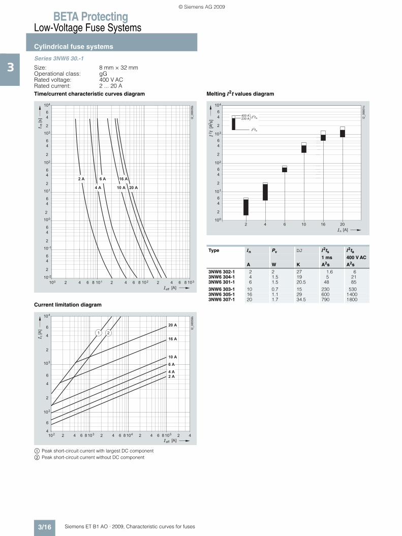
3Series 3NW6 30.-1
Size: 8 mm × 32 mmOperational class: gGRated voltage: 400 V ACRated current: 2 ... 20 ATime/current characteristic curves diagram
Current limitation diagram
$ Peak short-circuit current with largest DC component% Peak short-circuit current without DC component
Melting I2t values diagram
� � �
� � �
�
�
�
� �
�� � � � �� � �� � �
�
�
�
� �
�
�
�
�
�
�
�
� �
�
�
�
� �
�
�
�
� �
��������
� � ��
��
� � �� � �
���
� � � � � � � � � � �
� � � � � � � � � �
��
� �� ��
�
�
�
�
�
�
�
�
� � � � � �
���
��
�
�� �� ��
�� �� ��
�� �
��������
�
��
�
�
� � �
� � �
� � � �
� � � �
� � � �
� � �
Type In Pv DJ I2ts I2ta1 ms 400 V AC
A W K A2s A2s
3NW6 302-1 2 2 27 1.6 63NW6 304-1 4 1.5 19 5 213NW6 301-1 6 1.5 20.5 48 85
3NW6 303-1 10 0.7 15 230 5303NW6 305-1 16 1.1 29 600 14003NW6 307-1 20 1.7 34.5 790 1800
�
�
�
�
�
�
�
�
�
�
�
�
�
�
�
�
�
�
�������
�
�
�
�
� � � �
������
�
� � � � � �
�� � � � �
� � � � ��
�
��
�
ET_B1_AO_Kennlinien.book Seite 16 Dienstag, 13. Oktober 2009 11:58 11
© Siemens AG 2009

BETA ProtectingLow-Voltage Fuse Systems
Cylindrical fuse systems
3/17Siemens ET B1 AO · 2009, Characteristic curves for fuses
3Series 3NW8
Size: 10 mm × 38 mm 14 mm × 51 mm 22 mm × 58 mm
Operational class: aMRated voltage: 500 V AC,
400 V AC (3NW8 120-1, 3NW8 230-1)Rated current: 0,5 ... 100 ATime/current characteristic curves diagram
Current limitation diagram
$ Peak short-circuit current with largest DC component% Peak short-circuit current without DC component
Melting I2t values diagram
�
� � �
�
�
�
� � �
�� � � �� � �� � �
�
�
�
� �
�
�
�
� �
�
�
�
�
�
�
�
� �
�
�
�
� �
������ �
� � ��
��
� � �� � �
���
����
����
���
���
����
���
���
����
�����
� � �
����
���
���
���
����
����
���
���
��
�
�
� � �� � �
���
�
��������
�
� � � � ��
� � � � ��
� � � � ��
� � � �
�
�
�
��
�
�
�
��
�
�
� � � �
� � � � �
� � � �
� � �
� � �
� � � �
� � �
� � �
� � � �
� � � �
� � � �
� � � �
� � �
� � �
� � �
� � �
� � �
�
�
�
�
�
�
�
�
�
�
�
�
�
�
�
�
�
�
�
�
�
� � � �
������
�
� �
�
�
�
��
�
��������
�
�
�
��
�� � � � �
� � � � ��
�
��
�
� � � � � � � � � � � � � � � � � � � �� � �
ET_B1_AO_Kennlinien.book Seite 17 Dienstag, 13. Oktober 2009 11:58 11
© Siemens AG 2009

BETA ProtectingLow-Voltage Fuse Systems
Cylindrical fuse systems
3/18 Siemens ET B1 AO · 2009, Characteristic curves for fuses
3Series 3NW8
Size: 10 mm × 38 mm 14 mm × 51 mm 22 mm × 58 mm
Operational class: aMRated voltage: 500 V AC
400 V AC (3NW8 120-1, 3NW8 230-1)Rated current: 0.5 ... 100 ATime/current characteristic curves diagram
Current limitation diagram
$ Peak short-circuit current with largest DC component% Peak short-circuit current without DC component
Melting I2t values diagram
�
� � �
�
�
�
� � �
�� � � �� � �� � �
�
�
�
� �
�
�
�
� �
�
�
�
�
�
�
�
� �
�
�
�
� �
������ �
� � ��
��
� � �� � �
���
����
����
���
���
����
���
���
����
�����
� � �
����
���
���
���
����
����
���
���
��
�
�
� � �� � �
���
�
��������
�
� � � � ��
� � � � ��
� � � � ��
� � � �
�
�
�
��
�
�
�
��
�
�
� � � �
� � � � �
� � � �
� � �
� � �
� � � �
� � �
� � �
� � � �
� � � �
� � � �
� � � �
� � �
� � �
� � �
� � �
� � �
�
�
�
�
�
�
�
�
�
�
�
�
�
�
�
�
�
�
�
�
�
� � � �
������
�
� �
�
�
�
��
�
��������
�
�
�
��
�� � � � �
� � � � ��
�
��
�
� � � � � � � � � � � � � � � � � � � �� � �
ET_B1_AO_Kennlinien.book Seite 18 Dienstag, 13. Oktober 2009 11:58 11
© Siemens AG 2009
BETA ProtectingLow-Voltage Fuse Systems
Class CC fuse system
3/19Siemens ET B1 AO · 2009, Characteristic curves for fuses
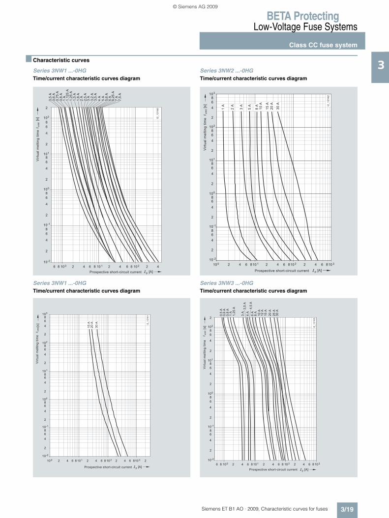
3■ Characteristic curves
Series 3NW1 ...-0HGTime/current characteristic curves diagram
Series 3NW2 ...-0HGTime/current characteristic curves diagram
Series 3NW1 ...-0HGTime/current characteristic curves diagram
Series 3NW3 ...-0HGTime/current characteristic curves diagram
Prospective short-circuit current
Vir
tua
l m
elt
ing
tim
et v
mt
210 0 64 86 8 210 1 64 8 210 2 4
p [A]
-210
2
4
6
8
-110
2
4
6
8
010
2
4
6
8
110
2
210
2
4
6
8
0,5
A0,6
A0,7
5 A
0,8
A1
A1
,12
5 A
1,2
5 A
1,5
A1,8
A2
A
3 A
4 A
5 A
5,6
A6
A6,2
5 A
7 A
7,5
A
2,5
A
3,2
A3,5
A
[s] I2
_1
21
60
Vir
tua
l m
elt
ing
tim
e
Prospective short-circuit current
t vm
t
210 0 64 810 1 2 64 810 2 2 64 810 3
p [A]
1 A
2 A
3 A
5 A
8 A
10
A
15
A
20
A
30
A
-210
2
4
68
-110
2
4
68
010
2
4
6
8
110
2
210
2
4
6
8
310
4
6
8
[s]
I2_
12
16
2
Prospective short-circuit current
Vir
tua
l m
elt
ing
tim
et v
mt 20
A1
5 A
30
A I2_
12
16
1
210 0 64 8 210 1 6 64 8 82 210 2 10 34
p [A]
-210
2
4
68
-110
2
4
68
010
2
4
68
110
2
210
310
2
4
6
8
4
68
[s]
Vir
tua
l m
elt
ing
tim
e
Prospective short-circuit current
t vm
t
210 0 64 86 8 210 1 64 8 210 2 6 8 10 34
p [A]
-210
2
4
68
-110
2
4
6
8
010
2
4
6
8
110
2
210
2
4
6
8
0,5
A0
,6 A
0,8
A1
A1
,25
A
3 A
3,5
A4
A4
,5 A
6 A
8 A
10
A1
2 A
15
A
20
A
25
A3
0 A
[s]
I2_
12
16
3
ET_B1_AO_Kennlinien.book Seite 19 Dienstag, 13. Oktober 2009 11:58 11
© Siemens AG 2009

BETA ProtectingLow-Voltage Fuse Systems
Class CC fuse system
3/20 Siemens ET B1 AO · 2009, Characteristic curves for fuses
3Series 3NW3 ...-0HGCurrent limitation diagram
210 1 64 8 10 2 2 64 2 48 10 3
p [A]
110
2
4
6
8
210
2
310
2
4
4
68
c[A
]
I2_
12
16
4
30 A25 A20 A15 A
2,8 A
1,25 A
ET_B1_AO_Kennlinien.book Seite 20 Dienstag, 13. Oktober 2009 11:58 11
© Siemens AG 2009
BETA ProtectingLow-Voltage Fuse Systems
LV HRC fuse links
3/21Siemens ET B1 AO · 2009, Characteristic curves for fuses
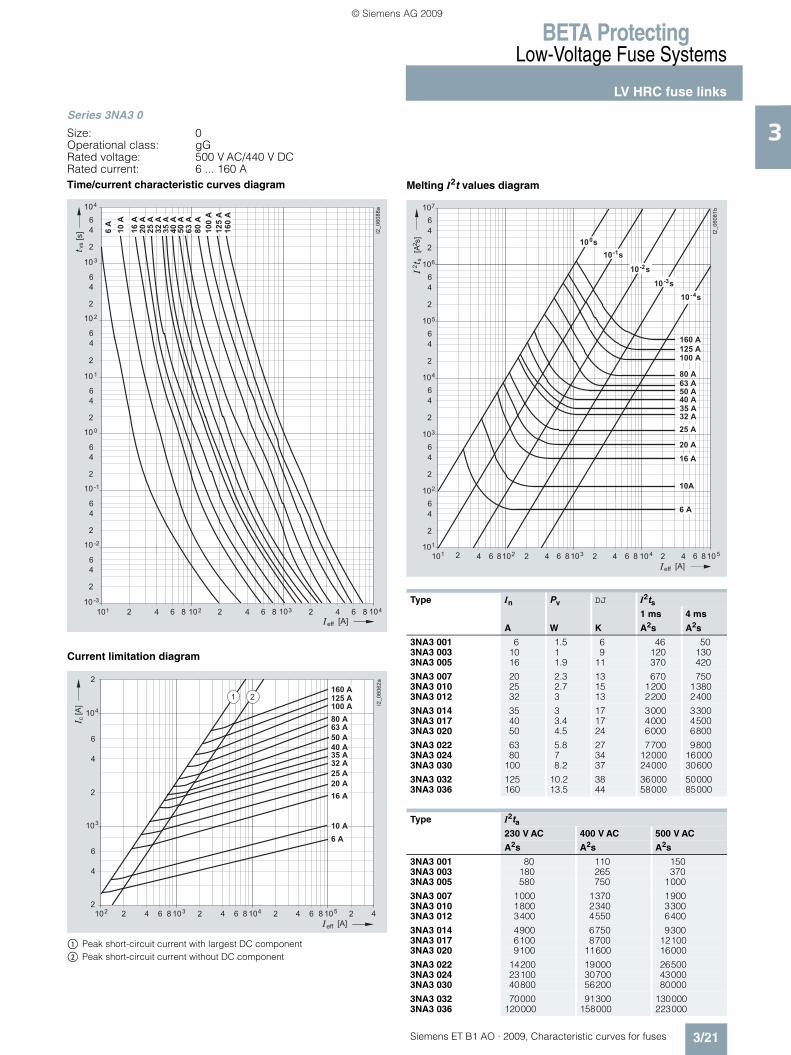
3Series 3NA3 0
Size: 0Operational class: gGRated voltage: 500 V AC/440 V DCRated current: 6 ... 160 ATime/current characteristic curves diagram
Current limitation diagram
$ Peak short-circuit current with largest DC component% Peak short-circuit current without DC component
Melting I2t values diagram
� �
� � �
�
�
�
� � �
�� � �� � �� � �� � �
�
�
�
� �
�
�
�
� �
�
�
�
�
�
�
�
� �
�
�
�
� �
�
�
�
� �
��������
� � ��
���
����
����
����
���
����
�����
����
�����
���
��
����
���
���
��
� � � � � �
���
��
� �� ��
�
�
�
�
� � � � �
� � � � �
�
�
�
�
� � � �
� � �
� � � �
� � � �
� � � �
� � �
� �
� � �
� � � �
� � �
�
� � �� � �
���
��
�
�� �� ��
�� �� ��
�� �
� � � �
� � �
��������
�
Type In Pv DJ I2ts1 ms 4 ms
A W K A2s A2s
3NA3 001 6 1.5 6 46 503NA3 003 10 1 9 120 1303NA3 005 16 1.9 11 370 420
3NA3 007 20 2.3 13 670 7503NA3 010 25 2.7 15 1200 13803NA3 012 32 3 13 2200 2400
3NA3 014 35 3 17 3000 33003NA3 017 40 3.4 17 4000 45003NA3 020 50 4.5 24 6000 6800
3NA3 022 63 5.8 27 7700 98003NA3 024 80 7 34 12000 160003NA3 030 100 8.2 37 24000 30600
3NA3 032 125 10.2 38 36000 500003NA3 036 160 13.5 44 58000 85000
Type I2ta230 V AC 400 V AC 500 V AC
A2s A2s A2s
3NA3 001 80 110 1503NA3 003 180 265 3703NA3 005 580 750 1000
3NA3 007 1000 1370 19003NA3 010 1800 2340 33003NA3 012 3400 4550 6400
3NA3 014 4900 6750 93003NA3 017 6100 8700 121003NA3 020 9100 11600 16000
3NA3 022 14200 19000 265003NA3 024 23100 30700 430003NA3 030 40800 56200 80000
3NA3 032 70000 91300 1300003NA3 036 120000 158000 223000
� � � � � � �� � �� � �� � �� �� � � �� ��
�
�
�
�
�
�
�
�
�
�
�
�
�
�
�
�
�
�
�
�
�
�
�
�
�
�������
�
�
�
�
�
� � � � �
� � � �
� � � �
� � �
� � �
� � � �
� � �
� � �
� � � �
� � � �
� � � � �
� � �
� � �
� �
� ���
� � ��
� � ��
� � �
� � ��
� � � � � �
��
�����
�
ET_B1_AO_Kennlinien.book Seite 21 Dienstag, 13. Oktober 2009 11:58 11
© Siemens AG 2009
BETA ProtectingLow-Voltage Fuse Systems
LV HRC fuse links
3/22 Siemens ET B1 AO · 2009, Characteristic curves for fuses
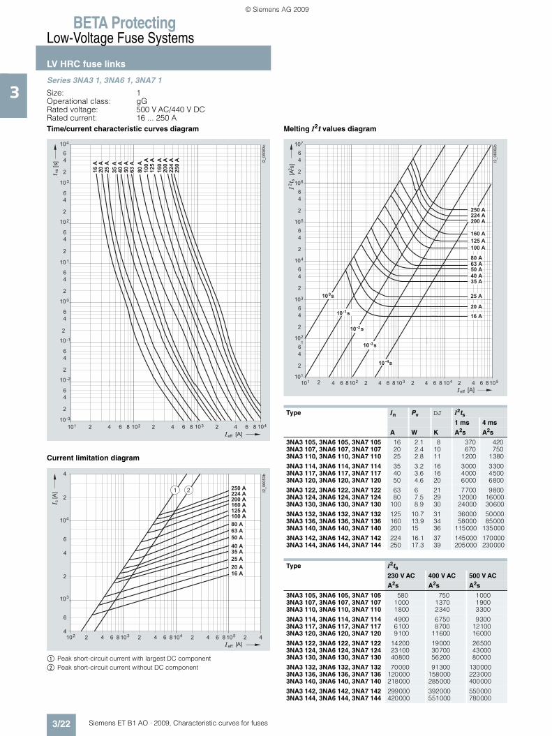
3Series 3NA3 1, 3NA6 1, 3NA7 1
Size: 1Operational class: gGRated voltage: 500 V AC/440 V DCRated current: 16 ... 250 ATime/current characteristic curves diagram
Current limitation diagram
$ Peak short-circuit current with largest DC component% Peak short-circuit current without DC component
Melting I2t values diagram
� �
� � �
�
�
�
� � �
�� � �� � �� � �� � �
�
�
�
� �
�
�
�
� �
�
�
�
�
�
�
�
� �
�
�
�
� �
�
�
�
� �
��������
� � ��
����
����
���
����
�����
����
�����
��
����
���
���
�����
�����
����
��
� � � � � �
���
��
� �� ��
�
�
�
� � � � �
� � � � �
�
�
�
�
� � � �
� � � �
� � � �
� � �
� �
� � �
� � � �
�
� � �� � �
���
��
�
�� �� ��
�� �� ��
�� �
� � � �
� � �
���������
� � � � �
� � � � �
� � � � �
Type In Pv DJ I2ts1 ms 4 ms
A W K A2s A2s
3NA3 105, 3NA6 105, 3NA7 105 16 2.1 8 370 4203NA3 107, 3NA6 107, 3NA7 107 20 2.4 10 670 7503NA3 110, 3NA6 110, 3NA7 110 25 2.8 11 1200 1380
3NA3 114, 3NA6 114, 3NA7 114 35 3.2 16 3000 33003NA3 117, 3NA6 117, 3NA7 117 40 3.6 16 4000 45003NA3 120, 3NA6 120, 3NA7 120 50 4.6 20 6000 6800
3NA3 122, 3NA6 122, 3NA7 122 63 6 21 7700 98003NA3 124, 3NA6 124, 3NA7 124 80 7.5 29 12000 160003NA3 130, 3NA6 130, 3NA7 130 100 8.9 30 24000 30600
3NA3 132, 3NA6 132, 3NA7 132 125 10.7 31 36000 500003NA3 136, 3NA6 136, 3NA7 136 160 13.9 34 58000 850003NA3 140, 3NA6 140, 3NA7 140 200 15 36 115000 135000
3NA3 142, 3NA6 142, 3NA7 142 224 16.1 37 145000 1700003NA3 144, 3NA6 144, 3NA7 144 250 17.3 39 205000 230000
Type I2ta230 V AC 400 V AC 500 V AC
A2s A2s A2s
3NA3 105, 3NA6 105, 3NA7 105 580 750 10003NA3 107, 3NA6 107, 3NA7 107 1000 1370 19003NA3 110, 3NA6 110, 3NA7 110 1800 2340 3300
3NA3 114, 3NA6 114, 3NA7 114 4900 6750 93003NA3 117, 3NA6 117, 3NA7 117 6100 8700 121003NA3 120, 3NA6 120, 3NA7 120 9100 11600 16000
3NA3 122, 3NA6 122, 3NA7 122 14200 19000 265003NA3 124, 3NA6 124, 3NA7 124 23100 30700 430003NA3 130, 3NA6 130, 3NA7 130 40800 56200 80000
3NA3 132, 3NA6 132, 3NA7 132 70000 91300 1300003NA3 136, 3NA6 136, 3NA7 136 120000 158000 2230003NA3 140, 3NA6 140, 3NA7 140 218000 285000 400000
3NA3 142, 3NA6 142, 3NA7 142 299000 392000 5500003NA3 144, 3NA6 144, 3NA7 144 420000 551000 780000
� � � � � � �� � �� � �� � �� �� � � �� ��
�
�
�
�
�
�
�
�
�
�
�
�
�
�
�
�
�
�
�
�
�
�
�
�
�
��������
�
�
�
�
�
� � ��
� ���
� � ��
� � �
� � ��
� � � � �
� � � �
� � � �
� � �
� � �
� � � �
� �
� � �
� � � �
� � � �
� � � � �
� � � � �
� � � � �
� � � �
� � � � � �
��
�����
�
ET_B1_AO_Kennlinien.book Seite 22 Dienstag, 13. Oktober 2009 11:58 11
© Siemens AG 2009
BETA ProtectingLow-Voltage Fuse Systems
LV HRC fuse links
3/23Siemens ET B1 AO · 2009, Characteristic curves for fuses
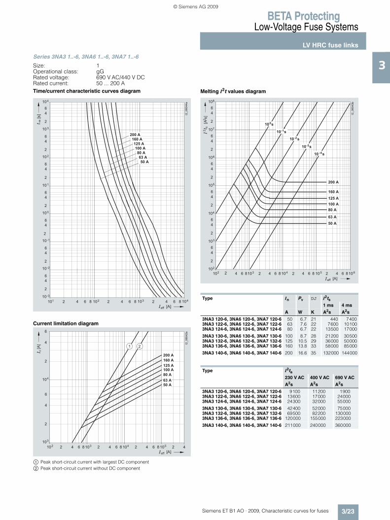
3Series 3NA3 1..-6, 3NA6 1..-6, 3NA7 1..-6
Size: 1Operational class: gGRated voltage: 690 V AC/440 V DCRated current: 50 ... 200 ATime/current characteristic curves diagram
Current limitation diagram
$ Peak short-circuit current with largest DC component% Peak short-circuit current without DC component
Melting I2t values diagram
� �
� � �
�
�
�
� � �
�� � �� � �� � �� � �
�
�
�
� �
�
�
�
� �
�
�
�
�
�
�
�
� �
�
�
�
� �
�
�
�
� �
��������
� � ��
� � � � �
� � � � �
� � � �
� � � � �
� � � �
� � �
� � �
��
� � � � � �
���
��
� �� ��
�
� � � � �
� � � � �
�
�
�
�
� � � �
� � �
�
� � �� � �
���
��
�
�� �� ��
�� �� ��
�� �
� � � �
� � �
��������
�
� � � � �
�
�
Type In Pv DJ I2ts1 ms 4 ms
A W K A2s A2s
3NA3 120-6, 3NA6 120-6, 3NA7 120-6 50 6.7 21 440 74003NA3 122-6, 3NA6 122-6, 3NA7 122-6 63 7.6 22 7600 101003NA3 124-6, 3NA6 124-6, 3NA7 124-6 80 6.7 22 13500 17000
3NA3 130-6, 3NA6 130-6, 3NA7 130-6 100 8.7 28 21200 305003NA3 132-6, 3NA6 132-6, 3NA7 132-6 125 10.5 29 36000 500003NA3 136-6, 3NA6 136-6, 3NA7 136-6 160 13.8 33 58000 85000
3NA3 140-6, 3NA6 140-6, 3NA7 140-6 200 16.6 35 132000 144000
Type I2ta230 V AC 400 V AC 690 V AC
A2s A2s A2s
3NA3 120-6, 3NA6 120-6, 3NA7 120-6 9100 11200 19003NA3 122-6, 3NA6 122-6, 3NA7 122-6 13600 17000 240003NA3 124-6, 3NA6 124-6, 3NA7 124-6 24300 32000 55000
3NA3 130-6, 3NA6 130-6, 3NA7 130-6 42400 52000 750003NA3 132-6, 3NA6 132-6, 3NA7 132-6 69500 82200 1300003NA3 136-6, 3NA6 136-6, 3NA7 136-6 120000 155000 223000
3NA3 140-6, 3NA6 140-6, 3NA7 140-6 211000 240000 360000
� � � � �� � �� � �� � �� � �� �� � � �� ��
�
�
�
�
�
�
�
�
�
�
�
�
�
�
�
�
�
�
�
�
�
�
�
�
�
��������
�
�
�
�
�
�
� ���
� � ��
� � ��
� � �
� � ��
� � � � �
� � � �
� � � �
� � �
� � �
� � � � �
� � � � �
� � � � � �
��
�����
�
ET_B1_AO_Kennlinien.book Seite 23 Dienstag, 13. Oktober 2009 11:58 11
© Siemens AG 2009
BETA ProtectingLow-Voltage Fuse Systems
LV HRC fuse links
3/24 Siemens ET B1 AO · 2009, Characteristic curves for fuses
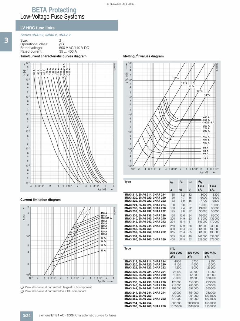
3Series 3NA3 2, 3NA6 2, 3NA7 2
Size: 2Operational class: gGRated voltage: 500 V AC/440 V DCRated current: 35 ... 400 ATime/current characteristic curves diagram
Current limitation diagram
$ Peak short-circuit current with largest DC component% Peak short-circuit current without DC component
Melting I2t values diagram
��� ��
�
� � �
�
�
�
� � �
�� ��
� � �� ��
� � �
�
�
�
� �
�
�
�
� �
�
�
�
�
�
�
�
� �
�
�
�
� �
�
�
�
� �
��������
���
���
����
�����
��
��
� � � � � �
���
����
�����
�����
�����
����
������
��
�����
��
� �� ��
�
� � � � �
� � � � �
�
�
�
�
� � � �
� � �
� �
�
� � �� � �
���
��
�
�� �� ��
�� �� ��
�� �
� � � �
� � �
��������
�
� � � � �
� � � � �
� � � �
�
� � � � � �
� �
� � � � � �
Type In Pv DJ I2ts1 ms 4 ms
A W K A2s A2s
3NA3 214, 3NA6 214, 3NA7 214 35 3.2 12 3000 33003NA3 220, 3NA6 220, 3NA7 220 50 4.7 16 6000 68003NA3 222, 3NA6 222, 3NA7 222 63 5.9 16 7700 9800
3NA3 224, 3NA6 224, 3NA7 224 80 6.8 21 12000 160003NA3 230, 3NA6 230, 3NA7 230 100 7.4 22 24000 306003NA3 232, 3NA6 232, 3NA7 232 125 9.8 27 36000 50000
3NA3 236, 3NA6 236, 3NA7 236 160 12.6 34 58000 850003NA3 240, 3NA6 240, 3NA7 240 200 14.9 33 115000 1350003NA3 242, 3NA6 242, 3NA7 242 224 15.4 31 145000 170000
3NA3 244, 3NA6 244, 3NA7 244 250 17.9 38 205000 2300003NA3 250, 3NA6 250 300 19.4 34 361000 4330003NA3 252, 3NA6 252, 3NA7 252 315 21.4 35 361000 433000
3NA3 254, 3NA6 254 355 26.0 49 441000 5380003NA3 260, 3NA6 260, 3NA7 260 400 27.5 52 529000 676000
Type I2ta230 V AC 400 V AC 500 V AC
A2s A2s A2s
3NA3 214, 3NA6 214, 3NA7 214 4900 6750 93003NA3 220, 3NA6 220, 3NA7 220 9100 11600 160003NA3 222, 3NA6 222, 3NA7 222 14200 19000 26500
3NA3 224, 3NA6 224, 3NA7 224 23100 30700 430003NA3 230, 3NA6 230, 3NA7 230 40800 56200 800003NA3 232, 3NA6 232, 3NA7 232 70000 91300 130000
3NA3 236, 3NA6 236, 3NA7 236 120000 158000 2230003NA3 240, 3NA6 240, 3NA7 240 218000 285000 4000003NA3 242, 3NA6 242, 3NA7 242 299000 392000 550000
3NA3 244, 3NA6 244, 3NA7 244 420000 551000 7800003NA3 250, 3NA6 250 670000 901000 12750003NA3 252, 3NA6 252, 3NA7 252 670000 901000 1275000
3NA3 254, 3NA6 254 800000 1060000 15000003NA3 260, 3NA6 260, 3NA7 260 1155000 1515000 2150000
� � � � �� � �� � �� � �� � �� �� � � �� ��
�
�
�
�
�
�
�
�
�
�
�
�
�
�
�
�
�
�
�
�
�
�
�
�
�
����� ��
�
�
�
�
�
�
� � � � �
� � � �
� � � �
� � �
� � �
� � � � �
� �
� ���
� � ��
� � ��
� � �
� � ��
� � � � �
� � � � �
� � � �
� � � � � �
� �
� � � � �
� � � � � �
��
�����
�
ET_B1_AO_Kennlinien.book Seite 24 Dienstag, 13. Oktober 2009 11:58 11
© Siemens AG 2009
BETA ProtectingLow-Voltage Fuse Systems
LV HRC fuse links
3/25Siemens ET B1 AO · 2009, Characteristic curves for fuses
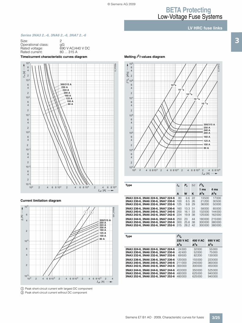
3Series 3NA3 2..-6, 3NA6 2..-6, 3NA7 2..-6
Size: 2Operational class: gGRated voltage: 690 V AC/440 V DCRated current: 80 ... 315 ATime/current characteristic curves diagram
Current limitation diagram
$ Peak short-circuit current with largest DC component% Peak short-circuit current without DC component
Melting I2t values diagram
� � �
� � �
�
�
�
� � �
�� � �� � �� � �� � �
�
�
�
� �
�
�
�
� �
�
�
�
�
�
�
�
� �
�
�
�
� �
�
�
�
� �
��� ����
� � ��
� � � �
� � � � �
� � � � �
� � � � �
� � � �
� � � � �
� � � �
� � � � � �
��
� � � � � �
���
I201
_0
75
40
b
10 2 2 64 108
10
2
4
6
160 A
100 A
2
4
6
4
125 A
c
[A]
[A]
105
10 3
3 2 64 108 4 2 64 108 5 2 4
80 A
200 A224 A250 A
1 2
300/315 A
eff
Type In Pv DJ I2ts1 ms 4 ms
A W K A2s A2s
3NA3 224-6, 3NA6 224-6, 3NA7 224-6 80 6.6 22 13500 170003NA3 230-6, 3NA6 230-6, 3NA7 230-6 100 8.5 26 21200 305003NA3 232-6, 3NA6 232-6, 3NA7 232-6 125 9.8 29 36000 50000
3NA3 236-6, 3NA6 236-6, 3NA7 236-6 160 13.3 31 58000 850003NA3 240-6, 3NA6 240-6, 3NA7 240-6 200 16.1 33 132000 1440003NA3 242-6, 3NA6 242-6, 3NA7 242-6 224 19.9 38 125000 162000
3NA3 244-6, 3NA6 244-6, 3NA7 244-6 250 23 44 180000 2150003NA3 250-6, 3NA6 250-6, 3NA7 250-6 300 25.6 38 300000 3800003NA3 252-6, 3NA6 252-6, 3NA7 252-6 315 28.2 42 300000 380000
Type I2ta230 V AC 400 V AC 690 V AC
A2s A2s A2s
3NA3 224-6, 3NA6 224-6, 3NA7 224-6 24300 32000 550003NA3 230-6, 3NA6 230-6, 3NA7 230-6 42400 52000 750003NA3 232-6, 3NA6 232-6, 3NA7 232-6 69500 82200 130000
3NA3 236-6, 3NA6 236-6, 3NA7 236-6 120000 155000 2230003NA3 240-6, 3NA6 240-6, 3NA7 240-6 211000 240000 3600003NA3 242-6, 3NA6 242-6, 3NA7 242-6 300000 300000 450000
3NA3 244-6, 3NA6 244-6, 3NA7 244-6 453000 350000 5250003NA3 250-6, 3NA6 250-6, 3NA7 250-6 480000 625000 9400003NA3 252-6, 3NA6 252-6, 3NA7 252-6 480000 625000 940000
� � � � �� � �� � �� � �� � �� �� � � �� ��
�
�
�
�
�
�
�
�
�
�
�
�
�
�
�
�
�
�
�
�
�
�
�
�
�
��� ���
�
�
�
�
�
�
� � � � �
� � � �
� � � �
� � � � �
� � � � �
� ���
� � ��
� � ��
� � �
� � ��
� � � � �
� � � �
� � � � � �
� � � � � �
��
�����
�
ET_B1_AO_Kennlinien.book Seite 25 Dienstag, 13. Oktober 2009 11:58 11
© Siemens AG 2009

BETA ProtectingLow-Voltage Fuse Systems
LV HRC fuse links
3/26 Siemens ET B1 AO · 2009, Characteristic curves for fuses
3Series 3NA3 3
Size: 3Operational class: gGRated voltage: 500 V AC/440 V DCRated current: 200 ... 630 ATime/current characteristic curves diagram
Current limitation diagram
$ Peak short-circuit current with largest DC component% Peak short-circuit current without DC component
Melting I2t values diagram
� � �
� � �
�
�
�
� � �
�� � �� � �� � �� � �
�
�
�
� �
�
�
�
� �
�
�
�
�
�
�
�
� �
�
�
�
� �
�
�
�
� �
�������
� � ��
� � � �
� � � �
� � � �
� � � � �
� �
� � � � � �
� � � �
� � � � �
��
� � � � � �
���
� � � � �
��
� �� ��
�
�
�
�
�
�
�
�
� � � � � �
���
��
�� �� ��
�� �� ��
�
�������
� � � � �
� � � �
� � � � � �
� �
� � � � �
� � � �
� � � �
� � � � �
� � � � �
Type In Pv DJ I2ts1 ms 4 ms
A W K A2s A2s
3NA3 340 200 14.9 32 115000 1350003NA3 342 224 15.4 31 145000 1700003NA3 344 250 17.9 36 205000 230000
3NA3 350 300 19.4 19 361000 4330003NA3 352 315 21.4 22 361000 4330003NA3 354 355 26.0 26 441000 538000
3NA3 360 400 27.5 28 529000 6760003NA3 362 425 26.5 34 650000 9700003NA3 365 500 36.5 41 785000 1270000
3NA3 372 630 44.0 50 1900000 2700000
Type I2ta230 V AC 400 V AC 500 V AC
A2s A2s A2s
3NA3 340 218000 285000 4000003NA3 342 299000 392000 5500003NA3 344 420000 551000 780000
3NA3 350 670000 901000 12750003NA3 352 670000 901000 12750003NA3 354 800000 1060000 1500000
3NA3 360 1155000 1515000 21500003NA3 362 1515000 1856000 22700003NA3 365 1915000 2260000 2700000
3NA3 372 3630000 4340000 5400000
� � � � �� � �� � �� � �� � �� �� � � �� ��
�
�
�
�
�
�
�
�
�
�
�
�
�
�
�
�
�
�
�
�
�
�
�
�
�
����� ��
�
�
�
�
�
�
� � � �
� � � �
� � � �
� � � �
� � � � �
� �
� � � � � �
� � � � � �
��
�����
�
�
� ���
� � ��
� � ��
� � �
� � ��
� � � � �
� � � � �
ET_B1_AO_Kennlinien.book Seite 26 Dienstag, 13. Oktober 2009 11:58 11
© Siemens AG 2009

BETA ProtectingLow-Voltage Fuse Systems
LV HRC fuse links
3/27Siemens ET B1 AO · 2009, Characteristic curves for fuses
3Series 3NA3 3..-6
Size: 3Operational class: gGRated voltage: 690 V AC/440 V DCRated current: 250 ... 500 ATime/current characteristic curves diagram
Current limitation diagram
$ Peak short-circuit current with largest DC component% Peak short-circuit current without DC component
Melting I2t values diagram
� � �
� � �
�
�
�
� � �
�� � �� � �� � �� � �
�
�
�
� �
�
�
�
� �
�
�
�
�
�
�
�
� �
�
�
�
� �
�
�
�
� �
��� ����
� � ��
� � � �
� � � � �
� �
� � �
� � � �
� � � �
��
� � � � � �
���
�
�
�
�
�
�
�
� � � � � �
���
��
���� � �� ��
�� �
��� ����
� � � �
� �
�
� � �
� � � � �
� � � �
� � � �
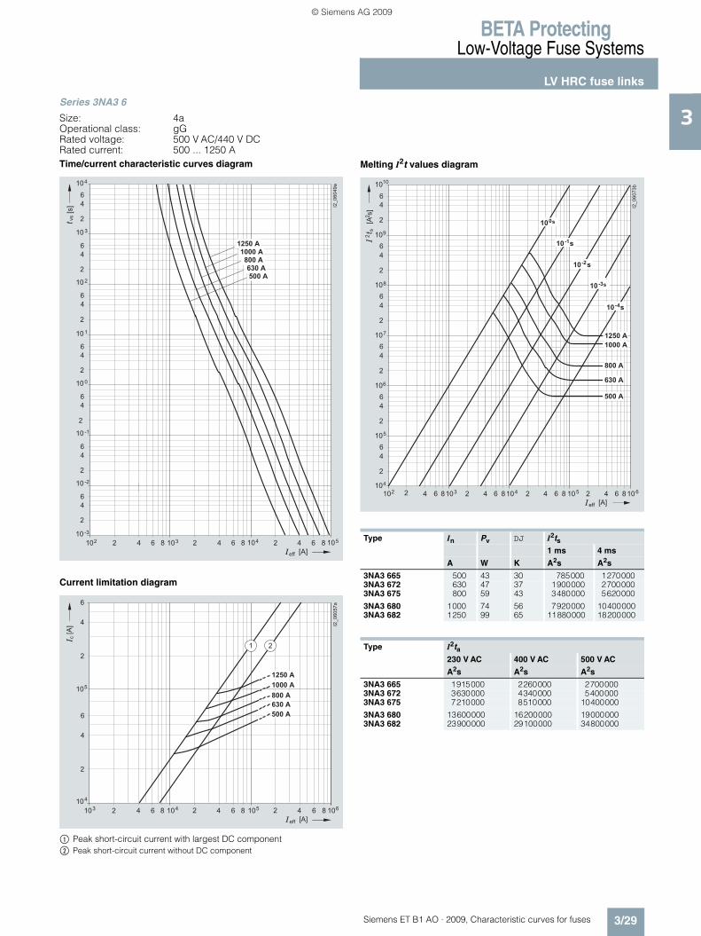
Type In Pv DJ I2ts1 ms 4 ms
A W K A2s A2s
3NA3 344-6 250 23 44 180000 2150003NA3 352-6 315 28.2 42 300000 3800003NA3 354-6 355 32.5 40 380000 470000
3NA3 360-6 400 33.2 42 540000 6750003NA3 362-6 425 35.3 44 625000 7650003NA3 365-6 500 43.5 52 810000 1000000
Type I2ta230 V AC 400 V AC 690 V AC
A2s A2s A2s
3NA3 344-6 453000 350000 5250003NA3 352-6 480000 625000 9400003NA3 354-6 585000 760000 1150000
3NA3 360-6 847000 1100000 16500003NA3 362-6 925000 1200000 18000003NA3 365-6 1300000 1700000 2500000
� � � � �� � �� � �� � �� � �� �� � � �� ��
�
�
�
�
�
�
�
�
�
�
�
�
�
�
�
�
�
�
�
�
�
�
�
�
�
��� ����
�
�
�
�
�
�
� ���
� � ��
� � ��
� � �
� � ��
� �
� � �
� � � �
� � � � �
� � � �
� � � � � �
��
�����
�
� � � �
ET_B1_AO_Kennlinien.book Seite 27 Dienstag, 13. Oktober 2009 11:58 11
© Siemens AG 2009

BETA ProtectingLow-Voltage Fuse Systems
LV HRC fuse links
3/28 Siemens ET B1 AO · 2009, Characteristic curves for fuses
3Series 3NA3 4
Size: 4 (IEC design)Operational class: gGRated voltage: 500 V AC/440 V DCRated current: 630 ... 1250 ATime/current characteristic curves diagram
Current limitation diagram
$ Peak short-circuit current with largest DC component% Peak short-circuit current without DC component
Melting I2t values diagram
��
� � �
� � �
�
�
�
� � �
�� � �� � �� � �� � �
�
�
�
� �
�
�
�
� �
�
�
�
�
�
�
�
� �
�
�
�
� �
�
�
�
� �
��� ����
� � ��
� � � � �
� � � � � � �
� � � � � � � �
� � � � � � � � �
� � � � � �
���
��
� �� ��
�
�
�
�
�
�
� � � � � �
���
��
�
�� �� ��
�
��� ����
�
�
� � � �
�
� � � � �
� � � � � �
� � � � �
� � � � ��
Type In Pv DJ I2ts1 ms 4 ms
A W K A2s A2s
3NA3 472 630 47 37 1900000 27000003NA3 475 800 59 43 3480000 5620000
3NA3 480 1000 74 56 7920000 104000003NA3 482 1250 99 65 11880000 18200000
Type I2ta230 V AC 400 V AC 500 V AC
A2s A2s A2s
3NA3 472 3630000 4340000 54000003NA3 475 7210000 8510000 10400000
3NA3 480 13600000 16200000 190000003NA3 482 23900000 29100000 34800080
� � � � �� � �� � �� � �� � �� �� � � �� ��
�
�
�
�
�
�
�
�
�
�
�
�
�
�
�
�
�
�
�
�
�
�
�
�
�
��� ����
�
�
�
�
�
�
� � � � �
� � � � � �
� � �
� � ��
� � ��
� � ��
� ���
� � � � �
� � � �
� � � � � �
��
�����
�
ET_B1_AO_Kennlinien.book Seite 28 Dienstag, 13. Oktober 2009 11:58 11
© Siemens AG 2009
BETA ProtectingLow-Voltage Fuse Systems
LV HRC fuse links
3/29Siemens ET B1 AO · 2009, Characteristic curves for fuses
3Series 3NA3 6
Size: 4aOperational class: gGRated voltage: 500 V AC/440 V DCRated current: 500 ... 1250 ATime/current characteristic curves diagram
Current limitation diagram
$ Peak short-circuit current with largest DC component% Peak short-circuit current without DC component
Melting I2t values diagram
� � �
� � �
�
�
�
� � �
�� � �� � �� � �� � �
�
�
�
� �
�
�
�
� �
�
�
�
�
�
�
�
� �
�
�
�
� �
�
�
�
� �
��������
� � ��
� � � � �
� � � � � �
� � � � �
� � � �
� � � �
��
� � � � � �
���
��
� �� ��
�
�
�
�
�
�
� � � � � �
���
��
�
�� �� ��
�
������ �
�
�
� � � � �
� � � � � �
� � � � �
� � � � ��
� � � �
�
� � � �
Type In Pv DJ I2ts1 ms 4 ms
A W K A2s A2s
3NA3 665 500 43 30 785000 12700003NA3 672 630 47 37 1900000 27000003NA3 675 800 59 43 3480000 5620000
3NA3 680 1000 74 56 7920000 104000003NA3 682 1250 99 65 11880000 18200000
Type I2ta230 V AC 400 V AC 500 V AC
A2s A2s A2s
3NA3 665 1915000 2260000 27000003NA3 672 3630000 4340000 54000003NA3 675 7210000 8510000 10400000
3NA3 680 13600000 16200000 190000003NA3 682 23900000 29100000 34800000
� � � � �� � �� � �� � �� � �� �� � � �� ��
�
�
�
�
�
�
�
�
�
�
�
�
�
�
�
�
�
�
�
�
�
�
�
�
�
����� ��
�
�
�
�
�
�
� � � �
� � � �
� � �
� � ��
� � ��
� � � �
� � � �
� � � � � �
� � � � �
� � � � �
� � � � � �
��
�����
�
ET_B1_AO_Kennlinien.book Seite 29 Dienstag, 13. Oktober 2009 11:58 11
© Siemens AG 2009

BETA ProtectingLow-Voltage Fuse Systems
LV HRC fuse links
3/30 Siemens ET B1 AO · 2009, Characteristic curves for fuses
3Series 3NA3 8, 3NA6 8, 3NA7 8
Size: 000, 00Operational class: gGRated voltage: 500 V AC/250 V DCRated current: 2 ... 160 ATime/current characteristic curves diagram
Current limitation diagram
$ Peak short-circuit current with largest DC component% Peak short-circuit current without DC component
Melting I2t values diagram
Table see page 3/31.
��� � �
� � �
�
�
�
� � �
�� � �� � �� � �� � �
�
�
�
� �
�
�
�
� �
�
�
�
�
�
�
�
� �
�
�
�
� �
�
�
�
� �
����� �
����
���
���
����
����
���
���
��
����
���
���
����
�����
����
�����
���
��
� � � � � �
���
��
� �� ��
�
�
�
�
� � � � �
� � � � �
�
�
�
�
� � � �
� � �
� � � �
� � � �
� � �
� � � �
� � �
� �
� � �
� � � �
� � �
� � �
�
� � �� � �
��� �
�
�
��
�� �� ��
�� �� ��
�� �
�
� � � �
� � �
��������
� � � � � � �� �
�� � �� �
��
�� � � ��
��
�
�
�
�
� � � � �
� � � �
� � � � �
� � � �
� � �
� � �
� � � �
� �
� � �
� � �
� � � �
� � � �
� � � �
� � �
� � �
� ���
� � ��
� � ��
� � �
� � ��
�
�
�
�
�
�
�
�
�
�
�
�
�
�
�
�
�
�
�
�
�
��������
� � �
� � � � � �
��
�����
�
�
�
�
�
�
�
ET_B1_AO_Kennlinien.book Seite 30 Dienstag, 13. Oktober 2009 11:58 11
© Siemens AG 2009

BETA ProtectingLow-Voltage Fuse Systems
LV HRC fuse links
3/31Siemens ET B1 AO · 2009, Characteristic curves for fuses
3Series 3NA3 8, 3NA6 8, 3NA7 8
Size: 000, 00Operational class: gGRated voltage: 500 V AC/250 V DCRated current: 2 ... 160 A
Type In Pv DJ I2ts I2ta1 ms 4 ms 230 V AC 400 V AC 500 V AC
A W K A2s A2s A2s A2s A2s
3NA3 802, 3NA6 802, 3NA7 802 2 1.3 8 2 2 4 6 93NA3 804, 3NA6 804, 3NA7 804 4 0.9 6 11 13 18 22 273NA3 801, 3NA6 801, 3NA7 801 6 1.3 8 46 50 80 110 150
3NA3 803, 3NA6 803, 3NA7 803 10 1 8 120 130 180 265 3703NA3 805, 3NA6 805, 3NA7 805 16 1.7 11 370 420 580 750 10003NA3 807, 3NA6 807, 3NA7 807 20 2 15 670 750 1000 1370 1900
3NA3 810, 3NA6 810, 3NA7 810 25 2.3 17 1 200 1380 1800 2340 33003NA3 812, 3NA6 812, 3NA7 812 32 2.6 18 2200 2400 3400 4550 64003NA3 814, 3NA3 814-7, 3NA6 814, 3NA7 814 35 2.7 21 3000 3300 4900 6750 9300
3NA3 817, 3NA6 817, 3NA7 817 40 3.1 24 4000 4500 6100 8700 121003NA3 820, 3NA3 820-7, 3NA6 820, 3NA7 820 50 3.8 25 6000 6800 9100 11600 160003NA3 822, 3NA3 822-7, 3NA6 822, 3NA7 822 63 4.6 28 7700 9800 14200 19000 26500
3NA3 824, 3NA3 824-7, 3NA6 824, 3NA6 824-7, 3NA7 824, 3NA7 824-7
80 5.8 33 12000 16000 23100 30700 43000
3NA3 830, 3NA3 830-7, 3NA6 830, 3NA6 830-7, 3NA7 830, 3NA7 830-7
100 6.6 34 24000 30600 40800 56200 80000
3NA3 832, 3NA6 832, 3NA7 832 125 8.9 44 36000 50000 70000 91300 1300003NA3 832-8 125 7.2 30 46000 45000 97000 117000 1340003NA3 836, 3NA6 836, 3NA7 836 160 11.3 52 58000 85000 120000 158000 2230003NA3 836-8 160 9 34 89000 84800 137000 166000 --
ET_B1_AO_Kennlinien.book Seite 31 Dienstag, 13. Oktober 2009 11:58 11
© Siemens AG 2009
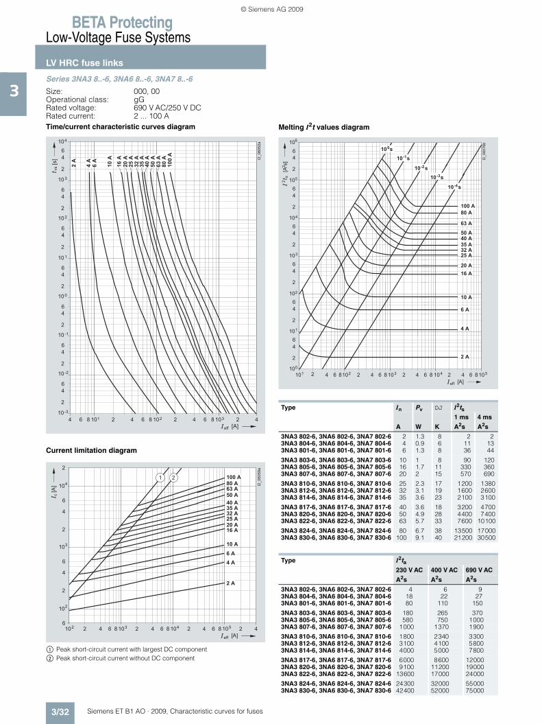
BETA ProtectingLow-Voltage Fuse Systems
LV HRC fuse links
3/32 Siemens ET B1 AO · 2009, Characteristic curves for fuses
3Series 3NA3 8..-6, 3NA6 8..-6, 3NA7 8..-6
Size: 000, 00 Operational class: gGRated voltage: 690 V AC/250 V DCRated current: 2 ... 100 ATime/current characteristic curves diagram
Current limitation diagram
$ Peak short-circuit current with largest DC component% Peak short-circuit current without DC component
Melting I2t values diagram
��� � �
� � �
�
�
�
� � �
�� � �� � �� � �� � �
�
�
�
� �
�
�
�
� �
�
�
�
�
�
�
�
� �
�
�
�
� �
�
�
�
� �
��������
����
����
����
���
���
��
���
���
���
����
�����
���
���
����
��
� � � � � �
���
��
� �� ��
�
�
�
�
�
�
� � �� � �
���
�
�� �� ��
�� �� ��
�� �
��������
�
�
�
�
�
��
�
� � � � � �
� � � �
� � �
� � �
� � �
� � �
� � � �
� � � �
� � � �
� � �
� � � �
� � �
� � �
� �
Type In Pv DJ I2ts1 ms 4 ms
A W K A2s A2s
3NA3 802-6, 3NA6 802-6, 3NA7 802-6 2 1.3 8 2 23NA3 804-6, 3NA6 804-6, 3NA7 804-6 4 0.9 6 11 133NA3 801-6, 3NA6 801-6, 3NA7 801-6 6 1.3 8 36 44
3NA3 803-6, 3NA6 803-6, 3NA7 803-6 10 1 8 90 1203NA3 805-6, 3NA6 805-6, 3NA7 805-6 16 1.7 11 330 3603NA3 807-6, 3NA6 807-6, 3NA7 807-6 20 2 15 570 690
3NA3 810-6, 3NA6 810-6, 3NA7 810-6 25 2.3 17 1200 13803NA3 812-6, 3NA6 812-6, 3NA7 812-6 32 3.1 19 1600 26003NA3 814-6, 3NA6 814-6, 3NA7 814-6 35 3.6 23 2100 3100
3NA3 817-6, 3NA6 817-6, 3NA7 817-6 40 3.6 18 3200 47003NA3 820-6, 3NA6 820-6, 3NA7 820-6 50 4.9 28 4400 74003NA3 822-6, 3NA6 822-6, 3NA7 822-6 63 5.7 33 7600 10100
3NA3 824-6, 3NA6 824-6, 3NA7 824-6 80 6.7 38 13500 170003NA3 830-6, 3NA6 830-6, 3NA7 830-6 100 9.1 40 21200 30500
Type I2ta230 V AC 400 V AC 690 V AC
A2s A2s A2s
3NA3 802-6, 3NA6 802-6, 3NA7 802-6 4 6 93NA3 804-6, 3NA6 804-6, 3NA7 804-6 18 22 273NA3 801-6, 3NA6 801-6, 3NA7 801-6 80 110 150
3NA3 803-6, 3NA6 803-6, 3NA7 803-6 180 265 3703NA3 805-6, 3NA6 805-6, 3NA7 805-6 580 750 10003NA3 807-6, 3NA6 807-6, 3NA7 807-6 1000 1370 1900
3NA3 810-6, 3NA6 810-6, 3NA7 810-6 1800 2340 33003NA3 812-6, 3NA6 812-6, 3NA7 812-6 3100 4100 58003NA3 814-6, 3NA6 814-6, 3NA7 814-6 4000 5000 7800
3NA3 817-6, 3NA6 817-6, 3NA7 817-6 6000 8600 120003NA3 820-6, 3NA6 820-6, 3NA7 820-6 9100 11200 190003NA3 822-6, 3NA6 822-6, 3NA7 822-6 13600 17000 24000
3NA3 824-6, 3NA6 824-6, 3NA7 824-6 24300 32000 550003NA3 830-6, 3NA6 830-6, 3NA7 830-6 42400 52000 75000
� � � � � � �� � �� � �� � �� �� � � �� ��
�
�
�
�
�
�
�
�
�
�
�
�
�
�
�
�
�
�
�
�
�
�
�
�
�
����� ��
�
�
�
�
�
�
� � �
� ���
� � ��
� � ��
� � �
� � ��
� � �
� � �
� � � �
� � � �
� � � �
� � �
� � �
� �
� � � �
� � �
� � �
� � � �
� � � � �
� � � � � �
��
�����
�
ET_B1_AO_Kennlinien.book Seite 32 Dienstag, 13. Oktober 2009 11:58 11
© Siemens AG 2009

BETA ProtectingLow-Voltage Fuse Systems
LV HRC fuse links
3/33Siemens ET B1 AO · 2009, Characteristic curves for fuses
3Series 3NA6 1..-4
Size: 1Operational class: gGRated voltage: 400 V ACRated current: 35 ... 250 ATime/current characteristic curves diagram
Current limitation diagram
$ Peak short-circuit current with largest DC component% Peak short-circuit current without DC component
Melting I2t values diagram
��� � ��
� � �
�
�
�
� � �
�� � �� � �� � �� � �
�
�
�
� �
�
�
�
� �
�
�
�
�
�
�
�
� �
�
�
�
� �
�
�
�
� �
����
��
����
���
���
����
�����
����
�����
��
� � � � � �
��� �����
�����
����
��
� �� ��
�
�
�
�
�
�
�
�
�
� � � � � �
���
��
��
�� �� ��
�� �� ��
�� �
����
� � �
� � � � �
� � � � �
� � � �
� � � � �
� � � � �
� � � �
� � � �
�
� � � �
� � �
� �
Type In Pv DJ
A W K
3NA6 114-4 35 3.2 163NA6 117-4 40 3.6 163NA6 120-4 50 4.6 20
3NA6 122-4 63 6.0 213NA6 124-4 80 7.5 293NA6 130-4 100 8.9 30
3NA6 132-4 125 10.7 313NA6 136-4 160 13.9 343NA6 140-4 200 15.0 36
3NA6 142-4 224 16.1 373NA6 144-4 250 17.3 39
Type I2ts I2ta1 ms 4 ms 230 V AC 400 V AC
A2s A2s A2s A2s
3NA6 114-4 3000 3300 4900 67503NA6 117-4 4000 4500 6100 87003NA6 120-4 6000 6800 9100 11600
3NA6 122-4 7700 9800 14200 190003NA6 124-4 12000 16000 23100 307003NA6 130-4 24000 30600 40800 56200
3NA6 132-4 36000 50000 70000 913003NA6 136-4 58000 85000 120000 1580003NA6 140-4 115000 135000 218000 285000
3NA6 142-4 145000 170000 299000 3920003NA6 144-4 205000 230000 420000 551000
� � � � �� � �� �
�� � �� �
��
�� � � ��
��
�
�
�
�
�
�
�
�
�
�
�
�
�
�
�
�
�
�
�
�
�
�
�
�
�
�����
� � � � � �
��
�����
�
�
�
�
�
�
�
� �
� � � �
� � �
� � � � �
� � � �
� � � � �
� � � � �
� � � � �
� � � �
� � �
� � � �
� � � �
� � �
� � � �
� � � �
� ���
ET_B1_AO_Kennlinien.book Seite 33 Dienstag, 13. Oktober 2009 11:58 11
© Siemens AG 2009

BETA ProtectingLow-Voltage Fuse Systems
LV HRC fuse links
3/34 Siemens ET B1 AO · 2009, Characteristic curves for fuses
3Series 3NA6 2..-4
Size: 2Operational class: gGRated voltage: 400 V ACRated current: 50 ... 400 ATime/current characteristic curves diagram
Current limitation diagram
$ Peak short-circuit current with largest DC component% Peak short-circuit current without DC component
Melting I2t values diagram
I201
_114
21a
264 102810 -3
2
46
10 -2
64 10 38 2 64 10 48 2 4
2
46
10 -1
2
46
10 0
2
46
10 1
2
46
10 2
2
46
10 3
2
46
10 4
vs
[A]
[s] 50
A63
A80
A10
0 A
125
A16
0 A
200
A22
4 A
250
A30
0/31
5 A
355
A40
0 A
eff
��
� �� ��
�
�
�
�
�
�
�
�
�
� � � � � �
���
��
��
�� �� ��
�� �� ��
�� �
�����
�
� � �
� � �
� � � � �
� � � � �
� � � � �
� �
� � � � � �
� � � �
� � � � �
� � � � �
� � � �
� � � �
Type In Pv DJ
A W K
3NA6 220-4 50 4.7 163NA6 222-4 63 5.9 16
3NA6 224-4 80 6.8 213NA6 230-4 100 7.4 223NA6 232-4 125 9.8 27
3NA6 236-4 160 12.6 343NA6 240-4 200 14.9 333NA6 242-4 224 15.4 31
3NA6 244-4 250 17.9 383NA6 250-4 300 19.4 343NA6 252-4 315 21.4 35
3NA6 254-4 355 26.0 493NA6 260-4 400 27.5 52
Type I2ts I2ta1 ms 4 ms 230 V AC 400 V AC
A2s A2s A2s A2s
3NA6 220-4 6000 6800 9100 116003NA6 222-4 7700 9800 14200 19000
3NA6 224-4 12000 16000 23100 307003NA6 230-4 24000 30600 40800 562003NA6 232-4 36000 50000 70000 91300
3NA6 236-4 58000 85000 120000 1580003NA6 240-4 115000 135000 218000 2850003NA6 242-4 145000 170000 299000 392000
3NA6 244-4 205000 230000 420000 5510003NA6 250-4 361000 433000 670000 9010003NA6 252-4 361000 433000 670000 901000
3NA6 254-4 441000 538000 800000 10600003NA6 260-4 529000 676000 1155000 1515000
2 6 1010 42 2 64 10 38 2 64 10 48 58 2 6 104 6810
2
46
10
2
46
10
2
46
10
2
46
10
2
46
10
2
46
10
[A]
2s
[A s
]2
2
3
4
5
6
7
8
10-4 s
10-3s
10-2s
10-1s
100s
50 A63 A80 A
100 A125 A160 A
I201
_114
23
a
200 A224 A250 A
300/315 A
355 A400 A
eff
ET_B1_AO_Kennlinien.book Seite 34 Dienstag, 13. Oktober 2009 11:58 11
© Siemens AG 2009

BETA ProtectingLow-Voltage Fuse Systems
LV HRC fuse links
3/35Siemens ET B1 AO · 2009, Characteristic curves for fuses
3Series 3NA6 8..-4/-4KK
Size: 000, 00Operational class: gGRated voltage: 400 V ACRated current: 10 ... 160 ATime/current characteristic curves diagram
Current limitation diagram
$ Peak short-circuit current with largest DC component% Peak short-circuit current without DC component
Melting I2t values diagram
� �
� � �
�
�
�
� � �
�� � �� � �� � �� � �
�
�
�
� �
�
�
�
� �
�
�
�
�
�
�
�
� �
�
�
�
� �
�
�
�
� �
����
� � ��
��
� � � � � �
��� ����
����
����
���
���
��
����
���
���
����
�����
����
�����
��
� �� ��
�
�
�
�
� � � � �
� � � � �
�
�
�
�
� � � �
� � �
� � � �
� � � �
� � � �
� � �
� �
� � �
� � � �
�
� � �� � �
���
��
�
�� �� ��
�� �� ��
�� �
� � � �
� � �
����
�
Type In Pv DJ I2ts1 ms 4 ms
A W K A2s A2s
3NA6 803-4 10 1.0 8 120 1303NA6 805-4 16 1.7 11 370 4203NA6 807-4 20 2.0 15 670 750
3NA6 810-4 25 2.3 17 1200 13803NA6 812-4 32 2.6 18 2200 25003NA6 814-4 35 2.7 21 3000 3300
3NA6 817-4 40 3.1 24 4000 45003NA6 820-4 50 3.8 25 6000 68003NA6 822-4 63 3.9 23 9300 10250
3NA6 824-4, 3NA6 824-4KK 80 4.9 26 14200 183003NA6 830-4, 3NA6 830-4KK 100 5.4 29 25600 336003NA6 832-4 125 8.9 44 36000 500003NA6 836-4 160 11.3 52 58000 85000
Type I2ta230 V AC 400 V AC
A2s A2s
3NA6 803-4 180 2653NA6 805-4 580 7503NA6 807-4 1000 1370
3NA6 810-4 1800 23403NA6 812-4 3400 45503NA6 814-4 4900 6750
3NA6 817-4 6100 87003NA6 820-4 9100 116003NA6 822-4 12400 17900
3NA6 824-4, 3NA6 824-4KK 27000 380003NA6 830-4, 3NA6 830-4KK 48300 692003NA6 832-4 70000 913003NA6 836-4 120000 158000
� � � � � � �� �
�� � �� �
��
�� � � ��
��
�
�
�
�
�
�
�
�
�
�
�
�
�
�
�
�
�
�
�
�
�
�
�
�
�
���
� � � � � �
��
�����
�
�
�
�
�
�
� � � �
� � �
� � � �
� � � �
� ���
� � � �
� � � �
� � � �
� � �
� � �
� �
� � � �
� � �
� � �
� � � �
� � � � �
� � � �
� � � � �
ET_B1_AO_Kennlinien.book Seite 35 Dienstag, 13. Oktober 2009 11:58 11
© Siemens AG 2009
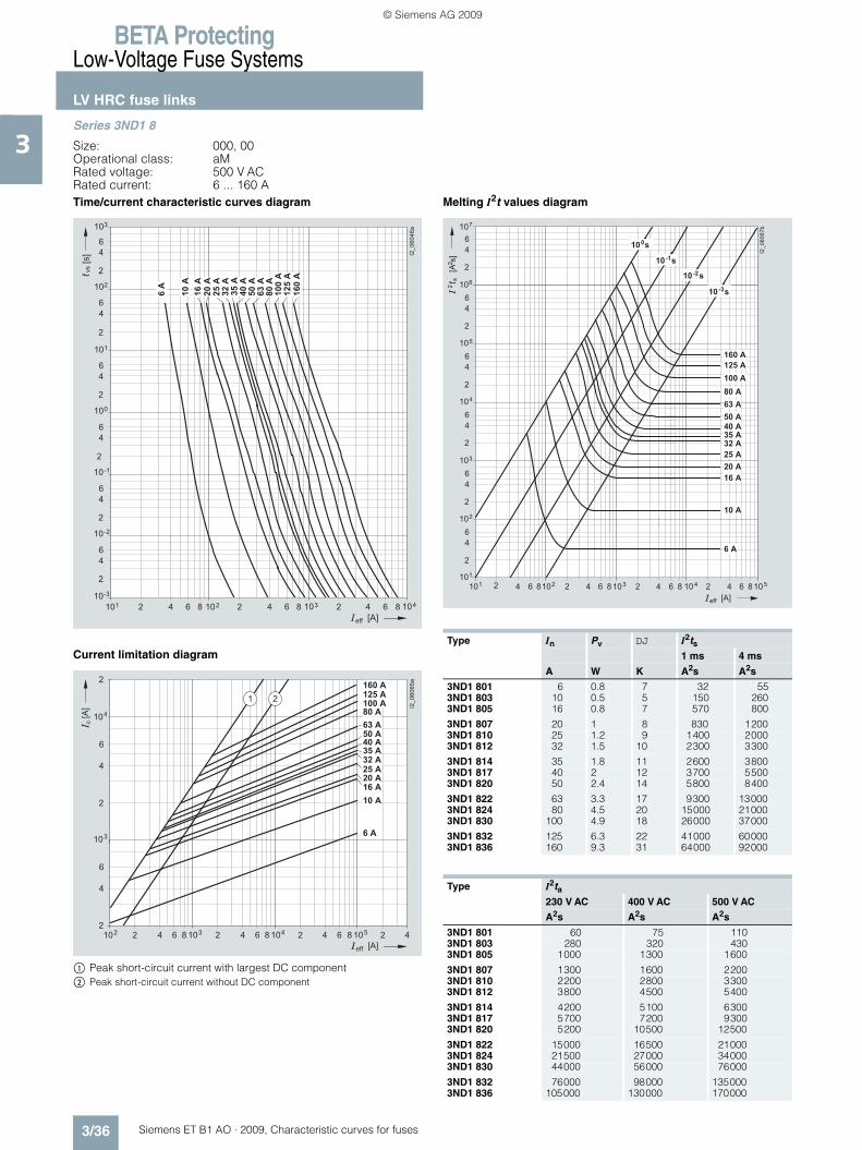
BETA ProtectingLow-Voltage Fuse Systems
LV HRC fuse links
3/36 Siemens ET B1 AO · 2009, Characteristic curves for fuses
3Series 3ND1 8
Size: 000, 00Operational class: aMRated voltage: 500 V ACRated current: 6 ... 160 ATime/current characteristic curves diagram
Current limitation diagram
$ Peak short-circuit current with largest DC component% Peak short-circuit current without DC component
Melting I2t values diagram
� �
� � �
�
�
�
� � �
�� � �� � �� � �� � �
�
�
�
� �
�
�
�
� �
�
�
�
�
�
�
�
� �
�
�
�
� �
��������
� � ��
���
����
���
����
�����
����
�����
���
����
���
���
����
����
��
��
� � � � � �
���
��
� �� ��
�
�
�
�
� � � � �
�
�
�
�
� � � �
� � �
� � � �
� � � �
� � � �
� � �
� �
� � �
� � � �
� � �
�
� � �� � �
���
��
�
�� �� ��
�� �� ��
�� �
� � � �
� � �
��������
� � � � �
�
Type In Pv DJ I2ts1 ms 4 ms
A W K A2s A2s
3ND1 801 6 0.8 7 32 553ND1 803 10 0.5 5 150 2603ND1 805 16 0.8 7 570 800
3ND1 807 20 1 8 830 12003ND1 810 25 1.2 9 1400 20003ND1 812 32 1.5 10 2300 3300
3ND1 814 35 1.8 11 2600 38003ND1 817 40 2 12 3700 55003ND1 820 50 2.4 14 5800 8400
3ND1 822 63 3.3 17 9300 130003ND1 824 80 4.5 20 15000 210003ND1 830 100 4.9 18 26000 37000
3ND1 832 125 6.3 22 41000 600003ND1 836 160 9.3 31 64000 92000
Type I2ta230 V AC 400 V AC 500 V AC
A2s A2s A2s
3ND1 801 60 75 1103ND1 803 280 320 4303ND1 805 1000 1300 1600
3ND1 807 1300 1600 22003ND1 810 2200 2800 33003ND1 812 3800 4500 5400
3ND1 814 4200 5100 63003ND1 817 5700 7200 93003ND1 820 5200 10500 12500
3ND1 822 15000 16500 210003ND1 824 21500 27000 340003ND1 830 44000 56000 76000
3ND1 832 76000 98000 1350003ND1 836 105000 130000 170000
� � � � � � �� � �� � �� � �� �� � � �� ��
�
�
�
�
�
�
�
�
�
�
�
�
�
�
�
�
�
�
�
�
�
�
�
�
�
������ �
�
�
�
�
�
� ���
� � ��
� � ��
� � �
� � � �
� � �
� � � �
� � � �
� � �
� � �
� �
� � � �
� � �
� � �
� � � �
� � � � �
� � � �
� � � � �
� � � � � �
��
�����
�
ET_B1_AO_Kennlinien.book Seite 36 Dienstag, 13. Oktober 2009 11:58 11
© Siemens AG 2009

BETA ProtectingLow-Voltage Fuse Systems
LV HRC fuse links
3/37Siemens ET B1 AO · 2009, Characteristic curves for fuses
3Series 3ND1 3.., 3ND2
Size: 1, 2, 3Operational class: aMRated voltage: 690 V ACRated current: 63 ... 630 ATime/current characteristic curves diagram
Current limitation diagram
$ Peak short-circuit current with largest DC component% Peak short-circuit current without DC component
Melting I2t values diagram
Table see page 3/38.
� � �
� � �
�
�
�
� � �
�� � �� � �� � �� � �
�
�
�
� �
�
�
�
� �
�
�
�
�
�
�
�
� �
�
�
�
� �
�������
� � ��
����
�����
����
�����
���
�����
����
���
��
�����
����
����
��
� � � � � �
���
��
� �� ��
�
�
�
�
�
�
� � �� � �
���
��
�� �� ��
�� �� ��
�
��������
�
��
� � � � �
� � � � �
� � � �
� � � �
� �
� � � � �
� � � �
� � � �
� � �
� � � �
� � � � �
� � �
�
� � � � �� � �� � �� � �� � �� �� � � �� ��
�
�
�
�
�
�
�
�
�
�
�
�
�
�
�
�
�
�
�
�
�
�
�
�
�
��������
�
�
�
�
�
�
� � �
� � � �
� � � � �
� � � �
� � � � �
� � � � �
� � � �
� �
� � � � �
� � � �
� � � �
� � � � � �
��
�����
�
� ���
� � ��
� � ��
� � �
� � ��
� � �
ET_B1_AO_Kennlinien.book Seite 37 Dienstag, 13. Oktober 2009 11:58 11
© Siemens AG 2009
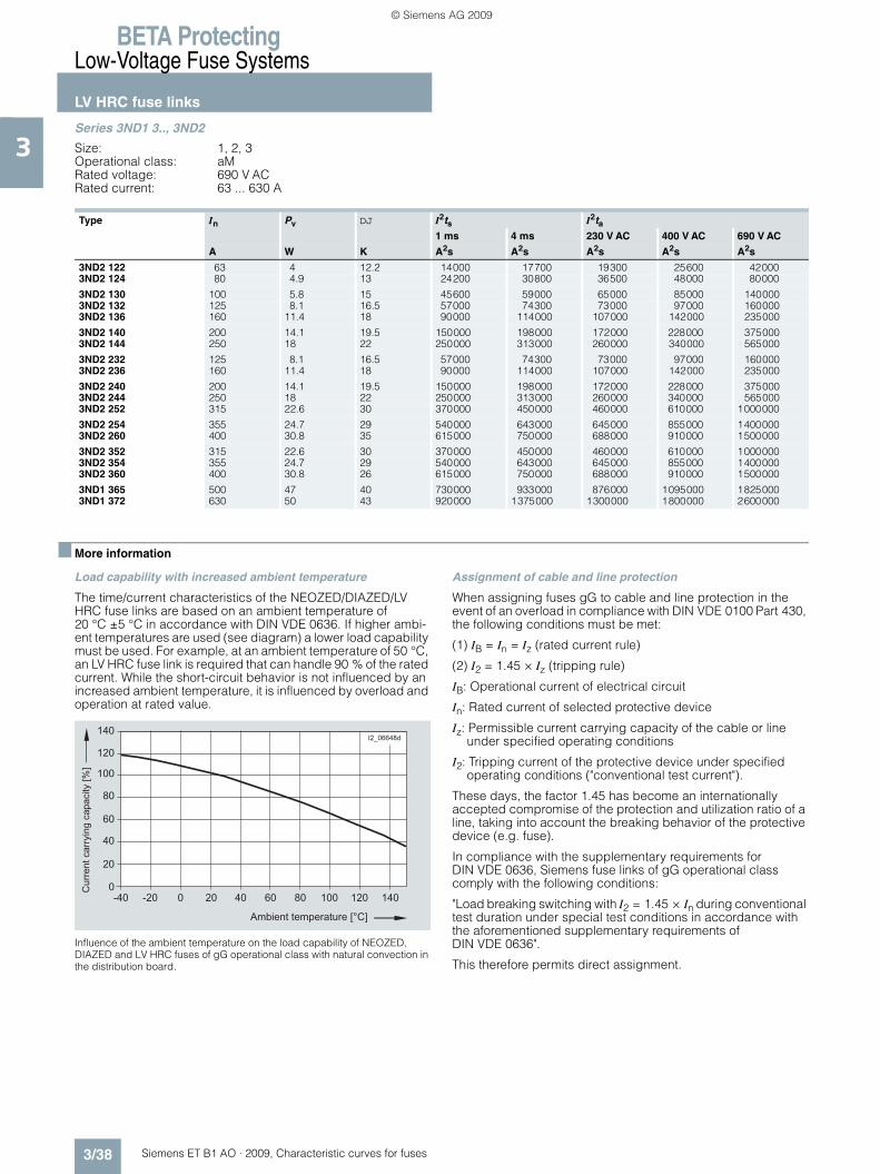
BETA ProtectingLow-Voltage Fuse Systems
LV HRC fuse links
3/38 Siemens ET B1 AO · 2009, Characteristic curves for fuses
3Series 3ND1 3.., 3ND2
Size: 1, 2, 3Operational class: aMRated voltage: 690 V ACRated current: 63 ... 630 A
■ More information
Load capability with increased ambient temperature
The time/current characteristics of the NEOZED/DIAZED/LV HRC fuse links are based on an ambient temperature of 20 °C ±5 °C in accordance with DIN VDE 0636. If higher ambi-ent temperatures are used (see diagram) a lower load capability must be used. For example, at an ambient temperature of 50 °C, an LV HRC fuse link is required that can handle 90 % of the rated current. While the short-circuit behavior is not influenced by an increased ambient temperature, it is influenced by overload and operation at rated value.
Influence of the ambient temperature on the load capability of NEOZED, DIAZED and LV HRC fuses of gG operational class with natural convection in the distribution board.
Assignment of cable and line protection
When assigning fuses gG to cable and line protection in the event of an overload in compliance with DIN VDE 0100 Part 430, the following conditions must be met:
(1) IB = In = Iz (rated current rule)
(2) I2 = 1.45 × Iz (tripping rule)
IB: Operational current of electrical circuit
In: Rated current of selected protective device
Iz: Permissible current carrying capacity of the cable or line under specified operating conditions
I2: Tripping current of the protective device under specified operating conditions ("conventional test current").
These days, the factor 1.45 has become an internationally accepted compromise of the protection and utilization ratio of a line, taking into account the breaking behavior of the protective device (e.g. fuse).
In compliance with the supplementary requirements for DIN VDE 0636, Siemens fuse links of gG operational class comply with the following conditions:
"Load breaking switching with I2 = 1.45 × In during conventional test duration under special test conditions in accordance with the aforementioned supplementary requirements of DIN VDE 0636".
This therefore permits direct assignment.
Type In Pv DJ I2ts I2ta1 ms 4 ms 230 V AC 400 V AC 690 V AC
A W K A2s A2s A2s A2s A2s
3ND2 122 63 4 12.2 14000 17700 19300 25600 420003ND2 124 80 4.9 13 24200 30800 36500 48000 80000
3ND2 130 100 5.8 15 45600 59000 65000 85000 1400003ND2 132 125 8.1 16.5 57000 74300 73000 97000 1600003ND2 136 160 11.4 18 90000 114000 107000 142000 235000
3ND2 140 200 14.1 19.5 150000 198000 172000 228000 3750003ND2 144 250 18 22 250000 313000 260000 340000 565000
3ND2 232 125 8.1 16.5 57000 74300 73000 97000 1600003ND2 236 160 11.4 18 90000 114000 107000 142000 235000
3ND2 240 200 14.1 19.5 150000 198000 172000 228000 3750003ND2 244 250 18 22 250000 313000 260000 340000 5650003ND2 252 315 22.6 30 370000 450000 460000 610000 1000000
3ND2 254 355 24.7 29 540000 643000 645000 855000 14000003ND2 260 400 30.8 35 615000 750000 688000 910000 1500000
3ND2 352 315 22.6 30 370000 450000 460000 610000 10000003ND2 354 355 24.7 29 540000 643000 645000 855000 14000003ND2 360 400 30.8 26 615000 750000 688000 910000 1500000
3ND1 365 500 47 40 730000 933000 876000 1095000 18250003ND1 372 630 50 43 920000 1375000 1300000 1800000 2600000
��� ��� ��
��
��
��
��
��
���
���
���
��
�� �� ��� ��� ���
�������
� �������� �������������
���
����
����
������
����
�������
�
ET_B1_AO_Kennlinien.book Seite 38 Dienstag, 13. Oktober 2009 11:58 11
© Siemens AG 2009

BETA ProtectingLow-Voltage Fuse Systems
Notes
3/39Siemens ET B1 AO · 2009, Characteristic curves for fuses
3
ET_B1_AO_Kennlinien.book Seite 39 Dienstag, 13. Oktober 2009 11:58 11
© Siemens AG 2009
BETA ProtectingLow-Voltage Fuse Systems
Notes
3/40 Siemens ET B1 AO · 2009, Characteristic curves for fuses
3
ET_B1_AO_Kennlinien.book Seite 40 Dienstag, 13. Oktober 2009 11:58 11
© Siemens AG 2009

Siemens ET B1 AO · 2009, Characteristic curves for fuses
44
BETA ProtectingSITOR Semiconductor Fuses
4/2 Application information
4/3 SITOR, LV HRC design
4/44 SITOR, cylindrical fuse design
4/53 SILIZED, NEOZED and DIAZED design
4/56 Configuration
ET_B1_AO_Kennlinien.book Seite 1 Dienstag, 13. Oktober 2009 11:58 11
© Siemens AG 2009

BETA ProtectingSITOR Semiconductor Fuses
Application information
4/2 Siemens ET B1 AO · 2009, Characteristic curves for fuses
4
■ Overview
Characteristics
SITOR fuse links protect converter equipment against short circuits.
The power semiconductors used in these devices (diodes, thyristors, GTOs and others) require high-speed elements for protection due to their low thermal capacity. SITOR fuse links (super quick fuse links for semiconductor protection) are ideal for this type of application.
The following types of short-circuit faults can occur:• Internal short circuit:
A faulty semiconductor device causes a short circuit within the power converter
• External short circuit: A fault in the load causes a short circuit on the output side of the power converter
• Shoot-throughs: In the event of a failure of the chassis converter control system during inverter operation (commutation failure), the converter connection forms a short-circuit type connection between the DC and AC power supply system.
Fuse links can be arranged in a number of ways within the con-verter connection. A distinction is made between phase fuses in three-phase current incoming feeders and, if applicable, DC fuses and arm fuses in the arms of the converter connections (see adjacent graphs). In the case of center tap connections, fuse links can only be arranged as phase fuses in three-phase current incoming feeders.
When using SITOR fuse links of operational class aR, the over-load protection of converter equipment, up to approx. 3.5 times the rated current of the fuse link, is taken from conventional pro-tective devices (for example, thermal-delayed overload relays) or, in the case of controlled power converters, from the current limiter (exception: full range fuses).
As semiconductor protection, SITOR fuse links of the 3NE1 ...-0 series with gS operational class are also suitable for the overload and short-circuit protection of cables, lines and busbars. All other dual-function fuses of the SITOR series have a gR charac-teristic. Overload protection is ensured as long as the rated cur-rent of the SITOR fuse links of the series 3NE1 ...-0 is selected as In £Iz (DIN VDE 0100 Part 430).
The rules of DIN VDE 0100 Part 430 must be applied when rating short-circuit protection for cables, lines and busbars.
Configuration options
I2_
10
89
8
Three-phase bidirectional connection W3 with pase fuses with arm fuses
I2_
10
89
3
I2_
10
89
4
( ) ( )
Six-pulse bridge circuit B6 with phase fuses
Six-pulse bridge circuit B6 with phase fuses and DC fuse (reversible connection)
I2_
10
89
5
I2_
10
89
6
Six-pulse bridge circuit B6 with phase fuses and DC fuse (switching for converter)
Six-pulse bridge circuit B6 with arm fuses
I2_
10
89
7
( ) ( )
Six-pulse bridge circuit B6 with arm fuses (reversible connection)
ET_B1_AO_Kennlinien.book Seite 2 Dienstag, 13. Oktober 2009 11:58 11
© Siemens AG 2009
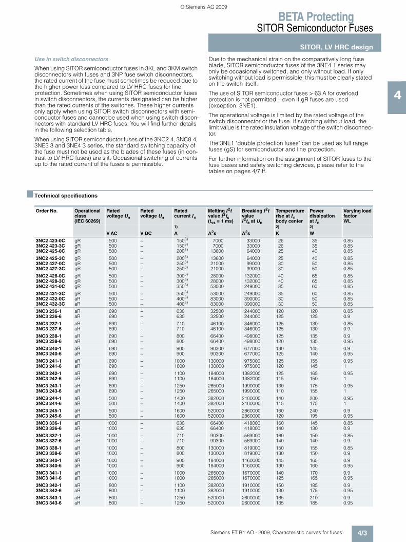
BETA ProtectingSITOR Semiconductor Fuses
SITOR, LV HRC design
4/3Siemens ET B1 AO · 2009, Characteristic curves for fuses
4
Use in switch disconnectors
When using SITOR semiconductor fuses in 3KL and 3KM switch disconnectors with fuses and 3NP fuse switch disconnectors, the rated current of the fuse must sometimes be reduced due to the higher power loss compared to LV HRC fuses for line protection. Sometimes when using SITOR semiconductor fuses in switch disconnectors, the currents designated can be higher than the rated currents of the switches. These higher currents only apply when using SITOR switch disconnectors with semi-conductor fuses and cannot be used when using switch discon-nectors with standard LV HRC fuses. You will find further details in the following selection table.
When using SITOR semiconductor fuses of the 3NC2 4, 3NC8 4, 3NE3 3 and 3NE4 3 series, the standard switching capacity of the fuse must not be used as the blades of these fuses (in con-trast to LV HRC fuses) are slit. Occasional switching of currents up to the rated current of the fuses is permissible.
Due to the mechanical strain on the comparatively long fuse blade, SITOR semiconductor fuses of the 3NE4 1 series may only be occasionally switched, and only without load. If only switching without load is permissible, this must be clearly stated on the switch itself.
The use of SITOR semiconductor fuses > 63 A for overload protection is not permitted – even if gR fuses are used (exception: 3NE1).
The operational voltage is limited by the rated voltage of the switch disconnector or the fuse. If switching without load, the limit value is the rated insulation voltage of the switch disconnec-tor.
The 3NE1 "double protection fuses" can be used as full range fuses (gS) for semiconductor and line protection.
For further information on the assignment of SITOR fuses to the fuse bases and safety switching devices, please refer to the tables on pages 4/7 ff.
■ Technical specifications
Order No. Operational class(IEC 60269)
Rated voltage Un
Rated voltage Un
Rated current In
Melting I2t value I2ts (tvs = 1 ms)
Breaking I2t value I2ta at Un
Temperature rise at In body center
Power dissipation at In
Varying load factorWL
V AC V DC1)
A A2s A2s2)
K2)
W
3NC2 423-0C gR 500 -- 1503) 7000 33000 26 35 0.853NC2 423-3C gR 500 -- 1503) 7000 33000 26 35 0.853NC2 425-0C gR 500 -- 2003) 13600 64000 25 40 0.85
3NC2 425-3C gR 500 -- 2003) 13600 64000 25 40 0.853NC2 427-0C gR 500 -- 2503) 21000 99000 30 50 0.853NC2 427-3C gR 500 -- 2503) 21000 99000 30 50 0.85
3NC2 428-0C gR 500 -- 3003) 28000 132000 40 65 0.853NC2 428-3C gR 500 -- 3003) 28000 132000 40 65 0.853NC2 431-0C gR 500 -- 3503) 53000 249000 35 60 0.85
3NC2 431-3C gR 500 -- 3503) 53000 249000 35 60 0.853NC2 432-0C aR 500 -- 4003) 83000 390000 30 50 0.853NC2 432-3C aR 500 -- 4003) 83000 390000 30 50 0.85
3NC3 236-1 aR 690 -- 630 32500 244000 120 120 0.853NC3 236-6 aR 690 -- 630 32500 244000 125 125 0.9
3NC3 237-1 aR 690 -- 710 46100 346000 125 130 0.853NC3 237-6 aR 690 -- 710 46100 346000 125 130 0.9
3NC3 238-1 aR 690 -- 800 66400 498000 125 135 0.93NC3 238-6 aR 690 -- 800 66400 498000 120 135 0.95
3NC3 240-1 aR 690 -- 900 90300 677000 130 145 0.93NC3 240-6 aR 690 -- 900 90300 677000 125 140 0.95
3NC3 241-1 aR 690 -- 1000 130000 975000 125 155 0.953NC3 241-6 aR 690 -- 1000 130000 975000 120 145 1
3NC3 242-1 aR 690 -- 1100 184000 1382000 125 165 0.953NC3 242-6 aR 690 -- 1100 184000 1382000 115 150 1
3NC3 243-1 aR 690 -- 1250 265000 1990000 130 175 0.953NC3 243-6 aR 690 -- 1250 265000 1990000 110 155 1
3NC3 244-1 aR 500 -- 1400 382000 2100000 140 200 0.953NC3 244-6 aR 500 -- 1400 382000 2100000 115 175 1
3NC3 245-1 aR 500 -- 1600 520000 2860000 160 240 0.93NC3 245-6 aR 500 -- 1600 520000 2860000 120 195 0.95
3NC3 336-1 aR 1000 -- 630 66400 418000 160 145 0.853NC3 336-6 aR 1000 -- 630 66400 418000 140 130 0.9
3NC3 337-1 aR 1000 -- 710 90300 569000 160 150 0.853NC3 337-6 aR 1000 -- 710 90300 569000 140 140 0.9
3NC3 338-1 aR 1000 -- 800 130000 819000 150 155 0.853NC3 338-6 aR 1000 -- 800 130000 819000 130 150 0.9
3NC3 340-1 aR 1000 -- 900 184000 1160000 145 165 0.93NC3 340-6 aR 1000 -- 900 184000 1160000 130 160 0.95
3NC3 341-1 aR 1000 -- 1000 265000 1670000 140 170 0.93NC3 341-6 aR 1000 -- 1000 265000 1670000 125 165 0.95
3NC3 342-1 aR 800 -- 1100 382000 1910000 150 185 0.93NC3 342-6 aR 800 -- 1100 382000 1910000 130 175 0.95
3NC3 343-1 aR 800 -- 1250 520000 2600000 165 210 0.93NC3 343-6 aR 800 -- 1250 520000 2600000 135 185 0.95
ET_B1_AO_Kennlinien.book Seite 3 Dienstag, 13. Oktober 2009 11:58 11
© Siemens AG 2009

BETA ProtectingSITOR Semiconductor Fuses
SITOR, LV HRC design
4/4 Siemens ET B1 AO · 2009, Characteristic curves for fuses
4 3NC3 430-1 aR 1250 -- 315 10600 72500 60 80 0.953NC3 430-6 aR 1250 -- 315 10600 72500 60 80 0.95
3NC3 432-1 aR 1250 -- 400 23900 163000 95 95 0.953NC3 432-6 aR 1250 -- 400 23900 163000 95 95 0.95
3NC3 434-1 aR 1250 -- 500 42500 290000 115 115 0.93NC3 434-6 aR 1250 -- 500 42500 290000 115 115 0.9
3NC3 436-1 aR 1250 -- 630 96600 650000 120 120 0.953NC3 436-6 aR 1250 -- 630 96600 650000 120 120 0.95
3NC3 438-1 aR 1100 -- 800 170000 985000 145 145 0.93NC3 438-6 aR 1100 -- 800 170000 985000 145 145 0.9
3NC5 5314) aR 800 -- 3505) 66000 260000 200 80 0.93NC5 8384) aR 1000 -- 8005) 360000 1728000 130 170 0.9
3NC5 8404) aR 1000 -- 6005) 185000 888000 110 150 0.93NC5 8414) aR 800 -- 6305) 185000 888000 110 145 0.9
3NC7 327-2 aR 680 -- 250 244000 635000 45 25 0.93NC7 331-2 aR 680 -- 350 550000 1430000 66 32 0.9
3NC8 423-0C gR 690 -- 1503) 1100 17600 33 40 0.853NC8 423-3C gR 690 -- 1503) 1100 17600 33 40 0.85
3NC8 425-0C gR 690 -- 2003) 2400 38400 46 55 0.853NC8 425-3C gR 690 -- 2003) 2400 38400 46 55 0.85
3NC8 427-0C gR 690 -- 2503) 4400 70400 95 72 0.853NC8 427-3C gR 690 -- 2503) 4400 70400 95 72 0.85
3NC8 431-0C gR 690 -- 3503) 11000 176000 65 95 0.853NC8 431-3C gR 690 -- 3503) 11000 176000 65 95 0.85
3NC8 434-0C gR 690 -- 5003) 28000 448000 75 130 0.853NC8 434-3C gR 690 -- 5003) 28000 448000 75 130 0.85
3NC8 444-3C aR 600 -- 1000 400000 2480000 110 140 0.9
3NE1 020-2 gR 690 -- 80 780 5800 45 10.5 13NE1 021-0 gS 690 -- 100 3100 33000 36 10 13NE1 021-2 gR 690 -- 100 1490 11000 49 11.5 1
3NE1 022-0 gS 690 -- 125 6000 63000 40 11 13NE1 022-2 gR 690 -- 125 3115 23000 55 13.5 1
3NE1 224-0 gS 690 -- 160 7400 60000 60 24 13NE1 224-2 gR 690 -- 160 2650 18600 70 30 13NE1 224-3 gR 690 -- 160 2650 18600 70 30 1
3NE1 225-0 gS 690 -- 200 14500 100000 65 27 13NE1 225-2 gR 690 -- 200 5645 51800 62 28 13NE1 225-3 gR 690 -- 200 5645 51800 62 28 1
3NE1 227-0 gS 690 -- 250 29500 200000 75 30 13NE1 227-2 gR 690 -- 250 11520 80900 70 35 13NE1 227-3 gR 690 -- 250 11520 80900 70 35 1
3NE1 230-0 gS 690 -- 315 46100 310000 80 38 13NE1 230-2 gR 690 -- 315 22580 168000 75 42 13NE1 230-3 gR 690 -- 315 22580 168000 75 42 1
3NE1 331-0 gS 690 -- 350 58000 430000 75 42 13NE1 331-2 gR 690 -- 350 29500 177000 82 44 13NE1 331-3 gR 690 -- 350 29500 177000 82 44 1
3NE1 332-0 gS 690 -- 400 84000 590000 85 45 13NE1 332-2 gR 690 -- 400 37300 177000 100 54 13NE1 332-3 gR 690 -- 400 37300 177000 100 54 1
3NE1 333-0 gS 690 -- 450 104000 750000 85 53 13NE1 333-2 gR 690 -- 450 46100 276500 100 62 13NE1 333-3 gR 690 -- 450 46100 276500 100 62 1
3NE1 334-0 gS 690 -- 500 149000 950000 90 56 13NE1 334-2 gR 690 -- 500 66400 398000 100 65 13NE1 334-3 gR 690 -- 500 66400 398000 100 65 1
3NE1 435-0 gS 690 -- 560 215000 1700000 65 50 13NE1 435-2 gR 690 -- 560 130000 890000 80 60 13NE1 436-3 gR 690 -- 560 130000 890000 80 60 1
3NE1 436-0 gS 690 -- 630 293000 2350000 70 55 13NE1 436-2 gR 690 -- 630 203000 1390000 82 62 13NE1 436-3 gR 690 -- 630 203000 1390000 82 62 1
3NE1 437-0 gS 690 -- 710 437000 3400000 68 60 13NE1 437-1 gR 600 -- 710 321000 2460000 85 65 13NE1 437-2 gR 690 -- 710 265000 1818000 90 72 13NE1 437-3 gR 690 -- 710 265000 1818000 90 72 1
Order No. Operational class(IEC 60269)
Rated voltage Un
Rated voltage Un
Rated current In
Melting I2t value I2ts (tvs = 1 ms)
Breaking I2t value I2ta at Un
Temperature rise at In body center
Power dissipation at In
Varying load factorWL
V AC V DC1)
A A2s A2s2)
K2)
W
ET_B1_AO_Kennlinien.book Seite 4 Dienstag, 13. Oktober 2009 11:58 11
© Siemens AG 2009

BETA ProtectingSITOR Semiconductor Fuses
SITOR, LV HRC design
4/5Siemens ET B1 AO · 2009, Characteristic curves for fuses
43NE1 438-0 gS 690 -- 800 723000 5000000 70 59 13NE1 438-1 gR 600 -- 800 437000 3350000 95 72 13NE1 438-2 gR 690 -- 800 361000 2475000 95 82 13NE1 438-3 gR 690 -- 800 361000 2475000 95 82 1
3NE1 447-2 gR 690 -- 670 240000 1640000 90 65 13NE1 447-3 gR 690 -- 670 240000 1640000 90 65 1
3NE1 448-2 gR 690 -- 850 520000 3640000 95 76 13NE1 448-3 gR 690 -- 850 520000 3640000 95 76 1
3NE1 802-0 gS 690 -- 40 295 3000 30 5 13NE1 803-0 gS 690 -- 35 166 1700 35 5 13NE1 813-0 gS 690 -- 16 18 200 25 3 1
3NE1 814-0 gS 690 - 20 41 430 25 3.5 13NE1 815-0 gS 690 -- 25 74 780 30 4 13NE1 817-0 gS 690 -- 50 461 4400 35 6 1
3NE1 818-0 gS 690 -- 63 903 9000 40 7 13NE1 820-0 gS 690 -- 80 1843 18000 40 8 1
3NE3 221 aR 1000 -- 100 665 4800 65 28 0.953NE3 222 aR 1000 -- 125 1040 7200 70 36 0.953NE3 224 aR 1000 -- 160 1850 13000 90 42 1
3NE3 225 aR 1000 -- 200 4150 30000 80 42 13NE3 227 aR 1000 -- 250 6650 48000 90 50 13NE3 230-0B aR 1000 -- 315 13400 80000 100 65 0.95
3NE3 231 aR 1000 -- 350 16600 100000 120 75 0.93NE3 232-0B aR 1000 -- 400 22600 135000 140 85 0.93NE3 233 aR 1000 -- 450 29500 175000 130 95 0.9
3NE3 332-0B aR 1000 -- 400 22600 135000 120 85 13NE3 333 aR 1000 -- 450 29500 175000 125 90 13NE3 334-0B aR 1000 -- 500 46100 260000 115 90 1
3NE3 335 aR 1000 -- 560 66500 360000 120 95 13NE3 336 aR 1000 --- 630 104000 600000 110 100 13NE3 337-8 aR 900 -- 710 149000 800000 125 110 1
3NE3 338-8 aR 800 -- 800 184000 850000 140 130 0.953NE3 340-8 aR 690 -- 900 223000 920000 160 165 0.95
3NE3 421-0C aR 1000 -- 100 1800 13500 45 25 13NE3 430-0C aR 1000 -- 315 29000 218000 120 80 13NE3 432-0C aR 1000 -- 400 48500 364000 130 110 1
3NE3 434-0C aR 1000 -- 500 116000 870000 120 95 13NE3 525-56) aR 1000 -- 2007) 7150 44000 75 50 0.853NE3 535-56) aR 1000 -- 4507) 64500 395000 130 90 0.85
3NE3 626-0C aR 1000 -- 224 7200 54000 140 85 13NE3 635-0C aR 1000 -- 450 65000 488000 150 110 13NE3 635-6 aR 1000 -- 450 65000 488000 150 110 1
3NE3 636-0C aR 1000 -- 630 170000 1280000 136 132 13NE3 637-0C aR 1000 -- 710 260000 1950000 170 145 13NE3 637-1C8) aR 1000 -- 710 260000 1950000 170 145 1
3NE4 101 gR 1000 -- 32 40 280 45 12 0.93NE4 102 gR 1000 -- 40 75 500 50 13 0.93NE4 117 gR 1000 -- 50 120 800 65 16 0.9
3NE4 117-5 gR 1000 -- 50 135 1100 95 20 0.853NE4 118 aR 1000 -- 63 230 1500 78 20 0.93NE4 120 aR 1000 -- 80 450 3000 82 22 0.9
3NE4 121 aR 1000 -- 100 900 6000 85 24 0.93NE4 121-5 aR 1000 -- 100 900 7400 135 35 0.853NE4 122 aR 1000 -- 125 1800 14000 100 30 0.9
3NE4 124 aR 1000 -- 160 3600 29000 120 35 0.93NE4 146-5 aR 800 -- 170 7370 60500 142 43 0.85
3NE4 327-0B aR 800 -- 250 3600 29700 175 105 0.853NE4 327-6B6) aR 800 -- 250 3600 29700 175 105 0.853NE4 330-0B aR 800 -- 315 7400 60700 170 120 0.85
3NE4 330-6B6) aR 800 -- 315 7400 60700 170 120 0.853NE4 333-0B aR 800 -- 450 29400 191000 190 140 0.853NE4 333-6B6) aR 800 -- 450 29400 191000 190 140 0.85
3NE4 334-0B aR 800 -- 500 42500 276000 195 155 0.853NE4 334-6B6) aR 800 -- 500 42500 276000 195 155 0.853NE4 337 aR 800 -- 710 142000 923000 170 155 0.95
3NE4 337-66) aR 800 -- 710 142000 923000 170 155 0.95
Order No. Operational class(IEC 60269)
Rated voltage Un
Rated voltage Un
Rated current In
Melting I2t value I2ts (tvs = 1 ms)
Breaking I2t value I2ta at Un
Temperature rise at In body center
Power dissipation at In
Varying load factorWL
V AC V DC1)
A A2s A2s2)
K2)
W
ET_B1_AO_Kennlinien.book Seite 5 Dienstag, 13. Oktober 2009 11:58 11
© Siemens AG 2009

BETA ProtectingSITOR Semiconductor Fuses
SITOR, LV HRC design
4/6 Siemens ET B1 AO · 2009, Characteristic curves for fuses
4 3NE5 424-0C aR 1500 -- 160 7200 54000 75 56 13NE5 426-0C aR 1500 -- 224 18400 138000 100 80 13NE5 430-0C aR 1500 -- 315 41500 311000 125 115 1
3NE5 431-0C aR 1500 -- 350 57000 428000 150 135 13NE5 433-0C aR 1500 -- 450 116000 870000 150 145 0.953NE5 433-1C aR 1500 -- 450 116000 870000 150 145 0.95
3NE5 627-0C aR 1500 -- 250 11200 84000 170 130 13NE5 633-0C aR 1500 -- 450 78500 590000 170 160 13NE5 643-0C aR 1500 -- 600 260000 1950000 160 145 1
3NE6 437 aR 900 -- 7109) 100000 620000 80 150 0.93NE6 437-7 aR 900 -- 71010) 100000 620000 110 150 0.93NE6 444 aR 900 -- 9009) 400000 1920000 80 170 0.9
3NE7 425-0C aR 2000 -- 200 18400 138000 85 75 13NE7 427-0C aR 2000 -- 250 29000 218000 110 110 13NE7 431-0C aR 2000 -- 350 74000 555000 105 120 1
3NE7 432-0C aR 2000 -- 400 116000 870000 130 150 13NE7 633-0C aR 2000 -- 450 128000 960000 165 160 13NE7 633-1C11) aR 2000 -- 450 128000 960000 165 160 1
3NE7 636-0C aR 2000 -- 630 260000 1950000 200 220 13NE7 636-1C11) aR 2000 -- 630 260000 1950000 200 220 13NE7 637-1C11) aR 2000 -- 710 415000 3110000 230 275 1
3NE7 648-1C11) aR 2000 -- 525 149000 1120000 210 210 1
3NE8 003-1 gR 690 -- 35 70 400 45 9 0.953NE8 015-1 gR 690 -- 25 30 180 35 7 0.953NE8 017-1 gR 690 -- 50 120 700 65 14 0.95
3NE8 018-1 gR 690 -- 63 260 1400 70 16 0.953NE8 020-1 aR 690 -- 80 450 2400 80 19 0.953NE8 021-1 aR 690 -- 100 850 4200 90 22 0.95
3NE8 022-1 aR 690 -- 125 1400 6500 110 28 0.953NE8 024-1 aR 690 -- 160 2800 13000 130 38 0.95
3NE8 701-1 gR 690 70012) 32 40 285 45 10 0.93NE8 702-1 gR 690 70012) 40 69 490 55 12 0.93NE8 714-1 gR 690 70012) 20 12 83 40 7 0.9
3NE8 715-1 gR 690 70012) 25 19 140 40 9 0.93NE8 717-1 gR 690 70012) 50 115 815 60 15 0.93NE8 718-1 aR 690 70012) 63 215 1550 70 16 0.95
3NE8 720-1 aR 690 70012) 80 380 2700 80 18 0.93NE8 721-1 aR 690 70012) 100 695 4950 75 19 0.953NE8 722-1 aR 690 70012) 125 1250 9100 80 23 0.95
3NE8 724-1 aR 690 70012) 160 2350 17000 100 31 0.93NE8 725-1 aR 690 70012) 200 4200 30000 120 36 0.93NE8 727-1 aR 690 70012) 250 7750 55000 125 42 0.9
3NE8 731-1 aR 690 70012) 315 12000 85500 150 54 0.85
3NE9 440-6 gR 600 -- 850 400000 2480000 74 85 13NE9 450 aR 600 -- 12509) 400000 2480000 80 210 0.93NE9 450-7 aR 600 -- 125010) 400000 2480000 105 210 0.9
3NE9 632-1C aR 2500 -- 400 81000 620000 160 205 13NE9 634-1C aR 2500 -- 500 170000 1270000 180 235 13NE9 636-1C aR 2500 -- 630 385000 2800000 198 275 1
1) Maximum tightening torque: M10 capped thread: 35 Nm, depth of screw entry ‡ 9 mm.
2) Temperature rise and power dissipation for operation in LV HRC fuse base.
3) Cooling air speed 1 m/s. In the case of natural air cooling, reduction of 5 %.
4) Maximum tightening torque: - M10 thread (with indicator): 40 Nm- M10 capped thread: 50 Nm, depth of screw entry ‡ 9 mm- M24 × 1.5 thread: 60 Nm.
5) Temperature of water-cooled busbar max. +45 °C.
6) Maximum tightening torque: M10 capped thread: 35 Nm, depth of screw entry ‡ 9 mm.
7) Cooling air speed ‡ 0.5 m/s. In the case of natural air cooling, reduction of 5 %.
8) Gauge 140 mm, M12 screw connection.
9) Cooling air speed ‡ 2 m/s.
10) Bottom (cooled) connection max. +60 °C, top connection (M10) max. +110 °C.
11) M12 screw connection.
12) Rated voltage acc. to UL.
Order No. Operational class(IEC 60269)
Rated voltage Un
Rated voltage Un
Rated current In
Melting I2t value I2ts (tvs = 1 ms)
Breaking I2t value I2ta at Un
Temperature rise at In body center
Power dissipation at In
Varying load factorWL
V AC V DC1)
A A2s A2s2)
K2)
W
ET_B1_AO_Kennlinien.book Seite 6 Dienstag, 13. Oktober 2009 11:58 11
© Siemens AG 2009

BETA ProtectingSITOR Semiconductor Fuses
SITOR, LV HRC design
4/7Siemens ET B1 AO · 2009, Characteristic curves for fuses
4
Load rating of SITOR fuse links with LV HRC 3NH fuse bases
SITOR fuse links Ømin Cu LV HRC fuse bases
Order No. Un Operational class
BG In WL Order No. BG Imax IWL
V AC A mm2 A A
3NC2 423-3C 500 gR. 3 150 0.95 70 3NH3 420/3NH3 430 3 150 1433NC2 425-3C 500 gR 3 200 0.95 95 3 190 1813NC2 427-3C 500 gR 3 250 0.95 120 3 240 228
3NC2 428-3C 500 gR 3 300 0.95 185 3 285 2713NC2 431-3C 500 gR 3 350 0.95 240 3 330 3143NC2 432-3C 500 aR 3 400 0.95 240 3 400 380
3NC3 336-1 1000 aR 3 630 0.85 480 3NH3 420/3NH3 430 3 560 4763NC3 337-1 1000 aR 3 710 0.85 560 3 600 5103NC3 338-1 1000 aR 3 800 0.85 640 3 640 544
3NC3 340-1 1000 aR 3 900 0.90 720 3 720 6483NC3 341-1 1000 aR 3 1000 0.90 800 3 800 7203NC3 342-1 800 aR 3 1100 0.90 880 3 880 792
3NC3 343-1 800 aR 3 1250 0.90 960 3 950 855
3NC8 423-3C 690 gR 3 150 0.85 70 3NH3 420/3NH3 430 3 135 1153NC8 425-3C 690 gR 3 200 0.85 95 3 180 1533NC8 427-3C 690 gR 3 250 0.85 120 3 250 213
3NC8 431-3C 690 gR 3 350 0.85 240 3 315 2683NC8 434-3C 690 gR 3 500 0.85 2 × 150 3 450 3833NC8 444-3C 600 aR 3 1000 0.95 2 × (60 × 6) 3 800 800
3NE1 020-2 690 gR 00 80 1.0 25 3NH3 030/3NH4 030 00 80 803NE1 021-0 690 gS 00 100 1.0 35 00 100 1003NE1 021-2 690 gR 00 100 1.0 35 00 100 100
3NE1 022-0 690 gS 00 125 1.0 50 00 125 1253NE1 022-2 690 gR 00 125 1.0 50 00 125 125
3NE1 224-0 690 gS 1 160 1.0 70 3NH3 230/3NH4 230 1 160 1603NE1 224-2 690 gR 1 160 1.0 70 1 160 1603NE1 224-3 690 gR 1 160 1.0 70 1 160 160
3NE1 225-0 690 gS 1 200 1.0 95 1 200 2003NE1 225-2 690 gR 1 200 1.0 95 1 200 2003NE1 225-3 690 gR 1 200 1.0 95 1 200 200
3NE1 227-0 690 gS 1 250 1.0 120 1 250 2503NE1 227-2 690 gR 1 250 1.0 120 1 250 2503NE1 227-3 690 gR 1 250 1.0 120 1 250 250
3NE1 230-0 690 gS 1 315 1.0 2 × 70 3NH3 320/3NH3 330 2 315 3153NE1 230-2 690 gR 1 315 1.0 2 × 70 2 315 3153NE1 230-3 690 gR 1 315 1.0 2 × 70 2 315 315
3NE1 331-0 690 gS 2 350 1.0 2 × 95 3NH3 320/3NH3 330 2 350 3503NE1 331-2 690 gR 2 350 1.0 2 × 95 2 350 3503NE1 331-3 690 gR 2 350 1.0 2 × 95 2 350 350
3NE1 332-0 690 gS 2 400 1.0 2 × 95 2 400 4003NE1 332-2 690 gR 2 400 1.0 2 × 95 2 400 4003NE1 332-3 690 gR 2 400 1.0 2 × 95 2 400 400
3NE1 333-0 690 gS 2 450 1.0 2 × 120 3NH3 420/3NH3 430 3 450 4503NE1 333-2 690 gR 2 450 1.0 2 × 120 3 450 4503NE1 333-3 690 gR 2 450 1.0 2 × 120 3 450 450
3NE1 334-0 690 gS 2 500 1.0 2 × 120 3 500 5003NE1 334-2 690 gR 2 500 1.0 2 × 120 3 500 5003NE1 334-3 690 gR 2 500 1.0 2 × 120 3 500 500
3NE1 435-0 690 gS 3 560 1.0 2 × 150 3NH3 420/3NH3 430 3 560 5603NE1 435-2 690 gR 3 560 1.0 2 × 150 3 560 5603NE1 435-3 690 gR 3 560 1.0 2 × 150 3 560 560
3NE1 436-0 690 gS 3 630 1.0 2 × 185 3 630 6303NE1 436-2 690 gR 3 630 1.0 2 × 185 3 630 6303NE1 436-3 690 gR 3 630 1.0 2 × 185 3 630 630
3NE1 437-0 690 gS 3 710 1.0 2 × (40 × 5) 3 710 7103NE1 437-1 600 gR 3 710 1.0 2 × (40 × 5) 3 690 6903NE1 437-2 690 gR 3 710 1.0 2 × (40 × 5) 3 710 7103NE1 437-3 690 gR 3 710 1.0 2 × (40 × 5) 3 710 710
3NE1 438-0 690 gS 3 800 1.0 2 × (50 × 5) 3 800 8003NE1 438-1 600 gR 3 800 1.0 2 × (50 × 5) 3 750 7503NE1 438-2 690 gR 3 800 1.0 2 × (50 × 5) 3 800 8003NE1 438-3 690 gR 3 800 1.0 2 × (50 × 5) 3 800 800
3NE1 447-2 690 gR 3 670 1.0 2 × (40 × 5) 3 670 6703NE1 447-3 690 gR 3 670 1.0 2 × (40 × 5) 3 670 670
3NE1 448-2 690 gR 3 850 1.0 2 × (40 × 8) 3 850 8503NE1 448-3 690 gR 3 850 1.0 2 × (40 × 8) 3 850 850
ET_B1_AO_Kennlinien.book Seite 7 Dienstag, 13. Oktober 2009 11:58 11
© Siemens AG 2009

BETA ProtectingSITOR Semiconductor Fuses
SITOR, LV HRC design
4/8 Siemens ET B1 AO · 2009, Characteristic curves for fuses
4
Un = Rated voltage
BG = Size
In = Rated current
WL = Varying load factor
Ømin Cu= Required conductor cross-section Cu
Imax = Maximum permissible current
IWL = Maximum permissible current with varying load.
3NE1 813-0 690 gS 000 16 1.0 1.5 3NH3 030/3NH4 030 00 16 163NE1 814-0 690 gS 000 20 1.0 2.5 00 20 203NE1 815-0 690 gS 000 25 1.0 4 00 25 25
3NE1 803-0 690 gS 000 35 1.0 6 00 35 353NE1 802-0 690 gS 000 40 1.0 10 00 40 403NE1 817-0 690 gS 000 50 1.0 10 00 50 50
3NE1 818-0 690 gS 000 63 1.0 16 00 63 633NE1 820-0 690 gS 000 80 1.0 25 00 80 80
3NE3 221 1000 aR 1 100 0.95 35 3NH3 230/3NH4 230 1 100 953NE3 222 1000 aR 1 125 0.95 50 1 125 1193NE3 224 1000 aR 1 160 1.0 70 1 160 160
3NE3 225 1000 aR 1 200 1.0 95 1 200 2003NE3 227 1000 aR 1 250 1.0 120 1 250 250
3NE3 230-0B 1000 aR 1 315 0.95 185 3NH3 320/3NH3 330 2 305 2903NE3 231 1000 aR 1 350 0.95 240 2 335 318
3NE3 232-0B 1000 aR 1 400 0.90 240 2 380 3423NE3 233 1000 aR 1 450 0.90 2 × 150 2 425 383
3NE3 332-0B 1000 aR 2 400 1.0 240 3NH3 420/3NH3 430 3 400 4003NE3 333 1000 aR 2 450 1.0 2 × 150 3 450 4503NE3 334-0B 1000 aR 2 500 1.0 2 × 150 3 500 500
3NE3 335 1000 aR 2 560 1.0 2 × 185 3 560 5603NE3 336 1000 aR 2 630 1.0 2 × 185 3 630 6303NE3 337-8 900 aR 2 710 1.0 2 × 200 3 680 680
3NE3 338-8 800 aR 2 800 0.95 2 × 200 3 700 6653NE3 340-8 690 aR 2 900 0.95 2 × 240 3 750 713
3NE4 101 1000 gR 0 32 0.9 6 3NH3 120/3NH4 230 0/1 32 293NE4 102 1000 gR 0 40 0.9 10 0/1 40 363NE4 117 1000 gR 0 50 0.9 10 0/1 50 45
3NE4 118 1000 aR 0 63 0.9 16 0/1 63 573NE4 120 1000 aR 0 80 0.9 25 0/1 80 723NE4 121 1000 aR 0 100 0.9 35 0/1 100 93
3NE4 122 1000 aR 0 125 0.9 50 0/1 125 1133NE4 124 1000 aR 0 160 0.9 70 0/1 160 144
3NE4 327-0B 800 aR 2 250 0.85 120 3NH3 320/3NH3 330 2 240 2043NE4 330-0B 800 aR 2 315 0.85 240 2 300 255
3NE4 333-0B 800 aR 2 450 0.85 2 × (30 × 5) 3NH3 420/3NH3 430 3 425 3613NE4 334-0B 800 aR 2 500 0.85 2 × (30 × 5) 3 475 4043NE4 337 800 aR 2 710 0.95 2 × (40 × 5) 3 630 599
3NE8 015-1 690 gR 00 25 0.95 4 3NH3 030/3NH4 030 00 25 243NE8 003-1 690 gR 00 35 0.95 6 00 35 333NE8 017-1 690 gR 00 50 0.90 10 00 50 45
3NE8 018-1 690 gR 00 63 0.95 16 00 63 603NE8 020-1 690 aR 00 80 0.95 25 00 80 76
3NE8 021-1 690 aR 00 100 0.95 35 3NH3 030/3NH4 030 00 100 953NE8 022-1 690 aR 00 125 0.95 50 00 125 1193NE8 024-1 690 aR 00 160 0.95 70 00 160 152
SITOR fuse links Ømin Cu LV HRC fuse bases
Order No. Un Operational class
BG In WL Order No. BG Imax IWL
V AC A mm2 A A
ET_B1_AO_Kennlinien.book Seite 8 Dienstag, 13. Oktober 2009 11:58 11
© Siemens AG 2009

BETA ProtectingSITOR Semiconductor Fuses
SITOR, LV HRC design
4/9Siemens ET B1 AO · 2009, Characteristic curves for fuses
4
Load rating of SITOR fuse links with 3NP LV HRC fuse switch disconnectors
SITOR fuse links Ø min Cu
3NP LV HRC fuse switch disconnectors
Add-on units Busbar devices
Order No. Un BG In WL Order No. BG Imax IWL Order No. BG Imax IWL Order No. BG Imax IWL Order No. BG Imax IWL
V AC A mm2 A A A A
3NC2 423-3C 500 3 150 0.95 70 3NP54 3 145 125 3NP44 70 3 140 120 3NP44 76 3 140 120 -- -- -- --3NC2 425-3C 500 3 200 0.95 95 3 180 165 3 175 160 3 175 160 -- -- --3NC2 427-3C 500 3 250 0.95 120 3 225 205 3 220 200 3 215 195 -- -- --
3NC2 428-3C 500 3 300 0.95 185 3 255 240 3 250 235 3 245 230 -- -- --3NC2 431-3C 500 3 350 0.95 240 3 330 295 3 320 290 3 315 285 -- -- --3NC2 432-3C 500 3 400 0.95 240 3 400 380 3 370 370 3 360 360 -- -- --
3NC3 336-1 1000 3 630 0.85 480 3NP54 3 530 450 -- -- -- -- -- -- -- -- -- -- -- --3NC3 337-1 1000 3 710 0.85 560 3 570 484 -- -- -- -- -- -- -- -- --3NC3 338-1 1000 3 800 0.85 640 3 630 535 -- -- -- -- -- -- -- -- --
3NC3 340-1 1000 3 900 0.90 720 3 700 630 -- -- -- -- -- -- -- -- --3NC3 341-1 1000 3 1000 0.90 800 3 770 693 -- -- -- -- -- -- -- -- --3NC3 342-1 800 3 1100 0.90 880 3 800 720 -- -- -- -- -- -- -- -- --3NC3 343-1 800 3 1250 0.90 960 3 800 720 -- -- -- -- -- -- -- -- --
3NC8 423-3C 690 3 150 0.85 70 3NP54 3 135 125 3NP44 70 3 120 120 3NP44 76 3 120 120 -- -- -- --3NC8 425-3C 690 3 200 0.85 95 3 180 165 3 160 160 3 155 155 -- -- --3NC8 427-3C 690 3 250 0.85 120 3 225 205 3 200 200 3 195 195 -- -- --
3NC8 431-3C 690 3 350 0.85 240 3 300 275 3 270 270 3 260 260 -- -- --3NC8 434-3C 690 3 500 0.85 2 ×150 3 425 400 3 385 385 3 375 375 -- -- --
3NC8 444-3C 600 3 1000 0.95 2 × (60×6)
3NP54 3 800 800 -- -- -- -- 3NP44 76 3 400 400 -- -- -- --
3NE1 020-2 690 00 80 1.0 25 3NP50 00 80 80 3NP40 70 00 80 80 3NP40 76 00 80 80 -- -- -- --3NE1 021-0 690 00 100 1.0 35 00 100 100 00 100 100 00 100 100 -- -- --3NE1 021-2 690 00 100 1.0 35 00 100 100 00 98 98 00 98 98 -- -- --
3NE1 022-0 690 00 125 1.0 125 00 125 125 00 125 125 00 125 125 -- -- --3NE1 022-2 690 00 125 1.0 125 00 125 125 00 120 120 00 120 120 -- -- --
3NE1 224-0 690 1 160 1.0 70 3NP52/3NP42
1 160 160 3NP53/3NP43
2 160 160 3NP42 76 1 160 160 3NP43 76 2 160 1603NE1 224-2 690 1 160 1.0 70 1 160 160 2 160 160 1 160 160 2 160 1603NE1 224-3 690 1 160 1.0 70 1 160 160 2 160 160 1 160 160 2 160 160
3NE1 225-0 690 1 200 1.0 95 1 200 200 2 200 200 1 200 200 2 200 200
3NE1 225-2 690 1 200 1.0 95 3NP523NP42
1 200190
200190
2 200 200 1 190 190 2 200 200
3NE1 225-3 690 1 200 1.0 95 3NP523NP42
1 200190
200190
2 200 200 1 190 190 2 200 200
3NE1 227-0 690 1 250 1.0 120 3NP523NP42
1 250235
250235
2 250 250 1 250 250 2 250 250
3NE1 227-2 690 1 250 1.0 120 3NP523NP42
1 250235
250235
2 250 250 1 235 235 2 250 250
3NE1 227-3 690 1 250 1.0 120 3NP523NP42
1 250235
250235
2 250 250 1 235 235 2 250 250
3NE1 230-0 690 1 315 1.0 2× 70 3NP53/3NP43
2 315 315 -- -- -- -- 3NP43 76 2 315 315 -- -- -- --
3NE1 230-2 690 1 315 1.0 2× 70 3NP53 2 315 315 3NP43 70 2 315 315 2 315 315 -- -- --3NE1 230-3 690 1 315 1.0 2× 70 2 315 315 2 315 315 2 315 315 -- -- --
3NE1 331-0 690 2 350 1.0 2× 95 3NP53/3NP43
2 350 350 3NP54/3NP44
3 350 350 3NP43 76 2 350 350 3NP44 76 3 350 3503NE1 331-2 690 2 350 1.0 2× 95 2 350 350 3 350 350 2 350 350 3 350 3503NE1 331-3 690 2 350 1.0 2× 95 2 350 350 3 350 350 2 350 350 3 350 350
3NE1 332-0 690 2 400 1.0 2× 95 2 400 400 3 400 400 2 400 400 3 400 4003NE1 332-2 690 2 400 1.0 2× 95 2 400 400 3 400 400 2 400 400 3 400 4003NE1 332-3 690 2 400 1.0 2× 95 2 400 400 3 400 400 2 400 400 3 400 400
3NE1 333-0 690 2 450 1.0 2× 120 3NP54/3NP44
3 450 450 -- -- -- -- 3NP44 76 3 450 450 -- -- -- --
3NE1 333-2 690 2 450 1.0 2× 120 3NP54 3 450 450 3NP44 70 3 425 425 3 425 425 -- -- --3NE1 333-3 690 2 450 1.0 2× 120 3 450 450 3 425 425 3 425 425 -- -- --
3NE1 334-0 690 2 500 1.0 2× 120 3NP54/3NP44
3 500 500 -- -- -- -- 3 480 480 -- -- --
3NE1 334-2 690 2 500 1.0 2× 120 3NP54 3 500 500 3NP44 70 3 465 465 3 450 450 -- -- --3NE1 334-3 690 2 500 1.0 2× 120 3 500 500 3 465 465 3 450 450 -- -- --
ET_B1_AO_Kennlinien.book Seite 9 Dienstag, 13. Oktober 2009 11:58 11
© Siemens AG 2009
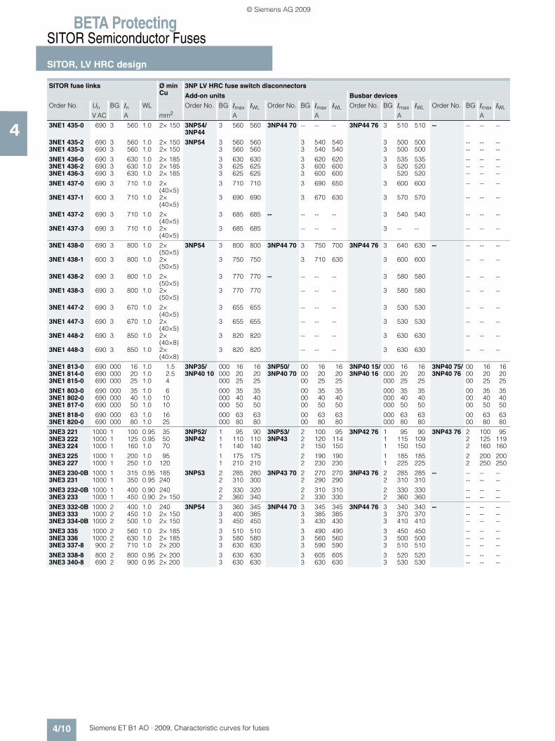
BETA ProtectingSITOR Semiconductor Fuses
SITOR, LV HRC design
4/10 Siemens ET B1 AO · 2009, Characteristic curves for fuses
4 3NE1 435-0 690 3 560 1.0 2× 150 3NP54/3NP44
3 560 560 3NP44 70 -- -- -- 3NP44 76 3 510 510 -- -- -- --
3NE1 435-2 690 3 560 1.0 2× 150 3NP54 3 560 560 3 540 540 3 500 500 -- -- --3NE1 435-3 690 3 560 1.0 2× 150 3 560 560 3 540 540 3 500 500 -- -- --
3NE1 436-0 690 3 630 1.0 2× 185 3 630 630 3 620 620 3 535 535 -- -- --3NE1 436-2 690 3 630 1.0 2× 185 3 625 625 3 600 600 3 520 520 -- -- --3NE1 436-3 690 3 630 1.0 2× 185 3 625 625 3 600 600 520 520 -- -- --
3NE1 437-0 690 3 710 1.0 2×(40×5)
3 710 710 3 690 650 3 600 600 -- -- --
3NE1 437-1 600 3 710 1.0 2×(40×5)
3 690 690 3 670 630 3 570 570 -- -- --
3NE1 437-2 690 3 710 1.0 2×(40×5)
3 685 685 -- -- -- -- 3 540 540 -- -- --
3NE1 437-3 690 3 710 1.0 2×(40×5)
3 685 685 -- -- -- 3 -- -- -- -- --
3NE1 438-0 690 3 800 1.0 2×(50×5)
3NP54 3 800 800 3NP44 70 3 750 700 3NP44 76 3 640 630 -- -- -- --
3NE1 438-1 600 3 800 1.0 2×(50×5)
3 750 750 3 710 630 3 600 600 -- -- --
3NE1 438-2 690 3 800 1.0 2×(50×5)
3 770 770 -- -- -- -- 3 580 580 -- -- --
3NE1 438-3 690 3 800 1.0 2×(50×5)
3 770 770 -- -- -- 3 580 580 -- -- --
3NE1 447-2 690 3 670 1.0 2×(40×5)
3 655 655 -- -- -- 3 530 530 -- -- --
3NE1 447-3 690 3 670 1.0 2×(40×5)
3 655 655 -- -- -- 3 530 530 -- -- --
3NE1 448-2 690 3 850 1.0 2×(40×8)
3 820 820 -- -- -- 3 630 630 -- -- --
3NE1 448-3 690 3 850 1.0 2×(40×8)
3 820 820 -- -- -- 3 630 630 -- -- --
3NE1 813-0 690 000 16 1.0 1.5 3NP35/3NP40 10
000 16 16 3NP50/3NP40 70
00 16 16 3NP40 15/3NP40 16
000 16 16 3NP40 75/3NP40 76
00 16 163NE1 814-0 690 000 20 1.0 2.5 000 20 20 00 20 20 000 20 20 00 20 203NE1 815-0 690 000 25 1.0 4 000 25 25 00 25 25 000 25 25 00 25 25
3NE1 803-0 690 000 35 1.0 6 000 35 35 00 35 35 000 35 35 00 35 353NE1 802-0 690 000 40 1.0 10 000 40 40 00 40 40 000 40 40 00 40 403NE1 817-0 690 000 50 1.0 10 000 50 50 00 50 50 000 50 50 00 50 50
3NE1 818-0 690 000 63 1.0 16 000 63 63 00 63 63 000 63 63 00 63 633NE1 820-0 690 000 80 1.0 25 000 80 80 00 80 80 000 80 80 00 80 80
3NE3 221 1000 1 100 0.95 35 3NP52/3NP42
1 95 90 3NP53/3NP43
2 100 95 3NP42 76 1 95 90 3NP43 76 2 100 953NE3 222 1000 1 125 0.95 50 1 110 110 2 120 114 1 115 109 2 125 1193NE3 224 1000 1 160 1.0 70 1 140 140 2 150 150 1 150 150 2 160 160
3NE3 225 1000 1 200 1.0 95 1 175 175 2 190 190 1 185 185 2 200 2003NE3 227 1000 1 250 1.0 120 1 210 210 2 230 230 1 225 225 2 250 250
3NE3 230-0B 1000 1 315 0.95 185 3NP53 2 285 280 3NP43 70 2 270 270 3NP43 76 2 285 285 -- -- -- --3NE3 231 1000 1 350 0.95 240 2 310 300 2 290 290 2 310 310 -- -- --
3NE3 232-0B 1000 1 400 0.90 240 2 330 320 2 310 310 2 330 330 -- -- --3NE3 233 1000 1 450 0.90 2× 150 2 360 340 2 330 330 2 360 360 -- -- --
3NE3 332-0B 1000 2 400 1.0 240 3NP54 3 360 345 3NP44 70 3 345 345 3NP44 76 3 340 340 -- -- -- --3NE3 333 1000 2 450 1.0 2× 150 3 400 385 3 385 385 3 370 370 -- -- --3NE3 334-0B 1000 2 500 1.0 2× 150 3 450 450 3 430 430 3 410 410 -- -- --
3NE3 335 1000 2 560 1.0 2× 185 3 510 510 3 490 490 3 450 450 -- -- --3NE3 336 1000 2 630 1.0 2× 185 3 580 580 3 560 560 3 500 500 -- -- --3NE3 337-8 900 2 710 1.0 2× 200 3 630 630 3 590 590 3 510 510 -- -- --
3NE3 338-8 800 2 800 0.95 2× 200 3 630 630 3 605 605 3 520 520 -- -- --3NE3 340-8 690 2 900 0.95 2× 200 3 630 630 3 630 630 3 530 530 -- -- --
SITOR fuse links Ø min Cu
3NP LV HRC fuse switch disconnectors
Add-on units Busbar devices
Order No. Un BG In WL Order No. BG Imax IWL Order No. BG Imax IWL Order No. BG Imax IWL Order No. BG Imax IWL
V AC A mm2 A A A A
ET_B1_AO_Kennlinien.book Seite 10 Dienstag, 13. Oktober 2009 11:58 11
© Siemens AG 2009
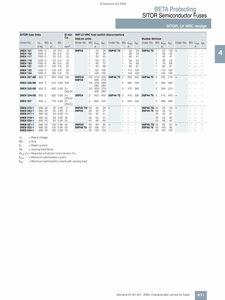
BETA ProtectingSITOR Semiconductor Fuses
SITOR, LV HRC design
4/11Siemens ET B1 AO · 2009, Characteristic curves for fuses
4
Un = Rated voltage
BG = Size
In = Rated current
WL = Varying load factor
Ømin Cu= Required conductor cross-section Cu
Imax = Maximum permissible current
IWL = Maximum permissible current with varying load.
3NE4 101 1000 0 32 0.9 6 3NP52 1 32 29 3NP42 70 1 32 29 3NP42 76 1 32 29 -- -- -- --3NE4 102 1000 0 40 0.9 10 1 40 36 1 38 33 1 38 33 -- -- --3NE4 117 1000 0 50 0.9 10 1 50 45 1 45 41 1 45 41 -- -- --
3NE4 118 1000 0 63 0.9 16 1 63 57 1 59 53 1 59 53 -- -- --3NE4 120 1000 0 80 0.9 25 1 80 72 1 76 68 1 76 68 -- -- --3NE4 121 1000 0 100 0.9 35 1 95 86 1 90 81 1 90 81 -- -- --
3NE4 122 1000 0 125 0.9 50 1 120 108 1 115 104 1 115 104 -- -- --3NE4 124 1000 0 160 0.9 70 1 150 135 1 144 130 1 144 130 -- -- --
3NE4 327-0B 800 2 250 0.85 120 3NP53/3NP54
2/3 210/220
205/210
3NP44 70 3 205 200 3NP44 76 3 235 210 -- -- -- --
3NE4 330-0B 800 2 315 0.85 240 2/3 270/285
255/265
3 260 250 3 280 260 -- -- --
3NE4 333-0B 800 2 450 0.85 2× (30×5)
2/3 400/420
370/380
3 375 360 3 390 370 -- -- --
3NE4 334-0B 800 2 500 0.85 2× (30×5)
3NP54 3 450 400 3NP44 70 3 410 395 3NP44 76 3 415 400 -- -- -- --
3NE4 337 800 2 710 0.95 2× (40×5)
3 600 570 3 540 540 3 480 480 -- -- --
3NE8 015-1 690 00 25 0.95 4 3NP40 70/3NP50
00 25 24 -- -- -- -- 3NP40 75/3NP40 76
00 25 24 -- -- -- --3NE8 003-1 690 00 35 0.95 6 00 33 31 -- -- -- 00 33 31 -- -- --3NE8 017-1 690 00 50 0.90 10 00 45 41 -- -- -- 00 45 41 -- -- --
3NE8 018-1 690 00 63 0.95 16 00 54 51 -- -- -- 00 53 50 -- -- --3NE8 020-1 690 00 80 0.95 25 00 68 65 -- -- -- 00 68 65 -- -- --
3NE8 021-1 690 00 100 0.95 35 3NP50/3NP40 70
00 89 85 -- -- -- -- 3NP40 75/3NP40 76
00 85 81 -- -- -- --3NE8 022-1 690 00 125 0.95 50 00 106 101 -- -- -- 00 100 95 -- -- --3NE8 024-1 690 00 160 0.95 70 00 130 124 -- -- -- 00 125 120 -- -- --
SITOR fuse links Ø min Cu
3NP LV HRC fuse switch disconnectors
Add-on units Busbar devices
Order No. Un BG In WL Order No. BG Imax IWL Order No. BG Imax IWL Order No. BG Imax IWL Order No. BG Imax IWL
V AC A mm2 A A A A
ET_B1_AO_Kennlinien.book Seite 11 Dienstag, 13. Oktober 2009 11:58 11
© Siemens AG 2009
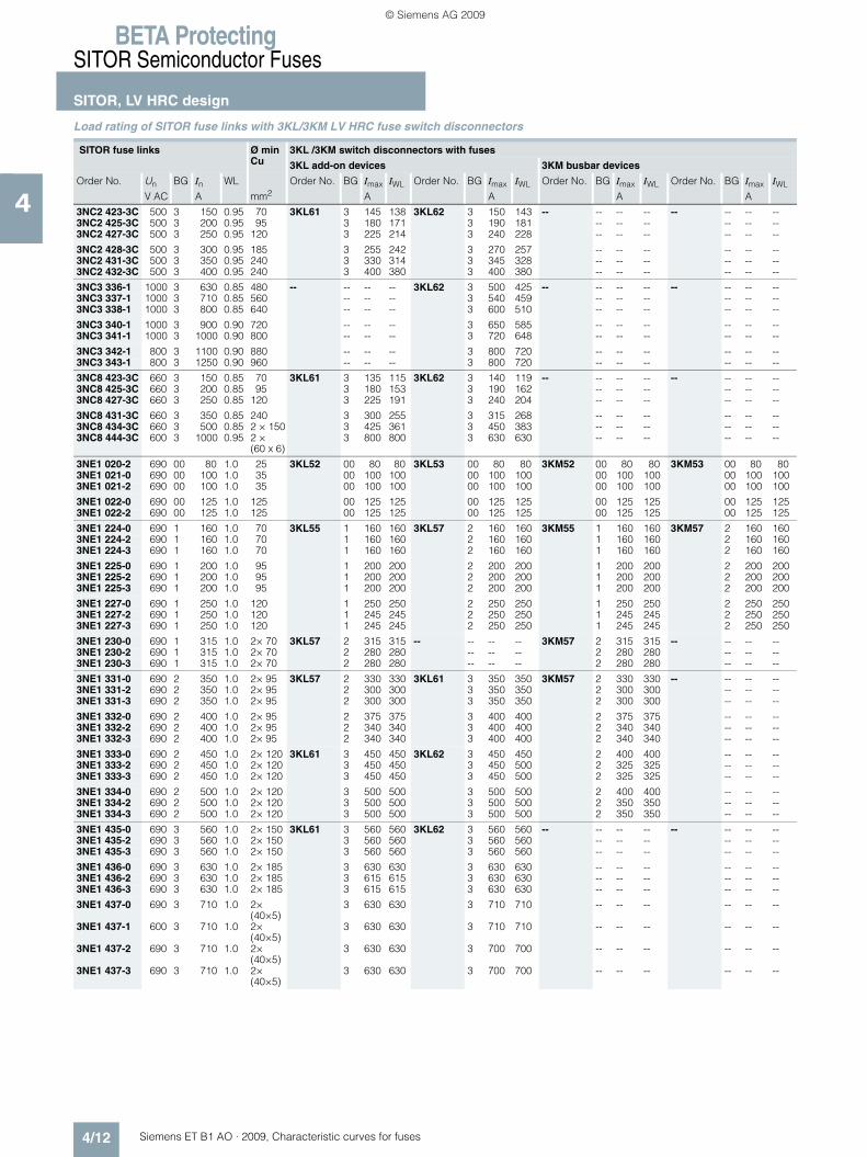
BETA ProtectingSITOR Semiconductor Fuses
SITOR, LV HRC design
4/12 Siemens ET B1 AO · 2009, Characteristic curves for fuses
4
Load rating of SITOR fuse links with 3KL/3KM LV HRC fuse switch disconnectors
SITOR fuse links Ø min Cu
3KL /3KM switch disconnectors with fuses
3KL add-on devices 3KM busbar devices
Order No. Un BG In WL Order No. BG Imax IWL Order No. BG Imax IWL Order No. BG Imax IWL Order No. BG Imax IWL
V AC A mm2 A A A A
3NC2 423-3C 500 3 150 0.95 70 3KL61 3 145 138 3KL62 3 150 143 -- -- -- -- -- -- -- --3NC2 425-3C 500 3 200 0.95 95 3 180 171 3 190 181 -- -- -- -- -- --3NC2 427-3C 500 3 250 0.95 120 3 225 214 3 240 228 -- -- -- -- -- --
3NC2 428-3C 500 3 300 0.95 185 3 255 242 3 270 257 -- -- -- -- -- --3NC2 431-3C 500 3 350 0.95 240 3 330 314 3 345 328 -- -- -- -- -- --3NC2 432-3C 500 3 400 0.95 240 3 400 380 3 400 380 -- -- -- -- -- --
3NC3 336-1 1000 3 630 0.85 480 -- -- -- -- 3KL62 3 500 425 -- -- -- -- -- -- -- --3NC3 337-1 1000 3 710 0.85 560 -- -- -- 3 540 459 -- -- -- -- -- --3NC3 338-1 1000 3 800 0.85 640 -- -- -- 3 600 510 -- -- -- -- -- --
3NC3 340-1 1000 3 900 0.90 720 -- -- -- 3 650 585 -- -- -- -- -- --3NC3 341-1 1000 3 1000 0.90 800 -- -- -- 3 720 648 -- -- -- -- -- --
3NC3 342-1 800 3 1100 0.90 880 -- -- -- 3 800 720 -- -- -- -- -- --3NC3 343-1 800 3 1250 0.90 960 -- -- -- 3 800 720 -- -- -- -- -- --
3NC8 423-3C 660 3 150 0.85 70 3KL61 3 135 115 3KL62 3 140 119 -- -- -- -- -- -- -- --3NC8 425-3C 660 3 200 0.85 95 3 180 153 3 190 162 -- -- -- -- -- --3NC8 427-3C 660 3 250 0.85 120 3 225 191 3 240 204 -- -- -- -- -- --
3NC8 431-3C 660 3 350 0.85 240 3 300 255 3 315 268 -- -- -- -- -- --3NC8 434-3C 660 3 500 0.85 2 × 150 3 425 361 3 450 383 -- -- -- -- -- --3NC8 444-3C 600 3 1000 0.95 2 ×
(60 x 6)3 800 800 3 630 630 -- -- -- -- -- --
3NE1 020-2 690 00 80 1.0 25 3KL52 00 80 80 3KL53 00 80 80 3KM52 00 80 80 3KM53 00 80 803NE1 021-0 690 00 100 1.0 35 00 100 100 00 100 100 00 100 100 00 100 1003NE1 021-2 690 00 100 1.0 35 00 100 100 00 100 100 00 100 100 00 100 100
3NE1 022-0 690 00 125 1.0 125 00 125 125 00 125 125 00 125 125 00 125 1253NE1 022-2 690 00 125 1.0 125 00 125 125 00 125 125 00 125 125 00 125 125
3NE1 224-0 690 1 160 1.0 70 3KL55 1 160 160 3KL57 2 160 160 3KM55 1 160 160 3KM57 2 160 1603NE1 224-2 690 1 160 1.0 70 1 160 160 2 160 160 1 160 160 2 160 1603NE1 224-3 690 1 160 1.0 70 1 160 160 2 160 160 1 160 160 2 160 160
3NE1 225-0 690 1 200 1.0 95 1 200 200 2 200 200 1 200 200 2 200 2003NE1 225-2 690 1 200 1.0 95 1 200 200 2 200 200 1 200 200 2 200 2003NE1 225-3 690 1 200 1.0 95 1 200 200 2 200 200 1 200 200 2 200 200
3NE1 227-0 690 1 250 1.0 120 1 250 250 2 250 250 1 250 250 2 250 2503NE1 227-2 690 1 250 1.0 120 1 245 245 2 250 250 1 245 245 2 250 2503NE1 227-3 690 1 250 1.0 120 1 245 245 2 250 250 1 245 245 2 250 250
3NE1 230-0 690 1 315 1.0 2× 70 3KL57 2 315 315 -- -- -- -- 3KM57 2 315 315 -- -- -- --3NE1 230-2 690 1 315 1.0 2× 70 2 280 280 -- -- -- 2 280 280 -- -- --3NE1 230-3 690 1 315 1.0 2× 70 2 280 280 -- -- -- 2 280 280 -- -- --
3NE1 331-0 690 2 350 1.0 2× 95 3KL57 2 330 330 3KL61 3 350 350 3KM57 2 330 330 -- -- -- --3NE1 331-2 690 2 350 1.0 2× 95 2 300 300 3 350 350 2 300 300 -- -- --3NE1 331-3 690 2 350 1.0 2× 95 2 300 300 3 350 350 2 300 300 -- -- --
3NE1 332-0 690 2 400 1.0 2× 95 2 375 375 3 400 400 2 375 375 -- -- --3NE1 332-2 690 2 400 1.0 2× 95 2 340 340 3 400 400 2 340 340 -- -- --3NE1 332-3 690 2 400 1.0 2× 95 2 340 340 3 400 400 2 340 340 -- -- --
3NE1 333-0 690 2 450 1.0 2× 120 3KL61 3 450 450 3KL62 3 450 450 2 400 400 -- -- --3NE1 333-2 690 2 450 1.0 2× 120 3 450 450 3 450 500 2 325 325 -- -- --3NE1 333-3 690 2 450 1.0 2× 120 3 450 450 3 450 500 2 325 325 -- -- --
3NE1 334-0 690 2 500 1.0 2× 120 3 500 500 3 500 500 2 400 400 -- -- --3NE1 334-2 690 2 500 1.0 2× 120 3 500 500 3 500 500 2 350 350 -- -- --3NE1 334-3 690 2 500 1.0 2× 120 3 500 500 3 500 500 2 350 350 -- -- --
3NE1 435-0 690 3 560 1.0 2× 150 3KL61 3 560 560 3KL62 3 560 560 -- -- -- -- -- -- -- --3NE1 435-2 690 3 560 1.0 2× 150 3 560 560 3 560 560 -- -- -- -- -- --3NE1 435-3 690 3 560 1.0 2× 150 3 560 560 3 560 560 -- -- -- -- -- --
3NE1 436-0 690 3 630 1.0 2× 185 3 630 630 3 630 630 -- -- -- -- -- --3NE1 436-2 690 3 630 1.0 2× 185 3 615 615 3 630 630 -- -- -- -- -- --3NE1 436-3 690 3 630 1.0 2× 185 3 615 615 3 630 630 -- -- -- -- -- --
3NE1 437-0 690 3 710 1.0 2×(40×5)
3 630 630 3 710 710 -- -- -- -- -- --
3NE1 437-1 600 3 710 1.0 2×(40×5)
3 630 630 3 710 710 -- -- -- -- -- --
3NE1 437-2 690 3 710 1.0 2×(40×5)
3 630 630 3 700 700 -- -- -- -- -- --
3NE1 437-3 690 3 710 1.0 2×(40×5)
3 630 630 3 700 700 -- -- -- -- -- --
ET_B1_AO_Kennlinien.book Seite 12 Dienstag, 13. Oktober 2009 11:58 11
© Siemens AG 2009

BETA ProtectingSITOR Semiconductor Fuses
SITOR, LV HRC design
4/13Siemens ET B1 AO · 2009, Characteristic curves for fuses
4
Un = Rated voltage
BG = Size
In = Rated current
WL = Varying load factor
Ømin Cu= Required conductor cross-section Cu
Imax = Maximum permissible current
IWL = Maximum permissible with varying load.
3NE1 438-0 690 3 800 1.0 2×(50×5)
3KL61 3 630 630 3KL62 3 800 800 -- -- -- -- -- -- -- --
3NE1 438-1 600 3 800 1.0 2×(50×5)
3 630 630 3 800 800 -- -- -- -- -- --
3NE1 438-2 690 3 800 1.0 2×(50×5)
3 630 630 3 760 760 -- -- -- -- -- --
3NE1 438-3 690 3 800 1.0 2×(50×5)
3 630 630 3 760 760 -- -- -- -- -- --
3NE1 447-2 690 3 670 1.0 2×(40×5)
3 630 630 3 670 670 -- -- -- -- -- --
3NE1 447-3 690 3 670 1.0 2×(40×5)
3 630 630 3 670 670 -- -- -- -- -- --
3NE1 448-2 690 3 850 1.0 2×(40×8)
3 630 630 3 790 790 -- -- -- -- -- --
3NE1 448-3 690 3 850 1.0 2×(40×8)
3 630 630 3 790 790 -- -- -- -- -- --
3NE1 813-0 690 000 16 1.0 1.5 3KL50 00 16 16 3KL52 00 16 16 3KM50 00 16 16 3KM52 00 16 163NE1 814-0 690 000 20 1.0 2.5 00 20 20 00 20 20 00 20 20 00 20 203NE1 815-0 690 000 25 1.0 4 00 25 25 00 25 25 00 25 25 00 25 25
3NE1 803-0 690 000 35 1.0 6 00 35 35 00 35 35 00 35 35 00 35 353NE1 802-0 690 000 40 1.0 10 00 40 40 00 40 40 00 40 40 00 40 403NE1 817-0 690 000 50 1.0 10 00 50 50 00 50 50 00 50 50 00 50 503NE1 818-0 690 000 63 1.0 16 00 63 63 00 63 63 00 63 63 00 63 63
3NE1 820-0 690 000 80 1.0 25 3KL52 00 80 80 -- -- -- -- 3KM52 00 80 80 -- -- -- --
3NE3 221 1000 1 100 0.95 35 3KL55 1 90 86 3KL57 2 95 90 3KM55 1 90 86 3KM57 2 95 903NE3 222 1000 1 125 0.95 50 1 110 105 2 115 109 1 110 105 2 115 1093NE3 224 1000 1 160 1.0 70 1 140 140 2 150 150 1 140 140 2 150 150
3NE3 225 1000 1 200 1.0 95 1 175 175 2 180 180 1 175 175 2 180 1803NE3 227 1000 1 250 1.0 120 1 210 210 2 220 220 1 210 210 2 220 220
3NE3 230-0B 1000 1 315 0.95 185 3KL57 2 240 228 -- -- -- -- 3KM57 2 240 228 -- -- -- --3NE3 231 1000 1 350 0.95 240 2 265 252 -- -- -- 2 265 252 -- -- --
3NE3 232-0B 1000 1 400 0.90 240 2 290 261 -- -- -- 2 290 261 -- -- --3NE3 233 1000 1 450 0.90 2× 150 2 320 288 -- -- -- 2 320 288 -- -- --
3NE3 332-0B 1000 2 400 1.0 240 3KL61 3 340 340 3KL62 3 360 360 3KM57 2 290 290 -- -- -- --3NE3 333 1000 2 450 1.0 2× 150 3 380 380 3 400 400 2 320 320 -- -- --3NE3 334-0B 1000 2 500 1.0 2× 150 3 440 440 3 470 470 2 360 360 -- -- --
3NE3 335 1000 2 560 1.0 2× 185 3 500 500 3 530 530 2 400 400 -- -- --3NE3 336 1000 2 630 1.0 2× 185 3 540 540 3 580 580 2 400 400 -- -- --3NE3 337-8 900 2 710 1.0 2× 200 3 600 600 3 640 640 2 400 400 -- -- --
3NE3 338-8 800 2 800 0.95 2× 200 3 630 630 3 720 680 2 400 400 -- -- --3NE3 340-8 690 2 900 0.95 2× 200 3 630 630 3 800 750 2 400 400 -- -- --
3NE4 101 1000 0 32 0.9 6 3KL55 1 32 29 -- -- -- -- 3KM55 1 32 29 -- -- -- --3NE4 102 1000 0 40 0.9 10 1 40 36 -- -- -- 1 40 36 -- -- --3NE4 117 1000 0 50 0.9 10 1 50 45 -- -- -- 1 50 45 -- -- --
3NE4 118 1000 0 63 0.9 16 1 63 57 -- -- -- 1 63 57 -- -- --3NE4 120 1000 0 80 0.9 25 1 80 72 -- -- -- 1 80 72 -- -- --3NE4 121 1000 0 100 0.9 35 1 95 86 -- -- -- 1 95 86 -- -- --
3NE4 122 1000 0 125 0.9 50 1 120 108 -- -- -- 1 120 108 -- -- --3NE4 124 1000 0 160 0.9 70 1 150 135 -- -- -- 1 150 135 -- -- --
3NE4 327-0B 800 2 250 0.85 120 3KL57 2 175 149 3KL61 3 200 170 3KM57 2 175 149 -- -- -- --3NE4 330-0B 800 2 315 0.85 240 2 230 196 3 260 221 2 230 196 -- -- --3NE4 333-0B 800 2 450 0.85 2×
(30×5)2 340 289 3 370 315 2 340 289 -- -- --
3NE4 334-0B 800 2 500 0.85 2× (30×5)
3KL61 3 425 361 3KL62 3 450 375 2 380 323 -- -- --
3NE4 337 800 2 710 0.95 2× (40×5)
3 600 570 3 630 600 2 400 400 -- -- --
3NE8 015-1 690 00 25 0.95 4 3KL50 00 25 24 3KL52 00 25 24 3KM50 00 25 24 3KM52 00 25 243NE8 003-1 690 00 35 0.95 6 00 33 31 00 35 33 00 33 31 00 35 333NE8 017-1 690 00 50 0.90 10 00 45 41 00 50 45 00 45 41 00 50 453NE8 018-1 690 00 63 0.95 16 00 54 51 00 60 57 00 54 51 00 60 57
3NE8 020-1 690 00 80 0.95 25 3KL52 00 68 65 3KL53 00 68 65 3KM52 00 68 65 3KM53 00 68 65
3NE8 021-1 690 00 100 0.95 35 3KL52 00 89 85 3KL53 00 89 85 3KM52 00 89 85 3KM53 00 89 853NE8 022-1 690 00 125 0.95 50 00 106 101 00 106 101 00 106 101 00 106 1013NE8 024-1 690 00 160 0.95 70 00 130 124 00 130 124 00 130 124 00 130 124
SITOR fuse links Ø min Cu
3KL /3KM switch disconnectors with fuses
3KL add-on devices 3KM busbar devices
Order No. Un BG In WL Order No. BG Imax IWL Order No. BG Imax IWL Order No. BG Imax IWL Order No. BG Imax IWL
V AC A mm2 A A A A
ET_B1_AO_Kennlinien.book Seite 13 Dienstag, 13. Oktober 2009 11:58 11
© Siemens AG 2009
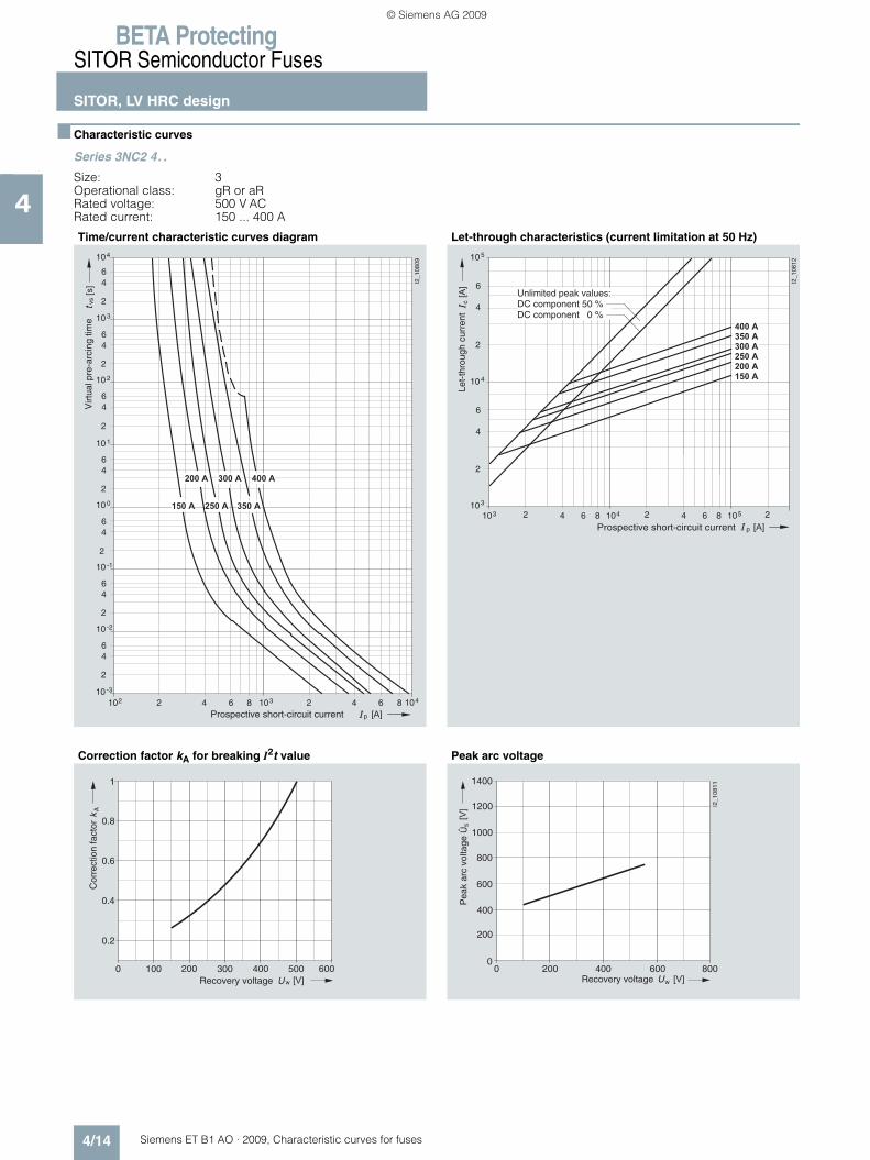
BETA ProtectingSITOR Semiconductor Fuses
SITOR, LV HRC design
4/14 Siemens ET B1 AO · 2009, Characteristic curves for fuses
4
■ Characteristic curves
Series 3NC2 4. .
Size: 3Operational class: gR or aRRated voltage: 500 V ACRated current: 150 ... 400 A
Time/current characteristic curves diagram Let-through characteristics (current limitation at 50 Hz)
Correction factor kA for breaking I2t value Peak arc voltage
210210 -3
2
46
10 -2
64 1038 2 64 1048
2
46
10 -1
2
46
10 0
2
46
10 1
2
46
10 2
2
46
10 3
2
46
104
I2_1
0809
� � � � � � � � �� � � � �
� � �� � � �� � � �
vs
p � � �
���
Virt
ual p
re-a
rcin
g tim
e
Prospective short-circuit current
p
c
103 2 64 104810
2
4
6
10
I2_1
0812
4
3
2 64 1058 2
2
4
6
105
���
� � �
� � � �
� � � � �
� � � �
� � � �
� � �
� � � � �
Prospective short-circuit current
Unlimited peak values:DC component 50 %DC component 0 %
Let-
thro
ugh
curr
ent
0 100 200 300 400 500 600
1
A
w � � �Recovery voltage
Cor
rect
ion
fact
or 0.8
0.6
0.4
0.2
0 200 400 600 800
400
800
1200
s
w
1400
1000
600
200
0
I2_1
0811
� � �
���
Recovery voltage
Pea
k ar
c vo
ltage
Û
ET_B1_AO_Kennlinien.book Seite 14 Dienstag, 13. Oktober 2009 11:58 11
© Siemens AG 2009

BETA ProtectingSITOR Semiconductor Fuses
SITOR, LV HRC design
4/15Siemens ET B1 AO · 2009, Characteristic curves for fuses
4
Series 3NC3 2
Size: 3Operational class: aRRated voltage: 690 V AC (630 ... 1250 A),
500 V AC (1400 ... 1600 A)Rated current: 630 ... 1600 A
Time/current characteristic curves diagram Let-through characteristics
Correction factor kA for breaking I2t value Peak arc voltage
10 4
6
4
2
10 3
6
4
2
10 2
6
4
2
10 1
6 4
2
10 0
6
4
2
10 -1
6
4
2
10 -2
10 10 2 4 6 8 10
-3
2 3 2 4 6 8 10 4 2 4 6 8 10 5
6
4
2
p
vs
I2_
13
40
2
[s]
[A] I
1600 A
1400 A
1250 A
1100 A
1000 A
900 A
800 A
710 A
630 A
t
Permissible
overload
Melting
Prospective short-circuit current
Virtu
al m
eltin
g t
ime
p
c
3
1010 2 4 6 8 410 2 4 6 8 510
2
4
6
10 4
3
2
4
6
10 5
[A]
I
[A]
1600 A
1400 A
1250 A
1100 A
1000 A
900 A
800 A
710 A
630 A
I
I201
_13
40
5a
Prospective short-circuit current
Le
t-th
rou
gh
cu
rre
nt
U 0 100 200 300 400 500 600
1
700 800
w [V]
I2_
13
40
3
= 500 V n U
= 690 V n U
Recovery voltage
0,2
0,4
0,6
0,8
22
Co
rre
ctio
n f
acto
r fo
r b
rea
kin
gva
lue
[A
s]
It
0 200 400 600 800
400
200
600
800
1200
1000
1400
1600
0
I2_
13
40
4
[V]w
[V]
s
U
Û
Recovery voltage
Pe
ak a
rc v
olta
ge
ET_B1_AO_Kennlinien.book Seite 15 Dienstag, 13. Oktober 2009 11:58 11
© Siemens AG 2009

BETA ProtectingSITOR Semiconductor Fuses
SITOR, LV HRC design
4/16 Siemens ET B1 AO · 2009, Characteristic curves for fuses
4
Series 3NC3 3
Size: 3Operational class: aRRated voltage: 1000 V AC (630 ... 1000 A),
800 V AC (1100 ... 1250 A)Rated current: 630 ... 1250 A
Time/current characteristic curves diagram Let-through characteristics
Correction factor kA for breaking I2t value Peak arc voltage
10 4
6
4
2
10 3
6
4
2
10 2
6
4
2
10 1
6 4
2
10 0
6
4
2
10 -1
6
4
2
10 -2
10 10 2 4 6 8 10
-3
2 3 2 4 6 8 10 4 2 4 6 8 10 5
6
4
2
p
vs
I2_
13
40
6
[s]
t
[A] I
1250 A
1100 A
1000 A
900 A
800 A
710 A
630 A
Virtu
al p
re-a
rcin
g t
ime
Prospective short-circuit current
Permissible
overload
Prearcing
p
c
3
10 10 2 4 6 8 4 10 2 4 6 8 5 10
2
4
6
10
I2_
13
40
9
4
3
2
4
6
10 5
[A]
I
[A]
1250 A
1100 A
1000 A
900 A
800 A
710 A
630 A
IProspective short-circuit current
Le
t-th
rou
gh
cu
rre
nt
U 0 200 400 600
1
800 1000
w [V]
I2_
13
40
7
= 800 V n U
= 1000 V n U
22
Corr
ection facto
r fo
r bre
akin
g-v
alu
e [A
s]
It
Recovery voltage
0,2
0,4
0,6
0,8
0 200 400 600 800 1000 1200
400
800
1600
2000
1200
2400
2600
0
I2_
13
40
8
[V] w
[V]
s
U
Û
Recovery voltage
Pe
ak a
rc v
olta
ge
ET_B1_AO_Kennlinien.book Seite 16 Dienstag, 13. Oktober 2009 11:58 11
© Siemens AG 2009

BETA ProtectingSITOR Semiconductor Fuses
SITOR, LV HRC design
4/17Siemens ET B1 AO · 2009, Characteristic curves for fuses
4
Series 3NC3 4
Size: 3Operational class: aRRated voltage: 1250 V AC(315 ... 630 A),
1100 V AC (800 A)Rated current: 315 ... 800 A
Time/current characteristic curves diagram Let-through characteristics
Correction factor kA for breaking I2t value Peak arc voltage
104
6
4
2
103
6
4
2
102
6
4
2
101
64
2
100
6
4
2
10-1
6
4
2
10-2
1010 2 4 6 810
-3
2 3 2 4 6 810 4 2 4 6 810 5
6
4
2
p
vs
I2_
17
06
1
[s]
[A]I
800 A
630 A
500 A
400 A
315 A
tP
ea
k a
rc v
olta
ge
Permissible
overload
Prearcing
Prospective short-circuit current
p
c
3
1010 2 4 6 8 410 2 4 6 8 510
2
4
6
10
I2_
17
05
8
4
3
2
4
6
10 5
[A]
I
[A]
800 A
630 A
500 A
400 A
315 A
IProspective short-circuit current
Le
t-th
rou
gh
cu
rre
nt
Unlimited peak values:
DC component 50 %
DC component 0 %
U200 400 600 800 1000
1
1200 1400
w [V]
I2_
17
05
9
800 A
315 A ... 630 A
Recovery voltage
22
Co
rre
ctio
n f
acto
r fo
r b
rea
kin
gva
lue
[A
s]
It
0 200 400 600 800 1000 1400
500
2000
2500
1000
1500
3000
0
I2_
17
06
0
[V]w
[V]
s
U
Û
1200
Recovery voltage
Pe
ak a
rc v
olta
ge
ET_B1_AO_Kennlinien.book Seite 17 Dienstag, 13. Oktober 2009 11:58 11
© Siemens AG 2009

BETA ProtectingSITOR Semiconductor Fuses
SITOR, LV HRC design
4/18 Siemens ET B1 AO · 2009, Characteristic curves for fuses
4
Series 3NC5 531, 3NC5 8. .
Size: aRRated voltage: 800 V AC (350 A, 630 A),
1000 V AC (600 A, 800 A)Rated current: 350 ... 800 A
Time/current characteristic curves diagram Let-through characteristics (current limitation at 50 Hz)
Correction factor kA for breaking I2t value Peak arc voltage
p
vs
210210 -3
2
46
10 -2
64 1038 2 64 1048 2 4
2
46
10 -1
2
46
10 0
2
46
10 1
2
46
10 2
2
46
10 3
2
46
104
I2_1
1432
6 1058
[s]
[A]
� � � � �� � � �
� � �
� � � � �
Virt
ual p
re-a
rcin
g tim
e
Prospective short-circuit current
c
p [A]
[A] I2
_114
33
103
10
2
4
6
2
4
6
4
105
103
105 2 4104 2 64 82 64 8
� � �
� � � � �
� � � �
� � � � �
Let-
thro
ugh
curr
ent
Prospective short-circuit current
Unlimited peak values:DC component 50 %DC component 0 %
0 200 400 600
1
800 1000
A
w [V]
I2_1
1434
� � �
� � � �� � � � �
� � � � �
Cor
rect
ion
fact
or
0.8
0.6
0.4
0.2
Recovery voltage
0 200 400 600 800 1000 1200
400
1200
1600
2000
0
s
w � � �
���
I2_1
1435
200
600
800
1000
1400
1800
� � � � �
� � � � �
� � �
� � � �
Pea
k ar
c vo
ltage
Recovery voltage
Û
ET_B1_AO_Kennlinien.book Seite 18 Dienstag, 13. Oktober 2009 11:58 11
© Siemens AG 2009

BETA ProtectingSITOR Semiconductor Fuses
SITOR, LV HRC design
4/19Siemens ET B1 AO · 2009, Characteristic curves for fuses
4
Series 3NC7 3. .-2
Operational class: aRRated voltage: 680 V ACRated current: 250 A, 350 A
Time/current characteristic curves diagram Let-through characteristics (current limitation at 50 Hz)
Correction factor kA for breaking I2t value Peak arc voltage
p
vs
210210 -3
2
46
10 -2
64 1038 2 64 1048 2 4
2
46
10 -1
2
46
10 0
2
46
10 1
2
46
10 2
2
46
10 3
2
46
104
I2_1
1449
6 1058
[s]
[A]
� � � �
� � �
Virt
ual p
re-a
rcin
g tim
e
Prospective short-circuit current
c
p [A]
[A] I2
_114
50
103
10
2
4
6
2
4
6
4
105
103
105 2 4104 2 64 82 64 8
� � � �
� � �
Let-
thro
ugh
curr
ent
Prospective short-circuit current
Unlimited peak values:DC component 50 %DC component 0 %
0 100 200 300 400 500 600
1
700 800
A
w � � �
Cor
rect
ion
fact
or
Recovery voltage
0.2
0.4
0.6
0.8
0 200 400 600 800 1000 1200
400
1200
1600
2000
0
s
w � � �
���
I2_1
1452
200
600
800
1000
1400
1800
ÛP
eak
arc
volta
ge
Recovery voltage
ET_B1_AO_Kennlinien.book Seite 19 Dienstag, 13. Oktober 2009 11:58 11
© Siemens AG 2009
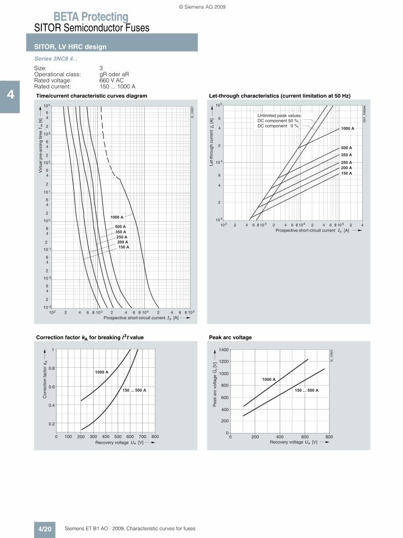
BETA ProtectingSITOR Semiconductor Fuses
SITOR, LV HRC design
4/20 Siemens ET B1 AO · 2009, Characteristic curves for fuses
4
Series 3NC8 4. .
Size: 3Operational class: gR oder aRRated voltage: 660 V ACRated current: 150 ... 1000 A
Time/current characteristic curves diagram Let-through characteristics (current limitation at 50 Hz)
Correction factor kA for breaking I2t value Peak arc voltage
p
vs
210210 -3
2
46
10 -2
64 1038 2 64 1048 2 4
2
46
10 -1
2
46
10 0
2
46
10 1
2
46
10 2
2
46
10 3
2
46
104
I2_1
0821
6 1058
� � � �
� � �
� � � �
� � � � �
� � � � � �
� � � �
� � �
���
Virt
ual p
re-a
rcin
g tim
e
Prospective short-circuit current
10 2 2 64 108
10
2
4
6
2
4
6
4
c
p [A]
[A]
105
10 3
3 2 64 108 4 2 64 108 5 2 4
150 A200 A250 A
350 A
500 A
1000 A
I201
_10
82
4a
Let-
thro
ugh
curr
ent
Prospective short-circuit current
Unlimited peak values:DC component 50 %DC component 0 %
0 100 200 300 400 500 600
1
700 800
A
w
� � � � � �
� � � � � � � � � � �
� � �
Cor
rect
ion
fact
or
Recovery voltage
0.2
0.4
0.6
0.8
0 200 400 600 800
400
800
1200
s
w
1400
1000
600
200
0
I2_1
0823
� � � � � �
� � � � � � � � � � �
� � �
���
Recovery voltage
Pea
k ar
c vo
ltage
Û
ET_B1_AO_Kennlinien.book Seite 20 Dienstag, 13. Oktober 2009 11:58 11
© Siemens AG 2009
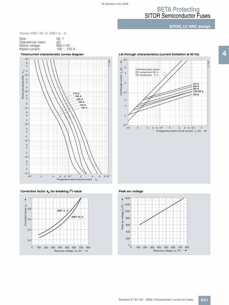
BETA ProtectingSITOR Semiconductor Fuses
SITOR, LV HRC design
4/21Siemens ET B1 AO · 2009, Characteristic curves for fuses
4
Series 3NE1 02.-0, 3NE1 2. .-0
Size: 00, 1Operational class: gSRated voltage: 690 V ACRated current: 100 ... 315 A
Time/current characteristic curves diagram Let-through characteristics (current limitation at 50 Hz)
Correction factor kA for breaking I2t value Peak arc voltage
p
vs
210210 -3
2
46
10 -2
64 1038 2 64 1048
2
46
10 -1
2
46
10 0
2
46
10 1
2
46
10 2
2
46
10 3
2
46
104
I2_1
0829
� � � �
� � � � �
� � � � �
� � � �
� � � � �
� � �
Virt
ual p
re-a
rcin
g tim
e
Prospective short-circuit current
p
c
103 2 64 104810
2
4
6
10
I2_1
0831
4
3
2 64 1058 2
2
4
6
105
���
� � �
� � � � �
� � � � �
� � � �
� � �
� � � � � � � �
Prospective short-circuit current
Unlimited peak values:DC component 50 %DC component 0 %
Let-
thro
ugh
curr
ent
0 100 200 300 400 500 600
1
700 800
A
w
� � � � � � � �
� � � � � � � �
� � �
Cor
rect
ion
fact
or
Recovery voltage
0.2
0.4
0.6
0.8
200 400 500 600 700 800100
s
w
300
1400
1200
1000
800
600
400
200
0� � �
���
0
ÛP
eak
arc
volta
ge
Recovery voltage
ET_B1_AO_Kennlinien.book Seite 21 Dienstag, 13. Oktober 2009 11:58 11
© Siemens AG 2009
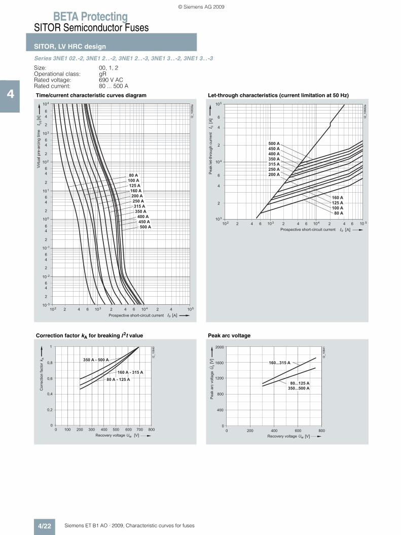
BETA ProtectingSITOR Semiconductor Fuses
SITOR, LV HRC design
4/22 Siemens ET B1 AO · 2009, Characteristic curves for fuses
4
Series 3NE1 02.-2, 3NE1 2. .-2, 3NE1 2. .-3, 3NE1 3. .-2, 3NE1 3. .-3
Size: 00, 1, 2Operational class: gRRated voltage: 690 V ACRated current: 80 ... 500 A
Time/current characteristic curves diagram Let-through characteristics (current limitation at 50 Hz)
Correction factor kA for breaking I2t value Peak arc voltage
10-3
10-2
2
4
6
10-1
2
4
6
100
2
4
6
101
2
4
6
102
2
4
6
103
2
4
6
6
104
2
4
[s]
t VS
2 4
Ap
1052 4 6 1042 4 6 103102
I2_10839a
80 A
100 A
125 A
160 A
200 A
250 A
315 A
350 A
400 A
450 A
500 A
Virtu
al p
re-a
rcin
g t
ime
Prospective short-circuit current
102 103 104 10
A
5103
2
4
6
104
105
2
4
6
A
2 4 6 2 4 6 2 4 6
p
I2_10842a
C
160 A
125 A
100 A
80 A
500 A
450 A
400 A
350 A
315 A
250 A
200 A
Prospective short-circuit current
Pe
ak le
t-th
rou
gh
cu
rre
nt
I2_
10
84
0
0 0
100 200 300 400 500 600 700 800
1
80 A - 125 A
160 A - 315 A
350 A - 500 A
Recovery voltage
Co
rre
ctio
n f
acto
r
0,2
0,4
0,6
0,8
I2_10841
2000
400
800
1200
1600
800 200 0
0
400 600
160...315 A
80...125 A
350...500 A
Pe
ak a
rc v
olta
ge
Recovery voltage
ET_B1_AO_Kennlinien.book Seite 22 Dienstag, 13. Oktober 2009 11:58 11
© Siemens AG 2009

BETA ProtectingSITOR Semiconductor Fuses
SITOR, LV HRC design
4/23Siemens ET B1 AO · 2009, Characteristic curves for fuses
4
Series 3NE1 33.-0, 3NE1 43.-0
Size: 2, 3Operational class: gSRated voltage: 690 V ACRated current: 350 ... 800 A
Time/current characteristic curves diagram Let-through characteristics (current limitation at 50 Hz)
Correction factor kA for breaking I2t value Peak arc voltage
p
vs
210210 -3
2
46
10 -2
64 1038 2 64 1048 2 4
2
46
10 -1
2
46
10 0
2
46
10 1
2
46
10 2
2
46
10 3
2
46
104
I2_1
0832
6 1058
� � � �
� � � �
� � � �
� � � � �
� � �
� � � �
� � � � �
� � � � �
� � �
���
Virt
ual p
re-a
rcin
g tim
e
Prospective short-circuit current
p
c
103 2 64 104810
2
4
6
10
I2_1
0834
4
3
2 64 1058 2
2
4
6
105
���
� � �
� � �
� � � � �
� � � �
� � � �
� � � �
� � � �
� � � � �
� � � � �
Prospective short-circuit current
Unlimited peak values:DC component 50 %DC component 0 %
Let-
thro
ugh
curr
ent
0 100 200 300 400 500 600
1
700 800
A
w � � �
Cor
rect
ion
fact
or
Recovery voltage
0.2
0.4
0.6
0.8
200 400 500 600 700 800100
s
w
300
1400
1200
1000
800
600
400
200
0� � �
���
0
ÛP
eak
arc
volta
ge
Recovery voltage
ET_B1_AO_Kennlinien.book Seite 23 Dienstag, 13. Oktober 2009 11:58 11
© Siemens AG 2009

BETA ProtectingSITOR Semiconductor Fuses
SITOR, LV HRC design
4/24 Siemens ET B1 AO · 2009, Characteristic curves for fuses
4
Series 3NE1 4. .-2, 3NE1 4. .-3
Size: 3Operational class: gRRated voltage: 690 V ACRated current: 560 ... 850 A
Time/current characteristic curves diagram Let-through characteristics (current limitation at 50 Hz)
Correction factor kA for breaking I2t value Peak arc voltage
p
vs
210210 -3
2
46
10 -2
64 1038 2 64 1048 2 4
2
46
10 -1
2
46
10 0
2
46
10 1
2
46
10 2
2
46
10 3
2
46
104
I2_1
0843
6 1058
� � � � �
� � � � �
� � � � �
� � � �
� � � �
� � � �
� � �
���
Virt
ual p
re-a
rcin
g tim
e
Prospective short-circuit current
10 2 10 3 10 4 10 5 10 3
2
4
6
10 4
10 5
2
4
6
2 4 6 2 4 6 2 4 6
p
I2_
10
84
6
C
850 A
800 A
710 A
670 A
630 A
560 A
Prospective short-circuit current
Peak let-
thro
ugh c
urr
ent
0 100 200 300 400 500 600
1
700 800
A
w � � �
Cor
rect
ion
fact
or
Recovery voltage
0.2
0.4
0.6
0.8
0 200w
s
2000
1800
1000
800
400
200
400 600 800
I2_1
0845
600
1200
1400
1600
� � �
���
0
ÛP
eak
arc
volta
ge
Recovery voltage
ET_B1_AO_Kennlinien.book Seite 24 Dienstag, 13. Oktober 2009 11:58 11
© Siemens AG 2009
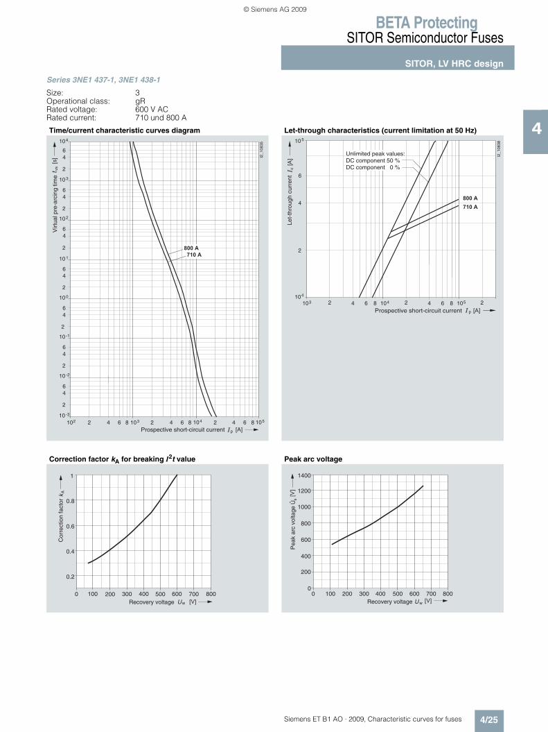
BETA ProtectingSITOR Semiconductor Fuses
SITOR, LV HRC design
4/25Siemens ET B1 AO · 2009, Characteristic curves for fuses
4
Series 3NE1 437-1, 3NE1 438-1
Size: 3Operational class: gRRated voltage: 600 V ACRated current: 710 und 800 A
Time/current characteristic curves diagram Let-through characteristics (current limitation at 50 Hz)
Correction factor kA for breaking I2t value Peak arc voltage
p
vs
210210 -3
2
46
10 -2
64 1038 2 64 1048 2 4
2
46
10 -1
2
46
10 0
2
46
10 1
2
46
10 2
2
46
10 3
2
46
104
I2_1
0835
6 1058
� � � � �
� � � � �
� � �
���
Virt
ual p
re-a
rcin
g tim
e
Prospective short-circuit current
p
c
103 2 64 104810
2
4
6
10
I2_1
0838
5
4
2 64 1058 2
���
� � �
� � � � �
� � � � �
Prospective short-circuit current
Unlimited peak values:DC component 50 %DC component 0 %
Let-
thro
ugh
curr
ent
0 100 200 300 400 500 600
1
700 800
A
w � � �
Cor
rect
ion
fact
or
Recovery voltage
0.2
0.4
0.6
0.8
200 400 500 600 700 800100
s
w
300
1400
1200
1000
800
600
400
200
0� � �
���
0
Pea
k ar
c vo
ltage
Recovery voltage
Û
ET_B1_AO_Kennlinien.book Seite 25 Dienstag, 13. Oktober 2009 11:58 11
© Siemens AG 2009

BETA ProtectingSITOR Semiconductor Fuses
SITOR, LV HRC design
4/26 Siemens ET B1 AO · 2009, Characteristic curves for fuses
4
Series 3NE1 8. .-0
Size: 000Operational class: gSRated voltage: 690 V ACRated current: 16 ... 80 A
Time/current characteristic curves diagram Let-through characteristics (current limitation at 50 Hz)
Correction factor kA for breaking I2t value Peak arc voltage
p
vs
210110 -3
2
46
10 -2
64 1028 2 64 1038 2 4
2
46
10 -1
2
46
10 0
2
46
10 1
2
46
10 2
2
46
10 3
2
46
104
I2_1
0825
6 1048
� � � �
� �
� � �
� � � �
� � � �
� � �
� � �
� � � �
� � �
���
Virt
ual p
re-a
rcin
g tim
e
Prospective short-circuit current
10 2 2 64 108
10
2
4
6
2
4
6
3
c
p [A]
[A]
104
10 2
3 2 64 108 4 2 64 108 5 2 4
20 A25 A35 A40 A50 A63 A
16 A
80 A
I201
_10
82
8a
Let-
thro
ugh
curr
ent
Prospective short-circuit current
Unlimited peak values:DC component 50 %DC component 0 %
0 100 200 300 400 500 600
1
700 800
A
w � � �
Cor
rect
ion
fact
or
Recovery voltage
0.2
0.4
0.6
0.8
200 400 500 600 700 800100
s
w
300
1400
1200
1000
800
600
400
200
0� � �
���
0
ÛP
eak
arc
volta
ge
Recovery voltage
ET_B1_AO_Kennlinien.book Seite 26 Dienstag, 13. Oktober 2009 11:58 11
© Siemens AG 2009

BETA ProtectingSITOR Semiconductor Fuses
SITOR, LV HRC design
4/27Siemens ET B1 AO · 2009, Characteristic curves for fuses
4
Series 3NE3 22.
Size: 1Operational class: aRRated voltage: 1000 V ACRated current: 100 ... 250 A
Time/current characteristic curves diagram Let-through characteristics (current limitation at 50 Hz)
Correction factor kA for breaking I2t value Peak arc voltage
p
vs
210110 -3
2
46
10 -2
64 1028 2 64 1038 2 4
2
46
10 -1
2
46
10 0
2
46
10 1
2
46
10 2
2
46
10 3
2
46
104
I2_1
0859
6 1048
� � � � �
� � � �
� � � � �
���
� � �
� � � � �
� � � �
Virt
ual p
re-a
rcin
g tim
e
Prospective short-circuit current
102 2 64 108
10
2
4
6
2
4
6
3
c
p [A]
[A]
104
102
3 2 64 108 4 2 64 108 5 2 4
I2_1
0862
2
� � � � �
� � � �
� � � � �
� � � � �
� � � �
Let-
thro
ugh
curr
ent
Prospective short-circuit current
Unlimited peak values:DC component 50 %DC component 0 %
0 200 400 600
1
800 1000
A
w � � �
I2_1
0860
Cor
rect
ion
fact
or
0.8
0.6
0.4
0.2
Recovery voltage
0 200 400 600 800 1000 1200
500
1000
1500
2000
2500
0
s
w � � �
���
I2_1
0861
ÛP
eak
arc
volta
ge
Recovery voltage
ET_B1_AO_Kennlinien.book Seite 27 Dienstag, 13. Oktober 2009 11:58 11
© Siemens AG 2009

BETA ProtectingSITOR Semiconductor Fuses
SITOR, LV HRC design
4/28 Siemens ET B1 AO · 2009, Characteristic curves for fuses
4
Series 3NE3 23.
Size: 1Operational class: aRRated voltage: 1000 V ACRated current: 315 ... 450 A
Time/current characteristic curves diagram Let-through characteristics (current limitation at 50 Hz)
Correction factor kA for breaking I2t value Peak arc voltage
I201
_10
86
3a
p
vs
210210 -3
2
46
10 -2
64 10 38 2 64 10 48
2
46
10 -1
2
46
10 0
2
46
10 1
2
46
10 2
2
46
10 3
2
46
10 4
450 A
[A]
400 A350 A315 A
[s]
Vir
tual
pre
-arc
ing
time
Prospective short-circuit current
p
c
103 2 64 104810
2
4
6
10
I2_1
0864
4
3
2 64 1058 2
2
4
6
105
���
� � �
� � �
� � �
� � � � �
� � � �
Prospective short-circuit current
Unlimited peak values:DC component 50 %DC component 0 %
Let-
thro
ugh
curr
ent
0 200 400 600
1
800 1000
A
w � � �
I2_1
0860
Cor
rect
ion
fact
or
0.8
0.6
0.4
0.2
Recovery voltage
0 200 400 600 800 1000 1200
500
1000
1500
2000
2500
0
s
w � � �
���
I2_1
0861
ÛP
eak
arc
volta
ge
Recovery voltage
ET_B1_AO_Kennlinien.book Seite 28 Dienstag, 13. Oktober 2009 11:58 11
© Siemens AG 2009
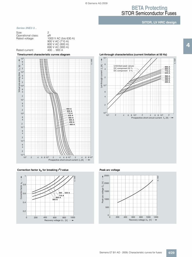
BETA ProtectingSITOR Semiconductor Fuses
SITOR, LV HRC design
4/29Siemens ET B1 AO · 2009, Characteristic curves for fuses
4
Series 3NE3 3. .
Size: 2Operational class: aRRated voltage: 1000 V AC (bis 630 A)
900 V AC (710 A) 800 V AC (800 A) 690 V AC (900 A)
Rated current: 400 ... 900 A
Time/current characteristic curves diagram Let-through characteristics (current limitation at 50 Hz)
Correction factor kA for breaking I2t value Peak arc voltage
p
vs
210210 -3
2
46
10 -2
64 1038 2 64 1048 2 4
2
46
10 -1
2
46
10 0
2
46
10 1
2
46
10 2
2
46
10 3
2
46
104
I2_1
0865
6 1058
� � � � �
� � � �
� � � �
���
� � �
� � � �
� � � �
� � � � �
� � � � �
� � � � �
Virt
ual p
re-a
rcin
g tim
e
Prospective short-circuit current
p
c
103 2 64 104810
2
4
6
� � � � �
10
I2_1
0867
4
3
2 64 1058 2
2
4
6
105
� � � �
� � � �
� � � �
� � � �
� � � � �
� � � � �
� � � � ����
� � �Prospective short-circuit current
Unlimited peak values:DC component 50 %DC component 0 %
Let-
thro
ugh
curr
ent
0 200 400 600
1
800 1000
A
w � � �
I2_1
0866
� � � � �
� � � � �
� � � � � � � � � � � �
� � � � �
Cor
rect
ion
fact
or
0.8
0.6
0.4
0.2
Recovery voltage
0 200 400 600 800 1000 1200
500
1000
1500
2000
2500
0
s
w � � �
���
I2_1
0861
ÛP
eak
arc
volta
ge
Recovery voltage
ET_B1_AO_Kennlinien.book Seite 29 Dienstag, 13. Oktober 2009 11:58 11
© Siemens AG 2009
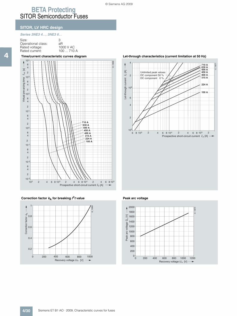
BETA ProtectingSITOR Semiconductor Fuses
SITOR, LV HRC design
4/30 Siemens ET B1 AO · 2009, Characteristic curves for fuses
4
Series 3NE3 4. ., 3NE3 6. .
Size: 3Operational class: aRRated voltage: 1000 V ACRated current: 100 ... 710 A
Time/current characteristic curves diagram Let-through characteristics (current limitation at 50 Hz)
Correction factor kA for breaking I2t value Peak arc voltage
p
vs
210210 -3
2
46
10 -2
64 1038 2 64 1048 2 4
2
46
10 -1
2
46
10 0
2
46
10 1
2
46
10 2
2
46
10 3
2
46
104
I2_1
0868
6 1058
� � � � �
� � � � �
� � �
���
� � �
� � � � �
� � � �
� � � �
� � � �
� � � � �
Virt
ual p
re-a
rcin
g tim
e
Prospective short-circuit current
p
103 2 64 1048
I2_
10
87
1
2 64 1058 2� � �
6 8
� � � � �
� � � � �
� � �
� � � � �
� � � �
� � � �
� � � �
� � � � �
10
2
4
6
104
3
2
4
Prospective short-circuit current
Unlimited peak values:DC component 50 %DC component 0 %
Let-
thro
ugh
curr
ent
c���
0 200 400 600
1
800 1000
A
w � � �
I2_1
0869
Cor
rect
ion
fact
or
0.8
0.6
0.4
0.2
Recovery voltage0 200 400 600 800 1000 1200
400
800
1200
2000
0
s
w � � �
���
I2_1
0870
200
600
1000
1400
1600
1800
Pea
k ar
c vo
ltage
Recovery voltage
Û
ET_B1_AO_Kennlinien.book Seite 30 Dienstag, 13. Oktober 2009 11:58 11
© Siemens AG 2009

BETA ProtectingSITOR Semiconductor Fuses
SITOR, LV HRC design
4/31Siemens ET B1 AO · 2009, Characteristic curves for fuses
4
Series 3NE3 5.5-5, 3NE4 1. .-5
Operational class: aR, gRRated voltage: 800 V AC (170 A)
1000 V AC (50 A, 100 A, 200 A, 450 A)Rated current: 50 ... 450 A
Time/current characteristic curves diagram Let-through characteristics (current limitation at 50 Hz)
Correction factor kA for breaking I2t value Peak arc voltage
p
vs
210110 -3
2
46
10 -2
64 1028 2 64 1038 2 4
2
46
10 -1
2
46
10 0
2
46
10 1
2
46
10 2
2
46
10 3
2
46
104
I2_1
1441
6 1048
[s]
[A]
� � � � �
� � � � � � � � � � � � � � � � �
Virt
ual p
re-a
rcin
g tim
e
Prospective short-circuit current
102 2 64 108
10
2
4
6
3
c
p [A]
[A]
102
3 2 64 108 4 2 64 108 5 2 4
I2_1
1442
10
2
4
6
4
2
4
� � � � �
� � � � �
� � � � �
� � �
� � � �
Let-
thro
ugh
curr
ent
Prospective short-circuit current
Unlimited peak values:DC component 50 %DC component 0 %
0 200 400 600
1
800 1000
A
w [V]
I2_1
1443
� � � � � � �
� � � � �
� � � � � � � �
Cor
rect
ion
fact
or
0.8
0.6
0.4
0.2
Recovery voltage
0 200 400 600 800 1000 1200
400
1200
1600
2000
0
s
w � � �
���
I2_1
1444
200
600
800
1000
1400
1800
� � � � �
� � � � �
ÛP
eak
arc
volta
ge
Recovery voltage
ET_B1_AO_Kennlinien.book Seite 31 Dienstag, 13. Oktober 2009 11:58 11
© Siemens AG 2009
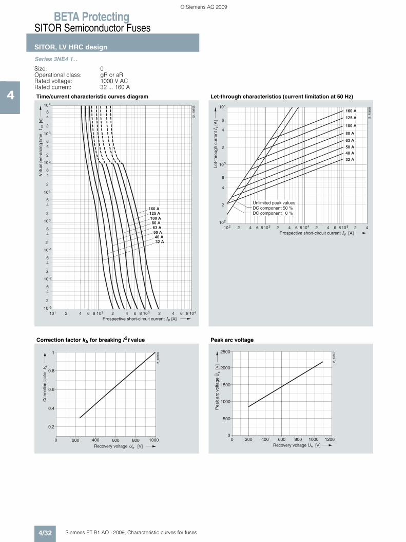
BETA ProtectingSITOR Semiconductor Fuses
SITOR, LV HRC design
4/32 Siemens ET B1 AO · 2009, Characteristic curves for fuses
4
Series 3NE4 1. .
Size: 0Operational class: gR or aRRated voltage: 1000 V ACRated current: 32 ... 160 A
Time/current characteristic curves diagram Let-through characteristics (current limitation at 50 Hz)
Correction factor kA for breaking I2t value Peak arc voltage
p
vs
210110 -3
2
46
10 -2
64 1028 2 64 1038 2 4
2
46
10 -1
2
46
10 0
2
46
10 1
2
46
10 2
2
46
10 3
2
46
104
I2_1
0855
6 1048
� � � � �
� � � �
� � �
� � �
� � � �
� � �
� � � �
� � � � �
���
� � �
Virt
ual p
re-a
rcin
g tim
e
Prospective short-circuit current
102 2 64 108
10
2
4
6
� � � � �
2
4
6
3
� � � �
c
p [A]
[A]
104
102
3 2 64 108 4 2 64 108 5 2 4
� � �
I2_1
0858
� � � �
� � �
� � � � �
� � �
� � � �
Let-
thro
ugh
curr
ent
Prospective short-circuit current
Unlimited peak values:DC component 50 %DC component 0 %
0 200 400 600
1
800 1000
A
w � � �
I2_1
0856
Cor
rect
ion
fact
or
0.8
0.6
0.4
0.2
Recovery voltage
0 200 400 600 800 1000 1200
500
1000
1500
2000
2500
0
s
w � � �
���
I2_1
0857
Pea
k ar
c vo
ltage
Recovery voltage
Û
ET_B1_AO_Kennlinien.book Seite 32 Dienstag, 13. Oktober 2009 11:58 11
© Siemens AG 2009

BETA ProtectingSITOR Semiconductor Fuses
SITOR, LV HRC design
4/33Siemens ET B1 AO · 2009, Characteristic curves for fuses
4
Series 3NE4 3. .-0B, 3NE4 337
Size: 2Operational class: aRRated voltage: 800 V ACRated current: 250 ... 710 A
Time/current characteristic curves diagram Let-through characteristics (current limitation at 50 Hz)
Correction factor kA for breaking I2t value Peak arc voltage
p
vs
210210 -3
2
46
10 -2
64 1038 2 64 1048 2 4
2
46
10 -1
2
46
10 0
2
46
10 1
2
46
10 2
2
46
10 3
2
46
104
I2_1
0851
6 1058
� � � �
� � �
� � � �
� � � �
� � � � �
� � �
���
Virt
ual p
re-a
rcin
g tim
e
Prospective short-circuit current
p
c
103 2 64 104810
2
4
6
10
I2_1
0854
4
3
2 64 1058 2
2
4
6
105
���
� � �
� � � � �
� � � �
� � � �
� � �
� � � �
Prospective short-circuit current
Unlimited peak values:DC component 50 %DC component 0 %
Let-
thro
ugh
curr
ent
0 100 200 300 400 500 600
1
700 800
A
w
� � � �
� � �
� � �
Cor
rect
ion
fact
or
AD
A94
-500
3a-v
Recovery voltage
0.2
0.4
0.6
0.8
0 200w
s
2000
1800
1000
800
400
200
400 600 800
I2_1
0853
600
1200
1400
1600
1000� � �
���
0
Pea
k ar
c vo
ltage
Recovery voltage
Û
ET_B1_AO_Kennlinien.book Seite 33 Dienstag, 13. Oktober 2009 11:58 11
© Siemens AG 2009

BETA ProtectingSITOR Semiconductor Fuses
SITOR, LV HRC design
4/34 Siemens ET B1 AO · 2009, Characteristic curves for fuses
4
Series 3NE4 3. .-6B, 3NE4 337-6
Operational class: aRRated voltage: 800 V ACRated current: 250 ... 710 A
Time/current characteristic curves diagram Let-through characteristics (current limitation at 50 Hz)
Correction factor kA for breaking I2t value Peak arc voltage
p
vs
210210 -3
2
46
10 -2
64 1038 2 64 1048 2 4
2
46
10 -1
2
46
10 0
2
46
10 1
2
46
10 2
2
46
10 3
2
46
104
I2_1
1445
6 1058
[s]
[A]
� � � � �
� � � �
� � � �
� � �
� � � �
Virt
ual p
re-a
rcin
g tim
e
Prospective short-circuit current
c
p [A]
[A] I2
_114
46
103
10
2
4
6
2
4
6
4
105
103
105 2 4104 2 64 82 64 8
� � � �
� � �
� � � �
� � � �
� � � � �
Let-
thro
ugh
curr
ent
Prospective short-circuit current
Unlimited peak values:DC component 50 %DC component 0 %
0 100 200 300 400 500 600
1
700 800
A
w � � �
� � �
� � � �
Cor
rect
ion
fact
or
Recovery voltage
0.2
0.4
0.6
0.8
0 200 400 600 800 1000 1200
400
1200
1600
2000
0
s
w � � �
���
I2_1
1448
200
600
800
1000
1400
1800
Pea
k ar
c vo
ltage
Recovery voltage
Û
ET_B1_AO_Kennlinien.book Seite 34 Dienstag, 13. Oktober 2009 11:58 11
© Siemens AG 2009
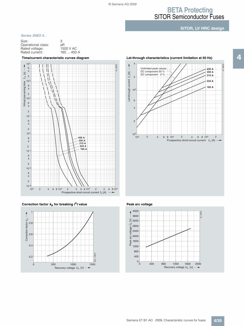
BETA ProtectingSITOR Semiconductor Fuses
SITOR, LV HRC design
4/35Siemens ET B1 AO · 2009, Characteristic curves for fuses
4
Series 3NE5 4. .
Size: 3Operational class: aRRated voltage: 1500 V ACRated current: 160 ... 450 A
Time/current characteristic curves diagram Let-through characteristics (current limitation at 50 Hz)
Correction factor kA for breaking I2t value Peak arc voltage
p
vs
210210 -3
2
46
10 -2
64 1038 2 64 1048 2 4
2
46
10 -1
2
46
10 0
2
46
10 1
2
46
10 2
2
46
10 3
2
46
104
I2_1
0872
6 1058
� � � � �
� � � � �
� � �
���
� � �
� � �
� � � �
Virt
ual p
re-a
rcin
g tim
e
Prospective short-circuit current
p
103 2 64 104
I2_
108
75
2 64 1058 2� � �
8
� � � � �
� � � � �
� � �
� � �
� � � �
2
4
6
104
3
2
4
10
Prospective short-circuit current
Unlimited peak values:DC component 50 %DC component 0 %
Let-
thro
ugh
curr
ent
c���
0 500
1
15001000
w
A
� � �
Cor
rect
ion
fact
or
0.2
0.4
0.6
0.8
I201
_108
73
Recovery voltage
0 400 800 1200 1600 2000
800
2400
4000
0
s
w � � �
���
I2_1
0874
400
1200
2000
2800
3200
3600
1600
Pea
k ar
c vo
ltage
Recovery voltage
Û
ET_B1_AO_Kennlinien.book Seite 35 Dienstag, 13. Oktober 2009 11:58 11
© Siemens AG 2009

BETA ProtectingSITOR Semiconductor Fuses
SITOR, LV HRC design
4/36 Siemens ET B1 AO · 2009, Characteristic curves for fuses
4
Series 3NE5 6. .
Size: 3Operational class: aRRated voltage: 1500 V ACRated current: 250 ... 600 A
Time/current characteristic curves diagram Let-through characteristics (current limitation at 50 Hz)
Correction factor kA for breaking I2t value Peak arc voltage
p
vs
210210 -3
2
46
10 -2
64 1038 2 64 1048 2 4
2
46
10 -1
2
46
10 0
2
46
10 1
2
46
10 2
2
46
10 3
2
46
104
I2_1
0876
6 1058
���
� � �
� � � �
� � � �
� � � � �
Virt
ual p
re-a
rcin
g tim
e
Prospective short-circuit current
p
103 2 64 104
I2_
10
87
7
2 64 1058 2� � �
8
� � � �
� � � �
� � � � �
c���
10
2
4
6
104
3
2
4
Prospective short-circuit current
Unlimited peak values:DC component 50 %DC component 0 %
Let-
thro
ugh
curr
ent
0 500
1
15001000
w
A
� � �
Cor
rect
ion
fact
or
0.2
0.4
0.6
0.8
I201
_108
73
Recovery voltage
0 400 800 1200 1600 2000
800
2400
4000
0
s
w � � �
���
I2_1
0874
400
1200
2000
2800
3200
3600
1600
Pea
k ar
c vo
ltage
Recovery voltage
Û
ET_B1_AO_Kennlinien.book Seite 36 Dienstag, 13. Oktober 2009 11:58 11
© Siemens AG 2009

BETA ProtectingSITOR Semiconductor Fuses
SITOR, LV HRC design
4/37Siemens ET B1 AO · 2009, Characteristic curves for fuses
4
Series 3NE6 4. ., 3NE9 4. .
Operational class: aR, gRRated voltage: 600 V AC (850 A, 1250 A),
900 V AC (710 A, 900 A)Rated current: 710 ... 1250 A
Time/current characteristic curves diagrams
p
vs
210210 -3
2
46
10 -2
64 1038 2 64 1048 2 4
2
46
10 -1
2
46
10 0
2
46
10 1
2
46
10 2
2
46
10 3
2
46
104
I2_1
1436
6 1058
[s]
[A]
� � � �
� � � � �
Virt
ual p
re-a
rcin
g tim
e
Prospective short-circuit current p
vs
210210 -3
2
46
10 -2
64 1038 2 64 1048 2 4
2
46
10 -1
2
46
10 0
2
46
10 1
2
46
10 2
2
46
10 3
2
46
104
I2_1
1437
6 1058
[s]
[A]
� � � � �
� � � � �
Virt
ual p
re-a
rcin
g tim
e
Prospective short-circuit current
ET_B1_AO_Kennlinien.book Seite 37 Dienstag, 13. Oktober 2009 11:58 11
© Siemens AG 2009

BETA ProtectingSITOR Semiconductor Fuses
SITOR, LV HRC design
4/38 Siemens ET B1 AO · 2009, Characteristic curves for fuses
4
Series 3NE6 4. ., 3NE9 4. .
Operational class: aR, gRRated voltage: 600 V AC (850 A, 1250 A),
900 V AC (710 A, 900 A)Rated current: 710 ... 1250 A
Let-through characteristics (current limitation at 50 Hz)
Correction factor kA for breaking I2t value Peak arc voltage
c
p [A]
[A] I2
_114
38
103
10
2
4
6
2
4
6
4
105
103
105 2 4104 2 64 82 64 8
� � � � �
� � � � � � � � � � � �
Let-
thro
ugh
curr
ent
Prospective short-circuit current
Unlimited peak values:DC component 50 %DC component 0 %
0 200 400 600
1
800 1000
A
w [V]
I2_1
1439
� � � � �
� � � � �
� � � � �
� � � � �
Cor
rect
ion
fact
or
0.8
0.6
0.4
0.2
Recovery voltage
0 200 400 600 800 1000 1200
400
1200
1600
2000
0
s
w � � �
���
I2_1
1440
200
600
800
1000
1400
1800
� � � �
� � � � �
� � � � �
� � � � �
Pea
k ar
c vo
ltage
Recovery voltage
Û
ET_B1_AO_Kennlinien.book Seite 38 Dienstag, 13. Oktober 2009 11:58 11
© Siemens AG 2009

BETA ProtectingSITOR Semiconductor Fuses
SITOR, LV HRC design
4/39Siemens ET B1 AO · 2009, Characteristic curves for fuses
4
Series 3NE7 4. ., 3NE7 6. .
Size: 3Operational class: aRRated voltage: 2000 V ACRated current: 200 ... 710 A
Time/current characteristic curves diagram Let-through characteristics (current limitation at 50 Hz)
Correction factor kA for breaking I2t value Peak arc voltage
p
vs
210210 -3
2
46
10 -2
64 1038 2 64 1048 2 4
2
46
10 -1
2
46
10 0
2
46
10 1
2
46
10 2
2
46
10 3
2
46
104
I2_1
0878
6 1058
���
� � �
� � � � �
� � � �
� � �
� � � � �
� � � �
� � �
� � � �
� � � � �
Virt
ual p
re-a
rcin
g tim
e
Prospective short-circuit current
p
c
103 2 64 104810
2
4
6
� � � � �
10
I2_1
0881
4
3
2 64 1058 2
2
4
6
105
� � � �
���
� � �
� � �
� � � � � � � �
� � �
� � � �
� � � � �
Prospective short-circuit current
Unlimited peak values:DC component 50 %DC component 0 %
Let-
thro
ugh
curr
ent
�
0 500
1
15001000
w
A
� � �
2000
I2_1
0879
Cor
rect
ion
fact
or
0.2
0.4
0.6
0.8
Recovery voltage
0 400 800 1200 1600 2000 2400
800
2400
4000
0
s
w � � �
���
I2_1
0880
400
2000
2800
3200
3600
1200
1600
Pea
k ar
c vo
ltage
Recovery voltage
Û
ET_B1_AO_Kennlinien.book Seite 39 Dienstag, 13. Oktober 2009 11:58 11
© Siemens AG 2009

BETA ProtectingSITOR Semiconductor Fuses
SITOR, LV HRC design
4/40 Siemens ET B1 AO · 2009, Characteristic curves for fuses
4
Series 3NE8 0. .-1
Size: 00Operational class: gR or aRRated voltage: 690 V ACRated current: 25 ... 160 A
Time/current characteristic curves diagram Let-through characteristics (current limitation at 50 Hz)
Correction factor kA for breaking I2t value Peak arc voltage
p
vs
210110 -3
2
46
10 -2
64 1028 2 64 1038 2 4
2
46
10 -1
2
46
10 0
2
46
10 1
2
46
10 2
2
46
10 3
2
46
104
I2_1
0847
6 1048
� � � � �
� � � �
� � �
� � �
� �
� � �
� � � �
� � � � �
� � �
���
Virt
ual p
re-a
rcin
g tim
e
Prospective short-circuit current
102 2 64 108
10
2
4
6
2
4
6
3
c
p [A]
[A]
104
102
3 2 64 108 4 2 64 108 5 2 4
� � �
I2_1
0850
� �
� � �
� � �
� � � �
� � � � �
� � � �
� � � � �
Let-
thro
ugh
curr
ent
Prospective short-circuit current
Unlimited peak values:DC component 50 %DC component 0 %
0 100 200 300 400 500 600
1
700 800
A
w � � �
Cor
rect
ion
fact
or
Recovery voltage
0.2
0.4
0.6
0.8
0 200w
s
2000
1800
1000
800
400
200
400 600 800
I2_1
0849
600
1200
1400
1600
� � �
���
0
Pea
k ar
c vo
ltage
Recovery voltage
Û
ET_B1_AO_Kennlinien.book Seite 40 Dienstag, 13. Oktober 2009 11:58 11
© Siemens AG 2009
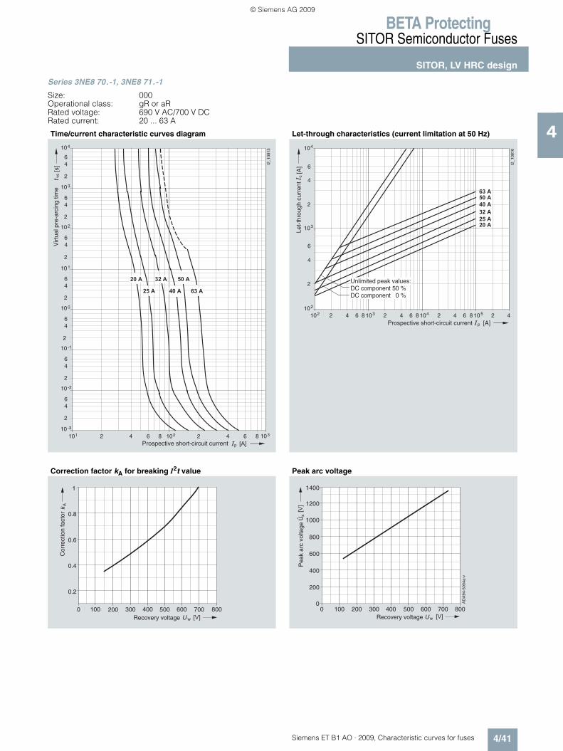
BETA ProtectingSITOR Semiconductor Fuses
SITOR, LV HRC design
4/41Siemens ET B1 AO · 2009, Characteristic curves for fuses
4
Series 3NE8 70.-1, 3NE8 71.-1
Size: 000Operational class: gR or aRRated voltage: 690 V AC/700 V DCRated current: 20 ... 63 A
Time/current characteristic curves diagram Let-through characteristics (current limitation at 50 Hz)
Correction factor kA for breaking I2t value Peak arc voltage
210110 -3
2
46
10 -2
64 1028 2 64 1038
2
46
10 -1
2
46
10 0
2
46
10 1
2
46
10 2
2
46
10 3
2
46
104
I2_1
0813
� � � � � �� � � �
� � �� � � �� � �
vs
p � � �
���
Virt
ual p
re-a
rcin
g tim
e
Prospective short-circuit current
102 2 64 108
10
2
4
6
2
4
6
3
c
p [A]
[A]
104
102
3 2 64 108 4 2 64 108 5 2 4
� � � �
I2_1
0816
� � �
� � �
� � � �
� � �
� � �
Let-
thro
ugh
curr
ent
Prospective short-circuit current
Unlimited peak values:DC component 50 %DC component 0 %
0 100 200 300 400 500 600
1
700 800
A
w � � �
Cor
rect
ion
fact
or
Recovery voltage
0.2
0.4
0.6
0.8
200 400 500 600 700 800100
s
w
300
1400
1200
1000
800
600
400
200
0� � �
���
0
ÛP
eak
arc
volta
ge
AD
A94
-500
4a-v
Recovery voltage
ET_B1_AO_Kennlinien.book Seite 41 Dienstag, 13. Oktober 2009 11:58 11
© Siemens AG 2009

BETA ProtectingSITOR Semiconductor Fuses
SITOR, LV HRC design
4/42 Siemens ET B1 AO · 2009, Characteristic curves for fuses
4
Series 3NE8 72.-1, 3NE8 731-1
Size: 000Operational class: aRRated voltage: 690 V AC/700 V DC acc. to ULRated current: 80 ... 315 A
Time/current characteristic curves diagram Let-through characteristics (current limitation at 50 Hz)
Correction factor kA for breaking I2t value Peak arc voltage
210110 -3
2
46
10 -2
64 1028 2 64 1038 2 4
2
46
10 -1
2
46
10 0
2
46
10 1
2
46
10 2
2
46
10 3
2
46
104
I2_1
0817
6 1048
� � � �
� � � � �
� � � � �
� � � �
� � � � �
� � � �
� � �
vs
p � � �
���
Virt
ual p
re-a
rcin
g tim
e
Prospective short-circuit current
10
2
4
6
2
4
6
4
c[A
]
105
103
I2_1
0820
6
� � � �
� � � � �
� � � �
� � � � �
� � � � �
� � � �
� � �
102 2 64 108 3 2 64 108 4 2 64 108 5 2 4
p [A]
Let-
thro
ugh
curr
ent
Prospective short-circuit current
Unlimited peak values:DC component 50 %DC component 0 %
0 100 200 300 400 500 600
1
700 800
A
w � � �
Cor
rect
ion
fact
or
AD
A94
-500
3a-v
Recovery voltage
0.2
0.4
0.6
0.8
200 400 500 600 700 800100
s
w
300
1400
1200
1000
800
600
400
200
0� � �
���
0
ÛP
eak
arc
volta
ge
Recovery voltage
ET_B1_AO_Kennlinien.book Seite 42 Dienstag, 13. Oktober 2009 11:58 11
© Siemens AG 2009
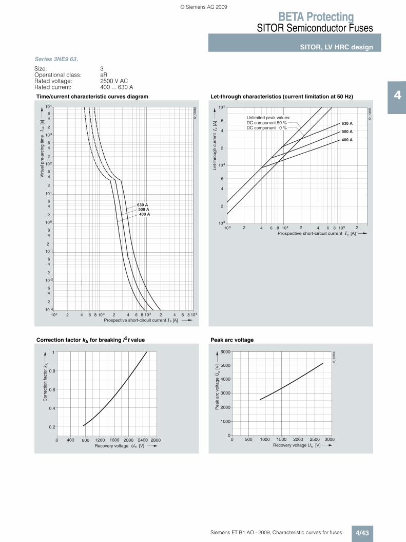
BETA ProtectingSITOR Semiconductor Fuses
SITOR, LV HRC design
4/43Siemens ET B1 AO · 2009, Characteristic curves for fuses
4
Series 3NE9 63.
Size: 3Operational class: aRRated voltage: 2500 V ACRated current: 400 ... 630 A
Time/current characteristic curves diagram Let-through characteristics (current limitation at 50 Hz)
Correction factor kA for breaking I2t value Peak arc voltage
p
vs
210210 -3
2
46
10 -2
64 1038 2 64 1048 2 4
2
46
10 -1
2
46
10 0
2
46
10 1
2
46
10 2
2
46
10 3
2
46
104
I2_1
0882
6 1058
���
� � �
� � � � �
� � � �
� � � �
Virt
ual p
re-a
rcin
g tim
e
Prospective short-circuit current
p
c
103 2 64 104810
2
4
6
10
I2_1
0885
4
3
2 64 1058 2
2
4
6
105
���
� � �
� � � � �
� � � �
� � � �
Prospective short-circuit current
Unlimited peak values:DC component 50 %DC component 0 %
Let-
thro
ugh
curr
ent
0 400 800 1200 1600 2000 2400
1
2800
A
w � � �
Cor
rect
ion
fact
or
Recovery voltage
0.2
0.4
0.6
0.8
0 500 1000 1500 2000 2500 3000
6000
0
s
w � � �
���
I2_1
0884
2000
1000
3000
4000
5000
Pea
k ar
c vo
ltage
Recovery voltage
Û
ET_B1_AO_Kennlinien.book Seite 43 Dienstag, 13. Oktober 2009 11:58 11
© Siemens AG 2009
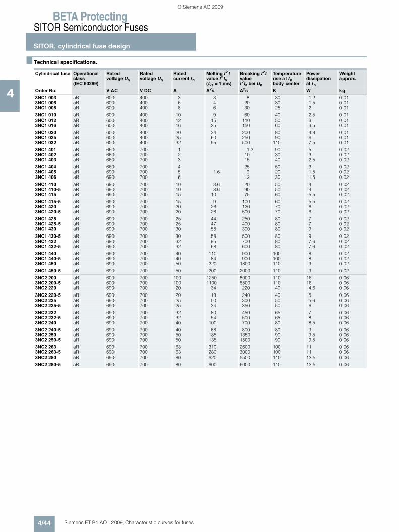
BETA ProtectingSITOR Semiconductor Fuses
SITOR, cylindrical fuse design
4/44 Siemens ET B1 AO · 2009, Characteristic curves for fuses
4
■ Technical specifications.
Cylindrical fuse Operational class (IEC 60269)
Rated voltage Un
Rated voltage Un
Rated current In
Melting I2t value I2ts (tvs = 1 ms)
Breaking I2t value I2ta bei Un
Temperature rise at In body center
Power dissipation at In
Weightapprox.
Order No. V AC V DC A A2s A2s K W kg
3NC1 003 aR 600 400 3 3 8 30 1.2 0.013NC1 006 aR 600 400 6 4 20 30 1.5 0.013NC1 008 aR 600 400 8 6 30 25 2 0.01
3NC1 010 aR 600 400 10 9 60 40 2.5 0.013NC1 012 aR 600 400 12 15 110 50 3 0.013NC1 016 aR 600 400 16 25 150 60 3.5 0.01
3NC1 020 aR 600 400 20 34 200 80 4.8 0.013NC1 025 aR 600 400 25 60 250 90 6 0.013NC1 032 aR 600 400 32 95 500 110 7.5 0.01
3NC1 401 aR 660 700 1 1.2 90 5 0.023NC1 402 aR 660 700 2 10 30 3 0.023NC1 403 aR 660 700 3 15 40 2.5 0.02
3NC1 404 aR 660 700 4 25 50 3 0.023NC1 405 aR 690 700 5 1.6 9 20 1.5 0.023NC1 406 aR 690 700 6 12 30 1.5 0.02
3NC1 410 aR 690 700 10 3.6 20 50 4 0.023NC1 410-5 aR 690 700 10 3.6 90 50 4 0.023NC1 415 aR 690 700 15 10 75 60 5.5 0.02
3NC1 415-5 aR 690 700 15 9 100 60 5.5 0.023NC1 420 aR 690 700 20 26 120 70 6 0.023NC1 420-5 aR 690 700 20 26 500 70 6 0.02
3NC1 425 aR 690 700 25 44 250 80 7 0.023NC1 425-5 aR 690 700 25 47 400 80 7 0.023NC1 430 aR 690 700 30 58 300 80 9 0.02
3NC1 430-5 aR 690 700 30 58 500 80 9 0.023NC1 432 aR 690 700 32 95 700 80 7.6 0.023NC1 432-5 aR 690 700 32 68 600 80 7.6 0.02
3NC1 440 aR 690 700 40 110 900 100 8 0.023NC1 440-5 aR 690 700 40 84 900 100 8 0.023NC1 450 aR 690 700 50 220 1800 110 9 0.02
3NC1 450-5 aR 690 700 50 200 2000 110 9 0.02
3NC2 200 aR 600 700 100 1250 8000 110 16 0.063NC2 200-5 aR 600 700 100 1100 8500 110 16 0.063NC2 220 aR 690 700 20 34 220 40 4.6 0.06
3NC2 220-5 aR 690 700 20 19 240 40 5 0.063NC2 225 aR 690 700 25 50 300 50 5.6 0.063NC2 225-5 aR 690 700 25 34 350 50 6 0.06
3NC2 232 aR 690 700 32 80 450 65 7 0.063NC2 232-5 aR 690 700 32 54 500 65 8 0.063NC2 240 aR 690 700 40 100 700 80 8.5 0.06
3NC2 240-5 aR 690 700 40 68 800 80 9 0.063NC2 250 aR 690 700 50 185 1350 90 9.5 0.063NC2 250-5 aR 690 700 50 135 1500 90 9.5 0.06
3NC2 263 aR 690 700 63 310 2600 100 11 0.063NC2 263-5 aR 690 700 63 280 3000 100 11 0.063NC2 280 aR 690 700 80 620 5500 110 13.5 0.06
3NC2 280-5 aR 690 700 80 600 6000 110 13.5 0.06
ET_B1_AO_Kennlinien.book Seite 44 Dienstag, 13. Oktober 2009 11:58 11
© Siemens AG 2009

BETA ProtectingSITOR Semiconductor Fuses
SITOR, cylindrical fuse design
4/45Siemens ET B1 AO · 2009, Characteristic curves for fuses
4
Load rating of SITOR cylindrical fuses without strikers in fuse holders - can be used as fuse switch disconnectors 1)
Fuse tongs: 3NC1 000.1) Fuse holders according to IEC 60269-3, UL 512,
fuse switch disconnectors (10 × 38, 14 × 51) according to IEC 60947-3,fuse disconnectors (22 × 58) according to IEC 60947-3.
2) The values Imax apply for "stand-alone operation". If several devices are butt-mounted and/or subject to unfavorable cooling conditions, these values may be reduced still further. For larger cross-sections higher values than Imax are possible.
For SITOR fuse links
Rated voltage
Rated current
Required conductor cross-section
Cylindrical fuse bases Fuse holders - can be used as fuse switch disconnectors 1)
1-pole 2-pole 3-pole 1-pole 2-pole 3-poleIn Cu Type Imax Type Imax Type Imax Type Imax Type Imax Type Imax
2) 2) 2) 2) 2) 2)
V AC A mm2 A A A A A A
Size 10 × 38
3NC1 003 600 3 1 3NC1 038-1 3 3NC1038-2/ 2 × 3NC1 038-1
3 3NC1 038-3/ 3 × 3NC1 038-1
3 3NC1 091 3 3NC1 092/ 2 × 3NC1 091
3 3NC1 093/ 3 × 3NC1 091
33NC1 006 6 1 6 6 6 6 6 63NC1 008 8 1 8 8 8 8 8 8
3NC1 010 10 1.5 10 10 10 10 10 103NC1 012 12 1.5 12 12 12 12 12 123NC1 016 16 2.5 16 16 16 16 16 16
3NC1 020 20 2.5 20 20 20 20 20 203NC1 025 25 4 25 23 21 25 24 223NC1 032 32 6 32 30 28 32 30 28
Size 14 × 51
3NC1 401 660 1 1 3NC1 451-1 1 – – 3NC1 491 1 3NC1 492/ 2 × 3NC1 491
1 3NC1 493/ 3 × 3NC1 491
13NC1 402 2 1 2 2 2 2
3NC1 403 3 1 3 3 3 33NC1 404 4 1 4 4 4 4
3NC1 405 690 5 1 5 5 5 53NC1 406 6 1 6 6 6 63NC1 410 10 1.5 10 10 10 10
3NC1 415 15 1.5 15 15 15 153NC1 420 20 2.5 20 20 20 203NC1 425 25 4 25 25 24 22
3NC1 430 30 6 30 28 27 253NC1 432 32 6 32 32 32 323NC1 440 40 10 40 40 39 38
3NC1 450 50 10 50 48 46 44
Size 22 × 58
3NC2 220 690 20 2.5 3NC2 258-1 20 – – 3NC2 291 20 3NC2 292/ 2 × 3NC2 291
20 3NC2 293/ 3 × 3NC2 291
203NC2 225 25 4 25 25 25 253NC2 232 32 6 32 32 32 32
3NC2 240 40 10 40 40 39 383NC2 250 50 10 50 50 48 443NC2 263 63 16 63 60 58 563NC2 280 80 25 80 74 71 69
3NC2 200 600 100 35 100 95 90 85
ET_B1_AO_Kennlinien.book Seite 45 Dienstag, 13. Oktober 2009 11:58 11
© Siemens AG 2009

BETA ProtectingSITOR Semiconductor Fuses
SITOR, cylindrical fuse design
4/46 Siemens ET B1 AO · 2009, Characteristic curves for fuses
4
Load rating of SITOR cylindrical fuses with strikers in fuse holders - can be used as fuse switch disconnectors 1)
1) Fuse holders according to IEC 60269-3, UL 512, fuse switch disconnectors (10 × 38, 14 × 51) according to IEC 60947-3,fuse disconnectors (22 × 58) according to IEC 60947-3.
2) The values Imax apply for "stand-alone operation". If several devices are butt-mounted and/or subject to unfavorable cooling conditions, these values may be reduced still further.For larger cross-sections higher values than Imax are possible.
For SITOR fuse links
Rated voltage Rated current Required conductor cross-section
Fuse holders - can be used as fuse switch disconnectors1)
1-pole 2-pole 3-pole
In Cu Type Imax2) Type Imax
2) Type Imax2)
V AC A mm2 A A A
Size 14 × 51
3NC1 410-5 690 10 1,5 3NC1 491 10 3NC1 492/ 2 × 3NC1 491-5
10 3NC1 493/ 3 × 3NC1 491-5
103NC1 415-5 15 1,5 15 15 153NC1 420-5 20 2,5 20 20 20
3NC1 425-5 25 4 25 25 253NC1 430-5 30 6 30 30 303NC1 432-5 32 6 32 32 31
3NC1 440-5 40 10 38 35 343NC1 450-5 50 10 48 46 44
Size 22 × 58
3NC2 220-5 690 20 2,5 3NC2 291 20 3NC2 292/ 2 × 3NC2 291-5
20 3NC2 293/ 3 × 3NC2 291-5
203NC2 225-5 25 4 25 25 253NC2 232-5 32 6 32 31 30
3NC2 240-5 40 10 40 39 373NC2 250-5 50 10 45 43 423NC2 263-5 63 16 59 55 523NC2 280-5 80 25 71 69 68
3NC2 200-5 600 100 35 94 90 85
ET_B1_AO_Kennlinien.book Seite 46 Dienstag, 13. Oktober 2009 11:58 11
© Siemens AG 2009

BETA ProtectingSITOR Semiconductor Fuses
SITOR, cylindrical fuse design
4/47Siemens ET B1 AO · 2009, Characteristic curves for fuses
4
■ Characteristic curves
Series 3NC1 0
Size: 10 mm × 38 mmOperational class: aRRated voltage: 600 V AC/400 V DCRated current: 3 ... 32 A
Time/current characteristic curves diagram Let-through characteristics (current limitation at 50 Hz)
Correction factor kA for breaking I2t value Peak arc voltage
I2_
11
45
3
10 -3
10 -2
2
4
6
10 -1
2
4
6
10 0
2
4
6
10 1
2
4
6
10 2
2
4
6
10 3
2
4
6
6
10 4
2
4
[s]
t VS
2 4 6
p
10 3 2 4 6 10 2 2 4 6 10 1 10 0
3 A
6 A
8 A
10 A
12 A
16 A
20 A
25 A
32 A
Virtu
al p
re-a
rcin
g t
ime
Prospective short-circuit current
�
� �� ��
�
�
�
�
�
� � � �
���
�
�� �� ��
�� �� ��
�
�����
�
�
�
�
�
�
�
�
�
�
�
� �� � ��
� � � �
� � � �
� � �
� � �
� �
� � � �
� � � �
� � �
� � �
� �
� � � �
� � �
� � �
� �
� � �
� � �
� � � �
� � � �
�� � !"#$%!��$""��
& " # � � � � ' � � � � ! # " � � ' " � $ ' � � $ " " � �
0 100 200 300 400 500 600
1
700 800
A
w � � �
I2_1
1455
Cor
rect
ion
fact
or
Recovery voltage
0.2
0.4
0.6
0.8
0 200 400 600 800
400
800
1200
s
w
1400
1000
600
200
0
I2_1
1456
� � �
���
Recovery voltage
Pea
k ar
c vo
ltage
Û
ET_B1_AO_Kennlinien.book Seite 47 Dienstag, 13. Oktober 2009 11:58 11
© Siemens AG 2009

BETA ProtectingSITOR Semiconductor Fuses
SITOR, cylindrical fuse design
4/48 Siemens ET B1 AO · 2009, Characteristic curves for fuses
4
Series 3NC1 4
Size: 14 mm × 51 mmOperational class: aRRated voltage: 660 V AC/700 V DC (1 ... 4 A);
690 V AC/700 V DC (5 ... 10 A)Rated current: 1 ... 10 A
Time/current characteristic curves diagram Let-through characteristics (current limitation at 50 Hz)
Correction factor kA for breaking I2t value Peak arc voltage
10 -3
10 -2
2
4
6
10 -1
2
4
6
10 0
2
4
6
10 1
2
4
6
10 2
2
4
6
10 3
2
4
6
6
10 4
2
4
[s]
t VS
2 4 6
p
10 3 2 4 6 10 2 2 4 6 10 1 10 0
I2_11459
1 A
2 A
3 A
4 A
5 A
6 A
10 A
Virtu
al P
re-a
rcin
g T
ime
Prospective Short-circuit Current
101 2 64 108
10
2
4
6
c
p [A]
[A]
101
3 2 64 108 4 2 64 108 5
I2_1
1460
10
2
4
6
10
2
4
6
2
3
4
2 64 8102
� �
� � � �
Let-
thro
ugh
curr
ent
Prospective short-circuit current
0 100 200 300 400 500 600
1
700 800
A
w � � �
I2_1
1461
Cor
rect
ion
fact
or
Recovery voltage
0.2
0.4
0.6
0.8
I2_11462
400
800
1200
1600
800 200 0
0
400 600
Pe
ak a
rc v
olta
ge
Recovery voltage
ET_B1_AO_Kennlinien.book Seite 48 Dienstag, 13. Oktober 2009 11:58 11
© Siemens AG 2009
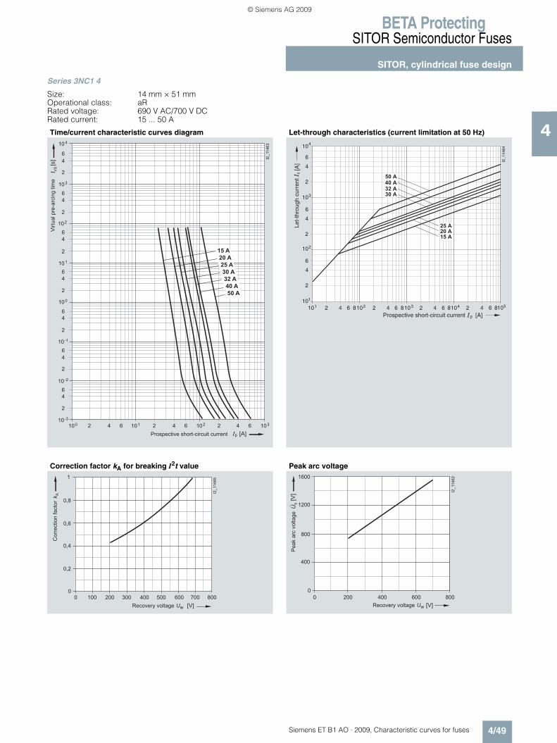
BETA ProtectingSITOR Semiconductor Fuses
SITOR, cylindrical fuse design
4/49Siemens ET B1 AO · 2009, Characteristic curves for fuses
4
Series 3NC1 4
Size: 14 mm × 51 mmOperational class: aRRated voltage: 690 V AC/700 V DCRated current: 15 ... 50 A
Time/current characteristic curves diagram Let-through characteristics (current limitation at 50 Hz)
Correction factor kA for breaking I2t value Peak arc voltage
10 -3
10 -2
2
4
6
10 -1
2
4
6
10 0
2
4
6
10 1
2
4
6
10 2
2
4
6
10 3
2
4
6
6
10 4
2
4
[s]
t VS
2 4 6
p
10 3 2 4 6 10 2 2 4 6 10 1 10 0
I2_
11
46
3
15 A
20 A
25 A
30 A
32 A
40 A
50 A
Virtu
al p
re-a
rcin
g t
ime
Prospective short-circuit current
101 2 64 108
10
2
4
6
c
p [A]
[A]
101
3 2 64 108 4 2 64 108 5
I2_1
1464
10
2
4
6
10
2
4
6
2
3
4
2 64 8102
� � �
� � � �
� � �
� � �
� � � �
� � �
� � �
Let-
thro
ugh
curr
ent
Prospective short-circuit current
0 0
0,2
0,4
0,6
0,8
100 200 300 400 500 600 700 800
1
I2_11465
Recovery voltage
Co
rre
ctio
n f
acto
r
I2_11462
400
800
1200
1600
800 200 0
0
400 600
Pe
ak a
rc v
olta
ge
Recovery voltage
ET_B1_AO_Kennlinien.book Seite 49 Dienstag, 13. Oktober 2009 11:58 11
© Siemens AG 2009

BETA ProtectingSITOR Semiconductor Fuses
SITOR, cylindrical fuse design
4/50 Siemens ET B1 AO · 2009, Characteristic curves for fuses
4
Series 3NC1 4. .-5 with striking pin
Size: 14 mm × 51 mmOperational class: aRRated voltage: 690 V AC/700 V DCRated current: 10 ... 50 A
Time/current characteristic curves diagram Let-through characteristics (current limitation at 50 Hz)
Correction factor kA for breaking I2t value Peak arc voltage
Prospective short-circuit current
Virtu
al p
re-a
rcin
g t
ime
10 -3
10 -2
2
4
6
10 -1
2
4
6
10 0
2
4
6
10 1
2
4
6
10 2
2
4
6
10 3
2
4
6
6
10 4
2
4
[s]
t VS
2 4 6
p
10 3 2 4 6 10 2 2 4 6 10 1 10 0
I2_13410
10 A
15 A
20 A
25 A
30 A
32 A
40 A
50 A
Le
t-th
rou
gh
cu
rre
nt
Prospective short-circuit current
10 1
10 1
10 2
10 3 10 2 10 4 10 5
2
4
6
10 3
2
4
6
10 4
2
4
6
2 4 6 2 4 6 2 4 6 2 4 6
p
I2_13411
C
50 A
40 A
32 A
30 A
25 A
20 A
15 A
10 A
Co
rre
ctio
n f
acto
r
Recovery voltage
0 0
100 200 300 400 500 600 700 800
1
I2_13412
0,2
0,4
0,6
0,8
Pe
ak a
rc v
olta
ge
Recovery voltage
I2_13413
400
600
200
800
1200
1000
1400
8002000
0
400 600
ET_B1_AO_Kennlinien.book Seite 50 Dienstag, 13. Oktober 2009 11:58 11
© Siemens AG 2009
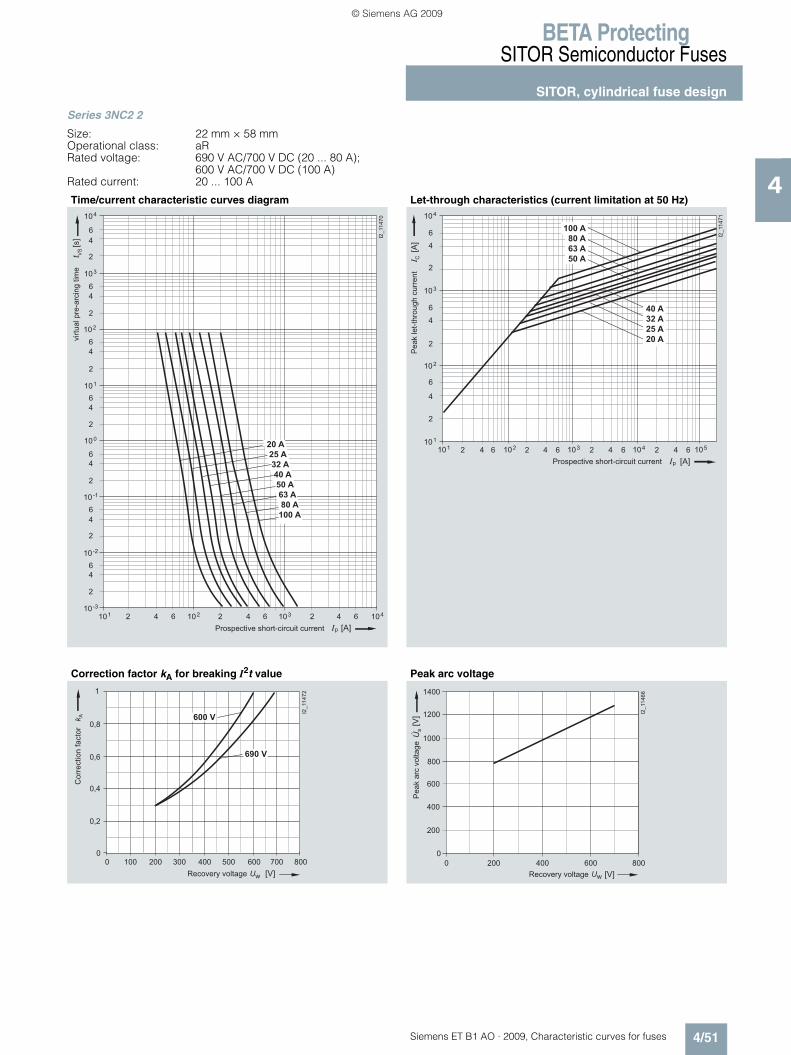
BETA ProtectingSITOR Semiconductor Fuses
SITOR, cylindrical fuse design
4/51Siemens ET B1 AO · 2009, Characteristic curves for fuses
4
Series 3NC2 2
Size: 22 mm × 58 mmOperational class: aRRated voltage: 690 V AC/700 V DC (20 ... 80 A);
600 V AC/700 V DC (100 A)Rated current: 20 ... 100 A
Time/current characteristic curves diagram Let-through characteristics (current limitation at 50 Hz)
Correction factor kA for breaking I2t value Peak arc voltage
10 -3
10 -2
2
4
6
10 -1
2
4
6
10 0
2
4
6
10 1
2
4
6
10 2
2
4
6
10 3
2
4
6
6
10 4
2
4
[s]
t VS
2 4 6
p
10 4 2 4 6 10 3 2 4 6 10 2 10 1
I2_
11
47
0
20 A
25 A
32 A
40 A
50 A
63 A
80 A
100 A
virtu
al p
re-a
rcin
g t
ime
Prospective short-circuit current
10 1
10 1
10 2
10 3 10 2 10 4 10 5
2
4
6
10 3
2
4
6
10 4
2
4
6
2 4 6 2 4 6 2 4 6 2 4 6
p
I2_
11
47
1
C
100 A
80 A
63 A
50 A
40 A
32 A
25 A
20 A
Pe
ak le
t-th
rou
gh
cu
rre
nt
Prospective short-circuit current
0 0
100 200 300 400 500 600 700 800
1
I2_11472
600 V
0,2
0,4
0,6
0,8
690 V
Recovery voltage
Co
rre
ctio
n f
acto
r
I2_11466
400
600
200
800
1200
1000
1400
800 200 0
0
400 600
Pe
ak a
rc v
olta
ge
Recovery voltage
ET_B1_AO_Kennlinien.book Seite 51 Dienstag, 13. Oktober 2009 11:58 11
© Siemens AG 2009

BETA ProtectingSITOR Semiconductor Fuses
SITOR, cylindrical fuse design
4/52 Siemens ET B1 AO · 2009, Characteristic curves for fuses
4
Series 3NC2 2. .-5 with striking pin
Size: 22 mm × 58 mmOperational class: aRRated voltage: 690 V AC/700 V DC (20 ... 80 A);
600 V AC/700 V DC (100 A)Rated current: 20 ... 100 A
Time/current characteristic curves diagram Let-through characteristics (current limitation at 50 Hz)
Correction factor kA for breaking I2t value Peak arc voltage
Prospective short-circuit current
Virtu
al p
re-a
rcin
g t
ime
10 -3
10 -2
2
4
6
10 -1
2
4
6
10 0
2
4
6
10 1
2
4
6
10 2
2
4
6
10 3
2
4
6
6
10 4
2
4
[s]
t VS
2 4 6
p
10 4 2 4 6 10 3 2 4 6 10 2 10 1
I2_13414
20 A
25 A
32 A
40 A
50 A
63 A
80 A
100 A L
et-
thro
ug
h c
urr
en
t
Prospective short-circuit current
10 1
10 1
10 2
10 3 10 2 10 4 10 5
2
4
6
10 3
2
4
6
10 4
2
4
6
2 4 6 2 4 6 2 4 6 2 4 6
p
I2_13415
C
100 A
80 A
63 A
50 A
40 A
32 A
25 A
20 A
Recovery voltage
Co
rre
ctio
n f
acto
r
0,2
0,4
0,6
0,8
0 0
100 200 300 400 500 600 700 800
1
I2_13416
690 V
600 V
Pe
ak a
rc v
olta
ge
Recovery voltage
I2_13417
400
600
200
800
1200
1000
1400
800 200 0
0
400 600
ET_B1_AO_Kennlinien.book Seite 52 Dienstag, 13. Oktober 2009 11:58 11
© Siemens AG 2009
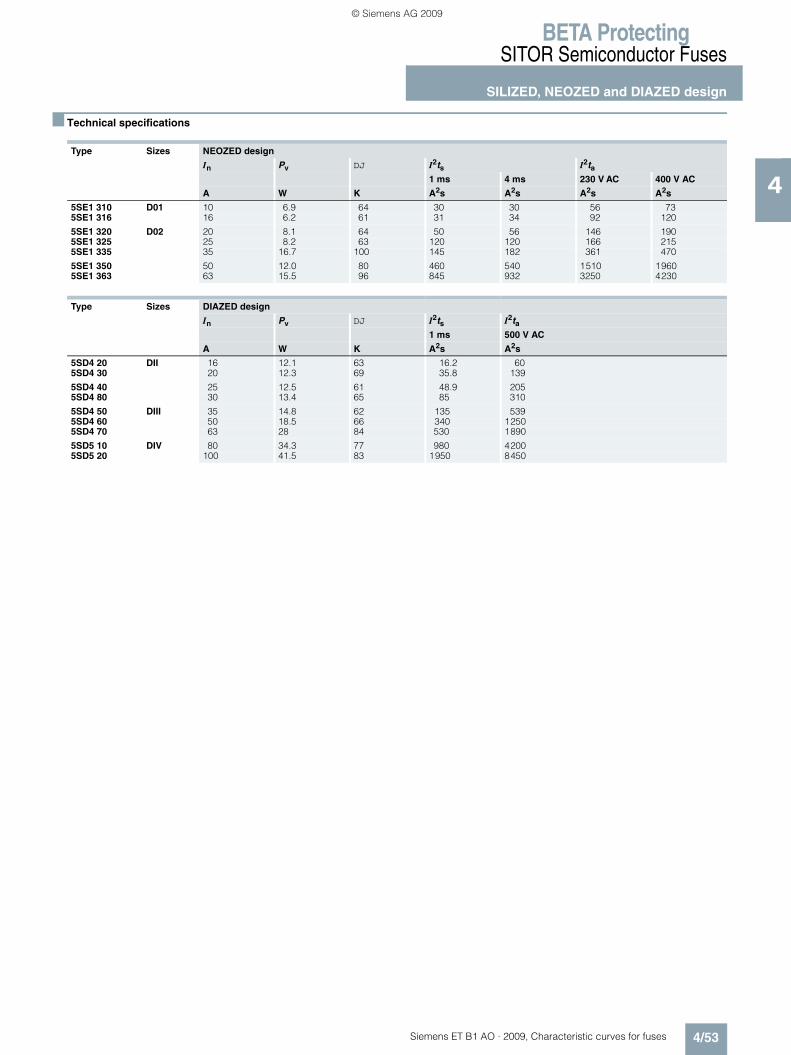
BETA ProtectingSITOR Semiconductor Fuses
SILIZED, NEOZED and DIAZED design
4/53Siemens ET B1 AO · 2009, Characteristic curves for fuses
4
■ Technical specifications
Type Sizes NEOZED design
In Pv DJ I2ts I2ta1 ms 4 ms 230 V AC 400 V AC
A W K A2s A2s A2s A2s
5SE1 310 D01 10 6.9 64 30 30 56 735SE1 316 16 6.2 61 31 34 92 120
5SE1 320 D02 20 8.1 64 50 56 146 1905SE1 325 25 8.2 63 120 120 166 2155SE1 335 35 16.7 100 145 182 361 470
5SE1 350 50 12.0 80 460 540 1510 19605SE1 363 63 15.5 96 845 932 3250 4230
Type Sizes DIAZED design
In Pv DJ I2ts I2ta1 ms 500 V AC
A W K A2s A2s
5SD4 20 DII 16 12.1 63 16.2 605SD4 30 20 12.3 69 35.8 139
5SD4 40 25 12.5 61 48.9 2055SD4 80 30 13.4 65 85 310
5SD4 50 DIII 35 14.8 62 135 5395SD4 60 50 18.5 66 340 12505SD4 70 63 28 84 530 1890
5SD5 10 DIV 80 34.3 77 980 42005SD5 20 100 41.5 83 1950 8450
ET_B1_AO_Kennlinien.book Seite 53 Dienstag, 13. Oktober 2009 11:58 11
© Siemens AG 2009

BETA ProtectingSITOR Semiconductor Fuses
SILIZED, NEOZED and DIAZED design
4/54 Siemens ET B1 AO · 2009, Characteristic curves for fuses
4
■ Characteristic curves
Series 5SE1 3. .
Size: D01, D02Operational class: gRRated voltage: 400 V AC/250 V DCRated current: 10 ... 63 A
Time/current characteristic curves diagram Melting I2ts values diagram
Current limitation diagram
$ Peak short-circuit current with largest DC component
% Peak short-circuit current without DC component
210110 -3
2
46
10 -2
64 10 28 2 64 10 38
2
46
10 -1
2
46
10 0
2
46
10 1
2
46
10 2
2
46
10 3
2
46
10 4
vs
p [A]
[s]
10 A 16 A
20 A
25 A
32/35 A
50 A
63 A
I201
_1147
3a
I201
_1147
5a
2 6 1010 41 2 64 10 28 2 64 10 38 48 2 6 104 5810
2
46
10
2
46
10
2
46
10
2
46
10
2
46
10
2
46
10
0
1
2
3
4
5
6
63 A
50 A
[A]
2s
[A s
]2
10 A16 A20 A
25 A32/35 A
10-1s
10-2s
10-3s
10-4 s
100s
eff
10 2
c
[A]
[A]
10 2
4 6 8 2 10 34 6 8 2 10 44 6 8 2 10 54 6 8
2
4
6
10 3
2
4
6
10 4
50 A63 A
32/35 A25 A20 A16 A10 A
1 2
I201
_11474
a
eff
ET_B1_AO_Kennlinien.book Seite 54 Dienstag, 13. Oktober 2009 11:58 11
© Siemens AG 2009

BETA ProtectingSITOR Semiconductor Fuses
SILIZED, NEOZED and DIAZED design
4/55Siemens ET B1 AO · 2009, Characteristic curves for fuses
4
Series 5SD4, 5SD5
Size: DII, DIII, DIVOperational class: gRCharacteristic: super quickRated voltage: 500 V AC/500 V DCRated current: 16 ... 100 A
Time/current characteristic curves diagram Melting I2ts values diagram
Current limitation diagram
$ Peak short-circuit current with largest DC component
% Peak short-circuit current without DC component
� �
� � �
�
�
�
� � �
�� � �� � �� � ��
�
�
�
� �
�
�
�
� �
�
�
�
�
�
�
�
� �
�
�
�
� �
�
�
�
� �
��������
��
� � � �
���
� � � � � �� � � �
� �� � �� � � � � � �
� � � �
� � � � �
� � � � �� � �� � � � �� � �� ��
�
�
�
�
�
�
�
�
�
�
�
�
�
�
�
�
�
�
�
�
�
�
�
�
�
��� � ��
�
�
�
�
�
�
� � � � � �
��
�����
�
� � �� ��
� � �� � �
�� � �
�� �
��
� � � �
� � � �
� � �
� � �
� � �
� � �
� �
� � � � �
� � � �
� � ��
� � � �� � ��
�
�
��������
�
� � �� � �
���
�
� �� � �� � �� � �� � �
� � � �
� � � �
�
� �
�
�
�
��
� �
� � �
� � �
� �
� � �
� � �
� � � �
� � � � �
ET_B1_AO_Kennlinien.book Seite 55 Dienstag, 13. Oktober 2009 11:58 11
© Siemens AG 2009
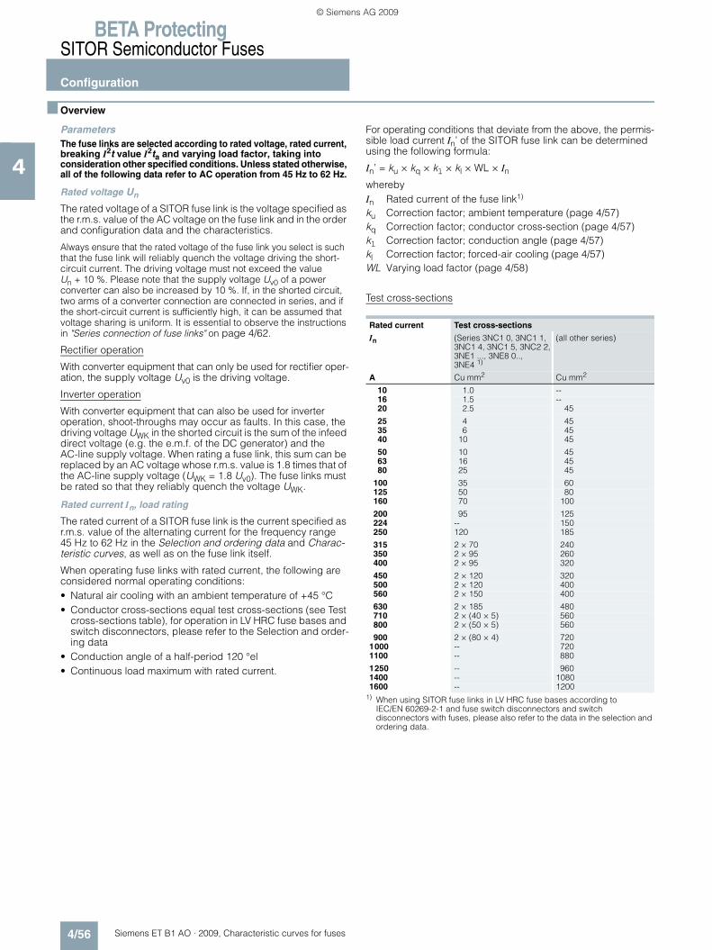
BETA ProtectingSITOR Semiconductor Fuses
Configuration
4/56 Siemens ET B1 AO · 2009, Characteristic curves for fuses
4
■ Overview
ParametersThe fuse links are selected according to rated voltage, rated current, breaking I2t value I2ta and varying load factor, taking into consideration other specified conditions. Unless stated otherwise, all of the following data refer to AC operation from 45 Hz to 62 Hz.
Rated voltage Un
The rated voltage of a SITOR fuse link is the voltage specified as the r.m.s. value of the AC voltage on the fuse link and in the order and configuration data and the characteristics.
Always ensure that the rated voltage of the fuse link you select is such that the fuse link will reliably quench the voltage driving the short-circuit current. The driving voltage must not exceed the value Un + 10 %. Please note that the supply voltage Uv0 of a power converter can also be increased by 10 %. If, in the shorted circuit, two arms of a converter connection are connected in series, and if the short-circuit current is sufficiently high, it can be assumed that voltage sharing is uniform. It is essential to observe the instructions in "Series connection of fuse links" on page 4/62.
Rectifier operation
With converter equipment that can only be used for rectifier oper-ation, the supply voltage Uv0 is the driving voltage.
Inverter operation
With converter equipment that can also be used for inverter operation, shoot-throughs may occur as faults. In this case, the driving voltage UWK in the shorted circuit is the sum of the infeed direct voltage (e.g. the e.m.f. of the DC generator) and the AC-line supply voltage. When rating a fuse link, this sum can be replaced by an AC voltage whose r.m.s. value is 1.8 times that of the AC-line supply voltage (UWK = 1.8 Uv0). The fuse links must be rated so that they reliably quench the voltage UWK.
Rated current In, load rating
The rated current of a SITOR fuse link is the current specified as r.m.s. value of the alternating current for the frequency range 45 Hz to 62 Hz in the Selection and ordering data and Charac-teristic curves, as well as on the fuse link itself.
When operating fuse links with rated current, the following are considered normal operating conditions:• Natural air cooling with an ambient temperature of +45 °C• Conductor cross-sections equal test cross-sections (see Test
cross-sections table), for operation in LV HRC fuse bases and switch disconnectors, please refer to the Selection and order-ing data
• Conduction angle of a half-period 120 °el• Continuous load maximum with rated current.
For operating conditions that deviate from the above, the permis-sible load current In’ of the SITOR fuse link can be determined using the following formula:
In’ = ku × kq × kl × kl × WL × InwherebyIn Rated current of the fuse link1)
ku Correction factor; ambient temperature (page 4/57)kq Correction factor; conductor cross-section (page 4/57)kl Correction factor; conduction angle (page 4/57)kl Correction factor; forced-air cooling (page 4/57)WL Varying load factor (page 4/58)
Test cross-sections
1) When using SITOR fuse links in LV HRC fuse bases according to IEC/EN 60269-2-1 and fuse switch disconnectors and switch disconnectors with fuses, please also refer to the data in the selection and ordering data.
Rated current Test cross-sections
In (Series 3NC1 0, 3NC1 1, 3NC1 4, 3NC1 5, 3NC2 2, 3NE1 ..., 3NE8 0.., 3NE4 1)
(all other series)
A Cu mm2 Cu mm2
10 1.0 --16 1.5 --20 2.5 45
25 4 4535 6 4540 10 45
50 10 4563 16 4580 25 45
100 35 60125 50 80160 70 100
200 95 125224 -- 150250 120 185
315 2 × 70 240350 2 × 95 260400 2 × 95 320
450 2 × 120 320500 2 × 120 400560 2 × 150 400
630 2 × 185 480710 2 × (40 × 5) 560800 2 × (50 × 5) 560
900 2 × (80 × 4) 7201000 -- 7201100 -- 880
1250 -- 9601400 -- 10801600 -- 1200
ET_B1_AO_Kennlinien.book Seite 56 Dienstag, 13. Oktober 2009 11:58 11
© Siemens AG 2009

BETA ProtectingSITOR Semiconductor Fuses
Configuration
4/57Siemens ET B1 AO · 2009, Characteristic curves for fuses
4
Correction factor; ambient temperature ku
The influence of the ambient temperature on the permissible load of the SITOR fuse links is taken into account using the correction factor ku as shown in the following graph.
Correction factor; conductor cross-section kq
The rated current of the SITOR fuse links applies to operation with conductor cross-sections that correspond to the respective test cross-section (see the table on page 4/56).
In the case of reduced conductor cross-sections, the correction factor kq, must be used as shown in the following graph.
a = Reduction of cross-section of one connectionb = Reduction of cross-section of both connections
Correction factor; conduction angle klThe rated current of the SITOR fuse links is based on a sinusoidal alternating current (45 Hz to 62 Hz). However, in converter operation, the arm fuses are loaded with an intermit-tent current, whereby the conduction angle is generally 180 °el or 120 °el. With this load current wave form, the fuse link can still carry the full rated current. In the case of smaller conduction angles, the current must be reduced in accordance with the following graph.
Correction factor; forced-air cooling kl
In the case of increased air cooling, the current carrying capacity of the fuse link increases with the air speed, air speeds > 5 m/s do not effect any significant further increase of current carrying capacity.
� � � � � � � ( � � ( � � ( � � ( � �
� �
� � �
� � �
� �
�
� �
�u
������
Ambient temperature
Cor
rect
ion
fact
or
� � � � � � � � � � � � �
�
� � � �
� � �
� � �
� � � �
� � � �
�
�
� � � �
� � �
� �
� � � �
)
�
�
������
Connection cross-section(as a % of the test cross-section)
Cor
rect
ion
fact
or
� � � � � � � � � � � � � � �
� � �
� � �
� � �
� �
� � �
� � �
�
� � �
� �
�
�����
Valve conducting period
Cor
rect
ion
fact
or
� � �
� � �
� �
�
� �
� �
� �
�*
�������
Air velocity
Cor
rect
ion
fact
or
ET_B1_AO_Kennlinien.book Seite 57 Dienstag, 13. Oktober 2009 11:58 11
© Siemens AG 2009

BETA ProtectingSITOR Semiconductor Fuses
Configuration
4/58 Siemens ET B1 AO · 2009, Characteristic curves for fuses
4
Varying load factor WL
The varying load factor WL is a reduction factor by which the non-aging current carrying capacity of the fuse links can be determined for any load cycle. Due to their design, the SITOR fuse links have different varying load factors. In the characteris-tic curves of the fuse links, the respective varying load factor WL for >10000 load changes (1 hour "ON", 1 hour "OFF") is specified for the expected operating time of the fuse links. In the event of a lower number of load changes during the expected operating time, it may be possible to use a fuse link with a smaller varying load factor WL as shown in the following graph.
In the case of uniform loads (no load cycles and no shutdowns), the varying load factor can be taken as WL = 1. For load cycles and shutdowns that last longer than 5 min. and are more frequent than once a week, you need to select the varying load factor WL specified in the characteristic curves of the individual fuse links.
Waveform of the varying load factor WL for load cycles
Fuse currents for operation in power converter
The r.m.s. value of the fuse current can be calculated for the most common converter connections from the (smoothed) direct current Id or the conductor current IL according to the following table.
101 2 5 102 2 5 103 2 5 104 2 5 105
/LA
n
� � � � � � � �
Permissible number of load cycles
0.6
0.7
0.8
1.1
0.9
1.0 1.0
0.95
0.9
0.85
0.8
Converter connection R.m.s. value of the conductor current(phase fuse)
R.m.s. value of the branch-circuit current(arm fuse)
One-pulse center tap connection (M1) 1.57 Id --
Double-pulse center tap connection (M2) 0.71 Id --
Three-pulse center tap connection (M3) 0.58 Id --
Six-pulse center tap connection (M6) 0.41 Id --
Double three-pulse center tap connection (parallel) (M3.2) 0.29 Id --
Two-pulse bridge circuit (B2) 1.0 Id 0.71 IdSix-pulse bridge circuit (B6) 0.82 Id 0.58 IdSingle-phase bidirectional connection (W1) 1.0 IL 0.71 IL
ET_B1_AO_Kennlinien.book Seite 58 Dienstag, 13. Oktober 2009 11:58 11
© Siemens AG 2009

BETA ProtectingSITOR Semiconductor Fuses
Configuration
4/59Siemens ET B1 AO · 2009, Characteristic curves for fuses
4
I2t values
In the event of a short circuit, the current of the fuse link increases during melting time ts up to let-through current Ic (melting current peak).
During the arc quenching time tL, the electric arc develops and the short-circuit current is quenched (see the following graph).
Current path when switching fuse links
The integral of the current squared over the entire switching
period (ts+tL), known as the breaking I2t value, determines the heat to be fed to the semiconductor device that is to be pro-tected during the breaking procedure.
In order to ensure sufficient protection, the breaking I2t value of the fuse link must be smaller than the I2t value of the semicon-ductor device. As the temperature increases, i.e. preloading in-creases, the breaking I2t value of the fuse link decreases almost in the same way as the I2t value of a semiconductor device, so that it is enough to compare the I2t values in a non-loaded (cold) state.
The breaking I2t value (I2t a) is the sum of the melting I2t value (I2t s) and the quenching I2t value (I2tL).
(semiconductor, tvj = 25 °C,
tp = 10 ms) > (fuse link)
Melting I 2t value I 2tsThe melting value I 2t can be calculated for the value pairs of the time/current characteristic curve of the fuse link for any periods.
As the melting time decreases, the melting value I 2t tends towards a lower limit value at which almost no heat is dissipated from the bottleneck of the fuse element to the environment during the melting process. The melting I 2t values specified in the Selection and ordering data and in the characteristic curves correspond to the melting time tvs = 1 ms.
Quenching I2t value I2tLWhile the melting I2t value is a characteristic of the fuse link, the quenching I2t value depends on circuit data, such as• The recovery voltage Uw • The power factor p.f. of the shorted circuit• The prospective current Ip (current at the installation site of the
fuse link if this is bridged)
The maximum quenching I 2t value is reached at a current of 10 × In to 30 × In.
Breaking I2t value I2ta, correction factor kA
The breaking I2t values of the fuse link are specified in the char-acteristic curves for the rated voltage Un. In order to determine the breaking I2t value for recovery voltage Uw the correction factor ka must be taken into account.
I2ta (at Uw) = I2ta (at Un) x kA
The characteristics "correction factor kA" (see the following graph) is specified in the characteristic curves for the individual fuse series. The breaking I2t values determined in this way apply to prospective currents Ip ‡ 10 x In and p.f. = 0.35.
Correction factor kA for breaking I 2t value Example: Series 3NE8 0..
Taking into account the recovery voltage Uw
The recovery voltage Uw is derived from the voltage driving the short-circuit current. For most faults, the driving voltage is equal to the supply voltage Uv0, however, for shoot-throughs it is 1.8 times the value for the supply voltage Uv0 (see rated voltage, page 4/56). If the shorted circuit contains two arms of a converter connection and thus two fuse links in series, and if the short-circuit current is sufficiently high (see series connection, page 4/62) it can be assumed that there is a uniform voltage sharing, i.e. Uw = 0.5 × Uv0 or, in the case of shoot-throughs Uw = 0.9 × Uv0.
Influence of the power factor
The specifications in the characteristic curves for the breaking I2t values (I2tA) refer to power factor = 0.35 (exception: for 3NC5 8.., 3NE6 4.., 3NE9 4.. SITOR fuse links the following applies: p.f. = 0.2).
The dependence of the breaking I2t values on the power factor at 1.0 × Un and at 0.5 × Un is shown in the following graph.
Dependence of breaking I 2t value I 2ta p.f.
at 1.0 Un at 0.5 Un
a = for 3NC5 8.., 3NE6 4.., 3NE9 4.. SITOR fuse links (reference to p.f. = 0.2)
b = for all other SITOR fuse links (reference to power factor = 0.35).
�
�
�
������
�
�
�
�
I2 tdŁ ł
I2 tdŁI2tAŁ ł
� � � � � � � � � � � � � � � � �
�
� � �
� � �
� � �
� � �
� �
+�
�
������
�
Recovery voltage
Cor
rect
ion
fact
or
� �
� �
� �
� �
�
�
������
�
0.2 0.4 0.6 0.8Power factor p. f.
Cle
anin
g- �
va
lue ��
at p
. f. (
as a
% o
f
at p
. f. =
0.3
5 or
0.2
)
22
A2
A
ET_B1_AO_Kennlinien.book Seite 59 Dienstag, 13. Oktober 2009 11:58 11
© Siemens AG 2009
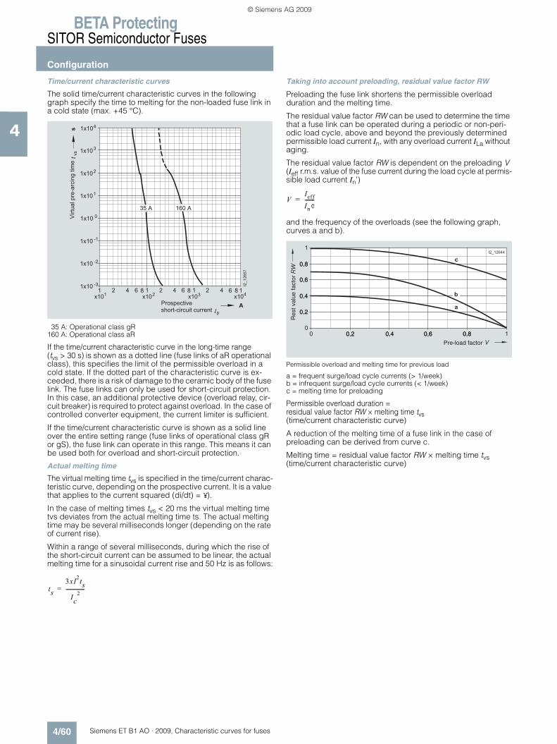
BETA ProtectingSITOR Semiconductor Fuses
Configuration
4/60 Siemens ET B1 AO · 2009, Characteristic curves for fuses
4
Time/current characteristic curves
The solid time/current characteristic curves in the following graph specify the time to melting for the non-loaded fuse link in a cold state (max. +45 °C).
35 A: Operational class gR 160 A: Operational class aR
If the time/current characteristic curve in the long-time range (tvs > 30 s) is shown as a dotted line (fuse links of aR operational class), this specifies the limit of the permissible overload in a cold state. If the dotted part of the characteristic curve is ex-ceeded, there is a risk of damage to the ceramic body of the fuse link. The fuse links can only be used for short-circuit protection. In this case, an additional protective device (overload relay, cir-cuit breaker) is required to protect against overload. In the case of controlled converter equipment, the current limiter is sufficient.
If the time/current characteristic curve is shown as a solid line over the entire setting range (fuse links of operational class gR or gS), the fuse link can operate in this range. This means it can be used both for overload and short-circuit protection.
Actual melting time
The virtual melting time tvs is specified in the time/current charac-teristic curve, depending on the prospective current. It is a value that applies to the current squared (di/dt) = ¥).
In the case of melting times tvs < 20 ms the virtual melting time tvs deviates from the actual melting time ts. The actual melting time may be several milliseconds longer (depending on the rate of current rise).
Within a range of several milliseconds, during which the rise of the short-circuit current can be assumed to be linear, the actual melting time for a sinusoidal current rise and 50 Hz is as follows:
Taking into account preloading, residual value factor RW
Preloading the fuse link shortens the permissible overload duration and the melting time.
The residual value factor RW can be used to determine the time that a fuse link can be operated during a periodic or non-peri-odic load cycle, above and beyond the previously determined permissible load current In, with any overload current ILa without aging.
The residual value factor RW is dependent on the preloading V (Ieff r.m.s. value of the fuse current during the load cycle at permis-sible load current In')
and the frequency of the overloads (see the following graph, curves a and b).
Permissible overload and melting time for previous load
a = frequent surge/load cycle currents (> 1/week) b = infrequent surge/load cycle currents (< 1/week) c = melting time for preloading
Permissible overload duration = residual value factor RW × melting time tvs (time/current characteristic curve)
A reduction of the melting time of a fuse link in the case of preloading can be derived from curve c.
Melting time = residual value factor RW × melting time tvs (time/current characteristic curve)
� � �
�
, �
��
� �
, �� �
, ��
, ��
, �
, ��
, �
, ��
�
, �
, ��
, ��
, ��
� � � � � � � � �
� � � � � � � �
�
�
�����
�
& " # � � � � ' � � �
� ! # " � � ' " � $ ' � � $ " " � �
�'" $�*��"���"�'�%� '-
�
ts3xI2tsIc
2---------------=
VIeff
In¢-------=
�
�
�
�
�
�
� � � � � � � � � � � �
� � �
� � �
� � �
� � �
�
� � � � � �
Pre-load factor
0.2 0.4 0.6 0.8
0.2
0.4
0.6
0.8
Res
t val
ue fa
ctor
ET_B1_AO_Kennlinien.book Seite 60 Dienstag, 13. Oktober 2009 11:58 11
© Siemens AG 2009

BETA ProtectingSITOR Semiconductor Fuses
Configuration
4/61Siemens ET B1 AO · 2009, Characteristic curves for fuses
4
Let-through current Ic
The let-through current Ic can be determined from the current limiting characteristics (current limitation at 50 Hz) specified for the respective fuse link. This depends on the prospective current and the DC component when the short-circuit occurs (instant of closing).
The following graph shows the let-through current Ic of a fuse link, depending on the prospective short-circuit current Ip and using the 3NE4 333-0B SITOR fuse link as an example
Example: 3NE4 333-0B SITOR fuse link
Rated breaking capacity
The rated breaking capacity of all SITOR fuse links is at least 50 kA, unless higher values are specified in the characteristic curves. This data applies to a test voltage of 1.1 × Un, 45 Hz to 62 Hz and 0.1 £p.f. £0.2. In the case of inception voltages that are below the rated voltage, or rated currents of the fuse links that are below the maximum rated current of a fuse series, the breaking capacity is considerably higher than the rated breaking capacity.
Peak arc voltage Ûs
During the quenching process, a peak arc voltage Ûs occurs at the connections of the fuse link, which can significantly exceed the supply voltage. The level of the peak arc voltage depends on the design of the fuse link and the level of the recovery voltage. The characteristic curve shown below depends on the recovery voltage Uw (see the following graph).
Example: 3NE4 333-0B SITOR fuse link
The peak arc voltage occurs as a cutoff voltage at the semicon-ductor devices not in the shorted circuit. In order to prevent voltage-related hazards, the peak arc voltage must not exceed the peak cutoff voltage of the semiconductor devices.
Power dissipation, temperature rise
On reaching the rated current, the fuse elements of the SITOR fuse links have a considerably higher temperature than the fuse elements of line protection fuse links.
The power dissipation specified in the characteristic curve is the upper variance coefficient if the fuse link is loaded with the rated current.
In the case of partial loads, this power dissipation decreases as shown in the following graph.
The temperature rise specified in the characteristic curve applies to the respective reference point and is determined when testing the fuse link (test setup according to DIN VDE 0636, Part 23 and IEC 269-4).
�
�
, � ������
�
, ��
, ��
, ��
, ��
, ��
, ��
, ��
� � � �
�
� � � �
� � � � �
�
& " # � � � � ' � � � � ! # " � � ' " � $ ' � � $ " " � �
. � * ' - ' � � � � � � / � � � * $ � � 0
1 2 � � # - � # � � � � � � 3
1 2 � � # - � # � � � � � � � 3
�� � !"#$%!��$""��
�
0 200 400 600�
800 1000 1200
1000
1400
2000
s�
w
200
400
600
800
1200
1600
1800
�
�
100 ������
Recovery voltage
Pea
k ar
c vo
ltage
100
80
60
40
20
00 20 40 60 80 100
�
�
��������P
ower
dis
sipa
tion
at p
artia
l loa
d(a
s a
% o
f the
pow
erdi
ssip
ated
at r
ated
cur
rent
)
�
Load current(as a % of rated current )
ET_B1_AO_Kennlinien.book Seite 61 Dienstag, 13. Oktober 2009 11:58 11
© Siemens AG 2009

BETA ProtectingSITOR Semiconductor Fuses
Configuration
4/62 Siemens ET B1 AO · 2009, Characteristic curves for fuses
4
Parallel and series connection of fuse links
Parallel connection
If an arm of a converter connection has several semiconductor devices so that the fuse links are connected in parallel, only the fuse link connected in series to the faulty semiconductor device is tripped in the event of an internal short circuit. It must quench the full supply voltage.
To boost the voltage, two or more parallel fuse links can be assigned to a single semiconductor device without reducing the current. The resulting breaking I2t value increases with the square of the number of parallel connections. In this case, in order to prevent incorrect distribution of the current, you should only use fuse links of the same type.
Series connection
There are two kinds of series connection available:• Series connection in the converter arm• 2 fused converter arms through which a short-circuit current
flows in series.
In both cases, uniform voltage sharing can only be assumed if the melting time of the SITOR fuse link does not exceed the value specified in the following table.
Cooling conditions for series-connected fuse links should be approximately the same. If faults are expected, during which the specified melting times are exceeded (as a result of a slower current rise), it can no longer be assumed that voltage sharing is uniform. The voltage of the fuse links must then be rated so that a single fuse link can quench the full supply voltage.
It is best to avoid the series connection of fuse links in a con-verter connection arm and instead use a single fuse link with a suitably high rated voltage.
Use with direct current
For fuse links that are to be used in DC circuits, some data may vary from the data specified in the characteristic curves for alter-nating current.
Permissible direct voltage
The permissible direct voltage Uperm of the fuse links depends on the rated voltage Un, of the time constants t = L/R in the DC circuit and on the prospective current Ip. The permissible direct voltage refers to the rated voltage Un and is specified depend-ing on the time constants t, the prospective current is a param-eter (see the following graphs).
Applies to all series except 3NE1 0.., 3NE1 8..
Applies to all series except 3NE1 0.., 3NE1 8..
Melting I2t value I2taThe breaking I2t value I2ta depends on the voltage, on the time constants t = L/R and on the prospective current Ip. It is calcu-lated from the I2ta value specified in the characteristic curve for the respective fuse link at rated voltage Un and correction factor kA whereby, instead of the recovery voltage Uw, the direct voltage is used against which the fuse link is to switch.
The breaking I2t value determined in this way applies under the following conditions: • Time constants L/R £25 ms for Ip ‡ 20 × In• Time constants L/R £10 ms for Ip = 10 × In • The breaking I2t values increases by 20 % • For Ip ‡ 20 × In and time constants L/R = 60 ms• For Ip = 10 × In and time constants L/R = 35 ms.
SITOR fuse links Maximum melting time for uniform voltage sharing
Type ms
3NC1 0..3NC1 4..3NC1 5..3NC2 2..
10
3NC2 4..
3NC5 8..3NC7 3..3NC8 4..
40
10
3NE1 0..3NE1 2..3NE1 3..
3NE1 4..
3NE1 8..
10
20
10
3NE3 2..3NE3 3..
3NE3 4..3NE3 5..3NE3 6..
10
20
3NE4 1..3NE4 3..
10
3NE5 4..3NE5 6..
20
3NE6 4.. 10
3NE7 4..3NE7 6..
20
3NE8 0..3NE8 7..
10
3NE9 4..
3NE9 6..
10
20
0 10 20 30 40 50 60 70 80
� �
�
20 n
�����
= 10 n
= 5 n
nperm
Time constant
1.00
0.90
0.80
0.70
0.60
0.50
0.40
perm
. DC
vol
tage
U
rate
d vo
ltage
U
= L / R
0 10 20 30 40 50 60 70 80� �
�
������
20 n
= 10 n
= 5 n
Time constant τ = L/R
0.90
0.80
0.70
0.60
0.50
0.40
0.30
perm
. DC
vol
tage
U
rate
d vo
ltage
U (
600
V)
perm
n
ET_B1_AO_Kennlinien.book Seite 62 Dienstag, 13. Oktober 2009 11:58 11
© Siemens AG 2009

BETA ProtectingSITOR Semiconductor Fuses
Configuration
4/63Siemens ET B1 AO · 2009, Characteristic curves for fuses
4
Peak arc voltage Ûs
The peak arc voltage Ûs is determined from the curve specified in the characteristics for the respective fuse link, whereby instead of the recovery voltage Uw, the direct voltage is used against which the fuse link is to switch.
The peak arc voltage determined in this way applies under the following conditions: • Time constants L/R £20 ms for Ip ‡ 20 In• Time constants L/R £35 ms for Ip = 10 In• The switching voltages increase by 20 % • For Ip ‡ 20 In and time constants L/R = 45 ms• For Ip = 10 In and time constants L/R = 60 ms
Indicator
An indicator shows the switching of the fuse link. The indicator of the SITOR fuse links has a transformer operational voltage between 20 V (Un £1000 V) and 40 V (Un > 1000 V).
Accessories
Fuse bases, fuse pullers
Some of the SITOR fuse links can be inserted in matching fuse bases. The matching fuse bases (single-pole and three-pole) and the respective fuse pullers are listed in the technical specifications, from page 4/2.Note: Even if the values of the rated voltage and/or current of the fuse bases are lower than that of the allocated fuse link, the values of the fuse link apply.
Fuse switch disconnectors, switch disconnectors with fuses
Some series of SITOR fuse links are suitable for operation in 3NP4 and 3NP5 fuse switch disconnectors or in 3KL and 3KM switch disconnectors with fuses (see catalogs LV 10 und LV 30).
When using switch disconnectors, the following points must be observed: • Because the power dissipation of SITOR fuse links is higher
than that of LV HRC fuses, the permissible load current of the fuse links sometimes needs to be reduced, see below (Configuration manual)
• Fuse links with rated currents In > 63 A may also not be used for overload protection when they have gR operational class.
Note: All fuse links of the 3NE1 series ... with rated currents In from 16 A to 850 A and gR or gS operational classes can be used for overload protection. • The rated voltage and rated isolation voltage of the switch dis-
connectors must at least correspond to the available voltage. • When using fuse links of the 3NE3 2.., 3NE3 3.., 3NE4 3..,
3NC2 4.. and 3NC8 4.. series the switching capacity of the fuse switch disconnectors must not be fully utilized due to the slotted blade. Occasional switching of currents up to the rated current of the fuse link is permissible
• When used in fuse switch disconnectors, fuse links of the 3NE4 1.. series may only be occasionally switched, and only without load, as this places the fuse blade under great mechanical stress.
In the technical specifications, from page 4/2 the switch discon-nectors are allocated to their respective individual fuse links.
ET_B1_AO_Kennlinien.book Seite 63 Dienstag, 13. Oktober 2009 11:58 11
© Siemens AG 2009
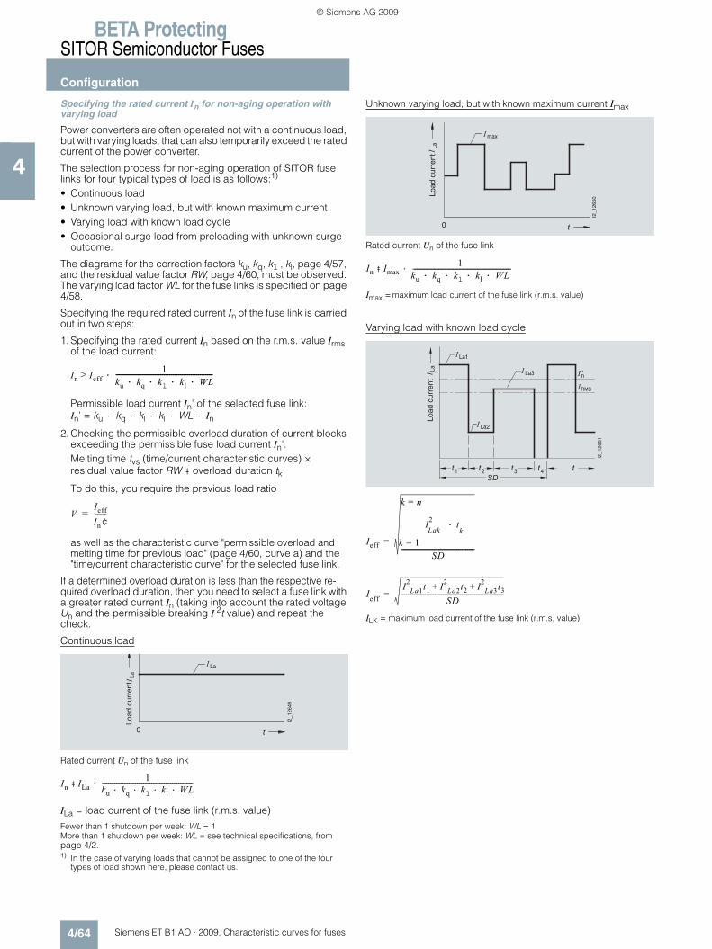
BETA ProtectingSITOR Semiconductor Fuses
Configuration
4/64 Siemens ET B1 AO · 2009, Characteristic curves for fuses
4
Specifying the rated current In for non-aging operation with varying load
Power converters are often operated not with a continuous load, but with varying loads, that can also temporarily exceed the rated current of the power converter.
The selection process for non-aging operation of SITOR fuse links for four typical types of load is as follows:1)
• Continuous load • Unknown varying load, but with known maximum current • Varying load with known load cycle • Occasional surge load from preloading with unknown surge
outcome.
The diagrams for the correction factors ku, kq, kl , kl, page 4/57, and the residual value factor RW, page 4/60, must be observed. The varying load factor WL for the fuse links is specified on page 4/58.
Specifying the required rated current In of the fuse link is carried out in two steps:
1. Specifying the rated current In based on the r.m.s. value Irms of the load current:
Permissible load current In' of the selected fuse link: In’ = ku · kq · kl · kl · WL · In
2. Checking the permissible overload duration of current blocks exceeding the permissible fuse load current In'. Melting time tvs (time/current characteristic curves) × residual value factor RW ‡ overload duration tk
To do this, you require the previous load ratio
as well as the characteristic curve "permissible overload and melting time for previous load" (page 4/60, curve a) and the "time/current characteristic curve" for the selected fuse link.
If a determined overload duration is less than the respective re-quired overload duration, then you need to select a fuse link with a greater rated current In (taking into account the rated voltage Un and the permissible breaking I 2t value) and repeat the check.
Continuous load
Rated current Un of the fuse link
ILa = load current of the fuse link (r.m.s. value)
Fewer than 1 shutdown per week: WL = 1More than 1 shutdown per week: WL = see technical specifications, from page 4/2.1) In the case of varying loads that cannot be assigned to one of the four
types of load shown here, please contact us.
Unknown varying load, but with known maximum current Imax
Rated current Un of the fuse link
Imax = maximum load current of the fuse link (r.m.s. value)
Varying load with known load cycle
ILK = maximum load current of the fuse link (r.m.s. value)
In Ieff1
ku kq kl kl WL····------------------------------------------------------·>
VIeff
In¢-------=
La
�0
La
������
Load
cur
rent
In ILa1
ku kq· kl· kl WL··---------------------------------------------------------·‡
�0
I2_1
2650
max
LaLo
ad c
urre
nt
In Imax1
ku kq kl kl WL····----------------------------------------------------------------------------------·‡
�
'n
� 1 � 2 � 3 � 4 �
I2_1
2651
La1
La
La3
La2
RMS
Load
cur
rent
Ieff
I2Lak
tk
·
k 1=
k n=
SD-----------------------------------------
=
IeffI2La1t1 I2La2t2 I2La3t3+ +
SD----------------------------------------------------------------=
ET_B1_AO_Kennlinien.book Seite 64 Dienstag, 13. Oktober 2009 11:58 11
© Siemens AG 2009
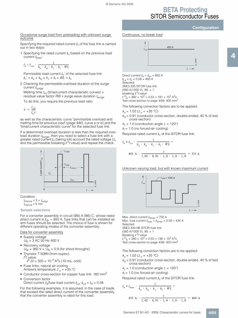
BETA ProtectingSITOR Semiconductor Fuses
Configuration
4/65Siemens ET B1 AO · 2009, Characteristic curves for fuses
4
Occasional surge load from preloading with unknown surge outcome
Specifying the required rated current In of the fuse link is carried out in two steps:
1. Specifying the rated current In based on the previous load current Iprev:
Permissible load current In' of the selected fuse link: In’ = ku × kq × kl × kl × WL × In
2. Checking the permissible overload duration of the surge current IsurgeMelting time tvs (time/current characteristic curves) × residual value factor RW ‡ surge wave duration tsurge
To do this, you require the previous load ratio
as well as the characteristic curve "permissible overload and melting time for previous load" (page 4/60, curve a or b) and the "time/current characteristic curve" for the selected fuse link.
If a determined overload duration is less than the required over-load duration tsurge, then you need to select a fuse link with a greater rated current In (taking into account the rated voltage Un and the permissible breaking I 2t value) and repeat the check.
Condition:tinterval ‡ 3 × tsurge tinterval ‡ 5 min
Sample selections
For a converter assembly in circuit (B6) A (B6) C, whose rated direct current is Idn = 850 A, fuse links that can be installed as arm fuses should be selected. The choice of fuse is shown for different operating modes of the converter assembly.
Data for converter assembly• Supply voltage
UN = 3 AC 50 Hz 400 V• Recovery voltage
UW = 360 V = UN × 0.9 (for shoot-throughs) • Thyristor T 508N (from eupec), l2t value
I2 dt = 320 × 10 3 A2s (10 ms, cold) • Fuse links, natural air cooling
Ambient temperature Ju = +35 °C • Conductor cross-section for copper fuse link: 160 mm2 • Conversion factor
Direct current Id/fuse load current ILa: ILa = Id × 0.58
For the following examples, it is assumed, in the case of loads that exceed the rated direct current of the converter assembly, that the converter assembly is rated for this load.
Continuous, no-break load
Direct current Id = Idn = 850 A ILa = Id × 0.58 = 493 A Selected: 3NE3 335 SITOR fuse link (560 A/1000 V), WL = 1 breaking I 2t valueI 2ta = 360 × 103 × 0.53 = 191 × 103 A2s Test cross-section to page 4/56: 400 mm2
The following correction factors are to be applied:ku = 1.02 (Ju = +35 °C)kq = 0.91 (conductor cross-section, double-ended, 40 % of test
cross-section)kl = 1.0 (conduction angle l = 120°)kl = 1.0 (no forced-air cooling)
Required rated current In of the SITOR fuse link:
Unknown varying load, but with known maximum current
Max. direct current Idmax = 750 A Max. fuse current Imax = Idmax × 0.58 = 435 A Selected: 3NE3 334-0B SITOR fuse link (560 A/1000 V), WL = 1 Breaking I 2t valueI 2ta = 260 × 103 × 0.53 = 138 × 103 A2s Test cross-section to page 4/56: 400 mm2
The following correction factors are to be applied: ku = 1.02 (Ju = +35 °C)kq = 0.91 (conductor cross-section, double-ended, 40 % of test
cross-section)kl = 1.0 (conduction angle l = 120°)kl = 1.0 (no forced-air cooling)
Required rated current In of the SITOR fuse link:
In Ivor1
ku kq kl kl WL····---------------------------------------------------------·>
VIeff
In¢-------=
�
'
�
�
0
I2_1
2652
�
La
prev
interval
surge
surge
Load
cur
rent
�
������
� � � � �
� �
In ILa1
ku kq· kl· kl WL··------------------------------------------------------· 493 A=‡
493 A 11 02, 0 91,· 1 0,· 1 0, 1 0,··--------------------------------------------------------------------------· 531 A=
- � ,
�
������
4 � � � � � �
� �
In Imax1
ku kq· kl· kl WL··------------------------------------------------------· 493 A=‡
435 A 11 02, 0 91,· 1 0,· 1 0, 1 0,··--------------------------------------------------------------------------· 469 A=
ET_B1_AO_Kennlinien.book Seite 65 Dienstag, 13. Oktober 2009 11:58 11
© Siemens AG 2009

BETA ProtectingSITOR Semiconductor Fuses
Configuration
4/66 Siemens ET B1 AO · 2009, Characteristic curves for fuses
4
Varying load with load cycle
Direct current: Id1 =1200 A t1 = 20 s Id2 = 500 A t2 = 240 s Id3 =1000 A t3 = 10 s Id4 = 0 A t4 = 60 s
Fuse current: ILa1 =1200 × 0.58 = 696 A ILa2 = 500 × 0.58 = 290 A ILa3 =1000 × 0.58 = 580 A
R.m.s. value of load current
Selected: 3NE3 333 SITOR fuse link (450 A/1000 V), WL = 1 Breaking I2t value I2ta = 175 × 103 × 0.53 = 93 × 103 A2s Test cross-section to page 4/56: 320 mm2
The following correction factors are to be applied:ku = 1.02 (Ju = +35 °C)kq = 0.94 (conductor cross-section, double-ended, 50 % of test
cross-section)kl = 1.0 (conduction angle l = 120°)kl = 1.0 (no forced-air cooling).
1. Required rated current In of the SITOR fuse link:
Permissible load current In’ of the selected fuse link:
In’ = ku × kq × kl × kl × WL × In = 1.02 × 0.94 × 1.0 × 1.0 × 1.0 × 450 = 431 A
2. Checking the permissible overload duration of current blocks exceeding the permissible fuse current In’.
Previous load ratio:
Residual value factor RW: for V = 0.74 of curve a (characteris-tic curve page 4/60, frequent surge/load cycle currents) RW = 0.2
Current block ILa1: melting time tvs: 230 s (from time/current characteristic curve for 3NE3 333) tvs × RW = 230 s × 0.2 = 46 s > t1Current block ILa3: melting time tvs: 1200 s (from time/current characteristic curve for 3NE3 333) tvs × RW = 1200 s × 0,2 = 240 s > t3
Occasional surge load from preloading with unknown surge outcome
Direct current: Idprev = 700 A Idsurge = 500 A tsurge = 8 s
Fuse current: Iprev = Idprev × 0.58 = 406 A Isurge = Idprev × 0.58 = 1015 A
Conditions tinterval ‡ 3 tsurge und tinterval ‡ 5 min must be fulfilled.
Selected: 3NE3 333 SITOR fuse link(560 A/1000 V), WL = 1 Breaking I2t value I2ta = 360 × 103 × 0.53 = 191 × 103 A2s Test cross-section to page 4/56: 400 mm2
The following correction factors are to be applied:
ku = 1.02 (Ju = +35 °C)kq = 0.91 (conductor cross-section, double-ended, 40 % of test
cross-section)
kl = 1.0 (conduction angle l = 120°)
kl = 1.0 (no forced-air cooling)
1. Required rated current In of the SITOR fuse link:
Permissible load current In’ of the selected fuse link:
In’ =ku × kq × kl × kl × WL × In = 1.02 × 0.91 × 1.0 × 1.0 × 1.0 × 560 = 520 A
2. Checking the permissible overload duration of the surge current Isurge
Previous load ratio:
Residual value factor RW: for V = 0.78 of curve a (characteris-tic curve page 4/60, frequent surge/load cycle currents) RW = 0.18 Surge current Isurge: melting time tvs: 110 s (from time/current characteristic curve for 3NE3 333) tvs × RW = 110 s × 0.18 = 19.8 s > tsurge Correction factors can be found on page 4/56 and page 4/57.
� �
�
� � �
5�
�
� � ��
4 � � � � � �
4 � � � � � � � � � 4 � � � � � �
4 � � � �
��
� � � 4 � � � � � �
�
������
� �
Ieff6962 20 2902+· 240 5802 10·+·
330------------------------------------------------------------------------------------ 317A= =
In IEff1
ku kq· kl· kl WL··------------------------------------------------------· 493 A=‡
317 A 11 02, 0 94,· 1 0,· 1 0, 1 0,··--------------------------------------------------------------------------· 331 A=
VIeff
In¢------- 317
431-------- 0 74,= = =
�
�
4 � � � � � �
4 � � � � �
4 � � � �
������
� �
prev
surge
surge
In Ivor1
ku kq· kl· kl WL··------------------------------------------------------· 493 A=‡
406 A 11 02, 0 91,· 1 0,· 1 0, 1 0,··--------------------------------------------------------------------------· 437 A=
VIvor
In¢------- 406
520-------- 0 78,= = =
ET_B1_AO_Kennlinien.book Seite 66 Dienstag, 13. Oktober 2009 11:58 11
© Siemens AG 2009

BETA ProtectingSITOR Semiconductor Fuses
Notes
4/67Siemens ET B1 AO · 2009, Characteristic curves for fuses
4
ET_B1_AO_Kennlinien.book Seite 67 Dienstag, 13. Oktober 2009 11:58 11
© Siemens AG 2009

BETA ProtectingSITOR Semiconductor Fuses
Notes
4/68 Siemens ET B1 AO · 2009, Characteristic curves for fuses
4
ET_B1_AO_Kennlinien.book Seite 68 Dienstag, 13. Oktober 2009 11:58 11
© Siemens AG 2009

BETA ProtectingSITOR Semiconductor Fuses
Notes
4/69Siemens ET B1 AO · 2009, Characteristic curves for fuses
4
ET_B1_AO_Kennlinien.book Seite 69 Dienstag, 13. Oktober 2009 11:58 11
© Siemens AG 2009
BETA ProtectingSITOR Semiconductor Fuses
Notes
4/70 Siemens ET B1 AO · 2009, Characteristic curves for fuses
4
7
ET_B1_AO_Kennlinien.book Seite 70 Dienstag, 13. Oktober 2009 11:58 11
© Siemens AG 2009

CatalogsIndustry Automation, Drive Technologies and Low Voltage Distribution
Further information can be obtained from our branch offices listedin the appendix or at www.siemens.com/automation/partner
IA DT LV/3U/En 05.10.09
Interactive Catalog on DVD Catalogfor Industry Automation, Drive Technologies and Low Voltage Distribution
CA 01
Drive SystemsVariable-Speed Drives
SINAMICS G110, SINAMICS G120 Standard Inverters SINAMICS G110D, SINAMICS G120D Distributed Inverters
D 11.1
SINAMICS G130 Drive Converter Chassis Units SINAMICS G150 Drive Converter Cabinet Units
D 11
SINAMICS GM150, SINAMICS SM150 Medium-Voltage Converters
D 12
SINAMICS S120 Chassis Format Units and Cabinet Modules SINAMICS S150 Converter Cabinet Units
D 21.3
Three-phase Induction Motors D 84.1
• H-compact• H-compact PLUS
Asynchronous Motors Standardline D 86.1
Synchronous Motors with Permanent-Magnet Technology, HT-direct
D 86.2
DC Motors DA 12
SIMOREG DC MASTER 6RA70 Digital Chassis Converters
DA 21.1
SIMOREG K 6RA22 Analog Chassis Converters DA 21.2
PDF: SIMOREG DC MASTER 6RM70 Digital Converter Cabinet Units
DA 22
SIMOVERT PM Modular Converter Systems DA 45
SIEMOSYN Motors DA 48
MICROMASTER 420/430/440 Inverters DA 51.2
MICROMASTER 411/COMBIMASTER 411 DA 51.3
SIMOVERT MASTERDRIVES Vector Control DA 65.10
SIMOVERT MASTERDRIVES Motion Control DA 65.11
Synchronous and asynchronous servomotors for SIMOVERT MASTERDRIVES
DA 65.3
SIMODRIVE 611 universal and POSMO DA 65.4
SIMOTION, SINAMICS S120 and Motors for Production Machines
PM 21
SINAMICS S110 The Basic Positioning Drive
PM 22
Low-Voltage Three-Phase-Motors
IEC Squirrel-Cage Motors D 81.1
MOTOX Geared Motors D 87.1
Automation Systems for Machine Tools SIMODRIVE NC 60
• Motors• Converter Systems SIMODRIVE 611/POSMO
Automation Systems for Machine Tools SINAMICS NC 61
• Motors• Drive System SINAMICS S120
Drive and Control Components for Hoisting Equipment HE 1
Mechanical Driving Machines
Flender Standard Couplings MD 10.1
Electrical Installation TechnologyPDF: ALPHA Distribution Boards and Terminal Blocks ET A1
PDF: ALPHA 8HP Molded-Plastic Distribution System ET A3
PDF: BETA Low-Voltage Circuit Protection ET B1
PDF: DELTA Switches and Socket Outlets ET D1
PDF: GAMMA Building Management Systems ET G1
PDF: These catalogs are only available as pdf files.
Motion Control Catalog
SINUMERIK & SIMODRIVE Automation Systems for Machine Tools
NC 60
SINUMERIK & SINAMICS Automation Systems for Machine Tools
NC 61
SIMOTION, SINAMICS S120 and Motors for Production Machines
PM 21
SINAMICS S110 The Basic Positioning Drive
PM 22
Low-VoltageControls and Distribution – SIRIUS, SENTRON, SIVACON
LV 1
Controls and Distribution – Technical InformationSIRIUS, SENTRON, SIVACON
LV 1 T
SICUBE System Cubicles and Cubicle Air-Conditioning LV 50
SIDAC Reactors and Filters LV 60
SIVACON 8PS Busbar Trunking Systems LV 70
Power Supply and System CablingPower supplies SITOP power and LOGO! Power KT 10.1
System cabling SIMATIC TOP connect KT 10.2
Process Instrumentation and AnalyticsField Instruments for Process Automation FI 01
PDF: Indicators for panel mounting MP 12
SIREC Recorders and Accessories MP 20
SIPART, Controllers and Software MP 31
PDF: Products for Weighing Technology WT 10
Process Analytical Instruments PA 01
PDF: Process Analytics, Components for the System Integration
PA 11
SIMATIC HMIHuman Machine Interface Systems ST 80
SIMATIC Industrial Automation SystemsProducts for Totally Integrated Automation and Micro Automation
ST 70
SIMATIC PCS 7 Process Control System ST PCS 7
Add-ons for the SIMATIC PCS 7 Process Control System
ST PCS 7.1
Migration solutions with the SIMATIC PCS 7 Process Control System
ST PCS 7.2
pc-based Automation ST PC
SIMATIC Control Systems ST DA
SIMATIC NETIndustrial Communication IK PI
SIMATIC SensorsSensors for Factory Automation FS 10
System SolutionsApplications and Products for Industry are part of the interactive catalog CA 01
TELEPERM M Process Control SystemPDF: AS 488/TM automation systems PLT 112
U3en_4f.fm Seite 2 Montag, 5. Oktober 2009 3:50 15
© Siemens AG 2009
www.siemens.com/e-installation
Siemens AGIndustry SectorBuilding Technologies DivisionPostfach 10 09 5393009 REGENSBURGGERMANY
www.siemens.com/betawww.siemens.com/buildingtechnologies
Subject to change without prior noticePDF only: (E86060-K8220-A121-A2-7600)3P.8103.61.02KG 1009 112 En © Siemens AG 2009
The information provided in this catalog contains descriptions or characteristics of performance which in case of actual use do not always apply as described or which may change as a result of further development of the products. An obligation to provide the respective characteristics shall only exist if expressly agreed in the terms of contract. Availability and technical specifications are subject to change without notice.All product designations may be trademarks or product names of Siemens AG or supplier companies whose use by third parties for their own purposes could violate the rights of the owners.
et_b1_ao_kennlinien_umschlag_2001 1et_b1_ao_kennlinien_umschlag_2001 1 22.10.2009 09:42:5022.10.2009 09:42:50
© Siemens AG 2009

Cat
alo
g A
dd
-On
ET
B1
AO
· 2
00
9B
ETA
Low
-Vo
ltag
e C
ircu
it P
rote
ctio
n
et_b1_ao_kennlinien_umschlag_2002 2et_b1_ao_kennlinien_umschlag_2002 2 22.10.2009 09:42:5222.10.2009 09:42:52
© Siemens AG 2009