bioreactors for tissue engineering - unipi.itbioreactors for tissue engineering ... same cell types...
TRANSCRIPT
Bioreactors for
Tissue Engineering
Lesson 5 – 15/12/2015
Serena Giusti
PSWD for zip files: Bioreactors2014
Connected Cell Culture
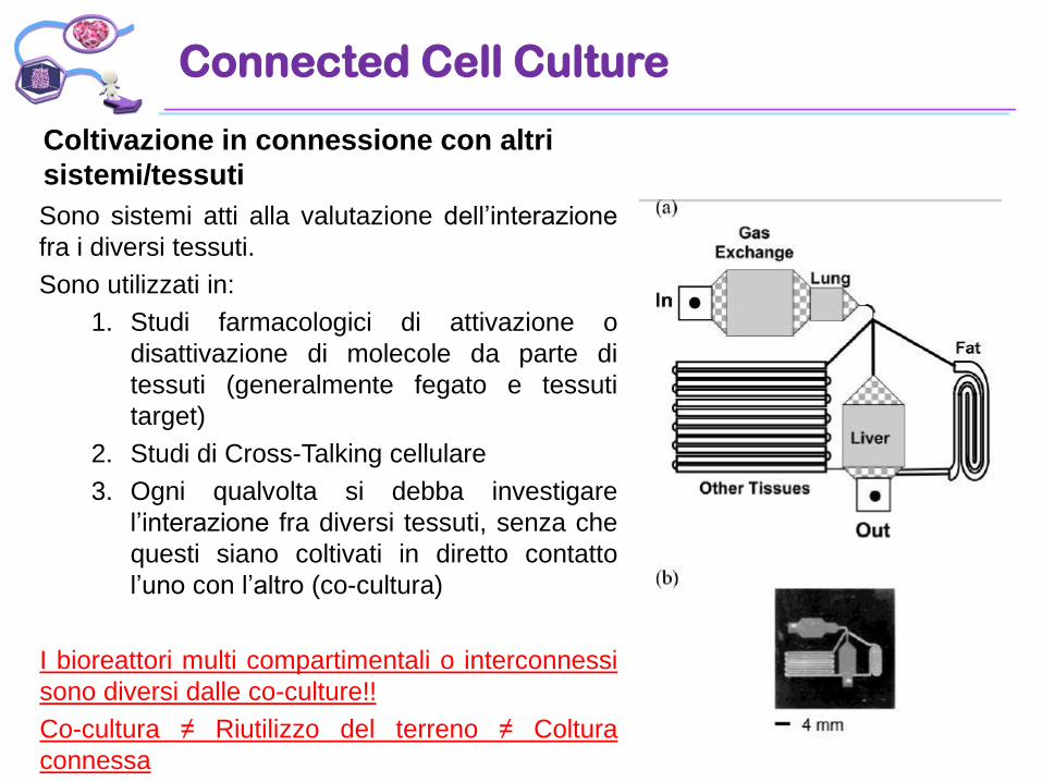
Coltivazione in connessione con altri
sistemi/tessuti
Sono sistemi atti alla valutazione dell’interazione
fra i diversi tessuti.
Sono utilizzati in:
1. Studi farmacologici di attivazione o
disattivazione di molecole da parte di
tessuti (generalmente fegato e tessuti
target)
2. Studi di Cross-Talking cellulare
3. Ogni qualvolta si debba investigare
l’interazione fra diversi tessuti, senza che
questi siano coltivati in diretto contatto
l’uno con l’altro (co-cultura)
I bioreattori multi compartimentali o interconnessi
sono diversi dalle co-culture!!
Co-cultura ≠ Riutilizzo del terreno ≠ Coltura
connessa
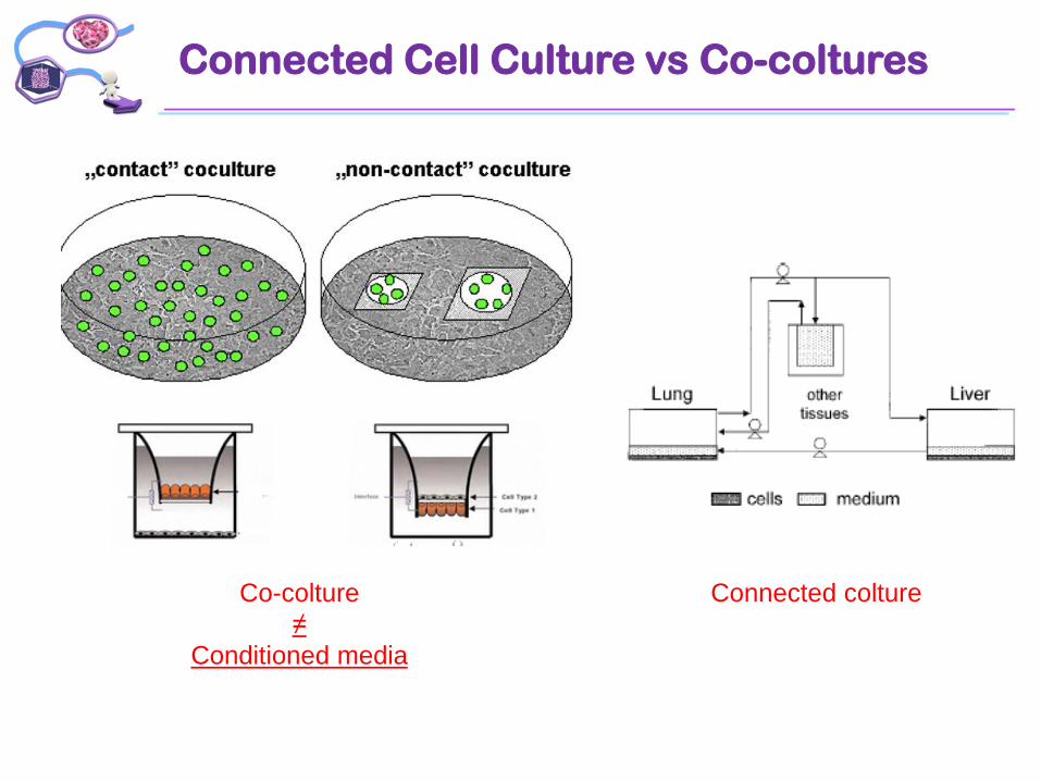
Connected Cell Culture vs Co-coltures
Co-colture
≠
Conditioned media
Connected colture
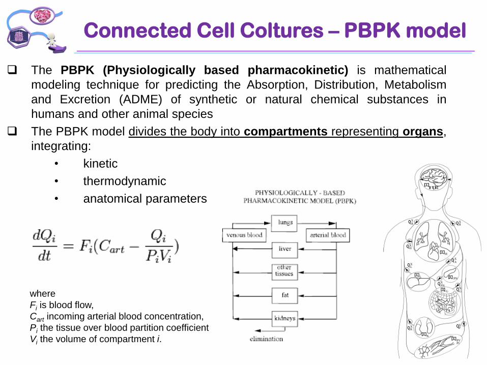
Connected Cell Coltures – PBPK model
The PBPK (Physiologically based pharmacokinetic) is mathematical
modeling technique for predicting the Absorption, Distribution, Metabolism
and Excretion (ADME) of synthetic or natural chemical substances in
humans and other animal species
The PBPK model divides the body into compartments representing organs,
integrating:
• kinetic
• thermodynamic
• anatomical parameters
where
Fi is blood flow,
Cart incoming arterial blood concentration,
Pi the tissue over blood partition coefficient
Vi the volume of compartment i.
Connected Cell Coltures – PBPK model
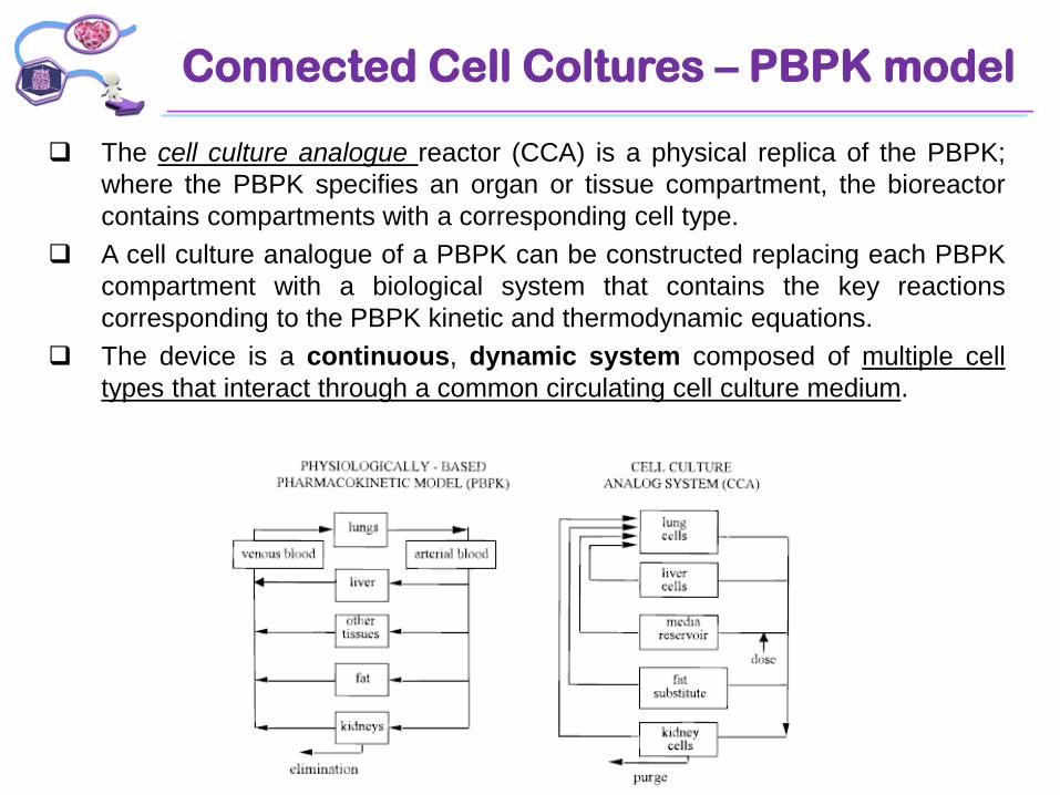
The cell culture analogue reactor (CCA) is a physical replica of the PBPK;
where the PBPK specifies an organ or tissue compartment, the bioreactor
contains compartments with a corresponding cell type.
A cell culture analogue of a PBPK can be constructed replacing each PBPK
compartment with a biological system that contains the key reactions
corresponding to the PBPK kinetic and thermodynamic equations.
The device is a continuous, dynamic system composed of multiple cell
types that interact through a common circulating cell culture medium.
Case study: naphthalene
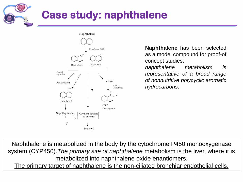
Naphthalene has been selected
as a model compound for proof-of
concept studies:
naphthalene metabolism is
representative of a broad range
of nonnutritive polycyclic aromatic
hydrocarbons.
Naphthalene is metabolized in the body by the cytochrome P450 monooxygenase
system (CYP450).The primary site of naphthalene metabolism is the liver, where it is
metabolized into naphthalene oxide enantiomers.
The primary target of naphthalene is the non-ciliated bronchiar endothelial cells.
Key points
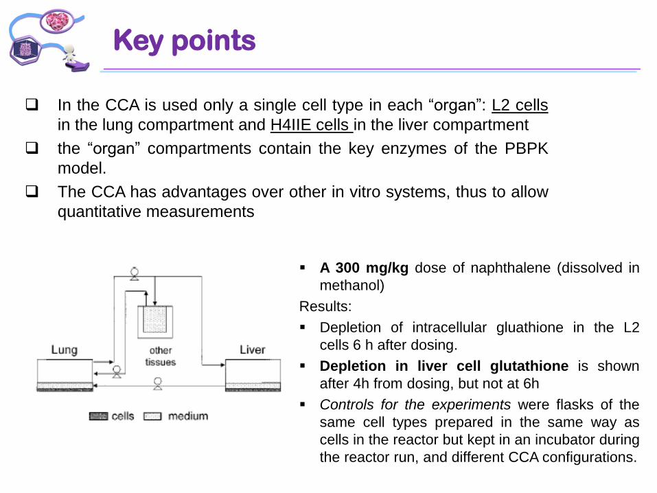
In the CCA is used only a single cell type in each “organ”: L2 cells
in the lung compartment and H4IIE cells in the liver compartment
the “organ” compartments contain the key enzymes of the PBPK
model.
The CCA has advantages over other in vitro systems, thus to allow
quantitative measurements
A 300 mg/kg dose of naphthalene (dissolved in
methanol)
Results:
Depletion of intracellular gluathione in the L2
cells 6 h after dosing.
Depletion in liver cell glutathione is shown
after 4h from dosing, but not at 6h
Controls for the experiments were flasks of the
same cell types prepared in the same way as
cells in the reactor but kept in an incubator during
the reactor run, and different CCA configurations.
The «micro» CCA-PBPK
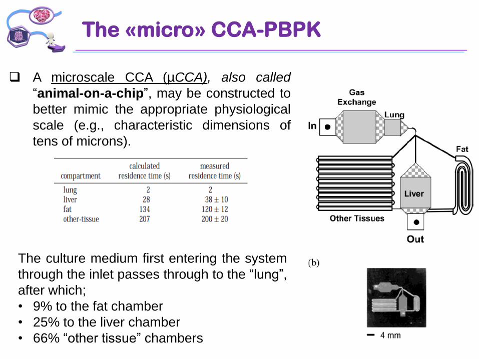
A microscale CCA (µCCA), also called
“animal-on-a-chip”, may be constructed to
better mimic the appropriate physiological
scale (e.g., characteristic dimensions of
tens of microns).
The culture medium first entering the system
through the inlet passes through to the “lung”,
after which;
• 9% to the fat chamber
• 25% to the liver chamber
• 66% “other tissue” chambers
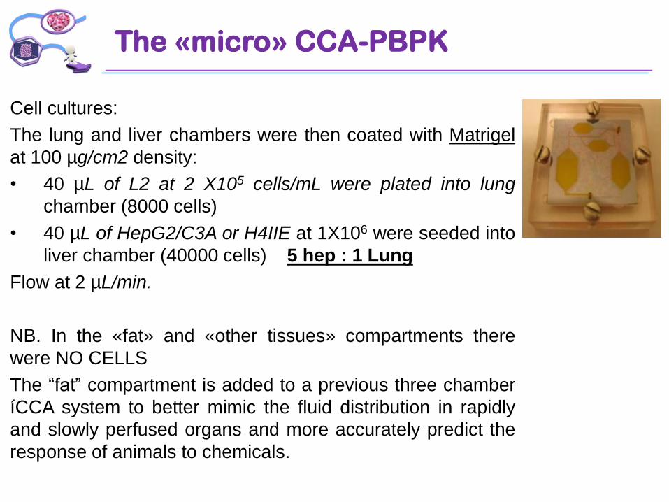
Cell cultures:
The lung and liver chambers were then coated with Matrigel
at 100 µg/cm2 density:
• 40 µL of L2 at 2 X10⁵ cells/mL were plated into lung
chamber (8000 cells)
• 40 µL of HepG2/C3A or H4IIE at 1X10⁶ were seeded into
liver chamber (40000 cells) 5 hep : 1 Lung
Flow at 2 µL/min.
NB. In the «fat» and «other tissues» compartments there
were NO CELLS
The “fat” compartment is added to a previous three chamber
íCCA system to better mimic the fluid distribution in rapidly
and slowly perfused organs and more accurately predict the
response of animals to chemicals.
The «micro» CCA-PBPK
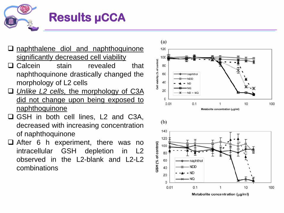
Results µCCA
naphthalene diol and naphthoquinone
significantly decreased cell viability
Calcein stain revealed that
naphthoquinone drastically changed the
morphology of L2 cells
Unlike L2 cells, the morphology of C3A
did not change upon being exposed to
naphthoquinone
GSH in both cell lines, L2 and C3A,
decreased with increasing concentration
of naphthoquinone
After 6 h experiment, there was no
intracellular GSH depletion in L2
observed in the L2-blank and L2-L2
combinations
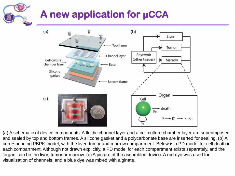
A new application for µCCA
(a) A schematic of device components. A fluidic channel layer and a cell culture chamber layer are superimposed
and sealed by top and bottom frames. A silicone gasket and a polycarbonate base are inserted for sealing. (b) A
corresponding PBPK model, with the liver, tumor and marrow compartment. Below is a PD model for cell death in
each compartment. Although not drawn explicitly, a PD model for each compartment exists separately, and the
‘organ’ can be the liver, tumor or marrow. (c) A picture of the assembled device. A red dye was used for
visualization of channels, and a blue dye was mixed with alginate.

Although microfluidic systems have a great
potential in enhancing the drug
development process, actual applications
of microfluidic systems in medical or life
science area have been limited.
• current microfluidic devices require
specialized skills for fabrication and
operation, which makes it difficult to be
used by non-experts.
• microfluidic cell cultures need more
indepth study, such as maintenance of
sterility, formation of air bubbles, the
effect of shear stress on cells, and the
«edge-effect»
The use of gravity-induced flow eliminates
the need for a pump, and prevents
formation of air bubbles.
A new application for µCCA
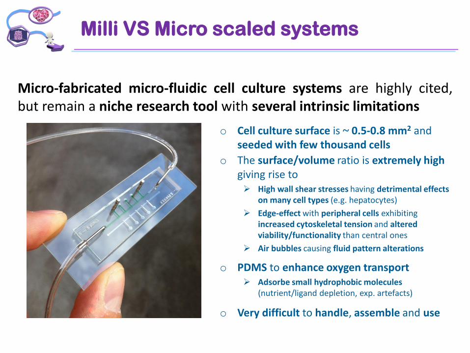
Milli VS Micro scaled systems
Micro-fabricated micro-fluidic cell culture systems are highly cited,but remain a niche research tool with several intrinsic limitations
o Cell culture surface is ~ 0.5-0.8 mm2 and seeded with few thousand cells
o The surface/volume ratio is extremely high giving rise to High wall shear stresses having detrimental effects
on many cell types (e.g. hepatocytes)
Edge-effect with peripheral cells exhibiting increased cytoskeletal tension and altered viability/functionality than central ones
Air bubbles causing fluid pattern alterations
o PDMS to enhance oxygen transport Adsorbe small hydrophobic molecules
(nutrient/ligand depletion, exp. artefacts)
o Very difficult to handle, assemble and use
Milli VS Micro scaled systems
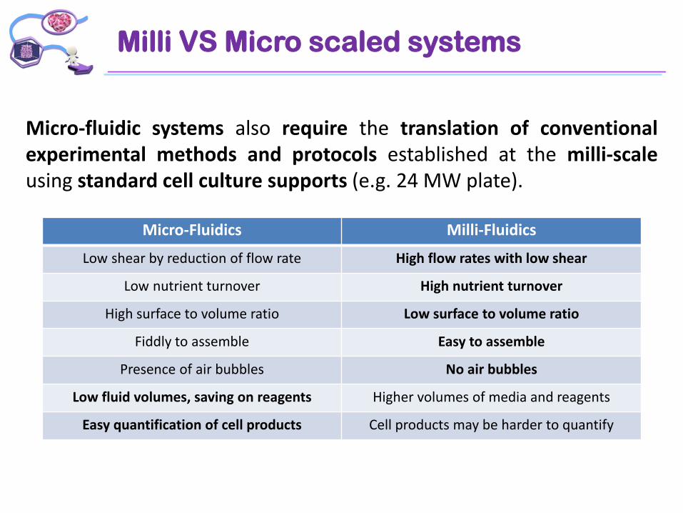
Micro-fluidic systems also require the translation of conventionalexperimental methods and protocols established at the milli-scaleusing standard cell culture supports (e.g. 24 MW plate).
Micro-Fluidics Milli-Fluidics
Low shear by reduction of flow rate High flow rates with low shear
Low nutrient turnover High nutrient turnover
High surface to volume ratio Low surface to volume ratio
Fiddly to assemble Easy to assemble
Presence of air bubbles No air bubbles
Low fluid volumes, saving on reagents Higher volumes of media and reagents
Easy quantification of cell products Cell products may be harder to quantify
Milli VS Micro scaled systems
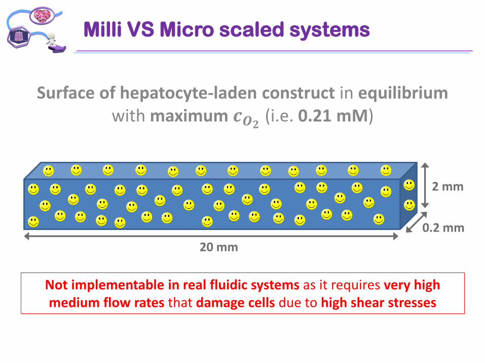
Surface of hepatocyte-laden construct in equilibriumwith maximum 𝒄𝑶𝟐 (i.e. 0.21 mM)
Not implementable in real fluidic systems as it requires very high medium flow rates that damage cells due to high shear stresses
2 mm
0.2 mm
20 mm
Milli VS Micro scaled systems
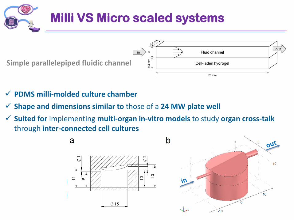
Simple parallelepiped fluidic channel
Micro-fluidic --> h = 0.2 mm
Milli-fluidic --> h = 2 mm
PDMS milli-molded culture chamber
Shape and dimensions similar to those of a 24 MW plate well
Suited for implementing multi-organ in-vitro models to study organ cross-talk through inter-connected cell cultures
Milli VS Micro scaled systems
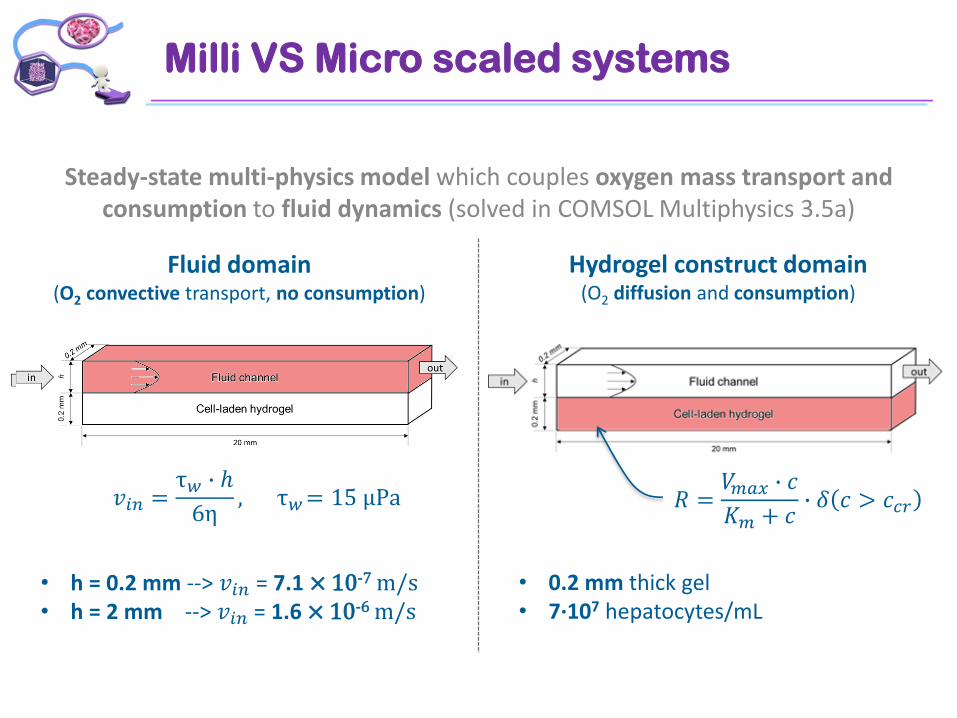
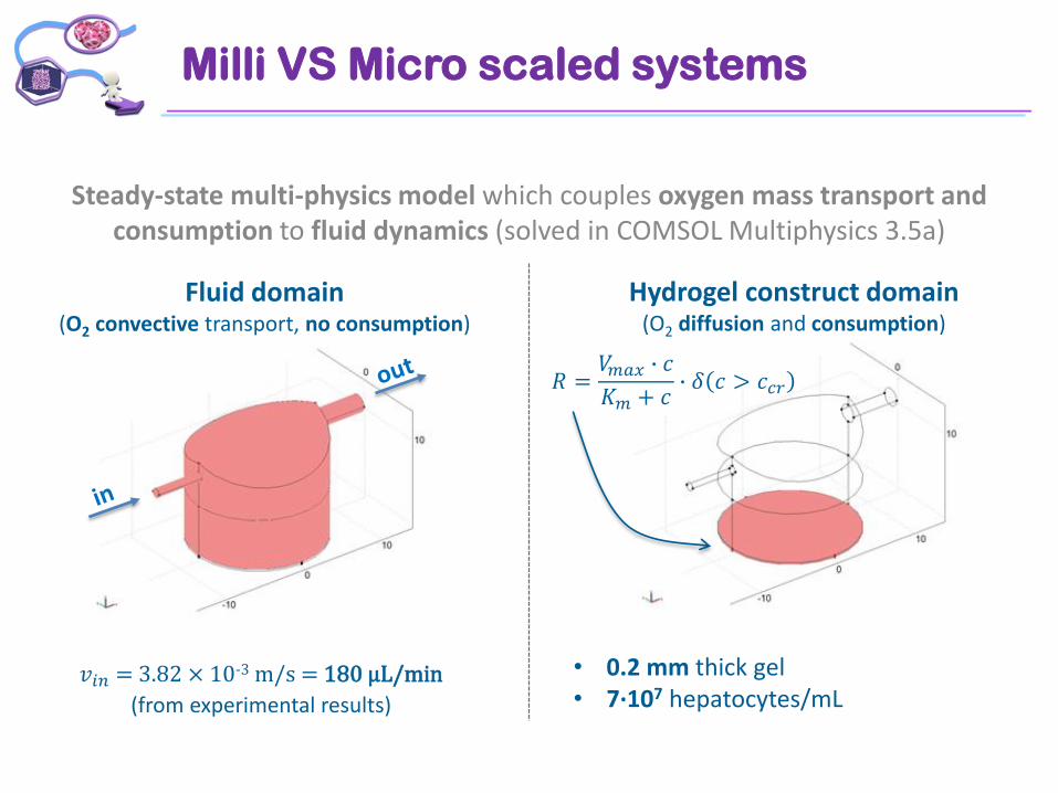
Steady-state multi-physics model which couples oxygen mass transport and consumption to fluid dynamics (solved in COMSOL Multiphysics 3.5a)
Fluid domain(O2 convective transport, no consumption)
Hydrogel construct domain(O2 diffusion and consumption)
𝑅 =𝑉𝑚𝑎𝑥 ∙ 𝑐
𝐾𝑚 + 𝑐∙ 𝛿 𝑐 > 𝑐𝑐𝑟
• 0.2 mm thick gel• 7∙107 hepatocytes/mL
𝑣𝑖𝑛 =τ𝑤 ∙ ℎ
6η, τ𝑤= 15 μPa
• h = 0.2 mm --> 𝑣𝑖𝑛 = 7.1 × 10⁻⁷ m/s• h = 2 mm --> 𝑣𝑖𝑛 = 1.6 × 10⁻⁶ m/s
Milli VS Micro scaled systems
Steady-state multi-physics model which couples oxygen mass transport and consumption to fluid dynamics (solved in COMSOL Multiphysics 3.5a)
Fluid domain(O2 convective transport, no consumption)
Hydrogel construct domain(O2 diffusion and consumption)
𝑅 =𝑉𝑚𝑎𝑥 ∙ 𝑐
𝐾𝑚 + 𝑐∙ 𝛿 𝑐 > 𝑐𝑐𝑟
𝑣𝑖𝑛 = 3.82 × 10⁻³ m/s = 180 µL/min
(from experimental results)
• 0.2 mm thick gel• 7∙107 hepatocytes/mL
Milli VS Micro scaled systems
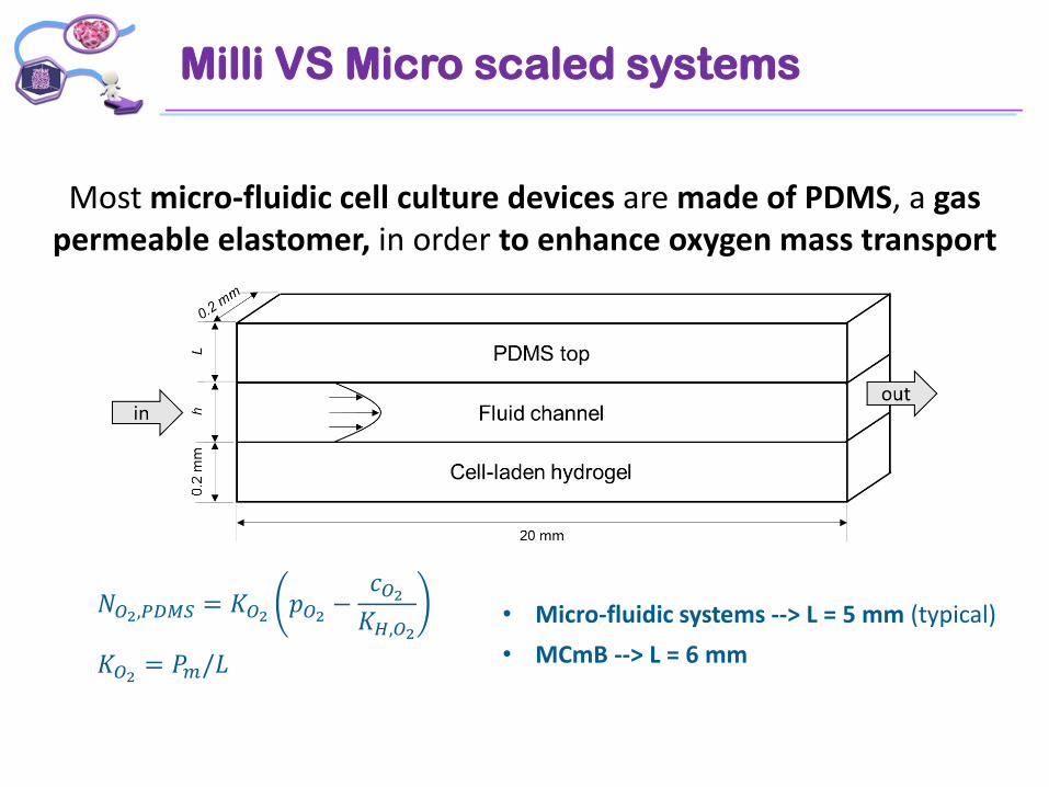
Most micro-fluidic cell culture devices are made of PDMS, a gas permeable elastomer, in order to enhance oxygen mass transport
𝑁𝑂2,𝑃𝐷𝑀𝑆 = 𝐾𝑂2 𝑝𝑂2 −𝑐𝑂2𝐾𝐻,𝑂2
𝐾𝑂2 = 𝑃𝑚/𝐿
• Micro-fluidic systems --> L = 5 mm (typical)
• MCmB --> L = 6 mm

Milli VS Micro scaled systems
Milli VS Micro scaled systems
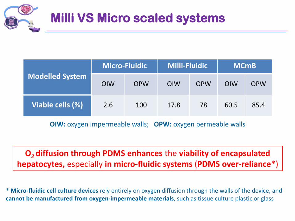
Modelled System
Micro-Fluidic Milli-Fluidic MCmB
OIW OPW OIW OPW OIW OPW
Viable cells (%) 2.6 100 17.8 78 60.5 85.4
OIW: oxygen impermeable walls; OPW: oxygen permeable walls
O2 diffusion through PDMS enhances the viability of encapsulated hepatocytes, especially in micro-fluidic systems (PDMS over-reliance*)
* Micro-fluidic cell culture devices rely entirely on oxygen diffusion through the walls of the device, and cannot be manufactured from oxygen-impermeable materials, such as tissue culture plastic or glass
Milli VS Micro scaled systems
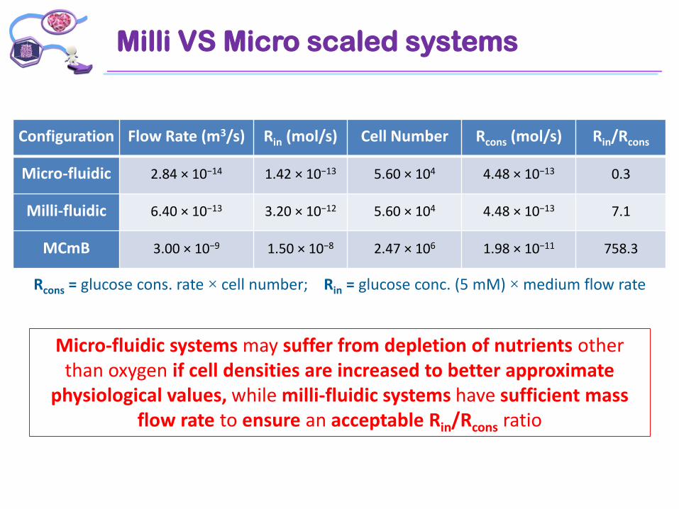
Configuration Flow Rate (m3/s) Rin (mol/s) Cell Number Rcons (mol/s) Rin/Rcons
Micro-fluidic 2.84 × 10⁻¹⁴ 1.42 × 10⁻¹³ 5.60 × 10⁴ 4.48 × 10⁻¹³ 0.3
Milli-fluidic 6.40 × 10⁻¹³ 3.20 × 10⁻¹² 5.60 × 10⁴ 4.48 × 10⁻¹³ 7.1
MCmB 3.00 × 10⁻⁹ 1.50 × 10⁻⁸ 2.47 × 10⁶ 1.98 × 10⁻¹¹ 758.3
Rcons = glucose cons. rate × cell number; Rin = glucose conc. (5 mM) × medium flow rate
Micro-fluidic systems may suffer from depletion of nutrients other than oxygen if cell densities are increased to better approximate
physiological values, while milli-fluidic systems have sufficient mass flow rate to ensure an acceptable Rin/Rcons ratio
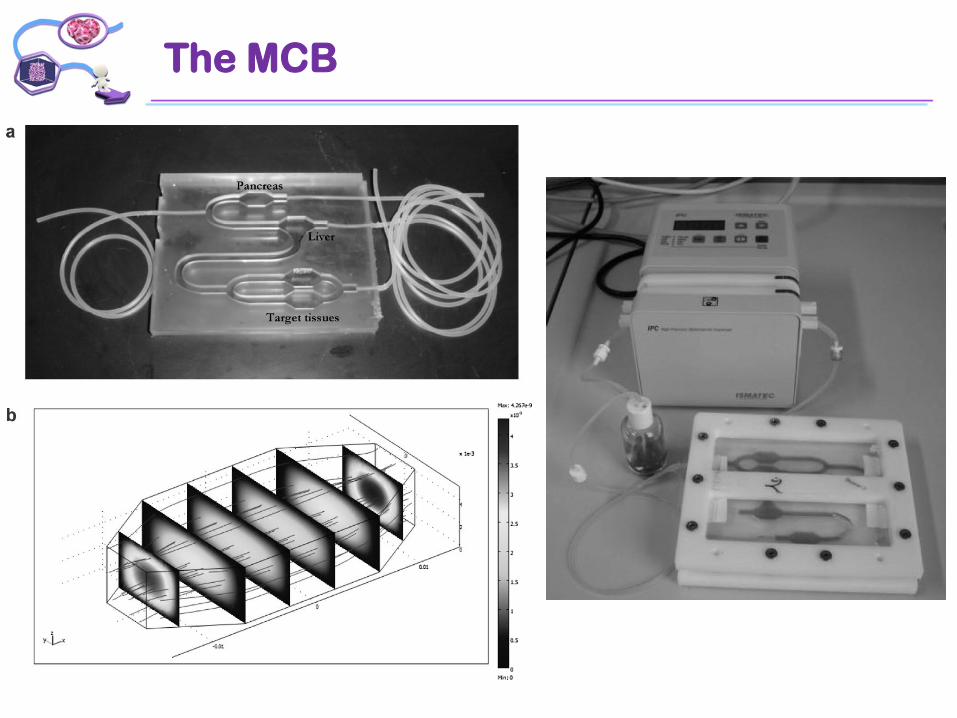
The MCB
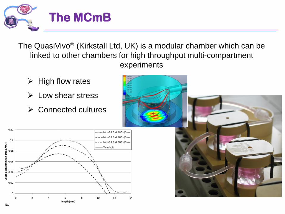
The MCmB
The QuasiVivo (Kirkstall Ltd, UK) is a modular chamber which can be
linked to other chambers for high throughput multi-compartment
experiments
High flow rates
Low shear stress
Connected cultures

Connected Cell Culture
Assays: TEER, Alamar, LDH, vWF, cytokines, albumin, ZO-1, etc
2 flow membrane bioreactorwith realtimeTEER
2 flow chambers
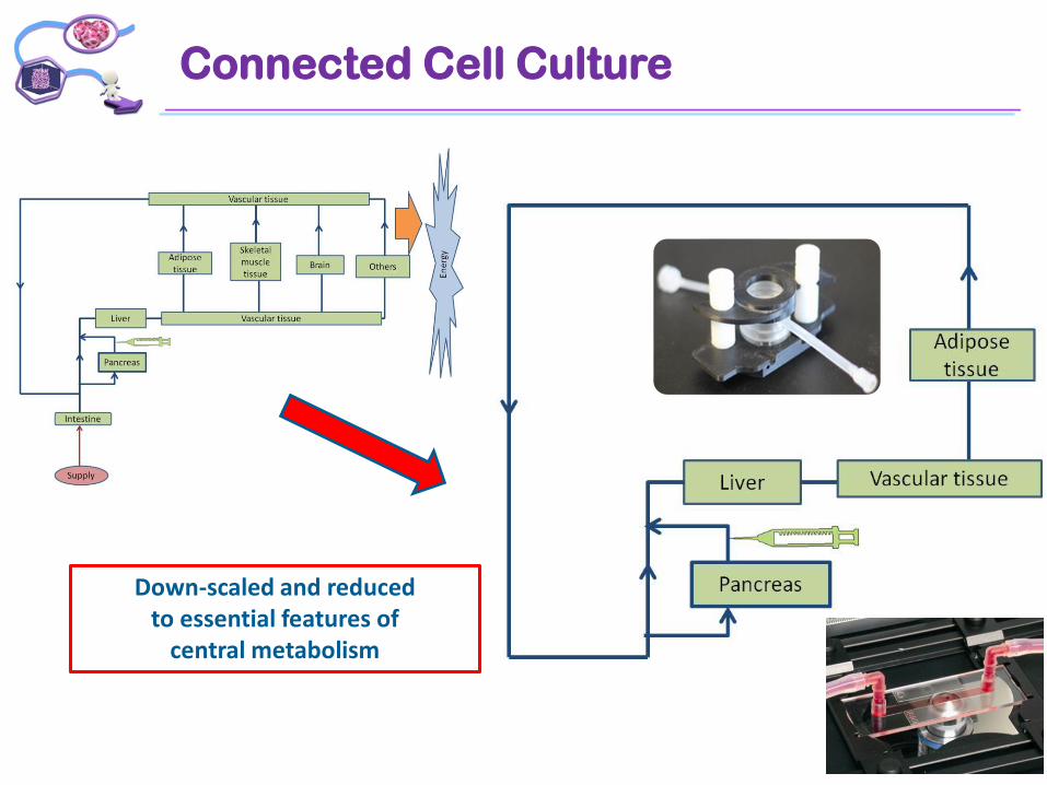
Connected Cell Culture
Down-scaled and reducedto essential features of
central metabolism