blomaterials science - dipartimento di scienze ... · blomaterials science an introductio tno...
TRANSCRIPT


BlOMATERIALS SCIENCEAn Introduction to
Materials in Medicine
Edited by
Buddy D. Ratner and Allan S. HoffmanCenter for Bioengineering and
Department of Chemical Engineering
University of Washington
Seattle, Washington
Frederick J. SchoenDepartment of Pathology
Brigham and Women's Hospital
and Harvard Medical School
Boston, Massachusetts
Jack E. LemonsDepartments of Biomaterials and Surgery
School of Dentistry and Medicine
University of Alabama at Birmingham
Birmingham, Alabama
Academic PressSan Diego London Boston New York Sydney Tokyo Toronto

Cover photographs: Background is detail of grains in cold-worked 316L stainlesssteel showing evidence of plastic deformation. (See Chapter 2.2, courtesy ofZimmer USA, Warsaw, IN.) Inset is cardiac pacemaker with polyurethane leadtine and connector. (See Chapter 6.2, courtesy of Medtronic, Inc.)
This book is printed on acid-free paper,
Copyright © 1996 by ACADEMIC PRESS
All Rights Reserved.No part of this publication may be reproduced or transmitted in any form or by anymeans, electronic or mechanical, including photocopy, recording, or any informationstorage and retrieval system, without permission in writing from the publisher.
Academic Pressa division of Harcourt Brace & Companv525 B Street, Suite 1900, San Diego, California 92101-4495, USAhttp://www.apnet.com
Academic Press Limited24-28 Oval Road, London NW1 7DX, UKhttp:/ /www.hbuk.co.uk/ap/
Library of Congress Cataloging-in-Publication Data
Biomaterials science : an introduction to materials in medicine /edited by Buddy D. Ratner ... [et al.].
p. cm.Includes index.ISBN 0-12-582460-2 (case: alk. paper)ISBN 0-12-582461-0 (paperback: alk. paper)1. Biomedical materials. I. Ratner, B. D. (Buddy D.). date.
R857.M3B5735 1996610'.28-dc20 96-19088
CIP
PRINTED IN THE UNITED STATES OF AMERICA01 02 EB 9 8 7 6 5

CONTENTS
Contributors ix 2.6 Ceramics, Glasses, and Glass-Ceramics 73Preface xi LARRY L. HENCH
Biomaterials Science.- An Interdisciplinary 2.7 Nafural Materjals 84
Endeavor IOANNIS v. YANNASBUDDY D. RATNER 1
2.8 Composites 94HAROLD ALEXANDER
PART IMATERIALS SCIENCE AND 2.9 Thin Films, Grafts, and Coatings 105
ENGINEERING BUDDY D. RATNER AND ALLAN S. HOFFMAN
CHAPTER 1 Properties of Materials 2.10 Fabrics 118SHALABY W. SHALABY
1.1 Introduction 11JACK E. LEMONS
2.11 Biologically Functional Materials 124ALLAN S. HOFFMAN
1.2 Bulk Properties of Materials 11FRANCIS W. COOKE
PART II1.3 Surface Properties of Materials 21 PART IIBUDDY D RATNER BIOLOGY, BIOCHEMISTRY,
CHAPTER 2 Classes of Materials Used in Medicine AND MEDICINE
2.1 Introduction 37 CHAPTERS Some Background ConceptsALLAN S. HOFFMAN
3.1 Introduction 133BUDDY D. RATNER
2.2 Metals 37JOHN B. BRUNSKI
3.2 Proteins: Structure, Properties, and Adsorption2.3 Polymers 50 to Surfaces 133
SUSAN A. V1SSER, ROBERT W. HERGENROTHER, THOMAS A. HORBETT
AND STUART L. COOPER
3.3 Cells: Their Surfaces and Interactions with2.4 Hydrogels 60 Materials 141
NIKOLAOS A. PF.PPAS JEFF M. SCHAKENRAAD
2.5 Bioresorbable and Bioerodible Materials 64 3.4 Tissues 147JOACHIM KOHN AND ROBERT LANGER FREDERICK J. SCHOEN
V

vi CONTENTS
CHAPTER 4 Host Reactions to Biomaterials andTheir Evaluation
4.1 Introduction 165FREDERICK .). SCHOEN
4.2 Inflammation, Wound Healing, and the ForeignBody Response 165JAMES M. ANDERSON
4.3 Immunology and the Complement System 173RICHARD J. JOHNSON
4.4 Systemic Toxicity and Hypersensitivity 188KATHARINE MERRITT
4.5 Blood Coagulation and Blood—MaterialsInteractions 193STEPHEN R. HANSON AND LAURENCE A. HARKER
4.6 Tumorigenesis and Biomaterials 200FREDERICK J. SCHOEN
4.7 implant-Associated Infection 205ANTHONY G. GRISTINA AND PAUL T. NAYLOR
CHAPTER 5 Testing Biomaterials
5.1 Introduction 215BUDDY D. RATNER
6.4 Mechanical Breakdown in the BiologicalEnvironment 267CARL R. McMILLIN
6.5 Pathologic Calcification of Biomaterials 272YASHWANT PATHAK, FREDERICK J. SCHOEN, AND ROBERT J. LEVY
CHAPTER 7 Application of Materials in Medicineand Dentistry
7.1 IntroductionJACK E. LEMONS
7.2 Cardiovascular ApplicationsPAUL DIDISHEIM AND JOHN T. WATSON
283
283
7.3 Nonthrombogenic Treatments and Strategies 297SUNG WAN KIM
7.4 Dental ImplantsJACK E. LEMONS
7.5 Adhesives and SealantsDENNIS C. SMITH
7.6 Ophthalmologic ApplicationsMIGUEL F. REFOJO
7.7 Orthopedic ApplicationsJ. LAWRENCE KATZ
308
319
328
335
5.2 In Vitro Assessment of Tissue CompatibilitySHARON I. NORTHUP
215 7.8 Drug Delivery SystemsJORGE HELLER
346
5.3 In Vivo Assessment of Tissue Compatibility 220MYRON SPECTOR AND PEGGY A. LALOR
5.4 Testing of Blood—Materials interactions 228STEPHEN HANSON AND BUDDY D. RATNER
5.5 Animal Models 238BRAD H. VALE, JOHN E. WILLSON, AND STEVEN M. NIEMI
CHAPTER 6 Degradation of Materials in theBiological Environment
6.1 Introduction 243BUDDY D. RATNER
6.2 Chemical and Biochemical Degradation ofPolymers 243ARTHUR J. COURY
6.3 Degradative Effects of the Biological Environmenton Metals and Ceramics 260DAVID F, WILLIAMS AND RACHEL L, WILLIAMS
7.9 SuturesDENNIS GOUPIL
356
7.10 Burn Dressings 360JEFFREY B. KANE, RONALD G. TOMPK1NS, MARTIN L. YARMUSH,
AND JOHN F. BURKE
7 . 1 1 BioelectrodesLOIS S. ROBBLEE AND JAMES D. SWEENEY
7.12 Biomedical Sensors and BiosensorsPAUL YAGER
CHAPTER 8 Artificial Organs
8.1 IntroductionFREDERICK J. SCHOEN
8.2 Implantable Pneumatic Artificial HeartsKEVIN D. MURRAY AND DON B. OLSEN
8.3 Extracorporeal Artificial OrgansPAUL S. MALCHESKY
371
375
389
389
400

CONTENTS vii
PACT III 9.7 Correlations of Material Surface Properties with
PRACTICAL ASPECTS Biological ResponsesOF B1OMATER1ALS
9.8 Implant Retrieval and Evaluation 451CHAPTER 9 Implants and Devices • JAMES M. ANDERSONCHAPTER 9 Implants and Devices
CHAPTER 10 New Products and Standards9.1 Introduction 415
FREDERICK J. SCHOEN 10.1 Introduction 457JACK E. LEMONS
9.2 Sterilization of Implants 415JOHN B. KOWALSKI AND ROBERT F. MORRISSEY 10.2 Voluntary Consensus Standards 457
STANLEY A. BROWN
9.3 Cardiovascular Implantation 420 10.3 Product Development and Regulation 461LINDA M. GRAHAM, DIANA WHITTLESEY, AND BRIAN BEVACQUA NANCY B MATED
9.4 Dental Implantation 426A. NORMAN CRANIN, ARAM SIRAKIAN, AND MICHAEL KLEIN CHAPTER 11 Perspectives and Possibilities in
Biomaterials ScienceBUDDY D. RATNER 465
9.5 Ophthalmic Implantation 435
STEPHEN A. OBSTBAUM APPENDIX Properties of Biological FluidsSTEVEN M. SLACK 469
9.6 Implant and Device Failure 443ALLAN S, HOFFMAN Index 473

Biomaterials Science:An Interdisciplinary Endeavor
BUDDY D. RATNER
A VERY SHORT HISTORY Of BIOMATERIALS were, with these Clemson symposia, no longer the dominantforce. We had researchers and engineers designing materials
The modern field we call hiomatenals is too new for a formal to meet specific criteria, and scientists exploring the naturehistory to have been compiled. However, a few comments are of biocompatibility. Around this term "biomaterial" a uniqueappropriate to place both ancient history and rapidly moving scientific discipline evolved. The evolution of this field andcontemporary history in perspective. The Romans, Chinese, the Society For Biomaterials were intimately connected. Fromand Aztec used gold in dentistry more than 2000 years ago. biomaterials ideas, many of which originated at societyThrough much of recorded history, glass eyes and wooden meetings, other fields evolved. Drug delivery, biosensors, andteeth have been in common use. At the turn of this century, bioseparations owe much to biomaterials. Now we havesynthetic plastics became available. Their ease of fabrication academic departments of biomaterials, many biomaterialsled to many implantation experiments, most of them, in light programs, and research institutes devoted to education andof our contemporary understanding of biomaterials toxicology, exploration in biomaterials science and engineering (Societydoomed to failure.'Poly(methyl methacrylate) (PMMA) was For Biomaterials Educational Directory, 1992). Parallelingintroduced in dentistry in 1937. During World War II, shards the research and educational effort, hundreds of companiesof PMMA from shattered gunnery turrets, unintentionally im- that incorporate biomaterials into devices have developed,planted in the eyes of aviators, suggested that some materials This textbook looks at a now well-established biomaterialsmight evoke only a mild foreign body reaction. Just after World neld, circa the 1990s.War II, Voorhees experimented with parachute cloth (VinyonN) as a vascular prosthesis. In 1958, in a cardiovascular surgerytextbook by Rob, the suggestion was offered that surgeons BIOMATERIALS SCIENCEmight visit their local draper's shop and purchase Dacron fabricthat could be cut with pinking shears to fabricate an arterial Although biomaterials are primarily used for medical appli-prosthesis. In the early 1960s Charnley used PMMA, ultrahigh- cations, which will be the focus of this text, they are also usedmolecular-weight polyethylene, and stainless steel for total hip to grow cells in culture, in apparatus for handling proteinsreplacement. While these applications for synthetic materials in the laboratory, in devices to regulate fertility in cattle, inin medicine spanned much of written history, the term "bioma- the aquaculture of oysters, and possibly in the near future theyterial" was not invoked. will be used in a cell-silicon "biochip" that would be integrated
It is difficult to pinpoint the precise origins of the term into computers. How do we reconcile these diverse uses of"biomaterial." However, it is probable that the field we recog- materials into one field? The common thread is the interactionni/e today was solidified through the early Clemson University between biological systems and synthetic (or modified natu-biomaterials symposia in the late 1960s and early 1970s. The ral) materials.scientific success of these symposia led to the formation of the In medical applications, biomaterials are rarely used asSociety For Biomaterials in 1975. The individual physician- simple materials and are more commonly integrated intovisionaries who implanted miscellaneous materials to find a devices. Although this is a text on materials, it will quicklysolution to pressing, often life-threatening, medical problems become apparent that the subject cannot be explored without
Biomaterials Science, Copyright © 1996 by Academic Press, inc.1 All rights of reproduction in any form reserved.

2 BIOMATERIALS SCIENCE: AN INTERDISCIPLINARY ENDEAVOR
also considering biomedicai devices. In fact, a biomaterial ses are fabricated from carbons, metals, elastomers, fabrics,must always be considered in the context of its final fabri- and natural (e.g., pig) valves and other tissues chemically pre-cated, sterilized form. For example, when a polyurethane treated to reduce their immunologic reactivity and to enhanceelastomer is cast from a solvent onto a mold to form a durability. More than 45,000 replacement valves are implantedheart assist device, it can elicit different blood—material each year in the United States because of acquired damage tointeractions than when injection molding is used to form the natural valve and congenital heart anomalies. Figure 1the same device. A hemodialysis system serving as an artificial shows a bileaflet tilting disk heart valve, the most widely usedkidney requires materials that must function in contact with design. Generally, almost as soon as the valve is implanted,a patient's blood and exhibit appropriate membrane perme- cardiac function is restored to near normal levels and the pa-ability and mass transport characteristics. It also must employ tient shows rapid improvement. In spite of the good overallmechanical and electronic systems to pump blood and control success seen with replacement heart valves, there are problemsflow rates. with different types of valves; they include degeneration of
Unfortunately, many aspects of the design of devices are tissue, mechanical failure, postoperative infection, and indue-beyond the scope of this book. Consider the example of the tion of blood clots,hemodialysis system. The focus here is on membrane materialsand their biocompatibility; there is less information on masstransport through membranes, and little information on flow Artificial Hip Jointssystems and monitoring electronics.
A few definitions and descriptions are in order and will be The human hip Joint is subjected to high mechanical stressesexpanded upon in this and subsequent chapters. and undergoes considerable abuse. It is not surprising that
Many definitions have been proposed for the term "bioma- because of 50 years or more of cyclic mechanical stress, orteriai." One definition, endorsed by a consensus of experts in because of degenerative or rheumatological disease, the naturalthe field is: joint wears out, leading to considerable loss of mobility and,
often, confinement to a wheelchair. Hip joints are fabricatedA biomaterial is a nonviable material used in a medical device, from titanium, specific high-strength alloys, ceramics, compos-intended to interact with biological systems. (Williams, 1987) ites, and ultrahigh molecular weight polyethylene. Replace-
ment hip joints (Fig. 2) are implanted in more than 90,000If the word "medical" is removed, this definition becomes humam each year in the United States alone With Some typesbroader and can encompass the wide range of applications of replacement hip joints and surgical procedures, ambulatorysuggested above. function is restored within days after surgery. For other types,
A complementary definition essential for understanding the a healing-in period is required for attachment between bonegoal of biomatenals science, is that of "biocompatibility." and the implant before the joint can bear the full weight of
Biocompatibility is the ability of a material to perform with an the body. In most cases, good function is restored, and evenappropriate host response in a specific application. (Williams, athletic activities are possible, although they are generally not19371 advised. After 10—15 years, the implant may loosen, necessitat-
ing another operation.Thus, we are introduced to considerations that set a biomaterialapart from most materials explored in materials science. Table1 lists a few applications for synthetic materials in the body. Dental ImplantsIt includes many materials that are often classified as "biomate-nals." Note that metals, ceramics, polymers, glasses, carbons, The widespread introduction of titanium implants (Fig. 3)and composite materials are listed. Table 2 presents estimates has revolutionized dental implantology. These devices, whichof the numbers of medical devices containing biomaterials that form an artificial tooth root on which a crown is affixed, areare implanted in humans each year and the size of the commer- implanted in approximately 275,000 people each year, withcial market for biomaterials and medical devices. some individuals receiving more than 12 implants. A special
Four examples of applications of biomaterials are given requirement of a material in this application is the abilityhere to illustrate important ideas. The specific devices dis- to form a tight seal against bacterial invasion where thecussed were chosen because they are widely used in humans, implant traverses the gingiva (gum). One of the primarylargely with good success. However, key problems with these advantages originally cited for the titanium implant wasbiomaterial devices are also highlighted. Each of these exam- bonding with the bone of the jaw. In recent years, however,pies is discussed in detail in later chapters. this attachment has been more accurately described as a
tight apposition or mechanical fit and not true bonding.Wear, corrosion, and the mechanical properties of titaniumhave also been of concern.
EXAMPLES OF BIOMATERIALS APPLICATIONS
Substitute Heart Valves Intraocular Lenses
Degeneration and other diseases of heart valves often make Intraocular lenses (lOLs) made of poly(methyl methacry-surgical repair or replacement necessary. Heart valve prosthe- late), silicone elastomer, or other materials are used to replace

CHARACTERISTICS OF BIOMATERIALS SCIENCE 3
TABLE 1 Some Applications of Synthetic Materials andModified Natural Materials in Medicine
Application Types of materials
Skeletal systemJoint replacements (hip, knee) Titanium, Ti—Al—V alloy, stainless steel, polyethyleneBone plate for fracture fixation Stainless steel, cobalt—chromium alloyBone cement Poly(methyl methacrylate)Bony defect repair HydroxylapatiteArtificial tendon and ligament Teflon, DacronDental implant for tooth fixation Titanium, alumina, calcium phosphate
Cardiovascular systemBlood vessel prosthesis Dacron, Teflon, polyurethaneHeart valve Reprocessed tissue, stainless steel, carbonCatheter Silicone rubber, Teflon, polyurethane
OrgansArtificial heart PolyurethaneSkin repair template Silicone-collagen compositeArtificial kidney (hemodialyzer) Cellulose, polyacrylonitrileHeart—Lung machine Silicone rubber
SensesCochlear replacement Platinum electrodesIntraocular lens Poly(methyl methacrylate), silicone rubber, hydrogelContact lens Silicone—acrylate, hydrogelCorneal bandage Collagen, hydrogel
a natural lens when it becomes cloudy and cataractous (Fig. CHARACTERISTICS OF BIOMATERIALS SCIENCE4). By the age of 75, more than 50% of the population suffersfrom cataracts severe enough to warrant IOL implantation. InterdisciplinaryThis translates to over 1.4 million implantations in the UnitedStates alone each year, and double that number worldwide. More than any other field of contemporary technology,Good vision is generally restored almost immediately after biomaterials science brings together researchers with diversethe lens is inserted and the success rate with this device academic backgrounds who must communicate clearly. Figureis high. IOL surgical procedures are well developed and 5 lists some of the disciplines that are encountered in the pro-implantation is often performed on an outpatient basis. gression from identifying the need for a biomaterial or deviceRecent observations of implanted lenses using a biomicro- to the manufacture, sale, and implantation of it.scope show that inflammatory cells migrate to the surfaceof the lenses after periods of implantation. Thus, the conven- Atanv Materialstional healing pathway is seen with these devices, as isobserved with materials implanted in other sites in the body. The biomaterials scientist will have an appreciation of rna-
Many themes are illustrated by these four vignettes. Wide- terials science. This may range from an impressive commandspread application with good success is generally noted. A of the theory and practice of the field demonstrated by thebroad range of synthetic materials varying in chemical, physi- materials scientist, to a general understanding of the propertiescal, and mechanical properties are used in the body. Many of materials that might be demonstrated by the physician bio-anatomical sites are involved. The mechanisms by which the materials scientist.body responds to foreign bodies and heals wounds are observed A wide range of materials is routinely used (Table 1) andin each case. Problems, concerns, or unexplained observations no one researcher will be comfortable synthesizing and design-are noted for each device. Companies are manufacturing each ing with all these materials. Thus, specialization is the rule,of the devices and making a profit. Regulatory agencies are However, a broad appreciation of the properties and applica-carefully looking at device performance and making policy tions of these materials, the palette from which the biomaterialsintended to control the industry and protect the patient. Are scientist chooses, is a hallmark of professionals in the field,there ethical or social issues that should be addressed? To set There is a tendency to group the materials (and the research-the stage for the formal introduction of biomaterials science, ers) into the "hard tissue replacement biomaterials" camp (e.g.,we will return to the four examples just discussed to examine metals, ceramics), typically repesented by those involved inthe issues implicit to each case. orthopedic and dental materials, and the "soft tissue replace-

4 BIOMATERIALS SCIENCE: AN INTERDISCIPLINARY ENDEAVOR
TABLE 2 The Biomaterials and Healthcare Market—Facts and Figures (per year)
Total U.S. health care expenditures (1990) $666,200,000,000Total U.S. health research and development (1990) $22, 600,000,000Number of employees in the medical device industry (1988) 194,250Registered U.S. medical device manufacturers (1991) 19,300
Total medical device sales:Surgical appliances $8,4!4,000,000Surgical instruments $6,444,000,000Electromedical devices $5,564,000,000U.S. market for biomatenals (1992) $402,000,000
Individual medical device sales:Catheters, U.S. market (1991) $1,400,000,000Angioplasty catheters (market by mid 1990s) $1,000,000,000Orthopedic, U.S. market (1990) $2,200,000,000Wound care products (1988 estimate) $4,000,000,000Biomedical sensor market (1991) $365,000,000Artificial pancreas (if one existed, and was used by 10% of the U.S.
insulin-dependent diabetics; 1985 estimate) $2,300,000,000
Numbers of devices:intraocular lenses 1,400,000Contact lenses:
Extended wear soft lens users 4,000,000Daily wear soft lens users 9,000,000Rigid gas-permeable users 2,600,000
Vascular grafts 250,000Heart valves 45,000Pacemakers 460,000Blood bags 30,000,000"Breast prostheses 544,000a
Catheters 200,000,000"Oxygenators 500,000''Renal dialyzers 16,000,000'''Orthopedic (knee, hip) 500,000"
Knee 816,000a
Hip 521,000a
a1990 estimate for United States.b1981estimate for western countries and Japan.
merit biomaterials" camp (e.g., polymers), which is often asso- Magnitude of the Fieldciated with cardiovascular and general plastic surgery materi-als. In practice, this division does not hold up well—a heart Magnitude expresses both a magnitude of need and magni-valve may be fabricated from polymers, metals, and carbons, tude of a commercial market. Needless to say, a conflict ofwhile a hip joint will also be composed of metals and polymers interest can arise with pressures from both the commercialand will be interfaced to the body via a polymeric bone cement. quarter and from ethical considerations. Consider three corn-There is a need for a general understanding of all classes of monly used biomaterial devices: a contact lens, a hip joint,materials, and this book will provide this background. and a heart valve. All fill a medical need. The contact lens
offers improved vision and in some cases a cosmetic enhance-ment. The hip joint offers mobility to the patient who would
Development Of Biomatenals Devices otherwise be confined to a bed or wheelchair. The heart valveoffers life. The contact lens may sell for $100, and the hip
Figure 5 illustrates interdisciplinary interactions in biomate- joint and heart valve may sell for up to $3000 each. There willrials and shows the usual progression in the devleopment of a be 20 million contact lenses purchased each year, but onlybiomaterial or device. It provides a perspective on how different perhaps 100,000 heart valves (worldwide) and 500,000 totaldisciplines work together, starting from the identification of a artificial hip prostheses. Here are the issues for consideration:need for a biomaterial through development, manufacture, a large number of devices, differing magnitudes of need, andimplantation, and removal from the patient. differing (but large) commercial potential. There is no simple

SUBJECTS INTEGRAL TO BIOMATERIALS SCIENCE 5
FIG. 3. A titanium dental implant. (Photograph courtesy of Dr. A. NormanFIG. I. A replacement: heart valve. (Photograph courtesy of St. Jude Medi- Qamn, Brookdaie Hospital Medical Center, Brooklyn, NY.)cal,Inc.)
answer to how these components are integrated in this field pie, for polymers, many low-molecular-weight "leachables"we call "biomaterials science." As you work your way through exhibit some level of physiologic activity and cell toxicity. Itthis volume, view each of the ideas and devices presented in is reasonable to say that a biornaterial should not give offthe context of these considerations. anything from its mass unless it is specifically designed to do
Along with these characteristics of biomaterials science— so. Toxicology also deals with methods to evaluate how wellthe interdisciplinary flavor, the magnitude of the need, andthe sophisticated materials science—there are certain, oftenunique, subjects that occupy particularly prominent positionsin our field. Let us review a few of these.
SUBJECTS INTEGRAL TO BIOMATERIALS SCIENCE
Toxlcology
A biomaterial should not be toxic, unless it is specificallyengineered for such requirements (e.g., a "smart bomb" drugrelease system that seeks out cancer cells and destroys them).Since the nqntoxic requirement is the norm, toxicology forbiomaterials has evolved into a sophisticated science. It dealswith the substances that migrate out of biomaterials. For exam-
FIG. 4. An intraocular lens. (Photograph courtesy of Alcon Laboratories,FIG. 2. A synthetic hip joint. (Photograph courtesy of Zimmer, Inc.) Inc.)

BIOMATERIALS SCIENCE: AN INTERDISCIPLINARY ENDEAVOR
patibility may have to be uniquely defined for each application.The problems and meanings of biocompatibility will be ex-plored and expanded upon throughout this textbook, in partic-ular, see Chapters 4 and 5.
Healing
Special processes are invoked when a material or deviceheals in the body. Injury to tissue will stimulate the well-definedinflammatory reaction sequence that leads to healing. Wherea foreign body (e.g., an implant) is involved, the reaction se-quence is referred to as the "foreign body reaction" (Chapter4.2). The normal response of the body will be modulated be-cause of the solid implant. Furthermore, this reaction will differin intensity and duration depending upon the anatomical siteinvolved. An understanding of how a foreign object alters thenormal inflammatory reaction sequence is an important con-cern for the biomaterials scientist.
Unique Anatomical Sites
Consideration of the anatomical site of an implant is essen-tial. An intraocular lens may go into the lens capsule or theanterior chamber. A hip joint will be implanted in bone acrossan articulating joint space. A heart valve will be sutured intocardiac muscle. A catheter may be placed in a vein. Each ofthese sites challenges the biomedical device designer with spe-cial requirements for geometry, size, mechanical properties,and bioreaction. Chapter 3.4 introduces these ideas.
Mechanical and Performance Requirements
Each biomaterial and device has imposed upon it mechani-cal and performance requirements that originate from the phys-ical (bulk) properties of the material. These requirements can
FIG. 5. Disciplines involved in biomaterials science and the path trom a needto a manufactured medical device. be divided into three categories: mechanical performance,
mechanical durability, and physical properties. First, considermechanical performance. A hip prosthesis must be strong andrigid. A tendon material must be strong and flexible. A heartvalve leaflet must be flexible and tough. A dialysis membrane
this design criterion is met when a new biomatenal is under must be strong and flexible, but not elastomeric. An articulardevelopment Chapter 5.2 provides an overview of methods cartilage substitute must be soft and elastomeric. Then, wein biomaterials toxicology. The implications of toxicity are must address mechanical durability. A catheter may only have
addressed in Chapters 4.2 and 4.4. to perform for 3 days. A bone plate may fulfill its function in 6 months or longer. A leaflet in a heart valve must flex 60
Biocomoatibility times per minute without tearing for the lifetime of the patient(it is hoped, for 10 or more years). A hip joint must not fail
The understanding and measurement of biocompatibility is under heavy loads for more than 10 years. Finally, the bulkunique to biomaterials science. Unfortunately, we do not have physical properties will address performance. The dialysisprecise definitions or accurate measurements of biocompatibil- membrane has a specified permeability, the articular cup ofity. More often than not, it is defined in terms of performance the hip joint has a lubricity, and the intraocular lens has aor success at a specific task. Thus, for a patient who is alive clarity and refraction requirement. To meet these requirements,and doing well, with a vascular prosthesis that is unoccluded, design principles are borrowed from mechanical engineering,few would argue that this prosthesis is, in this case, not "bio- chemical engineering, and materials science,compatible." However, this operational definition offers uslittle to use in designing new or improved vascular prostheses. industrial Involement . 1 Industrial InvolvementIt is probable that biocompatibility may have to be specificallydefined for applications in soft tissue, hard tissue, and the At the same time as a significant basic research effort iscardiovascular system (blood compatibility). In fact, biocom- under way to understand how biomaterials function and how

BIOMATERIALS LITERATURE 7
to optimize them, companies are producing millions of im- TABLE, 3 Some Ethical Concerns Relevant toplants for use in humans and earning billions of dollars on the Biomaterials Sciencesale of medical devices. Thus, although we are now only learn-ing about the fundamentals of biointeraction, we manufacture Is the use of animal models justified? Specifically, is the experimentand implant materials and devices. How is this dichotomy well designed and important so that the data obtained will justifyexplained? Basically, as a result of considerable experience, the suffering and sacrifice of the life of a living creature?trial and error, inspired guesses, and just plain luck, we now How should research using humans be conducted to minimize risk tohave a set of materials that performs satisfactorily in the body. the patient and offer a reasonable risk-to-benefit ratio? How canThe medical practitioner can use them with reasonable confi- we best ensure informed consent?dence, and the performance in the patient is largely acceptable. Companies fund much biomaterials research and own proprietaryIn essence, the complications of the devices are less than the biomaterials. How can the needs of the patient be best balancedcomplicatons of the original diseases. Companies make impres- with the financial goals of a company? Consider that someone mustsive profits on these devices. Yet, in some respects, the patient manufacture devices—these would not be available if a companyis trading one d.sease for another, and there is much evidence did not choose to manufacture them.that better materials and devices can be made through basic Since researchers often stand to benefit financially from a successfulscience and engineering exploration. So, in the field of biomate- biomedical device and sometimes even have devices named after
rials, we always see two sides of the coin—a basic science and them, how can investigator bias be minimized in biomaterials re-engineering effort, and a commercial sector.
The balance between the desire to alleviate loss of life and For life-sustaining devices, what is the tradeoff between sustaining lifesuffering, and the corporate imperative to turn a profit forces us and the quality of life with the device for the patient? Should the
patient be permitted to "pull the plug" it the quality of life is not satis-to look further a field tor guidance. Obviously, ethical concerns. • factory?
enter into the picture. Companies have large investments inthe manufacture, quality control, clinical testing, regulatory With so many unanswered questions about the basic sconce of bioma-
tenals, do government regulatory agencies have sufficient informa-clearance, and distribution or medical devices. How much of ... . . . tion to define adequate tests tor materials and devices and to properlyan advantage will be realized in introducing an improved de- regulate biomaterials?vice? The improved device may indeed work better for thepatient. However, the company will incur a large expense thatwill, in the short term, be perceived by the stockholders as acut in the profits. Moreover, product liability issues are a majorconcern of manufacturers. When looking at the industrial sideof the biomaterials field, questions are asked about the ethics coming on the market, and to screen out individuals clearlyof withholding an improved device from people who need it, unqualified to produce biomaterials, a complex national regu-the market share advantages of having a better product, and latory system has been erected by the United States governmentthe gargantuan costs (possibly nonrecoverable) of introducing through the Food and Drug Administration (FDA). Througha new product into the medical marketplace. If companies did the International Standards Organization (ISO), internationalnot have the profit incentive, would there be medical devices, regulatory standards have been developed for the world com-let alone improved ones, available for clinical application? munity. Obviously, a substantial base of biomaterials knowl-
When the industrial segment of the biomaterials field is edge went into these standards. The costs to meet the standardsexamined, we see other contributions to our field. Industry and to demonstrate compliance with material, biological, anddeals well with technological developments such as packaging, clinical testing are enormous. Introducing a new biomedicalsterilization, and quality control and analysis. These subjects device to the market requires a regulatory investment of manyrequire a strong technological base, and have generated stimu- millions of dollars. Are the regulations and standards trulylating research questions. Also, many companies support in- addressing the safety issues? Is the cost of regulation inflatinghouse basic research laboratories and contribute in important the cost of health care and preventing improved devices fromways to the fundamental study of biomaterials science. reaching those who need them? Under this regulation topic,
we see the intersection of all the players in the biomaterialsEthics community: government, industry, ethics, and basic science.
The answers are not simple, but the problems are addressedThere are a wide range of other ethical considerations in every day. Chapters 10.2 and 10.3 expand on standards and
biomaterials science. Some key ethical questions in biomaterials regulatory concerns,science are summarized in Table 3. Like most ethical questions,an absolute answer may be difficult to come by. Some articleshave addressed ethical questions in biomaterials and debated BIOMATERIALS LITERATURE
- BIOMATERIALS LIERATUREthe important points (Sana and Saha, 1987; Schiedermayerand Shapiro, 1989).
Over the past 40 years, the field of biomaterials has devel-RegulAtion oped from individual medical researchers "trying things out,"
to the defined discipline we have today. Concurrent with theThe consumer (the patient) demands safe medical devices. evolution of the discipline, a literature has also developed. A
To prevent inadequately tested devices and materials from bibliography is provided at the end of this introduction to

8 BIOMATERIALS SCIENCE: AN INTERDISCIPLINARY ENDEAVOR
highlight key reference works and technical journals in the Cells and Materials (Scanning Microscopy International)biomaterials field. Colloids and Surfaces B: Biointerfaces (Elsevier)
Drug Targeting and Delivery (Academic Press)Frontiers of Medical and Biological Engineering (Y, Sakurai, ed.,
VSP Publishers)SUMMARY International Journal of Artificial Organs (Wichtig Editore)
Journal of Applied Biomaterials (Wiley)*Journal of Bioactive and Compatible Polymers (Technomics)
This chapter provides a broad overview or the biomaterials Journal of Biomatenals Applications (Technomics)field. It is intended to provide a vantage point from which the Journal of Biomaterials Science: Polymer Edition (VSP Pubishers)
reader can begin to place all the subthemes (chapters) within journal of Biomedical Materials Research (Wiley-Official Publicationthe perspective of the larger whole. of the Society For Biomaterials)
To reiterate a key point, biomaterials science may be the Journal of Controlled Release (Elsevier)most interdisciplinary of all the sciences. Consequently, bioma- Journal of Drug Targeting (Harwood Academic Publishers)terials scientists must master material from many fields of sci- Journal of Long Term Effects of Medical Implants (CRC Press)ence, technology, engineering, and medicine in order to be Materials in Medicine (Chapman and Hall—Official Publication ofcompetent in this profession. The reward for mastering this the European Society for Biomaterials)volume of material is involvement in an intellectually stimulat- Medical Device and Diagnostics Industry (Canon Publications)ing endeavor that advances our understanding of basic sciences Medical Device Research Report (AAMI)
, , Medical Device Technology (Astor Publishing Corporation)and also contributes to reducing human suffering. Medical Plastics and Biomaterials (Canon Communications, Inc.)
Nanobiology (Carfax Publishing Co.)Nanotechnology (an Institute of Physics Journal)
Bibliography Tissue Engineering (Mary Ann Liebert, Inc.)
References Some Biomaterials Books
Saha, S., and Saha, P. (1987). Bioethics and applied biomaterials. J. J. Black, Biological Performance of Materials: Fundamentals of Bio-Biomed, Mater. Res: Appl. Biomat. 21: 181-190. compatibility, 2nd ed., Marcel Dekker, New York, 1992.
Schiedermayer, D. L., and Shapiro, R. S. (1989). The artificial heart J. W. Boretos, and M. Eden (eds.), Contemporary Biomaterials—as a bridge to transplant: Ethical and legal issues at the bedside. Material and Host Response, Clinical Applications, New Technol-j. Heart Transplant 8: 471-473. ogy and Legal Aspects. Noyes Publ., Park Ridge, NJ, 1984.
Society Eor Biomaterials Educational Directory (1992). Society For A. I. Glasgold, and F. H. Silver, Applications of Biomaterials in FacialBiomaterials, Minneapolis, MN. Plastic Surgery, CRC Press, Boca Raton, FL, 1991.
Williams, I). F., (1987). Definitions in Biomaterials. Proceedings of a G. Heimke, Osseo-Integrated Implants. CRC Press, Boca Raton,Consensus Conference of the European Society for Biomaterials, FL, 1990.Chester, England, March 3-5 1986, Vol. 4, Elsevier, New York. L. L. Hench, and E. C. Ethridge, Biomaterials: An Interfacial Ap-
proach, Academic Press, New York, 1982.Biomaterials journals J- B- Park, Biomaterials: An Introduction, Plenum Publ., New York,
1979.Advanced Drug Delivery Reviews (Elsevier) J.B. Park (ed.), Biomaterials Science and Engineering. Plenum Publ.,American Society of Artificial Internal Organs Transactions New York 1984.Annals of Biomedical Engineering (Blackwell—Official Publication of F.J. Schoen, Interventional and Surgical Cardiovascular Pathology:
the Biomedical Engineering Society) Clinical Correlations and Basic Principles, W. B. Saunders, Phiia-Artificial Organs (Raven Press) delphia, 1989.Artificial Organs Today (T. Agishi, ed., VSP Publishers) F.H. Silver and C. Doillon, Biocompatibility: interactions of BiologicalBiofouling (Harwood Academic Publishers) and Implanted Materials, Vol. 1 - Polymers, VCH Publ., NewBiomaterial-Living System Interactions (Sevastianov, ed., BioMir) York 1989.Biomaterials (including Clinical Materials) (Elsevier) A. F. Von Recum, (ed.), Handbook of Biomaterials Evaluation, 1stBiomaterials, Artificial Cells and Artificial Organs (T. M.S. Chang, ed.) ed., Macmillan New York 1986Biomaterials forum (Society For Biomaterials) D. Williams (ed.), Concise Encyclopedia of Medical and Dental Materi-Biomatenals: Processing, Testing and Manufacturing Technology als,1st ed.,Pergamon Press, Oxford, UK, 1990.
(Butterworth) T. Yamamuro, L. L. Hench, and J. Wilson, CRC Handbook of Bioac-Biomedical Materials (Elsevier) tive Ceramics. CRC Press, Boca Raton, FL, 1990.Biomedical Materials and Engineering (T. Yokobori, ed., Pergamon
Press)
Biosensors and Bioelectronics ( E l s e v i e r ) C e l l Transplantation (Pergamon) *Now a subsection of Journal of Biomedical Materials Research.

C H A P T E R
2Classes of Materials Used in Medicine
HAROLD ALEXANDER, JOHN B. BRUNSKI, STUART L. COOPER, LARRY L. HENCH,ROBERT W. HERGENROTHER, ALLAN S. HOFFMAN, JOACHIM KOHN, ROBERT LANGER,NIKOLAOS A. PEPPAS, BUDDY D. RATNER, SHALABY W. SHALABY, SUSAN A. VISSER,
AND lOANNIS V. YANNAS
2 1 INTRODUCTION ^or implants an<^ instrumentation in orthopedics was aboutAH c z_r & $2.098 million in 1991, according to recent estimates. ThisAllan S. Hoffman . , , *.. „„„ .„. e . . , , ,- „.
includes $1.379 milhon for joint prostheses made or metallicmaterials, plus a variety of trauma products ($340 million),
The wide diversity and sophistication of materials currently instrumentation devices ($266 million), bone cement accessor-used in medicine and biotechnology is testimony to the signifi- icg ($66 million)) and boM replacement materials ($29 million),cant technological advances which have occurred over the past Projections for 2Q02 indicate that the total global biomaterials25 years. As litde as 25 years ago, common commercial poly- market wiu be $6 billion The dinical numbers are equally
mers and metals were being used in implants and medical impressive. Of the 3.6 million orthopedic operations per yeardevices. There was relatively little stimulus or motivation for in ̂ ̂ four of Ae ̂ most frequem mvolye metalUc
development of new materials. However, a relatively small impiants: open reduction of a fracture and internal fixationgroup of "biomatenals scientists" with a strong interest in {first Qn Ae M? placement or removal of an internal fixation
medicine in collaboration with a hke-mmded group of physi- devke wkhout reduction of a fracture (sixth)? arthroplastycians,evolvedoutoftraditionalfieldssuchaschemistry,chemi- of the kne£ Qr ankk (seventh)? and total hip replacement orcal engineering, metallurgy, materials science and engineering, arthroplasty of the hip (eighth).physics and medicine. They recognized not only the need for fiesides orthopedicS5 there are other markets for metallk
new and improved materials, implants and devices, but also implants and devkes? including oral and maxillofacial surgery
the challenges and opportunities involved. With the early sup- ( dental implants? craniofacial piates and screws) and car-port of the National Institutes of Health and a few enlightened diovascular surgery (e.fr, parts of artificial heartS) pacemakers,companies, a wide range of new and exciting biomaterials balloon catheters? valve replacements, aneurysm clips). Inter-began to emerge, and over the past 15-20 years, the field its ^^ m ̂ ^ abom 11 mimon Americam (about 4>6% of
diversity, and the number of professionals working in the field the dyilian populadon) had at kast one 4 ,ant (Moss et
have grown enormously. Materials and systems for biological / \QQC\\use have been synthesized and fabricated in a wide variety of \ yiew of ̂ wide utillzation of metaUic implantS5 the
shapes and forms, including composites and coated systems. objecdve of ̂ ̂ fc fQ descdbe ̂ osition> stmc.Some of the new materials and technologies have been devel- ^ and p rties of current mmllk j lant ̂ A major
oped especially for biological uses, while others have been emphasis ig on Ae metallu kal prindpies underlying fabrica-borrowed from such unexpected areas as space technology. don and structure.property relationships.This section covers the background and most recent develop-ments in the science and engineering of biomaterials.
STEPS IN THE FABRICATION OF IMPLANTS
£..£. IVIfcTALb Understanding the structure and properties of metallic im-John B. Brunski plant materials requires an appreciation of the metallurgical
significance of the material's processing history (Fig. 1), SinceMetallic implant materials have a significant economic and each metallic device differs in the details of its manufacture,
clinical impact on the biomaterials field. The total U.S. market "generic" processing steps are presented in Fig. 1.
Biomaterials Science_ _ Copyright © 1996 by Academic Press, Inc.•3 / All rights of reproduction in any form reserved.

50 2 CLASSES OF MATERIALS USED IN MEDICINE
substrate while maintaining adequate properties of both coat- from vital and health statistics, no. 191. National Center for Healthing and substrate. For example, optimizing the fatigue proper- Statistics, Hyattsville, MD.ties of Ti-6Al-4V porous-coated implants, becomes an inter- pilliar> R- M-> and Weatherly, G. C. (1984). Developments in implantdisciplinary problem involving not only metallurgy but also . L
allof- C*C ̂ ical Reviews in ^compatibility 1(4): 371-403,F 7 . , c
& , : &7 Richards Medical Company (1985). Medical Metals. Richards Medicalsurface properties and fracture mechanics. „ _ ... . ' - ' _ . , , ., ,. ,„ .. , .r r Company Publication No. 3922, Richards Medical Co., Memphis,
TN. [Note: This company is now known as Smith & NephewRichards, Inc.]
Zimmer USA (1984a). Fatigue and Porous Coated Implants. ZimmerfftMfl IiniMf* BEMABIfC Technical Monograph, Zimmer USA, Warsaw, IN.CUNL.LUUINU KUWAKK3 Zimmer USA (1984b). Metal Forming Techniques in Orthopaedics.
Zimmer Technical Monograph, Zimmer USA, Warsaw, IN.It should be evident that metallurgical principles guide our Zimmer USA (1984c). Physical and Mechanical Properties of Ortho-
understanding of structure-property relationships in metallic paedic Alloys. Zimmer Technical Monograph, Zimmer USA, War-implants, just as they would in the study of any metallic device. saw> IN.While this chapter's emphasis has been on mechanical proper- Zimmer USA (1984d). Physical Metallurgy of Titanium Alloy. Zimmerties (for the sake of specificity), other properties, in particular Technical Monograph, Zimmer USA, Warsaw, IN.
surface properties, are receiving increasing attention in relationto biological performance of implants.
Another point to remember is that the intrinsic materialproperties of metallic implants are not the sole determinant ofimplant performance and success. Existing implant metals andalloys have all been used in both successful and unsuccessful -% •% Pol YMFB^implant designs. The reasons for failures can include faulty or
c t • i - i j • j , Susan A. Visser, Robert W. Hergenrotber,inappropriate use or the implant, surgical error, and inadequate °mechanical design of the implant. Therefore, debates about ' "which implant metal is "superior" often miss the point; implantdesign is a true multifaceted design problem in which the selec- Polymers are long-chain molecules that consist of a numbertion of materials is only a part—albeit an important part—of of sma11 repeating units. The repeat units or "mers" differ fromthe total problem. tne smaM molecules which were used in the original synthesis
procedures, the monomers, in the loss of unsaturation or theelimination of a small molecule such as water or HC1 duringpolymerization. The exact difference between the monomer
BiblloifTAphv anc^ tne mer umt depends on the mode of polymerization, asdiscussed later.
American Society for Testing and Materials (1978). ASTM Standards The wide variety of polymers includes such natural materialsfor Medical and Surgical Materials and Devices. AuthorizedReprint as cellulose, starches, natural rubber, and deoxyribonucleicfrom Annual Book of ASTM Standards, ASTM, Philadelphia, PA. add (DNA)j the genetic material of all living creatures. While
Beevers, C. J. and Robinson, J. L. (1969). Some observations on the the§e { m ̂ undoubtedi interesting and have seen wide-influence or oxygen content on the fatigue behavior of a-titamum. , ,. . ,, , „ \A i 1-7 ->AC ? c ~ > spread use in numerous applications, they are sometimes/. Less Common Metals 17: 345-352. r.. . t/ . ' 7 , .
Compte, P. (1984). Metallurgical observations of biomaterials. in Con- ecliPsed by the seemingly endless variety of synthetic polymerstemporary Biomaterials, J. W. Boretos and M. Eden, eds. Noyes that are available today.PubL, Park Ridge, NJ, pp. 66-91. The task of the biomedical engineer is to select a biomaterial
Cox, D. O. (1977). The fatigue and fracture behavior of a low stacking with properties that most closely match those required for afault energy cobalt-chromium-molybdenum-carbon casting alloy particular application. Because polymers are long-chain mole-used for prosthetic devices. Ph.D. Dissertation, Engineering, Uni- cules, their properties tend to be more complex than theirversity of California at Los Angeles. short-chain counterparts. Thus, in order to choose a polymer
Davidson, J. A., and Georgette, F. S. (1986). State-of-the-art materials type for a particular application, the unusual properties offor orthopaedic prosthetic devices, in Implant Manufacturing and polymers must be understood.Material Technology. Proc. Soc. o f Manufacturing Engineering, ,_, . . - 1 1 /• i i1 , TI o o o> j ms cnapter introduces the concepts of polymer character-
Hamman, G.', and Bardos, D. I. (1980). Metallographic quality control ization and Pr°P«ty testing as they are applied to the selectionof orthopaedic implants, in Metallography as a Quality Control of biomaterials. Examples of polymeric biomaterials currentlyTool, J. L. McCall and P. M. French, eds. Plenum PubL, New used by the medical community are cited and discussed withYork, pp. 221-245. regard to their solid-state properties and uses.
Honeycombe, R. W. K. (1968). The Plastic Deformation of Metals.St. Martin's Press, New York, p. 234.
Kasemo, B., and Lausmaa, }. (1988). Biomaterials from a surface a*mrs-m*n *>iF»»u<r. c /• ru. * • *• / D , ; MOLECULAR WEIGHTscience perspective, m surface Characterization of Biomaterials,
B. D. Ratner, ed. Elsevier, New York, Ch. 1, pp. 1-12.Moss, A. J., Hamburger, S., Moore, R. M. et al. (1990). Use of selected In polymer synthesis, a polymer is usually produced with
medical device implants in the United States, 1988. Advance data a distribution of molecular weights. To compare the molecular

2.3 POLYMERS 51
weights of two different batches of polymer, it is useful todefine an average molecular weight. Two statistically usefuldefinitions of molecular weight are the number average andweight average molecular weights. The number average molec-ular weight (Mn) is the first moment of the molecular weightdistribution and is an average over the number of molecules.The weight average molecular weight (Mw) is the second mo-ment of the molecular weight distribution and is an averageover the weight of each polymer chain. Equations 1 and 2define the two averages:
where N, is the number of moles of species i, and M, is themolecular weight of species /.
The ratio of Mw to Mn is known as the polydispersity indexand is used as a measure of the breadth of the molecular weightdistribution. Typical commercial polymers have polydispersityindices of 1.5-50, although polymers with polydispersity indi-ces of less than 1.1 can be synthesized with special techniques.A molecular weight distribution for a typical polymer is shownin Fig. 1.
Linear polymers used for biomedical applications generallyhave Mn in the range of 25,000 to 100,000 and Mw from50,000 to 300,000. Higher or lower molecular weights maybe necessary, depending on the ability of the polymer chainsto exhibit secondary interactions such as hydrogen bonding.The secondary interactions can give polymers additionalstrength. In general, increasing molecular weight correspondsto increasing physical properties; however, since melt viscosityalso increases with molecular weight, processibility will de-crease and an upper limit of useful molecular weights is usu-ally reached.
SYNTHESIS
Methods of polymer preparation fall into two categories:addition polymerization (chain reaction) and condensation po-
FIG. 2. Polymer arrangements. (From F. Rodriguez, Principles of PolymerSystems, Hemisphere Publ., 1982, p. 21, with permission.)
lymerization (stepwise growth). In addition polymerization,unsaturated monomers react through the stages of initiation,propagation, and termination to give the final polymer product.The initiators can be free radicals, cations, anions, or stereospe-cific catalysts. The initiator opens the double bond of the mono-mer, presenting another "initiation" site on the opposite sideof the monomer bond for continuing growth. Rapid chaingrowth ensues during the propagation step until the reactionis terminated by reaction with another radical, a solvent mole-cule, another polymer, an initiator, or an added chain trans-fer agent.
Condensation polymerization is completely analogous tocondensation reactions of low-molecular-weight molecules.Two monomers react to form a covalent bond, usually withelimination of a small molecule such as water, hydrochloricacid, rnethanol, or carbon dioxide. The reaction continues untilalmost all of one type of reactant is used up.
The choice of polymerization method strongly affects thepolymer obtained. In free radical polymerization, a type ofaddition polymerization, the molecular weights of the polymerchains are difficult to control with precision. Added chaintransfer agents are used to control the average molecularweights, but molecular weight distributions are usually broad.In addition, chain transfer reactions with other polymer mole-cules in the batch can produce undesirable branched products(Fig. 2) that affect the ultimate properties of the polymericmaterial. In contrast, molecular architecture can be controlledvery precisely in anionic polymerization. Regular linear chainswith polydispersity indices of close to unity can be obtained.
Polymers produced by addition polymerization can be ho-mopolymers—polymers containing only one type of repeatunit—or copolymers of two or more types of repeat units.Depending on the reaction conditions and the reactivity of eachmonomer type, the copolymers can be random, alternating, orblock copolymers, as illustrated in Fig. 3. Random copolymersexhibit properties that approximate the weighted average ofthe two types of monomer units, whereas block copolymersFIG. 1. Typical molecular weight distribution of a polymer.

52 2 CLASSES OF MATERIALS USED IN MEDICINE
Homopolymer -A-A—A-A~A-A—A- Crystalllnity
Random copolymer — A — B ~ B — A — B — A — B — Polymers can be either amorphous or semicrystalline. Theycan never be completely crystalline owing to lattice defects
Alternating copolymer -A-B-A-B-A-B-A- that form disordered, amorphous regions. The tendency of a_ . . , i » » * n « « polymer to crystallize is enhanced by the small side groups andBlock copolymer -A-A-A-A-B-B-B- \ 7 7 7
n . ,6 *:r ' chain regularity. Ihe presence or crystallites in the polymerFIG. 3. Possible monomer arrangements in polymer materials. usually leads to enhanced mechanical properties, unique ther-
mal behavior, and increased fatigue strength. These propertiesmake semicrystalline polymers (often referred to simply ascrystalline polymers) desirable materials for biomedicai appli-cations.
tend to phase separate into a monorner-A-rich phase and amonomer-B-rich phase, displaying properties unique to each AfeC/Mfl/ca/ Propertiesof the homopolymers.
Condensation polymerization can also result in copolymer The tensile properties of polymers can be characterized byformation. The properties of the condensation copolymer de- their deformation behavior (stress-strain response (Fig. 6).pend on three factors: the type of monomer units; the molecular Amorphous, rubbery polymers are soft and reversibly extensi-weight of the polymer product, which can be controlled by ble. The freedom of motion of the polymer chain is retained atthe ratio of one reactant to another and by the time of polymer- a local level while a network structure resulting from chemicalization; and the distribution of the molecular weight of the cross-links and chain entanglements prevents large-scale move-copolymer chains. The use of bifunctional monomers gives rise ment or flow. Thus, rubbery polymers tend to exhibit a lowerto linear polymers, while multifunctional monomers may be modulus, or stiffness, and extensibilities of several hundredused to form covalently cross-linked networks. percent. Rubbery materials may also exhibit an increase of
Postpolymerization cross-linking of addition or condensa- stress prior to breakage as a result of strain-induced crystalliza-tion polymers is also possible. Natural rubber, for example, tion assisted by molecular orientation in the direction of stress,consists mostly of linear molecules that can be cross-linked to Glassy and semicrystalline polymers have higher moduli anda loose network with 1—3% sulfur (vulcanization) or to a hard lower extensibilities.rubber with 40-50% sulfur (Fig. 2). In addition, physical, The ultimate mechanical properties of polymers at largerather than chemical, cross-linking of polymers can be achieved deformations are important in selecting particular polymersin the presence of microscrystalline regions or through incorpo- for biomedicai applications. The ultimate strength of polymersration of ionic groups in the polymer (Fig. 4). is the stress at or near failure. For most materials, failure is
catastrophic (complete breakage). However, for some semi-crystalline materials, the failure point may be defined by thestress point where large inelastic deformation starts (yielding).The toughness of a polymer is related to the energy absorbed
THE SOLID STATE at failure and is proportional to the area under the stress-strain curve.
Tacticity The fatigue behavior of polymers is also important in evalu-ating materials for applications where dynamic strain is ap-
Polymers are long-chain molecules and as such, are capable plied for examplC) poiymers that are used in tbe artificial heart
of assuming many conformations through rotation of valence must bg able tQ withstand many des of pulsating motion
bonds. The extended chain or planar zig-zag conformation of before failure Samples ̂ ar£ subjected to r ted cycles of
polypropy ene is shown m Fig. 5 This figure illustrates the stfess and releasC) a$ in a flexi ^ (break) after a C£rtam
concept of tactioty Tacticity refers to the arrangement of number of dcs> Jhe number of cydes tQ Mure decreases as
substituents (methyl groups in the case of polypropylene) thfi ^ stres$ jevd ig ^creased, as shown in H 7 (see
around theextended polymer chain Chainsin which alsubstit- alsQ chapter 64} For gome materia]s5 a minimum stress exists
uents are located on the same s.de of the zigzag plane are bdow whkh fai[ure does ̂ occur -n a measurable number
isotactic, while syndiotactic chains have substituents alternat- c jing from side to side. In the atactic arrangement, the substituentgroups appear at random on either side of the extended
chain backbone. Jhemul PropertiesAtactic polymers usually cannot crystallize, and an amor-
phous polymer results. Isotactic and syndiotactic polymers may In the liquid or melt state, a noncrystalline polymer pos-crystallize if conditions are favorable. Crystalline polymers also sesses enough thermal energy for long segments of each poly-possess a higher level of structure characterized by folded chain mer to move randomly (Brownian motion). As the melt islamellar growth that results in the formation of spherulites. cooled, the temperature is eventually reached at which all long-These structures can be visualized in a polarized light micro- range segmental motions cease. This is the glass transitionscope. temperature (Tg), and it varies from polymer to polymer. Poly-

2.3 POLYMERS 53
mers used below their Tg tend to be hard and glassy, whilepolymers used above their Tg are rubbery. Polymers with anycrystaUinity will also exhibit a melting temperaure (Tm) owingto melting of the crystalline phase. Thermal transitions in poly-mers can be measured by differential scanning calorimetry(DSC), as discussed in the section on characterization tech-niques.
The viscoelastic responses of polymers can also be used toclassify their thermal behavior. The modulus versus tempera-ture curves shown in Fig. 8 illustrate behaviors typical of linearamorphous, cross-linked, and sernicrystaliine polymers. Theresponse curves are characterized by a glassy modulus below Tg
of approximately 3 x 10⁹ Pa. For linear amorphous polymers,increasing temperature induces the onset of the glass transitionregion where, in a 5—10°C temperature span, the modulusdrops by three orders of magnitude, and the polymer is trans-formed from a stiff glass to a leathery material. The relatively
FIG. 4. (A) Hydrogen bonding in nylon 6,6 molecules in a triclinic unit cell: cr-form. (From L. Mandelkern, An Introductionto Macromolecules, Springer-Verlag, 1983, p. 43, with permission.) (B) Ionic aggregation giving rise to physical cross-linksin ionomers.
fIG« 5. Schematic of stereoisomers of polypropylene. (From F. RodriguezPrinciples of Polymer Systems, Hemisphere Publ., 1982, p. 22, with permission.) FIG. 6. Tensile properties of polymers.
54 2 CLASSES OF MATERIALS USED IN MEDICINE
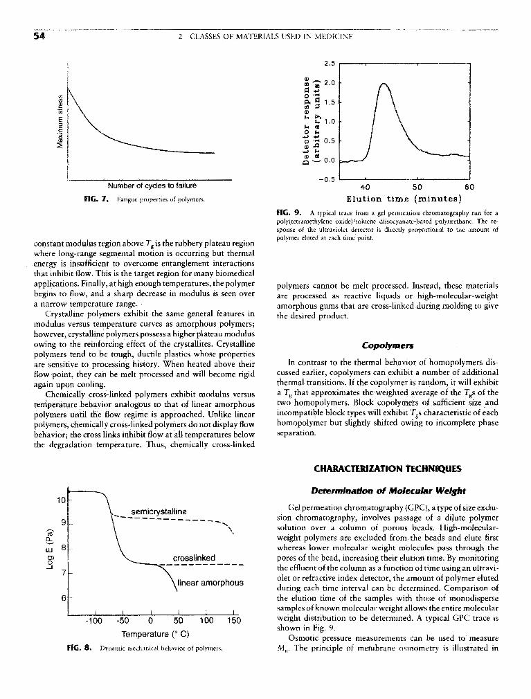
FIG. 7. Fatigue properties of polymers. Elution time (minutes)
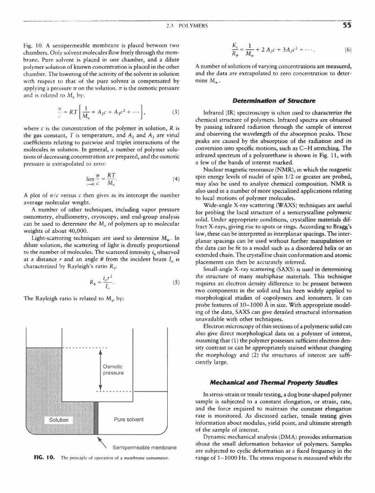
FIG. 9. A typical trace from a gel permeation chromatography run for apolyftetramethylene oxide)/toluene diisocyanate-based polyurethane. The re-sponse of the ultraviolet detector is directly proportional to the amount of
. , . _, . . , . . . polymer eluted at each time point.constant modulus region above / g is the rubbery plateau regionwhere long-range segmental motion is occurring but thermalenergy is insufficient to overcome entanglement interactionsthat inhibit flow. This is the target region for many biomedicalapplications. Finally, at high enough temperatures, the polymer polymers cannot be melt processed. Instead, these materialsbegins to flow, and a sharp decrease in modulus is seen over are prOcessed as reactive liquids or high-molecular-weighta narrow temperature range. amorphous gums that are cross-linked during molding to give
Crystalline polymers exhibit the same general features in fae desired productmodulus versus temperature curves as amorphous polymers;however, crystalline polymers possess a higher plateau modulusowing to the reinforcing effect of the crystallites. Crystalline Copotymerspolymers tend to be tough, ductile plastics whose propertiesare sensitive to processing history. When heated above their In contrast to the thermal behavior of homopolymers dis-flow point, they can be melt processed and will become rigid cussed earlier, copolymers can exhibit a number of additionalagain upon cooling. thermal transitions. If the copolymer is random, it will exhibit
Chemically cross-linked polymers exhibit modulus versus a Tg that approximates the weighted average of the Tgs of thetemperature behavior analogous to that of linear amorphous two homopolymers. Block copolymers of sufficient size andpolymers until the flow regime is approached. Unlike linear incompatible block types will exhibit Tgs characteristic of eachpolymers, chemically cross-linked polymers do not display flow homopolymer but slightly shifted owing to incomplete phasebehavior; the cross links inhibit flow at all temperatures below separation,the degradation temperature. Thus, chemically cross-linked
FIG. 8. Dynamic mechanical behavior of polymers.
2.3 POLYMERS 55
Fig. 10. A semipermeable membrane is placed between twochambers. Only solvent molecules flow freely through the mem-brane. Pure solvent is placed in one chamber, and a dilutepolymer solution of known concentration is placed in the otherchamber. The lowering of the activity of the solvent in solutionwith respect to that of the pure solvent is compensated byapplying a pressure IT on the solution. TT is the osmotic pressureand is related to Mn by:
where c is the concentration of the polymer in solution, R isthe gas constant, T is temperature, and A2 and A3 are virialcoefficients relating to pairwise and triplet interactions of themolecules in solution. In general, a number of polymer solu-tions of decreasing concentration are prepared, and the osmoticpressure is extrapolated to zero:
A plot of TT!C versus c then gives as its intercept the numberaverage molecular weight.
A number of other techniques, including vapor pressureosmometry, ebulliometry, cryoscopy, and end-group analysiscan be used to determine the Mn of polymers up to molecularweights of about 40,000.
Light-scattering techniques are used to determine Mw. Indilute solution, the scattering of light is directly proportionalto the number of molecules. The scattered intensity i0 observedat a distance r and an angle 8 from the incident beam I0 ischaracterized by Rayleigh's ratio Rf f :
The Rayleigh ratio is related to Mw by:
FIG. 1 0. The principle of operation of a membrane osmometer.
A number of solutions of varying concentrations are measured,and the data are extrapolated to zero concentration to deter-mine Mw.
Determination of Structure
Infrared (IR) spectroscopy is often used to characterize thechemical structure of polymers. Infrared spectra are obtainedby passing infrared radiation through the sample of interestand observing the wavelength of the absorption peaks. Thesepeaks are caused by the absorption of the radiation and itsconversion into specific motions, such as C—H stretching. Theinfrared spectrum of a polyurethane is shown in Fig. 11, witha few of the bands of interest marked.
Nuclear magnetic resonance (NMR), in which the magneticspin energy levels of nuclei of spin 1/2 or greater are probed,may also be used to analyze chemical composition. NMR isalso used in a number of more specialized applications relatingto local motions of polymer molecules.
Wide-angle X-ray scattering (WAXS) techniques are usefulfor probing the local structure of a semi crystalline polymericsolid. Under appropriate conditions, crystalline materials dif-fract X-rays, giving rise to spots or rings. According to Bragg'slaw, these can be interpreted as interplanar spacings. The inter-planar spacings can be used without further manipulation orthe data can be fit to a model such as a disordered helix or anextended chain. The crystalline chain conformation and atomicplacements can then be accurately inferred.
Small-angle X-ray scattering (SAXS) is used in determiningthe structure of many multiphase materials. This techniquerequires an electron density difference to be present betweentwo components in the solid and has been widely applied tomorphological studies of copolymers and ionomers. It canprobe features of 10—1000 A in size. With appropriate model-ing of the data, SAXS can give detailed structural informationunavailable with other techniques.
Electron microscopy of thin sections of a polymeric solid canalso give direct morphological data on a polymer of interest,assuming that (1) the polymer possesses sufficient electron den-sity contrast or can be appropriately stained without changingthe morphology and (2) the structures of interest are suffi-ciently large.
Mechanical and Thermal Property Studies
In stress-strain or tensile testing, a dog bone-shaped polymersample is subjected to a constant elongation, or strain, rate,and the force required to maintain the constant elongationrate is monitored. As discussed earlier, tensile testing givesinformation about modulus, yield point, and ultimate strengthof the sample of interest.
Dynamic mechanical analysis (DMA) provides informationabout the small deformation behavior of polymers. Samplesare subjected to cyclic deformation at a fixed frequency in therange of 1—1000 Hz. The stress response is measured while the

56 2 CLASSES OF MATERIALS USED IN MEDICINE
FIG. I I . Infrared spectrum of a poly(tetramethylene oxide)/toluene diisocyanate-based polyurethane.
cyclic strain is applied and the temperature is slowly increased(typically at 2—3°/min). If the strain is a sinusoidal functionof time given by:
e(<u) = e0 sin(<ut), (7)
where s is the time-dependent strain, s0 is the strain amplitude,co is the frequency of oscillation, and t is time, the resultingstress can be expressed by:
o-(tu) =o-0sin(o»t + S), (8)
where cr is the time-dependent stress, cr0 is the amplitude ofstress response, and 8 is the phase angle between stress andstrain. For Hookean solids, the stress and strain are completelyin phase (8 = 0), while for purely viscous liquids, the stressresponse lags by 90°. Real materials demonstrate viscoelasticbehavior where 8 has a value between 0° and 90°.
A typical plot of tan 8 versus temperature will display max-ima at Tg and at lower temperatures where small-scale motions(secondary relaxations) can occur. Additional peaks above Tg,corresponding to motions in the crystalline phase and melting,are seen in semicrystalline materials. DMA is a sensitive toolfor characterizing polymers of similar chemical composition orfor detecting the presence of moderate quantities of additives.
Differential scanning calorimetry is another method forprobing thermal transitions of polymers. A sample cell and areference cell are supplied energy at varying rates so that thetemperatures of the two cells remain equal. The temperatureis increased, typically at a rate of 10—20°/mm over the rangeof interest, and the energy input required to maintain equalityof temperature in the two cells is recorded. Plots of energysupplied versus average temperature allow determination of
Tg, crystallization temperature (Tc), and Tm. Tg is taken as thetemperature at which one half the change in heat capacity,AQ?, has occurred. The Tc and Tm are easily identified, asshown in Fig. 12. The areas under the peaks can be quantita-tively related to enthalpic changes.
Surface Characterization
Surface characteristics of polymers for biomedical applica-tions are critically important. The surface composition is inevi-
F1G. 12. Differential scanning calorimetry thermogram of a semicrystal-line polymer.

2.3 POLYMERS 57
Ear & ear parts: acrylic, polyethylene, silicone, poly(vinyt chloride) (PVC)Dentures: acrylic, ultrahigh molecular weight polyethylene (UHMWPE), epoxyFacial prosthesis: acrylic, PVC, polyurethane (PUR)Trachea! tubes: acrylic, silicone, nylonHeart & heart components: polyester, silicone, PVCHeart pacemaker: polyethylene, acetalLung, kidney & liver parts: polyester, polyaldehyde, PVCEsophagus segments: polyethylene, polypropylene (PP), PVCBlood vessels: PVC, polyesterBiodegradable sutures: PURGastrointestinal segments: silicones, PVC, nylonFinger joints: silicone, UHMWPEBones & joints: acrylic, nylon, silicone, PUR, PP, UHMWPEKnee joints: polyethylene
FIG. 13. Common clinical applications and types of polymers used in medicine.(From D. V. Rosato, in Biocompatible Polymers, Metals, and Composites, M. Szycher,ed., Technomic Publ., 1983, p. 1022, with permission.)
tably different from the bulk, and the surface of the material Poly(methyl methacrylate) (PMMA) is a hydrophobic, lin-is generally all that is contacted by the body. The main surface ear chain polymer that is glassy at room temperature and maycharacterization techniques for polymers are X-ray photoelec- be more easily recognized by such trade names as Lucite ortron spectroscopy (XPS), contact angle measurements, attenu- Plexiglas. It has very good light transmittance, toughness, andated total reflectance Fourier transform infrared (ATR-FTIR) stability, making it a good material for intraocular lenses andspectroscopy, and scanning electron microscopy (SEM). The hard contact lenses.techniques are discussed in detail in Chapter 1.3. Soft contact lenses are made from the same family of poly-
mers, with the addition of a —CH2OH group to the methylmethacrylate side group, resulting in 2-hydroxyethyl methacry-late (HEMA). The additional methylol group causes the poly-
CLASSES Of POLYMERS USED IN MEDICINE mer to be hydrophilic. For soft contact lenses the poly(HEMA)is slightly cross-linked with ethylene glycol dimetnyacrylate(EGDM) to prevent the polymer from dissolving when it is
Many types of polymers are used for biomedical purposes. hydrated (Rodriguez, 1982). Fully hydrated, it is a swollenFigure 13 illustrates the variety of clinical applications for hydrogel. This class of polymers is discussed in more detail inpolymeric biomaterials. This section discusses some of the poly- Chanter 2 4
mers used in medicine. Polyethylene (PE) is used in its high-density form in biomedi-cal applications because low-density material cannot withstandsterilization temperatures. It is used in tubing for drains and
Homooolvmers catheters, and in very high-molecular-weight form as the ace-tabular component in artificial hips. The material has good
Homopolymers are composed of a single type of monomer. toughness, resistance to fats and oils, and a relatively low cost.Figure 14 shows the repeat units of many of the homopolymers Polypropylene (PP) is closely related to PE and has highused in medicine. rigidity, good chemical resistance, and good tensile strength.

S8 2 CLASSES OF MATERIALS USED IN MEDICINE
FIG. 14. Homopolyniers used in medicine.

2.3 POLYMERS 59
FIG. 1 5. Copolymers and their base monomers used in medicine.
Its stress cracking resistance is superior to that of PE, and it carbonate, a clear, tough material. Its high impact strengthis used for many of the same applications as PE. dictates its use as lenses for eyeglasses and safety glasses, and
Poly(tetrafluoroethylene) (PTFE), also known as Teflon, has housings for oxygenators and heart-lung bypass machine,the same structure as PE, except that the hydrogen in PE is Nylon is the name given by Du Pont to a family of polyam-replaced by fluorine. PTFE is a very stable polymer, both ther- ides. Nylons are formed by the reaction of diamines with diba-mally and chemically, and as a result it is very difficult to sic acids or by the ring opening polymerization of lactams.process. It is very hydrophobic and has excellent lubricity. In Nylons are used in surgical sutures,microporous (Gore-Tex) form, it is used in vascular grafts.
Poly(vinyl chloride) (PVC) is used mainly in tubing in bio-medical applications. Typical tubing uses include blood trans- CoDOtvtltersfusion, feeding, and dialysis. Pure PVC is a hard, brittle mate-rial, but with the addition of plasticizers, it can be made flexible Copolymers are another important class of biomedical ma-and soft. PVC can pose problems for long-term applications terials. Fig. 15 shows two different copolymers used in medi-because the plasticizers can be extracted by the body. While cine. Poly(glycolide lactide) (PGL) is a random copolymer usedthese plasticizers have low toxicities, their loss makes the PVC in resorbable surgical sutures. PGL polymerization occurs vialess flexible. a ring-opening reaction of a glycolide and a lactide, as illus-
Poly(dimethyl siloxane) (PDMS) is an extremely versatile trated in Fig. 15. The presence of ester linkages in the polymerpolymer. It is unique in that it has a silicon-oxygen backbone backbone allows gradual hydrolytic degradation (resorption).instead of a carbon backbone. Its properties are less tempera- In contrast to the natural resorbable suture material poly(gly-ture sensitive than other rubbers because of its lower Tg. PDMS colic acid), or catgut, a homopolymer, the PGL copolymeris used in catheter and drainage tubing, in insulation for pace- retains more of its strength over the first 14 days after implanta-maker leads, and as a component in some vascular graft sys- tion (Chu, 1983).terns. It is used in membrane oxygenators because of its high A copolymer of tetrafluoroethylene and hexafluoropropy-oxygen perrnability. Because of its excellent flexibility and sta- lene (FEP) is used in many applications similar to those ofbility, it is also used in a variety of prostheses such as finger PTFE. FEP has a crystalline melting point near 265°C comparedjoints, blood vessels, heart valves, breast implants, outer ears, with 327°C for PTFE. This enhances the processibility of FEPand chin and nose implants (Rosato, 1983). compared with PTFE while maintaining the excellent chemical
Polymerization of bisphenol A and phosgene produces poly- inertness and low friction characteristic of PTFE.

60 2 CLASSES OF MATERIALS USED IN MEDICINE
Poiyurethanes are block copolymers containing "hard" and van der Waals interactions between chains (Peppas, 1987),"soft" blocks. The "hard" blocks, having Tgs above room Hydrogels have received significant attention, especially in thetemperature and acting as glassy or semicrystalline reinforcing past 30 years, because of their exceptional promise in hiomedi-blocks, are composed of a diisocyanate and a chain extender, cal applications. The classic book by Andrade (1976) offersThe diisocyanates most commonly used are 2,4-toluene diiso- some of the best work that was available prior to 1975. Thecyanate (TD1) and methylene di(4-phenyl isocyanate) (MDI), more recent book by Peppas (1987) addresses the preparation,with MDI being used in most biomaterials. The chain extenders structure, and characterization of hydrogeis. In this chapter,are usually shorter aliphatic glycol or diamine materials with we concentrate on some features of the preparation of hydro-2-6 carbon atoms. The "soft" blocks in polyurethanes are gels, as well as characteristics of their structure and chemicaltypically polyether or polyester polyols whose Tgs are much and physical properties,less than room temperature, allowing them to give a rubberycharacter to the materials. Polyether polyols are more com-monly used for implantable devices because they are stable tohydrolysis. The polyol molecular weights tend to be on the CLASSIFICATION AND BASIC STRUCTUREorder of 1000 to 2000.
Polyurethanes are tough elastomers with good fatigue and T T . . . . .r . , . . ..i i j - T~L j • i i j Hydrogeis may be classified in several ways, depending onblood-corttaining properties. I hey are used in pacemaker lead . . ' . , ' . . . . , . ,
, . , c , . , ,, , their method of preparation, ionic charge, or physical structureinsulation, vascular grafts, heart assist balloon pumps, and , _, , , \ i /• • i.r . i i LI j j features. Based on the method of preparation, they are (1)artificial heart bladders. . . . . . . ... , r r ' / ; .
homopolymer hydrogeis, (2) copolymer hydrogeis, (3) multi-polymer hydrogeis, and (4) interpenetrating polymeric hydro-
BiblloeraDhv ge\$. Homopolymer hydrogeis are cross-linked networks ofone type of hydrophilic monomer unit, whereas copolymer
Billmeyer, F. W., Jr. (1984). Textbook of Polymer Science, 3rd ed. hydrogeis are produced by cross-linking of two comonomerWiley-Interscience, New York. units, one of which must be hydrophilic. Multipolymer hydro-
Bovey, F. A., and Winslow, F. H. (1979). Macromolecules: An Intro- gels are produced from three or more comonomers reactingduction to Polymer Science. Academic Press, Orlando, FL. together. Finally, interpenetrating polymeric hydrogeis are pro-
Chu,C.C.(1983).Surveyofciimcallyimportantwoundclosurebioma- duced b swdli fl fir§t n£twork m a monomer and reactl
terials, in Biocompatible Polymers, Metals, and Composites, M. , , r , . , . ,P , j -r i • n LI r n* ATT rt-> t"6 latter to form a second intermeshmg network structure.Szycher, ed. lechnomic Publ., Lancaster, PA, pp. 477-523. « i . • • • i 11 f i i •/- i
Hory.PJ. (1953). Prtm^teo^Pofy^awmsfry. Cornell University Based °n theu" 1OI11C char8es> Mrogels may be classifiedPress London. (Ratner and Hoffman, 1976) as (1) neutral hydrogeis, (2) an-
Lelah, M. D., and Cooper, S. L. (1986). Polyurethanes in Medicine. ionic hydrogeis, (3) cationic hydrogeis, and (4) ampholyticCRC Press, Boca Raton, FL. hydrogeis. Based on physical structural features of the system,
Mandelkerti, L. (1983). An Introduction to Macromolecules. Springer- they can be classified as (1) amorphous hydrogeis, (2) semicrys-Verlag, New York. talline hydrogeis, and (3) hydrogen-bonded structures. In
Rodriguez, F.(l 982). Principles of Polymer Systems, 2nd ed.McGraw- amorphous hydrogeis, the macromolecular chains are ran-Hill, New York. dornly arranged, whereas semicrystalline hydrogeis are charac-
Rosato, D. V. (1983). Polymers, processes and properties of medical tedzed by deme regions of ordered macromolecular chainsplastics: including markets and applications, m Biocompatible (crystallites). Often, hydrogen bonds may be responsible forPolymers, Metals, and Composites, M. Szycher, ed. Technomic the three-dimensional structure formed.PubL, Lancaster, PA , pp . 1019-1067. c. r i . - r u j i i k ^ - j i »
„ n o 1 ^ 1 -- ^ r / i Q o o N n ; ^i Structural evaluation of hydrogeis reveals that ideal net-Seymour, R . B., a n d Carraker, C . f c . J r . (1988). Polymer Chemistry: , , 1 1 j r - i i . - j i
. ' j . _ , j ,., i rv 11 XT v r works are only rarely observed, rigure la shows an ideal mac-An Introduction, 2nd ed. Marcel Dekker, New York. , , ' , ,, , ,. ° . .. , . ,c r T u /IOQS\ j t j *• * T>L • i D i c romolecular network (hydrogel) indicating tetratunctionalSperling, L. H. (1986). Introduction to Physical Polymer Science. .. . ,. . ^ v J. &. / , ° , T T
Wiley-Interscience New York cross-links (junctions) produced by covalent bonds. However,Stokes, K., and Chem. B. (1984). Environmental stress cracking in the Possibility exists of multifunctional junctions (Fig. Ib) or
implanted polyether polyurethanes, in Polyurethanes in Biomedical physical molecular entanglements (Fig. 1 c) playing the role ofEngineering, H. Planck, G. Engbers, and I. Syre, eds. Elsevier, Am- semipermanent junctions. Hydrogeis with molecular defectssterdam. are always possible. Figures Id and le indicate two such effects:
unreacted functionalities with partial entanglements (Fig. Id)and chain loops (Fig. le). Neither of these effects contributesto the mechanical or physical properties of a polymer network.
The terms "junction" and "cross-link" (an open circle sym-bol in Fig. Id) indicate the connection points of several chains.
•% m mm This junction may be ideally a carbon atom, but it is usually£,•** FlYPKCKjlLb a smaii chemical bridge [e.g., an acetal bridge in the case of
Nikolaos A. Peppas poly(vinyl alcohol)] of molecular weight much smaller thanthat of the cross-linked polymer chains. In other situations, a
Hydrogeis are water-swollen, cross-linked polymeric struc- junction may be an association of macromolecular chainstures produced by the simple reaction of one or more monomers caused by van der Waals forces, as in the case of the glycopro-or by association bonds such as hydrogen bonds and strong teinic network structure of natural mucus, or an aggregate

2.4 HYDROGELS 61
FIG. 1. (A) Ideal macromolecular network of a hydrogel. (B) Network with multifunctional junctions. (C) Physical entangle-ments in a hydrogel. (D) Unreacted functionality in a hydrogel. (E) Chain loops in a hydrogel.
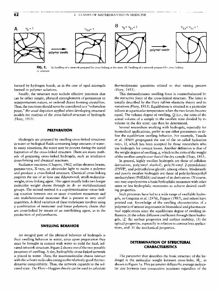
62 2 CLASSES OF MATERIALS USED IN MEDICINE
FIG. 2. (A) Swelling of a network prepared by cross-linking in dry state. (B) Swelling of a network prepared by cross-linkingin solution.
formed by hydrogen bonds, as in the case of aged microgels thermodynaniic quantities related to that mixing processformed in polymer solutions. (Flory, 1953).
Finally, the structure may include effective junctions that This thermodynaniic swelling force is counterbalanced bycan be either simple, physical entanglements of permanent or the retractive force of the cross-linked structure. The latter issemipermanent nature, or ordered chains forming crystallites. usually described by the Flory rubber elasticity theory and itsThus, the junctions should never be considered as a "volumeless variations (Flory, 1953). Equilibrium is attained in a particularpoint," the usual depiction applied when developing structural solvent at a particular temperature when the two forces becomemodels for analysis of the cross-linked structure of hydrogels equal. The volume degree of swelling, Q (i.e., the ratio of the(Flory, 1953). actual volume of a sample in the swollen state divided by its
volume in the dry state) can then be determined.Several researchers working with hydrogels, especially for
rKtr/VKAIIvJlN biomedical applications, prefer to use other parameters to de-fine the equilibrium swelling behavior. For example, Yasuda
Hydrogels are prepared by swelling cross-linked structures et al. (1969) propagated the use of the so-called hydrationin water or biological fluids containing large amounts of water. ratio, H, which has been accepted by those researchers whoIn many situations, the water may be present during the initial use hydrogels for contact lenses. Another definition is that offormation of the cross-linked structure. There are many meth- the weight degree of swelling, q, which is the ratio of the weightods of preparing cross-linked hydrogels, such as irradiative of the swollen sample over that of the dry sample (Flory, 1953).cross-linking and chemical reactions. In general, highly swollen hydrogels are those of cellulose
Radiation reactions (Chapiro, 1962) utilize electron beams, derivatives, poly(vinyl alcohol), poly(N-vinyl 2-pyrrolidone)gamma-rays, X-rays, or ultraviolet light to excite a polymer (PNVP), and polyethylene glycol), among others. Moderatelyand produce a cross-linked structure. Chemical cross-linking and poorly swollen hydrogels are those of poly(hydroxyethyirequires the use of at least one difunctional, small-molecular- methacrylate) (PHEMA) and many of its derivatives. Of course,weight, cross-linking agent. This agent usually links two longer one may copolymerize a basic hydrophilic monomer with othermolecular weight chains through its di- or multifunctional more or less hydrophilic monomers to achieve desired swell -groups. The second method is a copolymerization—cross-link- ing properties.ing reaction between one or more abundant monomers and Such processes have led to a wide range of swellable hydro-one multifunctional monomer that is present in very small gels, as Gregonis et al. (1976), Peppas (1987), and others havequantities. A third variation of these techniques involves using pointed out. Knowledge of the swelling characteristics of aa combination of monomer and linear polymeric chains that polymer is of utmost importance in biomedical and pharmaceu-are cross-linked by means of an interlinking agent, as in the tical applications since the equilibrium degree of swelling in-production of polyurethanes. fluences (1) the solute diffusion coefficient through these hydro-
gels, (2) the surface properties and surface mobility, (3) theCIA/EI i iiuf BEUAi/irfcD optical properties, especially in relation to contact lens applica-SWELLING BEHAVIOR tionS5 and (4) thg mechamcal prOperties.
An integral part of the physical behavior of hydrogels istheir swelling behavior in water, since upon preparation theymust be brought in contact with water to yield the final, sol- DETERMINATION Of STRUCTURALvated network structure. Figure 2 shows one of the two possible CHARACTERISTICSprocesses of swelling. A dry, hydrophilic cross-linked networkis placed in water. Then, the macromolecular chains interact The parameter that describes the basic structure of the hy-with the solvent molecules owing to the relatively good thermo- drogel is the molecular weight between cross-links, Mc, asdynamic compatibility. Thus, the network expands to the sol- shown in Figure la. This parameter defines the average molecu-vated state. The Flory-Huggins theory can be used to calculate lar size between two consecutive junctions regardless of the
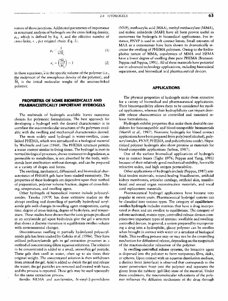
2.4 HYDROGELS 63
nature of those junctions. Additional parameters of importancein structural analysis of hydrogels are the cross-linking density,px, which is defined by Eq. 1, and the effective number ofcross-links, i>,, per original chain (Eq. 2).
In these equations, v is the specific volume of the polymer (i.e.,the reciprocal of the amorphous density of the polymer), andMn is the initial molecular weight of the uncross-linkedpolymer.
PROPERTIES Of SOME BIOMEDICALLY ANDPHARMACEUTICALLY IMPORTANT HYDROGELS
The multitude of hydrogels available leaves numerouschoices for polymeric formulations. The best approach fordeveloping a hydrogel with the desired characteristics is tocorrelate the macromolecular structures of the polymers avail-able with the swelling and mechanical characteristics desired.
The most widely used hydrogel is water-swollen, cross-linked PHEMA, which was introduced as a biological materialby Wichterle and Lim (1960). The PHEMA structure permitsa water content similar to living tissue. The hydrogel is inert tonormal biological processes, shows resistance to degradation, ispermeable to metabolites, is not absorbed by the body, with-stands heat sterilization without damage, and can be preparedin a variety of shapes and forms.
The swelling, mechanical, diffusional, and biomedicai char-acteristics of PHEMA gels have been studied extensively. Theproperties of these hydrogels are dependent upon their methodof preparation, polymer volume fraction, degree of cross-link-ing, temperature, and swelling agent.
Other hydrogels of biomedicai interest include polyacryl-amides. Tanaka (1979) has done extensive studies on theabrupt swelling and deswelling of partially hydrolyzed acryl-amide gels with changes in swelling agent composition, curingtime, degree of cross-linking, degree of hydrolysis, and temper-ature. These studies have shown that the ionic groups producedin an acrylamide gel upon hydrolysis give the gel a structurethat shows a discrete transition in equilibrium swollen volumewith environmental changes.
Discontinuous swelling in partially hydrolyzed polyacryl-amide gels has been studied by Gehrke et al. (1986). They haveutilized polyacrylamide gels in gel extraction processes as amethod of concentrating dilute aqueous solutions. The solutionto be concentrated is added to a small, unswollen gel particle.These gels then swell in water, often up to six times theiroriginal weight. The concentrated solution is then withdrawnfrom around the gel. Acid is added to shrink the gel and releasethe water; the gel particles are removed and treated with base;and the process is repeated. These gels may be used repeatedlyfor the same extraction process.
Besides HEMA and acrylamides, N-vinyl-2-pyrrolidone
(NVP), methacrylic acid (MAA), methyl methacrylate (MMA),and maleic anhydride (MAH) have all been proven useful asmonomers for hydrogels in biomedicai applications. For in-stance, PNVP is used in soft contact lenses. Small amounts ofMAA as a comonomer have been shown to dramatically in-crease the swelling of PHEMA polymers. Owing to the hydro-phobic nature of MMA, copolymers of MMA and HEMAhave a lower degree of swelling then pure PHEMA (Brannon-Peppas and Peppas, 1991). All of these materials have potentialuse in advanced technology applications, including biomedicaiseparations, and biomedicai and pharmaceutical devices.
APPLICATIONS
The physical properties of hydrogels make them attractivefor a variety of biomedicai and pharmaceutical applications.Their biocompatibility allows them to be considered for medi-cal applications, whereas their hydrophilicity can impart desir-able release characteristics to controlled and sustained re-lease formulations.
Hydrogels exhibit properties that make them desirable can-didates for biocompatible and blood-compatible biomaterials(Merrill et al., 1987). Nonionic hydrogels for blood contactapplications have been prepared from poly(vinyl alcohol), poly-acrylamides, PNVP, PHEMA, and poly(ethylene oxide). Hepa-rinized polymer hydrogels also show promise as materials forblood-compatible applications (Sefton, 1987).
One of the earliest biomedicai applications of hydrogelswas in contact lenses (Tighe 1976; Peppas and Yang, 1981)because of their relatively good mechanical stability, favorablerefractive index, and high oxygen permeability.
Other applications of hydrogels include (Peppas, 1987) arti-ficial tendon materials, wound-healing bioadhesives, artificialkidney membranes, articular cartilage, artificial skin, maxillo-facial and sexual organ reconstruction materials, and vocalcord replacement materials.
Pharmaceutical hydrogel applications have become verypopular in recent years. Pharmaceutical hydrogel systems canbe classified into various types. The category of equilibrium-swollen hydrogels includes matrices that have a drug incorpo-rated in them and are swollen to equilibrium. The category ofsolvent-activated, matrix-type, controlled-release devices com-prises two important types of systems: swellabie and swelling-controlled devices. In general, a system prepared by incorporat-ing a drug into a hydrophilic, glassy polymer can be swollenwhen brought in contact with water or a simulant of biologicalfluids. This swelling process may or may not be the controllingmechanism for diffusional release, depending on the magnitudeof the macromolecular relaxation of the polymer.
In swelling-controlled release systems, the bioactive agentis dispersed into the polymer to form nonporous films, disks,or spheres. Upon contact with an aqueous dissolution medium,a distinct front (interface) is observed that corresponds to thewater penetration front into the polymer and separates theglassy from the rubbery (gel-like) state of the material. Underthese conditions, the macromolecular relaxations of the poly-mer influence the diffusion mechanism of the drug through

64 2 CLASSES OF MATERIALS USED IN MEDICINE
the rubbery state. This water uptake can lead to considerable Ratner, B. D., and Hoffman, A. S. (1976). Synthetic hydrogelsswelling of the polymer with a thickness that depends on time. for biomedical applications, in Hydrogels for Medical andThe swelling process proceeds toward equilibrium at a rate Related Applications, J. D. Andrade, ACS Symposium Series,determined by the water activity in the system and the structure Amencan Chermcal Society, Washington, DC, Vol. 31, pp.
of the polymer. If the polymer is cross-linked or of sufficiently M y g HeParmized hydrogels. m Hydrogels in Medtanehigh molecular weight (so that chain entanglements can mam- and Pharmac% N. A peppaSj ed CRC Press> Boca Raton5 FL? VoL
tain structural integrity), the equilibrium state is a water-swol- 3^ 17-52.len gel. The equilibrium water content of such hydrogels can Tanaka, T. (1979). Phase transitions in gels and a single polymer.vary up to more than 90%. If the dry hydrogel contains a Polymer 20: 1404-1412.water-soluble drug, the drug is essentially immobile in the Tighe, B. J. (1976). The design of polymers for contact lens applica-glassy matrix, but begins to diffuse out as the polymer swells tions. Brit. Polym. J. 8: 71-90.with water. Drug release thus depends on two simultaneous Wichterle, O., and Lira, D. (1960). Hydrophilic gels for biological use.rate processes: water migration into the device and drug diffu- Nature 185: 11 / -118.
^ i . i . M i c - _ «. ^ i Yasuda, H., Peterlin, A., Colton, C. K., Smith, K. A., and Merrill,sion outward through the swollen gel. Since some water uptake ' . ' 0. ' ' ... ' ' ' . ,' , . ', , i j L i J L - - - I I L E. W. (1969). Permeability of solutes through hydrated polymermust occur before the drug can be released, the initial burst , ' _, . , , , , , °, , . . /,. ,
. . . . . , , . membranes. 111. 1 neoretical background tor the selectivity or dial-effect frequently observed in matrix devices is moderated, al- ysis membranes- MakromoL chemte 126: 177-186.though it may still be present. 1he continued swelling of the Yoshio5 N Hirohito, N., and Matsuhiko, M. (1986). Propertiesmatrix causes the drug to diffuse increasingly easily, ameliorat- Of swelling and shrinking. /. Chem. Eng. Japan 19: 274-ing the slow tailing off of the release curve. The net effect of 280.the swelling process is to prolong and linearize the releasecurve. Additional discussion of controlled release systems fordrug delivery can be found in Chapter 7.8. 2.5 BlORESORBABLE AND
Details of these experimental techniques have been pre- Rir«;i»r%rfciiM c MATCDIAICsented by Korsmeyer and Peppas (1981) for poly(vinyl alchol) BIOERODIBLE MATERIALSsystems, and by Peppas (1981) for PHEMA systems and Joachim Kohn and Robert Langer
their copolymers.TYPES OF IMPLANTS
Bibliography Since a degradable polymeric implant does not have to be. , , ^ „ „ „ . , , , , , f ,„ ,. , , n • i A ,• removed surgically once it is no longer needed, degradableAndrade, I. D. (1976 . Hydrogels for Medical and Related Appltca- , r « • u i- • LA / - C C c • \r i 01 A • /-u - i c polymers are of value in short-term applications that requiretions. ACS Symposium Series, Vol. 31, American Chemical Society, , , c i • • i » u -
Wa hin ton DC ° ^ temporary presence or a polymeric implant. An addi-Brannon-Peppas, L, and Peppas, N. A. (1991). Equilibrium swelling tional advantage is that the use of degradable implants can
behavior of dilute ionic hydrogels in electrolytic solutions. /. Con- circumvent some of the problems related to the long-term safetytrolled Release 16: 319-330. of permanently implanted devices. Some typical short-term
Chapiro, A. (1962). Radiation Chemistry of Polymeric Systems. Inter- applications are listed in Table 1. From a practical perspective,science, New York. it is convenient to distinguish among four main types of degrad-
Flory, P. J. (1953). Principles of Polymer Chemistry. Cornell UniversityPress, Ithaca, NY.
Gehrke, S. H., Andrews, G. P., and Cussler, E. L. (1986). Chemicalaspects of gel extraction. Chem. Eng. Sci. 41: 2153—2160.
Gregonis, D.E., Chen, CM., and Andrade,J.D. (1976). The chemistry TABL£ , Some «short.Tenn» Medjcal Applications ofof some selected methacrylate hydrogels, in Hydrogels for Medical „ , , , _. , . n, . .
j 0 , , . ,, • r r\ A j j j Afc c • Degradable Polymeric Biomatenalsand Related Applications. J. D. Andrade, ed. ACS Symposium & 7
Series, VoL 31, pp. 88—104, American Chemical Society, Washing-DC Application Comments
Ilavsky, M. (1982). Phase transition in swollen gels. Macromolecutes15- 782—788 Sutures The earliest, successful application of synthetic,
Korsmeyer, R. W., and Peppas, N. A. (1981). Effects of the morphology degradable polymers in human medicine.of hydrophilic polymeric matrices on the diffusion and release of Drug delivery One of the most widely investigated medicalwater soluble drugs. /. Membr. Sci 9: 211—227. devices applications for degradable polymers.
Merrill, E. W., Pekala, P. W., and Mahmud, N. A. (1987). Hydro- Orthopedic fixa- Requires polymers of exceptionally high me-gels for blood contact, in Hydrogels in Medtcme and Pharmacy, don devices chamcal strength and stiffness.N. A. Peppas, ed. CRC Press, Boca Raton, FL, Vol. 3, pp. 1-1 ̂ Adhesion pre- Requires polymers that can form soft mem-
Peppas, N. A. (1987). Hydrogels in Medicine and Pharmacy. CRC vention branes or films.Press, Boca Raton, FL. Temporary vascu- Only investigational devices are presently avail-
Peppas, N. A., and Yang, W. H. M. (1981). Properties-based optimiza- lar grafts and able. Blood compatibility is a major concern.tion of the structure of polymers for contact lens applications. stentsContact Intraocular Lens Med. J. 7: 300—321. ..-

84 2 CLASSES OF MATERIALS USED IN MEDICINE
Hench, L. L. (1994), Bioactive ceramics: Theory and clinical applica- White, E., and Schors, E. C, (1986). Biomaterials aspects of interpore-tions in Bioceramics-7, O, H. Anderson and A. Yli-Urpo, eds. 200 porous hydroxyapatite. Dent. Clin. North Am, 30: 49-67.Butterworth-Heinemann, Oxford, England, pp. 3-14. Wilson,]. (1994). Clinical Applications of Bioglass Implants, in Biocer-
Hench, L. L., and Clark, D. E. (1978). Physical chemistry of glass amics-7, O. H. Andersson, ed. Butterworth-Heinemann, Ox-surfaces. J. Non-Cryst. Solids 28(1):83-105. tord, England.
Hench, L. L, and Ethridge, E. C. (1982). Biomaterials: An Interfacial Wilson,']., Pigott, G. H., Schoen, F. J., and Hench, L. L. (1981).Approach. Academic Press, New York. Toxicology and biocompatibility of bioglass. /. Biomed. Mater.
Hench, L. L., and Wilson, J. W. (1993). An Introduction to Bioce- ges j r . gQ^
ramies, World Saentific Smgapore. Yamamuro", T., Hench, L. L., Wilson, J. (1990). Handbook on Btoac-Hench, L, L., and Wilson, . W. (1996). Clinical Performance or Skele- ,,-, ,, , , „ - ,-,, , ,-,, ^ » , ,. ' . __,, J i ,r n T i tive (Ceramics, Vol. I: Bioactive Glasses and Glass-Ceramics, Vol.
tal Prostheses, Chapman and Hall, London. „ ,, , , „, . „ . „_ „ „ „ ,.. .,,r r i T r r r n T A I I wr /-< j r- i i -r v ": Calcium-Phosphate Ceramics, CKC Press, Boca Raton, rL.Hench, L. L., Splinter, R. ]., Allen, W. C., and Greenlec, Jr. T. K. * '
(1972). Bonding mechanisms at the interface of ceramic prostheticmaterials. /, ftiomed. Res. Symp. No. 2. Interscience, New York,
P 117 2.7 NATURAL MATERIALSHoland, W., and Vogel, V. (1993). Machineable and phosphate glass- loannis V Yannas
ceramics, in An Introduction to Bioceramics, L. L. Hench and J.Wilson, eds. World Scientific, Singapore, pp. 125-138.
Hulbert, S. (1993). The use of alumina and zirconia in surgical im- Natural polymers offer the advantage of being very similar,plants, in An Introduction to Bioceramics, L. L. Hench and J. often identical, to macromolecular substances which the bio-Wilson, eds. World Scientific, Singapore, pp. 25-40. logical environment is prepared to recognize and to deal with
Hulbert, S. F., Bokros, I. C.. Hench, L. L., Wilson, ]., and Heimke, _ , ,• ,, /-r LI t\ -ri_ r i r^ . • • j ^- i„ ,\Qoi\ /- • i • ! i• • n j metabohcally (lable 1). I he problems of toxicity and stimula-G. (1987). Ceramics m clinical applications: Past, present, and ' r 1 1 , -future, in High Tech Ceramics, P. Vincenzini, ed. Elsevier, Amster- tlon of a chronic inflammatory reaction, which are frequentlydam, pp. 189-213. provoked by many synthetic polymers, may thereby be sup-
Jarcho, M. (1981). Calcium phosphate ceramics as hard tissue prosthet- pressed. Furthermore, the similarity to naturally occurring sub-ics. Clin. Orthop. Relat. Res. 157: 259. stances introduces the interesting capability of designing bio-
Kokubo, T. (1993). A/W glass-ceramics: Processing and properties. materials which function biologically at the molecular, ratheri n A n Introduction t o Bioceramics, L . L . Hench a n d I . Wilson, L L • i i /-v 1 i i j i tj wr u c •£ c- -re oo than the macroscopic, level. On the other hand, natural poly-eds. World Saentific, Singapore, p p . 75-88. , , . , „ . \
Lacefield, W. R. (1993). Hydroxylapatite coatings, in An Introduction mers are frequently quite immunogemc. Furthermore, becauseto Bioceramics, L. L. Hench and J. Wilson, eds. World Scientific, they are structurally much more complex than most syntheticSingapore, pp. 223-238. polymers, their technological manipulation is much more elab-
Le Geros, R. Z, (1988). Calcium phosphate materials in restorative orate. On balance, these opposing factors have conspired todensitry: a review. Adv. Dent. Res. 2: 164-180. [ead to a substantial number of biomaterials applications in
Le Geros, R. Z., and Le Geros, J. P. (1993) Dens hydroxyapatite. m whkh naturall occurring polymers, or their chemically modi-An Introduction to Bioceramics, L. L. Hench and J. Wilson, eds. r . . . . . , . . , .World Scientific, Singapore, pp. 139-180. fied ve™°ns, have provided unprecedented solutions.
McKinney, Jr., R. V., and Lemons, J. (1985). The Dental Implant, An intriguing characteristic of natural polymers is theirPSG Pub!., Littleton, MA. ability to be degraded by naturally occurring enzymes, a virtual
McMillan, P. W. (1979). Glass-Ceramics, Academic Press, New York. guarantee that the implant will be eventually metabolized byMiller, j. A., Talton, J. D., and Bhatia, S. (1996). in Clinical Perfor- physiological mechanisms. This property may, at first glance,
mance of Skeletal Prostheses, L. L. Hench and J. Wilson, eds. pear as a disadvantage smce lt detracrs from the durabilityChapman and Hall, London, pp . 41—56. /• ' i • i n - i t i i
M i T v T i_r u- c v i u T j u c °t tne ittiplant. However, it has been used to advantage inNakamura, T., Yamumuro, T., Higashi, S., Kokubo, T., and Itoo, S. r ' &
(1985). A new glass-ceramic for bone replacement: Evaluation of biomaterials applications in which it is desired to deliver aits bonding to bone tissue. /. Biomed. Mater. Res. 19: 685. specific function for a temporary period of time, following
Onoda, G., and Hench, L. L. (1978). Ceramic Processing Before Firing. which the implant is expected to degrade completely and toWiley, New York. be disposed of by largely normal metabolic processes. Since,
Phillips R. W. (1991). Skinners Science of Dental Materials, 9th Ed., furthermore, it is possible to control the degradation rate of theRalph W. Phillips, ed. Saunders, Philadelphia. i • , L i • i i- i • i i • i
D , D c i i c i \* A / iooo\ o- i implanted polymer by chemical cross-linking or other chemicalReck, R., Storkel, S., and Meyer, A. (1988). Bioactive glass-ceramics j ._ , , ffin middle ear surgery: an 8-year review, in Bioceramics: Materials modifications, the designer is offered the opportunity to controlCharacteristics versus In-Vivo Behavior, P. Ducheyne and J. Lem- the lifetime of the implant.ons, eds. Ann. New York Acad. Sci., Vol. 523, p. 100. A disadvantage of proteins on biomaterials is their fre-
Reed, J. S. (1988). Introduction to Ceramic Processing. Wiley, New quently significant immunogenicity, which, of course, derivesYor^' precisely from their similarity to naturally occurring sub-
Rltte^-la E~; I1"" ̂ eenSp3n' D- uC" P T' R' Ai'/nd Hend?' L' L' stances. The immunological reaction of the host to the implant{iy/9). Use or fracture mechanics theory in lifetime predictions . . . . . . . . . . . . . . ,for alumina and bioglass-coated alumina. /. Biomed. Mater. Res. 1S directed agamst selected Sltes (antigemc determinants) in the13: 251-263. protein molecule. This reaction can be mediated by molecules
Roy, D. M., and Linnehan, S. K. (1974). Hydroxyapatite formed in solution in body fluids (immunoglobulins). A single suchfrom coral skeletal carbonate by hydrothermal exchange. Nature molecule (antibody) binds to single or multiple determinants247: 220-222. on an antigen. The immunological reaction can also be medi-
Schors E. C and Holmes, R. E. (1993). Porous hydroxyapatite. in ated b molecules whlch are hdd ti hd to the surface of
An Introduction to Bioceramics, L. L. Hench and I. Wilson, eds. . ,. ,, , . ™, . , ,, ,World Scientific, Smgapore, pp. 181-198. Immune cells (lymphocytes). The implant is eventually de-
Stanley, H. R., Clark, A. E., and Hench, L. L. (1996). Alveolar ridge graded. The reaction can be virtually eliminated provided thatmaintenance implants, in Clinical Performance of Skeletal Prosthe- the antigenic determinants have been previously modifiedses, Chapman and Hall, London, pp. 237-254. chemically. The immunogenicity of polysaccharides is typically

2.7 NATURAL MATERIALS 85
TABLE 1 General Properties of Certain Natural Polymers
Polymer Incidence Physiological function
A. ProteinsSilk Synthesized by arthropods Protective cocoonKeratin Hair Thermal insulationCollagen Connective tissues (tendon, Mechanical support
skin, etc.)Gelatin Partly amorphous collagen (Industrial product)Fibrinogen Blood Blood clottingElastin Neck ligament Mechanical supportActin Muscle Contraction, motilityMyosin Muscle Contraction, motility
B. PolysaccharidesCellulose (cotton) Plants Mechanical supportAmylose Plants Energy reservoirDextran Synthesized by bacteria Matrix for growth of organismChitin Insects, crustaceans Provides shape and formGlycosaminoglycans Connective tissues Contributes to mechanical support
C. PolynucleotidesDeoxyribonucleic acids (DNA) Cell nucleus Direct protein biosynthesisRibonucleic acids (RNA) Cell nucleus Direct protein biosynthesis
far lower than that of proteins. The collagens are generally cally and physically degraded. In the latter case, the solubilizedweak immunogens relative to the majority of proteins. components are subsequently extracted and characterized by
Another disadvantage of proteins as biomaterials derives biochemical and physicochemical method. Of the various com-from the fact that these polymers typically decompose or un- ponents of extracellular materials which have been used todergo pyrolytic modification at temperatures below their melt- fashion biomaterials, collagen is the one most frequently used,ing point, thereby precluding the convenience of high-tempera- Almost inevitably, the physicochemical processes used toture thermoplastic processing methods, such as melt extrusion, extract the individual polymer from tissues, as well as subse-during the manufacturing of the implant. However, processes quent deliberate modifications, alter the native structure, some-for extruding these temperature-sensitive polymers at room times significantly. The following description emphasizes thetemperature have been developed. Another serious disadvan- features of the naturally occurring, or native, macromoleculartage is the natural variability in structure of macromolecular structures. Certain modified forms of these polymers aresubstances which are derived from animal sources. Each of also described,these polymers appears as a chemically distinct entity not onlyfrom one species to another (species specificity) but also fromone tissue to the next (tissue specificity). This testimonial to STRUCTURE OF NATIVE COLLAGENthe elegance of the naturally evolved design of the mammalianbody becomes a problem for the manufacturer of implants, _ . . . „ . ,
, . , . „ - j I. • .1 •£• . Structural order in collagen, as m other proteins, occurs atwhich are typically required to adhere to rigid specifications . . . , , , , . . . , _v ,.r . . . ^ , i • i ,. • several discrete levels of the structural hierarchy. The collagenfrom one batch to the next. Consequently, relatively stringent . . . , . . . 7 *.rfi „, i i j £ t. _ • , in the tissues of a vertebrate occurs in at least ten differentcontrol methods must be used tor the raw material. , t t i i • i • • •? • r
,, , , . . . , . - i j forms, each or these being dominant in a specific tissue. Struc-Most or the natural polymers in use as biomaterials today „ , ,, °, , , f . . „ . , , ,.
, . v ' „ . . ,„„,,, , turally, these collagens share the characteristic triple helix,are constituents of the extracellular matrix (ECM) of connec- ^ variations among them are restricted to the length of thetive tissues such as tendons, ligaments skin, blood vessels, and nonhelical fraction, the length of the helix itself, and the num-bone. These tissues are deformable, fiber-reinforced composite ber and nature of carbohydrate attachments on the triple helix.materials of superior architectural sophistication whose mam The couagen in skin, tendon, and bone is mostly type I collagen,function in the adult animal appears to be the maintenance of Type n collagen is predominant in cartilage, while type IIIorgan shape as well as of the organism itself. In the relatively collagen is a major constituent of the blood vessel wall as wellcrude description of these tissues as if they were man-made as being a minor contaminant of type I collagen in skin. Incomposites, collagen and elastin fibers mechanically reinforce contrast to these collagens, all of which form fibrils with thea "matrix" that primarily consists of protein-polysaccharides distinct collagen periodicity, type IV collagen, a constituent of(proteoglycans) highly swollen in water. Extensive chemical the basement membrane which separates epithelial tissues frombonding connects these macromolecules to each other, render- mesodermal tissues is largely nonhelical and does not forming these tissues insoluble and, therefore, impossible to charac- fibrils. We follow here the nomenclature which was proposedterize with dilute solution methods unless the tissue is chemi- by W. Kauzmann (1959) to describe in a general way the

FIG. I. Collagen, like other proteins, is distinguished by several levels of structural order. (A) Primary structure—thecomplete sequence of amino acids along each polypeptide chain. An example is the triple chain sequence of type I calf skincollagen at the N-end of the molecule. Roughly 5% of a complete molecule is shown. No attempt has been made to indicatethe coiling of the chains. Amino acid residues participating in the triple helix are numbered, and the residue-to-residue spacing(0.286 nm) is shown as a constant within the triple helical domain, but not outside it. Bold capitals indicate charged residueswhich occur in groups (underlined) (Reprinted from J. A. Chapman and D. J. S. Hulmes, in Ultrastructure of the ConnectiveTissue Matrix, A Ruggeri and P. M. Motta, eds., Martinus Nijhoff, 1984, Chap. 1, Fig. 1, p. 2, with permission.)

2.7 NATURAL MATERIALS 87
structural order in proteins, and we specialize it to the case of The fourth-order or quaternary structure denotes the repeat-type I collagen (Fig. I). ing supermolecular unit structure, comprising several mole-
The primary structure denotes the complete sequence of cules packed in a specific lattice, which constitutes the basicamino acids along each of three polypeptide chains as well as element of the solid state (microfibril). Collagen molecules arethe location of interchain cross-links in relation to this se- packed in a quasi-hexagonal lattice at an interchain distancequence. Approximately one-third of the residues are glycine of about 1.3 nm which shrinks considerably when the microfi-and another quarter or so are proline or hydroxyproline. The bril is dehydrated. Adjacent molecules in the microfibril arestructure of the bifunctional interchain cross-link is the rela- approximately parallel to the fibril axis; they all point in thetively complex condensation product of a reaction involving same direction along the fibril and are staggered regularly,lysine and hydroxylysine residues; this reaction continues as giving rise to the well-known D-period of collagen, about 64the organism matures, thereby rendering the collagens of older nm, which is visible in the electron microscope. Higher levelsanimals more difficult to extract. of order, eventually leading to gross anatomical features which
The secondary structure is the local configuration of a poly- can be readily seen with the naked eye, have been proposedpeptide chain that results from satisfaction of stereochemical but there is no agreement on their definition,angles and hydrogen-bonding potential of peptide residues. Incollagen, the abundance of glycine residues (Gly) plays a keyconfigurational role in the triplet Gly-X-Y, where X and Yare frequently proline or hydroxyproline, respectively, the two PHYSICAL MODIFICATIONS Of THE NATIVEarnino acids that direct the chain configuration locally by the STRUCTURE Of COLLAGENrigidity of their ring structures. On the other hand, the absenceof a side chain in glycine permits the close approach of polypep- Crystallinity in collagen can, according to Fig, 1, be detectedtide chains in the collagen triple helix. The tertiary structure at two discrete levels of structural order: the tertiary (triplerefers to the global configuration of the polypeptide chains; helix) (Fig. 1C) and the quaternary (lattice of triple helices) (Fig.it represents the pattern according to which the secondary ID). Each of these levels of order corresponds, interestinglystructures are packed together within the complete macromole- enough, to a separate melting transformation. A solution ofcule and it constitutes the structural unit that can exist as a collagen triple helices is thus converted to the randomly coiledphysicochemically stable entity in solution, namely, the triple gelatin by heating above the helix-coil transition temperature,helical collagen molecule. which is approximately 37°C for bovine collagen, or by exceed-
In type 1 collagen, two of the three polypeptide chains have ing a critical concentration of certain highly polarizable anions,identical amino acid composition, consist of 1056 residues, e.g., bromide or thiocyanate, in the solution of collagen mole-and are termed a 1(1) chains, while the third has a different cules. Infrared spectroscopic procedures, based on helicalcomposition; it consists of 1038 residues and is termed a2(I). marker bands in the mid- and far infrared, have been developedThe three polypeptide chains fold to produce a left-handed to assay the gelatin content of collagen in the solid or semisolidhelix while the three-chain supercoil is actually right-handed states in which collagen is commonly used as an implant. Sincewith an estimated pitch of about 100 nm (30—40 residues). implanted gelatin is much more rapidly degradable than colla-Tlie helical structure extends over 1014 of the residues in each gen, these assays are essential tools for quality control of colla-of the three chains, leaving the remaining residues at the ends gen-based biomaterials. Frequently such biomaterials have(telopeptides) in a nonhelical configuration. The residue spac- been processed under manufacturing conditions which maying is 0.286 nm and the length of the helical portion of the threaten the integrity of the triple helix,molecule is, therefore, about 1014 x 0.286 or 290 nm. Collagen fibers also exhibit a characteristic banding pattern
(B) Secondary structure—the local configuration of a polypeptide chain. The triplet sequence Gly-Pro-Hyp illustrates elementsof collagen triple-helix stabilization. The numbers identify peptide backbone atoms. The conformation is determined by transpeptide bonds (3-4, 6-7, and 9-1); fixed rotation angle of bond in proline ring (4-5); limited rotation of proline past the C=Ogroup (bond 5-6); interchain hydrogen bonds (dots) involving the NH hydrogen at position 1 and the C=O at position 6 inadjacent chains; and the hydroxy group of hydroxyproline, possibly through water-bridged hydrogen bonds. (Reprinted fromK. A. Piez and A. H. Reddi, eds., Extracellular Matrix Biochemistry, Elsevier, 1984, Chap. 1, Fig. 1.6, p. 7, with permission.)(C) Tertiary structure—the global configuration of polypeptide chains, representing the pattern according to which the secondarystructures are packed together within the unit substructure. A schematic view of the type I collagen molecule, a triple helix 300nm long. (Reprinted from K. A. Piez and A. H. Reddi, eds., Extracellular Matrix Biochemistry, Elsevier, 1984, Chap. 1, Fig.1.22, p. 29, with permission.) (D) Quaternary structure—the unit supermolecular structure. The most widely accepted unit isone involving five collagen molecules (microfibril). Several microfibrils aggregate end to end and also laterally to form a collagenfiber which exhibits a regular banding pattern in the electron microscope with a period of 65 nm. (Reprinted from M. E. Nimni,ed., Collagen, Vol. !, Biochemistry. CRC Press, Boca Raton, 1988, Chap. 1, Fig. 10, p. 14, with permission.)

88 2 CLASSES OF MATERIALS USED IN MEDICINE
with a period of 65 nm (quarternary structure). This pattern CHEMICAL MODIFICATION Of COLLAGENis lost reversibly when the pH of a suspension of collagen fibersin acetic acid is lowered below 4.25 ± 0.30. Transmission The pnmary structure of collagen is made up of long se-electron microscopy or small-angle X-ray diffraction can be quences of some 20 different ammo acids. Since each ammoused to determine the fraction of fibrils which possess banding acicj has its own chemical identity, there are 20 types of pendantas the pH of the system is altered. During this transformation, side groups, each with its own chemical reactivity, attachedwhich appears to be a first-order thermodynamic transition, to the polypeptide chain backbone. As examples, there arethe triple helical structure remains unchanged. Changes in pH carboxylic side groups (from glutamic acid and aspartic acidcan, therefore, be used to selectively abolish the quarternary residues), primary amino groups (lysine, hydroxylysine, andstructure while maintaining the tertiary structure intact. arginine residues), and hydroxylic groups (tyrosine and hy-
This experimental strategy has made it possible to show droxylysine). The collagen molecule is therefore subject tothat the well-known phenomenon of blood platelet aggregation modification by a large variety of chemical reagents. Such versa-by collagen fibers (the reason for using collagen sponges as tility comes with a price: Even though the choice of reagentshemostatic devices) is a specific property of the quarternary is large, it is imporant to ascertain that use of a given reagentrather than the tertiary structure. Thus collagen which is has led to modification of a given fraction of the residues ofthromboresistant in vitro has been prepared by selectively a certain amino acid in the molecule. This is equivalent to"melting out" the packing order of helices while preserving proof that a reaction has proceeded to a desired "yield." Fur-the triple helices themselves. Figure 2 illustrates the banding thermore, proof that a given reagent has attacked only a specificpattern of such collagen fibers. Notice that short segments of type of amino acid, rather than all amino acid residue typesbanded fibrils persist even after very long treatment at low pH, carrying the same functional group, also requires chemicaloccasionally interrupting long segments of nonbanded fibrils analysis.(Fig. 2, inset). Historically, the chemical modification of collagen has been
The porosity of collagenous implants normally makes an practiced in the leather industry (since about 50% of the protemindispensable contribution to its performance. A porous struc- content of cowhide is collagen) and in the photographic gelatinture provides an implant with two critical functions. First, pore industry. Today, the increasing use of collagen in biomaterialschannels are ports of entry for cells migrating from adjacent applications has provided renewed incentive for novel chemicaltissues into the bulk of the implant or for the capillary suction modification, primarily in two areas. First, implanted collagenof blood from a hemorrhaging blood vessel nearby. Second, is subject to degradative attack by collagenases, and chemicalpores endow a solid with a frequently enormous specific surface cross-linking is a well-known means of decelerating the degra-which is made available either for specific interactions with dation rate. Second, collagen extracted from an animal sourceinvading cells (e.g., collagen-glycosaminoglycan (CG) copoly- elicits production of antibodies (immunogenicity). Although itrners which induce regeneration of skin in burned patients) or is widely accepted that collagen elicits synthesis of a far smallerfor interaction with coagulation factors in blood flowing into concentration of antibodies than other proteins (e.g., albumin),the device (e.g., hemostatic sponges). treatment with specific reagents, including enzymatic treat-
Pores can be incorporated by first freezing a dilute suspen- ment, is occasionally used to reduce the immunogenicity of col-sion of collagen fibers and then inducing sublimation of the lagen.ice crystals by exposing the suspension to a low-temperature Collagen-based implants are normally degraded by colla-vacuum. The resulting pore structure is a negative replica of genases, naturally occurring enzymes which attack the triplethe network of ice crystals (primarily dendrites). It follows that helical molecule at a specific location. Two characteristic prod-control of the conditions for ice nucleation and growth can ucts result, namely, the N-terminal fragment which amountslead to a large variety of pore structures (Fig. 3). to about two thirds of the molecule, and the one-quarter
In practice, the average pore diameter decreases with de- C-terminal fragment. Both of these fragments become sponta-creasing temperature of freezing while the orientation of pore neously transformed (denatured) to gelatin at physiologicalchannel axes depends on the magnitude of the heat flux vector temperatures via the helix-coil transition and the gelatinizedduring freezing. In experimental implants, the mean pore diam- fragments are then cleaved to oligopeptides by naturally occur-eter has ranged between about 1 and 800 mm; pore volume ring enzymes which degrade several other tissue proteins (non-fractions have ranged up to 0.995; the specific surface has been specific proteases).varied between about 0.01 and 100 m2/g dry matrix; and the Collagenases are naturally present in healing wounds andorientation of axes of pore channels has ranged from strongly are credited with a major role in the degradation of collagenuniaxial to highly radial. The ability of collagen-glycosamino- fibers at the site of trauma. At about the same time that degrada-gSycans to induce regeneration of tissues such as skin and nerve tion of collagen and of other ECM components proceeds independs critically, among other factors, on the adjustment of the wound bed, these components are being synthesized dethe pore structure to desired levels, e.g., about 20—125 /u,m novo by cells in the wound bed. Eventually, new architecturalfor skin regeneration and less than 10 //,m for sciatic nerve arrangements, such as scar tissue, are synthesized. While it isregeneration. Determination of pore structure is based on prin- not a replica of the intact tissue, scar tissue forms a stableciples of stereology, the discipline which allows the quantitative endpoint to the healing process, and forms a tissue barrierstatistical properties of three-dimensional implant structures between adjacent organs which allows the healed organ toto be related to those of two-dimensional projections, e.g., continue functioning at a nearly physiological level. The corn-sections used for histological analysis. bined process of collagen degradation and scar synthesis is

FIG. 2. Following exposure to pH below 4.25 ± 0.30, the banding pattern of type i bovine hide collagenpractically disappears. Short lengths of banded collagen (B) do, however, persist next to very long lengths ofnonbanded collagen (NB) which has tertiary but not quaternary structure. This preparation does not includeplatelet aggregation provided that the fibers are prevented from recrystallizing to form banded structures whenthe pH is adjusted to neutral in order to perform the platelet assay. Stained with 0.5 wt.% phosphotungstic acid,Banded collagen period, about 65 nm. x 12,750. Inset: x 63,750. (Reprinted from M. J. Forbes, M. S. dissertation,Massachusetts Institute of Technology, 1980, courtesy of MIT.)

90 2 CLASSES OF MATERIALS USED IN MEDICINE
FIG. 3. Illustration of the variety of porous structures which can be obtained with collagen-GAG copolymers by adjustingthe kinetics of crystallization of ice to the appropriate magnitude and direction. Pores form when the ice dendrites are eventuallysublimed. Scanning electron microscopy. (Courtesy of MIT.)
often referred to as remodeling. One of the frequent challenges after exposure of the solid protein to high temperature, whilein the design of collagen implants is to modify collagen chemi- unmodified gelatins lost their solubility. Insolubilization of coi-cally in a way which either accelerates or slows down the rate lagen and gelatin following severe dehydration has been, ac-of its degradation at the implantation site to a desired level. cordingly, interpreted as the result of drastic removal of the
An effective method for reducing the degradation rate of aqueous product of a condensation reaction which led to thecollagen by naturally occurring enzymes is chemical cross- formation of interchain amide links. The proposed mechanismlinking. A very simple self-cross-linking procedure, dehydrative is consistent with results, obtained by titration, showing thatcross-linking, is based on the fact that removal of water below the number of free carboxylic groups and free amino groupsabout 1 wt.% insolubilizes collagen as well as gelatin by indue- in collagen are both significantly decreased following high-ing formation of interchain peptide bonds. The nature of the temperature treatment.cross-links formed can be inferred from the results of studies Removal of water to the extent necessary to achieve a den-using chemically modified gelatins. Gelatin which had been sity of cross-links in excess of 1CT3 moles of cross-links/g drymodified either by esterification of the carboxylic groups of gelatin, which corresponds to an average molecular weightaspartyl-glutamyl residues or by acetylation of the s-amino between cross-links, Mc, of about 70 kDa, can be achievedgroups of lysyl residues remained soluble in aqueous solvents within hours by exposure to temperatures in excess of 105°C
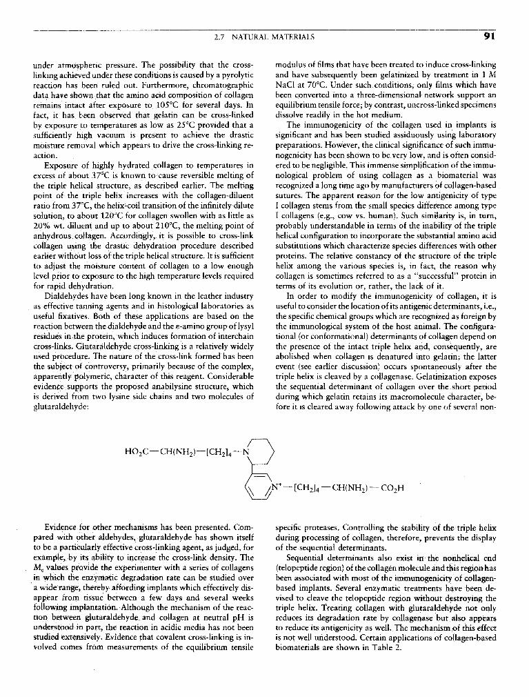
2.7 NATURAL MATERIALS 91
under atmospheric pressure. The possibility that the cross- modulus of films that have been treated to induce cross-linkinglinking achieved under these conditions is caused by a pyrolytic and have subsequently been gelatinized by treatment in 1 Mreaction has been ruled out. Furthermore, chromatographic NaCl at 70°C. Under such conditions, only films which havedata have shown that the amino acid composition of collagen been converted into a three-dimensional network support anremains intact after exposure to 105°C for several days. In equilibrium tensile force; by contrast, uncross-linked specimensfact, it has been observed that gelatin can be cross-linked dissolve readily in the hot medium.by exposure to temperatures as low as 25°C provided that a The immunogenicity of the collagen used in implants issufficiently high vacuum is present to achieve the drastic significant and has been studied assiduously using laboratorymoisture removal which appears to drive the cross-linking re- preparations. However, the clinical significance of such immu-action. nogenicity has been shown to be very low, and is often consid-
Exposure of highly hydrated collagen to temperatures in ered to be negligible. This immense simplification of the immu-excess of about 37°C is known to cause reversible melting of nological problem of using collagen as a biomaterial wasthe triple helical structure, as described earlier. The melting recognized a long time ago by manufacturers of collagen-basedpoint of the triple helix increases with the collagen-diluent sutures. The apparent reason for the low antigenicity of typeratio from 37°C, the helix-coil transition of the infinitely dilute I collagen stems from the small species difference among typesolution, to about 120°C for collagen swollen with as little as I collagens (e.g., cow vs. human). Such similarity is, in turn,20% wt. diluent and up to about 210°C, the melting point of probably understandable in terms of the inability of the tripleanhydrous collagen. Accordingly, it is possible to cross-link helical configuration to incorporate the substantial amino acidcollagen using the drastic dehydration procedure described substitutions which characterize species differences with otherearlier without loss of the triple helical structure. It is sufficient proteins. The relative constancy of the structure of the tripleto adjust the moisture content of collagen to a low enough helix among the various species is, in fact, the reason whylevel prior to exposure to the high temperature levels required collagen is sometimes referred to as a "successful" protein infor rapid dehydration. terms of its evolution or, rather, the lack of it.
Dialdehydes have been long known in the leather industry In order to modify the immunogenicity of collagen, it isas effective tanning agents and in histological laboratories as useful to consider the location of its antigenic determinants, i.e.,useful fixatives. Both of these applications are based on the the specific chemical groups which are recognized as foreign byreaction between the dialdehyde and the e-amino group of lysyl the immunological system of the host animal. The configura-residues in the protein, which induces formation of interchain tional (or conformational) determinants of collagen depend oncross-links. Glutaraldehyde cross-linking is a relatively widely the presence of the intact triple helix and, consequently, areused procedure. The nature of the cross-link formed has been abolished when collagen is denatured into gelatin; the latterthe subject of controversy, primarily because of the complex, event (see earlier discussion) occurs spontaneously after theapparently polymeric, character of this reagent. Considerable triple helix is cleaved by a collagenase. Gelatinization exposesevidence supports the proposed anabilysine structure, which the sequential determinant of collagen over the short periodis derived from two lysine side chains and two molecules of during which gelatin retains its macromolecule character, be-glutaraldehyde: fore it is cleared away following attack by one of several non-
Evidence for other mechanisms has been presented. Com- specific proteases. Controlling the stability of the triple helixpared with other aldehydes, glutaraldehyde has shown itself during processing of collagen, therefore, prevents the displayto be a particularly effective cross-linking agent, as judged, for of the sequential determinants.example, by its ability to increase the cross-link density. The Sequential determinants also exist in the nonhelical endMc values provide the experimenter with a series of collagens (telopeptide region) of the collagen molecule and this region hasin which the enzymatic degradation rate can be studied over been associated with most of the immunogenicity of collagen-a wide range, thereby affording implants which effectively dis- based implants. Several enzymatic treatments have been de-appear from tissue between a few days and several weeks vised to cleave the telopeptide region without destroying thefollowing implantation. Although the mechanism of the reac- triple helix. Treating collagen with glutaraldehyde not onlytion between glutaraldehyde and collagen at neutral pH is reduces its degradation rate by collagenase but also appearsunderstood in part, the reaction in acidic media has not been to reduce its antigenicity as well. The mechanism of this effectstudied extensively. Evidence that covalent cross-linking is in- is not well understood. Certain applications of collagen-basedvolved comes from measurements of the equilibrium tensile biomaterials are shown in Table 2.

92 2 CLASSES OF MATERIALS USED IN MEDICINE
TABLE 2 Certain Applications of Collagen-Based being hyaluronidase. These enzymes are primarily responsibleBiomaterials for the physiological turnover rate of GAGs, which is in the
—' 1 1 1 i range o f 2—14 days.Application Physical state The nature of the oligosaccharide link appears to be identi-
^ ̂ ̂ GAGs, except for keratan sulfate, and is a galacto-Sutures Extruded tape (Schmitt, 1985) syl-galactosyl-xylose, with the latter glycosidically linked toHemostatic agents Powder, sponge, fleece (Stengel et the hydroxyl group of serine in the protein core.
al, 1974; Chvapil, 1979) The very high molecular weight of hyaluronic acid is theBlood vessels Extruded collagen tube, processed basis of most uses of this GAG as a biomaterial: almost all
human or animal blood vessel applications make use of the exceptionally high viscosity and(Nimni, 1988) the facility to form gels which characterize this polysaccharide.
Heart valves Processed porcine heart valve Hyaluronic acid gels have found considerable use in ophthal-(Nimni, 1988) mology because they facilitate cataract surgery as well as retinal
Tendon, ligaments Processed tendon (Piez, 1985) reattachment. Other uses of this GAG reported are the treat-Burn treatment (dermal re- Porous cotlagen-glycosammoglycan ment of Degenerative joint dysfunction in horses and experi-
generation) (GAG) polymer3 (Yannas et al, mental treatment of certain orthopedic dysfunctions in hu-1981, 1982, and 1989) mans. On the other hand, sulfated GAGs are anionically
Peripheral nerve regeneration Porous collagen-GAG copolymer charged and can induce precipitation of collagen at acidic PH(Chang and Yannas, 1992) levels, a process which yields collagen—GAG coprecipitates
Meniscus regeneration Porous collagen-GAG copolymers thf fn be subsequently freeze dried and covalently cross-(Stone et al 1989) linked to yield biomaterials which have been shown capable
. . . . , . i c n °f inducing regeneration of skin (dermis), peripheral nerve,Intradermal augmentation Iniectable suspension o r collagen , . . , . . ,~-, . t 1 » rparticles (Piez, 1985) and the meniscus of Joints (Table I ) .
Gynecological applications Sponges (Chvapil, 1979)
Drug-deliver)7 systems Various forms (Stenzel et a/., 1974, _. «M™»|Chvapil, 1979) UAbTIN
"See also Chapter 7.10. Elastin is the least soluble protein in the body, consistingas it does of a three-dimensional cross-linked network. It can beextracted from tissues by dissolving and degrading all adjacentsubstances. It appears to be highly amorphous and thus eludeselucidation of its structure by crystaUographic methods. Fortu-
PROTEOGLYCANS AND GLYCOSAMINOGLYCANS nately, it exhibits ideal rubber elasticity and it thus becomespossible to study certain features of the macromolecular net-
f^, . , //-^ A ̂ \ n 1 1 work. Fo r example, mechanical measurements have shownGlycosammoglycans (GAGs) occur naturally as polysaccha- , , \ t • i • i
• i t . i e i - - i • i i tnat the average number of ammo acid units between cross-ride branches of a protein chain, or protein core, to which they . . . . _. QA T 1 11 1 • 1 1 1 1
, , , , - .c i - i - j i - i "ri links is 71—84. Insoluble elastic preparations can be degradedare covalently attached via a specific oligosaccharide link. The , , , , , , ,r, . t , •
, , , , 1 t _ - u L L j - L J by the enzyme elastase but the soluble preparations made thisentire branched macromolecule, which has been described as , , , . , , . . .t • <it t i i „ £ • - i i way have not yet been used extensively as biomaterials.having a bottle brush configuration, is known as a proteogly-can and has a molecular weight of about 103 kDa.
The structure of GAGs can be generically described as thatof an alternating copolymer, the repeat unit consisting of a GRAIT COPOLYMERS Of COLLAGENhexosamine (giucosamine or galactosamine) and of another AND GLYCOSAMINOGLYCANSsugar (galactose, glucuronic acid or iduronic acid). IndividualGAG chains are known to contain occasional substitutions The preceding discussion has focused on the individual mac-of one uronic acid for another; however, the nature of the romolecular components of ECM. By contrast, naturally occur-hexosamine component remains invariant along the chain. ring ECMs are insoluble networks comprising several macro-There are other deviations from the model of a flawless alternat- molecular components. Several types of ECMs are known toing copolymer, such as variations in sulfate content along the play critical roles during organ development. During the pastchain. It is, nevertheless, useful for the purpose of getting ac- several years certain analogs of ECMs have been synthesizedquainted with the GAGs to show their typical (rather, typified) and have been studied as implants. This section summarizes therepeat unit structure, as in Fig. 4. The molecular weights of evidence for the unusual biological activity of a small number ofGAGs are in the range of 5—60 kDa, with the exception of ECM analogs.hyaluronk acid, the only GAG which is not sulfated; it exhibits In the 1970s it was discovered that a highly porous graftmolecular weights in the range of 50-500 kDa. Sugar units copolymer of type I collagen and chondroitin 6-sulfate wasalong GAG chains are linked by a or (3 glycosidic bonds and capable of modifying dramatically the kinetics and mechanismare 1, 3, or 1, 4 (Fig. 4). There are several naturally occurring of healing of full-thickness skin wounds in rodents (Yannas etenzymes which degrade specific GAGs, the most well-known al., 1977). In the adult mammal, full-thickness skin wounds

2.7 NATURAL MATERIALS 93
FIG. 4. Repeat units of glycosaminoglycans. (Reprinted for J. E. Siebert, 1987, with permission.)
represent areas that are demonstrably devoid of both epidermis the copolymer (Yannas et al., 1981, 1982). The copolymerand dermis, the outer and inner layers of skin, respectively. underwent substantial degradation under the action of tissueSuch wounds normally close by contraction of wound edges collagenases during the 3-week period, at the end of which itand by synthesis of scar tissue. Previously, collagen and various had degraded completely at the wound site. Studies of theglycosaminoglycans, each prepared in various forms such as connective tissue synthesized in place of the degraded copoly-powder and films, had been used to cover such deep wounds mer eventually showed that the new tissue was distinctly differ-without observing a significant modification in the outcome ent from scar and was very similar, though not identical, toof the wound healing process (compare the historical review physiological dermis. In particular, new hair follicles and newof Schmitt, 1985). sweat glands had not been synthesized. This marked the first
Surprisingly, grafting of these wounds with the porous CG instance where scar synthesis was blocked in a full-thicknesscopolymer on guinea pig wounds blocked the onset of wound skin wound of an adult mammal and, in its place, a physiologi-contraction by several days and led to synthesis of new connec- cal dermis had been synthesized. That this result was not con-tive tissue within about 3 weeks in the space occupied by fined to guinea pigs was confirmed by grafting the same copoly-

94 2 CLASSES OF MATERIALS USED IN MEDICINE
mer on full-thickness skin wounds in other adult mammals, Schmitt, F. O. (1985). Adventures in molecular biology, Ann. Rev.including pigs (Butler et al, 1995) and, most importantly, Biophys. Biophys. Chem. 14: 1-22,human victims of massive burns (Burke et al., 1981). Silbert' J- E- <1987)- Advances in the biochemistry of proteoglycam.
Although a large number of CG copolymers were synthe- in Connective Tissue Disease, J. Uitto and A. J. Perejda, eds. Marcel. , , , . , t u j u i Dekker, New York, Ch. 4, pp. 83-98.
sized and studied as grafts, it was observed that only one g R and Rubin, A. L. (1974). Collagen as apossessed the requisite activity to modify dramatically the biomaterial. in Annual Review of Biophys and Bioengineering,wound healing process in skin. The structure of the CG copoly- L j MuilinS) ed>j Annua[ Reviews Inc., Palo Alto, CA, Vol. 3,mer required specification at two scales: at the nanoscale, the pp 231-252.average molecular weight of the cross-linked network which Stone, K. R., Rodkey, W. G., Webber, R. J., McKinney, L., and Stead-was required to induce regeneration of the dermis was de- man, J.R. (1990). Collagen-based prostheses for meniscal regenera-scribed by an average molecular weight between cross-links of tion. Clin. Orth. 252: 129-135.12,500 ± 5,000; at the microscale, the average pore diameter Yannas, I. V. (1972). Collagen and gelatin in the solid state. /. Macro-was between 20 and 120 fua. Relatively small deviations from moL Sci.-Revs. Macromol. Chem., C7(l), 49-104.
these structural features, either at the nanoscale or the micro- Yannas; J- V" Burke' J' F" G<f fon' P" L"> and "uang' Cf' (1977)"
, , i , f • • ,,7 • .,r»on\ T • £ Multilayer membrane useful as synthetic skin. U.S. Patentscale, led to loss of activity (Yannas et al., 1989). In view of ' 'the nature of its unique activity this biologically active macro- Yann'as> \ yj g^ j' K) Warpehoskl5 MM Stasikeiis, P., Skrabut,molecular network has been referred to as skin regeneration E M-> OrgU1> D. P>> and Giard> D> j, (1981). Promptj iong.term
template (SRT). (See also Chapter 7.10.) functional replacement of skin. Trans. Am. Soc, Artif. Intern. Or-The regeneration of dermis was followed by regeneration gans 27: 19-22.
of a quite different organ, the peripheral nerve (Yannas et al., Yannas, I. V., Burke, J. F., Orgill, D. P., and Skrabut, E. M. (1982).1987; Chang and Yannas, 1992). This was accomplished using Wound tissue can utilize a polymeric template to synthesize a func-a distinctly different ECM analog, termed nerve regeneration tlonal extension of skin. Science 215: 174-176.template (NRT). Although the chemical composition of the Yannas, I. V., Orgill, D. P., Silver, J., Norregaard, T. V,, Zervas,two templates was identical there were significant differences R T" and Schoene> W" C- (1987). Regeneration of sciatic nerve
* i r Mr>T j j - j ui i across 15 mm gap by use of a polymeric template, in Advances inm other structural features. NRI degrades considerably slower „. . - i n i / - / - / - i i - j ™ XT v i
1 ^.-.T- , i ,- i /• XTT.T i i -, i Biomedtcal Polymers, C. G. Gebelemi, ed. Plenum, New York,than SRT (about 6 weeks ror NR i compared to about 2 weeks 1 «for SRT) and is also characterized by a much smaller average yj^ L ̂ , ee? E>> Orgill) D. Pt> skrabut> E. M>> and Murphy,pore diameter (about 5 ^m compared to 20-120 fj,m for SRT). G. F. (1989). Synthesis and characterization of a model extracellularA third ECM analog was shown to induce regeneration of the matrix that induces partial regeneration of adult mammalian skin.knee meniscus in the dog (Stone et al, 1990). The combined Proc. Natl. Acad. Set. U.S.A. 86: 933-937.findings showed that the activity of individual ECM analogswas organ specific. It also suggested that other ECM analogs,still to be discovered, could induce regeneration of organs suchas a kidney or the pancreas. _ _ _
2.8 COMPOSITES.... ,. Harold AlexanderBibliography
Burke, J. F., Yannas, I. V., Quinby, W. C., Jr., Bondoc, C. C., and The word "composite" means "consisting of two or moreJung, W. K. (1981). Successful use of a physiologically acceptable distinct parts." At the atomic level, materials such as metalartificial skin in the treatment of extensive burn injury. Ann. Surg. alloys and polymeric materials could be called composite mate-194: 413-428. rials in tnat they consist of different and distinct atomic group-
Butler, C, E., Compton, C. C., Yannas, I. V., and Orgill, D. P. (1995). ings At the micrOstructural level (about 10~4 to 10~2 cm), aThe effect of keratinocytc seeding of collagen-glycosammoglycan metaj ̂ such ̂ & plain.carbon sted containing ferrite andmembranes on the regeneration of skin in a porcine model. 27th ,. , , , „ , . . , . , ,. I * , t i A D A • A I L pearlite could be called a composite material since the ferriteAnnual Meeting of the American Burn Association, Albuquerque, . .. \ - - \ - - \ \NM April 19-21 a pearlite are distinctly visible constituents as observed in
Chang, A. S., and Yannas, I. V. (1992). Peripheral nerve regeneration. the °Ptical microscope. At the molecular and rnicrostructuralin Encyclopedia of Neurosdence, B. Smith and G. Adelman, eds., level> tissues such as bone and tendon are certainly compositesBirkhauser, Boston. Suppl. 2, pp. 125-126. with a number of levels of hierarchy.
Chvapil, M. (1979). Industrial uses of collagen, in Fibrous Proteins: In engineering design, a composite material usually refers toScientific, Industrial and Medical Aspects, D. A. D. Parry and a material consisting of constituents in the micro- to macrosizeL. K. Creamer, eds., Academic Press, London, vol. 1, pp. 247-269. range5 favoring the macrosize range. For the purpose of discus-
Davidson, J. M. (1987). Elastin, structure and biology, in Connective sion in this chapter, composites can be considered to be materi-TissueDtseas^ J Uitto and A. J. Perejda, eds. Marcel Dekker, ^ comisti of two or more chemicany distinct constituents,New York, Ch. 2 pp. 29-54. , , ,. . . !, . ,
v w' /taca\ c f ^ u i • on a rnacroscale, having a distinct interface separating them.Kauzmann, W. (1959). Some factors m the interpretation of protein _ , . , - . . „, . ,denaturation, Adv. Protein Chem. 14: 1-63. ^^ definition encompasses the fiber and paniculate composite
Nimni, M. E., ed. (1988). Collagen, Vol III, Biotechnology. CRC materials of primary interest as biomatenals. Such compositesPress, Boca Raton, FL. consist of one or more discontinuous phases embedded within
Piez, K. A. (1985). Collagen, in Encyclopedia of Polymer Science and a continuous phase. The discontinuous phase is usually harderTechnology 3: 699-727. and stronger than the continuous phase and is called the rein-

C H A P T E R
6Degradation of Materials in the
Biological EnvironmentARTHUR J. COURY, ROBERT J. LEVY, CARL R. McMiixiN, YASHWANT PATHAK, BUDDY D. RATNER,
FREDERICK J. SCHOEN, DAVID F. WILLIAMS, AND RACHEL L. WILLIAMS
6 1 INTRODUCTION quence of the severity of the biological environment. ImplantD j j ri D * materials can solubilize, crumble, become rubbery, or becomeBuddy D. Ratner . ., . , , ' ' . . "
rigid with time. The products of degradation may be toxicto the body, or they may be designed to perform a pharmaco-
The biological environment is surprisingly harsh and can logk function. Degradation is seen with metals, polymers,lead to rapid or gradual breakdown of many materials. Super- ceramics, and composites. Thus, biodegradation as a subjectficially, one might think that the neutral PH, low salt content, fe broad m SCQp^ and rightfully should command consider-and modest temperature of the body would constitute a mild aWe attention for the biomaterials scientist. This sectionenvironment. However, many special mechanisms are brought introduces biodegradation issues for a number of classes ofto bear on implants to break them down. These are mechanisms materiaiS5 and provides a basis for further study on thisthat have evolved over millennia specifically to rid the living complex but critical subject,organism of invading foreign substances and they now attackcontemporary biomaterials.
First, consider that, along with the continuous or cyclic * j fi«MM~AI Akin RirwuEMir AIstress many biomaterials are exposed to, abrasion and flexure °** -̂"twll*-'u- ™U WWWIMMUU.may also take place. This occurs in an aqueous, ionic environ- DEGRADATION Of POLYMERSment that can be electrochemically active to metals and plasti- Arthur J. Cowrycizing (softening) to polymers. Then, specific biological mecha-nisms are invoked. Proteins adsorb to the material and can Biodegradation is the chemical breakdown of materials byenhance the corrosion rate of metals. Cells secrete powerful tne action of living organisms which leads to changes in physi-oxidizing agents and enzymes that are directed at digesting cal properties. It is a concept of vast scope, ranging fromthe material. The potent degradative agents are concentrated decomposition of environmental waste involving microorgan-between the cell and the material where they act, undiluted by isms to host-induced deterioration of biomaterials in implantedthe surrounding aqueous medium. medical devices. Yet it is a precise term, implying that specific
To understand the biological degradation of implant materi- biological processes are required to effect such changes (Wil-als, synergistic pathways should be considered. For example, iiams> 1939). This chapter, while grounded in biodegradation,the cracks associated with stress crazing open up fresh surface addresses other processes that contribute to the often complexarea to reaction. Swelling and water uptake can similarly in- mechanisms of polymer degradation. Its focus is the unintendedcrease the number of sites for reaction. Degradation products chemical breakdown, in the body, of synthetic solid-phase poly-can alter the local pH, stimulating further reaction. Hydrolysis mers, (See Chapter 2.5 for a description of systems engineeredof polymers can generate more hydrophilic species, leading to to break down in the body.)polymer swelling and entry of degrading species into the bulkof the polymer. Cracks might also serve as sites for the initiationof calcification.
Biodegradation is a term that is used in many contexts. It POLYMER DEGRADATION PROCESSEScan be used for reactions that occur over minutes or over years.It can be engineered to happen at a specific time after Polymeric components of implantable devices are generallyimplantation, or it can be an unexpected long-term conse- reliable for their intended lifetimes. Careful selection and exten-
Btomaterials Science— . « Copyright €> 1996 by Academic Press, Inc.£-*r J All rights of reproduction in any form reserved.

244 6 DEGRADATION OF MATERIALS IN THE BIOLOGICAL ENVIRONMENT
TABLE I Typical Operations on an Injection-Moldable dimensional and mechanical property changes (Coury et aL,Polymer Biomaterial 1988). On the surface, a powerful acute attack by ceils and
— many chemical agents, including enzymes, will have beenPolymer: Synthesis, extrusion, palletizing substantially withstood. With the resolution of this acutePellets: Packaging, storage, transfer, drying inflammatory phase, a fibrous capsule will likely have formed., t - u- i j c - u - i • • over the device, and the rate of release of powerful chemicalsComponents: Injection molding, post-mold finishing, cleaning, in- , - i n •» i . n . i
specting, packaging, storage from activated cells will have markedly decreased.For those polymers subjected to chemical degradation in
Device: Fabrication, storage (prestenhzation), cleaning, inspecting, • c -c L L - I J - L J U, ' f j. ... . , ., . r- vivo, few it any reports have comprehensively described thepackaging, storage (packaged), sterilization, storage (sterile), ship- . . r .. , . . .meat, storage (preimplant), implantation, operation in body multistep processes and interactions that comprise each mecha-^ nism. Rather, explant analysis and occasionally metabolite
evaluation is used to infer reaction pathways. The analysis ofchemically degraded polymers has almost always implicatedeither hydrolysis or oxidation as an essential component ofthe process.
sive preclinical testing of the compositions, fabricated compo-nents, and devices usually establish functionality and durabil-ity. However, with chronic, indwelling devices, it is infeasibleduring qualification to match all implant conditions in real HYDROLYTIC BIODEGRADATIONtime for years or decades of use. The accelerated aging, animalimplants, and statistical projections employed cannot expose StmctiiKS of Hydrofyz^ble Polymersall of the variables which may cause premature deteriorationof performance. The ultimate measure of the acceptability of a Hydrolysis is the scission of susceptible molecular functionalmaterial for a medical device is its functionality for the device's groups by reaction with water. It may be catalyzed by acids,intended lifetime as ascertained in human postimplant surveil- bases, salts, or enzymes. It is a single-step process in which thelance. rate of chain scission is directly proportional to the rate of
No polymer is totally impervious to the chemical processes initiation of the reaction (Schnabel, 1981). A polymer's suscep-and mechanical action of the body. Generally, polymeric bio- tibility to hydrolysis is the result of its chemical structure, itsmaterials degrade because body constituents attack the bioma- morphology, its dimensions, and the body's environment,terials directly or through other device components or the In a commonly used category of hydrolyzable polymericintervention of external factors.
Numerous operations are performed on a polymer fromthe time of its synthesis to its use in the body (see, e.g., TADIT •» \/c u T j r\ j_ . . . . „ , , . , , . . . . . . . , , , . , TABLE 2 Mechanisms Leading t o DegradationTable 1). Table 2 lists mechanisms of physical and chemical c „ , „ • a, . . , . , i - . of Polymer Properties0
deterioration, which may occur alone or in concert at various Istages of a polymer's history. Moreover, a material's treat- Physical Ch mi 1ment prior to implant may predispose it to stable or unstable _end-use behavior (Brauman et al., 1981; Greisser et al., Sorption Thermolysis1994). A prominent example of biomaterial degradation r ,, Radical scissioncaused by preimplant processing is the gamma irradiation . Depolymerizationsterilization of ultrahigh-molecular-weight polyethylene used ° temn8 Oxidationin total joint prostheses. The process generates free radicals Dissolution Chemicalwithin the material which react with oxygen to produce Mineralization Thermooxidativeundesirable oxidation products. Chain oxidation and scission Extraction Solvolysiscan occur for periods of months to years, causing loss of Crystallization Hydrolysisstrength and embrittlement with limited shelf life (McKellop n Alcoholysiset al., 1995; Furman and Li, 1995; Weaver et al, 1995). Decrystalhzation AmmoiysiS) etc
It is crucially important, therefore, that appropriate and Stress crackmg Photolysisrigorous processing and characterization protocols be fol- Fatigue fracture Visiblelowed for all operations (Coury et al., 1988). Impact fracture Ultraviolet
After a device has been implanted, adsorption and absorp- Radiolysistion processes occur. Polymeric surfaces in contact with Gamma raysbody fluids immediately adsorb proteinaceous components, X-raysand the bulk begins to absorb soluble components such as Electron beamwater, proteins, and lipids. Cellular elements subsequently Fracture-induced radical reactionsattach to the surfaces and initiate chemical processes. Withbiostable components, this complex interplay of factors is "Some degradation processes may involve combina-of little functional consequence. At equilibrium fluid absorp- tions of two or more individual mechanisms,tion, there may be some polymer plasticization, causing

6.2 CHEMICAL AND BIOCHEMICAL DEGRADATION OF POLYMERS 245
0 0II B,0 II
— C — X— — > —C-OH + HX— 0(H*,OH, or enzyme) u+ p
—0—CH2—0— > —OH 4 C + HO—X - °>NH'S Q Acetal H2Q / \
Examples: Amide = —C-NH—HO nH HO
0 I o °H H+ .A -OH
^ ' -- ^^ — ̂ ^Vc, "°Hemiacetal I
0 0 HII H20 II H+
—X — C — X'— > —X—C-OH + HX'— — CH2—0—CH2— » —CH2OH •»• HOCH2—(H*,OH7 or enzyme) Ether H20
X = O.NH.S * \lX' = 0,NH,S ' H+ or OH 2H20
—XH + C02 + HX'— j > 1 * [
H C = N 2 C = 0 C=0Examples: Urethane = —NH-C-Q— Nitrile j I
0 NH2
Urea = —NH-C-NH— * NH*OH
5 oM H O i !Carbonate = 0-C-O —RQ—p—QR,— 2 ^ —RQH + H0_p—OH + HOR,—
| H+ or OH" |
1 J H20 J 8 PhospSo'nate—C—X—C— — » —C-OH + HX —C —
(H*,OH, or enzyme)CN CN CN CN
X - O.NH.S i | H,0 I I0 0 —CH,—C—CH2—C— »• —CH2—C—CH2OH + HC—I I I I 2 | 2 | OH" I I
Examples: Imide = —C-NH-C-— C = 0 C = 0 C = 0 C = 00 0 | | | |II 11 OR OR OR OR
Anhydride = —C-O-C— Polycyanoacrylate
FIG. 1. Hydrolyzable groups in polymer biomaterials.
biomaterials, functional groups consist of carbonyls bonded „ _,. Hydrocarbonto heterochain elements (O, N, S). Examples include esters, 2 |amides, and carbonates (Fig. 1). Other polymers containing Rgroups such as ether, acetal, nitrile, phosphonate, or active R=H? Alky l , Aryl Examples: Polyethylenemethylenes, hydrolyze under certain conditions (Fig. 1). PolypropyleneGroups that are normally very stable to hydrolysis are indicatedin Fig. 2.
The rate of hydrolysis tends to increase with a high proper- —cxz—cx/z— Halocarbontion of hydrolyzabie groups in the main or side chain, other X = F > C1) H Examples: Polytetrafluoroethylenepolar groups which enhance hydrophilicity, low crystallinity, X ' = F , Cl Polychlorotrifluoroethylenei r -ui r i A •*, u- u • r j Polyvinylidine chloridelow or negligible cross-link density, a high ratio of exposedsurface area to volume and, very likely, mechanical stress.Porous hydrolyzabie structures undergo especially rapid prop- ^erty loss because of their large surface area. Factors that tend SiO Dimethyls i loxaneto suppress hydrolysis kinetics include hydrophobic moieties |(e.g., hydrocarbon or fluorocarbon), cross-linking, high crystal- 3
linity due to chain order, thermal annealing or orientation,low stress, and compact shape. While the molecular weight of °linear polymers per se may not have a great effect on degrada- $ Sul fonetion rate, physical property losses may be retarded for a given IInumber of chain cleavage events with relatively high-molecu- °lar-weight polymers. Property loss caused by chain cleavage FIG. 2. Groups highly stable to hydrolysis.

246 6 DEGRADATION OF MATERIALS IN THE BIOLOGICAL ENVIRONMENT
is more pronounced in polymers with weak intermolecular of the enzyme and the biopolymer substrate which result inbonding forces, enhanced bond cleavage rates. Lacking the recognition se-
quences of susceptible natural polymers, most synthetic poly-mers are more resistant to enzymatic degradation. Neverthe-less, comparative studies have shown some enhancement of
Host-Induced Hydrolytic Processes hydrolysis rates by enzymes, particularly with synthetic polyes-ters and polyamides (Zaikov, 1985; Smith et al., 1987; Ko-
The body is normally a highly controlled reaction medium. pecek et ̂ 1983) Apparently the enzymes can recognize andThrough homeostasis, the normal environment of most im- interact with structural segments of the polymers, or moreplants is maintained at isothermal (37°C), neutral (pH 7.4), accurately, of the polymers coated with serum proteins, toaseptic, and photoprotected aqueous steady state. By in vitro initiate their catalytic action in vivo (Pitt, 1992).standards, these conditions appear mild. However, complex Enzymes with demonstrated effects on hydrolysis rates caninteractions of humoral and cellular components of body be quite selective in the presence of several hydrolyzable func-fluids involving activators, receptors, inhibitors, etc. produce tional groups. For example, polyether urethane ureas and poly-aggressive responses to any foreign bodies through the pro- ester urethane ureas exposed to hydrolytic enzymes (an ester-cesses of adhesion, chemical reaction, and paniculate ase, cholesterol esterase, and a protease, elastase) weretransport. observed for rate and site of hydrolysis. Enzyme catalysis was
Several scenarios leading to hydrolysis in the host can be clearly observed for the ester groups while the hydrolyticallyconsidered. First, essentially neutral water is capable of hydro- susceptible urea, urethane, and ether groups did not showlyzing certain polymers (e.g., polyglycolic acid) at a significant significant hydrolysis as indicated by release of radiolabeledrate (Chapter 2.5 and Zaikov, 1985). However, this simple degradation products (Santerre et ai, 1994; Labow et aL,mechanism is unlikely to be significant in polymer compositions 1995).selected for long-term in vivo biostability. Many enzymes exert predominantly a surface effect because
Next, ion-catalyzed hydrolysis offers a likely scenario in of their great molecular size, which prevents absorption. Evenbody fluids. Extracellular fluids contain ions such as: H+, OH~, hydrogels [e.g., poly(acrylamide)], which are capable of ab-Na+, Cl~, HCO^jPO^3, K+ Mg2+, Ca2+ and SO;j~. Organic sorbing certain proteins, have molecular weight cutoffs foracids, proteins, lipids, lipoproteins, etc. also circulate as absorption well below those of such enzymes. However, as thesoluble or colloidal components. It has been shown that degrading surface becomes roughened or fragmented, enzy-certain ions (e.g., PO^) are effective hydrolysis catalysts, matic action may be enhanced as a result of increased surfaceenhancing, for example, reaction rates of polyesters by several area if the substrates remain accessible to phagocytic cells thatorders of magnitude (Zaikov, 1985). Ion catalysis may be contain the active enzymes. Implanted devices that are in con-a surface effect or a combined surface-bulk effect, depending tinuous motion relative to neighboring tissue can provoke in-on the hydrophilicity of the polymer. Very hydrophobic flammation, stimulating enzyme release,polymers (e.g., those containing <2% water of saturation)absorb negligible concentrations of ions. Hydrogels, on theother hand, which can absorb large amounts of water (>15%by weight) are essentially "sieves," allowing significant levels Hydrolysis: Precllnlcul and Clinical Experienceof ions to be absorbed with consequent bulk hydrolysis via ,. .acid, base, or salt catalysis. A discu^on of m vivo responses of several prominent poly-
Localized pH changes in the vicinity of the implanted device, "«* Compositions known to be susceptible to hydrolysis fol-which usually occur during acute inflammation or infection, lows. The structures of these polymers are described in Chap-
can cause catalytic rate enhancement of hydrolysis (Zaikov, er ' "1985). Organic components, such as lipoproteins, circulatingin the bloodstream or in extracellular fluid, appear to be capa-ble of transporting catalytic inorganic ions into the polymer *bulk by poorly defined mechanisms. Poly(ethylene terephthalate) (PET), in woven, velour, or
Enzymes generally serve a classic catalytic function, altering knitted fiber configurations, remains a primary choice ofreaction rate (via ion or charge transfer) without being con- cardiovascular surgeons for large-diameter vascular prosthe-sumed, by modifying activation energy but not thermodynamic ses, arterial patches, valve sewing rings, etc. It is a strong,equilibrium. While enzymes function in extracellular fluids, flexible, polymer, stabilized by high crystallinity as a resultthey are most effectively transferred onto target substrates by of chain rigidity and orientation and is often considered todirect cell contact (e.g., during phagocytosis). Hydrolytic en- be biostable. Yet, over several decades, there have beenzymes or hydrolases (e.g., proteases, esterases, lipases, glycosi- numerous reports of long-term degeneration of devices indases) are named for the molecular structures they affect. They vivo, owing to breakage of fibers and device dilation. Theare cell-derived proteins which act as highly specific catalysts proposed causes have been structural defects, processingfor the scission of water-labile functional groups. techniques, handling procedures, and hydrolytic degradation
Enzymes contain molecular chain structures and develop (Cardia et aL, 1989).conformations that allow "recognition" of chain sequences Systematic studies of PET implants in healthy dogs have(receptors) on biopolymers. Complexes form between segments shown slow degradation rates, which were estimated to be
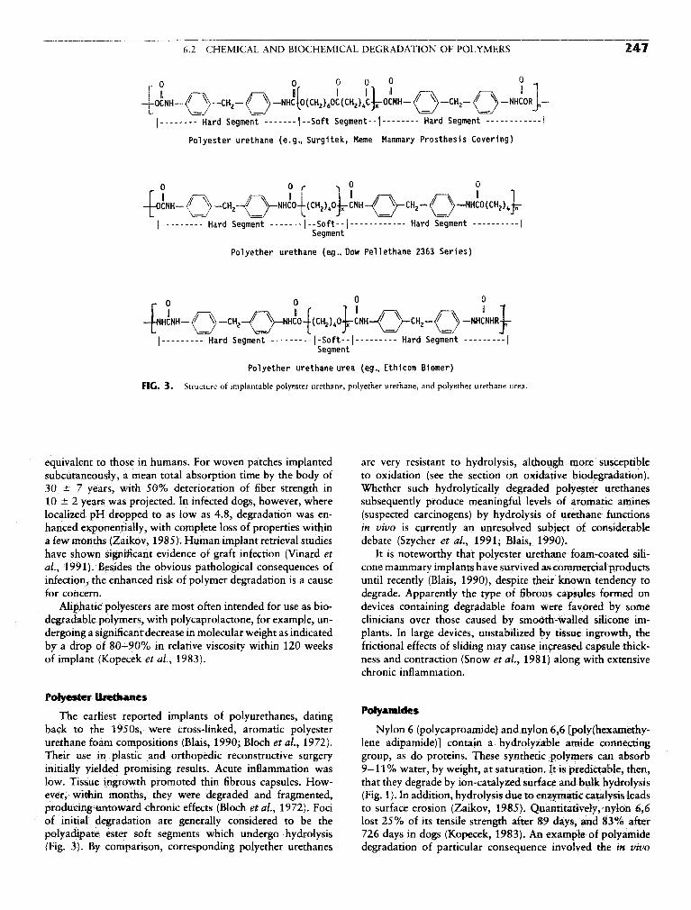
6.2 CHEMICAL AND BIOCHEMICAL DEGRADATION OF POLYMERS 247
Polyether urethane urea (eg., Ethicon Biomer)
FIG. 3. Structure of implantable polyester urethane, polyether urethane, and polyether urethane urea.
equivalent to those in humans. For woven patches implanted are very resistant to hydrolysis, although more susceptiblesubcutaneously, a mean total absorption time by the body of to oxidation (see the section on oxidative biodegradation).30 ± 7 years, with 50% deterioration of fiber strength in Whether such hydrolytically degraded polyester urethanes10 ± 2 years was projected. In infected dogs, however, where subsequently produce meaningful levels of aromatic amineslocalized pH dropped to as low as 4.8, degradation was en- (suspected carcinogens) by hydrolysis of urethane functionshanced exponentially, with complete loss of properties within in vivo is currently an unresolved subject of considerablea few months (Zaikov, 1985). Human implant retrieval studies debate (Szycher et al., 1991; Blais, 1990).have shown significant evidence of graft infection (Vinard et It is noteworthy that polyester urethane foam-coated sili-ai, 1991). Besides the obvious pathological consequences of cone mammary implants have survived as commercial productsinfection, the enhanced risk of polymer degradation is a cause until recently (Blais, 1990), despite their known tendency tofor concern. degrade. Apparently the type of fibrous capsules formed on
Aliphatic polyesters are most often intended for use as bio- devices containing degradable foam were favored by somedegradable polymers, with polycaprolactone, for example, un- clinicians over those caused by smooth-walled silicone im-dergoing a significant decrease in molecular weight as indicated plants. In large devices, unstabilized by tissue ingrowth, theby a drop of 80—90% in relative viscosity within 120 weeks frictional effects of sliding may cause increased capsule thick-of implant (Kopecek et al., 1983). ness and contraction (Snow et al., 1981) along with extensive
chronic inflammation.
Polyester Urethanes
The earliest reported implants of polyurethanes, dating ^back to the 1950s, were cross-linked, aromatic polyester Nylon 6 (polycaproamide) and nylon 6,6 [poly(hexamethy-urethane foam compositions (Blais, 1990; Bloch et al., 1972). lene adipamide)] contain a hydrolyzable amide connectingTheir use in plastic and orthopedic reconstructive surgery group, as do proteins. These synthetic polymers can absorbinitially yielded promising results. Acute inflammation was 9—11% water, by weight, at saturation. It is predictable, then,low. Tissue ingrowth promoted thin fibrous capsules. How- that they degrade by ion-catalyzed surface and bulk hydrolysisever, within months, they were degraded and fragmented, (Fig. 1). In addition, hydrolysis due to enzymatic catalysis leadsproducing untoward chronic effects (Bloch et al., 1972). Foci to surface erosion (Zaikov, 1985). Quantitatively, nylon 6,6of initial degradation are generally considered to be the lost 25% of its tensile strength after 89 days, and 83% afterpolyadipate ester soft segments which undergo hydrolysis 726 days in dogs (Kopecek, 1983). An example of polyamide(Fig. 3). By comparison, corresponding polyether urethanes degradation of particular consequence involved the in vivo

248 6 DEGRADATION OF MATERIALS IN THE BIOLOGICAL ENVIRONMENT
FIG. 4. Proposed homolytic chain reaction and heterolytic oxidation mechanisms.
fragmentation of the nylon 6 tail string of an intrauterine way for bacteria to travel from the vagina into the uterus,contraceptive device. This string consisted of nylon 6-coated resulting in significant pelvic inflammatory disease (Hudsonnylon 6 multifilaments. The combination of fluid absorption and Crugnola, 1987).(> 10%) and hydrolysis was claimed to produce environmental Degradation of a polyarylamide intended for orthopedicstress cracking. The cracked coating allegedly provided a path- use (the fiber-reinforced polyamide from w-xylylene diamine

6.2 CHEMICAL AND BIOCHEMICAL DEGRADATION OF POLYMERS 249
and adipic acid) was also shown in a rabbit implant study.[Although the material provoked a foreign body reaction com-parable to a polyethylene control, surface pitting associatedwith resolving macrophages was noted at 4 weeks and becamemore pronounced by 12 weeks. This result was not predictedsince polyarylamides are very resistant to solvents and heat(Finck et ai, 1995).]
Polyamides with long aliphatic hydrocarbon chain segments(e.g., polydodecanamide) are more hydrolytically stable thanshorter chain nylons and correspondingly degrade slower invivo,
Poiyalkylcyanoacrylates
This class of polymers, used as tissue adhesives, is notewor-thy as a rare case in which carbon—carbon bonds are cleavedby hydrolysis (Fig. 1). This occurs because the methylene(—CH2—) hydrogen in the polymer is highly activated induc-tively by electron-withdrawing neighboring groups. Formationof the polymer adhesive from monomers is base catalyzed,with adsorbed water on the adherend being basic enough toinitiate the reaction.
Catalysts for equilibrium reactions affect the reverse, as wellas the forward reaction. Therefore, water associated with tissuecan induce polycyanoacrylate hydrolysis by a "reverse Knoeve-nagel" reaction (Fig. 1). More basic conditions and (as sug-gested by in vitro cell culture or implant studies) enzymaticprocesses are much more effective. In chick embryo liver culture(a rich source of a variety of enzymes), methyl cyanoacrylatedegraded much faster than in culture medium alone. In animalimplants, methyl cyanoacrylate was extensively degradedwithin 4—6 months (Kopecek, 1983). Higher alkyl (e.g., butyl)homologs degraded slower than the methyl homolog and wereless cytotoxic (Hegyeli, 1973),
OXIDATIVE BIODECRADATION
Oxidation Reaction Mechanisms andPolymer Structures
While much is known about the structures and reactionproducts of polymers susceptible to oxidative biodegradation,confirmation of the individual reaction steps has not yet beendemonstrated analytically. Still, mechanistic inferences are pos-sible from extensive knowledge of physiological oxidation pro-cesses and polymer oxidation in vitro.
The polymer oxidation processes to be discussed may beconsistent with a homolytic chain reaction or a heterolyticmechanism. Species such as carbonyl, hydroxyl, and chainscission products are detectable. Classic initiation, propaga-tion, and termination events for homolysis and ionic heterolyticprocesses are detailed in Fig. 4.
Except for the nature of susceptible functional groups, thehydrolysis resistance principles stated in the section on thestructures of hydrolyzable polymers are valid for predictingrelative oxidation resistance of polymers. Sites favored for ini-
f 1C. 5. Readily oxidizable functional groups (* is site of homolysis or heter-olysis).
tial oxidative attack, consistent with a homolytic or heterolyticpathway, are those that allow abstraction of an atom or ionand provide resonance stabilization of the resultant radical orion. Figure 5 provides a selection of readily oxidized groupsand the atom at which initial attack occurs. In Fig. 6, examplesof radical and ion stabilization by resonance in ether andbranched hydrocarbon structures are provided. Peroxy, car-bonyl, and other radical intermediates are stabilized by similarresonance delocalization of electrons from the elements C, O,H, or N.
Two general categories of oxidative biodegradation, basedon the source of initiation of the process, are direct oxidationby the host and device or external environment-mediated oxi-dation.
Direct Oxidation by Host
In these circumstances, host-generated molecular specieseffect or potentiate oxidative processes directly on the. polymer.Current thinking, based on solid analytical evidence, is thatsuch reactive molecules are derived from activated phagocyticcells responding to the injury and properties of the foreignbody at the implant site (Zhao et al., 1991). These cells, whichoriginate in the bone marrow and populate the circulatorysystem and connective tissues, are manifest as two types, theneutrophils (polymorphonuclear leukocytes, PMNs) and themonocytes. The latter can differentiate into macrophage andforeign body giant cell (FBGC) phenotypes.
Much work is under way to elucidate the sequence of events

250 6 DEGRADATION OF MATERIALS IN THE BIOLOGICAL ENVIRONMENT
FIG. 6. (A) Resonance stabilization of ether and hydrocarbon radicals. (B) Resonance stabilizationof ether and hydrocarbon cations.
leading to phagocytic oxidation of biomaterials. Certain im-portant processes of wound healing in the presence of biologi-cally derived foreign bodies such as bacteria and parasites, areshowing some relevance to biomaterial implants (Northrup,1987).
Neutrophils, responding to chemical mediators at thewound site, mount a powerful but transient chemical attackwithin the first few days of injury (Northrup, 1987; Test andWeiss, 1986). Chemically susceptible biomaterials may be af-fected if they are in close apposition to the wound site (Suther-land et aL, 1993). Activated macrophages subsequently multi-ply and subside within days at a benign wound site or in weeksif stimulants such as toxins or particulates are released at thesite. Their fusion products, foreign body giant cells, can survivefor months to years on the implant surface. Macrophages alsoremain resident in collagenous capsules for extended periods.
While we recognize that the mechanism of cellular attackand oxidation of biomaterials is as yet unconfirmed, the follow-ing discussion attempts to provide logical biological pathwaysto powerful oxidants capable of producing known degrada-tion products.
Both PMNs and macrophages metabolize oxygen to forma superoxide anion (O^). This intermediate can undergo trans- FIG. 7. Generation of potential oxidants by phagocytic processes.

6,2 CHEMICAL AND BIOCHEMICAL DEGRADATION OF POLYMERS 251
FIG. 8. Hypochlorous acid: formation and potential reaction intermediates.
formation to more powerful oxidants, or, conceivably, caninitiate homolytic reactions on the polymer. Superoxide dismu-tase (SOD), a ubiquitous peroxidase enzyme, can catalyze theconversion of superoxide to hydrogen peroxide, which, in thepresence of myeloperoxidase (MPO), derived from PMNs, is
converted to hypochlorous acid (HOC1). A potent biomaterialoxidant in its own right (Coury et #/., 1987), hypochlorite canoxidize free amine functionality (e.g., in proteins) to chlora-mines that can perform as long-lived sources of chlorine oxi-dant (Test and Weiss, 1986, Figs. 7, 8). Hypochlorite canoxidize other substituted nitrogen functional groups (amides,ureas, urethanes, etc.) with potential chain cleavage of thesegroups.
The following paragraphs describe potential cooperativereactions involving acquired peroxidase and free ferrous ions.Macrophages contain essentially no MPO, so their hydrogenperoxide is not normally converted to HOCl. However,PMN-derived MPO can bind securely to foreign body surfaces(Locksley et a/., 1982), and serve as a catalyst reservoir formacrophage- or FBGC-derived HOCl production. If freeferrous ion, which is normally present in negligible quantitiesin the host, is released to the implant site by hemolysis orother injury, it can catalyze the formation of the powerfullyoxidizing hydroxyl radical via the Haber-Weiss cycle (Kleba-noff, 1982; Fig. 7).
Figure 8 shows radical and ionic intermediates of HOClthat may initiate biomaterial oxidation. Figure 9 is a diagramshowing a leukocyte phagocytic process which employs endog-enous MPO catalysis of HOCl formation. In a more generalsense, the MPO may come from within or outside of the cell.
The foregoing discussion of sources of direct oxidation fo-cused primarily on acute implant periods in which bursts ofPMN activity followed by macrophage activity normally re-solve within weeks. However, since the foreign body subse-quently remains implanted, a sustained, if futile attempt tophagocytose an implanted device provides a prolonged releaseof chemicals onto the biomaterial. This phenomenon, called
FIG. 9. Activation of phagocyte redox metabolism: chemiluminigenic probing with luminol and lucigenin. FromR. C. Allen, personal communication.

252 6 DEGRADATION OF MATERIALS IN THE BIOLOGICAL ENVIRONMENT
TABLE 3 Characteristics of Polyether Urethanes ThatCracked in Vivo
Components contained residual processing and/or applied mechani-cal stresses/strains
Components were exposed to a medium of viable cellular and extra-cellular body constituents
Polymers had oxidatively susceptible (aliphatic ether) groupsAnalysis of polymers showed surface oxidation products
exocytosis, occurs over months to possibly years (Zhao et al.,1990) and results primarily from the macrophage-FBGC line.It can contribute to long-term chemical degradation of the
" Y ' _ FIG. 10. Cardiac pacemaker with polyurethane lead, tine, and connector.The oxidation processes induced by phagocytes are the re- Courtesy of Medtronic, Inc.
suit of oxidants produced by general foreign body responses,not direct receptor-ligand catalysis by oxidase enzymes. At-tempts to degrade oxidatively susceptible polymers by directcontact with oxidase enzymes have generally been unsuccessful(Santerre et al., 1994; Sutherland et al., 1993). StrcSS CrackinS
Macrophages mediate other processes, such as fibrous cap- An important category of host-induced biodegradation withsuie formation around the device. Their release of cellular an oxidative component is stress cracking as manifest in poly-regulatory factors stimulates fibroblasts to populate the im- ether methane elastomers. It differs from classic environmentalplant site and produce the collagenous sheath. Any knowledge stress cracking (ESC), which involves a susceptible material atof the effects of such factors as fibroblasts or fibrous capsules a critical level of stress in a medium which may permeate, buton rates and mechanisms of polymer degradation is, at this does not dissolve, the polymer. Classic ESC is not accompaniedtime, extremely rudimentary. by significant chemical degradation (Stokes, 1988). Instead,
FIG. 1 1. Pellethane 2463-80A tubing with high applied radial stress showing total breach.

6.2 CHEMICAL AND BIOCHEMICAL DEGRADATION OF POLYMERS 253
FIG. 1 2. Pellethane 2363-80A tubing showing "frosting" due to stress from tight ligature.
stress cracking of polyurethanes is characterized by surface insights that may be valid for these and other compositionsattack of the polymer and by chemical changes induced by that can be oxidized (e.g., polypropylene; Altman et al., 1986;relatively specific in vivo or in vitro oxidizing conditions. Con- polyethylenes, Wasserbauer et al., 1990; Zhao et al., 1995).ditions relevant to stress cracking of certain polyether urethane Polyether urethanes, which are resistant to hydrolysis incompositions are stated in Table 3. vivo, are used as connectors, insulators, tines, and adhesives
Recent information on the stress cracking of polyether ure- for cardiac pacemakers and neurological stimulators (Fig. 10).thanes and polyether urethane ureas (e.g., Fig. 3) has provided They have performed with high reliability in chronic clinical
FIG. 13. Stress crack pattern (frosting) near tight ligature, x 14.

254 6 DEGRADATION OF MATERIALS IN THE BIOLOGICAL ENVIRONMENT
FIG. 14. Single stress crack with rough walls and "tie fibers" indicative of ductile fracture. x700.
applications since 1975. Certain polyether urethane pacing attached cells, were not cracked. Owing to relatively lowleads have displayed surface cracks in their insulation after stresses in the implanted film, deep crack propagation wasresidence times in vivo of months to years. These cracks are not observed.directly related in frequency and depth to the amount of resid- In vitro studies of strained (Stokes, 1988) and unstrainedual stress (Figs. 11, 12) and the ether (soft segment) content polyether urethane films (Phua et al., 1987; Bouvier et al.,of the polyurethane (Coury et al., 1987). 1991; Ratner et al., 1988) using oxidants, enzymes, etc.,
Morphologically, the cracks display regular patterns pre- have sought to duplicate in vivo stress cracking. Althoughdominately normal to the force vectors, with very rough walls, some surface chemical degradation with products similar tooccasionally with "tie fibers" bridging the gaps, indicative of those seen in vivo was demonstrated, stress crack morphologyductile rather than brittle fracture (Figs. 13,14). Infrared analy- was not closely matched in vitro until recently, in twosis indicates that oxidation does not take place detectably in studies. A test which involves immersing stressed polyetherthe bulk, only on the surface, where extensive loss of ether urethane tubing in a medium of glass wool, hydrogen perox-functionaiity (1110 cm"1) and enhanced absorption in the hy- ide, and cobalt chloride produces cracks which duplicatedroxyl and carbonyl regions are observed (Stokes et al., 1987). those produced in vivo but with rate acceleration of up toPossible mechanisms for the oxidative degradation of ethers seven times (Zhao et al., 1995). In another study, comparableare presented in Fig. 15. crack patterns were produced when specimens of stressed
In a seminal study, Zhao et al. (1990) placed polyurethane tubing in rats were compared with those incubated withtubing in cages permeable to fluids and cells under strain PMNs in culture (Sutherland et al., 1993). Moreover, this(therefore under high initial stress, which was subject to study revealed a difference in chemical degradation productssubsequent stress relaxation), and implanted them in rats. In with time of implant which correlated with products fromcertain cases, antiinflammatory steroids or cytotoxic polymers oxidants generated primarily by PMNs (HOC1) and macro-were coimplanted in the cages. Implants of up to 15 weeks phages (ONOO~). Early implant times, activated PMNs,were retrieved. The only prestressed samples to crack were and HOC1 caused preferential decrease in the urethane oxy-those that did not reside in the cages with the coimplants. gen stretch peak while longer implant times and ONOO~The authors concluded that adherent cells caused the stress caused selective loss of the aliphatic ether stretch peak (bycracking, and cell necrosis or deactivation inhibited crack in- infrared spectroscopy).duction. Taken together, the foregoing observations are consistent
Subsequently, viable phagocytic cells were implicated as with a two-step mechanism for stress cracking in vivo. Thisa cause of crack initiation in vivo (Zhao et al., 1991). By hypothesis, as yet unproven, is under investigation. In the firstremoving adherent foreign body giant cells after implantation step, surface oxidation induces very shallow, brittle micro-of a curved polyether urethane urea film in a wire cage for cracks. The second step involves propagation of the cracks inup to 10 weeks, exposed "footprints" showed localized which specific body fluid components act on the formed crackssurface cracking, on the order of several microns deep and to enhance their depth and width without inducing major de-wide. Adjacent areas of polymer, which were devoid of tectable bulk chemical reactions. Should this hypothesis prove

6.2 CHEMICAL AND BIOCHEMICAL DEGRADATION OF POLYMERS 255
FIG. 15. Pathways for oxidative fragmentation of polyethers.
correct, the term "oxidation-initiated stress cracking" wouldbe reasonably descriptive.
Stress cracking has been controlled by reducing residualstress, isolating the polymer from cell contact (Tang et al.,1994), protecting the polymer from stress cracking media, orusing stress crack-resistant (in the case of urethanes, ether-free)
polymers (Takahara et al., 1994; Coury et al., 1990). Stresscracking is next compared with another type of degradation,metal ion-induced oxidation.
Device or Environment-Mediated Oxidation
Metal Ion-Induced OxidationA process of oxidative degradation that has, thus far,
only been reported clinically for polyether urethane pace-maker leads, requires, as does stress cracking, a very specificset of conditions. The enabling variables and fracture mor-phology are quite different from stress cracking, althoughoxidative degradation products are similar. Biodegradationof implanted devices through stress cracking always occurs onpolymer surfaces exposed to cells and provides characteristicrough-walled fissures (indicative of ductile fracture) orientedperpendicular to the stress vector (Figs. 11—14), Metal ion-induced oxidation takes place on the enclosed inner surfacesof pacing lead insulation near corroded metallic componentsand their entrapped corrosion products. Smooth crack wallsand microscopically random crack orientation is indicativeof brittle fracture (Figs. 16, 17). Macroscopically, crackpatterns that track metal component configurations may bepresent (Fig. 18). Degradation products which may be founddeeper in the bulk than with stress cracking, again areindicative of brittle fracture.
This phenomenon, called metal ion-induced oxidation, hasbeen confirmed by in vitro studies in which polyether urethaneswere aged in metal ion solutions of different standard oxidationpotentials. Above an oxidation potential of about +0.77,chemical degradation was severe. Below that oxidation poten-tial, changes in the polymer that are characteristic of simpleplasticization were seen (Coury et ai, 1987; Table 4). Thistechnique also showed that metal ion-induced oxidation wasproportional to the ether content of the polyurethane (Couryet al., 1987; Table 5).
The effect of various metals on oxidation in vitro andin vivo has also been studied. Different metallic componentsof pacing lead conductors were sealed in polyether urethane(Dow Pellethane 2363-80A) lead tubing and immersed in3% hydrogen peroxide at 37°C for up to 6 months (Stokeset al., 1987) or implanted in rabbits for up to 2 years(Stokes et al., 1990). Both techniques resulted in corrodedmetals and degraded tubing lumen surfaces, under certainconditions, within 30 days. In vivo, the interaction of bodyfluids with cobalt and its alloys, in particular, resulted inoxidative cracking of the polymer.
The metal ion-induced oxidation process clearly involvescorrosion of metallic elements to their ions and subsequentoxidation of the polymer. In operating devices, the metal ionmay be formed by solvation, galvanic corrosion, or chemicalor biochemical oxidation (Fig. 19). In turn, these metal ionsdevelop oxidation potentials that may well be enhanced inbody fluids over their standard half-cell potentials. As strongoxidants, they produce intermediates or attack the polymer toinitiate the chain reaction (Fig. 20). Metal ion-induced oxida-tion is, therefore, the result of a highly complex interaction ofthe device, the polymer, and the body.

256 6 DEGRADATION OF MATERIALS IN THE BIOLOGICAL ENVIRONMENT
FIG. 16. Random crack pattern of Pellethane 2363-80A lead insulation caused by metal ion-inducedoxidation. X480.
Should metal ion-induced oxidation be a possibility in an antioxidants, and using oxidation-resistant polymers ifimplanted device, several approaches are available to control available.this problem. They are not universally applicable, however, Recently, polyurethane elastomers with enhanced oxidationand should be incorporated only if functionality and biocom- stability have been developed. They are segmented, ether- andpatibility are retained. Potentially useful techniques include ester-free polymers with unconventional soft segments, includ-using corrosion-resistant metals, "flushing" corrosive ions ing, for example, hydrogenated polybutadiene, polydirnethylsi-away from the susceptible polymer, isolating the metals and loxane, polycarbonate, and dimerized fat acid derivatives (Ta-polymer from electrolyte solutions, incorporating appropriate kahara et al., 1991, 1994; Coury et al., 1990; Pinchuk et al.,
FIG. 17. Smooth crack wall indicative of brittle fracture caused by metal ion-induced oxidation. x830.

6.2 CHEMICAL AND BIOCHEMICAL DEGRADATION OF POLYMERS 257
FIG. 18. Crack pattern on inner lumen of polyether urethane lead insulation tracking coil indicative ofmetal ion-induced oxidation. xlOO,
1991; Kato et al., 1995; Ward et al., 1995). In implant tests, implanted polymers. For example, the cornea and vitreousthey have shown reduced tendency to stress crack, and some humor of the eye as well as superficial skin layers allowof them have shown high resistance to metal ion oxidants the passage of long-wave (320—400 nanometer) "ultravioletin vitro. A" radiation. Absorption of ultraviolet radiation causes
electron excitation that can lead to photo-oxidative degrada-tion. This process has been suggested in the breakdown of
Ox/rfatfve Degradation Induced by polypropylene components of intraocular lens (Altman etExternal Environment a\^ 1936).
I T , i • • j • U L J 4. • In maxillofacial exo- and, very likely, endoprostheses, elas-Under very limited circumstances t h e body c a n transmit . 1 - 1 1 1 • , . 1 - 1, • j- • u rr i_ • r tomers may undergo undesirable changes in color and physicalelectromagnetic radiation that may affect the integrity or . ' ° f ° . 1 - 1
properties as a consequence of exposure to natural sunlight-frequency radiation (Craig et al., 1980). Photo-oxidation mech-anisms involving the urethane function of aromatic polyether-or polyester urethanes are shown in Fig. 21. Antioxidants and
1ARIE 4 Effect of Metal Ion Oxidation Potential on ultraviolet absorbers provide limited protection for these mate-Properties of Polyetherurethane (Pellethane 2363-80A)" rials.
Standard Change in Change inAqueous oxidation tensile elongationsolution potential strength (%) (%)
TABLE 5 Effect of Ether Content of Polyether Urethane onptQ ca +| 2 -87 -77 Susceptibility to Metal Ion-Induced Oxidation*A O, + Q799 __54 _42 _ , _ . _
Change m Change inFeC13 +0.771 -79 -10 Polyether tensile elongation
Polyetherurethane content strength (%) (%)Cu2Cl2 +0.521 -6 +11
Cu2(OAc)2 +0.153 -11 +22 Pellethane 2363-80A High -54 -42
Ni(OAc)2 -0.250 -5 +13 Pellethane 2363-55D Low -23 -10
Co(OAc)2 -0.277 +1 +13 Model segmented None +9 +3____________«________________-_________-____^^ polyurethane
sCondkions: 0.1 M solutions/90°C/35 days vs. controls aged in ' "deionized water; ASTM (D-1708) microtensile specimens; specimens "Conditions: 0.1 M AgNO3/90°C/35 days vs. controls aged inwere tested wet. deionized water; ASTM (D-1708) microtensile specimens.

258 6 DEGRADATION OF MATERIALS IN THE BIOLOGICAL ENVIRONMENT
tlu. 1 y. formation ot metal ion rrom metal.
CONCLUSION
Polymers that are carefully chosen for use in implanteddevices generally serve effectively for their intended lifetimesif they are properly processed and device—material—host inter-actions are adequately addressed. In certain limited circum-stances, unintended hydrolytic or oxidative biodegradation oc-curs. This may be induced by direct attack by the host or viathe intermediacy of the device or the outside environment.With susceptible polymers, protective measures can be takento ensure extended efficacy, although new, biodegradation-resistant polymers, which are on the horizon, will require lessprotection. Knowledge of biodegradation mechanisms and theemployment of appropriate countermeasures will promote thecontinued growth in compositions and uses of polymers asimplantable biomaterials.
Acknowledgments
The author is very grateful to Dr. R. C. Allen for providing thedrawing on activated phagocyte redox metabolism. For their technicaladvice and contributions, I sincerely thank Drs. James Anderson, JohnEaton, John Mahoney, Maurice Kreevoy, Grace Picciolo and BuddyRatner. For the preparation of this manuscript, I am deeply indebtedto my "computer wizard," Mrs. Jayne McCaughey.
FIG. 20. Initiation of oxidation pathways by metal ion.
FIG* 21. Photo-oxidative reactions of aromatic polyurethanes. (A) Forma-tion of quinone-imide from aromatic polyurethane. (From A. J. Coury et a/.,/. Biomater. Appl. 3, 1988.) (B) Photolytic cleavage of urethane link. (FromS. K. Brauman et al., Ann. Biomed. Eng, 9, 1981.)
Bibliography
Allen, R. C. (1991). Activation of phagocyte redox metabolism:chemiluminigenic probing with luminol and lucigenin, DrawingProvided.
Altman, J. J., Corn, R. A., Craft, J., Albert, D. M. (1986). The break-down of polypropylene in the human eye: Is it clinically significant?Ann. Ophthalmol. 18: 182-185.
Blais, P. (1990). Letter to the editor. /. Appl. Biomater, 1: 197.Bloch, B., and Hastings, G. (1972). Plastics Materials in Surgery, 2nd
ed. Charles C. Thomas, Springfield, IL, pp. 97—98.Bouvier, M., Chawla, A. S., and Hinberg, L., (1991). In vitro degrada-
tion of a poly (ether urethane) by trypsin. /. Biomed. Mater. Res.25: 773-789.
Brauman, S. K., Mayorga, G. D., and Heller, J. (1981). Light stabilityand discoloration of segmented polyether urethanes. Ann. Biomed.Eng. 9: 45-58.
Cardia, G., and Regina, G. (1989). Degenerative Dacron graft changes:Is there a biological component in this textile defect?—A casereport. Vase. Surg. 23(3): 245-247.
Coury, A. J., Slaikeu, P. C., Cahalan, P. T. and Stokes, K. B. (1987).Medical applications of implantable polyurethanes: Current issues.Prog. Rubber Plastics Tech. 3(4): 24-37.
Coury, A. J., Slaikeu, P. C., Cahalan, P. T., Stokes, K. B., and Hobot,C. M. (1988). Factors and interactions affecting the performanceof polyurethane elastomers in medical devices. /. Biomater. Appl.3: 130-179.

6,2 CHEMICAL AND BIOCHEMICAL DEGRADATION OF POLYMERS 259
Coury, A. J., Hobot, C M., Slaikeu, P. C, Stokes, K. B. and Cahalan, Smith, R., Oliver, C, and Williams, D. F. (1987). The enzymaticP. T., (1990). A new family of implantable biostable poly- degradation of polymers in vitro, j, Biomed, Mater, Res, 21:urethanes. Trans. 16th Annual Meeting Soc. for Biomater. May 991—1003.20-23, 158. Snow, J., Harasaki, H., Kasick, J., Whalen, R., Kiraly, R. and Nose, Y.
Craig, R. G,, Koran, A., and Yus, R. (1980). Elastomers for maxillo- (1981). Promising results with a new textured surface intrathoracicfacial applications. Biomaterials l(Apr.): 112—117. variable volume device for LVAS. Trans, Am. Soc, Artif, Intern,
Finck, K. M., Grosse-Siestrup, C., Bisson, S., Rinck, M., and Gross, Organs XXVII: 485-489.U. (1994), Experimental in vivo degradation of polyaryl- Stokes, K. (1988). Polyether polyurethanes: Biostable or not? j. Bio-amide. Trans. 20th Annual Meeting Soc. for Biomater. April 5-9, mater. Appl. 3(Oct.): 228-259.p. 210. Stokes, K., Coury, A., and Urbanski, P. (1987). Autooxidative degrada-
Furman, B., and Li, S. (1995). The effect of long-term shelf life aging tion of implanted polyether polyurethane devices. /. Biomater.of ultra high molecular weight polyethylene. Trans. 21st Annual Appl. l(Apr.): 412-448.Meeting Soc. for Biomater. March 18-22, p. 114. Stokes, K., Urbanski, P., and Upton,]., (1990). The in vivo autooxida-
Greisser, H. J., Gengenbaeh, T. R., and Chatelier, R. C. (1994). Long- tion of polyether polyurethane by metal ions. /. Biomater. Set.,term changes in the surface composition of polymers intended for Polymer Edn. 1(3): 207-230.biomedical applications. Trans. 20th Annual Meeting Soc. for Bio- Sutherland, K., Mahoney, J. R., II, Coury, A. J.. and Eaton, J. W.mater. April 5—9, p. 19. (1993). Degradation of biomaterials by phagocyte-derived oxi-
Hegyeli, A. (1973). Use of organ cultures to evaluate biodegrada- dants./. Clin. Invest. 92: 2360-2367.tion of polymer implant materials. /. Biomed. Mater. Res. 7: Szycher, M., and Siciliano, A. (1991). An assessment of 2,4-TDA205-214. formation from Surgitek polyurethane foam under stimulated phys-
Hudson, J., and Crugnola, A. (1987). The in vivo biodegradation iological conditions./. Biomater. Appl. 5: 323-336.of nylon 6 utilized in a particular IUD. /. Biomater. Appl. 1: Takahara, A., Coury, A. J., Hergenrother, R. W., and Cooper, S. L.487-501. (1991). Effect of soft segment chemistry on the biostabiUty of
Kato, Y. P., Dereume, J. P., Kontges, H., Frid, N., Martin, J. B., segmented polyurethanes. I. In vitro oxidation. /. Biomed. Mater.MacGregor, D. C., and Pinchuk, L. (1995). Preliminary mechanical Res. 25: 341-356.evaluation of a novel endoluminal graft. Trans. 21st Annual Meet- Takahara, A., Coury, A. J., and Cooper, S. L. (1994). Molecular designing Soc, for Biomater. March 18-22, p. 81. of biologically stable polyurethanes. Trans. 20th Annual Meeting
Kiebanoff, S. (1982). lodination catalyzed by the xanthine oxi- Soc. for Biomater. April 5-9, p. 44.dase system: Role of hydroxyl radicals. Biochemistry 21: Tang, W. W., Santerre, J. P., Labow, R. S., Waghray, G., and Taylor,4110-4116. D.(1994). The use of surface modifying macromolecules to inhibit
Kopecek, J., and Ulbrich, K. (1983). Biodegradation of biomedical biodegradation of segmented polyurethanes. Trans. 20th Annualpolymers. Prog. Polym. Set. 9: 1-58. Meeting Soc. for Biomater. April 5-9, p. 62.
Labow, R. S., Erfle, D. J., and Santerre, J. P. (1995). Neutrophil- Test, S., and Weiss, S. (1986). The generation of utilization of chlori-mediated degradation of segmented polyurethanes. Biomaterials nated oxidants by human neutrophils. Adv. Free Radical Biol. Med.16:51-59. 2:91-116.
Locksley, R., Wilson, C., and Kiebanoff, S. (1982). Role of endogenous Vinard, E., Eloy, R., Descotes, J., Brudon, J. R., Giudicelli, H., Patra,and acquired peroxidase in the toxoplasmacidal activity of murine P., Streichenberger, R., and David, M. (1991). Human vascularand human mononuclear phagocytes. /. Clin. Invest. 69(May): graft failure and frequency of infection. /. Biomed. Mater. Res.1099-1111. 25:499-513.
McKelIop,H., Yeom,B., Campbell, P., and Salovey, R. (1995). Radia- Ward, R. S., White, K. A., Gill, R. S., and Wolcott, C. A. (1995).tion induced oxidation of machined or molded UHMWPE after Development of biostable thermoplastic polyurethanes with oligo-seventeen years. Trans, 21st Annual Meeting Soc. for Biomater. meric polydimethylsiloxane end groups. Trans. 21st Annual Meet-March 18-22, p. 54. ing Soc. for Biomater. March 18-22, p. 268.
Northrup, S. (1987). Strategies for biological testing of biomaterials. Wasserbauer, R.,Beranova, M.,Vancurova,D., andDolezel, B. (1990)./. Biomater. Appl. 2: 132-147. Biodegradation of polyethylene foils by bacterial and liver homoge-
Phua, S. K., Castillo, E., Anderson, J. M., and Hiltner, A. (1987). nates. Biomaterials ll(Jan.): 36-40.Biodegradation of a polyurethane in vitro. J. Biomed. Mater. Res, Weaver, K. D., Sauer, W. L., and Beals, N.B. (1995). Sterilization21: 231-246. induced effects on UHMWPE oxidation and fatigue strength.
Pinchuk, L., Esquivel, M. C., Martin, J. B., and Wilson, G. J. (1991). Trans. 21st Annual Meeting Soc. for Biomater. March 18-22,Corethane: A new replacement for polyether urethanes for long- p. 114.term implant applications. Trans. 17th Annual Meeting of the Soc. Williams, D. F. (1989). Definitions in Biomaterials. Elsevier, Am-for Biomater., May 1-5, p. 98. sterdam.
Pitt, C. G. (1992). Non-microbial degradation of polyesters: Mecha- Zaikov, G. E. (1985). Quantitative aspects of polymer degradation innisms and modifications, in Biodegradable Polymers and Plastics, the living body. JMS-Rev. Macromol. Chem. Phys. C25(4):M. Vert, J. Feijin, A. Albertson, G. Scott, and E. Chiellini, eds. R. 551-597.Soc. Chem., Cambridge, UK, pp. 1-19. Zhao, Q., Topham, N., Anderson, J. M., Hiltner, A., Lodoen, G., and
Ratner, B. D., Gladhill, K. W., and Horbett, T. A. (1988). Analysis Payet, C. R. (1991). Foreign-body giant cells and polyurethaneof in vitro enzymatic and oxidative degradation of polyurethanes. biostability: In vivo correlation of cell adhesion and surface crack-/. Biomed. Mater. Res. 22: 509-527. ing. /. Biomed. Mater. Res. 25: 177-183.
Santerre, J. P., Labow, R. S., Duguay, D. G., Erfle, D., and Adams, G. A. Zhao, Q., Agger, M., Fitzpatrick, M., Anderson, J., Hiltner, A., Stokes,(1994). Biodegradation evaluation of polyether- and polyester- P., and Urbanski, P. (1990). Cellular interactions with biomaterials:urethanes with oxidative and hydrolytic enzymes./.B*owe<l Mater. In vivo cracking of pre-stressed pellethane 2363-80A. /. Biomed.Res. 28: 1187-1199. Mater. Res. 24: 621-637.
Schnabel, W. (1981). Polymer Degradation Principles and Practical Zhao, Q., Casas-Bejar, C., Urbanski, P., and Stokes, K. (1995). GlassApplications, Macmillan, New York, pp. 15-17, 179-185. wool-H2O2/CoCl2 for in vitro evaluation of biodegradative stress

This page intentionally left blank

C H A P T E R
7
Application of Materials in Medicineand Dentistry
JOHN F. BURKE, PAUL DIDISHEIM, DENNIS GOUPIL, JORGE HELLER, JEFFREY B. KANE, J. LAWRENCE KATZ,SUNG WAN KIM, JACK E. LEMONS, MIGUEL F. REFOJO, Lois S. ROBBLEE, DENNIS C. SMITH,
JAMES D. SWEENEY, RONALD G. TOMPKINS, JOHN T. WATSON, PAUL YAGER, AND MARTIN L. YARMUSH
7» I INTRODUCTION reference materials that should complement the basic informa-j i c r ti°n contained here.Jack h. Lemons
Synthetic biomaterials have been evaluated and used for awide range of medical and dental applications. From the earliest -j ^ CARDIOVASCULAR APPLICATIONSuses (~1000 B.C.) of gold strands as soft tissue sutures for * _ . _ . .. . . . , , _ _,,, ., i 1 1 •£• • , i Paul Didishetm and John T. Watsonhernia repairs, silver and gold as artificial crowns, and gem- J
stones as tooth replacements (inserted into bone and extendinginto the oral cavity), biomaterials have evolved to standardized Over the Past 30 vears> ma)or advances have been made informulations. Since the late 1930s, high-technology polymeric Usin8 biomaterials to develop cardiovascular devices. Table 1and ceramic substrates have played a central role in expending lists some of these devices and their annual use. However, thethe application of biomaterial devices. materials used in the fabrication of these devices have been
Most students enter the biomaterials discipline with a strong primarily designed for nonmedicai applications rather thaninterest in applications. Critical to understanding these applica- specifically synthesized for medical purposes. In addition totions is the degree of success and failure and, most important, having the required mechanical properties, both the materialswhat can be learned from a careful evaluation of this history. and the devices made from them mus<be biocompatible (Didis-The following chapters present topics across the spectrum of heim and Watson, 1989; Webster, 1988). (Chapters 3.3.2.,applications, ranging from blood contact and cardiovascular 3-3-3-)> »-e-' theY must not provoke undesirable responses ordevices to drug delivery and sensors for diagnostic purposes. complications during use.A central emphasis is the correlation of application limits withthe basic properties of the various biomaterials and devices Blood—Material Interactions
and how it might be possible to extend and improve existing Blood-material interactions include any interaction be-apphcations. One goal for future applications of devices is to tween a matefial Qf devke and blood Qr coraponent of
extend functional longevities by a factor of four (to 80 or more Woodj resukmg m effects Qn ̂ device of Qn ̂ Mood of ofl
years) so that the need for revisions and replacements will any Qrgan Qr ti§sue The rffectg commonly occur in various
e minimizea. combinations, since there is considerable synergism amongMore extended literature on applications can be found in them Such effects ma Qf nQt have dinica|1 si ificant
the numerous books that have been written by professionals Qr undesirable consequences.within the various fields, and more recently, by the editedversions of conferences that are available through the profes- CtessMcatfdn of Blood-Material Interaction*sional societies and government agencies. lo obtain this litera-ture, the reader is referred to the computer-based (MedLine A. Those which primarily affect the material or device andor equivalent) methods for initial surveys' within discipline which may or may not have an undesirable effect on theareas. This will provide an extensive list of books and standard subject.
Biomaterials Science_ _ _ Copyright © 1996 by Academic Press, Inc.JLOJ All rights of reproduction in any form reserved.

7.5 ADHESIVES AND SEALANTS 319
in Endosteal Dental Implants, Mosby Year Book, St. Louis, pp. HISTORICAL OVERVIEW8-19.
Weiss, C. M. (1986). Tissue integration of dental endosseous implants: TO. . . . ,. , , *IA • .- j *• i rcu j wound closure by means or sutures extends back manyDescription and comparative analysis or nbro-osseous and osseous ' 3
integration systems./. Oral Impl 12: 169-215. centuries. The idea of using an adhesive is more recent butWilliams, D. F. (1982). Biocompatibility of Orthopaedic Implants. dates back to at least 1787 when it was noted "that many
CRC Press, Boca Raton, FL, Vol. 1 workmen glue their wounds with solid glue dissolved in water"Williams, D. F., and Roaf, R. (1973). Implants in Surgery. Saun- (Haring, 1972). Hide glue is similar to gelatin, which itself
ders, London. derives from collagen. Other biological adhesives such as bloodand egg white have also been known for centuries; however,first attempts to develop adhesives with specific chemical struc-tures began in the late 1940s and 1950s.
_ _ _ C Natural materials such as cross-linked gelatin and throm-f .3 ADHESIVES AND SEALANTS bin-plasma were investigated, but a major stimulus was pro-
Dennis C. Smith vided by the discovery in 1951 of methyl 2-cyanoacrylate byCoover et al. (1972). This clear liquid monomer and its higher
According to a definition of the American Society for homologs (ethyl, butyl, octyl, etc.) were found to polymerizeTesting and Materials, an adhesive is a substance capable rapidly in the presence of moisture or blood, giving rapidof holding materials together by surface attachment. Inherent hemostasis and highly adherent films. Extensive clinical andin the concept of adhesion is the fact that a bond that resists laboratory investigations on the cyanoacrylates took place inseparation is formed between the substrates or surfaces the 1960s and 1970s (Matsumoto, 1972), but problems of(adherends) comprising the joint and work is required to manipulation and biocompatibility, including reports of cancerseparate them. in laboratory animals, have limited their current use to surface
"Adhesive" is a general term that covers designations such applications on oral mucosa and life-threatening arteriove-as cement, glue, paste, fixative and bonding agent used in nous situations.various areas of adhesive technology. Adhesive systems may The discovery of the adhesive properties of the cyano-comprise one- or two-part organic and/or inorganic formula- acrylates prompted numerous studies on synthetic adhesivetions that set or harden by several mechanisms. systems designed to interact with tissue protein side chain
Commercial adhesive systems are often designed to result groups to achieve chemical bonding (Cooper et al., 1972).in only a thin layer of adhesive for efficient bonding of the Few systems have been found to possess the requisite combi-two surfaces since thick layers may contain weakening defects nation of biocompatibility, ease of manipulation, andsuch as air voids or contaminants. Such systems may be effectiveness. As a result of this experience and the morelow-viscosity liquids. In other situations where, for example, strictly controlled regulatory situation of today, little newthe surfaces to be joined are irregular, gap-filling qualities research is being done on novel tissue adhesives. Workare required of the bonding agent. These systems may be has been reported on synthetic polymerizable systemssolid—liquid (filled) adhesives or viscous liquids and are containing the reactive cyanoacrylate or isocyanate groups,usually referred to as cements, glues, or sealants. Thus, the but attention has been more focused clinically on materialsterm "sealant" implies not only that good bonding and gap- on a natural basis. Some studies still continue on the gelatin-filling characteristics are present in the material, but also that resorcinol—formaldehyde (GRF) combination (Cooper etthe bonded join is impervious, for example, to penetration by al,, 1972; Chopin et al., 1989; Nakayama et al.,water. Since most adhesives, including biomaterials, are used 1994) but the main emphasis has been on fibrin gluesto joint dissimilar materials that are subjected to a variety derived from a fibrinogen-thrombin combination (Schlagof physical, mechanical, and chemical stresses, good resistance and Redl, 1987).to environmental degradative processes, including biodegra- As with soft tissues, interest in adhesive bonding todation, is essential. calcified tissues as a replacement for, or supplementation to,
The applications of adhesive biomaterials range from soft gross mechanical fixation such as screws has developed(connective) tissue adhesives used both externally to temporar- mainly in this century and particularly in the past 30ily fix adjunct devices such as colostomy bags and internally years. Fixation of orthopedic joint components by a cementfor wound closure and sealing, to hard (calcified) tissue adhe- dates back at least to Gluck (1891), and retention of metalsives used to bond prosthetic materials to teeth and bone on or ceramic inlays and crowns on teeth by dental cementsa more permanent basis. All of these biological environments to about 1880. The development of acrylic room tempera-are hostile, and a major problem in the formulation of medical ture polymerizing (cold-curing) systems for dental fillingand dental adhesives is to develop a material that will be easy applications in the 1950s led to their use as dental cementsto manipulate, interact intimately with the tissue to form a and later to their application for fixation of hip jointstrong bond, and also be biocompatible. Over the past two components by Charnley and Smith (Charnley, 1970; Smith,decades, more success at a clinical level has been achieved in 1971). These situations involved bonding by mechanicalbonding to hard tissues than to soft tissues. interlocking into surface irregularities. In the case of tooth
More details on the background of adhesion and adhesives restorations, leakage along the bonded interface developed,can be found in recent texts (Kinloch, 1987; Skeist, 1990; Lee, This so-called microleakage led to an intensive effort over1991a,b; Pizzi and Mittal, 1994). the past 30 years to develop adhesive dental cements and

320 7 APPLICATION OF MATERIALS IN MEDICINE AND DENTISTRY
filling (restorative) materials (Phillips and Ryge, 1961; Smith,1991, 1994).
Bonding materials and techniques are now a major compo-nent of clinical dentistry (Neuse and Mizrahi, 1994). Effectiveclinical bonding of polymerizable fluid dimethacrylate mono-mers and composite formulations to dental enamel, the mosthighly calcified (98%) tissue in the body, has been achievedby using phosphoric acid etching of the surface (the "acid-etch" technique). Bonding to tooth dentin is currentlyachieved by using acidic primer monomeric systems contain-ing functional groups such as polycarboxylate or polyphos-phate and hydrophilic monomers such as hydroxy ethylmethacrylate (Asmussen and Hansen, 1993; Johnson et al.,1991; Vanherle et al., 1993). Similar materials have beeninvestigated for adhesion to bone, which is compositionallysimilar to dentin (Lee and Brauer, 1989).
BACKGROUND CONCEPTS
As indicated previously, significant advances in adhesivebiomaterials have occurred over the past 30—40 years as realprogress has taken place in the science and technology of adhe-sion and adhesives. This development is continuing since thefundamental aspects of the formation of adhesive bonds atinterfaces are not yet fully understood even though successfulapplication of adhesives in technically demanding situationshas been achieved.
Experience and, to some extent, theory have shown thatsevere hostile environments such as biological milieu may re-quire specific surface pretreatments for the surfaces beingjoined in addition to selection of an adhesive with appropriatecharacteristics. Such surface pretreatments may involve clean-ing or etching processes designed to remove contaminants andexpose wettable surfaces and may require the application ofprimers to achieve specific chemical reactivity at the surface.These procedures are a reflection of the need for intimate inter-facial contact between the bonding agent and the adherendsin order to form adhesive bonds across the interface. Theseadhesive forces must hold the materials together throughoutthe required service life of the joint. However, it must also beappreciated that the factors of the design of an adhesive joint,the applied loads, and the service environment it must with-stand will all affect its mechanical performance and life expec-tancy (Kinloch, 1987).
The establishment of intimate molecular contact betweenthe adhesive and adherend requires, ideally, the adhesive and/or primer to (1) exhibit a zero or near zero contact angle whenliquid (2) have a low viscosity during bonding and (3) beable to displace air and contaminants during application. Asdiscussed elsewhere in this volume (Chapters 1.3 and 9.7)surface wetting to achieve these requirements involves an un-derstanding of wetting equilibria on clean, high-energy sur-faces, the kinetics of spreading of the adhesive, and the minimi-zation of surface contaminants, including moisture, during thebonding process.
Four main mechanisms of adhesion at the molecular levelhave been proposed: (1) mechanical interlocking, (2) adsorp-
FIG. 1. Diagrammatic representation of mechanical interlocking by a cementto tooth dentin. Note voids at interface due to imperfect adaption.
tion (including chemical bonding), (3) diffusion theory, and(4) electronic theory. More complex interpretations have beenproposed (Schulz and Nardin, 1994) but the validity of eachtheory is influenced by the system under consideration.
Mechanical Interlocking
This adhesion involves the penetration of the bonding agentinto surface irregularities or porosity in the substrate surface.Gross examples of this mechanism include the retention ofdental filling materials in mechanically prepared tooth cavitiesand of crowns by dental cements on teeth (Fig. 1) and thefixation of artificial joint components by acrylic bone cement(Fig. 2). Even apparently smooth surfaces are pitted and roughat the microscopic level, and strong bonding can arise with anadhesive that can penetrate at this level. The use of primers(chemical pretreatments) can create surface irregularities orporosities at the microscopic level, or can deposit porous layersthat similarly provide effective micromechanical interlocking.Examples include the etching of dental enamel by 35—40%phosphoric acid (Fig. 3) and primer treatment of tooth dentinwith acidic agents (Fig. 4). In each case the unpolymerizedbonding agent penetrates 5—50 fj,m into the surface, creatingnumerous resin "tags" that provide a strong bond.
Adsorption Theory
This theory postulates that if intimate interfacial molecularcontact is achieved, interatomic and intermolecular forces willestablish a strong joint. Such forces include van der Waals andhydrogen bonds, donor—acceptor bonds involving acid—baseinteractions, and primary bond (ionic, covalent, metallic) for-mation (chemisorption). Numerous studies have suggested thatsecondary bonds (van der Waals and hydrogen bonds) aloneare sufficient to establish strong bonding. However, whereenvironmental attack is severe (e.g., by water as in biologicalsystems), the formation of primary bonds across the interfaceseems to be essential.
Evidence of such bond formation has been found for com-mercial adhesives, particularly as a result of the use of chemicalprimers (e.g., silane coupling agents) on ceramics (Kinlock,

7.5 ADHESIVES AND SEALANTS 321
FIG. 2. Section through femur after removal of stem of hip prosthesis showing mechanical interlocking bybone cement into cancellous bone. (After J. Charnley, personal communication.)
FIG. 3. Dental enamel etched by 30-sec treatment with 35% phosphoric acid showing prismatic structure.Prisms are about 5 /xm in diameter.
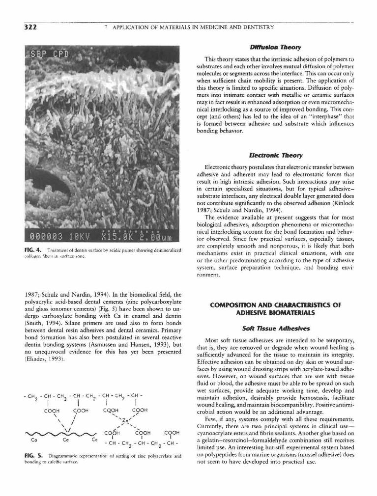
322 7 APPLICATION OF MATERIALS IN MEDICINE AND DENTISTRY
FIG. 4. Treatment of dentin surface by acidic primer showing demineralizedcollagen fibers in surface zone,
1987; Schulz and Nardin, 1994). In the biomedical field, thepolyacrylic acid-based dental cements (zinc polycarboxylateand glass ionomer cements) (Fig. 5) have been shown to un-dergo carboxylate bonding with Ca in enamel and dentin(Smith, 1994). Silane primers are used also to form bondsbetween dental resin adhesives and dental ceramics. Primarybond formation has also been postulated in several reactivedentin bonding systems (Asmussen and Hansen, 1993), butno unequivocal evidence for this has yet been presented(Eliades, 1993).
FIG* 5. Diagrammatic representation of setting of zinc polyacrylate andbonding to calcific surface.
Diffusion Theory
This theory states that the intrinsic adhesion of polymers tosubstrates and each other involves mutual diffusion of polymermolecules or segments across the interface. This can occur onlywhen sufficient chain mobility is present. The application ofthis theory is limited to specific situations. Diffusion of poly-mers into intimate contact with metallic or ceramic surfacesmay in fact result in enhanced adsorption or even micromecha-nical interlocking as a source of improved bonding. This con-cept (and others) has led to the idea of an "interphase" thatis formed between adhesive and substrate which influencesbonding behavior.
Electronic Theory
Electronic theory postulates that electronic transfer betweenadhesive and adherent may lead to electrostatic forces thatresult in high intrinsic adhesion. Such interactions may arisein certain specialized situations, but for typical adhesive-substrate interfaces, any electrical double layer generated doesnot contribute significantly to the observed adhesion (Kinlock1987; Schulz and Nardin, 1994).
The evidence available at present suggests that for mostbiological adhesives, adsorption phenomena or micromecha-nical interlocking account for the bond formation and behav-ior observed. Since few practical surfaces, especially tissues,are completely smooth and nonporous, it is likely that bothmechanisms exist in practical clinical situations, with oneor the other predominating according to the type of adhesivesystem, surface preparation technique, and bonding envi-ronment.
COMPOSITION AND CHARACTERISTICS OFADHESIVE BIOMATERIALS
Soft Tissue Adhesives
Most soft tissue adhesives are intended to be temporary,that is, they are removed or degrade when wound healing issufficiently advanced for the tissue to maintain its integrity.Effective adhesion can be obtained on dry skin or wound sur-faces by using wound dressing strips with acrylate-based adhe-sives. However, on wound surfaces that are wet with tissuefluid or blood, the adhesive must be able to be spread on suchwet surfaces, provide adequate working time, develop andmaintain adhesion, desirably provide hemostasis, facilitatewound healing, and maintain biocompatibility. Positive antimi-crobial action would be an additional advantage.
Few, if any, systems comply with all these requirements.Currently, there are two principal systems in clinical use—cyanoacrylate esters and fibrin sealants. Another glue based ona gelatin—resorcinol—formaldehyde combination still receiveslimited use. An interesting but still experimental system basedon polypeptides from marine organisms (mussel adhesive) doesnot seem to have developed into practical use.

7.5 ADHESIVES AND SEALANTS 323
FIG. 6. Structure of methyl cyanoacrylate and methyl methacrylate.
Cyanoacrylate Esters
These esters are fluid, water-white monomers that polymer-ize rapidly by an anionic mechanism in the presence of weakbases such as water or NH2 groups. Initially, methyl cyanoacry-late (Fig. 6) was used but in the past decade isobutyl andw-butyl cyanoacrylate have been found more acceptable. Thehigher cyanoacrylates spread more rapidly on wound surfacesand polymerize more rapidly in the presence of blood. Further-more, they degrade more slowly over several weeks, in contrastto the methyl ester, which hydrolyzes rapidly, yielding formal-dehyde that results in an acute inflammatory response.
These materials achieve rapid hemostasis as well as a strongbond to tissue. However, the polymer film is somewhat brittleand can be dislodged on mobile tissue, and the materials canbe difficult to apply on large wounds. Because of adverse tissueresponse and production of tumors in laboratory animals, cya-noacrylates are not approved for routine clinical use in theUnited States although a commercial material based on n-butylcyanoacrylate (Histoacryl blue) is approved by several othercountries.
The current uses are as a surface wound dressing in dentalsurgery, especially in periodontics, and in life-threatening appli-cations such as brain arteriovenous malformations. Reports ofsarcomas in laboratory animals (Reiter, 1987) late complica-tions after dura surgery (Chilla, 1987), and evidence of in vitrocytotoxicity (Ciapetti et al., 1994) appear likely to restricttheir further use in spite of work on synthesis of new typesof cyanoacrylate,
Fibrin Sealants
Fibrin sealants involve the production of a synthetic fibrinclot as an adhesive and wound-covering agent. The conceptof using fibrin dates back to 1909 but was placed on a specificbasis by Matras et al. in 1972 (Schlag and Redl, 1987). Thecommercial materials first available (Tisseel, Tissucol, Fibrin-Kleber) consisted of two solutions that are mixed immediatelybefore application to provide a controlled fibrin deposition.More recently a "ready to use" formulation (Tisseel Duo) hasbeen introduced.
The essential components of these solutions are as follows:
Solution A Solution B
Fibrinogen Thrombin
Aprotinin CaO2
The fibrinogen is at a much higher concentration than that inhuman plasma. On mixing the two solutions, a reaction similarto that of the final stages of blood clotting occurs in thatpolymerization of the fibrinogen to fibrin monomers and awhite fibrin clot are initiated under the action of thrombinand CaCl2.
Fibrinogen for commercial material is manufactured fromthe pooled plasma of selected donors. The material is sub-jected to in-process virus inactivation and routinely screenedfor hepatitis virus and HIV (Schlag and Redl, 1987). Tominimize these risks, recent processes produce the fibrinogenin a "closed" blood bank or from the patient's own blood(Silberstein et al., 1988; Lerner and Binar, 1990). Autologousfibrin glue now appears to be the approach of choice (Taweset al., 1994).
Fibrin sealant has four main advantages: (1) it is hemostatic,(2) it adheres to connective tissue, (3) it promotes wound heal-ing, and (4) it is biodegradable, with excellent tissue tolerance(Schlag and Redl, 1987). The adhesive strength is not as highas cyanoacrylates but is adequate for many clinical situations.Possible complications include formation of antibodies andthrombin inhibitors. The material has been used in a widevariety of surgical techniques that are reviewed in a seven-volume report by Schlag and Redl (1987) and in numerouspapers in the recent literature (Lerner and Binar, 1990; Taweset al., 1994). The composition may be adjusted to promotehemostasis, for example, or to minimize persistence of the clotto avoid fibrosis. The use of fibrin sealant alone or in admixturewith bone chips, tricalcium phosphate, and antibiotics in ortho-pedic surgery has been reviewed (Schlag and Redl, 1987). Morerecently, the material has been used as a drug release vehiclefor local sites.
Gelatin-Resorcinol-Formaldehyde Glue
This glue was developed in the 1960s by Falb and co-workers (Falb and Cooper, 1966; Cooper et al., 1972) as aless toxic material than methyl cyanoacrylate. The material isfabricated by warming a 3 :1 mixture of gelatin and resorcinoland adding an 18% formaldehyde solution. Cross-linking takesplace in about 30 sec.
This glue was used in a variety of soft tissue applicationsbut technical problems and toxicity have limited its applicationin recent years to aortic dissection (Nakayama et al., 1994). Inattempts to overcome the toxicity and potential rnutagenicity/carcinogenicity of the formaldehyde component, modified for-mulations have been developed in which other aldehydes suchas glutaraldehyde and glyoxal (Ennker et al., 1994a,b) aresubstituted for the formaldehyde. Favorable results with thismaterial (GR-DIAL) have been reported (Ennker et al.,1994a,b).
Bloadhesives
Bioadhesives are involved in cell-to-cell adhesion, adhesionbetween living and nonliving parts of an organism, and adhe-sion between an organism and foreign surfaces. Adhesives pro-duced by marine organisms such as the barnacle and the musselhave been extensively investigated over the past 20 years be-

324 7 APPLICATION OF MATERIALS IN MEDICINE AND DENTISTRY
FIG. 7. Auto-polymerizing methyl methacrylate systems as used in dental resinsand acrylic bone cement. (From R. Roydhouse (1989), in Dental Materials Propertiesand Selection, W. J. O'Brien, ed., p. 129. Quintessence Books, Chicago, with per-mission.)
cause of their apparent stable adhesion to a variety of surfaces Hard tissue Adhesivesunder adverse aqueous conditions. These studies have shownthat these organisms secrete a liquid acidic protein adhesive As previously noted, prostheses can be attached to calcifiedthat is cross-linked by a simultaneously secreted enzyme sys- tissues (bone>tooth enamel, dentin) by gross mechanical inter-tem. The bonding probably involves hydrogen and ionic bond- locking to machined surfaces. Thus, room temperature-poly-ing from the acidic groups (Waite et al., 1989). merizing methyl methacrylate (Fig. 7) systems are used to fix
The adhesive from the mussel has been identified as a poly- orthopedic implants (e.g., acrylic bone cement, see Chapterphenolic protein, molecular weight about 130,000 Da, which 7.7) and for dental restorations. The former, in a closed system,is cross-linked by a catechol oxidase system in about 3 min. has been relatively successful. However, conditions are muchA limiting factor in the practical use of this material is the more stringent in the mouth because of the changing environ-difficulty of extracting it from the natural source. The basic ment, thermomechanical stresses on the bond, and the presenceunit of the polyphenolic protein has been identified as a specific of oral bacteria that result in renewed tooth decay. Thus, con-decapeptide. Recombinant DNA technology and peptide syn- siderable development of new dental cements and adhesivethesis have been used in attempts to produce an affordable systems has occurred in recent years in attempts to provide aadhesive with superior properties. Little information has been leakproof bond to attach fillings, crowns, and veneers to thereported on the performance of these materials. tooth (Fig. 8).

7.5 ADHESIVES AND SEALANTS 325
carboxyl groups form a complex to Ca ions in the surfaceof the tissue (Fig. 5). The zinc polycarboxylate cements haveadequate physical properties, excellent biocompatibility in thetooth, and proven adhesion to enamel and dentin (Smith,1988).
The glass ionomer cements are also based on polyacrylicacid or its copolymers with itaconic or maleic acids, bututilize a calcium aluminosilicate glass powder instead of zincoxide (Smith, 1988, 1994). In this case, the cements set bycross-linking of the polyacid with Ca and Al ions from theglass. The set structure and the residual glass particles yielda stronger, more rigid cement (Table 1) but with adhesive
FIG. 8. Leakage of oral fluids and bacteria around dental filling material in properties similar to the zinc polyacrylate cements. In recenttooth crown. (From R. W. Phillips (1991). Science of Dental Materials, 9th Ed., matenals the polyacid molecule contains both ionic Carboxyl-p . 6 2 , W . B . Saunders, Philadelphia, with permission.) 1 1 - 1 1 i i i - • j i
ate and polymenzable methacrylate groups and is inducedto set both by an acid-base reaction and visible light polymer-ization. These cements are widely used clinically. Adhesivebonding but not complete sealing is obtained because of
Dental cements are traditionally fast-setting pastes obtained imperfect adaptation to the bonded surfaces under practi-by mixing solid-liquid components. Most of these materials cal conditions.set by an acid-base reaction and more recent resin cements Resin cements are fluid or pastelike monomer systems basedset by polymerization (Smith, 1988, 1991). on aromatic or urethane dimethacrylates (Fig. 9). Silanated
Zinc phosphate cement is the traditional standard. This ceramic fillers may be present to yield a composite composition,material is composed primarily of zinc oxide powder and a The two-component materials polymerize on mixing through50% phosphoric acid solution containing Al and Zn. The a two-part organic peroxide—tertiary amine initiator—activatormixed material sets to a hard, rigid cement (Table 1) by forming system in about 3 min. More recent are one-component materi-an amorphous zinc phosphate binder. Although the cement is als containing diketone polymerization initiators that achievegradually soluble in oral fluids and can irritate pulp, it is clini- polymerization in about 30 sec by exposure to visible (blue)cally effective over 10—20-year periods. The bonding arises light energy. These set materials are strong, hard, rigid, insolu-entirely from penetration into mechanically produced irregu- ble, cross-linked polymers (Table 1). Bonding is achieved bylarities on the surface of the prepared tooth and the fabricated mechanical interlocking to surface roughness. In recent materi-restorative material. Some interfacial leakage occurs because als, reactive adhesive monomers may also be present (see theof cement porosity and imperfect adaptation (Fig. 1), but this following discussion), conferring also a presumed chemisorp-is usually acceptable since the film thickness is generally below tion mechanism.100 /urn. Enamel and dentin bonding systems are composite poly-
Poly carboxylic acid cements were developed in 1968 (Smith mer-ceramic formulations similar to resin cements but are1988, 1994) to provide materials with properties comparable more complex systems containing reactive monomers. Theirto phosphate cements but that would adhere to calcified tissues. use usually involves an acidic pretreatment of the tooth surface,Zinc polyacrylate (polycarboxylate) cements are formed from an unfilled monomer bonding (primer resin) composition tozinc oxide and a polyacrylic acid solution. The metal ion cross achieve good wetting of the tooth surface, and a filled bondinglinks the polymer structure via carboxyl groups, and other agent for the bulk of the bond. These materials are used to
TABLE 1 Properties of Dental Cements and Sealants
Strength (MPa)Modulus of elasticity Fracture toughness
Material Compressive Tensile (GPa) K\C MN~3/2
Zinc phosphate 80-100 5-7 13 -0.2
Zinc poiycarboxylate 55-85 8-12 5-6 0.4-0.5
Glass ionomer 70-200 6-7 7-8 0.3-0.4Resin sealant unfilled 90-100 20-25 2 0.5Resin sealant filled 150 30 5
Resin cement 100-200 30-40 4-6Composite resin filling material 350-400 45-70 15-20 1.6

326 7 APPLICATION OF MATERIALS IN MEDICINE AND DENTISTRY
FIG. 9. Structures of some dimethacrylate monomers used in dental composite filling and bondingsystems.
attach composite resin restorative materials, ceramic veneers, ing agents. The resulting resin tags (5—50 (Jim long) inand orthodontic metal and ceramic brackets to enamel and the surface of the tissue result in efficient micromechanicaldentin surfaces. Because of the different composition and physi- interlocking with a potential tensile bond strength of aboutcal properties of enamel and dentin (see Chapter 3.4), more 20 MPa, which is equivalent to cohesive failure in the resincomplex and greater demands are placed on multipurpose ad- or in the enamel.hesive systems intended for both tissues. Bonding to dentin currently involves pretreatment of the
Bonding to enamel is achieved by pretreating the surface prepared (machined) surface with acidic solutions (phosphoric,with 35—50% phosphoric acid for 30—60 sec as described nitric, maleic acids) or ethylenediaminetetracetic acid (EDTA)earlier (Fig. 3). This resulting washed and dried surface is to remove cutting debris (the smear layer). This procedurereadily wettable and penetratable by resin cements and bond- opens the orifices of the cut dentinal tubules and creates micro-

7.5 ADHESIVES AND SEALANTS 327
FIG. 10. Reactive monomer structures for bonding to calcific tissues. M-R,monomer portion of molecule. (After Asmussen, E., Aranjo, P. A., and Pentsfeld,A. 1989, Trans. Acad. Dent. Mater. 2: 59.)
porosity in the surface (Fig. 4). A primer treatment is thenapplied that comprises a reactive monomer system (Fig. 10)containing a carboxylate or a polyphosphate function, depend-ing on the type of product. These primers also contain hydro-philic monomers, such as hydroxyethyl methacrylate (HEMA),and may also contain water.
The function of the primer is to penetrate the demineral-ized dentin surface and facilitate wetting by an unfilleddimethacrylate bonding resin which is subsequently applied.Polymerization of this treatment layer by visible light activa-tion results in the formation of micromechanical bonds bypenetration into the dentin and surface tubules, forming theso-called hybrid layer (Nakabayashi et al., 1991) or resin-interdiffusion zone (Van Meerbeck et al., 1992). Chemicalinteraction with the hydroxyapatite and/or proteinaceousphases of the dentin surface may also occur (Asmussen andHansen, 1993). However, direct chemical evidence has notbeen provided yet for the postulated interactions (Eliades,1993). Under the best conditions, initial tensile bond strengthsof 15—25 MPa can be obtained depending on test conditions.The long-term durability of these bonds under oral conditionsis being investigated.
NEW RESEARCH DIRECTIONS
As a result of the experience of the past two decades, theproblems involved in developing an adhesive system for both
soft and hard tissues have been addressed. Nevertheless, it isdifficult to reconcile short- and long-term biocompatibiiityneeds with chemical adhesion mechanisms that use reactivemonomer systems.
Where relatively temporary adhesion is required, as inwound healing, systems based on natural models that allowbiodegradation of the adhesive and interface and subsequentnormal tissue remodeling appear to merit further development.For longer term durability in both soft and hard tissues, hydro-philic monomers and polymers of low toxicity which can bothdiffuse into the tissue surface and form ionic bonds across theinterface seem to be the most promising approaches. Evidencehas been obtained of the need for hydrophobic-hydrophilicbalance in adhesive monomer systems (Nakabayashi et al.,1991). The use of hydrophilic monomers such as hydroxyethylmethacrylate in commercial materials has facilitated surfacepenetration.
On calcified surfaces, the use of hydrophilic electrolytessuch as the polycarboxylates has demonstrated that provenionic bonding in vitro can also be achieved in vivo. An advan-tage of such systems is that surface molecular reorientationscan improve bonding with time. Encouraging preliminary re-sults have been obtained with such glass ionomer cementsin orthopedics and there is considerable scope for the futuredevelopment of such polyelectrolyte cements.
A practical limitation in many systems is ease of manipula-tion and application. For example, the effectiveness of thefibrin sealant is critically dependent on proper mixing of theingredients and uniform application. Further technology trans-fer could improve this often-neglected area of adhesive develop-ment. For example, the visible-light polymerization technologydeveloped in dentistry that allows extended working time andcuring "on demand" in a few seconds could usefully be appliedto medical applications. Laser activation of fibrin sealants hasreceived an initial trial.
The development of more efficient adhesives and sealantsthat, in addition to enhancing the durability of current applica-tions, would permit new applications such as osteogenic bonespace fillers, percutaneous and permucosal seals, and functionalattachment of prostheses is a challenging problem for thefuture.
Bibliography
Asmussen, E., de Aranjo, P. A., Peutzfeldt, A. (1989). In vitro bondingof resins to enamel and dentin: an update. Trans. Acad. Dent.Mater. 2: 36-63.
Asmussen, E. and Hansen, E. K. (1993). Dentine bonding systems, inState of the Art on Direct Posterior Filling Materials and DentineBonding, G. Vanherle, M. Degrange, G. Willems, eds. Cavex Hoi-land BV, Haarlem, pp. 33-47.
Charnley, J. (1970). Acrylic Cement in Orthopaedic Surgery. E. S.Livingstone, Edinburgh.
Chilla, R. (1987). Histoacryl-induzierte Spatkomplikationen nach Dur-aplastiken an der Pronto- und Otobasis. HNO 35: 250—251.
Chopin, D. K., Abbou, C., Lottiman, H. B., Topoz, P., Popov, Z.,Lang, T. R., Buisson, C. L., Belghiti, D., Colombel, M., and Auvert,J. M. (1989). Conservative treatment of renal allograft rupturewith polyglactin 910 mesh and gelatin resorcinol formaldehydeglue. /. Urol. 142: 363-365.

328 " APPLICATION OF MATERIALS IN MEDICINE AND DENTISTRY
Ciapetti, G., Stea, S., Cenni, E., Sudanese, A., Marraro, D., Toni, A., sion. in Handbook of Adhesive Technology, A. Pizzi and K. L,and Pizzoferrato, A. (1984). Toxicity of cyanoacrylates in vitro Mittal, eds., Marcel Dekker, New York, pp. 19-33.using extract dilution assay on cell cultures. Biotnater. 15: 92-96. Silberstein, L. E., Williams, L. J., Hughlett, M. A., Magee, D. A., and
Cooper, C. W., Grode, G. A., and Falb, R. D. (1972). The chemistry Weisman, R. A. (1988). An autologous fibrinogen-based adhesiveof bonding-alternative approaches to the joining of tissues, in Tissue for use in otologic surgery. Transfusion 28: 319-321.Adhesives in Surgery, 1. Matsumoto, ed., Medical Examination Skeist, I. (1990). Handbook of Adhesives, 3rd ed. Van Nostrand Rein-Publ., New York, pp. 189-210. hold, New York.
Coover, H. W., Jr., and Mclntire, J. M. (1972). The chemistry of Smith, D. C. (1971). Medical and dental appiicarions of cements. /.cyanoacrylate adhesives. in Tissue Adhesives in Surgery, T. Matsu- Biomed. Mater. Res. Symp. 1: 189—205.inoto, ed., Medical Examination Publ., New York, pp. 154-188. Smith, D. C. (1988). Dental cements. Adv. Dent. Res. 2(1): 134-141.
Eliades, G. C. (1993). Dentin bonding systems, in State of the Art Smith, D. C. (1991). Dental cements. Curr. Opin. Dent. 1: 228-234.on Direct Posterior Filling Materials and Dentine Bonding, G. Smith, D. C. (1994). Development of glass ionomer cement systems, inVanherle, M. Degrange, and G. Willems, eds. Cavex Holland BV, Glass lonomers: The Next Generation, P. Hunt, ed., InternationalHaarlem, pp. 49—74. Symposia in Dentology, Philadelphia, pp. 1—12.
Ennker, J., Ennker, L C., Schoon, D., Schoon, H. A., Dorge, S., Messier, Tawes, R. L., Jr., Sydorak, G. R., and DuVall, T. B. (1994). AutologousM., Rirnpler, M., and Hetzer, R. (1994a). The impact of gelatin- fibrin glue: the last step in operative haemostasis. Am. J. Surg.resorcinol-formaldehyde glue on aortic tissue: a histomorphologic 168: 120-122.examination. /. Vascular Surg. 20: 34—43. Vanherle, G., Degrange, M., and Willems, G. (eds.) (1993). State of
Ennker, I, C., Ennker, J., Schoon, D., Schoon, H. A., Rimpler, M., the Art on Direct Posterior Filling Materials and Dentine Bonding.and Hetzer, R. (1994b). Formaldehyde free collagen glue in experi- Cavex Holland BV, Haarlem.mental lung gluing. Ann. Thoracic Surg. 57: 1622-1627. Van Meerbeck, B., Inokoshi, S., Braem, M., Lambrechts, P., and Van-
Falb, R. D., and Cooper, C. W. (1966). Adhesives in surgery. New herle, G. (1992). Morphological aspects of resin-dentin interdiffu-Scientist 308—309. sion zone with different dentin adhesive systems. J. Dent. Res.
Gluck, T. (1891). Referat uber die durch das moderne chirugische 71: 1530-1540.Experiment gewonnen positiven Resultate, betrifind die Naht Waite, J. H. (1989). The glue protein of ribbed mussels (Genkenskaund den Ersatz von defecten hoherer Gewebe sowie uber die denissa): a natural adhesive with some features of collagen. /.Verwerthung resorbirbarer und lebendiger Tampons in der Comp. Physiol. [B] 159(5): 517-525.Chirurgie. Langenbecks Archiv fur Klinische Chirugie 41:187-239.
Haring, R. (1972). Current status of tissue adhesives in Germany, inTissue Adhesives in Surgery, T. Matsumoto, ed., Medical Examina-
tion Publ., New York, pp. 430. . 7.6 OPHTHALMOLOGIC APPLICATIONSJohnson, G., Powell, V., and Gordon, G. (1991). Dentin bonding
agents: a review. /. Am. Dent. Assn. 122: 34-41. MtSuel R Re'o?°Kinlock, A. J. (1987). Adhesion and Adhesives. Chapman and Hall,
London. Light that penetrates into the eye is partially refracted inLee, C. H., and Grauer, G. M. (1989). Oligomers with pendant isocya- the cornea, passes through the aqueous humor and the pupil
nate groups as adhesives for dentin and other tissues. /. Dent. Res. (the opening in the center of the iris), is further refracted in68: 484-488. the crystalline lens, passes through the vitreous humor, and
Lee, L-H. (ed.) (1991a). Fundamentals of Adhesion. Plenum Publ., converges on the retina (Fig. 1), Diverse polymeric devices,New York. sucj.j as Spectacles, contact lenses, and intraocular implants,
Lee, L-H. (1991b). Adhesive Bonding. Plenum Publ., New York. ^ ̂ tQ correcf Ac dcal functiofi of ̂ £ye The ̂ ^Lerner, R., and Binar, N. S. (1990). Current status of surgical adhesives. i • i t - j L c. \ • L
' * ,„ \,r 1 0 < used in spectacle lenses are outside the scope or this chapter./. Surg. Res. 48: 165-181. „ f , . . . . . • i i
,, -r / io-7->\ -r A a • • c \* j ic • Contact lenses, however, being in intimate contact with theMatsumoto, I . (1972). Tissue Adhestves in Surgery. Medical Examina- . ' , - i .tion Publ New York tissues or the eye, are subject to the same regulations that
Nakabayashi,' N., Nakamura, M., and Yasuda, N. (1991). Hybrid g°vern the use of implant materials, and they are included inlayer as a dentin bonding mechanism./. Esthet. Dent. 3:133-135. this chapter with other biomaterials used to preserve and to
Nakayama, Y., Kitamura, S., Kawachi, K., Inoue, K., Tomiguchi, S., restore vision, such as intraocular implants.Fukutomi, M., Kobayashi, S., Kawata, T., and Yoshida, T. (1994).Efficacy of GRF glue on surgery for Type A aortic dissection. /.Jpn. Assn. Thoracic Surg. 42: 1021-1026. CONTACT LENSES
Neuse, E. W., and Mizrahi, E. (1994). Bonding materials and tech-niques in dentistry, in Handbook of Adhesive Technology. A. Pizziand K. L. Mittal, eds., pp. 629-656, Marcel Dekker, New York. General Properties
Phillips, R. W., and Ryge, G. (eds.) (1961). Adhesive Restorative Dental „ , . , , . , , ,,; . , ' . , T . r r T 1 1 n c n ui TJ i u c Contact lenses are optical devices that must have good trans-Matenals, National Institutes of Health, U.S. Public Health Ser- . . , . .. . ,. . r_ . . . .,**•,vi - Wishi t mission or visible light. Pigments and dyes are added to some
PizzI^A., and Mittal, K. L. (eds.) (1994). Handbook of Adhesive contact lenses for cosmetic effect. Contact lenses also may haveTechnology. Marcel Dekker, New York. ultraviolet (UV) light-absorbing additives, usually copolymer-
Schlag, G., and Red!, H. (1987). Fibrin Sealant in Operative Medicine, ized in the contact lens material, to protect the eye from theVol. 4, Plastic Surgery—Maxillofacial and Dental Surgery, harmful effects of UV light. UV light absorbed by the normalSpringer-Verlag, Berlin. crystalline lens is harmful to the retina and also may contribute
Schulz, J., and Nardin, M. (1994). Theories and Mechanisms of Adhe- to the clouding of the lens (cataract) (Miller, 1987).

7.6 OPHTHALMOLOGIC APPLICATIONS 329
FIG. I. Schematic representation of the eye.
The principal properties sought in contact lens materials, Soft Hydrogel Contact Lensesin addition to the required optical properties, chemical stability,and amenability to manufacture at reasonable cost, are high The soft hydrogel contact lenses (SCL) are supple and fitoxygen transmissibility (to meet the metabolic requirements ***& on the corneal surface. Because there is little tear ex-of the cornea), tear film wettability (for comfort), and resistance change under these lenses, most of the oxygen that reaches theto accumulation on the lens surfaces of mucus/protein/lipid cornea must permeate through the lens. The oxygen permeabil-deposits from the tear film and other external sources. Contact ^ coefficient of hydrogel materials increases exponentiallylenses also must be easy to clean and disinfect (Kastl, 1995). with the water content.
Most of the available contact lenses were developed with The hydrogel lenses are made of slightly cross-linked hy-the important property of oxygen permeability in mind. The drophilic polymers and copoiymers. The original hydrogel con-oxygen permeability coefficient, P, is a property characteristic tact lens material was poly(2-hydroxyethyl methacrylate)of a material. [P = Dk, where D is the diffusivity, in cm2/sec, (PHEMA) (Wichterle and Lim, 1960); at equilibrium swellingand k is the Henry's law solubility coefficient, in cm3 (STP)/ in physiological saline solution, it contains about 40% water ofcm3 mm Hg.] For a given contact lens, its oxygen transmissibil- hydration. (Hydration of hydrogel contact lenses is customarilyity (Dk/L) is more important than its permeability; oxygen given as a percentage of water by weight, on a wet basis.) Thetransmissibility is defined as the oxygen permeability coefficient oxygen transmissibility of the original rather thick PHEMAof the material divided by the average thickness of the lens (L, hydrogel contact lenses was found to be insufficient for normalin cm) (Holden et al., 1990). corneal metabolism. New hydrogel contact lenses were soon
For oxygen permeability, the ideal contact lens would be developed with higher water content or with a water contentmade of poly (dimethyl siloxane). For better mechanical proper- similar to that of PHEMA but more amenable to fabricationties and manufacture, most silicone elastomeric lenses have in an ultrathin modality. New fabrication techniques were alsobeen made of diverse poly(methyl phenyl vinyl siloxanes). Be- developed to make ultrathin PHEMA lenses. This takes advan-cause of its hydrophobic character, to be useful, a silicone tage of the law of diffusion which, applied to contact lenses,rubber lens must be treated in an RF-plasma reactor or other will guarantee that for any lens type under the same conditionssuitable procedure to make its surface hydrophilic and tolerated of wear, the oxygen flux through the lens will double whenon the eye. Nevertheless, the silicone rubber lenses have not the thickness is halved.been very successful for general cosmetic use, not only because Other hydrogel contact lens materials include HEMA copol-of surface problems and comfort, but principally because they ymers with other monomers such as methacrylic acid, acetonehave a strong tendency to adhere to the cornea. acrylamide, and vinyl pyrrolidone. Commonly used also are
There are currently a wide variety of contact lens materials copoiymers of vinyl pyrrolidone and methyl methacrylate, andwith diverse physical properties that determine the fitting char- of glyceryl methacrylate and methyl methacrylate. A varietyacteristics of the lens on the eye (Kastl, 1995). of other monomers as well as a variety of cross-linking agents

330 7 APPLICATION OF MATERIALS IN MEDICINE AND DENTISTRY
TABLE 1 Chemical Composition of Some Hydrogel high oxygen permeability) with vinyl pyrrolidone (whichContact Lenses imparts wettability) and methyl methacrylate (which imparts
•— ' rigidity). This flexible, nonhydrated contact lens, made byPolymer USANa % H2O the molding procedure, had a high oxygen permeability and,
—————— owing to its high fluorine content, was claimed to be more2-hydroxyethyl methacrylate (HEMA) resistant to coating by tear proteins than other contact
with ethyleneglyco! dimethacrylate lens materiais> At this time, the FFP lenses are no longer
^EGDM) Pol^macon 38 commercially available.HEMA with methacrylic acid (MAA) and Ocufilcon A 44
EGDM Ocufilcon C 55
HEMA with sodium methacrylate and 2-ethyl-2-(hydroxymethyl)-l,3- IM~I*I r -+ tpropanedio! trimethacrylate Etafilcon A 58 *>&** *-ont*<* LeiiSCS
HEMA with divinyl benzene, methyl The rigid contact lenses, as well as the FFP lenses, fit looselymethacrylate (MMA) and l-vinyl-2- on tne cornea and move with the blink more or less freely overpyrrolidone (VP) Tetrafilcon A 43 the tear film that separates tne lens from the corneal surface.
HEMA with VP and MAA Perfilcon A 71 The mechanical properties of rigid and FFP contact lenses mustHEMA with N-(l,l-dimethyl~3-oxobutyl) be such that any flex on the lens provoked by the blink must
acrylamide and 2-ethyl-2- recover instantaneously at the end of the blink.(hydroxymethyl)-l,3-propanediol Bufilcon A 45 The first widely available contact lenses were made of poly-trimethacrylate Bufilcon B 55 (methyl methacrylate), which is an excellent optical biomaterial
2,3~Dihydroxypropyl methacrylate with in almost all respects except for its virtual impermeability toMMA Crofilcon A 39 oxygen. Several materials that were specially developed for the
VP with MMA, allyl methacrylate and Lidofilcon A 70 manufacture of rigid gas-permeable (RGP) contact lenses areEGDM Lidofilcon B 79 copolymers of methyl methacrylate with siloxanylalkyl meth-
MAA with HEMA, VP and EGDM Vifilcon A 55 acrylates (Refojo and Dabezies, 1984). To compensate for thehydrophobic character imparted to the polymer by the high
"U.S. adopted name. siloxane content of these copolymers (required for oxygen per-meability), the copolymer also contains some hydrophilic corn-
are used as minor ingredients in hydrogel contact lenses onomers. The most commonly used hydrophilic comonomer in(Refoio 1979) (Table 1) rigid lenses is methacryhc acid. There are also minor ingredients
Hydrogel lenses have been classified by the U.S. Food and and cross-linking agents. A diversity of RGP contact lenses,Drug Administration (FDA) into four general groups: low wa- consisting of different but closely related comonomers used inter (<50% H,0), nonionic; high water (>50% H2O), non- a variety of proportions to obtain the most desirable properties,ionic; low water, ionic; and high water, ionic. The ionic charac- are commercially available (Table 2). However, any subtleter is usually due to the presence of methacrylic acid, which change m the chemistry of a contact lens material mightis responsible for higher surface protein binding to the contact stton^ affect lts dimcal Performance. As a general rule, thelenses. High water of hydration is a desirable property for oxygen permeability coefficient of the siloxanylalkyl methacry-good oxygen permeability, but it carries some disadvantages, late contact lens materials is inversely proportional to thesuch as friability and protein penetration into the polymer density.network. Physiologically and optically, ultrathin low-water- The development of the fluorine-containing contact lensescontent contact lenses can perform very well as daily-wear and the realization that the fluoroderivatives may improveienses oxygen permeability and resistance to deposit formation caused
As a result of temperature changes and water evaporation, contact lens chemists to include a fluoroalkyl methacrylate orall hydrogel contact lenses dehydrate to some degree on the a similar fluorine-content monomer as an additional ingredienteye. Higher-water-content lenses dehydrate more than low- m the siloxanylalkyl methacrylate-comethyl methacrylate RGPwater-content lenses, and thin lenses dehydrate more easily contact lens materials. These perfluoroalkyl-siloxanylalkyi-than thick lenses (Refojo, 1991). A drawback of high-water- methyl methacrylate contact lenses have high oxygen perme-content, thin hydrogel contact lenses is that as they dehydrate ablllty and' supposedly, better surface properties than the non-on the eye, they induce corneal epithelium injuries by a mecha- fluorine-containing rigid contact lenses,nism still unclear. Therefore, the ideal hydrogel contact lens Cellulose acetate butyrate (CAB) is also used as a rigidwould be ultrathin, resistant to mechanical damage, made of oxygen-permeable contact lens material. However, CABa nonionic polymer, and retain a high water content (i.e., not only has relatlvely low oxyge" permeability compared>70% H,O) on the eve w't'1 siloxanylalkyl methacrylate copolymers but also has
low scratch resistance and tends to warp with humidity
Flexible Fluoropolymer Lenses changes.Other copolymers useful as contact lens materials are iso-
The flexible fluoropolymer (FFP) lens was made from a butyl and isopropyl styrene, with hydrophilic comonomers ofcopolymer of a telechelic perfluoropolyether (which imparts the HEMA or vinyl pyrrolidone type.

7.6 OPHTHALMOLOGIC APPLICATIONS 331
TABLE 2 Composition of Some Rigid Gas-Permeable corneal surface and is reepithelialized with the recipient cornealContact Lenses epithelium (Werblin et al., 1987). A modification of this tech-
—— nique attempts to obtain similar results with an artificial mate-Polymer USANa rial that would heal into the donor cornea and be able to grow
the epithelium of the donor cornea on its surface (Fig. 2).Cellulose acetate dibutyrate Porofocon An epithelium that has become irregular through swelling
Cabufocon and proliferation has been replaced by an artificial epithelium3~[3,3,5,5,5-pentamethyl-l,l- made of a hard plastic contact lens glued with a cyanoacrylate
bis[pentamethyldisiloxanyl)oxy] adhesive to the corneal stroma (Fig. 2). This procedure hastrisiloxanyl]propyl methacrylate, with methyl not been successful mainly because of failure of the glue tomethacrylate (MMA), methacrylic acid maintain a tight attachment of the prosthesis to the corneal(MAA) and tetraethyleneglycol stroma and also because of epithelial penetration between thedimethacrylate (TEGDMA) Silafocon prosthesis and the cornea.
MMA with MAA, EGDMA, 3-[3,3,3,-trimethyl~l,l-bis(trimethylsiloxy)disiloxanyl] Artificial CorneASpropyl methacrylate (TRIS) and N-(l,l-dimethyl-3-oxybutyl)acrylarnide. Nefocon Corneal transplants from donor eyes are usually highly suc-
VP with HEMA, TRIS, allyl methacrylate and cessfuL In the rare instance of transput failure, an opaquea-methacryloyl^-(methacryloxy) Cornea can be rePlaced with an artifidal cornea (k^topros-Poly(oxyethyiene-co-oxy(dimethylsilylene)- thesis) (Barb,er> 1988>' These are usually through-and-throughco-oxyethyiene, Mesifilcon corneal implants, consisting of a central optical portion and
some modality of skirt that fixes the prosthesis to the recipientTRIS ™*hj '̂ dimethyl ltaconate> MAA cornea (Fig. 3). The main problem with through-and-through
and I EGDMA. Itafocon keratoprostheses is common to all kinds of implants that areTRIS with 2,2,2,-trifluoro-l-(trifluoromethyl) not fully buried in the recipient tissue: faulty tissue-prosthesis
ethyl methacrylate, l-vinyl-2-pyrrolidone interface, epithelium downgrowth, and tissue ulceration and(VP), MAA and ethyleneglycol infection around the prosthesis. The most feasible solution todimethacrylate (EGDMA). Melafocon these problems would be the development of a material for
TRIS with 2,2,2-trifluoroethyl methacrylate, tne optical portion of the keratoprosthesis that would acceptMAA, MMA, VP with EGDMA. Paflufocon growth and attachment of transparent epithelium on its sur-
. _^___ . face- Also needed are biomaterials that would heal into theaU.S. adopted name. recipient corneal tissue.
CORNEAL IMPLANTS
The cornea is an avascular tissue that consists of threeprincipal layers (Fig. 1). The outermost layer, which itself con-sists of about five cellular layers, is the epithelium. The centraland main portion of the cornea is the stroma, a collagenousconnective tissue that is 78% hydrated in its normal state.Normal corneal hydration is disrupted by injury to the limitingepithelial and endothelial membranes. The endothelium is theinnermost monocellular layer, which by means of a "pump-leak" mechanism, is mostly responsible for maintaining normalcorneal hydration. Swelling, tissue proliferation, and vasculari-zation may compromise the transparency of the cornea. Thereare several types of corneal implants (Refojo, 1986a; Abel,1988) that replace all or part of the cornea.
LplkeratophaklA and Artificial EpitheliumFIG. 2. Schematic representation of superficial corneal implants. (Top) In
To correct the optics of the eye after cataract extraction, the epikeratophakia procedure, the corneal epithelium is removed before the
the surgeon may perform an epikeratophakia procedure which ™plant f_p'aced °ntl?e str°T' surface.fnd epitheil"m grows over *f impl,ant:. , I • i - f t rr-i (Bottom) I he artificial epithelium or epikeratoprosthesis is a contact lens glued
consists Of transplanting a slice of donor cornea. The trans- to a deepithelialized cornea. Ideally, the epithelium should not grow over orplanted tissue heals into a groove carved into the recipient under the glued-on lens.

332 7 APPLICATION OF MATERIALS IN MEDICINE AND DENTISTRY
Artificial Endothelium
The corneal endothelium has been replaced, but not verysuccessfully in the long term, by a silicone rubber membranethat passively controls corneal hydration (Fig. 3). Unfortu-nately, the membrane serves as a barrier not only to water butalso to the nutrients that the cornea normally receives fromthe aqueous humor.
Intrncomeal Implants
Ophthalmic surgeons may use diverse polymeric devicesto correct the optical function of the eye. Thus, intracornealimplants can be used instead of spectacles or contact lenses tocorrect nearsightedness and farsightedness (Fig. 4). The intra-corneal implants most likely to succeed are made of hydrogelmaterials tailored to have high permeability to metabolites andable to correct severe myopia (McCarey et al., 1989). Thestromal cells (keratocytes) and the epithelium receive their nu-trients from the aqueous humor and also release waste productsin the same direction. Therefore, some previously used intra-stromal implants, such as poly(methyl methacrylate) and poly-sulfone, which are impermeable to metabolites, will result inthe ulceration and vascularization of the overlying stroma.A more recent development is the intrastromal ring made ofpoly(methyl methacrylate) or silicone rubber, which maychange the corneal curvature and, hence, the eye's opticalpower. These rings can make the corneal curvature steeper,increasing the refractive power, or flatter, decreasing the refrac-tive power.
IMPLANTS FOR GLAUCOMA
Polymeric devices are used to control abnormally high in-traocular pressure in otherwise intractable glaucoma (Krupin
FIG. 3. (Top) Schematic representation of a through-and-through artificialcornea (kerastoprosthesis) that consists of an optical cylinder that penetrates theopaque tissue. The prosthesis has an intrastromal rim that holds the prosthesisin the cornea. (Bottom) Schematic representation of the artificial corneal endothe-lium that consists of a transparent membrane sutured to the posterior part ofthe cornea denuded of its endothelium. This membrane acts as a barrier to theinflow of aqueous fluid into the corneal stroma.
FIG. 4. Schematic representation of intracorneal implants used to changethe curvature of the cornea in refractive keratoplasty. (Top) An intrastromalhydrogel intracorneal implant. (Bottom) An intrastromal corneal ring.
et al., 1988). These devices consist essentially of tiny tubes thattransport the aqueous humor—which normally maintains thephysiological intraocular pressure and flows in and out of theeye in a well-regulated manner—from the anterior chamberto some artificially created space between the sclera and theother tissues that surround the eyeball; then the aqueous humoris absorbed into the blood circulation. The main problem withglaucoma implants is tissue proliferation around the outlet ofthe plastic device. Tissue proliferation, or capsule formation,takes place in and around all implanted biomateriais and mayretard or even stop the outflow of aqueous humor from the eye.
INTRAOCULAR LENS IMPLANTS
Intraocular lenses (lOLs) are used after cataract extractionto replace the opaque crystalline lens of the eye (Apple et al.,1984). lOLs consist of an optical portion and haprics thatsupport the optical portion in its proper place in the eye (Fig.5). lOLs may be placed in the anterior chamber, in the pupil,and in the posterior chamber. The last type are most commonlyused at this time; they are usually placed within the posteriorcapsule of the crystalline lens, which remains in the eye afterthe lens contents have been removed surgically (Fig. 5). A largevariety of IOL designs and shapes are available; the choice doesnot necessarily depend on need but rather on the preferences ofsurgeons and manufacturers.

7.6 OPHTHALMOLOGIC APPLICATIONS 333
The requirements of IOL materials are good optical proper- during introduction of the implant and for preserving the cor-ties and biocompatibility with the surrounding tissues. Al- neal endothelium (Fernandez-Vigoetal., 1989). Other impor-though oxygen or metabolite permeability is irrelevant for tant developments may be the surface modification of lOLslOLs, one may have to be concerned with the potential absorp- with permanent hydrophilic or hydrophobic coatings,tion in the IOL material of aqueous humor proteins or a topicalor systemic drug given to a patient wearing an IOL, particularlyif the IOL matertal is a hydrogel or silicone rubber. IMPLANTS FOR RETINAL DETACHMENT SURGERY
Most JOLs are made of poly(methyl methacrylate), and thehaptics are often made of the same material or polypropylene , • i i i /• • /• • • • i i •/-, , A i t tnoA\ r-t • r i n r v L L i TW u u A retina detached from its source of nutrition in the choroi-fiber (Applet aL, 1984 .Filtration of UV light by UV-absorb- . . . . . , . . .. , _, , ., .
. , j • * T^T • i / i dal circulation ceases to be sensitive to light. Ihe choroid ising moieties polymerized into the IOL is desirable to protect . . . . . , .°, , ._. ..i • / \* 'n -mo-7\ the vascular layer between the retina and the sclera (rig. 1).the retina (Miller, 1987). T , .7 . , , , f ,
. , , , . . , , . ,. In cases of retinal detachment, the surgeon must reattach theCorneal astigmatism may result trom tissue distortions oc- . . . _, . ' , , , , . . .
; , , ,. c i i retina to restore vision. Retinal detachment could result tromcurnng a s a consequence of t h e uneven healing or t h e wound . . . . . . , ,, , i T~7 , j -n. • i traction of a retracting vitreous humor or from seepage ofmade when the IOL was implanted. There is currently a strong ,. ., , . , °, . ,, . . , - ,
. j , c I>\T t _ - L L. • j • u liquefied vitreous through a retinal hole between the retina andinterest in developing soft lOLs, which can be inserted in the .n . . . _ . ° , . . ,, , ,. . . . . . , • j £ the choroid. Retina surgeons can often restore vision to these
eye through smaller surgical incisions that are required tor . . . , 1 1 1 1 1 1 - • i. , j i A 11 • • • i • i eves with vitreous implants and scleral buckling materialsimplanting rigid lenses. A smaller incision may result in a lower ' . QO/-L\ /p- f[\incidence of astigmatism. Soft lOLs have been made of HEMA ^ ' ' M g- J -or other hydrogels, which can be inserted into the eye fullyhydrated or in the dehydrated state; in the latter case they will VWreoifS Implantsswell in situ to their equilibrium hydration (Barrett e£al., 1986).Flexible lOLs are made also of silicone rubber and of alkyl Vitreous implants are desirable in certain difficult cases ofacrylate copolymers. retinal detachment surgery (Refojo, 1986b). Physiological sa-
Biopolymers in the form of a viscoelastic solution are also line solution, air and other gases, as well as a sodium hyaluro-used in IOL implantation. The corneal endothelium is an ex- nate solution frequently are injected into the vitreous cavitytremely delicate cell layer and can be irreversibly damaged during virtreoretinal surgery. These fluids may perform wellupon contact with an IOL, during or after insertion. The sur- as a short-term vitreous substitute. For long-term vitreous re-geon must be extremely careful not to touch the corneal endo- placement, however, the only substance used at this time, andthelium with the IOL or with any instrument used during with variable results, is silicone oil of high viscosity (1,000 tosurgery. Highly viscous, and preferably viscoelastic, solutions 12,500 centistokes) and for short-term vitreous replacement,of biopolymers such as sodium hyaluronate, chondroitin sul- perfluorocarbon compounds of low viscosity. The main prob-fate, or hydroxypropyl methylcelluose are useful adjuncts in lem with long-lasting intravitreous implants is tolerance. Reti-IOL implant surgery for maintaining anterior chamber depth nal toxicity, oil emulsification, glaucoma, and corneal clouding
are some of the complications of permanent vitreous implants.These complications may be avoided by removing the implantafter choroidal-retinal adhesion has been achieved, but implantremoval involves further surgery, is difficult to achieve com-pletely, and carries the risk of recurrence of the retinal de-tachment.
Scleral Budding Materials
Scleral buckling materials for retinal detachment surgerymust be soft and elastic. Solid silicone rubber and siliconesponge have been used successfully. More recently an acrylichydrogel made of a copolymer of 2-hydroxyethyi acrylate withmethyl acrylate has become available. It may improve the al-ready relatively small rate of infection resulting from the useof the sponge and the potential for long-term pressure necrosisof the more rigid solid silicone rubber implants (Refojo,1986b).
SURGICAL ADHESIVESFIG. 5. (Top) Schematic representation of a typical intraocular lens implantwith a central optical portion and the haptics or side-arms that hold the lens inthe eye. (Bottom) A schematic representation of the anterior segment of the eye As in most applications of polymers 3S biomedical implants,with an intraocular lens placed into the empty crystalline lens bag. in ophthalmology any polymeric device must be as free 3S

334 7 APPLICATION OF MATERIALS IN MEDICINE AND DENTISTRY
FIG. 6. Schematic representation of an eye with a detached retina. The retina can be pushed backinto its normal place by injecting a fluid in the vitreous cavity (inside arrow) while the subretinal fluidis drained (outside arrow). A scleral buckling implant (the drawing represents an encircling implant) isplaced over retinal tears to counteract the traction on the retina of a shrinking vitreous and to reapproxi-mate the retina to the underlying tissues.
possible of residual monomer. However, in the unique case of project: An interlaboratory comparison of Dk/L measurements,the cyanoacrylate surgical adhesives, the monomers are applied Optom. Vis. Sci. 67: 476-481.directly to the tissues and almost instantaneously polymerize Kaf >.P' R- <«»•>• ^95) Contact Lenses: The CLAO Guide to Basic
, ,. , , . „, , „ Science and Clinical Practice. Kendall/Hunt Publishing Co.,and adhere tenaciously to the tissues. The cyanoacrylate adhe- D b au IAsives have been used in many diverse applications in the eye Kmpin? T ? Ritch? R Camras, C. B., Bmcker, A. J., Muldoon, T. O.,but have been particularly useful in corneal perforation and Serle, J., Podos, S. M., and Sinclair, S. H. (1988). A long Krupin-ulcers as well as in gluing artificial epithelium to the corneal Denver valve implant attached to a 180° scleral explant for glau-surface and repairing retinal detachments (Refojo etal., 1971). coma surgery Ophthalmology 95: 1174-1180.
McCarey, B. E., McDonald, M. B., van Rij, G., Salmeron, B., Pettit,D. K., and Knight, P. M. (1989). Refractive results of hyperopic
Bibliography hydrogel intracorneal lenses in primate eyes. Arch, Ophthalmol.107: 724-730.
Abel, R., Jr. (1988). Development of an artificial cornea: I. History Miller, D. (ed.). (1987). Clinical Light Damage to the Eye. Springerand materials, in The Cornea: Transactions of the World Congress Verlag, New York.on the Cornea HI, H. D, Cavanagh, ed. Raven Press, New York, Refojo, M. F. (1979). Contact lenses, in Kirk-Othmer: Encyclopedia ofpp. 225-230. Chemical Technology. 3rd ed. Wiley, New York, vol. 6, 720-742.
Apple, D. J., Loftield, K., Mamalis, N., Normal, D. K.-V., Brady, Refojo, M. F. (1986a). Current status of biomaterials in ophthalmol-S. E., and Olson, R. J. (1984). Biocompatibility of implant materi- ogy. in Biological and Biomechanical Performance of Biomaterials,als: A review and scanning electron microscopic study. Am. Intrao- P. Christel, A.Meunier, and A. J. C. Lee, eds. ESsevier, Amsterdam,cular Implant Soc. J. 10: 53-66. pp. 159-170.
Barber,}. C. (1988). Keratoprostheses: past and present. Int. Ophthal- Refojo, M. F. (1986b). Biomedical materials to repair retinal detach-mol. Clin. 28: 103-109. ments. in Biomedical Materials, J. M. Williams, M. F. Nichols,
Barrett, G. D., Constable, I. J., and Stewart, A. D. (1986). Clinical and W. Zingg, eds. Materials Research Society Symposia Proc.,results of hydrogel lens implantation. /. Cataract Refract. Surg. Materials Research Society, Pittsburgh, Vol. 55, pp. 55—61.12: 623—631. Refojo, M. F. (1991). Tear evaporation considerations and contact
Fernandez-Vigo, J., Refojo, M. F., and Jumblatt, M. (1989). Elimina- lens wear, in Considerations in Contact Lens Use under Adversetion of hydroxypropyl methylcellulose from the anterior chamber Conditions, P. E. Flattau, ed., pp. 38—43. National Academy Press,of the rabbit. /. Cataract Refract. Surg. 15: 191-195. Washington, DC.
Holden, B. A., Newton-Homes, J., Winterton, L., Fatt, I., Hamano, Refojo, M. F., and Dabezies, O. H., Jr. (1984). Classification of theH., La Hood, D., Brennan, N. A., and Efron, N. (1990). The Dk types of material used for construction of contact lenses, in Contact

356 7 APPLICATION OF MATERIALS IN MEDICINE AND DENTISTRY
Agents, A. C. Tanquary and R. E. Lacey, eds. Plenum Publ., New on-off switching polymers for drug permeation and release. /. Con-York, pp. 15-71. trolled Release 11: 255-265.
Brunetti, P.,Benedetti, M. M., Calabrese, G., and Reboldi, G. P. (1991). Petersen, R. V., Anderson, R. G., Fang, S. M., Gregonis, D. E., Kim,Closed loop delivery systems for insulin. Int. }. of Artif. Organs S. W., Feijen, J., Anderson,]. M., and Mitra, S. (1980). Controlled14: 216-226. release of progestins from poly(a-amino acid) carriers, in Cow-
Heller, J. (1980). Controlled release of biologically active compounds trolled Release of Bioactive Materials, R. W. Baker, ed. Academicfrom bioerodible polymers, Biomaterials 1: 51—57. Press, New York, pp. 45—60.
Heller,]. (1984). Biodegradable polymers in controlled drug delivery. Pitt, C. G., Marks, T. A., and Schindler, A. (1980). BiodegradableCRC Crit. Rev. in Tberap. Drug Carrier Syst. 1: 39-90. delivery systems based on aliphatic polyesters: applications to con-
Heller, J. (1985). Controlled drug release from poly(ortho esters): a traceptives and narcotic antagonists, in Controlled Release of Bio-surface eroding polymer. /. Controlled Release 2: 167-177. active Materials, R. W. Baker, ed. Academic Press, New York,
Heller, J. (1987). Bioerodible hydrogels. in Medicine and Pharmacy, pp. 19-43.N. A. Peppas, ed. CRC Press, Boca Raton, FL, Vol. Ill, pp. Rosen, H. B., Chang, ]., Wnek, G. E., Linhardt, R. ]., and Langer, R.137-149. (1983). Bioerodible polyanhydrides for controlled drug delivery.
Heller, J. (1988). Chemically self-regulated drug delivery systems. /. Biomaterials 4: 131-133.Controlled Release 8: 111-125. Roskos, K. V., Tefft, J. A., and Heller, J. (1993). A morphine-triggered
Heller, J. (1993). Poly(ortho ester). Advances in Polymer Science delivery system useful in the treatment of heroin addiction. Clinical107: 41-92. Materials 13: 109-119.
Heller, ]., Baker, R. W., Gale, R. M., and Rodin, J. O. (1978). Con- Schneider, R. S., Lidquist, P., Wong, E. T., Rubenstein, K. E., andtrolled drug release by polymer dissolution I. Partial esters of maleic Ullman, E. F. (1973). Homogeneous enzyme immunoassay for opi-anhydnde copolymers. Properties and theory. /. Appl. Polymer Sci. ates in urine. Clin. Chem. 19: 821-825.22: 1991-2009. Sigel, R. A. (1990). pH-sensitive gels: swelling equilibria, kinetics and
Heller,]., Chang, A. C., Rodd, G., and Grodsky, G. M. (1990). Release applications for drug delivery, in Pulsed and Self-Regulated Drugof insulin from a pH-sensitive poly(ortho ester). /. Controlled Re- Delivery, J. Kost, ed. CRC Press, Boca Raton, FL, pp. 129-157.lease 14: 295-304. Theeuwes, F. (1975). Elementary osmotic pump. /. Pharm. Sci. 64:
Higuchi, T. (1961). Rates of release of medicaments from oint- 1987-1991.ment bases containing drugs in suspension. /. Pharm. Sci. 50: Theeuwes, F., and Yum, S. I. (1976). Principles of the design and874—875. operation of generic osmotic pumps for the delivery of semi-solid
Hsieh,D. S., Langer, R., and Folkman,]. (1981). Magnetic modulation Or liquid drug formulations. Ann. Biomed. Eng. 4: 343-353.of release of macromolecules from polymers. Proc. Natl. Acad. Sci. Yang, H. ]., Cole, C. A., Monji, N., and Hoffman, A. S. (1990).U.S.A. 78: 1863-1867. Preparation of thermally phase separating copolymer, poly(N-iso-
Ishihara, KJ., and Matsui, K. (1986). Glucose-responsive insulin release propylacrylamide-co-N-acryloxysuccmimide) with a controlledfrom polymer capsule. /. Polymer Set., Polymer Lett. Ed. 24: number of active esters per polymer chain. /. Polymer Sci., Part413-417. A., Polymer Chemistry 28: 219-226.
Ito, Y., Casolaro, M., Kono, K., and Imanishi, Y. (1989). An insulin-releasing system that is responsive to glucose. /. Controlled Release10: 195-203.
Iwara, H., and Matsuda, T. (1988). Preparation and properties 7.9 SlITURESof novel environment-sensitive membranes prepared by graft Dennis Cnuhi'polymerization onto a porous substrate. /. Membrane Sci. 38:185-199.
Kim, S. W., Petersen, R. V., and Feijen, J. (1980). Polymeric drug Approximately 250 million sutures are used in the Uniteddelivery systems, in Drug Design, A. Ariens, ed. Academic Press, States annually for a variety of surgical procedures rangingNew York, Vol. X, 193-250. from routine skin lacerations to delicate organ transplants.
Kopecek, J. (1990). The potential of water-soluble polymeric carriers Under the assumption that an equal number of sutures arein targeted and site-specific drug delivery. J. Controlled Release Used outside the United States, this total of nearly 500 million11: 279-290. surgical devices represents the largest volume and most com-
Kost,]., Leong, K., and Langer, R. (1989). Ultrasound-enhanced poly- momy used surgkal devke in ̂ workjmer degradation and release of incorporated substances. Proc. Natl. . • ,. j t - , , , ,„ j r T T O A ns -is,-. -,sss A suture is a complicated medical product that must beAcad. Set. U.S.A. 8 6 : 7663-7666. 1 - 1 1 t i • t f
Langer, R. S., and Peppas, N. A. (1983). Chemical and physical struc- dfsi8ned and manufactured consistently to meet a range ofture of polymers as carriers for controlled release of bioactive physical and clinical demands. Its major functions are to bringagents; a review Rev. Macromol. Chem. Phys. C23: 61-126. and hold tissue together following separation by surgery or
Leong, K. W., Brott, B. C., and Langer, R. (1985). Bioerodible trauma. When one considers how sutures benefit the facialpolyanhydrides as drug carrier matrices I: characterization, degra- reconstruction of an accident victim, or the fatal consequencesdation and release characteristics. /. Biomed. Mater. Res. 19: of suture breakage following a heart transplant, one begins to941-955. understand their complexity and function.
Leong, K. W., D'Amore, P. D., Marietta, M., and Langer, R.(1986). Bioerodible polyanhydrides as drug carrier matrices II:biocompatibility and chemical reactivity. /. Biomed. Mater. Res.
x, ?0:5l~6i i C T ™, T Av- c w / i o o m A CATEGORIES AND CHARACTERISTICSMakino, K., Mack, E. ]., Okano, T., and Kim, S. W. (1990). A micro-capsule self-regulating delivery system for insulin. /. ControlledRelease 12: 235-239. Sutures are broadly categorized according to the type of
Okano, T., Bae, Y, H., Jacobs, H., and Kim, S. W. (1990). Thermally material (natural, synthetic) from which they are made, the
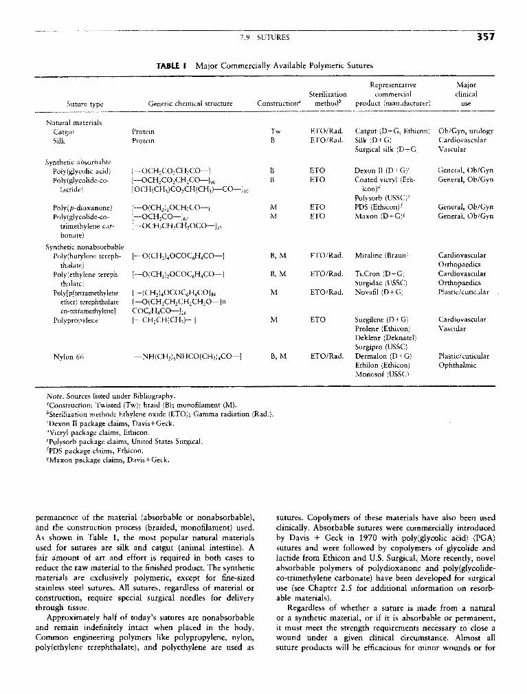
7.9 SUTURES 357
TABLE 1 Major Commercially Available Polymeric Sutures
Representative MajorSterilization commercial clinical
Suture type Generic chemical structure Construction" method^ product (manufacturer) use
Natural materialsCatgut Protein Tw ETO/Rad. Catgut (D+G, Ethicon) Ob/Gyn, urologySilk Protein B ETO/Rad. Silk (D + G) Cardiovascular
Surgical silk (D+G) Vascular
Synthetic absorbablePoly(giycolk acid) [—OCH2CO2CH2CO—] B ETO Dexon II (D+G)C General, Ob/GynPo!y(glycolide-co- [™OCH2CO2CH2CO—]90 B ETO Coated vicryl (Eth- General, Ob/Gyn
lactide) [OCH(CH3)CO2CH(CH3)—CO—]10 icon)^Polysorb (USSC)6
Poly(p-dioxanone) [—O(CH2)2OCH2CO—] M ETO PDS (Ethicon^ General, Ob/GynPoly(glycolidc-co- [—OCH2CO—]67 M ETO Maxon (D+G)* General, Ob/Gyn
trimethylene car- [—OCH2CH2CH2OCO—]33
bonate)
Synthetic nonabsorbablePoly(butylene tereph- [— O(CH2)4OCOC6H4CO—] B, M ETO/Rad. Miraline (Braun) Cardiovascular
thalate) OrthopaedicsPolyethylene tereph- [•—O(CH2)2OCOQH4CO—] B, M ETO/Rad. Ti.Cron (D+G) Cardiovascular
thalate) Surgidac (USSC) OrthopaedicsPo!y[p(tetramethylenc [— (CH2)4OCOC6H4CO]84 M ETO/Rad. Novafil (D+G) Plastic/articular
ether) terephthalate- [—O(CH2CH2CH2CH2O—]nco-tetramethylene] COC6H4CO—] 16
Polypropylene [—CH2CH(CH3)—] M ETO Surgilene (D+G) CardiovascularProlene (Ethicon) VascularDeklene (Deknatel)Surgipro (USSC)
Nylon 66 [—NH(CH2)6NHCO(CH2)4CO—] B, M ETO/Rad. Dermalon (D+G) Plastic/cuticularEthilon (Ethicon) OphthalmicMonosof (USSC)
Note, Sources listed under Bibliography."Construction: Twisted (Tw); braid (B); monofilament (M).^Sterilization method: Ethylene oxide (ETO); Gamma radiation (Rad.).cDexon II package claims, Davis+Geck.dVicryl package claims, Ethicon.Tolysorb package claims, United States Surgical.^PDS package claims, Ethicon.* Maxon package claims, Davis+Geck.
permanence of the material (absorbable or nonabsorbable), sutures. Copolymers of these materials have also been usedand the construction process (braided, monofilament) used. clinically. Absorbable sutures were commercially introducedAs shown in Table 1, the most popular natural materials by Davis + Geek in 1970 with poly(glycolic acid) (PGA)used for sutures are silk and catgut (animal intestine). A sutures and were followed by copolymers of glycolide andfair amount of art and effort is required in both cases to lactide from Ethicon and U.S. Surgical. More recently, novelreduce the raw material to the finished product. The synthetic absorbable polymers of polydioxanone and poly(glycolide-materials are exclusively polymeric, except for fine-sized co-trimethylene carbonate) have been developed for surgicalstainless steel sutures. All sutures, regardless of material or use (see Chapter 2.5 for additional information on resorb-construction, require special surgical needles for delivery able materials).through tissue. Regardless of whether a suture is made from a natural
Approximately half of today's sutures are nonabsorbable or a synthetic material, or if it is absorbable or permanent,and remain indefinitely intact when placed in the body. it must meet the strength requirements necessary to close aCommon engineering polymers like polypropylene, nylon, wound under a given clinical circumstance. Almost allpolyethylene terephthalate), and polyethylene are used as suture products will be efficacious for minor wounds or for

358 7 APPLICATION OF MATERIALS IN MEDICINE AND DENTISTRY
TABLE 2 Representative Mechanical Properties of Commercial Sutures
St. pull Kt. pull Elongation SubjectiveSuture type (MPa) (MPa) to break (%) flexibility
Natural materialsCatgut 370 160 25 StiffSilk 470 265 21 Very supple
Synthetic absorbablePoly(glycolic acid) 840 480 22 SupplePoly(glycolide-co-lactide) 740 350 22 SupplePoly(p-dioxanone) 505 290 34 Mod. stiffPoly(glycolide-co-trimethylene carbonate) 575 380 32 Mod. stiff
Synthetic nonabsorbablePoly(butylene terephthalate) 520 340 20 SupplePolyethylene terephthalate 735 345 25 SupplePoly[p(tetramethylene ether) terephthalate- 515 330 34 Supple
co-tetramethylene terephthalate]Polypropylene 435 300 43 StiffNylon 66 585 315 41 Stiff
Steel 660 565 45 Rigid
Note. Sources listed under Bibliography.
normally healing wounds. Hence, a poly(glycolic acid) suture, monofilaments and hence have an advantage in regard towhich loses strength over a 28-day period, will be just as out-of-package memory, ease of tying, and knot security if theadequate as a permanent polypropylene suture. If a patient, same knot is used for both the braid and the monofilament.however, suffers from a disease or conditions that retard Monofilament sutures tend to be more wiry out of thehealing (e.g., diabetic patients), a nonabsorbable or slower package and can become tangled up with surgical instrumentsdegrading suture may be more appropriate. Representative if the surgical team is not careful. The knot security issuemechanical properties of some commercial sutures are listed is simply addressed by using different knots or more "throws"in Table 2. of a given knot to achieve security. The major advantage
The construction of a surgical suture (i.e., braid or mono- of a monofilament suture is its relatively low tissue dragfilament) is important to both the surgeon and the patient compared with a braided suture. This low drag or frictionfor objective and subjective reasons. In addition to out-of- between the tissue and the suture allows the surgeon to usepackage tensile strength and in vivo tensile strength, the different techniques in closing wounds (e.g., continuous orsurgeon considers a variety of other parameters before making running closures). The low tissue drag is also less "abrasive"a choice of sutures for the patient. As shown in Table 3, when the suture is being pulled through the tissue. Thisthe parameters range from objective issues of knot security aspect is especially important for fragile cardiovascular, oph-or the number of knots required to secure a suture, to the thalmic, and neurological tissue, where monofilament suturessubjective issue of "feel" in the surgeons' hands. Braided are the products of choice,sutures are generally more supple products compared with
PRODUCT DEVELOPMENTTABLE 3 Suture Characteristics— ' It can take years to generate information to support clinical
Objective Subjective use of a new suture product, and usually 4—6 years for acompletely new polymer suture. The steps required to develop
Tensile strength Suppleness a suture are outlined in Table 4. Starting with the concept orKnot security Ease of tying product design, several polymers are screened prior to choosingDiameter Ease on hands the optimum candidate. In the preclinical stage, extensive safetyStrength retention anc^ animal efficacy testing is conducted to answer the questionsc, ., ... of safety and effectiveness. This testing stage can take 2—3Flexibility J . , , - • ,
years to complete. In addition to the basic requirement thatemory ou o e pac age tjle pO}ymer must be able to be extruded and processed consis-
Tissue drag tently to provide the fiber strength necessary to hold tissueInfection potentiation (wicking) together, the polymer must be able to withstand sterilization.—. Extensive toxicology testing is usually required, including

7.9 SUTURES 359
acute and chronic toxicity, pyrogenicity, antigenicity, in vitro category to Class II (SlO.k) medical devices. This change willand in vivo infection potentiation, hemolytic potentiation, mu- lead to more rapid commercialization of products and to thetagenicity, and possibly carcinogenicity. In addition, suture introduction of more generic sutures. The commercializationstrength and knot security are also evaluated in animal surgical of sutures in Europe will become more difficult overall as theprocedures. If the suture is absorbable, the in vivo tensile countries of the European Economic Community progress to-strength over time and the absorption and metabolic fate of ward a more unified approach toward registration of medicalthe polymer need to be established, devices. Previously, sutures could be commercialized in several
Following this testing, clinical evaluations are usually re- countries without registration, but future use will necessitatequired to confirm the safety and efficacy of the product. The that products meet the requirements of the CE process.subjective issues of suture handling and knotting techniques The maj°"^°u '^proprietary tech™ °gY Jat is germane
, , , j . , , , £ • to sutures is held by Ethicon, Davis + Geek, and more recentlyneed to be evaluated in the hands of many surgeons in scores , T I C r . , :; , ,. . , .
. . . , . • i - - i f • i • by U.S. Surgical. As the more traditional patents expire overor patients tor each major clinical suture use. Again, this step V r in c <. -n j «., , , . . ' . , „ , , » ' v the next 5-10 years, more manufacturers will enter an industrycan be lengthy, taking approximately 1—2 years to complete. u • i 4 u- ui •• j • j„„, .. f i - • • i- i • i i r that is already highly competitive and cost constrained.
While the clinical studies are being conducted, manutactur- C t , . , . ^ , ,Ano/ c^ j iw 1 1 1 Sutures, which once constituted 100% or t h e wound closureing scale-up studies are completed and product and package , _ - . -u . - £ • , ., ... , , _, . , , . e~ market, are now receiving stitt competition rrom surgical sta-stabihty data are assembled. I he animal satety and efficacy i u u • i j • L L. H ^ 4, ' , . , . , , , . . , i i r • piers as these mechanical devices have become well accepteddata are combined with the clinical data and manufacturing f \* u • i j • i u • n c \, . . , i by surgeons. Mechanical devices have been especially usetuldocumentation to prepare tor registration or approval by a . . . „ . . , , „ , ,
\tirr- i T-» A i • • m minimally invasive surgery and have allowed the surgeongovernment agency (e.g., the U.S. rood and Drug Admimstra- ,.c , . , .,, T» i&
v _, . • , / • , - • f to shift to laparoscopic surgery wherever possible. The removaltion). The review process itself can be time consuming, often c , „, , , , f , , ^ ^ > u - u • *t. * c, . , of the gallbladder (cholecystectomy), which is the most tre-takme more than a year. , c , 1 - 1 j -e J quently performed general surgical procedure, is now per-
formed laparoscopically in approximately 90% of the cases inthe United States. The promise of surgical glues and growth
TRENDS factors has been disappointing to date, but there are severalresearch efforts ongoing that may find the appropriate chemis-
Several factors have influenced the suture industry in the try to be both safe and efficacious.past 5 years, including the changing regulatory environment Despite these changes, one major influence remains un-in the United States and in Europe, the focus on cost contain- changed. By training, surgeons are conservative and must keepment in health care, the patent status of proprietary materials the well-being of their patient in mind at all times. As a result,and processing methods, changing surgical practice toward despite commercial or technological changes that may emergeminimally invasive techniques, and the advances in alternative over the next decade, the surgeon will need a substantial bodywound-closure technologies (staplers, glues, etc.). of clinical data before abandoning sutures. Therefore, the sci-
In the United States, most suture types have been reclassified ence and technology that support the development of suturesfrom the stringent Class III (Pre-Market Approval) regulatory will remain viable for many years to come.
TABLE 4 Steps to Develop a Suture Product
Steps Key activities
1. ConceptScreening studies Evaluation of polymers for extrusion ability and broad physical properties
2. PreclinicalManufacturing development Extrusion optimization, including fiber annealing, braidingProtocol physical testing Tensile strength, knot pull strength, diameter, sterilizationProtocol animal efficacy testing Knot security in various animal tissues, in vivo strength, handlingProtocol toxicology safety testing Acute/chronic toxicity, pyrogenicity, antigenicity, in vitro/in vivo infection
potentiation, hemolytic potentiation, mutagenicity, carcinogenicity.
3. ClinicalSafety and efficacy confirmation Clinical evaluation in representative patients (100—1000)
4. RegistrationData summary and submission Composition of preclinical and clinical dataBoard of health approval Agency review of documents and panel review (optional)
5. Manufacturing scaleup Production qualification (a few lots) and validation (many lots/sizes)
6. Commercialization Inventory stocking and promotional campaign