budget realty - scholarspace.manoa.hawaii.edu · ridge and kulepiamo~ ridge in the niu valley area....
TRANSCRIPT
• .J .
·,-.a ~-~.
,_-;i..,·· ,\.
~nn nr ... r.'llJ:y-~ ~l'r j un &H:.flbsl&:i2til
not t\l be_ taken from this room
SOILS INVESTIGATION
NIU VALLEY - HALEOLA STREET
NIU VALLEY HIGHLANDS UNIT II
TM~: 3-7-03: 72
for
BUDGET REALTY
W.O. 156
July 13, 1972
ERNEST K. HIRATA & ASSOCIATES, INC.
Soi\\.~" ndation Engineering
MUNtCI~A~~EFE~~~~2~~S CENTER
. C1ty~~~ft;~f S. King Str~et · . ~~lulu, Hawaii 900t~
ERNEST K. HIRATA & ASSOCIATES, INC. Soils and Foundation Engineering
1 f57 South King Street • Honolulu, Hawaii 96814 • Phone 531-5733
Budget Realty 1234 Kaumualii Street Honolulu, Haw~ii 96817
Attention: Mr. Richard Mew
Subject: Soils Investigation
Gentlemen:
Niq Valley - Haleola Street Niu Valley l:I.igh.lands Unit II 'f'MK: 3-7-03: 72
July 13, 1972 W.O. 156
The following report titled "Soils Investigation, Niu Valley -Haleola Street, Niu Valley Highlands Unit II, TMK: 3-7-03: 72," dated July 13, 1972, our work order 156 is enclosed.
This investigation was authorized to determine the subsurface soil conditions at the site and to determine if any unusual or adverse conditions might exist which would affect the proposed development.
This investigation was planned in cooperation with Mr. Yasuo Arakaki, Consulting Civ::il Engineer.
We found that the surface soils consisted of a gray to brown gravelly clay. This material can be considered as alluvium deposits transmitted by wind and rain towards the valley floor. The gravelly or rocky clay was found to be stiff and tight. The surface soils are considered highly expansive when water is introduced.
The site is feasible for the proposed development provided the recommendations in this report are followed.
We appreciate the opportunity to be of service. Should you have any questions, please feel free to call on us.
Very truly yours,
Ernest K. Hirata & Associates, Inc.
-c~~64.4 Ernest K. Hirata
EKH: ph

TABLE OF CONTENTS
Page INTRODUCTION. • . • . . . . . . • . . . . . . . . . . . . . . . . . . . 1
SITE DESCRIPTION. . . . • • • • . . • • . . . • • • • • • . • • • • 1
PROPOSED GRADING ..••.•.•..••• ·. • • • • • . • • . . . . 2
FIELD EXPLORATION. . . . . . . . • . . • . • • . • • . • . . . . . 2
SOIL CONDITIONS. . . . . . . . • • . . . • . • . • • • • • • . . • • . 3
LABORATORY TESTING ....•.•..•..•.•...••. • • . 3
CONCLUSIONS AND RECOMMENDATIONS........... 4 l
APPENDIX
Appendix of Laboratory Testing
Standard Grading Specifications
PLATES
Log of Borings
.Consolidation Test Report
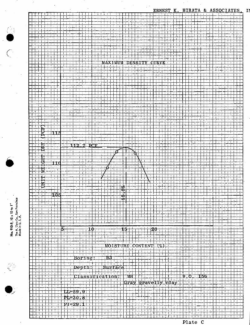
Maximum Density Curve
Laboratory Test Results
Preliminary Grading Plan
Page 1 and 2
Page 1 through 6
Plates Al through A9
Plates Bl through B3
Plate C
Plate D
SOJLS INVESTIGAT.ION
NIU VALLEY - HALEOLA STREET
NIU VALLEY HiGHLANDS UNIT ii
TMK: 3-7-03: 72
INTRODUCTION
This report presents the results of our soils investigation
conQ.ucted on the subject property. The scope.of this
investigation was planned in collaboration with Mr. Yasuo
Arakaki, Consulting Civil Engineer. This investigation
was authorized to detenn::i.ne the subsurface soil conditions
at the site ~nd to provide preliminary recommendations for
the residential development.
SITE DESCRIPTION
The proposed site is located in the valley between Hawaiiloa
Ridge and Kulepiamo~ Ridge in the Niu Valley area.
The site extends approximately 1500 feet from the end of
Haleola Street. A former river bed bisects the proposed
subdivision irt half a1ong the length of the subdivision.
A graded road extends along the western half of thiS site near
where the proposed extension of Anolani Street is to be built.
Large boulders were observed over the entire site, and
especially in the area of the proposed channel. The entire
area has heavy growth of halekoa trees and California grass.

Page 2 W.O. 156
Groundwater was not encountered in any of the exploratory
borings nor was surface water observed anywhere on the site.
PROPOSED GRADING
The proposed development will include 61 residential lots.
Based on the preliminary grading plan, grading fo:r the western
half of the site will be limited primarily to the extension
of Anolani Street. The maximum height of cut slope is expected
to be approximately 30 feet in the rear of lots 56 through 58.
On the eastern half of the site, fill will be placed extensively
on the downhill side of the extension of Haleola Street.
Approximately 10 feet of fill will be placed in the lots adjacent
·e to the proposed channel.
·Grading will also be necessary for the proposed 0.3 M.G.
Reservoir.
FIELD EXPLORATION
Field exploration was performed on June 27 and 28, 1972 using
a truck mounted rotary auger driil rig.
A total of 9 exploratory borings were drilled ranging in depth
froiil 4.0 to 18.75 feet. The soils were continuously logged by
our field engineer and classified by visual examination in
accordance with the Unified Soil Classification Syste1Jl.

• Page 3 w.o. 156
Undisturbed and bag samples were recovered from the borings for
laboratory testing. Undisturbed samples were obtained by
driving a thin walled steel sampler with a 140 pound hanuner
from a height of 30 inches. The required blow count for each
6 inches of penetration is shown on the enclosed "Boring Logs,"
Plates Al through A9.
SOIL CONDITIONS
The surface $Oils consisted of a gray to brown gravelly clay.
This material can be considered as alluvium deposits transmitted
by wind and rain towards the valley floor. All borings
encountered numerous cobbles and boulders in the alluvium
materiai.
The gravelly or rocky clay was found, to be stiff and tight.
Laboratory tests indicate'that the clay is highly expansive
when water ;is introduced.
All of the borings encountered cobb1es and boulders, and
difficulty was encountered in recovering samples.
LABORATORY TESTING
Laboratory testing was performed on the un.d:tsturbed and bag
samples to determine their strength characteristics and
engineering properties. Laboratory tests included Atterburg
Limits, moisture density relationships, consolidation,
compaction, swells and :remolded swells. Test results and
testing procedures are described in the attached Appendix.

e CONCLUSIONS AND RECOMMENDATIO~UL
A. Slope Stability
Page 4 W.O. 156
It is our opinion that the subject property can be safely
developed utilizing a maximum slope gradient of 1i:1 for
cut slopes in the gravelly clay. A slope gradient of
2:1 may be used for fill slopes. For those cut slopes
where hard basaltic rock is encountered, slope gradients
of 1:1 may be used.
Du~in~ grading, all loose boulders should be removed from
areas above the proposed grading areas to prevent the
:possibility of damage to future homes.
To minimize the effects of erosion and weathering, all
slopes should be planted as soon as practical upon
completion of grading.
B. Groundwater
Groundwater was not encountered in any of the borings and
the need for subdrains is not anticipated.
C. Bearing Capacity
Slab type foundations will not be feasible due to the
expansiveness of the soil, and therefore post and beam
type construction should be considered. An allowable
bearing value of 2000 pounds per square foot may be used
for footings having a minimum width of 12 inches and a

Page 5 W.O. 156
minimum embedment of 12. inches in both cut and fill.
However for foot.ings located on slopes, the embedment
should be 24 inches.
D. Lateral Pressures
An equivalent fluid pressure of 50 po'IJ,nds per'cubic foot
per foot of depth may be used in the design of retaining
walls and channel walls.
E. Settlement of Fills
Data obtained from the exploratory borings indicate that the
gravelly clays are in a stiff condition, aru:l settlement
from placement of fills is expected to be negligible.
F. Expansive Soils
The results of the loaded swell tests indicate that the
surface gravelly clays are highly expansive. Special
foundation design will be necessary to prevent damage to
slabs on grade such as garage slabs.
The upper two feet under slab should be replaced w:i,.th
non expansive material. In addition slabs should be
reinforced with 6x6 - #10x#10 welded wire mesh located in
the center of the slab.
G. Grading
Rippability: The onsite soils encountered during our
investigation indicate that excavations can be made with

Page 6 W.O. 156
conventional earth moving equipment. However area~ above
the proposed roads may consist of basaltic rock and
blasting may be required. In addition, large boulders
may be encountered wh~ch may require blasting.
Insitu Moisture Content: The insitu moisture of the soils
encountered will require air drying in order to achieve
proper compaction.
Our mini~um Grading Specifications are attached and shall be
considered a part of the recommendations except where specifi-
cally superceded in the text of this report ..
1. All heavy vegetation snail be stripped and wasted from
the site.
2. Oversize material shall not be placed within 5 feet of
finish pad grade nor piaced within 10 feet of any
slope face.
3. All fill shall be placed and compacted to at least
90% relative compaction using Modified AASHO 7-180
laboratory test.
H. Pave~ent Design
Pavement design recommendations will be submitted in an
addendum report upon completion of grading.
Respectfully submitted,
Ernest K. Hirata & Associates, Inc.
APPENDiX OF LABORATORY TESTING
Classification
The field classification is verified in the laboratory, also ·
in accordance with the Unified Soil Classification System.
Laboratory classificat.ion·is detei'mined by both visual
examination a:ttd Atterburg Limit Tests according to ASTM D423
and D424. The final classification is shown on the Boring Logs.
Moi~:t:u..I"e-D~n13ity
The field moisture content and dry unit weight are determined
for each of the Undisturbed soil samples. The information is
us~fql in providing a gross picture of the soil consistency
between borings and any local variations. ·The di"Y unit weight
is determined in poUnds per.cubic foot while the moisture
content is determined as a percentage of the dry unit weight.
These samples are obtained from a 3" O.D. split tu'be ~;~pler.
Con$olidation
Settlement predicti'ons of the soil's behavior under load are
made on the basis of the consolidation tests. Loads are
applied in several. increments in a geometric progression, and
the resulting deforDJ,ations are recorded at selected time
intervals. Porous stones are placeq in contact with the '.
top and bottom of each specimen having an inside diameter of
2.40 inches and a height of 1 inch to permit addition and
\
.~·
release of pore fluid. Results of undist:urbed and remolded
samples are plotted on the Consolidation Test Report.
/
CompactiQ~ Test§
Compaction tests were performed on bag samples to qetermine
the optimum moisture content at which each type of proposed
fill mater:ial CQJJJ.pacts to 100% density. The tests were
performed according to the Modified AASHO T-180.
Swell Te~ts
Swell tests were performed to determine the expansiveness of
the onsite surface soils. The tests were performed on undis
t\lrbed ring and remolded samples taking a one inch high spec
imen under different surcharge loads.
Shear Test$
Shear tests are performed in the Direct Shear Machine which
is of the strain control type. The rate of deformation is
approxilJl,ately 0.03 inches per m,inute. Eacb sample is sheared
under varying confining loads in order to determine the Coulomb
shear strength paran1eters, cohesion a11d angle of internal
friction. Eighty percent of the ultimate value is taken to
determine the shear strength parameters.
Page 2
ERNEST K. HIRATA & ASSOCIATES INC.
STANDARD GRADING SPECIFICATIONS
These specifications present the usual and minimum requirements for grading operations performed under the control of Ernest K. Hirata & Associates Inc.
No deviation from these specifica.tions will. be allowed, except where specifically superseded in the preliminary soils report, ·or in other written communication signed by the Soils Engineer.
I. GENERAL
A. The Soils Engineer is the Owner•s or Builder•s representative on the project. For the p~pose of these specifications,· supervision by the Soils Engineer includes that inspection performed by any person or persons ernployed by, and responsible to, the licensed Civil Engineer signing the soils report.
B. All clearing, site preparation or earthwork performed on the pro1ect shall be conducted by the Contractor under the supervision of the Soils Engineer.
C. It is the Contractor•s responsibility to prepare the ground surface to receive the fills to the satisfaction of the Soils Engineer and to place, spread, mix, water and compact the fill in accordance with the specifications of the Soils Engineer. The Contractor shall also remove all material considered unsatisfactory by the Soils Engineer.
D. It is also the Contractor•s responsibility to have suitable and sufficient compaction equipment on the job site to handle the amount of 'fill being placed. If necessary, excavation equipment will be shut down to permit completion of compaction. Sufficient watering apparatus will also be provided by the Contractor, with due consideration for the fill material, rate Qf placement and time of year.
E. A final report shall be issued by the Soils Engineer attesting to the Contractor•s conformance with these specifications.
Standard Grading Sp~cifications Page 2
e. II. SITE PREPARATION
A. All vegetation and deleterious material such as rubbish shall be disposed of off~ite. This removal must be concluded prior to placing fill.
B. Soil, alluvium or rock materials dete~mined by the Soils Engineer as being unsuitable for placement in compacted fills shall be removed and wasted from the site. Any material incorporated as a part of a compacted fill must be approved by the Soils Engin~er.
C. After the grolJ!ld surface to receive fill has been cleared, it shall be scarified, disced or bladed by the Contractor until it is uniform and free from ruts, hollows, hummocks or other uneven features which may prevent uniform compaction.
The scarified ground surface shall then be brought to optimum moisture, mixed as required, and compacted as specified. If the scarified zone is greater than twelve inches in Q.epth, the excess shall be removed and placed in lifts restricted to six inches.
Prior to placing fill, the ground surface to receive fill shall be inspected, tested and approved by the Soils Engineer.
D. Any underground structures such as cesspools, cisterns, tunnels, septic tanks, wells, pipelines or others not located prior to grading ar~ to be removed or treated in a manner prescribed. by the Soils Engineer.
III. COMPACTED FILLS
A. Any material imported or excavated on the property may be utilized in the fill, provided each material has beep determined to be sui tab.le by the Soils Engineer. Roots, tree branches and other matter missed during clearing shall be removed from the fill as directed by the Soils Engineer.

Standard Grading Specifications Page 3
B. Rock fragments less than six inches in diameter may be utilized in the fill, provided:
1. They are not placed in concentrated pockets.
2. There is a sufficient percentage of fine-grained material to surround the rocks.
3. The distribution of the rocks is su~ervised by the Soils Engineer.
c.· Rocks greater than six inches in diameter shall be taken offsite, or placed in accordance with the reconunendations of the Soils Engineer in areas designated as suitable for rock disposal.
D. Material that is spongy, subject to decay, or otherwise considered unsuitable shall not be used in the compacted fill.
E. Representative samples of materials to be utilized as compacted fill shall be analyzed in the laboratory by the Soils Engineer to determine their physical properties. If anY material other than that previous-
. ly tested is encountered during grading, the appropriate analysis of this material shall be conducted by the Soils Engineer as soon as possible.
F. Material used in the compacting process shall be evenly spread, watered, processed and compacted in thin lifts not to exceed six inches in thickness to obtain a uniformly dense layer. The fill shall be placed a_nd compacted on a horizontal plane, unless otherwise approved by the Soils Engineer.
G. If the moisture content or relative density varies from that required by the Soils Engineer, the Contractor shall rework the fill until it is approved by the Soils Engineer.
H. Each layer shall be compacted to 90 percent of the maximum density in compliance with the testing method specified by the controlling gove~nm~ntal agency.
Standard Grading _Specifications Page 4
If compaction to a lesser percentage is autho~i?ed by the controlling governmental agency because of a SJ?ecific land use or expansive soil conditions, the area to receive fill compacted to less than 90 per-
/ cent shall eithe~ be c].elineated on the grading plan or appropriate reference made to the a~ea in the soil report.
I. All fills s}lall be keyed and benched through ail topsoil, colluvium, alluvium or creep material, into sound bedrock or firm material where the slope receiving fill exceeds a ratio of five horizontal to one vertical, in accordance with the recommendations of the Soils Engineer.
J. The key for side hill fills shall be a m1.n1mum of 15 feet within bedrock or firm materials, unless otherwise specified in the soils report.
K. Drainage terraces and subdrainage devices shall be constructed in compliance with the ordinances of the controlling governmental agency, or with the recommendations of the Soils ~ngineer.
L. The Contractor will be required to obtain a minimum relative compaction of 90 percent out .to the f·inish slope face of fill slopes. This may be achieved by either overbuilding the slope and cutting back to the cornpC\cted core, or by direct compaction of the slope face with suitable equipment, or by any
. other procedure which produces the required compaction.
If a method other than overbuilding and cutting back to the compacted core is to be employed, slope tests will be made by the Soils Engineer during construction of the slopes to determine if the required compaction is being achieved. Where failing tests occur or other field problems arise, the Contracto~ will,. be notified of such conditions by written communication from the Soils Engineer in the form of a conference memorandum, to avoid any misunderstanding ar:i,.sing from oral conununication.

Standard Grad~ng Specifications Page 5
e If the method of\achieving the required slope compaction selected by the Contractor fails to produce the necessary results, the Contl;:'actor shall rework or rebuild such slopes until the required degree of compaction is obtained, at no additional cost to the Owner or Soils Engineer.
M. All fill slopes should be planted or protected from el;:'osion by methods specified in the soils report.
N. Fill ... over-cut slopes shall be properly keyed through topsoil, colluvium or creep mate:rial into rock or firm materials; and the transition shall be stripped of all soil prior to placing fill.
IV. CUT SLOPES
A. If any conditions not anticipated in the preliminary report such as perched water, ?ee:page, lenticular or confined strata of a potentially adverse nature are encountered during grading, these condi-tions shall be analyzed by the Soils Engineer; and recommendations shall be made to treat these problems.
B. Unless otherwise specified in the soils report, no cut slopes shall be excavated higher or steeper than that allowed by the ordinances of controlling governmental agencies.
c. . Drainage terraces shall be construct;.ed in compliance with the ordinances of controlling governmental agencies, or with the recommendations of the Soils Engineer.
V. GRADING CONTROL
A. Inspection of the fill placement shall be provided by1 the Soils Engineer during the progress of grading.
B. In general, density tests shall be made at intervals not exceeding two feet of fill height of every 500 cubic yards of fill placed. This criteria will vary

~
Standard Grading Specifications Page 6
depending on soil conditions and the size of the job. In any event, an adequate number of field density tests shall be made to verify that the required compaction is being achieved.
c. Density tests shall also be made on the surface material to receive fill as required by the Soils Engineer.
D. All cleanout, processed g~ound to receive fill, key excavations, supdrains and rock disposal must be inspected and approved by the Soils Engineer prior
:.. to placing any fill. It shall be the Contractor's responsibility to notify t:.he Soils Eng.i,neer when such areas are ready for. inspection.
VI. CONSTRUCTION CONSIDERATIONS
A. Erosion control measures, when necessary, shall be provided by the Contractor during grading and prior to the completion and construction of permanent drainage controls.
B. Upon completion of grading and termination of inspections by the Soils Engineer, no further ;Ei.lling or excavating, including that necessary for footings, foundations, large tree wells, retaining walls, or other features shall be performed without the approval of the Soils Engineer.
C. Care shall be taken by the Contractor during final grading to preserve any be:tms, drainage terraces, interceptor swales, or other devices of a permanent nature on or adjacent to the property.
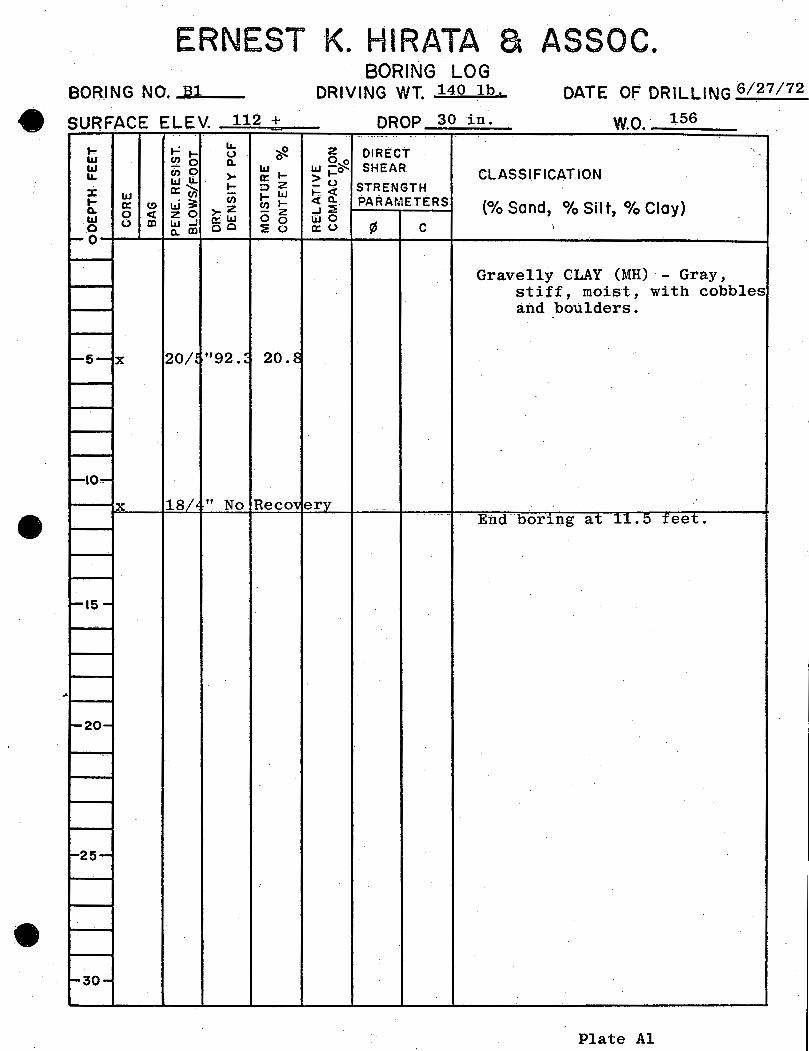
ERNEST K. HIRATA a ASSOC. BORING NO. ~B~l __
e SURFACE ELEV 112 + . ...
~ ...,: LL ~
IIJ en I- 0 0 IIJ
...... 0 0. ~ ... ci)9 LL W LL · >-
a:~ .... ::::>2 X w .... w .... a: (,!) w3: en en I-0. 0 ..:t: zo >-~ - z w 0 OJ w.J gso 0 0 0 Q.Dl ~ (.)
~o
1--5- X 20/. "92.~ 20.8
f-lO..-
X 18/t " No Recov
~15-
-20-
~25-
~ao-
BORING LOG DRIVING WT. 140 lb. DATE OF DRILLING 6/27/72
DROP 30 in . wo. 156 . ···--
2 DIRECT '· 0~ SHEAR W i=O CLASSIFICATION ~0 STRENGTH 1-::..:t:
PARAMETERS o(t;Q. (0/o Sand, 0/o Silt, 0/o Clay) .J ~-
l.LIO ¢ a:o c I
Gravelly CLAY (MH) - Gray, stiff, moist, with cobbles and boulders.
erv End· bor·1ng at 11.5 feet.
Plate Al

ERNEST- K. HIRATA a ASSOC. BORING NO • .....:B=2~
e SURFACE ELEV 160+ . t- ..,_; lL
~ 0 w (f)t-~
0 w - 0
~ .... (1)0 lL LLJI.L. >-t- :::>Z
X w a:'(f;- - )-LLI t- w~
(f) 0.. a: C) ,_z (f) 1-
0 <t zo - z w 0 m LLJ..J a:LLJ 0 0 0 ~ CD oo :!: (.)
1--0
1--5-
~10-
1-15-
1-20-
~25-
-30-
BORING LOG DRIVING WT. 140 lb. DATE OF DRILLING 6/27/72
. -- . • ---DROP 30 in wo 156
z DIRECT Oo
lLJ ,...(i: SHEAR CLASSIFICATION >I-_(.) STRENGTH - 1- <{ <[~ PA~~~ETERS ..J~ (
0/o Sand, 0/o Silt, 0/o Clay) wo ~ a:u c
Gravelly clay (MH) - Grayish brown, boulder from 1 foot.
End boring at 4 feet. Cannot penetrate.
!
~
:
;
;
---
Plate A2

ERNEST 1<. HIRATA a ASSOC.
BORING NO. B3
tt SURFACE ELEV . 170+ . .... t-= 11.
~ liJ (/)I- 0 0 liJ - 0 0.
~~--(1)0 11. w"- >-
1- :::>Z X: liJ 0::~ t-W .... 0: ~ w~
(/) (/) ~
0. 0 c:t zo ,_z - z ILl 0 CD W...J o::W 0 0 0 0. CD oo ~0
1--0
X 49 No li ecove
1--5-
X ~3/~ "83.1 45.1
1-10-
x-~0/~" Nc Reco
1--&5-
'-20-
1-25-
-30-
BORING LOG DRIVING WT. 140 1 h DATE OF DRILLING 6127/72
DROP 30 in wo 156 .. ~ .
z DIRECT Oo w ,....()' SHEAR CLASSIFICATION >I-
_(.) STRENGTH 1-c:t c:t0. PARAMETERS
(0/o Sand, 0/o Silt, o/o Clay)· ...J~
wo ~ 0::<,) c
Gravelly CLAY (MH) - Gray, moist, stiff; with
ry cobbles.
trery End boring at 12 feet.
Plate A3
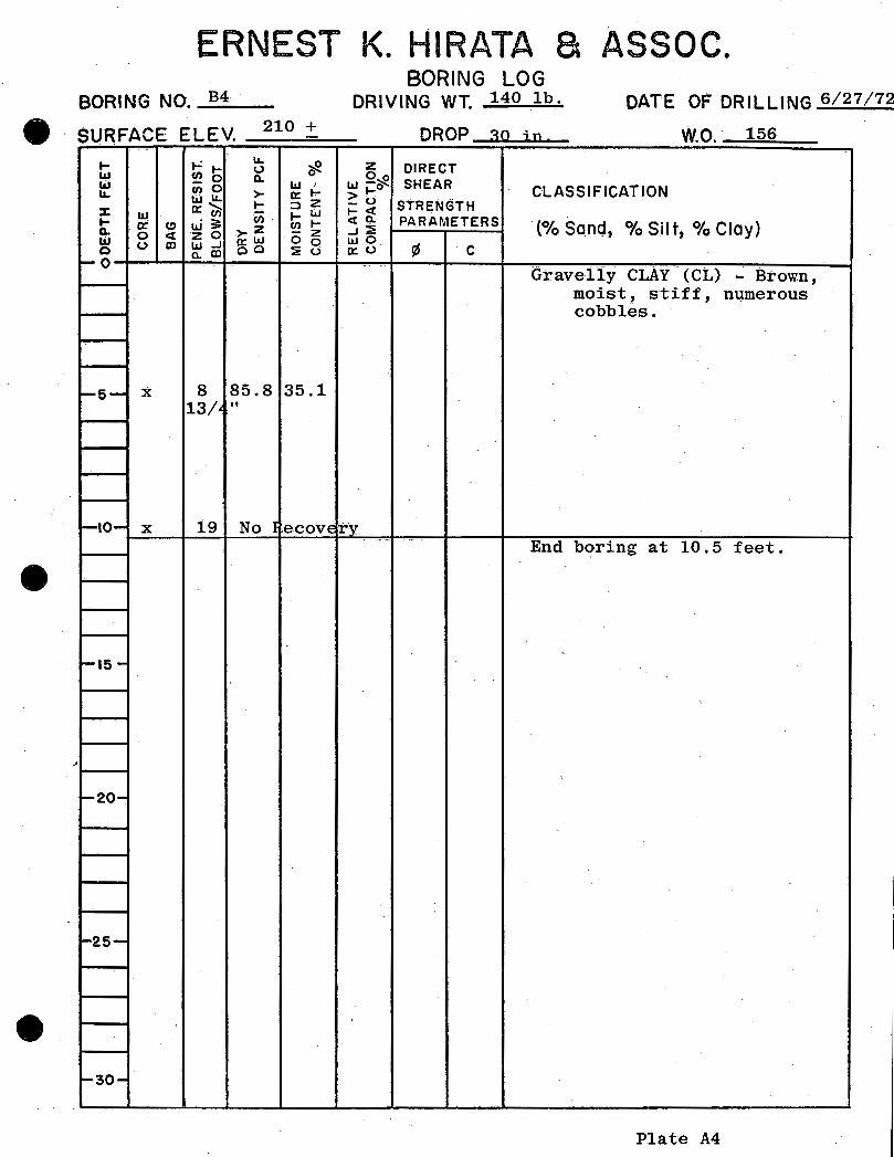
ERNEST K. HIRATA a ASSOC. BORING NO. _B_4 __
e SURFA"'E ELEV 210 + "" -1- ..,.: ~
~ <.) w U)l-Q. 0
w - 0 W' U)0 IL w~ >- 0: 1-
1- ;:)Z X w o:U) ..;,;, 1- w 1- a= (!) tJ;; U)
(/) ..... Q. 0 <t zo ,..z - z liJ (.) Q) w...J Q:W 0 0 0 a:.m co :.;;: (.)
t-O
t-5- X 8 85.8 35.1 13/• "
1-10- X 19 No I ecove
t-15-
..
'-20-
-25-
'-30-
BORING LOG DRIVING WT. 140 lb · DATE OF DRILLING 6/27/72
DROP ~o ;n wo. 156 0
z DIRECT w 2~ SHEAR 1-0 CLASSIFICATION ~(.) STRENGTH 1-C:t eta:. PARAMETERS
·(0/o Sand, 0/o s i I t, 0/o cIa y) ...J~
we ¢ o:u ·c :
-- - --Gravelly cLAY- (CL) - Brown,
moist, stiff, numerous cobbles.
i'y -- -· - .
End boring at 10.5 feet.
'
-'
Plate A4

ERNEST K. HIRATA a ASSOC. BORING NO. _B_..5 __.__
4t SURFACE ELEV 99+ -•
t- . t-= t- IL ~ u w ~0 0.. 0
w cno w IL. La.JIL > a: t-
t- ::>Z ::z:: w a:~ t-la.J t- w?J: Cf)
0.. « (!) >z (/) t-0 <t zo - z w 0 ID laJ ...J a:La.J 0 0
0 0.. ID oo :i u ~0
l-5- X 17 No ~ecov«
1-10-
X 10 111.~ 10.:
1-15-
-20-
1-25-
f-30-
BORING LOG DRIVING WT. 140 lb · . DATE OF DRILLING 6/28/72
. .. DROP 30 in. wo 156
z DIRECT 0~
LaJ j:o SHEAR CLASSIFICATION :::u STRENGTH t-<t <tO.. PARAMETERS ...J~ (
0/o Sand, 0/o Silt, 0/o Clay) La.JO
¢ a:o c
Gravelly CLAY (MH) - Gray, .moist, stiff, numerous cobbles.
ry
c
End boring at 13 feet.
l
!
. '
Plate A5
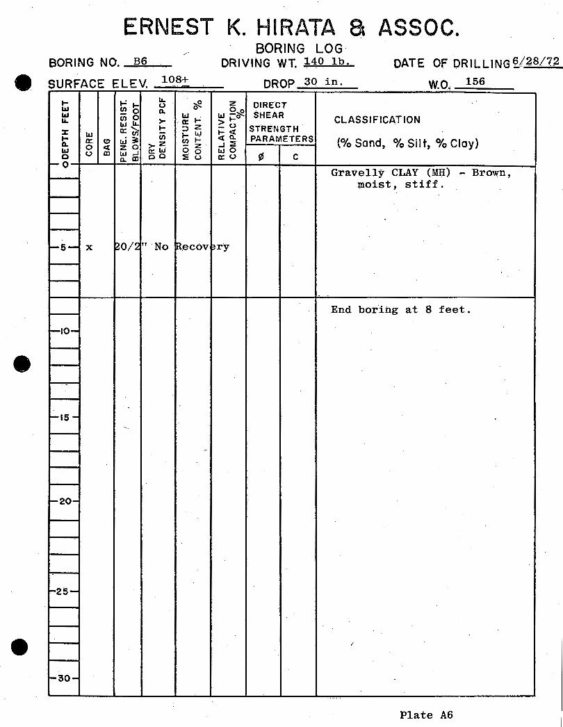
ERNEST K. HIRATA a ASSOC. BORING N 0. --=B;.;;;,6__... ....
SURFACE ELEV 108+ . ... .,_; LL
~ 1.1.1 (/)I- 0 0 w - 0 0.. w . LL (1)0 >- '0: ... wLL 1- :::>Z X w 0:~ 1- LLJ ... w3: (/)
0.. 0: (!) >-z (/) 1-0 ct zo - z w 0 CD t.a.J-1 o:t.a.J oo
0 o.CD oo :!:o 1-0
1-5- X ~0/~" No IRecov
1-10-
1-15-~
-
1-20-
-25-
-30-
BORING LOG DRIVING WT. 140 lb. DATE OF ORILLING~~8/72
DROP 30 in. wo 156 ·-
z DIRECT Oo
Iii~~ SHEAR >I- CLASSIFICATION -0 STRENGTH l-et ~0. PARAMETERS
{0/o Sand, -l:E 0/o Silt, 0/o Clay) wo
¢ 0:0 c Gravelly CLAY (MH) - Brown,
moist, stiff.
~ry
End bor1ng at 8 feet.
/
..
Plate A6

ERNEST K. HIRATA a ASSOC. BORING NO • ...:B:;..:7 __
tt SURFACE ELEV 132 + . ... r: ... lL
~ 0 IIJ g?o a. 0 IIJ cnO ~ ..... ..... WlL >-
!:: :::>Z % IIJ rx:~ ... w ... 0: (!) w3: en en 1-0. 0 c( zo >-z - z ·w 0 m w...J a:W 0 0 0 a.m oo :i! 0
~o
X 8 92.6 27.5 21
f-5-
X ~3/C" No IRecov - ----
~10-
l-IS-
f,-.20-
1-25-
1-30-
60RING LOG DRIVING WT. 140 lh DATE OF DRILLING 6/28/72
DROP 30 in I . . wo. 156 ------·
z OIRECI Oo w -o-:: SHEAR CLASSIFICATION >I-...... u STRENGTH 1-c::(
c(Q.. PARAMETERS (0/o Sand, 0/o Silt, 0/o Clay) ...J~
wo ¢ 0::0 c
·-- -- . - . ·----
Gravelly CLAY (MH) - Brown, moist, very stiff, nUm.erous cobbles.
~ry
End, boring at 8 feet.
I
--·-
Plate A7
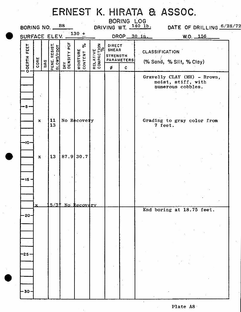
ERNEST K. HIRATA a ASSOC. BORING NO. _a_s __
SURFACE ELEV . 130 + . ... ~
IL. ~ w (/).,.. (.) 0
w -- 0 Q.
w t-cnO IL. w"- >- 0::.
X 0::~ ... ::>Z w ~~ t; 0:: (!) w~
(/)
0 <t zo >-z - z w (.) co w ...J o:::W 0 0 0 a:. co oo ·::!! (.)
1-0 .. ~
\
~s-
X 11 No .R cove 13
r-ao--
X l3 87.9 30.7
i-15-
X 5/3 I No eCOVE
f-20-
1-25-
1-30-
BORING LOG DRIVING WT. 140 lb · DATE OF DRILLING 6/28/72
DROP 30 in I . . wo 156 ~ ~ . ~ ~ .
z DIRECT w 2~ SHEAR 1-0 CLASSIFICATION !::u l-et STRENGTH r PARAMETERS eta.
(0/o Sand, 0/o s i I t t 0/o cIa y) .J~
liJO ¢ c 0:::0
Gravelly CLAY (MH) - Brown, moist, stiff, with numerous cobbles.
y Grading to gray color from 7 feet.
.
rv End boring at 18.75 feet.
Plate AS

ERNEST K. HIRATA a ASSOC. BORING NO. _B_9 __
e SURFACE ELEV 210 + . ... r: lL
~ (/) ..... 0 w 0. 0
w - 0 ~ ... (1)0
"- wu. >-1- ::>Z :z: w a: "(I) (/) I- LLI ... a: (!) u.i~ (/) 1-
Q. 0 <t zo ,..z - z w Q:LLI 0 0 0 (.) Ol LLI ..J oo ::iE 0 Q. IX) -.o
l-5- X 14 84.1 29.8 26 23/ r:>"
1-10- X 11 86.5 35.1 11 16
~•s- x- 5/1' No ~ecov
-20-
~25-
-
'-30-
BORING LOG DRIVING WT. 140 lb. DATE OF DRILLING6/28/72
DROP 30 in . . . wo 156 - ----- - ---
z DIRECT Oo
w -~ SHEAR CLASSIFICATION >I--0 STRENGTH ~~ PARAMETERS
(0/o Sand, 0/o Silt, 0/o Cloy) ..J~
wo a:O ¢ c
---- - ·-- ---· -· - --
Gravelly CLAY (?.1H) - Gr~yish brown, moist, stiff, numerous cobbles.
'
\
\
ery End boring at 15 feet.
Plate A9


ERNEST K. HIRATA & ASSOCIATES, Il ---
-- ·-·-· ---- -· - --· -- ----- ·-·
0.1 0.2 0.3 0.4 0.5 1 2 3 ~ 5 10 20 25
+6 I ~ .... .... r-.~ +5
~ "-r-r--""G ........
0 +4 - ~
·ri - - r-.. --+J +3 ~ -~
* •ri +2 M 0 til +1 ~ 0 0 0
*' -1 N
-2 ----
- -
-- --
0.1 0.2 0.3 0.4 0.5 l 2 3 4 5 10 20 25
Pressure, p, Kips per sq. ft.
Type or Specimen Undisturbed
Dia.m 2.40 in. Ht
Overburden Pres sure, Po
Preeonsol. Pressure, Pc __
Compression Index, Cc
Classification
LL
PL --
Re'liii!Lrks*Wa ter
I
ENG FORM tM4YU 2090
MH --
G B
Dl.O
added
1.0 in.
- T/sq :tt ---
T/sq 1't
at 700 PS:E
-
Bef'ore Test After Test
Water Content, v0 27.5 ~ vf' 38.5 ~
Void Ratio, e0
ef
Saturation, S0 ~ sf - ~
lb/:tt3 --
Dry DeiiSi ty, 7 d 92.6 ~ ~~ot e
0 .. X 10- em/sec
Project Niu Valley Highlands Unit II
Budget Realty
Area W.O. 156
BoriDg No. B7 Sample Ro.
Depth 2' 7-3-72 El Date --
CONSOLIDATION TEST REPORT
0 1424
.. --Plate. B2 __ . ·- . ..... . --··----·-.

r
ERNEST K. HIRATA & ASSOCIATES, IIi - --·
--
------ - --- . ------·-· ---
0.1 0.2 0.3 0.4 0.5 1 2 3 4 5 10 20 25
--
-
-. ·--·
s:: 0
"" """
0 -~
"" -1 ....... -u-0 -2 Ul s:: 0 tJ
~
'
-
0.1 o.2 0.3 o.4 o.5 l 2· 3 4 5 ~0 20 25 Pressure, p, Kips per sq. ft.
- -- --- --Type ot Specimen
R&:>mnln&:>n
Diam 2 40 in. Bt 1.0 i_n.
Overburden Pressure, Po
Precoosol. Pressure, Pc
Compression Index, Cc
Classification
LL
PL
Remrks
ENG FORM I MAYU
No
2090
MH
G .S
DlO
water
T/sq :tt
T/sq :tt
..
--·--
added
-
Be:tore Test Af'ter Test .. ~ -
Water Content, v0_ 1~ .0., v:t ., Void Ratio, e
-- 0_ e:t
Saturation, S 0
., st ., Dry Density 1 7 d 112. 6lb/rt3
~Oat e0 = X 10• em/sec
Project N;,, V<:>11ou Hiahll'lnn!=:: TTnit: TT
\ Bude:et Real tv
Area W.O. 156
Boring No. B3_ Sample No. -- . - -
Depth Surface 7-3-72 El Date
CONSOLIDATION TEST REPORT
0 8424
. --1Hate B3_ ...
ERNEST K. HIRATA & ASSOCIATES IN I I ; r i I I ! I i ' I j
! I I I I I i I I_ I I I t ! l_! I i I 1
1.. ! T .. :·.x·· t_! I I i i
i I ! ; __ ! __ . I ! l I ·I ! I j ~ _ i I i l ! i ! I I ' i i l I I I ' ! 1 I t I
I I i ! ! i ! j i ! I ! I f i
I I I i 1 ! ! I j I I i 1 1 ; 1 1 , i r [ I ! { I i ' I I I ! j_ i I i I I I I
I : i I ·1 I - -; I _LL r:1 I I I 1 I I I ! I ,- -, I I I !_ 1 i I I I 1 .I
I ' i. I ' I - l __ i_) I I I I : I 1· 1 1 i • I 1
I I i. -, i ; I i I , ' ! . _! I I ' ! I I t l !
I I i I I I i i , I ! I l i ! I I
I ; _I L I I I • i i I i ! I [ I [ ' i ' i I i ! : ! I I i I I
! ' ' I I I I ; I l
I ! I i i I i I I_ 1 I [ I I
I i I ! I j I : I i ! ! ! .. ! I ·I I I I I ! I I ! I ! ! 1 : I 1. I i I ' I I
'_[ ! i I ! ' ! I I i _j I I ! l I I I I i
i j I IiI I' I I I i ! J '
I i ' I - i I ! I I l I I I I i ' ' I I I -~ I
f I I : ! 'i I I t i I~ .I I ~ ! I I i---r-T I I I I I I t i_'j' I-~- t t I j I I !
i : I }:". l ' I I I I i i l ! i ! I
' .. ' I 1 I I I i ' ' I I i I ' I I i ! i I I I I I I I I 1 I j I
i I I I I I I I I 1 ' I i.- __ I_ I ! 'j ( 1 ' i ! !
I ' . '!:: ' ' I i j
! ~' ·- !. I j I I J ; (!1 •">'. I I ! I 1 I I I I I I I I I I 1
' ! I ! I ' I A. i I I ~ I !\I 1 ,--I . I ! l I I ! I I 1 I I
· i I ' . if, ' I I ' ! '\1 ---'----1--t-H-t! -+-1 +--i-t--t-!--iri-+-+1 -i-...:,_-t--t-.._;----:1_. I ,_, -,'r+--+---1 rf-1 ~~ I I I .I I \ ' I r!rm ~~r.~-.., ;._·----'-, --,---·-r---,1 _,.., -.;--, +--r,-t.---:---"---'--+-, _;:c.. -1.1--'t'-tl--:_t, -::-:-,,_---;~~:f/;-;.1~1-=-t-=-t-=-t-::;~~'=.1f:_1--:_t' ~I-_fi·_-+L'~-~;"~J-i-t--1 -=,t~~i1
'=.1-:-:_-;_; -::,':.1,-:_t~~~4r-1 _-1.._~-:_t-:_~~~4f:_1-=_t~~-_f11
--.,;.1~--;+l1
-:_t~t-::,+--:_t±:J±~ . -' .. ' ! I I I ! ! : ( I \ l I 1 I !. i I
' i I ! I ! i ., I ! ' I T' !
~t-fJ~·:--:~~--~~-·-~~--~--~~~:-·II~~~~-i--~,-+~~-r~~~~-+-~~~~~~-+~~-~-~:~;_1~-+~~+-+-~~---~-+~l~l~l-+-+-~-r~:--t-+-·~!~l ~,--+~1 I I _L J • I 1 1· i I 1
~~-~,~-+-+-+~11~~~.~~~ ~-~~~~~.-~~-_--i,-+-+-+;_~--~,~~~~:-+,-+-+--~~-~+-+1 -+!~~,.~.~-+-+-+-, ~,-+-r-r~t-t-!---1~-t-t-r-r+-·t-+-+1-+-l_~,l"-4-+,-~,-+-~ I I I i I i ' ' I I i ; I I I I l
! i I I i I I I I . : ! I J I i I ! _; l ; I I !. I f I I • I I ! i I ! I I } I J i ! I j I I I
! ! ! I I ' I I : I I i 1
I I l I ! ! i I ! I t I ! i I ! ! I ! I I ! ' I
I ! 1 ! I 1 1 1. t 1 ; 1 1 i ! 1 1 , 1 i r 1 ; i 1
! ! I I ! I I .1. I I I I I ! I I I I j_l I I ~!--1~~-+'-+1 -+~-+1-~-----r-~~1-i1~-t~1 ~' ~-i--~'-+~-r~-~~.-+:-+'·~~--i1-+1 -.'~+~-+1 -~,..~~~~~-+-+-+~__;l-+.-+;-+-+-;-+--~+-~l-+1-t~-;:-ri
I 5; I I ::f. I I I! IiI;-~ i' j:;:Q ·: 'I I :I I i ; I
I i I ! I I I .! 'I ! ! I I! li I I i I ' ! i ! I 1.1 I I I Ji I I I' i ! I I !
1 I I l I j 1 I 1 I I I 1 i i I I I ._L.!.-L 1 I I I I I ' ' I I i I I _I I i i I I ~f---ii---li---l-+1---T-+-+-++~1--;!---'-1-+1--+--++, -li--i-t-+-+-+-+-1 ""tf---il-+1~1 ~I -t~lf---il-1 I ~ ! ~-t-,---i-1 --',~-~~__._, __ ,..;_,..,_ -+; -+, ++-+-+-t-HJ-t--r !lt---f---il----rl-+-r-1'----'!-+-+-+-i
1 I 1 I 1 1 MOis'T~uote:coNTENT~rLL · · t--l--''---l-i~-+,-+-!i-~,H!-:I---r1 -tl--'-,-+-+--r---'-+-+--r-+---,., .... 1 I I I i '"'t':-; ' . I I ,-~~_'():.), 4----:--~,-i,---T-t-'-+-+-+-t--H-i-+-t+~+-+-t--H-+-t-il
I I ! I I I I I ! i i i i -~- I i I I I I ' ' ; I I I I L i ' I I
--... ; .... . i ·liC~~llgQ~·~~~4-~'~!)~~~~-~~i-~~~+-~-+~+-~~~~-+~+-r1~!_:HI-r'4'-+~+-~l-t·-rl ~~~,_+'-~r-t-i t-HH,--+-1-;--;.i --t--+-+-+--:--~-i---;'1 ""-'. "", - ' - .i ! ! I .L- .I I ! ,- I . --J-"
I---IH--l-1 --l-+--'1~_+--J_+-1 -:...;H----l,"':;-,1 .+--i--'--'---,1-'1 -i1-t---L1-r1
-11e---i-
1--l-1 -+1
__;1-t1---L1 +++-HI---i--t+++-H-+--i--++: --,,!-_ -"--t---H-t-+-+--T---H-t-+1 +-t : 1-+-H11-H1 ---r1 -HI 1---1-t-t~_iHI-t+~+-H~~~~~~-=·'.ri= ~.~.Th~--.~+---~, ~~~ S~tlt~I~~T~.~~~-i~~~~~r-t-t~-t-~-t-r-t-~,-t-~~~~--~,-1,-+1 -r-t-~1-,!-+!-+i-t-1~1--;-i.-r,..;-r-1-t-_~:+-!~-t~
I--ii-i--T'~' -+--"--+--;---+-H--;---'-1 -+i __;__-;-..;___'----,rl---;.---7-' _'..;___---:-' -i--1 --'
1'---+-+++-:-1
--+-' -r-t1-t-+++-Hrl-+-i1--t-1 !---'7'-'-t--11H-7-1 :--1 ~ !! i ' I 1--! 1-H---+-t...:,__..l-+-+-+-+-l
, 1 , 1 i I : i I I I 1 1 , i : ~ i i 1 , , , 1 --~ _!_ ~-!._I l ! ! u~ , ! 1
~~r+,___r+~r+~>7,~l~~·a~~~:~'~--~f'icatjlo.~n··~~~-~~M~t.H~~L~~~J+-+4---~' +-+~~~·~~~~..:.,~~u.~---~~~ ~~~.~~·h~,,~~-+~~~~~·~+4-i I I ' ! I i ' ' ' : i i ',.8 I LL I I i ' I I ' '; I
~~~~=~=~J,:::t~,=~~l ~:=tl:::t~l:::t::::::l ~~:::::::::::~~::::::::::~: ~=t~=t: ~~:++:·___.__: -jl-t'::i-l_-l.._l::t.!.."1.J-tlf.!\r"',~:a!t!~~~.~:WJj~!__,iJl!"-i~:P-'"'!I•""i"'-~~~:a:~ : j ! i ' I I I ! I -+-1 i I I ! I I ! I ·.i I I I i l i I I ! I i I I I I i i
I I L ·~ ~ i I ! I I l I I I ' i 1 I I I ' i _I I _L I I I 1 ·,L: _ _j,_·l· I I !1111 II Jj I] 11 lt--W---1' l I 1 • ~
H--:---t-t-1-+--IIH--+--rl-"Jt.r:?D-u ~ ~ : I I I I I i +----t-+---i----1-+-' ;.i ---1-i-' +I-+- H-H I t:l=P=. I I I ,_ IIIII' 11::l:;•; 11 IJ_ 11 ,, l---r-;1· IIi 1 !11 1 1
I I ·1 ! I J:'l-r'~~ l ~ Til I I I i __!_ .I I LJ ___ -!---!.J_~ -1 ~~ -~-t-r---H-•+++1 -i];n--T---1 ,~--r-- f I l ! 11-+-+--H--'-1 --i,---7~1--, -+-H-+__._nllJ..J I I I i I . I I I
I I I i I I I I i I I I I I I I I !-_, ! ' I : ! I-, ' I i-1 -f--j---jl---+·-r+H HJ-+-H-+-+:--+---H-t-+:-!:~+-,' -+J-rl -+---i--r--Hr-_+-L. -+1-+-H---~H-~ ~~-+7-, _+-i_;-___ t~~~~~t~ ~-L~~r~ 1'=1~t~.=:-----T-•: 1-:-H+r- rH-H-+-i-' -i-i--r+-+. -+-r--+----.--H-+-l
Plate C

LABORATORY TEST RESULTS
Project: Niu Valley Highlands Uni1; II w. 0. ........1.1ol.5liL6 _ _,_
-
Boring or Test Pit No. i33 B3 B7 Depth (ft.) Surface 7' 2' Atterburg Limit Tests
Liqu~d Limit 59.9 ..
Plastic Limit 30.8
Plastic lnde1e 29.1
Soil Classification MH MH MH
Expansion @ 70 PSF
Natural ·--·
Remolded 26.0
Expansion @ 700 PSF
Natural 5.3 7.1 1
Remolded ·-
Unconfine Stress (PSF)
Proctor
Max. Dry Unit Wt. (PCF) 112.7
Optimum Water (%) 15.5
Wet Density In-Place (PCF) 120.6 118.1
Moisture In-Place (%) 45.1 27.5• ..
Dry Unit Wt. In-Place (PCF) 83.1 92.6
Remolded Shear Test 0=55 ~ C=4.0
KSF
Plate D

I
i
I I I
I
I
I
I
I
l j l I j L I i I l I I I ! j
I I I
II Jl~ 'IJ -0 ,j bir) f.,C)
I 'I )} I
I
',I I 1',
I' I'
I
I \\\
., ' ':;,
I
I I
I 'I
I I. I
I I
I I
I I
I I I
I I I
I I I I I I
I
' '
\ \
·, \
uf w I<(
0 0
'i (f) i(/)
<(
'I I
co
i~ <:.( 0:: :c
c .2 -0 "0 c ::J 0 u. '0 c 0
::J
0 c 0 J:
-Cl)
Ql .... -C/)
I
<0 I· 10
... 0 m
.... 0
c 0 -0 0 0 ..J
Cll .... '0 E )(
0 ... Q, Q, <(
,) ,._! .-, ·.·;
\ .. ~-. _:::: C"-.J. ~ - , ___ 1'\ ?:? L•.l ·rt::. \'i ·::-.. }
.>)~ L~ c::J_
i\!2
1\ h"-.. 1
id ii '
J(lJ ~!I;·
·-· p')
\0~) Ql-
~n~
j I ,.
i
l
I
I