cerl - kekpf · cerl 5-1 introduction kek established an energy recovery linac (erl) project office...
TRANSCRIPT
Facility Report 97
PF Activity Report 2014 #32
5 cERL
5-1 Introduction
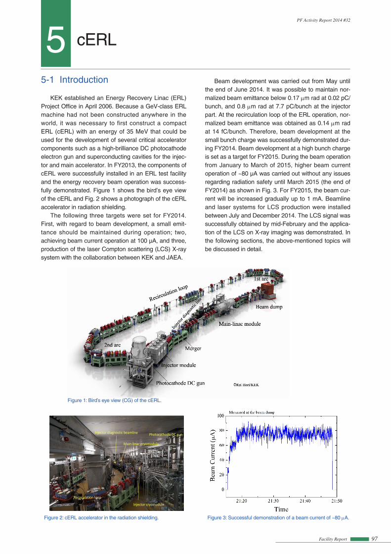
KEK established an Energy Recovery Linac (ERL) Project Office in April 2006. Because a GeV-class ERL machine had not been constructed anywhere in the world, it was necessary to first construct a compact ERL (cERL) with an energy of 35 MeV that could be used for the development of several critical accelerator components such as a high-brilliance DC photocathode electron gun and superconducting cavities for the injec-tor and main accelerator. In FY2013, the components of cERL were successfully installed in an ERL test facility and the energy recovery beam operation was success-fully demonstrated. Figure 1 shows the bird’s eye view of the cERL and Fig. 2 shows a photograph of the cERL accelerator in radiation shielding.
The following three targets were set for FY2014. First, with regard to beam development, a small emit-tance should be maintained during operation; two, achieving beam current operation at 100 µA, and three, production of the laser Compton scattering (LCS) X-ray system with the collaboration between KEK and JAEA.
Figure 1: Bird’s eye view (CG) of the cERL.
Figure 2: cERL accelerator in the radiation shielding.
2
Photocathode DC gun
Injector cryomodule
Main‐linac cryomodule
Recirculation loop
Injector diagnostic beamline
Fig.2
3
Fig.3
Figure 3: Successful demonstration of a beam current of ~80 µA.
Beam development was carried out from May until the end of June 2014. It was possible to maintain nor-malized beam emittance below 0.17 µm rad at 0.02 pC/bunch, and 0.8 µm rad at 7.7 pC/bunch at the injector part. At the recirculation loop of the ERL operation, nor-malized beam emittance was obtained as 0.14 µm rad at 14 fC/bunch. Therefore, beam development at the small bunch charge was successfully demonstrated dur-ing FY2014. Beam development at a high bunch charge is set as a target for FY2015. During the beam operation from January to March of 2015, higher beam current operation of ~80 µA was carried out without any issues regarding radiation safety until March 2015 (the end of FY2014) as shown in Fig. 3. For FY2015, the beam cur-rent will be increased gradually up to 1 mA. Beamline and laser systems for LCS production were installed between July and December 2014. The LCS signal was successfully obtained by mid-February and the applica-tion of the LCS on X-ray imaging was demonstrated. In the following sections, the above-mentioned topics will be discussed in detail.

Facility Report98
PF Activity Report 2014 #32
5-2 Recirculation and Beam Tuning in the cERL
5-2-1 Overview of the operation of the cERLThe principal parameters of the cERL are given in
Table 1. Figure 5 shows the statistics of beam opera-tion time, (the time for which the beam was on) during FY2013–2014 [2]. The first continuous-wave (CW) beams of 20 MeV were successfully transported through the recirculation loop in February 2014 [3, 4]. After the commissioning of operation, various accelerator studies
Design In operation Beam energy 35 MeV 20 MeV Injector energy 5 MeV 2.9-6 MeV Normalized emittance
0.1 µm [email protected] pC 1 µm rad@77 pC
under study
Beam current 10 mA 80 µA
Table 1: The principal parameters of the cERL.
2013 2014 20150
100
200 Installation of LCS system
Commissioning of injector
Current upgarade LCS experiment
Commissioningof recirculation loop
Apr. Apr.
Bea
m O
pera
tion
Tim
e (h
)
Japenese Fiscal YearApr.
Construction ofrecirculation loop
Fig.5
Figure 5: Statistics of beam operation time per month.
Another important milestone of FY2014 was that the “Foundation for High Energy Accelerator Science” presented the “Suwa Award” to the cERL accelerator construction team for the “Construction and beam ac-celeration demonstration of performance by the test accelerator aimed at core technology establishment of energy recovery linac” [1]. Figure 4 shows the picture of the members of the team present at the award cer-emony.
Fig.4
Figure 4: Picture of a part of the cERL construction team members at the “Suwa Award” ceremony in mid-February 2015.
have been carried out. They include the establishment of start-up tuning, correction of beam optics, study on beam losses [5], and measurements of beam emittanc-es in a recirculating loop. In the summer of 2014, the authorities requested a change in the maximum beam current (from 10 µA to 100 µA), and the approval was received in September.
From September to December 2014, an LCS sys-tem was installed. The LCS system aims to demon-strate technology for future high-flux g-ray sources [6, 7] and to develop advanced X-ray imaging technology using compact accelerators [8, 9]. The LCS system consists of an optical cavity resonator, a 1064 nm drive laser, an X-ray beamline, and an experimental hut. The LCS system was operated from February to April 2015. Accelerator issues related to the LCS system are reported in Sec. 2-4. The commissioning results of the LCS system are primarily reported in [7, 9].
5-2-2 Beam DevelopmentA layout of the cERL is shown in Fig. 6. Thirty fluo-
rescent screens are used to measure both the positions and profiles of beams at low average currents. Forty-five stripline beam position monitors (BPMs) are used to measure beam positions non-invasively. Beam currents are measured at the beam dump point and at the gun power supply by subtracting offset currents. They can also be measured using three movable Faraday cups along the beamline.
During machine tuning, low-intensity macropulse beams were produced by the photocathode DC gun with a cathode voltage of 390 kV. The typical param-eters of the beam pulses were as follows: macropulse width of 1.2 ms, macropulse repetition rate of 5 Hz, and bunch frequency of 1.3 GHz.
First, we set up the injector beams. The RF phases in three injector cavities were adjusted to on-crest ac-celeration while a buncher cavity was turned off. The beams were steered at the centers of two solenoids and of the first injector cavity. The total energy of the injec-tor beams was adjusted to 2.9 MeV. Next, we steered beams through a three-dipole merger and main linac (ML) cavities. The RF phases in ML cavities were then adjusted to on-crest acceleration, which yielded total beam energy of 19.9 MeV.
We transported beams through the first arc, the south straight section, and the second arc. The beams were steered at approximately the centers of major quadrupoles while changing the strength of each quad-rupole and monitoring the beam positions downstream. The recirculated beams passed further through an injection chicane where a dipole kick due to a merger dipole is canceled by the other two dipoles. We set the momentum ratio of the recirculated beam to the injected beam to be 7:1. The momentum ratio should be larger than 6:1 because of the finite aperture in the injection chicane.

Facility Report 99
PF Activity Report 2014 #32
Figure 6: Layout of the cERL. The blue and red symbols denote dipole and quadrupole magnets, respectively.
Fig.7
(a) (b)Figure 7: Tuning of decelerating phase. (a) Horizontal beam positions at the dump line as a function of the path length and (b) path length control in the second arc.dipole and quadrupole magnets, respectively.
Fig.8
Figure 8: Demonstration of energy recovery in the ML cavities. Differences in the input and reflected RF powers are shown for the ML cavity 1 (red) and 2(green).
Both injected and recirculated bunches pass through the ML section between the injection chicane and the dump chicane while they are separated longitudinally by approximately half a RF wavelength. We measured the beam positions using four BPMs to ensure non-invasive measurements. The signals were detected at 1.3 GHz, and the signals from the two beams were separated us-ing their timing difference by a beam-recirculation time of 300 ns. We steered beams in this section using cor-rector magnets located upstream the injection chicane because the use of correctors in the main linac section affected both beams. This procedure required delicate tuning of beam recirculation.
The recirculated beams decelerated when they passed through the ML cavities. We adjusted an RF phase of deceleration by changing the path length of the recirculation loop, as shown in an example in Fig. 7. The path length was changed by an orbit bump in the second arc section, shown in Fig. 7(b). The correspond-ing momenta of decelerated beams were measured at a screen in the dump line. The path length was adjusted so that the momenta require a minimum value. The path length can be changed by ±10 mm in each arc, and by ±5 mm in a path-length control chicane. The former method was mainly used because the latter chicane produced some hysteresis in the beam orbit. We found
that an initial path length was very close (within a few mm) to the optimum one.
Figure 8 shows a demonstration of energy recovery in the ML cavities under CW operation. First, we con-ducted a non-ERL operation by reversing an RF phase in the downstream (ML2) cavity. A 2.9-MeV beam was accelerated and decelerated in ML1 and ML2 cavities, respectively, and was transported directly to the dump. Under this operation, both positive and negative beam loadings were observed in the ML1 and ML2 cavities, respectively. However, under the usual ERL operation, we observed little beam loading in these cavities.
Beam emittances were measured using the quad-rupole-scan method. We varied the field strength of a single quadrupole located upstream a screen and measured beam sizes. Measurements at four loca-tions showed that the normalized emittances could be preserved through the ML and the first arc at low bunch charges. For example, horizontal and vertical normal-ized emittances were both 0.14 µm rad just after the first arc at a bunch charge of 14 fC/bunch (macropulse beam). At a medium bunch charge of 0.5 pC, the nor-malized emittances of εnx = 0.41 µm rad (horizontal) and
Figure 2: Layout of the Compact ERL. Blue and red symbols denote dipole and quadrupole magnets, respectively.
εny = 0.3 µm rad (vertical) were obtained after several tunings [10].
Facility Report100
PF Activity Report 2014 #32
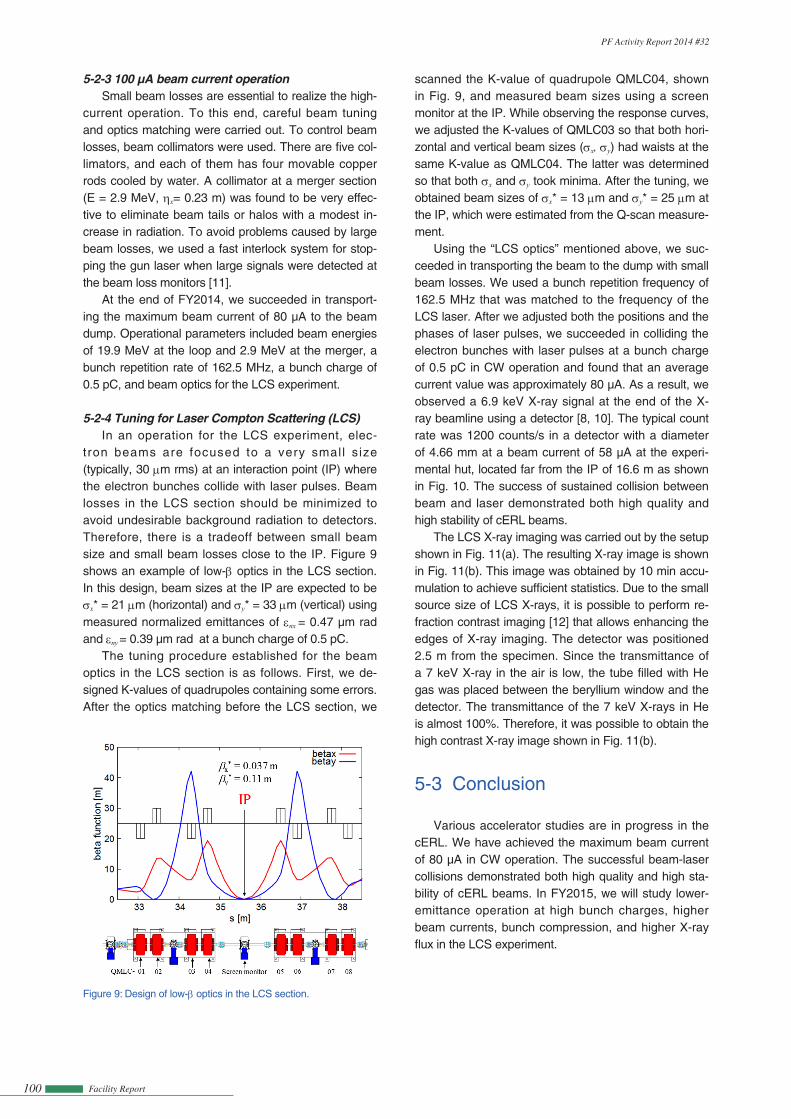
Figure 9: Design of low-β optics in the LCS section.
5-2-3 100 µA beam current operationSmall beam losses are essential to realize the high-
current operation. To this end, careful beam tuning and optics matching were carried out. To control beam losses, beam collimators were used. There are five col-limators, and each of them has four movable copper rods cooled by water. A collimator at a merger section (E = 2.9 MeV, hx= 0.23 m) was found to be very effec-tive to eliminate beam tails or halos with a modest in-crease in radiation. To avoid problems caused by large beam losses, we used a fast interlock system for stop-ping the gun laser when large signals were detected at the beam loss monitors [11].
At the end of FY2014, we succeeded in transport-ing the maximum beam current of 80 µA to the beam dump. Operational parameters included beam energies of 19.9 MeV at the loop and 2.9 MeV at the merger, a bunch repetition rate of 162.5 MHz, a bunch charge of 0.5 pC, and beam optics for the LCS experiment.
5-2-4 Tuning for Laser Compton Scattering (LCS)In an operation for the LCS experiment, elec-
tron beams are focused to a very smal l s ize (typically, 30 µm rms) at an interaction point (IP) where the electron bunches collide with laser pulses. Beam losses in the LCS section should be minimized to avoid undesirable background radiation to detectors. Therefore, there is a tradeoff between small beam size and small beam losses close to the IP. Figure 9 shows an example of low-β optics in the LCS section. In this design, beam sizes at the IP are expected to be
scanned the K-value of quadrupole QMLC04, shown in Fig. 9, and measured beam sizes using a screen monitor at the IP. While observing the response curves, we adjusted the K-values of QMLC03 so that both hori-zontal and vertical beam sizes (sx, sy) had waists at the same K-value as QMLC04. The latter was determined so that both sx and sy took minima. After the tuning, we obtained beam sizes of sx* = 13 µm and sy* = 25 µm at the IP, which were estimated from the Q-scan measure-ment.
Using the “LCS optics” mentioned above, we suc-ceeded in transporting the beam to the dump with small beam losses. We used a bunch repetition frequency of 162.5 MHz that was matched to the frequency of the LCS laser. After we adjusted both the positions and the phases of laser pulses, we succeeded in colliding the electron bunches with laser pulses at a bunch charge of 0.5 pC in CW operation and found that an average current value was approximately 80 µA. As a result, we observed a 6.9 keV X-ray signal at the end of the X-ray beamline using a detector [8, 10]. The typical count rate was 1200 counts/s in a detector with a diameter of 4.66 mm at a beam current of 58 µA at the experi-mental hut, located far from the IP of 16.6 m as shown in Fig. 10. The success of sustained collision between beam and laser demonstrated both high quality and high stability of cERL beams.
The LCS X-ray imaging was carried out by the setup shown in Fig. 11(a). The resulting X-ray image is shown in Fig. 11(b). This image was obtained by 10 min accu-mulation to achieve sufficient statistics. Due to the small source size of LCS X-rays, it is possible to perform re-fraction contrast imaging [12] that allows enhancing the edges of X-ray imaging. The detector was positioned 2.5 m from the specimen. Since the transmittance of a 7 keV X-ray in the air is low, the tube filled with He gas was placed between the beryllium window and the detector. The transmittance of the 7 keV X-rays in He is almost 100%. Therefore, it was possible to obtain the high contrast X-ray image shown in Fig. 11(b).
5-3 Conclusion
Various accelerator studies are in progress in the cERL. We have achieved the maximum beam current of 80 µA in CW operation. The successful beam-laser collisions demonstrated both high quality and high sta-bility of cERL beams. In FY2015, we will study lower-emittance operation at high bunch charges, higher beam currents, bunch compression, and higher X-ray flux in the LCS experiment.
Fig.9
sx* = 21 µm (horizontal) and sy* = 33 µm (vertical) using measured normalized emittances of εnx = 0.47 µm rad and εny = 0.39 µm rad at a bunch charge of 0.5 pC.
The tuning procedure established for the beam optics in the LCS section is as follows. First, we de-signed K-values of quadrupoles containing some errors. After the optics matching before the LCS section, we

Facility Report 101
PF Activity Report 2014 #32
Figure 10: Schematic view of the layout of the LCS beamline.
Figure 11: (a) Schematic layout of the LCS X-ray imaging experimental setup and (b) the LCS X-ray hornet imaging.
[7] R. Nagai, et al., Proc. of IPAC’15, TUPJE002 (2015).[8] T. Akagi, et al., Proc. of IPAC’14, 2072 (2014).[9] A. Kosuge, et al., Proc. of IPAC’15 ,TUPWA066 (2015).[10] T. Miyajima, et al., Proc. of IPAC’15, TUPWA067 (2015).[11] R. Takai, et al., Proc. of IBIC 2014, MOCYB2 (2014).[12] S. W. Wilkins, T. E. Gureyev, D. Gao, A. Pogany, and A. W.
Stevenson, Nature 384, 335 (1996).
Fig.10
Fig.11
REFERENCES[1] http://www.heas.jp/award/h26zyusyou.html
(10 March, 2015, in Japanese)[2] S. Sakanaka, et al. , Proc. of IPAC’15, TUBC1(2015).[3] N. Nakamura, et al., Proc. of IPAC’14, 353 (2014).[4] S. Sakanaka, et al., Proc. of LINAC’14, 599 (2014).[5] O. Tanaka, et al., Proc. of IPAC’15 ,TUPWA068 (2015).[6] R. Nagai, et al., Proc. of IPAC’14, 1940 (2014).