cfd technology development at nasa ames - a mission
TRANSCRIPT

Bulletin of the JSME
Mechanical Engineering ReviewsVol.3, No.1, 2016
0123456789
J-STAGE Advance Publication date: 26 November, 2015Paper No.15-00429
[DOI: 10.1299/mer.15-00429]
1. Introduction
Historically, research in computational fluid dynamics (CFD) can be traced back to the early 1900s. Together with advances in computing hardware and increased demand for computations supporting aerospace vehicle development, CFD technology has developed rapidly, especially since 1970. In this review we focus on CFD pioneered by those at Ames in support of NASA missions in aeronautics and space exploration. The authors’ participation in CFD development and applications goes back to late 1970s and this experience gives us some technical basis to chronologically review how CFD technology at Ames has evolved and impacts on NASA tasks over three decades.
The early development of CFD at Ames was motivated by flow simulation challenges encountered in aeronautics. Realistic applications of CFD to aircraft development were in progress along with the fundamental advances in CFD methods. Most notably, CFD approach has been very successfully used in commercial airplane design (see Johnson et al., 2005). In the space exploration area, however, applications of CFD have been behind aeronautics partially because space-related flow problems involve largely time-dependent and complex flow phenomena requiring advanced flow solvers and physical modeling (for example, see Kiris et al., 2010, 2011). Advanced CFD technology for space transportation vehicle development matured through experiences in realistic applications. Therefore, so-called “best practices” protocols have been developed in conjunction with new vehicle development tasks. In this report, selected examples of flow computations applied to new vehicle development are given with some discussions on requisite capabilities for future applications.
It is to be noted that successful applications of computational technology require the synergy of computing facility, software, simulation tools, data analysis tools, and networks, coupled with the combined knowledge of engineering, flow physics, and computer science. With the compute power provided by NASA Advanced Supercomputing (NAS) facility, Ames has had a rich history of CFD development and applications. In this review we will focus on the CFD development and, for the history of high-end computing facility, readers are referred to Biswas et al. (2012).
We will begin our discussion with a summary of CFD technology developed at Ames in Section 2 that includes major CFD algorithm and grid generation advances, summary of code development and physical modeling advances made at Ames. Application milestones are illustrated via examples derived from supporting aeronautics and space
Abstract To accomplish NASA missions, it is required to develop advanced aerospace vehicles and operating systems. Since a test-fail-fix approach is very expensive and time consuming for developing advanced vehicles, it has become more economical to utilize computational approaches. Scientists and engineers at NASA Ames Research Center (Ames) began developing computational flow modeling methods for aerodynamic problems as early as the late 1960s. As the high-performance computing technologies advance in conjunction with the NASA Advanced Supercomputing (NAS) facility located at Ames, researchers have made breakthroughs in numerical methods and have performed milestone-setting applications while supporting NASA missions. The current report is intended to present our view on the historical role Ames has played in advancing the computational fluid dynamics (CFD) technology starting from the development of fundamental algorithms and codes for aeronautics leading to the current state-of-the-art flow simulations in support of NASA’s aerospace missions.
Key words : CFD, Numerical algorithm, Grid generation, Complex geometry, Flow solver code, Aerospace vehicle development
1
CFD technology development at NASA Ames - A mission computing perspective
Dochan KWAK* and Cetin KIRIS*
*NASA Ames Research Center Moffett Field, CA 94035
E-mail: [email protected]
Received 3 August 2015

2
Kwak and Kiris, Mechanical Engineering Reviews, Vol.3, No.1 (2016)
[DOI: 10.1299/mer.15-00429]
missions. Some features are cross-cutting in nature for both exploration and aeronautics. The examples selected are based primarily on our experiences at Ames for over the past three-plus decades. These examples are selected in approximate chronological order along with advances in computer hardware installed at NAS facility. In Section 3, CFD tools currently in use are recapitulated. In Section 4, current capabilities are illustrated using recent examples. Then a summary of our final thoughts are presented in Section 5. 2. Chronological review of CFD technology developed at Ames
In this Section, we will take a look back at advances made at Ames to meet the mission computing requirements, from advances in algorithms, flow solver codes and turbulence modeling to the development of graphics and post processing tools. The flow simulation procedures were developed by researchers while performing their tasks. Thus desirable attributes for the CFD tools were enforced such as the ease of use, computing efficiency and simplifications in formulation. This fostered an environment to create a suite of useful tools. 2.1 Grid generation advances
Early development of grid generation methods at Ames was primarily based on structured grid using an elliptic grid methods including elliptic, hyperbolic, and Cartesian grid approaches. Then to map complex configurations and bodies of relative motion, an overset grid concept was introduced resulting in the development of sophisticated overset grid-generation tools coupled to flow solvers. Some important history of grid generation development is summarized below: Elliptic grid:
Grid generation research at Ames was started in 1977 (Steger and Sorenson, 1979) for generating 2-D grids for airfoils by solving elliptic partial differential equations following Thompson’s approach (Thompson et al., 1974). A two-dimensional elliptic grid generation code, 2D GRAPE (GRids about Airfoils using Poisson’s Equation), was then developed by Sorenson (1980) followed by the extension to three-dimensional code, 3DGRAPE (1989). Hyperbolic grid:
Elliptic grid generation was followed by a hyperbolic grid generation technique, especially suitable for external aerodynamics (Steger and Chaussee, 1980; Chan and Steger, 1992). Chan et al. (1993) then developed a hyerbolic grid generation code, HYPGEN. Cartesian grid:
The simplest way of discretizing a given flow field would be a uniform Cartesian grid. This can be combined with a simple-refinement and adaptation (Berger et al., 1984). This approach was utilized in an Euler solver, TIGER, by Melton et al. (1991, 1993). A Cartesian grid generator was developed by Aftosmis et al. (1998) and its capability was demonstrated for a variety of configurations. For example, INTERSECT was written for the intersection of triangulated surface meshes to allow for movement of aircraft components further extending mesh generation of extremely complicated geometries. This grid generation routine later became a part of a very versatile Euler code named Cart3D. Overset grid:
With the need for extending body-fitted grid to complex configurations and multi-component geometries and to handle bodies in relative motion, the overset grid generation idea was initiated by Steger et al. (1983). The overset method has been advanced continuously since then and several operational tools have been developed, such as Chimera Grid Tools by Chan et al. (2003) and PEGASUS5 by Suhs et al. (2002). These software tools have been widely used in many flow solvers developed at Ames. Many applications of the overset grid method on complex geometries are shown in Section 2.6 of this paper. Unstructured and other grid generation research:
There are others who performed significant research on grid generation and associated flow solution methods. Most notably, Barth (see, for example, VKI lecture note, 1990) performed seminal research on unstructured grid generation method and associated flow solvers.
Numerous other research codes on grid generation were developed and used to perform various mission computing tasks. For example, Papadopoulos et al. (1999) summarized grid generation routines used for hypersonic vehicles, and a
2

2
Kwak and Kiris, Mechanical Engineering Reviews, Vol.3, No.1 (2016)
[DOI: 10.1299/mer.15-00429]
self-adaptive grid code, SAGE code, was developed by Davies and Vekatapathy (1991, 1995) using the method by Nakahashi and Deiwert (1987). 2.2 CFD algorithm advances
The ultimate goal of CFD was to solve the Navier-Stokes equations in and around aerospace vehicles within a reasonable turn around time. Due to limited capability in computer hardware, various approximate methods were developed first followed by viscous flow algorithms and solvers as the computer speed increases. We will list selected algorithm developed by Ames researchers which made significant impacts on CFD advances in aerospace applications. MacCormack algorithm
In his landmark paper, MacCormack (1969) presented an explicit, predictor-corrector algorithm for solving time-dependent compressible Navier-Stokes equations. This multi-step method is stable and second order accurate in time and space. MacCormack’s explicit scheme has been used for solving many aerodynamic problems for several decades ever since it was first introduced. For example, this scheme was used by Shang and his co-workers (Huband et al., 1989) to produce one of the first Navier-Stokes solutions for an entire aircraft configuration, F-16 in this case. MacCormack made lasting contributions in a series of papers covering shock-boundary layer interaction and hypersonic compression corner problems. His method has been taught in CFD classes and has been used in numerous CFD studies. In 1981, he published an implicit version of his method. Beam-Warming approximate factorization algorithm
It is imperative to have fine grids to capture viscous effects in order to obtain accurate estimate of the performance and stability of aerospace vehicles. The accuracy of the computed results such as the cruise drag, heat transfer and high-lift performance, and practically all internal flow variables are dependent on the accuracy to which viscous effects are computed. Since viscous flow computations require fine grid resolution, implicit methods without severe time-step restriction were in demand.
In 1978, Beam and Warming published a seminal paper entitled “An Implicit Factored Scheme for the Compressible Navier-Stokes Equations.” This paper had an immediate and long-lasting impact on the field of CFD and its impact continues to be strongly felt today. They presented the first practical implicit method for CFD simulations. The main attributes of the method are the implicit nature of the finite-difference equations and the simultaneous use of approximate factorization and the “Delta Form.” The “Delta From” was a new approach to solving the governing equations. It permitted computations of the change in dependent variables (velocities, pressure and density) at each time step. This property has a number of advantages some of which are being used to advantage in designing new algorithms even today. One of these advantages is the ability to drive factorization and linearization errors to zero (these errors are inherent in methods that use approximate factorization and complex flux evaluation that are difficult to linearize).
Beam and Warming’s method reduced the computer time required for a viscous flow computation by one to two orders of magnitude. This had an immediate impact on the field – not in reduced computer time alone, but also in permitting a quantum jump in the scope of problems that could be solved. Two-dimensional viscous flow problems were immediately tractable, and three-dimensional viscous flow computations quickly followed. Beam and Warming’s method then became wide-spread with the introduction of the following generation of computers. Their algorithm paved the way for the routine computations of viscous flow over complex flight vehicles as well as internal flows. The algorithm has been applied to a wide variety of simulations including commercial transport aircraft, advanced military fighters, missiles, air-breathing propulsion systems, and space propulsion systems (space shuttle main engine, for example), to name a few. This algorithm, together with a few other seminal developments in CFD, form the basis for modern day computations of viscous flow.
At Ames, Beam and Warming’s algorithm was incorporated into a series of computer codes: ARC2D/ARC3D, primary viscous flow codes first introduced in 1977 and 1978 (see, Steger 1978, and Pulliam and Steger 1980), followed by many other codes such as Overflow, ROTOR/STAGE and INS3D. These codes, as explained further in the next section, have been used to design, analyze, and improve configurations ranging from full aircraft to propulsion systems, from ventricular assist device to submarines, to name a few. Potential flow algorithms for transonic flow: AF1/AF2
3

2
Kwak and Kiris, Mechanical Engineering Reviews, Vol.3, No.1 (2016)
[DOI: 10.1299/mer.15-00429]
When the flow can be assumed to be irrotational and isentropic, such as the flow at cruise conditions, potential equation formulations can be utilized to achieve one or two orders of magnitude faster solution time than an Euler equation formulation. A number of transonic potential flow algorithms, including approximate factorization algorithms AF1 and AF2, have been developed at Ames during the 1970s. A comprehensive review on Ames activities on potential method development is given by Holst (2009). Diagonal ADI algorithm by Pulliam-Chaussee
To make a coupled block-matrix equation computationally more efficient, a diagonalized implicit scheme was introduced by Pulliam and Chaussee (1981) and applied to Beam and Warming’s approximate factorization scheme. Algorithms for incompressible Navier-Stokes equations
Significant advances in the state-of-the-art in CFD have been made in conjunction with the field of aerodynamics. To be able to use some of the compressible flow algorithms, the artificial compressibility approach of Chorin (1967) was fully extended to three dimensions in generalized coordinates by Kwak et al. (1986). Various solution methods were incorporated into this approach. The Beam-Warming AF algorithm was first implemented followed by an upwinding scheme by Rogers and Kwak (1990) and lower-upper symmetric Gauss-Seidel method by Yoon and Kwak (1991). Traditionally well-known incompressible flow solution method was the pressure-based method by Harlow and Welch (1965) for a 2-D Cartesian grid. This approach was generalized in three-dimensional curvilinear coordinates by Rosenfeld et al. (1991) followed by further improvements by Kiris and Kwak (1996). All these methods were utilized in developing a family of incompressible flow solvers, INS3D. 2.3 Development of flow solvers and codes
Many flow solvers/codes have been developed by individual researchers at Ames that commensurate with computing hardware speed available at the time of development. Later code consolidation efforts combined numerous solvers into more manageable number of codes. The following is a representative list (not a complete list) of solvers developed at Ames, with developers name and reference publications. Small disturbance, potential and boundary layer codes: - Bailey-Ballhaus code: Solves modified small disturbance approximation of the full potential equation (Ballhaus and
Bailey, 1972). - LTRAN2: Solves unsteady, two-dimensional, non-linear, small-disturbance transonic flow equation (Ballhaus and
Goorjian, 1977). - PANAIR: Solves subsonic or supersonic linear potential flow about arbitrary configurations using linear source and
quadratic doublet strength distributions (Carmichael and Erickson, 1981). - TRANAIR: Solves the full potential equation for transonic flow about complex configurations (collaboration between
Boeing and Ames, 1987). - TAIR/TWING: Solves transonic full-potential equation for airfoil/wing analysis (Holst, 1980, see review article by
Holst, 2009). Compressible Euler and Navier-Stokes codes: Euler codes - TIGER: Cartesian grid based Euler solver (Melton et al., 1991, 1993). - Cart3D: Cartesian-based versatile Euler code (Aftosmis, 1998). Received NASA Software of the Year Award in 2002. Navier-Stokes codes: - ARC2D/3D: Euler and thin-layer Navier-Stokes solver (Pulliam/Steger, 1980, and Pulliam, 1984). - TNS: Transonic Euler/Navier-Stokes solver (derived from ARC2D/3D, Holst et al., 1985 and 1987) - Overflow: Navier-Stokes code in general coordinates for multi-block structured overset grids. Evolved from
ARC2D/3D in mid-1980s (discussed more later in this report). - LAVA: Launch Ascent and Vehicle Aerodynamics framework with versatile grid and multi-physics capability (Kiris
et al., 2014)
Incompressible Navier-Stokes codes: - INS3D family of codes: Incompressible Navier-Stokes flow solver (Kwak et al. 1986). For more comprehensive
discussion see Kwak and Kiris (2010). Received NASA Software of the Year Award in 1994.
4

2
Kwak and Kiris, Mechanical Engineering Reviews, Vol.3, No.1 (2016)
[DOI: 10.1299/mer.15-00429]
Aeroelastic codes: - ENSAERO: Fluid/structure interaction code (Guruswamy, 1990). Rotorcraft and turbomachinery codes: - TURNS: Single block Euler/Navier-Stokes code for rotorcraft (Srinivasan and Baeder, 1993). - ROTOR2/3: Rotor-stator interaction code (Rai, 1987). - STAGE2/3: Multi-stage turbomachinery code derived from the rotor-stator interaction code (Gundy-Burlet et al.,
1989). 2.4 Turbulence modeling advances
Ames researchers made significant contributions to modeling turbulence encountered in aerospace engineering, i.e. for obtaining CFD results for developing airplanes and spacecrafts. Some of these models have been extensively used in aerospace applications and many other versions derived from these models have emerged later for general applications. A partial list is given below: - Baldwin-Lomax algebraic model: An algebraic model for engineering applications. Developed by Baldwin and
Lomax (1978), this model is one of the most used turbulence models. - Johnson-King model: An algebraic model for 2-D separated boundary layer with strong adverse pressure gradient
(Johnson-King, 1984). - q−ω model: One of two equation variations by Coakley (1983, 1984). - Shear Stress Transport (SST) model: A two-equation model to account for principal turbulent shear stress in adverse
pressure gradient boundary layer, developed by Menter while working at Ames (1993). - Baldwin-Barth one-equation model: An one-equation model where the length scale expression is derived from k −ε model in lieu of an algebraic length scale prescription (Baldwin and Barth, 1991).
- Large Eddy Simulation (LES) methodology: Many performed research on the development of LES methodology (jointly with Turbulent Flow Computation group at Stanford Mechanical Engineering Department).
2.5 Post processing and scientific visualization tools
As the flow solver technologies advance and computing hardware increases its capacity, the need for post processing the results grew rapidly. To meet this need, Ames researchers made major advances in scientific visualization and developed post-processing tools which became industry standards. Tools include: - PLOT3D: Primarily developed by Buning (Walatka, 1990). The PLOT3D grid and solution file format is one of the
most compact and widely used file exchange formats in the CFD community for the last 30 years. - FAST: Flow Analysis Software Toolkit developed by Bancroft et al. (1990). Received NASA Software of the Year
Award in 1995. - UFAT: Unsteady Flow Analysis Toolkit, a particle tracer for time-dependent flow fields (Lane, 1994).
These tools were disseminated to aerospace industry and computer manufacturers. Some of these were the starting point for developing flow visualization and analysis software commercially available today. 2.6 Selected examples of flow simulation advances
Real-world applications require development of simulation procedures involving geometry modeling and grid generation, designing initial and boundary condition procedures, implementation of flow solvers to best utilize computer architecture and memory, selection of adequate physical models, and post processing the results of huge computer-generated data sets. Even after a flow solver has been developed and validated with fundamental test cases, applications involving complex geometry and/or complex flow physics problems require all these aspects properly implemented. Very often the real-world application is an engineering art.
There are number of Ames-first type problem-solving examples related primarily to NASA missions. During 1980s and early 1990s, Paul Kutler, as the head of Applied Computational Aerodynamics Branch and then as the chief of Fluid
5
2
Kwak and Kiris, Mechanical Engineering Reviews, Vol.3, No.1 (2016)
[DOI: 10.1299/mer.15-00429]
Dynamics Division, archived highlights of CFD solutions obtained by researchers at Ames. During this period, Ames hosted many visiting scholars from other countries: Drs. N. Satofuka, K. Fujii, K. Nakahashi, S. Obayashi, K. Kuwahara, and Y. Nakamura from Japan, W. Kordula from Germany, and M. Rosenfeld from Israel to name a few. Research results have been published in papers by these individuals some of which are cited in this report.
Significant milestone cases are listed below in different time periods where computer speed at NASA Advanced Supercomputing (NAS) facility is indicated. It is interesting to note that many of the early results were produced using the supercomputers speed of which was measured in GFLOPS compared to PFLOS we use now in 2015. Researchers could accomplish major advances in understanding fundamental fluid dynamics phenomena as well as in designing components of aerospace vehicles and other flow devices. These examples are listed in chronological order to illustrate a timeline showing how computer speed and flow simulation capability advanced. Researchers associated with examples selected are identified although these examples represent only a small portion of what has been generated. More complete details of each can be found in the references cited.
Examples are presented next in chronological order with names of compute hardware. The speeds indicate representative peak speeds and do not represent the official NAS facilities timing. The actual speed for computations is usually limited to a fraction of the peak speed. Here, examples are mapped to NAS computer timeline. However, since projects usually span several generations of compute hardware, it is difficult to place illustrations exactly at the point they were first generated. For example, the Space Shuttle Program lasted for 30 years and throughout this operational period numerous milestone-setting solutions were obtained. Therefore, it is attempted to best illustrate the types of CFD simulations researchers could generate as computer capability advanced. 2.6.1 Year 1983~1988 (NAS Program started in 1983)
NAS computers: Cray X-MP (0.21 GFLOPS), Cray 2 (1.95 GFLOPS)
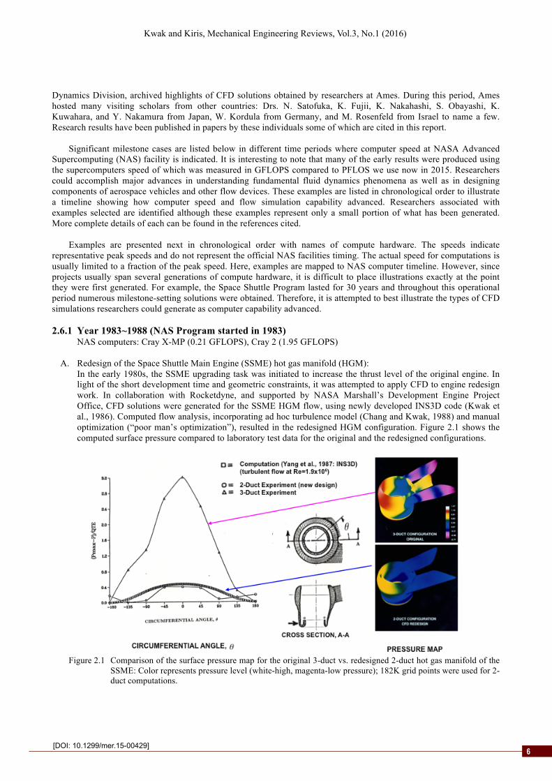
A. Redesign of the Space Shuttle Main Engine (SSME) hot gas manifold (HGM): In the early 1980s, the SSME upgrading task was initiated to increase the thrust level of the original engine. In light of the short development time and geometric constraints, it was attempted to apply CFD to engine redesign work. In collaboration with Rocketdyne, and supported by NASA Marshall’s Development Engine Project Office, CFD solutions were generated for the SSME HGM flow, using newly developed INS3D code (Kwak et al., 1986). Computed flow analysis, incorporating ad hoc turbulence model (Chang and Kwak, 1988) and manual optimization (“poor man’s optimization”), resulted in the redesigned HGM configuration. Figure 2.1 shows the computed surface pressure compared to laboratory test data for the original and the redesigned configurations.
Figure 2.1 Comparison of the surface pressure map for the original 3-duct vs. redesigned 2-duct hot gas manifold of the
SSME: Color represents pressure level (white-high, magenta-low pressure); 182K grid points were used for 2-duct computations.
6

2
Kwak and Kiris, Mechanical Engineering Reviews, Vol.3, No.1 (2016)
[DOI: 10.1299/mer.15-00429]
This first known application of CFD to rocket propulsion systems development led to the replacement of the original three-duct HGM design with the new two-duct design. After cold air and hot fire experiments followed by certification tests, the new two-duct design made its first flight on Shuttle Discovery’s 20th mission (STS-70) (Space Transportation System-70) in July 1995. (see Chang et al., 1988, Yang et al., 1992, and, for a complete detail of the SSME-related CFD work, see Kwak and Kiris, 2010).
B. Three-dimensional vortical and separated flow:
Many cases of complex flow phenomena were studied computationally even though the geometry is fairly simple as illustrated next.
B.1 Flow over a double-delta wing: Interaction between vortex emanating from the leading edge of the strake with that from the leading edge of the wing was computed by Fujii (Fig. 2.2) while residing at Ames as a postdoctoral research fellow working with L. Schiff (Fujii and Schiff, 1989).
Figure 2.2 Computed total pressure contour plots for double-delta configuration: M=0.3, alpha=30 degree,
Re=1.3x10⁶, 853K grid points (Computation by Fujii, Graphics by Buning and Fujii). B.2 Juncture flow:
Juncture flow is encountered in many flow problems such as the flow around wing-fuselage junction, liquid oxygen post in the SSME injector, submarine-appendage junction to name a few. Flow topology is complicated and dependent on Reynolds number. One of the early computations is illustrated in the Fig. 2.3:
(a) Computed particle traces (b) Oil flow visualization
Figure 2.3 Flow around a single post: (a) Computed, Re=1,000, 115K grid points (Kaul et al. 1985), (b) Oil flow visualization at Re=1.85x10⁵ (G. Schewe, DFVLR, 1985).
B.3 Wing-tip vortex flow:
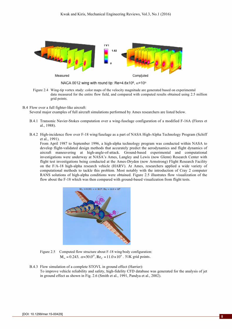
Wing-tip vortex generation and near-wake propagation was studied both experimentally and computationally. As shown in Fig. 2.4 (Dacles-Mariani et al., 1999), computed results were compared with experimental measurements which mapped the entire flow field.
7
2
Kwak and Kiris, Mechanical Engineering Reviews, Vol.3, No.1 (2016)
[DOI: 10.1299/mer.15-00429]
Figure 2.4 Wing-tip vortex study: color maps of the velocity magnitude are generated based on experimental
data measured for the entire flow field, and compared with computed results obtained using 2.5 million grid points.
B.4 Flow over a full fighter-like aircraft:
Several major examples of full aircraft simulations performed by Ames researchers are listed below. B.4.1 Transonic Navier-Stokes computation over a wing-fuselage configuration of a modified F-16A (Flores et
al., 1988). B.4.2 High-incidence flow over F-18 wing/fuselage as a part of NASA High-Alpha Technology Program (Schiff
et al., 1991). From April 1987 to September 1996, a high-alpha technology program was conducted within NASA to develop flight-validated design methods that accurately predict the aerodynamics and flight dynamics of aircraft maneuvering at high-angle-of-attack. Ground-based experimental and computational investigations were underway at NASA’s Ames, Langley and Lewis (now Glenn) Research Center with flight test investigations being conducted at the Ames-Dryden (now Armstrong) Flight Research Facility on the F/A-18 high-alpha research vehicle (HARV). At Ames, researchers applied a wide variety of computational methods to tackle this problem. Most notably with the introduction of Cray 2 computer RANS solutions of high-alpha conditions were obtained. Figure 2.5 illustrates flow visualization of the flow about the F-18 which was then compared with ground-based visualization from flight tests.
Figure 2.5 Computed flow structure about F-18 wing/body configuration:
M∞ = 0.243, α=30.0O, ReC =11.0×10⁶ , 51K grid points.
B.4.3 Flow simulation of a complete STOVL in ground effect (Harrier): To improve vehicle reliability and safety, high-fidelity CFD database was generated for the analysis of jet in ground effect as shown in Fig. 2.6 (Smith et al., 1991, Pandya et al., 2002).
8

2
Kwak and Kiris, Mechanical Engineering Reviews, Vol.3, No.1 (2016)
[DOI: 10.1299/mer.15-00429]
(a) (b)
Figure 2.6 High-fidelity simulation of jet in ground effect (Harrier): (a) snap shot of unsteady flow visualization of 3.8 million grid-points simulation, (b) database generated for virtual flight simulation, where “suck-down” effect means induced low pressure underneath the vehicle due to high-speed jet flows along the ground plane.
B.5 Full simulation of Space Shuttle stack performance (with NASA/JSC and Rockwell International):
Computed results for flow over the Space Shuttle orbiter was first reported by Chaussee et al. (1985). Full simulations of the complete Shuttle stack have been performed by numerous researchers primarily at NASA Ames and NASA Johnson Space Center. First complete stack simulation using overset-grid approach was reported by Buning et al. in 1988.
B.6 Simulation of rotor-stator interaction:
Single and multi-stage turbomachinery performance were simulated (Rai, 1987 and Gundy-Burlet et al., 1989). 2.6.2 Year 1989~2000
NAS computers: Cray Y-MP (2.54 GFLOPS), Cray C-90 (15.36 GFLOPS), IBM SP2 (42.56 GFLPS), SGI Origin 2000 (512 CPUs at 409.6 GFLOPS)
A. Simulation of the turbopump flow in a liquid-propellant rocket engine:
Internal flow encountered in liquid-propellant rocket engines poses modeling challenges different from external aerodynamics. Internal flow CFD applications can be classified into three major categories, namely, complex internal flow, turbopumps (turbine and pump), and flow in combustion devices. Simulations of these flows have been performed individually in the past. Since early 1980s, CFD simulations for propulsion systems have been performed for designing and retrofitting, which eventually led to the formation of Propulsion CFD Consortium in the 1990s at the NASA/Marshall Space Flight Center (MSFC) (McConnaughey and Schutzenhofer, 1992; Garcia et al., 1992). The goal was to advance CFD capability for propulsion systems development. Through this effort, useful approaches and issues relevant to propulsion CFD were discussed among experts in the field.
During this period, for future engine development, high-fidelity unsteady simulation capability was developed for
the rocket engine turbopump. A validation computation is illustrated in Fig. 2.7 which shows reasonable agreement between the computations and the experimental measurements. Issues related to high-speed turbopump simulations and how Ames contributed to resolve some of the issues are discussed by Kiris et al. (1993).
B. Space Shuttle ascent analysis:
Applications of the Overflow code to Space Shuttle Launch Vehicle (SSLV) and Orbiter have led to an overall better understanding of the aerodynamic loads on the Space Shuttle, and has served as the primary tool for verifying wind tunnel measurements. Following the Shuttle flight STS-27R (launched and landed in December 1988), it was observed that damage had incurred during this flight. Subsequently, debris analysis led to the determination that insulation and ice from the external tank striking the orbiter were the cause of damage. Since then the CFD analysis has had a major positive impact on the Shuttle Program, increasing the flight safety by identifying and minimizing hazardous debris
9

2
Kwak and Kiris, Mechanical Engineering Reviews, Vol.3, No.1 (2016)
[DOI: 10.1299/mer.15-00429]
sources. Figure 2.8 illustrates CFD analysis of debris from the booster of the Space Shuttle Launch Vehicle by S. Rogers.
Figure 2.7 Validation of turbopump computational procedure using SSME HPTFTP 11” impeller Shrouded impeller:
6 full blades, 6 long partial, 12 short partial 6322 rpm, Re=1.81x10⁵ per inch, 34 million grid points.
(a) (b)
Figure 2.8 Space Shuttle Launch Vehicle flow field in ascent: (a) M=1.25, vehicle surface colored by pressure, and flow field colored by local Mach number; (b) Debris trajectory analysis during flight STS-27R (source: S. Rogers). Typical simulations require 24 million grid points or more.
C. 6-DOF simulation of Shuttle SRB separation:
The original idea by Steger et al. (1983) of using overset grid for moving body simulation was extended to key technological advances that facilitate computational unsteady aerodynamic forensics. Soon after the Space Shuttle Challenger accident on January 28, 1986, Meakin and Suhs (1989) performed 6-DOF simulation of SRB separation from the Shuttle orbiter in December 1988 (Fig. 2.9). For this simulation, simplified geometries were used. Later simulations included more complete geometric details such as protuberances and ramps of the SSLV (e.g. Gomez et al., 2004).
D. Simulation of a high-lift transport aircraft:
In order to develop aerodynamic analysis capability of an aircraft during landing with flaps/slats deployed, multi-element airfoil computations were performed first (see summary by Rogers, 1994). Viscous flow computation procedures for a full landing configuration of a transport aircraft were developed by the NASA Advance Subsonic Technology (AST) program (Rogers et al., 2001).
10

2
Kwak and Kiris, Mechanical Engineering Reviews, Vol.3, No.1 (2016)
[DOI: 10.1299/mer.15-00429]
(a) (b)
Figure 2.9 Unsteady aerodynamics involving Shuttle SRB separation: (a) Space Shuttle Challenger accident, (b) CFD simulation using 350K grid points by Meakin and Suhs (1989); Cp contours, M=4.5, alpha=2o, Re=6.95x10⁶
Figure 2.10 illustrates an example of successful development of Navier-Stokes solution procedures. In Fig. 2.10, an overset grid arrangement is shown for Boeing 777-200 aircraft configured for landing.
(a) (b) Figure 2.10 Overset grid system for a complete Boeing 777-200 landing configuration: (a) surface grid,
(b) details of inboard flap-bracket fairing. Overset methods enabled detailed studies of the viscous flowfield with high-lift devices deployed, and procedures for obtaining accurate solutions of the Navier-Stokes equations in wake flow with near the onset of blunday layer separation. The computations were performed with 22.4 million grid points with 79 zones, which took 200 CPU hours on the C90. The computed results were compared with experimental data acquired at the NASA Ames 12-Foot Pressure Wind Tunnel. At approach conditions, computed lift was within 1.5% of experimental data and within 4% for drag. Full detail can be found in Rogers et al. (2001).
2.6.3 Year 2001~2003
NAS computers: SGI Origin 3800 (1,024 CPUs at 1.23 TFLOPS)
A. Analysis and redesign of axial flow blood pump (NASA-DeBakey VAD): The CFD code, INS3D, was utilized in designing the NASA-DeBakey ventricular assist device (VAD), which resulted in the development of the final design configuration that enabled human implantations (Kiris et al., 1998). Features of INS3D enhanced for simulating hemodynamic problems can be found in Kim et al. (2006) and Kwak and Kiris (2015). The new VAD has been successfully implanted in more than 450 patients to date (Received NASA Commercial Invention of the Year Award in 2002). In Fig. 2.11, a schematic of human implantation is shown. Baseline and final design configurations are compared. As shown in the table, the final design reduces the red cell damage (hemolysis index) by 90% and the blood clots (hemolysis index) did not form
11

2
Kwak and Kiris, Mechanical Engineering Reviews, Vol.3, No.1 (2016)
[DOI: 10.1299/mer.15-00429]
enabling continuous pump operations. The resulting performance improvements thus enabled human implantation.
Figure 2.11 CFD improved axial flow blood pump which enabled human implantation. Computations were performed using 350K or more grid points.
2.6.4 Year 2003~2009
NAS computers: SGI Altix 3000 (512 CPUs at 2.66 TFLOPS), SGI Altix 3700 (10,240 processor Columbia at 63 TFLOPS) + Altix 3700/4700 (13,824 CPUs at 85.8 TFLOPS).
A. STS-107 accident investigation support: The flow simulation capability for complex configurations steadily increased, and the capability was fully demonstrated in supporting STS-107 (Columbia) accident investigation. Figure 2.12 and 2.13 illustrate how CFD simulation has been utilized during the accident investigation. Full detail of the computational support can be found in Gomez et al. (2004).
Cp contours on surface and y=0 plane
(a) (b)
Figure 2.12 Overset grid arrangement and computed results: (a) surface grid for Shuttle orbiter, solid rocket booster and external tank, (b) Cp contours on surface and symmetry plane at Mach=2.46, Alpha=2.08, Overflow solution of STS-107 using 34 million grid points.
As a part of Columbia accident investigation, CFD analysis was combined with 6-DOF simulations with Cart3D Euler solver to identify large pieces of foam impacting orbiter wing by Aftosmis (Fig. 2.13). Shown in this figure are multiple-exposure of a moving-body simulation of debris event at M=2.46, alpha=2.08o.
B. Shuttle return to flight (RTF) support: B.1 Debris transport analysis:
Following STS-107, debris transport software was developed by S. Rogers for the Return-To-Flight (RTF) risk assessment. The debris-drag models using Cart3D 6-DOF unsteady simulations were developed and a wide
12

2
Kwak and Kiris, Mechanical Engineering Reviews, Vol.3, No.1 (2016)
[DOI: 10.1299/mer.15-00429]
variety of potential impact scenarios were computed by Rogers (Fig. 2.14). The details of these computations were reported in conjunction with STS-107 investigation by Gomez et al. (2004) and Murman et al., (2005).
(a) (b)
Figure 2.13 Unsteady Cart3D simulation using 4 million grid points showing the trajectory of a piece of tumbling foam debris released during ascent: multiple exposure of (a) a single foam, (b) a foam shedding from the bipod ramp region impacts carbon-carbon panels on the orbiter wing.
Figure 2.14 Debris transport analysis options (figure provided by S. Rogers).
B.2 Flowliner crack analysis and determination of flight rationale: Liquid hydrogen is transported from the external tank to the shuttle main engines through the feedline. This feedline has bellows such that it can flex during the launch (Fig 2.15). To maintain the smooth flow in the feedline, a device called flowliner is used. It was observed during the Shuttle RTF inspection that cracks were developed in the Shuttle flowliner, and it was necessary to determine the root cause of the crack before RTF. Therefore, unsteady flow analysis of the liquid hydrogen pump for the flowliner was performed using INS3D (Kiris et al., 2008). For return to flight support, flight rationale had to be determined once engineering fixes have been implemented. Figure 2.15 shows a snapshot of the computed velocity magnitude and a comparison of computed and measured pressure oscillations near the crack. CFD was utilized throughout the RTF support period.
C. IOP in Flame Trench: During the initial buildup of thrust when a rocket engine is ignited, large magnitude ignition overpressure (IOP) and duct overpressure waves are generated. The IOP waves from the nozzle exit create large oscillatory pressures beneath the mobile launch pad. The strong compression waves, along with their reflections in the flame trench, travel back to the launch vehicle and through the exhaust holes of the rocket engine potentially having damaging effects on the vehicle, its payloads (including avionics) and any surrounding structures. The launch pad and the
13
2
Kwak and Kiris, Mechanical Engineering Reviews, Vol.3, No.1 (2016)
[DOI: 10.1299/mer.15-00429]
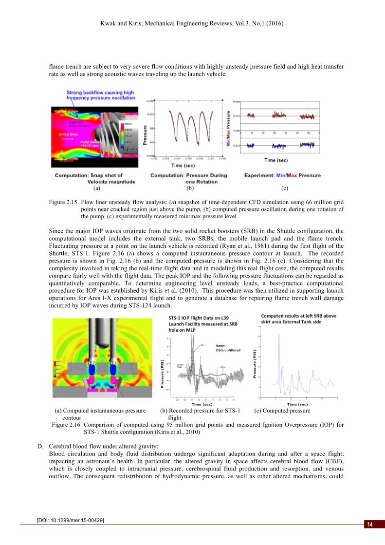
flame trench are subject to very severe flow conditions with highly unsteady pressure field and high heat transfer rate as well as strong acoustic waves traveling up the launch vehicle.
(a) (b) (c)
Figure 2.15 Flow liner unsteady flow analysis: (a) snapshot of time-dependent CFD simulation using 66 million grid points near cracked region just above the pump, (b) computed pressure oscillation during one rotation of the pump, (c) experimentally measured min/max pressure level.
Since the major IOP waves originate from the two solid rocket boosters (SRB) in the Shuttle configuration, the computational model includes the external tank, two SRBs, the mobile launch pad and the flame trench. Fluctuating pressure at a point on the launch vehicle is recorded (Ryan et al., 1981) during the first flight of the Shuttle, STS-1. Figure 2.16 (a) shows a computed instantaneous pressure contour at launch. The recorded pressure is shown in Fig. 2.16 (b) and the computed pressure is shown in Fig. 2.16 (c). Considering that the complexity involved in taking the real-time flight data and in modeling this real flight case, the computed results compare fairly well with the flight data. The peak IOP and the following pressure fluctuations can be regarded as quantitatively comparable. To determine engineering level unsteady loads, a best-practice computational procedure for IOP was established by Kiris et al. (2010). This procedure was then utilized in supporting launch operations for Ares I-X experimental flight and to generate a database for repairing flame trench wall damage incurred by IOP waves during STS-124 launch.
(a) Computed instantaneous pressure (b) Recorded pressure for STS-1 (c) Computed pressure
contour flight Figure 2.16 Comparison of computed using 95 million grid points and measured Ignition Overpressure (IOP) for
STS-1 Shuttle configuration (Kiris et al., 2010)
D. Cerebral blood flow under altered gravity: Blood circulation and body fluid distribution undergo significant adaptation during and after a space flight, impacting an astronaut’s health. In particular, the altered gravity in space affects cerebral blood flow (CBF), which is closely coupled to intracranial pressure, cerebrospinal fluid production and resorption, and venous outflow. The consequent redistribution of hydrodynamic pressure, as well as other altered mechanisms, could
14

2
Kwak and Kiris, Mechanical Engineering Reviews, Vol.3, No.1 (2016)
[DOI: 10.1299/mer.15-00429]
compromise regulatory processes in different parts of the brain. To assess the impact of changing gravitational forces on an astronaut’s biomedical function, the ability to predict CBF as an element of a cephalad fluid shift model is of major importance. This capability will enable the investigation of fluid shifts on brain function—especially on vision— under different scenarios encountered by astronauts during long-duration space missions and after arriving at their destination.
Figure 2.17 Instantaneous velocity magnitude through Cerebral Arterial Circle using clinical geometry and
representative human pulse. Simulations were performed using 2 million grid points. As a step toward developing a CBF model, Kim et al. (2006) developed a procedure to model blood flow through the Cerebral Arterial Circle (commonly known as Circle of Willis, CoW). Figure 2.17 shows an instantaneous flow field using a clinical geometry of CoW and average human pulse (amplitude and frequency). Geometry extraction and physiological modeling procedures are essential for extending CFD to brain hemodynamics. Further details of CBF modeling and other computational aspects can be found in Kwak and Kiris (2015).
2.6.5 Year 2010~2015
NAS computers: Pleiades-primary production system with SGI ICE, 84,952 cores (1.10 PFLOPS), SGI ICE X cluster, 210,336 cores (Intel Xeon six-, eight-, and twelve core processors), 5.35 PFLOPS peak speed
Examples of CFD applications utilizing the current computing facility (in 2015) are given in Section 4.
3. Summary of current CFD tools at Ames
In Section 2 above, Ames contributions to the development of fundamental CFD algorithms and applications procedures have been reviewed. Several review articles have been published in the past about Ames contributions to specific topical areas. To name a few, Pulliam et al. (1999) gave a detail review on Ames contributions to fundamental CFD in conjunction with Havard Lomax’s legacy to Ames CFD; Holst (2009) on transonic flow potential method; Chan (2009) on overset grid technology; Pulliam on implicit methods (2009); Kwak and Kiris (2009) on incompressible flow methods. In this section, CFD tools currently being used at Ames in mission computing are recapitulated, followed by examples using these tools in the next section. 3.1 Overset grid technology
To model complex multi-component configurations, the overset grid technology was developed and associated tools have been applied to CFD problems at NASA. One of the early motivations was to simulate the flow involving multiple bodies in relative motion (Meakin and Suhs, 1989), where body-fitted grid can be used for each component especially suitable for solving viscous flow problems.
Starting from the inception of the concept in the 1970s, much of the development was done in the 1980s and continued in the 1990s. In light of the continued usage, a versatile and all-inclusive software package Chimera Grid Tool (CGT) was developed by Chan et al. (2005, 2006). An example of overset grid is shown in Fig. 2.12 where the overset grid arrangement is shown for computing flow over Space Shuttle orbiter with external tanks. Many complex geometryexamples shown in Section 2.6 utilized overset grid. The overset grid tools are being used in a wide variety of
15
2
Kwak and Kiris, Mechanical Engineering Reviews, Vol.3, No.1 (2016)
[DOI: 10.1299/mer.15-00429]
complex configuration applications. A comprehensive review on overset grid technology development can be found in the recent review by Chan (2009). 3.2 Cart3D
One of the major goals of CFD was to solve viscous flow around complex configuration. The body-fitted curvilinear grid was the most popular choice for accomplishing this. However, the drawback is that the grid generation requires large human time and effort. Since many features of aerodynamic performance can be predicted using an inviscid Euler formulation, the Cartesian-based grid generation approach combined with an Euler solver became very attractive for computing economy. An early version of the Cartesian-based flow simulation tool was developed by Melton et al. (1991, 1993). This is followed by the development of a highly automated grid generation and flow solution software, Cart3D (Aftosmis et al., 1998).
Cart3D has been widely used in aerospace engineering as well as other industrial flow analysis tasks. At NASA, Cart3D has been used for static and dynamic data base generation for launch vehicle development, trajectory analysis, accident investigation and return to flight retrofitting during the Shuttle program. The capability will be further illustrated later in the next section. 3.3 Overflow
In the 1980s one of the major CFD challenges was to obtain viscous flow solutions for complex configurations. To meet this need, Ames researchers developed a Navier-Stokes solver in general curvilinear coordinates combined with the overset grid approach.
In 1978, Steger (1978) extended Beam-Warming’s Approximate Factorization algorithm to general coordinates in 2D. Pulliam and Steger (1980) extended this to three dimensions followed by the development of Pulliam and Chaussee’s diagonal algorithm (1981). Steger made far-reaching influence on code development and applications procedure at Ames. For example, his coding style dominated Ames-developed codes. A comprehensive review, including Steger’s contributions on Ames implicit algorithm development is given by Pulliam (2009).
In 1984, Pulliam created ARC2D and ARC3D. This code evolved into Overflow starting around mid-1980s. Various algorithms were incorporated into the code such as Steger’s two-factored flux-split F3D scheme (1986) and others. However, in the current working version, Beam-Warming’s AF scheme constitutes the kernel of Overflow. Buning has been the focal point in maintaining and updating the code with latest algorithmic and coding advances (see Overflow manual by Buning et al., 2002, and updates for subsequent versions).
Overflow has been used in practically all NASA projects requiring subsonic and supersonic flow analysis and has been disseminated practically to all other NASA centers and US aerospace industry as well. Application examples will be given later in this report. 3.4 LAVA
As the CFD tools advance, it became desirable to be able to choose different algorithm and grid topology, and to include additional physics such as heat transfer and aero-acoustics. This versatile capability is in need especially to support launch vehicle design, testing and operations. The Launch Ascent and Vehicle Aerodynamics (LAVA) framework is developed (Kiris et al., 2014) to provide versatility in grid/geometry modeling, fast turn around, and multi-physics capability. The LAVA framework essentially includes modules that can handle CFD, Conjugate Heat Transfer (CHT) and Computational Aero-Acoustics (CAA), and extended capabilities are being added.
Various solution methods and gridding approaches have been utilized in many NASA Ames developed legacy codes such as INS3D (Kwak et al., 1986), Overflow (Buning et al., 2002), DPLR (Wright et al., 2009), and Cart3D (Aftosmis et al., 1998). These codes were originated to accomplish specific tasks and have made significant impacts on several major NASA missions. However, for general applications, there does not exist the best method. The decision on which method to choose is largely problem dependent. Even for solving one configuration, the best approach may vary at sub-problem level to accomplish efficiency and accuracy of the solution procedure. The LAVA framework is still in a continuous development phase and is designed to be grid-flexible. For example, this framework can handle Cartesian,
16

2
Kwak and Kiris, Mechanical Engineering Reviews, Vol.3, No.1 (2016)
[DOI: 10.1299/mer.15-00429]
block-structured or unstructured grid either in stand-alone mode or by coupling different grid types through an overset interface. 4. Highlights of current practices
As reviewed in the previous sections, the need for supporting high-priority NASA projects has led to the development of a suit of CFD procedures for solving mission-support problems. These problems involve complex configurations and operating conditions not typically addressed by academia, and usually require in-depth understanding of the flow physics involved. The pervasive use of experiments and flight tests for code validation increase the credibility of solutions, however, this does not guarantee the same level of solution quality when extended to other configurations and flow conditions. Very often best practice guidelines are established for generating a database for a wide range of operating conditions for a task on hand. Current practices of CFD applications are highlighted in this section via examples selected from simulations associated with current or recent tasks. These examples represent the state-of-the-art in CFD applications utilizing Ames-developed tools and NAS computing facility. 4.1 Cart3D: Virtual flight database to support flight test
Figure 4.1 shows snapshots from the aerodynamic database supporting development of the MCEV-Orion Launch Abort Vehicle and the pad abort test, "PA-1" flight-test. The test was conducted at the White Sands Missile Range on May 6, 2010. The vehicle was developed using aerodynamic database results obtained with Cart3D and Overflow codes on supercomputers at the NAS Advanced Supercomputing facility. Inset snapshots show just of a few of the 15,000+ simulations performed using Cart3D to study the vehicle's aerodynamics and to develop the flight control system (Aftosmis, 2008, and Aftosmis et al., 2009).
Figure 4.1 Snapshots from the aero-database used for the Pad-Abort test of Orion ("PA-1 flight test").
17

2
Kwak and Kiris, Mechanical Engineering Reviews, Vol.3, No.1 (2016)
[DOI: 10.1299/mer.15-00429]
4.2 Overflow: Aerodynamics of ascending vehicle
With the retirement of the shuttle program, NASA is developing a new heavy-lift capability, the Space Launch System (SLS). Other vehicles such as SpaceX’s Falcon, Delta IV and Atlas could be other candidate vehicles in service in the future. To develop heavy-lift launch vehicles for NASA’s future space exploration missions, aerodynamic data throughout the entire ascent trajectory are heavily utilized during design iterations. Generation of aerodynamic database encompasses prediction of integrated and distributed loads for a wide range of Mach numbers from subsonic to high supersonic, as well as pitch and yaw angles in the range of 10 degrees. A multi-stage process is utilized to efficiently generate the large aerodynamic database with evolving geometric configurations.
The SLS program is tasked with developing a new series of launch vehicles, and although many components include legacy hardware from the Space Shuttle program, this requires developing many aerodynamic related databases. Budget limitations constrain the number of wind-tunnel tests, thus the program relies on CFD analysis to provide a significant amount of data. Use of CFD enables a reduction in conservatism that can be translated into higher payload to orbit.
The computed result shown in Fig. 4.2 shows an example how CFD tools, in this case Overflow code, are being utilized in preparation for building a booster-separation aerodynamic database. The Overflow code is especially suitable for this type analysis requiring complex geometry modeling capability involving bodies of relative motion. The large number of basis variables will require tens of thousands of simulations. The accuracy of the simulations will be assessed by comparison to newly acquired wind-tunnel data, with the goal of reducing the aerodynamic uncertainty within the database.
Figure 4.2 Snapshot of the computed flow field of a Space Launch System in ascent: Overflow solution showing instantaneous Mach contour and surface pressure map.
18

2
Kwak and Kiris, Mechanical Engineering Reviews, Vol.3, No.1 (2016)
[DOI: 10.1299/mer.15-00429]
4.3 LAVA: Flow analysis along ascent trajectory
The best practices for generating aero-database for Ares V in ascent were established by Kiris et al. (2011) in order to support vehicle design. Current CFD codes performed reasonably well for characterizing fore-body aerodynamics without the plume effects. This procedure shows an example of the current CFD capability for generating a series of vehicle aerodynamics data when the flow is primarily attached and the plumes are not included in the model.
The database generation is based on a series of steady-state conditions along the trajectory. Since the flow does not involve massive separation, the current practices and lessons learned from the sensitivity evaluation are valuable for vehicle development. Here, the aerodynamic data at different points along the trajectory are represented by steady-state solutions using the external flow conditions at trajectory locations. Whether these solutions truly represent snapshots of the unsteady flow while the vehicle is in motion needs to be validated in the future.
Recently Kiris et al. (2014) presented a multi-stage process to generated a large aerodynamic database with evolving geometric configurations. As an initial step, the inviscid Cart3D is used to populate the database. Viscous analyses are then performed using Overflow code. To accelerate geometry definition and grid generation processes, unstructured meshing approach in LAVA is explored. An extensive code-code comparison of LAVA and Overflow was performed using the Design Cycle Analysis 2 (DAC2) data of the SLS vehicle. Figure 4.3 shows the unstructured grid for LAVA computation. This grid was generated in two days by a single individual compared to approximately 3 weeks by three individuals for generating overset structured grids. LAVA consistently predicted aerodynamic loads within 5% of the Overflow results as illustrated in Fig. 4.4. Bulk flow features are similarly captured by both codes.
Figure 4.3 Polyhedral unstructured mesh used for LAVA simulation of SLS configuration. Lower left:
multi-purpose crew vehicle launch abort system close-up. Upper right: Booster skirt close-up.
Figure 4.4 Comparison of integrated aerodynamic force coefficients between LAVA and Overflow computations
for a range of Mach numbers with percent difference annotated: axial (left) and normal (right) direction; angle of attack=6 degrees.
19

2
Kwak and Kiris, Mechanical Engineering Reviews, Vol.3, No.1 (2016)
[DOI: 10.1299/mer.15-00429]
In addition to the comparison of force coefficients in Fig. 4.4, surface pressure coefficients map is compared
between Overflow and LAVA in Fig. 4.5. The overall flow features are similarly captured by the two codes. This provides confidence in using unstructured mesh in LAVA relative to Overflow code which utilizes structured overset grid.
Figure 4.5 Comparison of surface pressure map for the SLS during supersonic ascent between (a) LAVA and (b) Overflow.
Full details of LAVA code and computed examples can be found in Kiris et al. (2014).
4.5 Overflow: Rotorcraft
The simulation of the flowfield of a rotorcraft in hover as well as in forward flight is very challenging, since it involves blade-vortex interactions and turbulence modeling for near and far wakes. With advances in compute hardware, fine resolution simulation was possible. Figure 4.6 illustrates the latest simulation capability using Overflow.
(a) UH-60: M∞ =0.236, µ =M∞ Mup =0.37 (advance ratio) (b) V22 Osprey isolated rotor in hover
Figure 4.6 Rotorcraft flow simulations in top view in forward flight and hover.
In Fig. 4.6 (a) the CFD generated flow is visualized using an iso-surface of the q-criterion, and colored by vorticity magnitude, where red is high and blue is low. In Fig. 4.6 (b) the green turbulent structures show vortex stretching as the boundary layer wake shear layers that form at the blade trailing edge descend and interact with the vortices. See Chaderjian et al. (2011, 2012) for more detail.
20
2
Kwak and Kiris, Mechanical Engineering Reviews, Vol.3, No.1 (2016)
[DOI: 10.1299/mer.15-00429]
5. Closing remarks
The material presented in this report is based on authors’ experience at NASA Ames over the past three plus decades related to algorithm and code development, and extending to applications to NASA missions. This represents only a portion of CFD tasks we faced at Ames. Historically, the Shuttle was designed without much help from CFD and has flown for 30 years since its maiden flight. Yet, subsequent advances in CFD and compute hardware have made significant impacts on many aspects of retrofitting, operational support and accident investigation. Those capabilities discussed herein are being advanced further at the present time in order to make further impacts on supporting the next generation of aerospace vehicle development and operations. It is to be noted that CFD has made profound impacts on airplane design, both military and commercial transport airplane. Similar impacts can be expected in space vehicle development when “prediction” capability is improved. To close the current gap in CFD technology, strategic investment at fundamental level would be desirable. However, the current environment is not very amenable to this approach. Limited focus areas have been supported based on medium term projection. However, long-term investment decisions are complex and depends on schedule and resources available for any particular vehicle development program. Any major redirection to this trend may take a while. In the meantime, collaboration among research groups, especially in fundamental research areas would be desirable to accelerate the progress on bottleneck areas in the near future. References Aftosmis, M. J., Berger, M. J. and Melton, J. E., Robust and efficient Cartesian mesh generation for component-based
geometry, AIAA journal 36.6 (1998), pp.952-960. Aftosmis, M.J., Analysis of the ALAS LAM/CM separation using Cart3D, NASA CEV Aerosciences Project Technical
Brief EG-CAP-08-99 (May 2008). Aftosmis, M.J., Schwing, A., and Stewart, P.C. Analysis of the ALAS at High- Alpha with ACM Jets Using
Cart3D, NASA CEV Aerosciences Project Technical Brief EG-CAP-09-140 (November 2009). Baldwin, B. S., & Lomax, H., Thin layer approximation and algebraic model for separated turbulent flows, AIAA paper
87-257, AIAA 16th Aerospace Sciences Meeting, Huntsville, AL (1978). Baldwin, B. S., & Barth, T. J., A one-equation turbulence transport model for high Reynolds number wall-bounded
flows, AIAA paper 91-0610 (January 1991). Ballhaus, W.F. and Bailey, F.R., Numerical calculation of transonic flow about swept wings, AIAA Paper 72-677 (June
1972). Ballhaus, W.F. and Goorjian, P.M., Implkcit finite difference computations of unsteady transonic flows about airfoil,
including the treatment of irregular shock wave motions, AIAA J., vol. 15 (December 1977), pp 1728-1735. Bancroft, G. V., Merritt, F. J., Plessel, T. C., Kelaita, P. G., McCabe, R. K., & Globus, A., FAST: a multi-processed
environment for visualization of computational fluid dynamics, In Proceedings of the 1st conference on Visualization'90 (pp. 14-27), IEEE Computer Society Press (October 1990).
Barth, T. J., On unstructured grids and solvers, in VKI, Computational Fluid Dynamics, Volume 2 66 p (See N90-27993 22-34) 2 (1990).
Beam, R. M. and Warming, R. F., An implicit factored scheme for the compressible Navier-Stokes equations, AIAA journal 16.4 (1978), pp393-402.
Berger, M. J. and Oliger, J., Adaptive mesh refinement for hyperbolic partial differential equations, Journal of Computational Physics 53.3 (1984), pp484-512.
Biswas, R., Dunbar, J., Hardman, J., Bailey, F. R., Wheeler, L., and Rogers, S., The Impact of high-end computing on NASA missions, IT Professional, (2) (2012), 20-28.
Buning, P. G., Chiu, I. T., Obayashi, S., Rizk, Y. M., & Steger, J. L., Numerical simulation of the integrated space shuttle vehicle in ascent, AIAA paper, 4359 (1988).
Buning, P. G., Jespersen, D. C., Pulliam, T. H., Chan, W. M., Slotnick, J. P., Krist, S. E., & Renze, K. J., Overflow user’s manual, NASA Langley Research Center, Hampton, VA (2002).
Carmichael, R. L. and Erickson, L. L., PAN AIR-A higher order panel method for predicting subsonic or supersonic linear potential flows about arbitrary configurations AIAA Paper 81-1255 (1981).
Chaderjian, N. M., and Buning, P. G., High Resolution Navier-Stokes Simulation of Rotor Wakes, Proceedings of the American Helicopter Society 67th Annual Forum, Virginia Beach, VA, May 3-5 (2011).
Chaderjian, N. M., and Ahmad, J. U., Detached Eddy Simulation of the UH-60 Rotor Wake Using Adaptive Mesh Refinement, Proceedings of the American Helicopter Society 68th Annual Forum, Fort Worth, TX, May 1-3 (2012).
21
2
Kwak and Kiris, Mechanical Engineering Reviews, Vol.3, No.1 (2016)
[DOI: 10.1299/mer.15-00429]
Chan, W. M., & Steger, J. L., Enhancements of a three-dimensional hyperbolic grid generation scheme. Applied Mathematics and Computation, 51(2) (1992), 181-205.
Chan, W.M., Chiu, I-T, and Buning, P.G., User's manual for the HYPGEN hyperbolic grid generator and the HGUI graphical user interface, NASA TM 108791, NASA Ames Research Center (1993).
Chan, W. M., Advances in software tools for pre-processing and post-processing on overset grid computations, Proceedings of the 9th International Conference on Numerical Grid Generation and Computational Field Simulations, San Jose, California (2005).
Chan, W. M., Rogers, S. E., Nash, S. M., Buning, P. G., and Meakin, R. L., User’s manual for Chimera grid tools, version 1.8. NASA Ames Research Center, URL: http://people. nas. nasa. gov/~ rogers/cgt/doc/man. html (cited 19 July 2006), (2003).
Chan, W. M., Rogers, S. E., Pandya, S. A., Kao, D. L., Buning, P. G., Meakin, R. L., Boger, D. A., Nash, S. M., Chimera Grid Tools User's Manual, Version 2.1, March, 2010 (http://www.nas.nasa.gov/~wchan/cgt/doc/man.html).
Chan, W. M., Overset grid technology development at NASA Ames Research Center, Computers & Fluids 38.3 (2009): 496-503.
Chang, J. L. C., and Kwak, D., Numerical study of turbulent internal shear layer flow in an axi-symmetric U-duct, AIAA Paper 88-0596 (1988).
Chang, J.L.C., Kwak, D., Rogers, S. E. and Yang, R-J, Numerical Simulation Methods of Incompressible Flows and an Application to the Space Shuttle Maine Engine, International Journal for Numerical Methods in Fluids, vol.8, 1241-1268 (1988).
Chaussee, D.S., Rizk, Y. M., and P. G. Buning, Viscous computation of a space shuttle flow field, In Ninth International Conference on Numerical Methods in Fluid Dynamics, pp. 148-153. Springer Berlin Heidelberg (1985).
Chorin, A. J. A numerical method for solving incompressible viscous flow problems, Journal of Computational Physics 2.1 (1967): 12-26.
Coakley, T. J., Turbulence modeling methods for the compressible Navier-Stokes Equations, AIAA Paper 83-1693 (1983).
Coakley, T. J., A compressible Navier-Stokes code for turbulent flow modeling, NASA TM 85899 (February 1984). Dacles-Mariani, J., Kwak, D., and Zilliac, G., On numerical errors and turbulence modeling in tip vortex flow
prediction, International Journal for Numerical Methods in Fluids, 30, 65-82 (1999). Davies, C.B. and Venkatapathy, E., Application of a solution adaptive grid scheme, SAGE, to complex three-
dimensional flows, AIAA Paper (1991): 91-1594. Davies, C.B., Venkatapathy, E., The multidimensional self-adaptive grid code SAGEv2, NASA, TM-110350 (1995). Flores, J., Reznick, S. G., Holst, T. L., & Gundy, K., Transonic Navier-Stokes solutions for a fighter-like configuration,
Journal of Aircraft, 25(10) (1988), 875-881. Fujii, K., and Schiff, L. B., Numerical simulation of vortical flows over a strake-delta wing, AIAA journal, 27(9)
(1989), 1153-1162. Garcia, R., Jackson, E.D., Schutzenhofer, L.A., A summary of the activities of the NASA/MSFC pump stage
technology team, Proc. Fourth Intl. Symp. Transport Phenomena and Dynamics of Rotating Machinery, Honolulu, Hawaii (April 5-8, 1992).
Gomez, R. J., Vicker, D., Rogers, S. E., Aftosmis, M. J., Chan, W. M., Meakin, R., and Murman, S., STS-107 investigation ascent CFD support. AIAA paper, 2226 (2004).
Gundy-Burlet, K. L., Rai, M. M., and Dring, R. P., Two-dimensional computations of multi-stage compressor flows using a zonal approach, AIAA paper 89-2452 (1989).
Guruswamy, G. P., ENSAERO—A multidisciplinary program for fluid/structural interaction studies of aerospace vehicles, Computing Systems in Engineering, 1(2) (1990), 237-256.
Gusman, M., Housman, J., and Kiris, C., Best practices for CFD simulations of launch vehicle ascent with plumes-OVERFLOW perspective, 49th AIAA Aerospace Sciences Meeting, January 4-7, Orlando, FL (2011).
Harlow, F. H., & Welch, J. E., Numerical calculation of time-dependent viscous incompressible flow of fluid with free surface, Physics of fluids, 8(12), 2182 (1965).
Holst, T. L., Fast, conservative algorithm for solving the transonic full-potential equation, AIAA Journal, 18(12) (1980), 1431-1439.
Holst, T. L., Gundy, K. L., Thomas, S. D., Chaderjian, N. M., and Flores, J., Numerical solution of transonic wing flows using an Euler/Navier-Stokes zonal approach, AIAA paper 85-1640 (July 1985).
Holst, T. L., Gundy, K. L., Flores, J., Chaderjian, N. M., and Kaynak, U., Transonic wing flows using an Euler/Navier-Stokes zonal approach, Journal of aircraft, 24(1) (1987), 17-24.
22

2
Kwak and Kiris, Mechanical Engineering Reviews, Vol.3, No.1 (2016)
[DOI: 10.1299/mer.15-00429]
Holst, Terry L., Transonic flow potential method development at Ames research center, Computers & Fluids 38.3 (2009), 482-490.
Huband, G.W., Rizzetta, D.P., and Shang, J. Numerical simulation of the Navier-Stokes equations for an F-16A configuration, Journal of Aircraft 26.7 (1989), 634-640.
Johnson, D. A., & King, L. S., A new turbulence closure model for boundary layer flows with strong adverse pressure gradients an separation, AIAA paper 1984-0175 (1984).
Johnson, F.T., Tinoco, E.N., and Yu, N.J., Thirty years of Development and application of CFD at Boeing Commercial Airplane, Seattle, Computers and Fluids 34 (2005), pp1115-1151.
Kaul, U. K., Kwak, D., & Wagner, C., A computational study of saddle point separation and horseshoe vortex system, AIAA paper, 85, 0182 (1985).
Kim, C. S., Kiris, C., Kwak, D., and David, T., Numerical Simulation of Local Blood Flow in the Carotid and Cerebral Arteries Under Altered Gravity, J. Biomechanical Engineering, Transaction of ASME, Vol. 128 (2006), pp 194-202.
Kiris, C. and Kwak, D., Validation using SSME HPTFTP 11” impeller, NASA CP 3221 11TH Workshop for CFD Applications in Rocket Propulsion, Huntsville, AL, (April 20-22, 1993).
Kiris, C. and Kwak, D., Numerical solution of incompressible Navier-Stokes equations using a fractional-step approach, AIAA Paper 96-2089, AIAA 27th Fluid Dynamics Conference, New Orleans, LA, (June 17-20, 1996).
Kiris, C., Kwak, D., and Benkowski, R., Incompressible Navier-Stokes calculations for the development of a ventricular assist device, Computers & fluids, 27(5) (1998), 709-719.
Kiris, C., Kwak, D., Chan, W., and Housman, J. A., High-fidelity simulations of unsteady flow through turbopumps and flowliners, Computers and Fluids 37 (2008), 536-546.
Kiris, C., Housman, J.A., and Kwak, D., Space/time convergence analysis of a ignition overpressure in the flame trench, CFD Review 2010, World Scientific (2010).
Kiris, C., Housman, J., Gusman, M., Schauerhamer, D., Deere, K., Elmiligui, A., Abdol-Hamid, K., Parlette, E., Andrews, M., and Belvins, J., Best Practices for Aero-Database CFD Simulations of Ares V ascent, 49th AIAA Aerospace Sciences Meeting (January 4-7, 2011).
Kiris, C. C., Barad, M. F., Housman, J. A., Sozer, E., Brehm, C., and Moini-Yekta, S., The LAVA computational fluid dynamics solver, AIAA 2014-0070, AIAA SciTech, 13-17 January 2014, National Harbor, Maryland (2014)
Klopfer, G., Kless, J., Lee, H.C., Onufer, J.T., Pandya, S, and Chan, W., Validation of OVERFLOW for computing plume effects during Ares I stage separation process, 49th AIAA Aerospace Sciences Meeting, January 4-7, Orlando, FL (2011).
Kwak, D., Chang, J. L., Shanks, S. P., and Chakravarthy, S. R., A three-dimensional incompressible Navier-Stokes flow solver using primitive variables, AIAA journal, 24(3) (1986), 390-396.
Kwak, D., and Kiris, C., CFD for incompressible flows at NASA Ames, Computers and Fluids 38.3 (2009), 504-510. Kwak, D., and Kiris, C., Computation of Viscous Incompressible Flows, Springer (November 2010). Kwak, D., and Kiris, C., Computational models of cerebral blood flow under altered gravity, NASA TM 2015-218825,
June (2015). Lane, D. A., UFAT: a particle tracer for time-dependent flow fields, In Proceedings of the conference on
Visualization'94 (pp. 257-264). IEEE Computer Society Press (October, 1994). MacCormack, R. W., The effect of viscosity in hypervelocity impact cratering, AIAA paper 69- 354 (1969). MacCormack, R. W., A numerical method for solving the equations of compressible viscous flow, AIAA paper 81-0110
(1981). McConnaughey, P.K. and Schutzenhofer, L.A., Overview of the NASA/Marshall Space Flight Center (MSFC) CFD
Consortium for applications in propulsion technology, AIAA, SAE, ASME, and ASEE Joint Propulsion conference and Exhibit, 28th, Nashville, TN (July 6-8, 1992).
Meakin, R.L., and Suhs, N.E., Unsteady aerodynamic simulation of multiple bodies in relative motion, AIAA paper 1996 (1989).
Melton, J. E., Thomas, S. D. and Cappucio, G., Unstructured Euler flow solutions using hexahedral cell refinement, AIAA Paper (1991), 91-0637.
Melton, J. E., Enomoto, F.Y. and Berger, M.J., 3D automatic Cartesian grid generation for Euler flows, AIAA paper 93 (1993).
Menter, F. R., Zonal two equation k-w turbulence models for aerodynamic flows, AIAA paper 93-2906, (1993). Monson, D.J. and Seegmiller, H.L., An experimental investigation of subsonic flow in a two-dimensional U-duct,
NASA TM 103931 (July 1992). Murman, S. M., Aftosmis, M. J., and Rogers, S. E., Characterization of space shuttle ascent debris aerodynamics using
CFD methods, AIAA Paper 2005-1223 (2005).
23

2
Kwak and Kiris, Mechanical Engineering Reviews, Vol.3, No.1 (2016)
[DOI: 10.1299/mer.15-00429]
Nakahashi, K., and Deiwert, G.S., Self-adaptive-grid method with application to airfoil flow, AIAA journal 25.4 (1987), 513-520.
Pandya S, Chaderjian N, Ahmad J., Parametric study of a YAV-8B Harrier in ground effect using time-dependent Navier–Stokes computations, AIAA Paper 2002-3056 (2002).
Papadopoulos, P., Venkatapathy, E., Prabhu, D., Loomis, M. P., and Olynick, D., Current grid-generation strategies and future requirements in hypersonic vehicle design, analysis and testing, Applied Mathematical Modelling 23.9 (1999), 705-735.
Pulliam, T. H., and Steger. J.L., Implicit finite-difference simulations of three-dimensional compressible flow, AIAA Journal 18.2 (1980), 159-167.
Pulliam, T. H., and Chaussee, D.S., A diagonal form of an implicit approximate-factorization algorithm, Journal of Computational Physics 39.2 (1981), 347-363.
Pulliam, T. H., Euler and Thin Layer Navier-Stokes Codes: ARC2D, ARC3D, Notes for Computational Fluid Dynamics User's Workshop, The University of Tennessee Space Institute, Tullahoma, TN, UTSI Pub. UTSI Pub. E02-4005-023-84, 15-1 (1984).
Pulliam, T., Kutler, P., and Rossow, V., Harvard Lomax: His quiet legacy to Computational Fluid Dynamics. In 14th AIAA Computational Fluid Dynamics Conference, Norfolk, VA, Vol. 28 (June 1999).
Pulliam, T. H., Early development of implicit methods for Computational Fluid Dynamics at NASA Ames, Computers & Fluids, 38(3) (2009), 491-495.
Rai, M. M., Navier-Stokes simulations of rotor/stator interaction using patched and overlaid grids, Journal of Propulsion and Power, 3(5) (1987), 387-396.
Rogers, S. E. and Kwak, D., An Upwind differencing scheme for the time-accurate incompressible Navier-Stokes equations, AIAA J. vol. 28 No. 2, (February 1990), 253-262.
Rogers, S. E., Progress in high-lift aerodynamic calculations, Journal of Aircraft, 31(6), (1994), 1244-1251. Rogers, S. E., Roth, K., Cao, H. V., Slotnick, J. P., Whitlock, M., Nash, S. M., and Baker, M. D., Computation of
viscous flow for a Boeing 777 aircraft in landing configuration, Journal of aircraft, 38(6) (2001), 1060-1068. Rogers, S. E., Dalle, D. J., and Chan, W. C., CFD simulations of the Space Launch System ascent aerodynamics and
booster separation, AIAA Paper 2015-0778 (January 2015). Rosenfeld, M., Kwak, D., and Vinokur, M., A solution method for unsteady, incompressible Navier-Stokes equations in
generalized curvilinear coordinate systems, J. Comp. Phys., Vol. 94, No. 1 (May 1991), 102-137. Ryan, R.S., Jones, J.H., Guest, S.H., Struck, H.G., Rheinfurth, M.H., and Vederaime, V.S., Propulsion system Ignition
Overpressure for the Space Shuttle, NASA Technical Memorandum 82458 (1981). Schewe, G., private communication, DFVLR (1985). Schiff, L. B., Cummings, R. M., Sorenson, R. L., and Rizk, Y., Numerical simulation of high-incidence flow over the F-
18 fuselage forebody, Journal of Aircraft, 28(10) (1991), 609-617. Smith, M., Chawla, M. S. K., and Van Dalsem, W., Numerical simulation of a complete STOVL aircraft in ground
effect, AIAA paper 91-3293 (1991). Sorenson, R. L., A computer program to generate two-dimensional grids about airfoils and other shapes by the use of
Poisson's equation, NASA Technical Memorandum 81198 (May 1980). Sorenson, R. L., The 3 DGRAPE book: Theory, users' manual, examples, NASA Technical Memorandum 102224 (July
1989). Srinivasan, G. R., and Baeder, J. D., TURNS: A Free-wake Eule/Navier-Stokes numerical method for helicopter rotors,
AIAA journal, 31(5), 959-962 (1993). Steger, J. L., and Sorenson, R.L., Automatic mesh-point clustering near a boundary in grid generation with elliptic
partial differential equations, Journal of Computational Physics 33.3 (1979): 405-410. (NASA TM, 1977). Steger, J. L., Implicit finite-difference simulation of flow about arbitrary two-dimensional geometries, AIAA Journal
16.7 (1978), 679-686. Steger, J. L., and Chaussee, D.S., Generation of body-fitted coordinates using hyperbolic partial differential equations,
SIAM Journal on Scientific and Statistical Computing 1.4 (1980), 431-437. Steger, J. L., Dougherty, C. and Benek, J.A., A Chimera grid scheme, In: Ghia, KN, Ghia, U, editors, Advances in Grid
Generation, ASME-FED, vol. 5, (1983). Steger, J. L., Ying, S. X., and Schiff, L. B., A partially flux-split algorithm for numerical simulation of compressible
inviscid and viscous flow, In Proceedings of the Workshop on Computational Fluid Dynamics (1986). Suhs, N. E., S. E. Rogers, and W. E. Dietz, PEGASUS 5: An automated pre-processor for Overset-grid CFD, AIAA
Paper 2002-3186, 32nd AIAA Fluid Dynamics Conference, St. Louis, Missouri. 2002.
24

2
Kwak and Kiris, Mechanical Engineering Reviews, Vol.3, No.1 (2016)
[DOI: 10.1299/mer.15-00429]
Thompson, J. F., Thames, F.C. and Mastin, C.W., Automatic numerical generation of body-fitted curvilinear coordinate system for field containing any number of arbitrary two-dimensional bodies, Journal of computational physics 15.3 (1974), 299-319.
TRANAIR: A computer code for transonic analyses of arbitrary configurations, by Samant, S.S., Bussoletti, J.E., Johnson, F.T., Burkhart, R.H., Everson, R.H., Melvin, R.G., Young, D.P., Erickson, L.L. and Madson, M.D., AIAA Paper 87-0034 (1987).
Walatka, P. P., Buning, P. G., Pierce, L., and Elson, P. A., PLOT3D User’s Guide. NASA TM, 101067 (1990). Wright, M. J., White, T., and Mangini, N., Data parallel line relaxation (DPLR) code user manual: Acadia-Version 4.01.
1 (2009). Yang, R-J, Chang, J. L. C., and Kwak, D., Navier-Stokes flow simulation of the Space Shuttle Main Engine Hot Gas
Manifold, J. of Spacecraft and Rockets, vol. 29, Number 2 (March-April, 1992), pp 253-259. Yoon, S. and Kwak, D., Three-dimensional incompressible Navier-Stokes solver Using lower-upper symmetric-Gauss-
Seidel algorithm,” AIAA J. vol. 29, N0. 6 (June 1991), pp 874-875.
25