chapter 10 wetpool facilities
TRANSCRIPT

2012 SWMM City of Tacoma
Volume 5 5- 78 Chapter 10
Chapter 10 Wetpool Facilities
10.1 PurposeThis Chapter presents the methods, criteria, and details for analysis and design of wetponds, wetvaults, and stormwater wetlands. These facilities have as a common element, a permanent pool of water - the wetpool. Each of the wetpool facilities can be combined with detention storage in a combined facility.
10.2 Best Management PracticesThe following wetpool facility BMPs are discussed in this chapter:
BMP T1010 Wetponds - Basic and LargeBMP T1020 WetvaultsBMP T1030 Stormwater WetlandsBMP T1040 Combined Detention and Wetpool Facilities
The specific BMPs that are selected should be based on the Treatment Facility Menus discussed in Chapter 2.

City of Tacoma 2012 SWMM
Chapter 10 5- 79 Volume 5
10.2.1 BMP T1010 Wetponds - Basic and Large10.2.1.1 DescriptionA wetpond is a constructed stormwater pond that retains a permanent pool of water ("wetpool") at least during the wet season. The volume of the wetpool is related to the effectiveness of the pond in settling particulate pollutants. As an option, a shallow marsh area can be created within the permanent pool volume to provide additional treatment for nutrient removal. Flow control can be provided in the "live storage" area above the permanent pool. Figure 5 - 25 and Figure 5 - 26 illustrate a typical wetpond.
10.2.1.2 Design CriteriaFor a basic wetpond, the wetpool volume provided shall be equal to or greater than the total volume of runoff from the water quality design storm, which is the 6-month, 24-hour storm event.
Alternatively, the 91st percentile, 24-hour runoff volume predicted by WWHM can be used.
A large wetpond requires a wetpool volume at least 1.5 times larger than the total volume of runoff from the 6-month, 24-hour storm event.
Design features that encourage plug flow and avoid dead zones are:
• Dissipating energy at the inlet.
• Providing a large length-to-width ratio.
• Providing a broad surface for water exchange using a berm designed as a broad-crested weir to divide the wetpond into two cells rather than a constricted area such as a pipe.
• Maximizing the flowpath between inlet and outlet, including the vertical path, also enhances treatment by increasing residence time.
General wetpond design criteria and concepts are shown in Figure 5 - 25 and Figure 5 - 26.

2012 SWMM City of Tacoma
Volume 5 5- 80 Chapter 10
Figure 5 - 25. Wetpond (top view)

City of Tacoma 2012 SWMM
Chapter 10 5- 81 Volume 5
Figure 5 - 26. Wetpond (side view)
2012 SWMM City of Tacoma
Volume 5 5- 82 Chapter 10
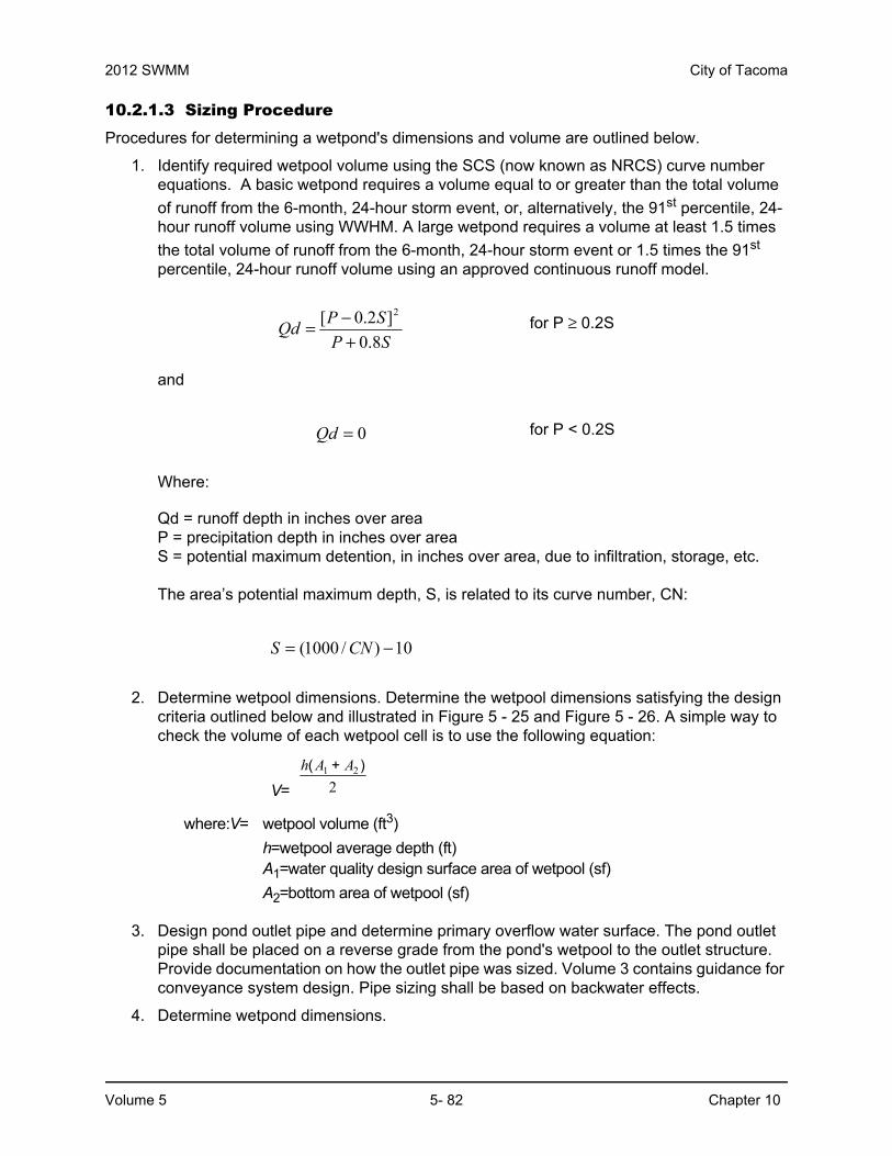
10.2.1.3 Sizing Procedure Procedures for determining a wetpond's dimensions and volume are outlined below.
1. Identify required wetpool volume using the SCS (now known as NRCS) curve number equations. A basic wetpond requires a volume equal to or greater than the total volume
of runoff from the 6-month, 24-hour storm event, or, alternatively, the 91st percentile, 24-hour runoff volume using WWHM. A large wetpond requires a volume at least 1.5 times
the total volume of runoff from the 6-month, 24-hour storm event or 1.5 times the 91st percentile, 24-hour runoff volume using an approved continuous runoff model.
SPSPQd8.0
]2.0[ 2
+−= for P ≥ 0.2S
and
0=Qd for P < 0.2S
Where:
Qd = runoff depth in inches over areaP = precipitation depth in inches over areaS = potential maximum detention, in inches over area, due to infiltration, storage, etc.
The area’s potential maximum depth, S, is related to its curve number, CN:
10)/1000( −= CNS
2. Determine wetpool dimensions. Determine the wetpool dimensions satisfying the design criteria outlined below and illustrated in Figure 5 - 25 and Figure 5 - 26. A simple way to check the volume of each wetpool cell is to use the following equation:
V=
h A A( + )1 2
2
where:V= wetpool volume (ft3)
h=wetpool average depth (ft) A1=water quality design surface area of wetpool (sf)
A2=bottom area of wetpool (sf)
3. Design pond outlet pipe and determine primary overflow water surface. The pond outlet pipe shall be placed on a reverse grade from the pond's wetpool to the outlet structure. Provide documentation on how the outlet pipe was sized. Volume 3 contains guidance for conveyance system design. Pipe sizing shall be based on backwater effects.
4. Determine wetpond dimensions.

City of Tacoma 2012 SWMM
Chapter 10 5- 83 Volume 5
10.2.1.4 Wetpool Geometry• Divide the wetpool into two cells separated by a baffle or berm. The first cell shall contain
between 25 to 35 percent of the total wetpool volume. The baffle or berm volume shall not count as part of the total wetpool volume.
• Provide sediment storage in the first cell. The sediment storage shall have a minimum depth of 1-foot. Install a fixed sediment depth monitor in the first cell to gauge sediment accumulation unless an alternative gauging method is proposed.
• The minimum depth of the first cell shall be 4 feet, exclusive of sediment storage requirements. The depth of the first cell may be greater than the depth of the second cell.
• The maximum depth of each cell shall not exceed 8 feet (exclusive of sediment storage in the first cell). Plant pool depths of 3 feet or shallower (second cell) with emergent wetland vegetation (see planting requirements).
• Place inlets and outlets to maximize the flowpath through the facility. The ratio of flowpath length to width from the inlet to the outlet shall be at least 3:1. The flowpath length is defined as the distance from the inlet to the outlet, as measured at mid-depth. The width at mid-depth can be found as follows: width = (average top width + average bottom width)/2.
• Wetponds with wetpool volumes less than or equal to 4,000 cubic feet may be single celled (i.e., no baffle or berm is required). However, it is especially important in this case that the flow path length be maximized. The ratio of flow path length to width shall be at least 4:1 in single celled wetponds, but should preferably be 5:1.
• All inlets shall enter the first cell. For multiple inlets, the length-to-width ratio shall be based on the average flowpath length for all inlets.
• Line the first cell in accordance with the liner requirements contained in Chapter 4.
10.2.1.5 Berms, Baffles, and Slopes• A berm or baffle shall extend across the full width of the wetpool, and tie into the wetpond
side slopes. If the berm embankments are greater than 4 feet in height, the berm must be constructed by excavating a key with dimensions equal to 50 percent of the embankment cross-sectional height and width. This requirement may be waived if recommended by a geotechnical engineer for specific site conditions. The geotechnical analysis shall address situations in which one of the two cells is empty while the other remains full of water.
• The top of the berm may extend to the WQ design water surface or be 1-foot below the WQ design water surface. If at the WQ design water surface, berm side slopes shall be 3H:1V. Berm side slopes may be steeper (up to 2H:1V) if the berm is submerged 1-foot.
• If good vegetation cover is not established on the berm, erosion control measures shall be used to prevent erosion of the berm back-slope when the pond is initially filled.
• The interior berm or baffle may be a retaining wall provided that the design is prepared and stamped by a licensed civil engineer. If a baffle or retaining wall is used, it shall be submerged one foot below the design water surface to discourage access by pedestrians.
• Side slopes shall not exceed a slope of 3H:1V. Moderately undulating slopes are acceptable and can provide a more natural setting for the facility. In general, gentle side slopes improve the aesthetic attributes of the facility and enhance safety.

2012 SWMM City of Tacoma
Volume 5 5- 84 Chapter 10
10.2.1.6 EmbankmentsEmbankments that impound water must comply with the Washington State Dam Safety Regulations (Chapter 173-175 WAC). If the impoundment has a storage capacity (including both water and sediment storage volumes) greater than 10 acre-feet (435,600 cubic feet or 3.26 million gallons) above natural ground level, then dam safety design and review are required by the Department of Ecology. Contact Ecology for information about this regulation.
10.2.1.7 Inlet and OutletSee Figure 5 - 25 and Figure 5 - 26 for details on the following requirements:
• Submerge the inlet to the wetpond with the inlet pipe invert a minimum of two feet from the pond bottom (not including sediment storage). The top of the inlet pipe shall be submerged at least 1-foot, if possible.
• Provide an outlet structure. Either a Type 2 catch basin with a grated opening (“jail house window”) or a manhole with a cone grate (“birdcage”) may be used (see Figure 3 - 15 for an illustration).
• The pond outlet pipe (as opposed to the manhole or type 2 catch basin outlet pipe) shall be back-sloped or have a down-turned elbow, and extend 1 foot below the WQ design water surface.
• Size the pond outlet pipe, at a minimum, to pass the online WQ design flow. The highest invert of the outlet pipe sets the WQ design water surface elevation.
• The overflow criteria for single-purpose (treatment only, not combined with flow control) wetponds are as follows:
◦ The requirement for primary overflow is satisfied by either the grated inlet to the outlet structure or by a birdcage above the pond outlet structure.
◦ The bottom of the grate opening in the outlet structure shall be set at or above the height needed to pass the WQ design flow through the pond outlet pipe. The grate invert elevation sets the overflow water surface elevation.
◦ The grated opening and downstream conveyance shall be sized to pass the 100-year design flow. The capacity of the outlet system shall be sized to pass the peak flow for the conveyance requirements.
• Provide an emergency spillway and design it according to the requirements for detention ponds (see Volume 3, Section 7.1.3).
• The City may require a bypass/shutoff valve to enable the pond to be taken offline for maintenance purposes.
• A gravity drain for maintenance is recommended if grade allows.
◦ The drain invert shall be at least 6 inches below the top elevation of the dividing berm or baffle. Deeper drains are encouraged where feasible, but must be no deeper than 18 inches above the pond bottom.
◦ The drain shall be at least 8 inches (minimum) diameter and shall be controlled by a valve. Use of a shear gate is allowed only at the inlet end of a pipe located within an approved structure.
◦ Provide operational access to the valve to the finished ground surface.
◦ The valve location shall be accessible and well marked with 1-foot of paving placed around the box. It must also be protected from damage and unauthorized operation.

City of Tacoma 2012 SWMM
Chapter 10 5- 85 Volume 5
◦ A valve box is allowed to a maximum depth of 5 feet without an access manhole. If over 5 feet deep, an access manhole or vault is required.
• All metal parts shall be corrosion-resistant. Do not use galvanized materials.
10.2.1.8 Access and Setbacks• All facilities shall be a minimum of 20 feet from any structure, property line, and any
vegetative buffer required by the local government, and 100 feet from any septic tank/drainfield.
• All facilities shall be a minimum of 50 feet from any slope greater than 20 percent. A geotechnical report must address the potential impact of a wetpond on a slope steeper than 20% or if closer than 50 feet.
• Access is the same as for detention ponds (Volume 3).
• If the dividing berm is also used for access, it should be built to sustain loads of up to 80,000 pounds.
10.2.1.9 Planting RequirementsPlanting requirements for detention ponds also apply to wetponds.
• Large wetponds intended for phosphorus control shall not be planted within the cells, as the plants will release phosphorus in the winter when they die off. The bottom and side slopes shall be stabilized to prevent erosion.
• If the second cell of a basic wetpond is 3 feet deep or shallower, the bottom area shall be planted with emergent wetland vegetation. See Table 5 - 14 for recommended emergent wetland plant species for wetponds. The recommendations in Table 5 - 14 are for all of western Washington. Local knowledge should be used to tailor this information to Tacoma as appropriate.
• Cattails (Typha latifolia) shall not be used because they tend to crowd out other species.
• If the wetpond discharges to a phosphorus-sensitive lake or wetland, shrubs that form a dense cover should be planted on slopes above the WQ design water surface on at least three sides. Native vegetation species shall be used in all cases.
10.2.1.10 Recommended Design FeaturesThe following features should be incorporated into the wetpond design where site conditions allow:
• The method of construction of soil/landscape systems can cause natural selection of specific plant species. Consult a soil restoration or wetland soil scientist for site-specific recommendations. The soil formulation will impact the plant species that will flourish or suffer on the site, and the formulation should be such that it encourages desired species and discourages undesired species.
• For wetpool depths in excess of 6 feet, it is recommended that some form of recirculation be provided in the summer, such as a fountain or aerator, to prevent stagnation and low dissolved oxygen conditions.
• A flow length-to-width ratio greater than the 3:1 minimum is desirable. If the ratio is 4:1 or greater, then the dividing berm is not required, and the pond may consist of one cell rather than two. A one-cell pond must provide at least 6-inches of sediment storage depth.
• A tear-drop shape, with the inlet at the narrow end, rather than a rectangular pond is preferred since it minimizes dead zones caused by corners.

2012 SWMM City of Tacoma
Volume 5 5- 86 Chapter 10
• A small amount of base flow is desirable to maintain circulation and reduce the potential for low oxygen conditions during late summer.
• Evergreen or columnar deciduous trees along the west and south sides of ponds are recommended to reduce thermal heating, except that no trees or shrubs may be planted on berms meeting the criteria of dams regulated for safety. In addition to shade, trees and shrubs also discourage waterfowl use and the phosphorus enrichment problems they cause. Trees should be set back so that the branches will not extend over the pond.
• The number of inlets to the facility should be limited; ideally there should be only one inlet. The flowpath length should be maximized from inlet to outlet for all inlets to the facility.
• The access and maintenance road could be extended along the full length of the wetpond and could double as play courts or picnic areas. Placing finely ground bark or other natural material over the road surface would render it more pedestrian friendly.
• The following design features should be incorporated to enhance aesthetics where possible:
◦ Provide pedestrian access to shallow pool areas enhanced with emergent wetland vegetation. This allows the pond to be more accessible without incurring safety risks.
◦ Provide side slopes that are sufficiently gentle to avoid the need for fencing (3H:1V or flatter).
◦ Create flat areas overlooking or adjoining the pond for picnic tables or seating that can be used by residents. Walking or jogging trails around the pond are easily integrated into site design.
◦ Include fountains or integrated waterfall features for privately maintained facilities.
◦ Provide visual enhancement with clusters of trees and shrubs. On most pond sites, it is important to amend the soil before planting since ponds are typically placed well below the native soil horizon in very poor soils. Make sure dam safety restrictions against planting do not apply.
◦ Orient the pond length along the direction of prevailing summer winds (typically west or southwest) to enhance wind mixing.

Table 5 - 14: Emergent Wetland Species Recommended for Wetponds
Species Common Name NotesMaximum
Depth
Inundation to 1-Foot
Agrostis exarata(1) Spike bent grass Prairie to coast 2 feet
Carex stipata Sawbeak sedge Wet ground
Eleocharis palustris Spike rush Margins of ponds, wet meadows 2 feet
Glyceria occidentalis Western mannagrass Marshes, pond margins 2 feet
Juncus tenuis Slender rush Wet soils, wetland margins
Oenanthe sarmentosa Water parsleyShallow water along stream and pond margins; needs saturated soils all summer
Scirpus atrocinctus (formerly S. cyperinus) Woolgrass Tolerates shallow water; tall clumps
Scirpus microcarpus Small-fruited bulrush Wet ground to 18 inches depth 18 inches
Sagittaria latifolia Arrowhead Prairie to coast
Inundation 1 to 2 Feet
Agrostis exarata(1) Spike bent grass Prairie to coast
Alisma plantago-aquatica Water plantain
Eleocharis palustris Spike rush Margins of ponds, wet meadows
Glyceria occidentalis Western mannagrass Marshes, pond margins
Juncus effusus Soft rush Wet meadows, pastures, wetland margins
Scirpus microcarpus Small-fruited bulrush Wet ground to 18 inches depth 18 inches
Sparganium emmersum Bur reed Shallow standing water, saturated soils
Inundation 1 to 3 Feet
Carex obnupta Slough sedge Wet ground or standing water 1.5 to 3 feet
Beckmania syzigachne(1) Western sloughgrass Wet prairie to pond margins
Scirpus acutus(2) Hardstem bulrush Single tall stems, not clumping 3 feet
Scirpus validus(2) Softstem bulrush
Inundation Greater Than 3 Feet
Nuphar polysepalum Spatterdock Deep water 3 to 7.5 feet
Nymphaea odorata(1) White waterlily Shallow to deep ponds 6 feet
City of Tacoma 2012 SWMM
Chapter 10 5- 87 Volume 5
Notes:
(1) Non-native species. Beckmania syzigachne is native to Oregon. Native species are preferred.
(2) Scirpus tubers must be planted shallower for establishment, and protected from foraging waterfowl until established. Emerging aerial stems should project above water surface to allow oxygen transport to the roots.
Primary sources: Municipality of Metropolitan Seattle, Water Pollution Control Aspects of Aquatic Plants, 1990. Hortus Northwest, Wetland Plants for Western Oregon, Issue 2, 1991. Hitchcock and Cronquist, Flora of the Pacific Northwest, 1973.

2012 SWMM City of Tacoma
Volume 5 5- 88 Chapter 10
10.2.1.11 Construction Criteria• Remove sediment that has accumulated in the pond after construction in the drainage
area of the pond is complete (unless used for a liner - see below).
• Sediment that has accumulated in the pond at the end of construction may be used as a liner in excessively drained soils if the sediment meets the criteria for low permeability or treatment liners in keeping with guidance given in Chapter 3. Sediment used for a soil liner must be graded to provide uniform coverage and must meet the thickness specifications in Chapter 3. The sediment must not reduce the design volume of the pond. The pond must be over-excavated initially to provide sufficient room for the sediments to serve as a liner.
10.2.1.12 MaintenancePer Minimum Requirement #10, an operation and maintenance plan shall be prepared for all stormwater management facilities. See Volume 1, Appendix C, Maintenance Checklist #12 for specific maintenance requirements for wet ponds. Maintenance shall be a basic consideration in design and cost-determination of the stormwater management facility.
Any standing water removed during maintenance operation must be disposed of in a City approved manner. See the dewatering requirements in Volume 4 of this manual. Pretreatment may be necessary. Solids must be disposed of in accordance with state and local waste regulations.
Facilities shall be constructed such that the facility can be easily inspected by one person. This may require construction of additional inspection ports or access manholes to allow inspection acces to be opened by one person.

City of Tacoma 2012 SWMM
Chapter 10 5- 89 Volume 5
10.2.2 BMP T1020 Wetvaults10.2.2.1 DescriptionA wetvault is an underground structure similar in appearance to a detention vault, except that a wetvault has a permanent pool of water (wetpool) which dissipates energy and improves the settling of particulate pollutants (see the wetvault details in Figure 5 - 27). Being underground, the wetvault lacks the biological pollutant removal mechanisms, such as algae uptake, present in surface wetponds.
10.2.2.2 Applications and Limitations:A wetvault may be used for commercial, industrial, or roadway projects if there are space limitations precluding the use of other treatment BMPs. The use of wetvaults for residential development is highly discouraged. Combined detention and wetpools are allowed; see BMP T1040.
If oil control is required for a project, a wetvault may be combined with an API oil/water separator.
10.2.2.3 Design Criteria
Sizing Procedure
The wetpool volume for the wetvault shall be equal to or greater than the total volume of runoff
from the 6-month, 24-hour storm event. Alternatively, the 91st percentile, 24-hour runoff volume estimated by WWHM may be used.
Typical design details and concepts for the wetvault are shown in Figure 5 - 27.

2012 SWMM City of Tacoma
Volume 5 5- 90 Chapter 10
Figure 5 - 27. Wetvault

City of Tacoma 2012 SWMM
Chapter 10 5- 91 Volume 5
10.2.2.4 Wetpool GeometrySame as specified for wetponds (see BMP T1010) except for the following two modifications:
• The sediment storage in the first cell shall be an average of 1-foot. Because of the v-shaped bottom, the depth of sediment storage needed above the bottom of the side wall is roughly proportional to vault width according to the schedule below:
Vault WidthSediment Depth
(from bottom of side wall)15’ 10”20’ 9”40’ 6”60’ 4”
• The second cell shall be a minimum of 3 feet deep since planting cannot be used to prevent re-suspension of sediment in shallow water as it can in open ponds.
10.2.2.5 Vault Structure• Separate the vault into two cells by a wall or a removable baffle. If a wall is used, provide
a 5-foot by 10-foot removable maintenance access for both cells. If a removable baffle is used, the following criteria apply:
◦ The baffle shall extend from a minimum of 1-foot above the WQ design water surface to a minimum of 1-foot below the invert elevation of the inlet pipe.
◦ The lowest point of the baffle shall be a minimum of 2 feet from the bottom of the vault, and greater if feasible.
• If the vault is less than 2,000 cubic feet (inside dimensions), or if the length-to-width ratio of the vault pool is 5:1 or greater, the baffle or wall may be omitted and the vault may be one-celled.
• Do not divide the two cells of a wetvault into additional subcells by internal walls. If internal structural support is needed, it is preferred that post and pier construction be used to support the vault lid rather than walls. Any walls used within cells must be positioned so as to lengthen, rather than divide, the flowpath.
• Slope the bottom of the first cell toward the access opening. Slope shall be between 0.5 percent (minimum) and 2 percent (maximum). The second cell may be level (longitudinally) sloped toward the outlet, with a high point between the first and second cells. Sloping the second cell towards the access opening for the first cell is also acceptable. Alternatively, access openings may be positioned a maximum of 10 feet from any location within the vault.
• Slope the vault bottom laterally a minimum of 5 percent from each side towards the center, forming a broad "v" to facilitate sediment removal. Note: More than one "v" may be used to minimize vault depth.
• The City may allow the vault bottom to be flat if removable panels are provided over the entire vault. Removable panels shall be at grade, have stainless steel lifting eyes, and weigh no more than 5 tons per panel.
• The highest point of a vault bottom must be at least 6 inches below the outlet elevation to provide for sediment storage over the entire bottom.
• Evaluate buoyancy of the vault with the results presented in design documentation.

2012 SWMM City of Tacoma
Volume 5 5- 92 Chapter 10
• Wetvaults may be constructed using arch culvert sections provided the top area at the WQ design water surface is, at a minimum, equal to that of a vault with vertical walls designed with an average depth of 6 feet.
• Wetvaults shall conform to the "Materials" and "Structural Stability" criteria specified for detention vaults in Volume 3, Section 7.4.1.
• Where pipes enter and leave the vault below the WQ design water surface, they shall be sealed using water tight seals or couplers.
• Bare galvanized materials shall not be used.
10.2.2.6 Inlet and Outlet• Submerge the inlet to the wetvault. The inlet pipe invert shall be a minimum of 3 feet from
the vault bottom. Submerge the top of the inlet pipe at least 1-foot, if possible.
• Unless designed as an offline facility, the capacity of the outlet pipe and available head above the outlet pipe shall be designed to convey the 100-year design flow for developed site conditions without overtopping the vault. The available head above the outlet pipe must be a minimum of 6 inches.
• The outlet pipe shall be back-sloped or have tee section, the lower arm of which shall extend 1 foot below the WQ design water surface to provide for trapping of oils and floatables in the vault.
• Center the inlet and outlet pipes over the “V” portion of the vault.
10.2.2.7 Access RequirementsSame as for detention vaults (see Volume 3, Section 7.4.1.4), except for the following additional requirement for wetvaults:
• Provide a minimum of 50 square feet of grate over the second cell. For vaults in which the surface area of the second cell is greater than 1,250 square feet, grate 4 percent of the top. This requirement may be met by one grate or by many smaller grates distributed over the second cell area.
NOTE: A grated access door can be used to meet this requirement.
10.2.2.8 Access Roads, Right of Way, and SetbacksSame as for detention vaults (see Volume 3, Section 7.4.1.4).
10.2.2.9 Recommended Design FeaturesThe following design features should be incorporated into wetvaults where feasible, but they are not specifically required:
• The floor of the second cell should slope toward the outlet for ease of cleaning.
• The inlet and outlet should be at opposing corners of the vault to increase the flowpath.
• A flow length-to-width ratio greater than 3:1 minimum is desirable.
• Lockable grates instead of solid manhole covers are recommended to increase air contact with the wetpool.
• The number of inlets to the wetvault should be limited, and the flowpath length should be maximized from inlet to outlet for all inlets to the vault.

City of Tacoma 2012 SWMM
Chapter 10 5- 93 Volume 5
10.2.2.10 Construction CriteriaRemove sediment that has accumulated in the vault after construction in the drainage area is complete.
10.2.2.11 MaintenancePer Minimum Requirement #10, an operation and maintenance plan shall be prepared for all stormwater management facilities. See Volume 1, Appendix C, Maintenance Checklist #14 for specific maintenance requirements for wet vaults. Maintenance shall be a basic consideration in design and cost-determination of the stormwater management facility.
Any standing water removed during maintenance operation must be disposed of in a City approved manner. See the dewatering requirements in Volume 4 of this manual. Pretreatment may be necessary. Solids must be disposed of in accordance with state and local waste regulations.
Facilities shall be constructed such that the facility can be easily inspected by one person. This may require construction of additional inspection ports or access manholes to allow inspection acces to be opened by one person.
10.2.2.12 Modifications for Combining with a Baffle Oil/Water SeparatorIf the project site is a high-use site and a wetvault is proposed, the vault may be combined with a baffle oil/water separator to meet the runoff treatment requirements with one facility rather than two.
• The sizing procedures for the baffle oil/water separator (Chapter 9) shall be run as a check to ensure the vault is large enough. If the oil/water separator sizing procedures result in a larger vault size, increase the wetvault size to match.
• An oil retaining baffle shall be provided in the second cell near the vault outlet. The baffle shall not contain a high-flow overflow, or else the retained oil will be washed out of the vault during large storms.
• The vault shall have a minimum length-to-width ratio of 5:1.
• The vault shall have a design water depth-to-width ratio of between 1:3 to 1:2.
• The vault shall be watertight and shall be coated to protect from corrosion.
• Separator vaults shall have a shutoff mechanism on the outlet pipe to prevent oil discharges during maintenance and to provide emergency shut-off capability in case of a spill. Also, provide a valve box and riser.
• Wetvaults used as oil/water separators must be offline and must bypass flows greater than the offline WQ design flow multiplied by 3.5. This will minimize the entrainment and/or emulsification of previously captured oil during very high flow events.

2012 SWMM City of Tacoma
Volume 5 5- 94 Chapter 10
10.2.3 BMP T1030 Stormwater Treatment Wetlands10.2.3.1 DescriptionStormwater treatment wetlands are shallow man-made ponds that are designed to treat stormwater through the biological processes associated with emergent aquatic plants (see the stormwater wetland details in Figure 5 - 28 and Figure 5 - 29).
Wetlands created to mitigate disturbance impacts, such as filling of wetlands, shall not be used as stormwater treatment facilities.
10.2.3.2 Applications and LimitationsThe most critical factor for a successful design is the provision of an adequate supply of water for most of the year. Since water depths are shallower than in wetponds, water loss by evaporation is an important concern. Stormwater wetlands are a good WQ facility choice in areas with high winter groundwater levels.
10.2.3.3 Design CriteriaStormwater wetlands use most of the same design criteria as wetponds. However, instead of gravity settling being the dominant treatment process, pollutant removal mediated by aquatic vegetation and the microbiological community associated with that vegetation becomes the dominant treatment process. Thus when designing wetlands, water volume is not the dominant design criteria. Rather, factors which affect plant vigor and biomass are the primary concerns.
10.2.3.4 Sizing Procedure1. The design volume is the total volume of runoff from the 6-month, 24-hour storm event or,
alternatively, the 91st percentile, 24-hour runoff volume using WWHM.
2. Calculate the surface area of the stormwater wetland. The surface area of the wetland shall be the same as the top area of a wetpond sized for the same site conditions. Calculate the surface area of the stormwater wetland by using the volume from Step 1 and dividing by the average water depth (use 3 feet).
3. Determine the surface area of the first cell of the stormwater wetland. Use the volume determined from Criterion 2 under "Wetland Geometry", below, and the actual depth of the first cell.
4. Determine the surface area of the wetland cell. Subtract the surface area of the first cell (Step 3) from the total surface area (Step 2).
5. Determine water depth distribution in the second cell. Decide if the top of the dividing berm will be at the surface or submerged (designer's choice). Adjust the distribution of water depths in the second cell according to Step 8 in Section 10.2.3.5. This will result in a facility that holds less volume than that determined in Step 1 above. This is acceptable.
6. Choose plants. See Table 5 - 14 for a list of plants recommended for wetpond water depth zones, or consult a wetland scientist.

City of Tacoma 2012 SWMM
Chapter 10 5- 95 Volume 5
10.2.3.5 Wetland Geometry1. Stormwater wetlands shall consist of two cells, a presettling cell and a wetland cell.
2. The presettling cell shall contain approximately 33 percent of the wetpool volume calculated in Step 1 above.
3. The depth of the presettling cell shall be between 4 feet (minimum) and 8 feet (maximum), excluding sediment storage.
4. Provide one-foot of sediment storage in the presettling cell.
5. The wetland cell shall have an average water depth of about 1.5 feet (plus or minus 3 inches).
6. Shape the "berm" separating the two cells such that its downstream side gradually slopes to form the second shallow wetland cell (see the section view in Figure 5 - 28). Alternatively, the second cell may be graded naturalistically from the top of the dividing berm (see Step 8 below).
7. The top of the berm shall be either at the WQ design water surface or submerged 1-foot below the WQ design water surface. Correspondingly, the side slopes of the berm must meet the following criteria:
a. If the top of berm is at the WQ design water surface, the berm side slopes shall be no steeper than 3H:1V.
b. If the top of berm is submerged 1-foot, the upstream side slope may be up to 2H:1V.
8. Grade the bottom of the wetland cell in one of two ways:
a. Shallow evenly graded slope from the upstream to the downstream edge of the wetland cell (see Figure 5 - 28).
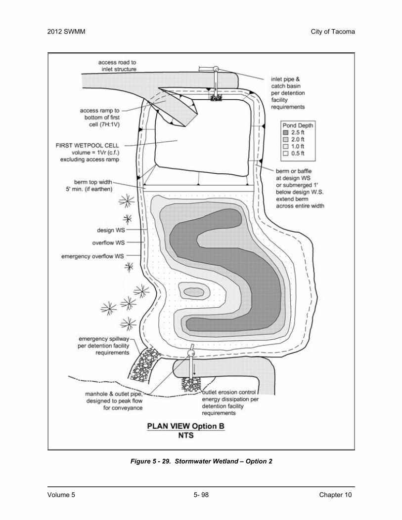
b. A "naturalistic" alternative, with the specified range of depths intermixed throughout the second cell (see Figure 5 - 29). A distribution of depths shall be provided in the wetland cell depending on whether the dividing berm is at the water surface or submerged (see 2).
The maximum depth shall be 2.5 feet in either configuration.
10.2.3.6 Lining RequirementsIn infiltrative soils, line both cells of the stormwater wetland. To determine whether a low-permeability liner or a treatment liner is required, determine whether the following conditions will be met. If soil permeability will allow sufficient water retention, lining may be waived.
1. The second cell must retain water for at least 10 months of the year.
2. The first cell must retain at least three feet of water year-round.
3. Use a complete precipitation record when establishing these conditions. Take into account evapotranspiration losses as well as infiltration losses. Many wetland plants can adapt to periods of summer drought, so a limited drought period is allowed in the second cell. This may allow a treatment liner rather than a low permeability liner to be used for the second cell. The first cell must retain water year-round in order for the presettling function to be effective.

2012 SWMM City of Tacoma
Volume 5 5- 96 Chapter 10
4. If a low permeability liner is used, place a minimum of 18 inches of native soil amended with good topsoil or compost (one part compost mixed with 3 parts native soil) over the liner. For geomembrane liners, a soil depth of 3 feet is recommended to prevent damage to the liner during planting. Hydric soils are not required.
The criteria for liners given in Chapter 4 must be observed.
10.2.3.7 Inlet and OutletSame as for wetponds (see BMP T1010).
10.2.3.8 Access and SetbacksAcces shall be the same as for detention ponds.

������������ �����������������������������������������
City of Tacoma 2012 SWMM
Chapter 10 5- 97 Volume 5
Figure 5 - 28. Stormwater Wetland – Option 1
2012 SWMM City of Tacoma
Volume 5 5- 98 Chapter 10
Figure 5 - 29. Stormwater Wetland – Option 2

Table 5 - 15: Distribution of Depths in Wetland Cell
Dividing Berm at WQ Design Water Surface Dividing Berm Submerged 1-Foot
Depth Range (feet) Percent Depth Range (feet) Percent
0.1 to 1 25 1 to 1.5 40
1 to 2 55 1.5 to 2 40
2 to 2.5 20 2 to 2.5 20
City of Tacoma 2012 SWMM
Chapter 10 5- 99 Volume 5
10.2.3.9 Planting RequirementsPlant the wetland cell with emergent wetland plants following the recommendations given in Table 5 - 14 or the recommendations of a wetland specialist. Cattails (Typha latifolia) are not allowed.
10.2.3.10 Construction Criteria• Construction and maintenance considerations are the same as for wetponds.
• Construction of the naturalistic alternative (Option 2) can be accomplished by first excavating the entire area to the 1.5-foot average depth. Then soil subsequently excavated to form deeper areas can be deposited to raise other areas until the distribution of depths indicated in the design is achieved.
10.2.3.11 Maintenance Per Minimum Requirement #10, an operation and maintenance plan shall be prepared for all stormwater management facilities. See Volume 1, Appendix C, Maintenance Checklist #13 for specific maintenance requirements for treatment wetlands. Maintenance shall be a basic consideration in design and cost-determination of the stormwater management facility.
Any standing water removed during maintenance operation must be disposed of in a City approved manner. See the dewatering requirements in Volume 4 of this manual. Pretreatment may be necessary. Solids must be disposed of in accordance with state and local waste regulations.
Facilities shall be constructed such that the facility can be easily inspected by one person. This may require construction of additional inspection ports or access manholes to allow inspection acces to be opened by one person.

2012 SWMM City of Tacoma
Volume 5 5- 100 Chapter 10
10.2.4 BMP T1040 Combined Detention and Wetpool Facilities10.2.4.1 DescriptionCombined detention and WQ wetpool facilities have the appearance of a detention facility but contain a permanent pool of water as well. The following design procedures, requirements, and recommendations cover differences in the design of the stand-alone WQ facility when combined with detention storage. The following combined facilities are addressed:
• Detention/wetpond (basic and large)
• Detention/wetvault
• Detention/stormwater wetland.
There are two sizes of the combined wetpond, a basic and a large, but only a basic size for the combined wetvault and combined stormwater wetland. The facility sizes (basic and large) are related to the pollutant removal goals. See Chapter 3 for more information about treatment performance goals.
10.2.4.2 Applications and Limitations:Combined detention and water quality facilities are efficient for sites that also have detention requirements. The water quality facility may often be placed beneath the detention facility without increasing the facility surface area. However, the fluctuating water surface of the live storage will create unique challenges for plant growth and for aesthetics alike.
The live storage component of the facility shall be provided above the seasonal high water table.
10.2.4.3 Design CriteriaTypical design details and concepts for a combined detention and wetpond are shown in Figure 5 - 30 and Figure 5 - 31. The detention portion of the facility shall meet the design criteria and sizing procedures set forth in Volume 3.

City of Tacoma 2012 SWMM
Chapter 10 5- 101 Volume 5
Figure 5 - 30. Combined Detention and Wetpond (top view)

���� ������������������ ����������������������������������������������������
2012 SWMM City of Tacoma
Volume 5 5- 102 Chapter 10
Figure 5 - 31. Combined Detention and Wetpond (side view)
10.2.4.4 Sizing The sizing for combined detention and wetponds are identical to those for wetponds and for detention facilities. The wetpool volume for a combined facility shall be equal to or greater than
the total volume of runoff from the 6-month, 24-hour storm event or the 91st percentile 24-hour runoff volume estimated by WWHM. Follow the standard procedure specified in Volume 3 to size the detention portion of the pond.

City of Tacoma 2012 SWMM
Chapter 10 5- 103 Volume 5
10.2.4.5 Detention and Wetpool Geometry• Do not include the wetpool and sediment storage volumes in the required detention
volume.
• The "Wetpool Geometry" criteria for wetponds (see BMP T1010) shall apply with the following modifications/clarifications:
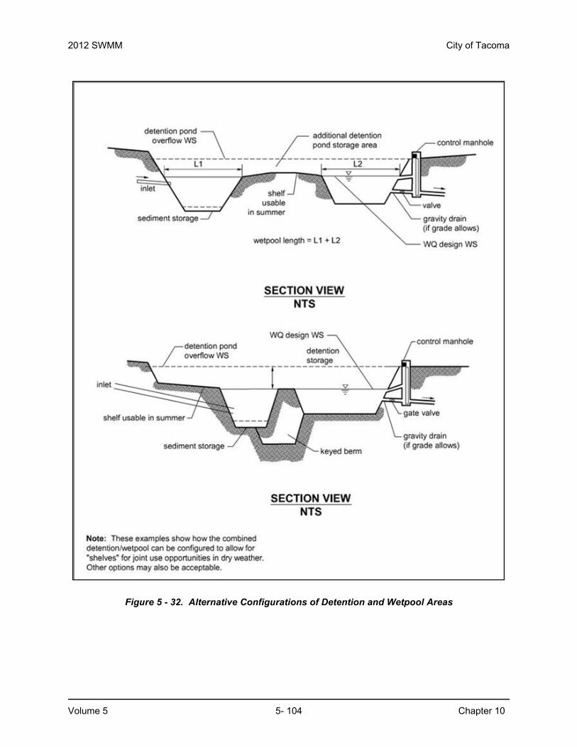
◦ The permanent pool may be shallower to comprise most of the pond bottom, or deeper positioned to comprise a limited portion of the bottom. Note, having the first wetpool cell at the inlet allows for more efficient sediment management than if the cell is moved away from the inlet. Wetpond criteria governing water depth must still be met. See Figure 5 - 32 for two possibilities for wetpool cell placement.
◦ The minimum sediment storage depth in the first cell is 1-foot. The 6 inches of sediment storage required for a detention pond does not need to be added to this, but 6 inches of sediment storage must be added to the second cell to comply with the detention sediment storage requirement.
10.2.4.6 Berms, Baffles and SlopesSame as for wetponds (see BMP T1010)
10.2.4.7 Inlet and OutletThe Inlet and Outlet criteria for wetponds shall apply with the following modifications:
• Provide a sump in the outlet structure of combined ponds.
• Design the detention flow restrictor and its outlet pipe according to the requirements for detention ponds (see Volume 3).
10.2.4.8 Access and SetbacksThe same as for wetponds.
10.2.4.9 Planting RequirementsThe same as for wetponds.
10.3 Combined Detention and WetvaultThe sizing procedure for combined detention and wetvaults is identical to those outlined for wetvaults and for detention facilities. The design criteria for detention vaults and wetvaults must both be met, except for the following modifications or clarifications:
• The minimum sediment storage depth in the first cell shall average 1-foot. The 6 inches of sediment storage required for detention vaults do not need to be added to this, but 6 inches of sediment storage must be added to the second cell to comply with detention vault sediment storage requirements.
• The oil retaining baffle shall extend a minimum of 2 feet below the WQ design water surface.
• If a vault is used for detention as well as water quality control, the facility may not be modified to function as a baffle oil/water separator as allowed for wetvaults in BMP T1020.
2012 SWMM City of Tacoma
Volume 5 5- 104 Chapter 10
Figure 5 - 32. Alternative Configurations of Detention and Wetpool Areas

City of Tacoma 2012 SWMM
Chapter 10 5- 105 Volume 5
10.4 Combined Detention and Stormwater Wetland
10.4.1 Sizing CriteriaThe sizing procedure for combined detention and stormwater wetlands is identical to those outlined for stormwater wetlands and for detention facilities. Follow the procedure specified in BMP T1030 to determine the stormwater wetland size. Follow the standard procedure specified in Volume 3 to size the detention portion of the wetland.
Water Level Fluctuation Restrictions: The difference between the WQ design water surface and the maximum water surface associated with the 2-year runoff shall not be greater than 3 feet. If this restriction cannot be met, the size of the stormwater wetland must be increased. The additional area may be placed in the first cell, second cell, or both. If placed in the second cell, the additional area need not be planted with wetland vegetation or counted in calculating the average depth.
10.4.2 Design CriteriaThe design criteria for detention ponds and stormwater wetlands must both be met, except for the following modifications or clarifications The Wetland Geometry criteria for stormwater wetlands (see BMP T1030) shall be modified as follows:
• The minimum sediment storage depth in the first cell is 1-foot. The 6 inches of sediment storage required for detention ponds does not need to be added to this, nor does the 6 inches of sediment storage in the second cell of detention ponds need to be added.
10.4.3 Inlet and Outlet CriteriaThe Inlet and Outlet criteria for wetponds shall apply with the following modifications:
• Provide a sump in the outlet structure of combined facilities.
• Design the detention flow restrictor and its outlet pipe according to the requirements for detention ponds (see Volume 3).
10.4.4 Planting RequirementsThe Planting Requirements for stormwater wetlands are modified to use the following plants which are better adapted to water level fluctuations:
• Scirpus acutus (hardstem bulrush) 2 - 6' depth
• Scirpus microcarpus (small-fruited bulrush) 1 - 2.5' depth
• Sparganium emersum (burreed) 1 - 2' depth
• Sparganium eurycarpum (burreed) 1 - 2' depth
• Veronica sp. (marsh speedwell) 0 - 1' depth
In addition, the shrub Spirea douglasii (Douglas spirea) may be used in combined facilities.