chapter 9 creep of intermetallics - concordia...
TRANSCRIPT

Chapter 9
Creep of Intermetallics
9.1 INTRODUCTION
The term ‘‘intermetallics’’ has been used to designate the intermetallic phases and
compounds which result from the combination of various metals, and which form a
large class of materials [598]. There are mainly three types of superlattice structures
based on the f.c.c. lattice, i.e. L12 (with a variant of L012 in which a small interstitial
atom of C or N is inserted at the cube center), L10, and L12-derivative long-period
structures such as DO22 or DO23. The b.c.c.-type structures are B2 and DO3 or L21.
The DO19 structure is one of the most typical superlattices based on h.c.p. symmetry.
Table 4 lists the crystal structure, lattice parameter and density of selected inter-
metallic compounds [599]. A comprehensive review on the physical metallurgy and
processing of intermetallics can be found in [600].
Intermetallics often have high melting temperatures (usually higher than 1000�C),
due partly to the strong bonding between unlike atoms, which is, in general, a mixture
between metallic, ionic and covalent to different extents. The presence of these strong
bonds also results in high creep resistance. Another factor that contributes to the
superior strength of intermetallics at elevated temperature is the high degree of long-
range order [602]. The effect of order is, first, to slow diffusivity. The reason for this
is that the number of atoms per unit cell is large in a material with long-range order.
Therefore in alloys in which dislocation climb is rate-controlling, a decrease in
the diffusion rate would result in a drop in the creep rate and therefore in an increase
Table 4. Crystal structure, lattice parameters and density of selected intermetallic compounds.
Alloy
Structure
(Bravais lattice)
Lattice Parameters
Density
(g/cm3)a (nm) c (nm)
Ni3Al L12 (simple cubic) 0.357 – 7.40
NiAl B2 (simple cubic) 0.288 – 5.96
Ni2AlTi DO3 0.585 – 6.38
Ti3Al DO19 0.577 0.464 4.23
TiAl L10 0.398 0.405 3.89
Al3Ti DO22 0.395 0.860 3.36
FeAl B2 (simple cubic) 5.4–6.7 [601]
Fe3Al DO3 5.4–6.7 [601]
MoSi2 C11b 6.3
173
of the creep resistance. Secondly, the presence of a high degree of long-range order
may retard the viscous motion of dislocations. This is due to the fact that, when a
dislocation moves in a non-perfect lattice, the long-range order is damaged and this
leads to an increase in energy or a dragging force. Thus, the presence of order results
in a decrease of the creep rate in the intermetallic alloys in which the mechanism of
viscous glide of dislocations is rate-controlling.
One major disadvantage of these materials, that is limiting their industrial
application, is brittleness [603]. This is attributed to several factors. First, the strong
atomic bonds as well as the long-range order give rise to high Peierls stresses.
Transgranular cleavage will occur in a brittle manner if the latter are larger than
the stress for nucleation of a crack. Second, grain boundaries are intrinsically weak.
The low boundary cohesion results in part from the directionality of the distribution
of the electronic charge in ordered alloys [600]. The strong atomic bonding between
the two main alloy constituents is related to the p-d orbital hibridization, which
leads to a strong directionality in the charge distribution. In grain boundaries
the directionality is reduced and thus the bonding becomes much weaker.
Other factors that may contribute to the brittleness in intermetallics are the limited
number of operative slip systems, segregation of impurities at grain boundaries, a
high work hardening rate, planar slip, and the presence of constitutional defects. The
latter may be, for example, atoms occupying sites of a sublattice other than their
own sublattice (antisites) or vacancies of deficient atomic species (constitutional
vacancies). The planar faults, dislocation dissociations, and dislocation core
structures typical of intermetallics were summarized by Yamaguchi and Umakoshi
[604]. Other so-called extrinsic factors that cause brittleness are the presence of
segregants, interstitials, moisture in the environment, poor surface finish, and
hydrogen [605]. It appears that those intermetallics with more potential as high-
temperature structural materials, i.e., those which are less brittle, are compounds
with high crystal symmetry and small unit cells. Thus, Nickel aluminides, Titanium
Aluminides, and Iron aluminides have been the subject of the most activities in
research and development over the last two decades. These investigations were
stimulated by both the possibility of industrial application and scientific interest
[598–607].
Creep resistance is a critical property in materials used for high temperature
structural applications. Some intermetallics may have the potential to replace nickel
superalloys in parts such as the rotating blades of gas turbines or jet engines [608]
due to their higher melting temperatures, high oxidation and corrosion resistance,
high creep resistance, and, in some cases, lower density. The creep behavior of
intermetallics is more complicated than that of pure metals and disordered
solid solution alloys due to their complex structures together with the varieties of
chemical composition [609–610]. The rate-controlling mechanisms are still not
174 Fundamentals of Creep in Metals and Alloys

fully understood in spite of significant efforts over the last couple of decades
[598,604,611–619].
In the following, the current understanding of creep of intermetallics will be
reviewed, placing special emphasis on investigations published over the last decade
and related to the compounds with potential for structural applications such as
Titanium Aluminides, Iron aluminides and Nickel aluminides.
9.2 TITANIUM ALUMINIDES
9.2.1 Introduction
Titanium aluminide alloys have the potential for replacing heavier materials in high-
temperature structural applications such as automotive and aerospace engine
components. This is due, first, to their low density (lower than that of most other
intermetallics), high melting temperature, good elevated temperature strength and
high modulus, high oxidation resistance and favorable creep properties [620,621].
Second, they can be processed through conventional manufacturing methods such as
casting, forging and machining [607]. In fact, TiAl turbocharger turbine wheels have
recently been used in automobiles [607]. Table 5 (from [621]) compares the properties
between Titanium Aluminides, titanium-based conventional alloys and superalloys
(see phase diagram below for phase compositions).
Many investigations have attempted to understand the creep mechanisms in
Titanium Aluminides over the last two decades. Several excellent reviews in this area
include [607,622,623]. The creep behavior of Titanium Aluminides depends strongly
Table 5. Properties of Titanium Aluminides, titanium-based conventional alloys and superalloys.
Property
Ti-based
alloys
Ti3Al-based
a2 alloysTiAl-based
g alloys superalloys
Density (g/cm3) 4.5 4.1–4.7 3.7–3.9 8.3
RT modulus (GPa) 96–115 120–145 160–176 206
RT Yield strength (MPa) 380–1115 700–990 400–630 250–1310*
RT Tensile strength (MPa) 480–1200 800–1140 450–700 620–1620*
Highest temperature with
high creep strength (�C)
600 750 1000 1090
Temperature of oxidation (�C) 600 650 900–1000 1090
Ductility (%) at RT 10–20 2–7 1–3 3–5
Ductility (%) at high T High 10–20 10–90 10–20
Structure hcp/bcc DO19 L10 Fcc/L12
*Data added to the table provided in [621].
Creep of Intermetallics 175
on alloy composition and microstructure. The different Ti-Al microstructures are
briefly reviewed in the following sections.
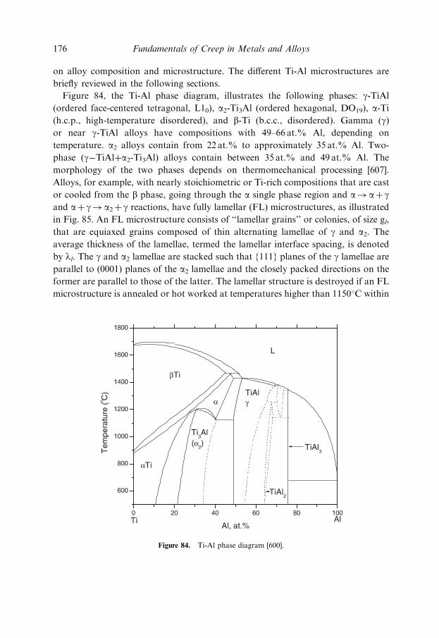
Figure 84, the Ti-Al phase diagram, illustrates the following phases: g-TiAl
(ordered face-centered tetragonal, L10), a2-Ti3Al (ordered hexagonal, DO19), a-Ti(h.c.p., high-temperature disordered), and b-Ti (b.c.c., disordered). Gamma (g)or near g-TiAl alloys have compositions with 49–66 at.% Al, depending on
temperature. a2 alloys contain from 22 at.% to approximately 35 at.% Al. Two-
phase (g�TiAlþa2-Ti3Al) alloys contain between 35 at.% and 49 at.% Al. The
morphology of the two phases depends on thermomechanical processing [607].
Alloys, for example, with nearly stoichiometric or Ti-rich compositions that are cast
or cooled from the b phase, going through the a single phase region and a!aþ gand aþ g! a2þ g reactions, have fully lamellar (FL) microstructures, as illustrated
in Fig. 85. An FL microstructure consists of ‘‘lamellar grains’’ or colonies, of size gl,
that are equiaxed grains composed of thin alternating lamellae of g and a2. Theaverage thickness of the lamellae, termed the lamellar interface spacing, is denoted
by ll. The g and a2 lamellae are stacked such that {111} planes of the g lamellae are
parallel to (0001) planes of the a2 lamellae and the closely packed directions on the
former are parallel to those of the latter. The lamellar structure is destroyed if an FL
microstructure is annealed or hot worked at temperatures higher than 1150�C within
Figure 84. Ti-Al phase diagram [600].
176 Fundamentals of Creep in Metals and Alloys

the (aþg) phase fields. A bimodal microstructure develops, consisting of lamellar
grains alternating with g grains (or grains exclusively of g-phase). Depending on the
amount of g-grains, the microstructure is termed ‘‘nearly lamellar’’ (NL) when the
fraction of g-grains is small, or duplex (DP) when the fractions of lamellar and
g-grains are comparable. Detailed studies of the microstructures of TiAl alloys
are described in [624–625].
Overall, two-phase g-TiAl alloys have more potential for high-temperature
applications than a-Ti3Al alloys due to their higher oxidation resistance and Elastic
Modulus [621]. Simultaneously, two-phase g-TiAl alloys have comparatively lower
creep strength at high temperature than a-Ti3Al alloys and therefore significant
efforts have been devoted in recent years to improve the creep behavior of g-TiAl. It
is now well established that the optimum microstructure for creep resistance in two-
phase TiAl alloys is fully lamellar (FL) [626–628]. As will be explained in the
following sections, this microstructure shows the highest creep resistance, the lowest
minimum creep rate, and the best primary creep behavior (i.e., longer times to attain
a specified strain). Figure 86 (from [626]) illustrates the creep curves at 760�C and
240 MPa corresponding to a Ti-48%Al alloy with several different microstructures.
The FL microstructure shows superior creep resistance. Lamellar microstructures
also have superior fracture toughness and fatigue resistance in comparison to duplex
(DP) structures, although the latter have, in general, better ductility [607]. This
section will review the fundamentals of creep deformation in FL Ti-Al alloys.
Emphasis will be placed on describing prominent recent creep models, rather than on
compiling the extensive experimental data [622,623,626].
Figure 85. Fully lamellar (FL) microstructure corresponding to a Ti-Al based alloy with a nearly
stoichiometric composition [607].
Creep of Intermetallics 177

9.2.2 Rate Controlling Creep Mechanisms in FL TiAl
Intermetallics During ‘‘Secondary’’ Creep
Several investigations have attempted to determine the rate-controlling mechanisms
during creep of fully lamellar TiAl intermetallics [622–623,626–633]. Most creep
studies were performed in the temperature range 676�C–877�C [623] and the stress
range 80–500MPa, relevant to the anticipated service conditions [629]. Clarifying
the rate controlling creep mechanisms in FL TiAl alloys is difficult for several
reasons. First, rationalization of creep data by conventional methods such as
analysis of steady-state stress exponents is controversial, since usually an
unambiguous secondary creep stage is not observed. Instead, a minimum strain
rate (_eemin) is measured, and the ‘‘secondary creep rate’’ or ‘‘steady-state rate’’ is
presumed close to the minimum rate. Second, a continuous increase in the slope of
the curve is observed (i.e., the stress exponent increases steadily as stress increases)
when minimum strain-rates are plotted versus modulus-compensated stress over a
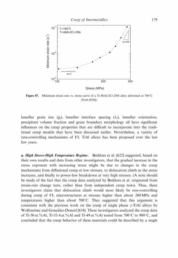
wide stress-range. Figure 87 illustrates a minimum strain rate vs. stress plot for a FL
Ti-48Al-2Cr-2Nb at 760�C. The stress exponent varies from n¼ 1, at low stresses, to
n¼ 10 at high stresses. Stress exponents as high as 20 have been measured at elevated
stresses [621]. Third, the analysis of creep data is a very difficult task because of the
complex microstructures of FL TiAl alloys. Microstructural parameters such as
Figure 86. Creep curves at 760�C and 240MPa corresponding to several near g-TiAl alloys with different
microstructures. (a) Ti-48Al alloy with a fully lamellar (FL) microstructure; (b) Ti-48Al alloy with a nearly
lamellar (NL) microstructure; (c) Ti-48Al alloy with a duplex microstructure [626].
178 Fundamentals of Creep in Metals and Alloys
lamellar grain size (gl), lamellar interface spacing (ll), lamellar orientation,
precipitate volume fraction and grain boundary morphology all have significant
influences on the creep properties that are difficult to incorporate into the tradi-
tional creep models that have been discussed earlier. Nevertheless, a variety of
rate-controlling mechanisms of FL TiAl alloys has been proposed over the last
few years.
a. High Stress-High Temperature Regime. Beddoes et al. [622] suggested, based on
their own results and data from other investigators, that the gradual increase in the
stress exponent with increasing stress might be due to changes in the creep
mechanisms from diffusional creep at low stresses, to dislocation climb as the stress
increases, and finally to power-law breakdown at very high stresses. (A note should
be made of the fact that the creep data analyzed by Beddoes et al. originated from
strain-rate change tests, rather than from independent creep tests). Thus, these
investigators claim that dislocation climb would most likely be rate-controlling
during creep of FL microstructures at stresses higher than about 200MPa and
temperatures higher than about 700�C. They suggested that this argument is
consistent with the previous work on the creep of single phase g-TiAl alloys by
Wolfenstine and Gonzalez-Doncel [634]. These investigators analyzed the creep data
of Ti-50 at.%Al, Ti-53.4 at.%Al and Ti-49 at.%Al tested from 700�C to 900�C, and
concluded that the creep behavior of these materials could be described by a single
Figure 87. Minimum strain rate vs. stress curve of a Ti-48Al-2Cr-2Nb alloy deformed at 760�C
(from [626]).
Creep of Intermetallics 179
mechanism by incorporating a threshold stress. The stress exponent was found to be
close to 5 and the activation energy equal to 313 kJ/mol, a value close to that for
lattice diffusion of Ti in g-TiAl (291 kJ/mole) [635]. Additionally, several other
studies on creep of FL TiAl alloys reported activation energies of roughly 300 kJ/
mole [635]. Therefore the creep of FL TiAl alloys appears to be controlled by lattice
diffusion of Ti. The activation energy for lattice diffusion of Al in g-TiAl has not
been measured but it is believed to be significantly higher than that of Ti [636].
Es-Souni et al. [627] also suggested the predominance of a recovery-type dislocation-
climb mechanism based on microstructural observations of the formation of
dislocation arrangements (similar to subgrains) during creep. Several possible
explanations have been suggested to reconcile the proposition of dislocation climb
and the observation of high stress exponents (n>5). First, it has been suggested
[622] that back-stresses may arise within lamellar microstructures due to the trapping
of dislocation segments at the lamellar interfaces, which leads to bowing of
dislocations between interfaces. The shear stress required to cause bowing, which
was suggested as a source of backstresses during creep, is inversely proportional to
the lamellar interface spacing (ll). Second, it has been proposed [637] that the
occurrence of microstructural instabilities such as dynamic recrystallization during
deformation may contribute to a rise in the strain rate, thus rendering stress
exponents with less physical meaning in terms of a single, rate-controlling
restoration mechanism. Finally, it has been suggested [622] that the Subgrain size
corresponding to a specific creep stress if dislocation climb were rate-controlling
could be larger than the lamellar spacing, ll, which remains constant with stress.
Thus, ll may actually become the ‘‘effective Subgrain size’’. These circumstances are
similar to constant structure creep, which is associated with a relatively high stress
exponent of 8 or higher.
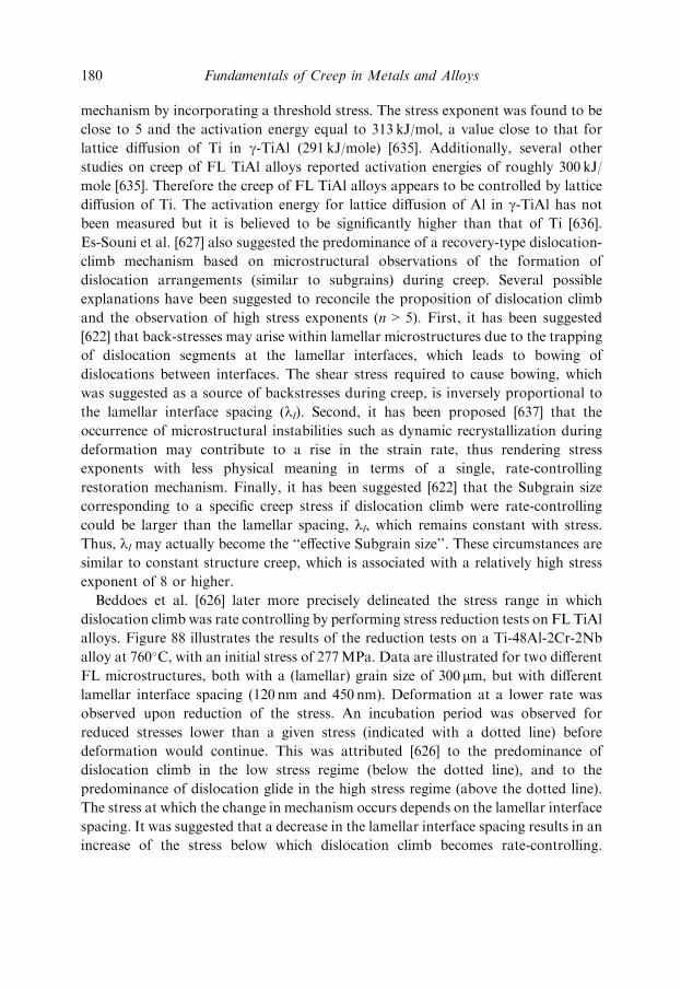
Beddoes et al. [626] later more precisely delineated the stress range in which
dislocation climb was rate controlling by performing stress reduction tests on FL TiAl
alloys. Figure 88 illustrates the results of the reduction tests on a Ti-48Al-2Cr-2Nb
alloy at 760�C, with an initial stress of 277MPa. Data are illustrated for two different
FL microstructures, both with a (lamellar) grain size of 300 mm, but with different
lamellar interface spacing (120 nm and 450 nm). Deformation at a lower rate was
observed upon reduction of the stress. An incubation period was observed for
reduced stresses lower than a given stress (indicated with a dotted line) before
deformation would continue. This was attributed [626] to the predominance of
dislocation climb in the low stress regime (below the dotted line), and to the
predominance of dislocation glide in the high stress regime (above the dotted line).
The stress at which the change in mechanism occurs depends on the lamellar interface
spacing. It was suggested that a decrease in the lamellar interface spacing results in an
increase of the stress below which dislocation climb becomes rate-controlling.
180 Fundamentals of Creep in Metals and Alloys

Beddoes et al. [626] proposed an explanation for the decrease in the minimum creep
rate with decreasing lamellar interface spacing for a given stress. First, for two
microstructures deforming in the glide-controlled creep regime (for example, for
stresses higher than 190MPa in Fig. 88), narrower spacings would increase the creep
resistance since the mean free path for dislocations would significantly decrease. The
lamellae interfaces would thus act as obstacles for gliding dislocations. In fact,
dislocation pile-ups have been observed at interfaces in FL structures [628]. Second,
there is a stress range (for example, stresses between 130MPa and 190MPa in Fig. 88)
for which the rate-controlling creep mechanism in microstructures with very narrow
lamellae would be dislocation climb (associated with lower strain-rates) whereas in
others with wider lamellae it would be dislocation glide. This was attributed to the
different backstresses originating at lamellae of different thickness. A larger Orowan
stress is necessary to bow dislocations in narrow lamellae than in wider lamellae.
Thus, an applied stress of 130–190MPa would be high enough to cause dislocation
bowing in the material with wider lamellae. Dislocation glide would be controlled by
the interaction between dislocations and interfaces rather than climb. However, in
narrower lamellae, the applied stress is not sufficient to cause dislocation bowing and
dislocation movement is then controlled by climb.
Recently Viswanathan et al. [638,639] studied the creep properties of a FL
Ti-48Al-2Cr-2Nb alloy at high stresses (207MPa) and high temperatures (around
Figure 88. Incubation period following stress reduction tests to different final stresses (from [626]). Tests
performed at 760�C in two Ti-48Al-2Cr-2Nb alloys with the same lamellar grain size (300mm) but two
different lamellar interface spacings (120 nm and 450 nm). Initial stress of 280MPa.
Creep of Intermetallics 181

800�C), particularly examining the dislocation structures developed during deforma-
tion. They mainly observed unit a/2 [110] dislocations with jogs pinning the screw
segments. They found that a distribution of lamellae spacings exists in a FL micro-
structure. A higher dislocation density was observed in the wider lamellae, suggesting,
to these investigators, that wider lamellae contribute more to creep strain than
thinner lamellae. Additionally, no subgrains were observed at the minimum creep-
rate (at strains of about 1.5% to 2%). The absence of subgrain formation during
secondary creep of single phase TiAl alloys under conditions where an activation
energy similar to that of self-diffusion was observed (thus suggesting the
predominance of dislocation climb), was also reported in [636,640]. In order to
rationalize this apparent discrepancy between the behavior of single phase Ti-Al
alloys and pure metals, Viswanathan et al. [639] proposed a modification of the
jogged-screw creep model discussed in a previous chapter. The original model
[641,642] suggests that the non-conservative motion of pinned jogs along screw
dislocations is the rate-controlling process. Using this model, the ‘‘natural’’ stress
exponent is derived. The conventional jogged-screw creep model predicts strain-rates
that are several orders of magnitude higher than the measured values in TiAl
[639]. The modification proposed by Viswanathan et al. [639] incorporates the
presence of tall jogs instead of assuming that the jog height is equal to Burgers
vector. Additionally, it is proposed that there should be an upper bound for the jog
height, above which the jog becomes a source of dislocations. This maximum jog
height, hd, depends on the applied stress and can be approximated by the following
expression,
hd ¼Gb
8p 1� nð Þt� �
!
ð125Þ
This is suggested to reasonably predict the strain rates in single phase TiAl alloys and
could account for the absence of subgrain formation during secondary creep. At the
same time, by introducing this additional stress dependence in the equation for the
strain rate, the phenomenological stress exponent of 5 is obtained at intermediate
stresses. This exponent increases with increasing stress. Viswanathan et al. [638]
claim that the same model can be applied to creep of FL microstructures, where
deformation mainly occurs within the wider g-laths by jogged a/2 [110] unit
dislocation slip.
Wang et al. [643] observed that, together with dislocation activity and some
twinning, thinning and dissolution of a2 lamellae and coarsening of g-lamellae
occurred during creep of two FL TiAl alloys at high stresses (e.g.>200MPa at
800�C and>400MPa at 650�C). They proposed a creep model based on the
182 Fundamentals of Creep in Metals and Alloys

movement of ledges (or steps) at lamellar interfaces to rationalize these observations.
Wang et al. [643] observed the presence of ledges at the lamellar interfaces already
before deformation. Two such ledges of height hL are illustrated in Figure 89 (from
[643]). Growth of the g phase at the expense of the a2 phase could occur by ledge
movement as a consequence of the applied stress. Ledge motion was suggested to
involve glide of misfit dislocations and climb of misorientation dislocations. Ledge
motion leading to the transformation from a2 to g may account for a significant
amount of the creep deformation since, first, as mentioned above, it requires
dislocation movement and, second, it also involves a volume change from a2 to g? At
high stresses, multiple ledges (i.e., ledges that are several {111} planes in thickness)
are suggested to be able to form and dissolve and, thus, deformation may occur.
Diffusion of atoms is needed since the climb of misorientation dislocations is
necessary for a ledge to move. Also, diffusion is also needed for the composition
change associated with the phase transformation from a2 to g. Thus, lattice self-
diffusion becomes rate-controlling, in agreement with previous observations of
activation energies close to QSD.
Alloy additions are another factor that may influence the creep rate are. It is well
known that additions of W greatly improve creep resistance [623]. It has been
suggested that solute hardening by W occurs within the glide-controlled creep
regime, whereas the addition of W may lower the diffusion rate, thus reducing the
dislocation climb-rate in the climb-controlled creep regime. The effect of ternary or
quaternary additions on the creep resistance may be more important than that of the
lamellar interface spacing [626]. Additions of W, Si, C, N favor precipitation
hardening [644–647], which may hinder dislocation motion and stabilize the lamellar
microstructure. Other suggested hardening elements are Nb and Ta [623]. The
Figure 89. Interface separating g and a2 lamellae (from [643]). Ledge size is denoted by hL.
Creep of Intermetallics 183

addition of B does not seem to have any effect on the minimum strain-rate of FL
microstructures [623].
The lamellar orientation also has a significant influence on the creep properties of
FL TiAl alloys. Hard orientations (i.e., those in which the lamellae are parallel or
perpendicular to the tensile axis) show improved creep resistance and low strain to
failure soft orientations (those in which the lamellae form an angle of 30� to 60�
with the tensile axis) are weaker but are more ductile [607]. The different behavior
can be rationalized by considering changes in the Taylor factors and Hall-Petch
strengthening [607]. Basically, in soft orientations the shear occurs parallel to the
lamellar boundaries. In hard orientations, however, the resolved shear stress in the
planes parallel to the lamellae is very low and therefore other systems are activated.
Thus, the mean free path for dislocations is larger in soft orientations than in hard
orientations [648–649].
b. Low Stress Regime. Hsiung and Nieh [629] investigated the rate-controlling
creep mechanisms during ‘‘secondary creep’’ (or minimum creep-rate) at low stresses
in a FL Ti-47Al-2Cr-2Nb alloy. In particular, they studied the stress/temperature
range where stress exponents between 1 and 1.5 were observed. They reported an
activation energy equal to 160 kJ/mol within this range, which is significantly lower
than the activation energy for lattice diffusion of Ti in g-TiAl (291 kJ/mole) [635] and
much lower than the activation energy for lattice diffusion of Al in g-TiAl. They
suggested that dislocation climb is less important at low stresses. They also discarded
grain boundary sliding as a possible deformation mechanism due to the presence of
interlocking grain boundaries such as those shown in Fig. 85. These are boundaries
in which there is not a unique boundary plane. Instead, the lamellae from adjacent
(lamellar) grains are interpenetrating at the boundary, thus creating steps and
preventing easy sliding [626]. TEM examination revealed both lattice dislocations
(including those which are free within the g-laths and threading dislocations which
have their line ends within the lamellar interfaces) and interfacial (Shockley)
dislocations, the density of the latter being much larger. They proposed that, due to
the fine lamellar interface spacing (ll<300 nm), the operation and multiplication of
lattice dislocations at low stresses is very sluggish. Dislocations can only move small
distances (�ll) and the critical stress to bow threading dislocation lines (which is
inversely proportional to the lamellar interface spacing) is, on average, higher than
the applied stress. Thus, Hsiung and Nieh [629] concluded that dislocation slip
by threading dislocations could not rationalize the observed creep strain in alloys
with thin laths. They proposed that the predominant deformation mechanism was
interfacial sliding at lamellae interfaces caused by the viscous glide of interfacial
(Shockley) dislocation arrays. These arrays might eventually be constituted by an
odd number of partials, in which case a stacking fault is created at the interface.
184 Fundamentals of Creep in Metals and Alloys
Stacking faults are indeed observed by TEM [629]. Glide of pairs of partials would
not create a stacking fault since the passage of the second partial along the fault
created by the first one would regenerate it. Segregation of solute atoms may cause
Suzuki locking. Thus, according to Hsiung and Nieh [629], the viscous glide of
interfacial dislocations (dragged by solute atoms) is the rate-controlling mechanism.
It was suggested that further reduction of the lamellar interface spacing (in the range
of ll� 300 nm) would not significantly affect the creep rate once the g-laths are thinenough for interfacial sliding to occur.
Zhang and Deevi [623] recently analyzed creep data of several TiAl alloys with Al
concentrations ranging from 46 to 48 at.% compiled from numerous other studies.
They proposed expressions relating the minimum creep-rate and the stress that could
reasonably predict most of the data. They recognized that using the classical
constitutive equations and power law models could be misleading, due to the large
and gradual variations of the stress exponent with stress. Alternatively, they utilized,
_eemin ¼ _ee sinhssint
� �ð126Þ
where s is the applied stress, and _ee0 and sint are both temperature and materials
dependent constants. Additionally,
_ee0 / rsrD0 exp ¼�Qsd
kT
� �ð127Þ
where rsr is the dislocation source density. The physical meaning of Eq. (127) is
based on a viscous glide process. The modeling suggested [623] that sint and _ee0 are
independent of the lamellar interface spacing for FL microstructures with
ll>0.3 mm and that sint and _ee0 increase with decreasing l when ll <0.3 mm _ee0 is
temperature dependent and Qsd is about 375 kJ/mol for microstructures with
different lamellar interface spacing. This value is slightly higher than the activation
energy for diffusion of Ti in TiAl (291 kJ/mol). Zhang and Deevi [623] attributed this
discrepancy to the fact that the dislocation source density, rs, may not be constant as
assumed in Eq. (127), and that the creep of TiAl may be controlled by diffusion of
both Ti and Al in TiAl. Since the activation energy for self-diffusion of Al is higher
than that of Ti, a combination of diffusion of both species could justify the higher Q
values measured. In any case the activation energies have doubtful physical meaning
since the stress exponent varies with stress.
However, the above equations do not fit the creep data of FL TiAl alloys obtained
at both stresses lower than about 150MPa and low temperatures. This was suggested
to be due to grain boundary sliding being the dominant mechanism [629]. In this
stress-temperature range, Zhang and Deevi found that most of the creep data
Creep of Intermetallics 185

could be described by:
_eeminðGBÞ ¼ 63:4 expð�2:18� 105=kTÞg�2s2 ð128Þ
Despite being a thorough overview of creep results, this paper [623] works out well in
bringing out trends but fails in the modeling aspects.
9.2.3 Primary Creep in FL Microstructures
g-TiAl alloys are characterized by a pronounced primary creep regime. Depending
on the temperature, the primary creep strain may exceed the acceptable limits
for certain industrial applications. Thus, several investigations have focused on
understanding the microstructural evolution during primary creep [626,631,637,
648,650,651].
Figure 90 (from [626]) illustrates the creep curves corresponding to a TiAl binary
alloy deformed at 760�C and at an applied stress of 240MPa. The creep curves
correspond to a duplex (DP) microstructure and a fully lamellar (FL) micro-
structure. The FL microstructure shows lower strain-rates during primary creep. It
has been suggested [637] that the pronounced primary creep regime in FL
microstructures is due to the presence of a high density of interfaces and dislocations,
since both may act as sources of dislocations. Careful TEM examination by Chen
et al. [648] showed that dislocations formed loops that expand from the interface to
the next lamellar interface. Other processes that may occur during primary creep
Figure 90. Primary creep behavior of a binary TiAl alloy deformed at 760�C at an applied stress of
240MPa. The creep curves corresponding to duplex (DP) and fully lamellar (FL) microstructures are
illustrated [626].
186 Fundamentals of Creep in Metals and Alloys

of TiAl alloys are twinning and stress-induced phase transformations (SIPT)
(�2! g or g! �2). SIPT consists of the transformation of a2 laths into g laths
(or vice versa). This transformation, which is aided by the applied stress, has been
suggested to occur by the movement of ledge dislocations at the g/a2 interfaces, as
illustrated in Fig. 89 [646]. The SIPT may be associated with a relatively large creep
strain. The finding that the primary strain in microstructures with narrow lamellae
(FLn) is not higher than the primary strain in alloys with wider lamellae (FLw)
suggests that the contribution of interface boundary sliding by the motion of pre-
existing interfacial dislocations [629] is less important [631]. It is possible that a
sufficient number of interfacial dislocations need to be generated during primary
creep before the onset of sliding.
Zhang and Deevi recently analyzed primary creep of TiAl based alloys [631] and
concluded that the primary creep strain depends dramatically on stress. At stresses
lower than a critical value scr, the primary strain is low (about 0.1–0.2%), indepen-
dent of the microstructure, temperature and composition. The relevant stresses
anticipated for industrial applications are usually below scr and therefore primary
creep strain would be of less concern [631]. scr seems to be mainly related to the
critical stress to activate dislocation sources, twinning and stress-induced phase
transformations. This value increases with W additions, with lamellar refinement
and with precipitation of fine particles along lamellar interfaces [631]. For example,
the value of scr at 760�C for a FL Ti-47 at.%Al-2 at.%Nb-2 at.%Cr alloy with
a lamellar spacing of 0.1 mm is close to 440MPa, whereas the same alloy with a
lamellar spacing larger than 0.3 mm has a scr value of 180MPa [631]. Primary creep
strain increases significantly above the threshold stress. In order to investigate
additional factors influencing the primary creep strain, Zhang and Deevi modeled
primary creep of various TiAl alloys using the following expression, also utilized
previously in other works [622,650],
ep ¼ e00 þ A0ð1� expð��0tÞÞ ð129Þ
This expression reflects that primary creep strain consists of an ‘‘instantaneous’’
strain (e00) that occurs immediately upon loading and a transient strain that is time
dependent. Zhang and Deevi suggested that the influence of temperature on e00, A0,
and a0 could be modeled using the relation X¼X0 exp(�Q/RT), where X represents
any of the three parameters. They obtained that Q¼ 190 kJ/mol for A0, and Q¼
70 kJ/mol for e00 and a0. The physical basis for the temperature dependence is unclear.
The effect of composition and microstructure on these parameters is also complex
[631]. It is accepted that aging treatments before creep deformation have a beneficial
effect in increasing the primary creep resistance [631,646,651]. Precipitation at
lamellar interfaces has been suggested to hinder dislocation generation [631] and
Creep of Intermetallics 187
reduces the ‘‘instantaneous’’ strain and the strain hardening constant, A0.
Additionally, the presence of fine precipitates may inhibit interface sliding and
even twinning. Finally, the contribution of stress-induced phase transformation to
the primary creep strain decreases in samples heat treated before creep deformation
since metastable phases are eliminated [631].
9.2.4 Tertiary Creep in FL Microstructures
Several investigations have studied the effect of the microstructure on tertiary creep
of FL TiAl alloys [622,626,648]. It has been suggested that tertiary creep is initiated
due to strain incompatibilities between lamellar grains with soft and hard orienta-
tions leading to particularly elevated stresses [626]. These incompatibilities may lead
to intergranular and interlamellar crack formation. Crack growth is prevented when
lamellar grains are smaller than 200 mm (lamellar grain sizes are typically 500 mm in
diameter), since cracks can be arrested by grain boundaries or by triple points. Thus,
the creep life is improved due to an increase of the extent of tertiary creep. Grain
boundary morphology also significantly influences tertiary creep behavior. In FL
microstructures with wide lamellae, the latter bend close to grain boundaries and
form a well interlocked lamellae network [626]. However, narrow lamellae are more
planar. Grain boundaries in which lamellae are well interlocked offer greater
resistance to cracking and allow larger strains to accummulate within the grains.
In summary, the creep behavior of FL TiAl alloys is influenced by many different
microstructural features and it is difficult to formulate a model that incorporates all
of the relevant variables. An optimum creep behavior may require [626]:
(a) a lamellar or colony grain size smaller than about 200 mm that helps to improve
creep life by preventing early fracture.
(b) a narrow interlamellar spacing, that reduces the minimum strain rate during
secondary creep.
(c) interlocked lamellar grain boundaries.
(d) stabilized microstructure.
(e) presence of alloying additions such as W, Nb, Mo, V (solution hardening) and
C, B, N (precipitation hardening).
9.3 IRON ALUMINIDES
9.3.1 Introduction
Fe3Al and FeAl based ordered intermetallic compounds have been extensively
studied due to their excellent oxidation and corrosion resistance as well as other
favorable properties such as low density, favorable wear resistance, and potentially
188 Fundamentals of Creep in Metals and Alloys
lower cost than many other structural materials. Fe3Al has a DO3 structure. FeAl is a
B2 ordered intermetallic phase with a simple cubic lattice with two atoms per lattice
site, an Al atom at position (x, y, z) and a Fe atom at position (xþ 1/2, yþ 1/2,
zþ 1/2). Several recent reviews summarizing the physical, mechanical and corrosion
properties of these intermetallics are available [598,600,601,603,605–607,652–654].
Iron aluminides are especially attractive for applications at intermediate tempera-
tures in the automotive and aerospace industry due to their high specific strength and
stiffness. Additionally, they may replace stainless steels and nickel alloys to build
long-lasting furnace coils and heat exchangers due to superior corrosion properties.
The principal limitations of Fe-Al intermetallic compounds are low ambient tempe-
rature ductility (due mainly to the presence of weak grain boundaries and environ-
mental embrittlement) and only moderate creep resistance at high temperatures
[654]. Many efforts have been devoted in recent years to overcome these difficulties.
The present review will discuss the strengthening mechanisms of Iron aluminides as
well as other high temperature mechanical properties of these materials.
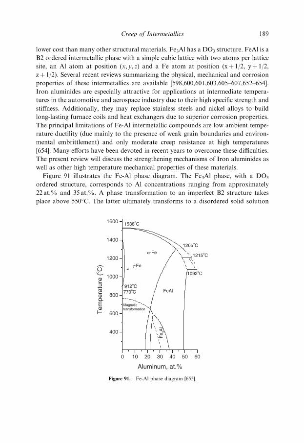
Figure 91 illustrates the Fe-Al phase diagram. The Fe3Al phase, with a DO3
ordered structure, corresponds to Al concentrations ranging from approximately
22 at.% and 35 at.%. A phase transformation to an imperfect B2 structure takes
place above 550�C. The latter ultimately transforms to a disordered solid solution
Figure 91. Fe-Al phase diagram [655].
Creep of Intermetallics 189

with increasing temperature. This, in turn, leads to the degradation of creep and
tensile resistance at high temperatures. The FeAl phase, which has a B2 lattice, is
formed when the amount of Al in the alloy is between 35 at.% and 50 at.%.
9.3.2 Anomalous Yield Point Phenomenon
An anomalous peak in the variation of the yield stress with temperature has been
observed in Fe-Al alloys with an Al concentration ranging from 25 at.% up to
45at.%. The peak appears usually at intermediate temperatures, between 400�C and
600�C [607,653–654,656–676]. This phenomenon is depicted in Figure 92 (from [661]),
which illustrates the dependence of the yield strength with temperature for several
large-grain Fe-Al alloys in tension at a strain rate of 10�4 s�1. Several mechanisms
have been proposed to rationalize the yield-strength peak but the origin of this
phenomenon is still not well understood. The different models are briefly described in
the following. More comprehensive reviews on this topic as well as critical analyses
of the validity of the different strengthening mechanisms are [653,656].
a. Transition from Superdislocations to Single Dislocations. Stoloff and Davies [662]
suggested that the stress peak was related to the loss of order that occurs in Fe3Al
alloys at intermediate temperatures (transition between the DO3 to the B2 structure).
According to their model, at temperatures below the peak, superdislocations
would lead to easy deformation, whereas single dislocations would, in turn, lead
to easy deformation at high temperatures. At intermediate temperatures, both
Figure 92. Variation of the yield strength with temperature for several large grain FeAl alloys strained in
tension at a strain rate of 10�4 s�1 (from [661]).
190 Fundamentals of Creep in Metals and Alloys
superdislocations and single dislocations would move sluggishly, giving rise to the
strengthening observed. It has been suggested, however, that this model cannot
explain the stress peak observed in FeAl alloys, where no disordering occurs at
intermediate temperatures and the B2 structure is retained over a large temperature
interval. Recently, Morris et al. also questioned the validity of this model [659]. They
observed that the stress peak occurred close to the disordering temperature at low
strain-rates in two Fe3Al alloys (Fe-28Al-5Cr-1Si-1Nb-2B and Fe-25Al, all atomic
percent). For high strain-rates the stress peak occurred at higher temperatures than
that corresponding to the transition. Thus, they concluded that the disordering
temperature being about equal to the peak stress temperature at low strain rates
was coincidental. Stein et al. [676] also did not find a correlation between these
temperatures in several binary, ternary and quaternary DO3-ordered Fe-26Al alloys.
b. Slip Plane Transitions f110g ! f112g. Umakoshi et al. [663] suggested that the
origin of the stress peak was the cross slip of h111i superdislocations from {110}
planes to {112} planes, where they become pinned. Experimental evidence supporting
this observation was also reported by Hanada et al. [664] and Schroer et al. [665].
Since cross slip is thermally activated, dislocation pinning would be more pronounced
with increasing temperatures, giving rise to an increase in the yield strength.
c. Decomposition of h111i Superdislocations: Climb Locking Mechanism. The yield
stress peak has often been associated with a change in the nature of dislocations
responsible for deformation, from h111i superdislocations (dislocations formed by
pairs of superpartial dislocations separated by an antiphase boundary) at low
temperatures, to h100i ordinary dislocations at temperatures above the stress peak
[666]. The h100i ordinary dislocations are sessile at temperatures below those
corresponding to the stress peak and thus may act as pinning points for h111i
superdislocations. The origin of the h100i dislocations has been attributed to the
combination of two a/2[111] superdislocations or to the decomposition of h111i
superdislocations on {110} planes into h110i and h100i segments on the same {110}
planes. As the temperature increases, decomposition may take place more easily, and
thus the amount of pinning points would increase leading to a stress peak. Experi-
mental evidence consistent with this mechanism has been reported by Morris and
Morris [667]. However, this mechanism was also later questioned by Morris et al.
[659], where detailed TEM microstructural analysis suggested that anomalous
strengthening is possible without the h111i to h100i transition in some Fe3Al alloys.
d. Pinning of h111i Superdislocations by APB Order Relaxation. An alternative
mechanism for the appearance of the anomalous yield stress peak is the loss of order
Creep of Intermetallics 191
within APBs of mobile h111i superdislocations with increasing temperature [668].
This order relaxation may consist of structural changes as well as variations in the
chemical composition. Thus, the trailing partial of the superdislocation would no
longer be able to restore perfect order. A frictional force would therefore be created
that will hinder superdislocation movement. With increasing temperature APB
relaxation would be more favored and thus increasing superdislocation pinning
would take place, leading to the observed stress peak.
e. Vacancy Hardening Mechanism. The concentration of vacancies in FeAl is in
general very high, and it increases in Al-rich alloys. Constitutional vacancies are
those required to maintain the B2 structure in Al-rich non-stoichiometric FeAl
alloys. Thermal vacancies are those excess vacancies generated during annealing at
high temperature and retained upon quenching. For example, the vacancy
concentration is 40 times larger at 800�C than that corresponding to a conventional
pure metal at the melting temperature. Constitutional vacancies may occupy up to
10% of the lattice sites (mainly located in the Fe sublattice) for Fe-Al compositions
with high Al content (>50%at.) [669]. The high vacancy concentration is due to the
low value of the formation enthalpy of a vacancy as well as to the high value of the
formation entropy (around 6 k) [670]. Vacancies have a substantial influence on the
mechanical properties of Iron aluminides [671].
It has been suggested that the anomalous stress peak is related to vacancy
hardening in FeAl intermetallics [672]. According to this model, with rising tempe-
ratures a larger number of vacancies are created. These defects pin superdislocation
movement and lead to an increase in yield strength. At temperatures higher than
those corresponding to the stress peak the concentration of thermal vacancies is
very large and vacancies are highly mobile. Thus, they may aid dislocation climb
processes instead of acting as pinning obstacles for dislocations [673] and softening
occurs.
The vacancy hardening model is consistent with many experimental observations.
Recently Morris et al. [658] reported additional evidence for this mechanism in a
Fe-40 at % Al alloy. First, they observed that some time is required at high tempe-
rature for strengthening to be achieved. This is consistent with the need of some time
at high temperature to create the equilibrium concentration of vacancies required for
hardening. Second, they noted that the stress peak is retained when the samples are
quenched and tested at room temperature. They concluded that the point defects
created after holding the specimen at high temperature for a given amount of time
are responsible for the strengthening, both at high and low temperatures.
Additionally, careful TEM examination suggested that vacancies were not present
in the form of clusters. The small dislocation curvature observed, instead, suggested
192 Fundamentals of Creep in Metals and Alloys

that single-vacancies were mostly present, which act as relatively weak obstacles to
dislocation motion.
The concentration of thermal vacancies increases with increasing Al content and
thus the effect of vacancy hardening would be substantially influenced by alloy
composition. Additionally, the vacancy hardening mechanism implies that the
hardening should be independent of the strain rate, since it only depends
on the amount of point defects present. In a recent investigation, Morris et al.
[659] analyzed the effect of strain rate on the flow stress of two Fe3Al alloys
with compositions Fe-28Al-5Cr-1Si-1Nb-2B and Fe-25Al-5Cr-1Si-1Nb-2B (at.%).
The variation of the flow stress with temperature and strain rate (ranging
from 4� 10�6 s�1 to 1 s�1) for the Fe-28 at.%Al alloy is illustrated in Fig. 93. It
can be observed that the ‘‘strengthening’’ part of the peak is rather insensitive to
strain rate, consistent with the predictions of the vacancy hardening model.
However, the investigators were skeptical regarding the effectiveness of this mecha-
nism in Fe3Al alloys, where the vacancy concentration is much lower than in FeAl
alloys and, moreover, where the vacancy mobility is higher. Highly mobile vacancies
are not as effective obstacles to dislocation motion. Another limitation of the
vacancy model is that it fails to explain the orientation dependence of the stress
anomaly as well as the tension-compression asymmetry in single crystals [657]. Thus,
the explanation of the yield stress peak remains uncertain. On the other hand, it
is evident in Fig. 93 that the softening part of the peak is indeed highly dependent
Figure 93. Variation of the yield stress with temperature and strain rate corresponding to the cast and
homogeneized Fe-28 at%Al alloy (from [659]).
Creep of Intermetallics 193

on strain rate. This is attributed to the onset of diffusional processes at high
temperatures, where creep models may be applied and rate dependence may be more
substantial [657,659].
9.3.3 Creep Mechanisms
The creep behavior of Iron aluminides is still not well understood despite the large
amount of creep data available on these materials [e.g. 654,677–689]. The values of
the stress exponents and activation energies corresponding to several creep studies
are summarized in Table 6 (based on [654] with added data). There are several
factors that complicate the formulation of a general creep behavior of Fe-Al alloys.
First, creep properties are significantly influenced by composition. Second, as
discussed in [600,690], both the stress exponent and the activation energy have been
observed to depend on temperature, in some cases. This suggests that several
mechanisms may control creep of Fe-Al and Fe3Al alloys. Other reasons may be the
frequent absence of genuine steady-state conditions as well as the simultaneous
occurrence of grain growth and discontinuous dynamic recrystallization. Never-
theless, in general terms, it can be inferred from Table 6 that diffusional creep or
Harper-Dorn creep may be the predominant deformation mechanism at very low
stresses and high temperatures. At intermediate temperatures and stresses, either
diffusion controlled dislocation climb or viscous drag have been suggested
[654,678,679,685].
a. Superplasticity in Iron Aluminides. Superplasticity has been observed in both
FeAl and Fe3Al with coarse grains ranging from 100 mm to 350 mm [691–695].
Elongations as high as 620% were achieved in a Fe-28 at%Al-2 at%Ti alloy
deformed at 850�C and at a strain rate of 1.26� 10�3 s�1. The corresponding n
value was equal to 2.5. Also, a maximum elongation of 297% was reported for a
Fe-36.5 at.%Al-2 at.%Ti alloy with an n value close to 3. Moreover, Lin et al. [695]
have reported an increasing number of boundaries misoriented between 3� and 6�
with deformation. They suggest that these could be formed as a consequence of
dislocation interaction, by a process of continuous recrystallization. The unusually
large starting grain sizes as well as the values of the stress exponents (close to 3)
would be consistent with a viscous drag deformation mechanism. However,
significant grain refinement has been observed during deformation [694–695]. The
correlation of grain refinement and large ductilities may, in turn, be indicative of the
occurrence of grain boundary sliding, to some extent. Grain boundary sliding is
favored when a large area fraction of grain boundaries is present and thus occurs
readily in fine-grained microstructures.
194 Fundamentals of Creep in Metals and Alloys
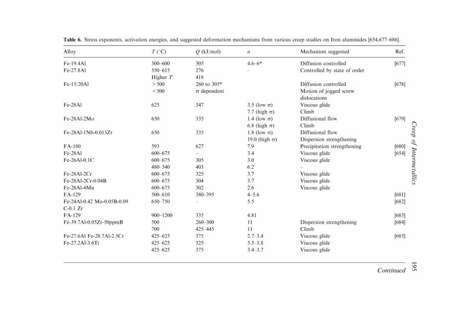
Table 6. Stress exponents, activation energies, and suggested deformation mechanisms from various creep studies on Iron aluminides [654,677–686].
Alloy T (�C) Q (kJ/mol) n Mechanism suggested Ref.
Fe-19.4Al 500–600 305 4.6–6* Diffusion controlled [677]
Fe-27.8Al 550–615
Higher T
276
418
– Controlled by state of order
Fe-15/20Al >500
<500
260 to 305*
s dependent
Diffusion controlled
Motion of jogged screw
dislocations
[678]
Fe-28Al 625 347 3.5 (low s)7.7 (high s)
Viscous glide
Climb
Fe-28Al-2Mo 650 335 1.4 (low s)6.8 (high s)
Diffusional flow
Climb
[679]
Fe-28Al-1Nb-0.013Zr 650 335 1.8 (low s)19.0 (high s)
Diffusional flow
Dispersion strengthening
FA-180 593 627 7.9 Precipitation strengthening [680]
Fe-28Al 600–675 – 3.4 Viscous glide [654]
Fe-26Al-0.1C 600–675
480–540
305
403
3.0
6.2
Viscous glide
–
Fe-28Al-2Cr 600–675 325 3.7 Viscous glide
Fe-28Al-2Cr-0.04B 600–675 304 3.7 Viscous glide
Fe-28Al-4Mn 600–675 302 2.6 Viscous glide
FA-129 500–610 380–395 4–5.6 [681]
Fe-24Al-0.42 Mo-0.05B-0.09
C-0.1 Zr
650–750 – 5.5 [682]
FA-129 900–1200 335 4.81 [683]
Fe-39.7Al-0.05Zr-50ppmB 500
700
260–300
425–445
11
11
Dispersion strengthening
Climb
[684]
Fe-27.6Al Fe-28.7Al-2.5Cr
Fe-27.2Al-3.6Ti
425–625
425–625
425–625
375
325
375
2.7–3.4
3.5–3.8
3.4–3.7
Viscous glide
Viscous glide
Viscous glide
[685]
Continued
Creep
ofInterm
etallics
195
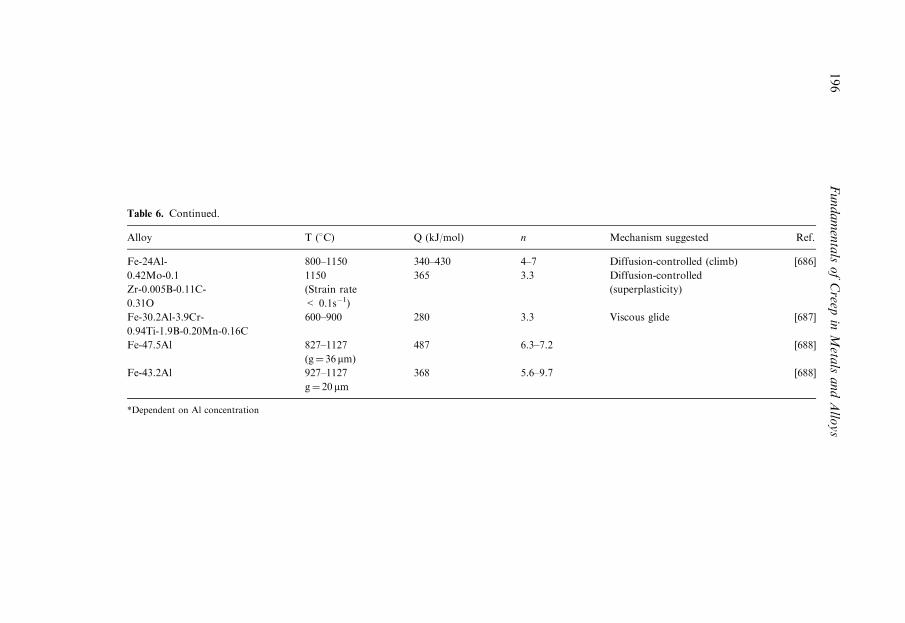
Table 6. Continued.
Alloy T (�C) Q (kJ/mol) n Mechanism suggested Ref.
Fe-24Al-
0.42Mo-0.1
Zr-0.005B-0.11C-
0.31O
800–1150
1150
(Strain rate
< 0.1s�1)
340–430
365
4–7
3.3
Diffusion-controlled (climb)
Diffusion-controlled
(superplasticity)
[686]
Fe-30.2Al-3.9Cr-
0.94Ti-1.9B-0.20Mn-0.16C
600–900 280 3.3 Viscous glide [687]
Fe-47.5Al 827–1127
(g¼ 36 mm)
487 6.3–7.2 [688]
Fe-43.2Al 927–1127
g¼ 20 mm368 5.6–9.7 [688]
*Dependent on Al concentration
196
FundamentalsofCreep
inMeta
lsandAllo
ys
9.3.4 Strengthening Mechanisms
The rather low creep strength of Iron aluminides is an area that has received
particular attention. Several strategies to increase the creep resistance have been
suggested, that are reviewed in [690]. One possibility is the reduction of the high
diffusion coefficient of the rate-controlling mechanism, which has been attempted by
micro- and macroalloying with limited success. Another way to achieve
strengthening is to add alloying elements that may hinder dislocation motion by
forming solute atmospheres around dislocations or by modifying lattice order. For
example, additions of Mn, Co, Ti and Cr moderately increase the creep resistance
due to solid solution strengthening. Finally, the most promising strengthening
mechanism seems to be the introduction of dispersions of second phases, such as
carbides, intermetallic particles or oxide dispersions. Dislocation movement is
hindered due to the attractive dislocation-particle interactions and thus the creep
rate may be reduced. A sufficient volume fraction of precipitate phases (around
1–3%) must be present in order for this mechanism to be effective and the precipi-
tates should be stable at the service temperatures. Alloying elements such as Zr, Hf,
Nb, Ta and B have been effective in improving creep resistance of FeAl by precipi-
tation hardening. Dispersoid particles also strengthen effectively Iron aluminides
[696–698].
Baligidad et al. [698–699] have reported that improved creep strength is obtained
in a Fe-16wt.%Al-0.5wt.%C possibly due to combined carbon solid-solution
strengthening and mechanical constraint from the Fe3AlC0.5 precipitates. They
claim that creep is recovery controlled and that climb assists the recovery. Morris-
Munoz [700] analyzed the creep mechanisms in an oxide-dispersion-strengthened
Fe-40 at.%Al intermetallic containing Y2O3 particles at 500�C and 700�C. The
absence of substructure formation at either temperature suggested, to the
investigators, constant-structure creep with a temperature-dependent threshold
stress. Particle-dislocation interactions were also apparent. It was concluded that the
threshold stress based on particle-dislocation interactions operates at 500�C
(where dislocations are predominantly h111i superdislocations) and that climb-
controlled processes occur at 700�C, where h100i dislocations are mainly present.
The decrease in creep resistance observed between 500�C and 700�C was attributed
to the rapid increase in diffusivity at high temperatures. Recently Sundar et al. [701]
reported creep resistance values for two Fe-40 at.%Al alloys (with additions of Mo,
Zr, and Ti for solute strengthening and additions of C and B for particle
strengthening) that were comparable to, if not better than, those of many
conventional Fe-based alloys. According to Sundar et al. [701], a combination of
strengthening mechanisms is perhaps the best way to improve creep resistance of
Iron aluminides.
Creep of Intermetallics 197

9.4 NICKEL ALUMINIDES
9.4.1 Ni3Al
The Ni-Al binary phase diagram is illustrated in Fig. 94. Ni3Al forms at Al
concentrations between 25 at.% and 27 at.%. This compound has a simple cubic
Bravais lattice with four atoms per lattice site: one Al atom, located in the (x, y, z)
position, and three Ni atoms, located, respectively, at the (xþ 1/2, y, z), (x, yþ 1/2, z),
and (x, y, zþ 1/2) positions. (This intermetallic received substantial attention since it
is the main strengthening phase in superalloys. Furthermore it has been considered to
be a technologically important structural intermetallic alloy system especially after its
successful ductilization by microalloying with boron [702]. Additionally, it exhibits a
flow stress anomaly, i.e., the yield stress increases with increasing temperature over
intermediate temperatures (230�C–530�C) as with Iron aluminides. Thus, it has often
been used as a model material for understanding intermetallic compounds in general.
Commercialization of Ni3Al for selected applications is underway [605,702].
The crystal structure of Ni3Al is an ordered L12 (f.c.c.) structure having Al atoms
at the unit cell corners and Ni atoms at the face centers. Similar to pure f.c.c. metals,
the planes of easy glide are the octahedral planes {111}. Slip along {001} planes is
Figure 94. Binary Ni-Al phase diagram [655].
198 Fundamentals of Creep in Metals and Alloys

more difficult, since they are less compact, but it may occur by thermal activation
[703]. Figure 95 illustrates an octahedral plane of this ordered structure. A perfect
dislocation associated with primary octahedral glide has a Burgers vector, b¼
a h110i, that is twice as large as that corresponding to a unit dislocation in the
disordered f.c.c. lattice, and is termed ‘‘superdislocation.’’ These dissociate into
‘‘super-partial’’ dislocations, with b¼ a/2 h110i, and the latter may, in turn, disso-
ciate into Shockley dislocations, with b¼ a/6 h112i, as depicted in Fig. 95.
The creep behavior of Ni3Al has drawn relatively little interest, perhaps due to
inadequate creep strength as compared to that of commercial nickel-based
superalloys and other intermetallic alloy systems such as NiAl and TiAl. The
creep behavior of Ni3Al will be briefly reviewed in the following.
a. Creep Curves. Creep tests have been performed on both single crystal [703–718]
and polycrystalline [715–717,719–733] Ni3Al alloys in tension and compression.
Figure 95. The octahedral {111} plane of the L12 crystal structure. The small circles are atoms one
plane out (above) of the page. Unit dislocations, b¼ ah110i, can dissociate into superpartial dislocations
with b¼ a/2h110i. The superpartials alter the neighboring lattice positions creating an antiphase
boundary (APB). Superpartials can dissociate into Shockley partial dislocations, with b¼ a/6h112i,
that are connected by a complex stacking fault (CSF) that includes both an APB and an ordinary
stacking fault [703].
Creep of Intermetallics 199

Most creep curves exhibit a normal shape, which consists of the conventional three
stages. However, some [e.g. 719–721] show Sigmoidal creep, where the creep-rate
decreases quickly to a minimum and this is followed by a continuous increase in the
creep-rate with strain. A steady state may or may not be achieved before reaching
tertiary creep after Sigmoidal creep. This creep behavior is also frequently termed
‘‘inverse creep’’ among the intermetallics community. Primary creep is often limited
to very small strains [612,708,718]. Figure 96 illustrates the creep curve of a Ni3Al
alloy (with 1 at.% Hf and 0.24 at.% B) deformed at 643�C at a constant stress of
745MPa [703]. Initially, the creep rate decreases with increasing strain and normal
primary creep occurs. This is followed by an extended region where the strain rate
continually increases with strain. Steady state may or may not be reached afterwards,
as will be explained later.
High-temperature creep refers to creep deformation at temperatures higher than
Tp, the temperature at which the peak yield stress is observed. This temperature
varies with alloy composition [732] and crystal orientation [704] but is typically
observed from 0.5 to 0.6Tm. Intermediate temperature creep usually refers to creep
deformation at temperatures lower than (but close to) Tp. A steady-state regime is
usually observed during high-temperature creep. The relationship between the strain
rate and the stress in the high-temperature range usually follows a power-
law relationship with a stress exponent of about 3. This may suggest that the
viscous glide of dislocations is the rate-controlling mechanism [600]. However, at
Figure 96. Sigmoidal creep curve corresponding to a Ni3Al alloy (with 1 at.%Hf and 0.24 at.%B)
deformed at 643�C at a constant stress of 745MPa [703]. Normal primary creep is followed by a
continuous increase in the strain rate. This creep behavior has been also termed ‘‘inverse creep’’.
200 Fundamentals of Creep in Metals and Alloys
intermediate temperatures, from about 0.3 Tm to 0.6 Tm, Sigmoidal creep may occur
depending on both the temperature and the stress [720,721]. Nicholls and Rawlings
[724] suggested that different creep mechanisms should operate below and above Tp.
b. Sigmoidal (or Inverse) Creep. Sigmoidal creep has been observed in both single-
and polycrystalline Ni3Al alloys [703,710,712,719–721], as well as in some other
intermetallics, e.g. Ni3Ga [735] and TiAl [721]. The onset of Sigmoidal creep (i.e., the
increase in the creep-rate after primary creep) usually takes place at very small
strains. This strain-rate increase may extend over a large strain interval, leading
directly to tertiary creep in the absence of a steady-state stage [703,710,719], as
illustrated in Fig. 96, or it may occur only for a small strain previous to the steady
state [705,720].
The conditions under which Sigmoidal creep occurs are relatively narrow. Rong
et al. [720] concluded that its occurrence depends on both temperature and stress.
It is generally accepted that Sigmoidal creep is more frequent and more pronounced
at intermediate temperatures [721]. Smallman et al. [721] suggested that sigmoidal
creep only occurs at temperatures below but very close to Tp and at stresses close
to the yield stress.
Hemker et al. [703] and, previously, Nicholls and Rawling [724], observed a
decrease of creep strength with increasing temperature in a single crystal alloy, with
composition Ni-22.18 at.%Al-1 at.%Hf-0.24 at.%B [703], in the temperature regime
where the yield strength is known to increase anomalously with temperature. This
observation led them to infer that different dislocation mechanisms would be
responsible for yielding (small strains) and for creep (large strains) and stimulated
a detailed investigation of the deformation mechanisms. It is now well established
that the yield stress anomaly in Ni3Al is due to the operation of octahedral slip of
h110i superdislocations that are retarded by cross-slip onto a cube plane at
temperatures below Tp [598]. Slip on cube planes is thermally activated and is not
favored at temperatures below Tp. However, superdislocations gliding on {111}
planes have a tendency to cross slip onto cube planes due to the presence of a torque
caused by their anisotropic elastic fields. When the screw segment of a super-
dislocation is cross slipped onto a cube plane its mobility decreases significantly and
this leads to an increase of the yield stress. Slip on cube planes becomes thermally
activated and takes place easily at temperatures higher than Tp, leading to a decrease
in the yield stress. Hemker et al. [703] proposed a model to explain the Sigmoidal
creep of Ni3Al based on careful microstructural examination. They suggested
that octahedral slip during primary creep is exhausted by the formation of Kear-
Wilsdorf (KW) locks, due to thermally activated cube cross-slip of the screw
segments. Thus the strain rate is progressively reduced until the cross-slipped
Creep of Intermetallics 201
segments become thermally activated and are able to bow out and glide on the cube
cross-slip plane. The KW locks act as Frank-Read type dislocation sources for glide
on the {001} cube planes. The dislocation generation and subsequent glide on the
cube planes leads to an increasing mobile dislocation density and thus to a larger
strain rate and Sigmoidal creep occurs. An alternative dislocation model for
Sigmoidal creep was proposed by Hazzledine and Schneibel [736]. They suggested
that two highly stressed octahedral slip systems which share a common cube cross-
slip plane, may interact ‘‘symbiotically’’ and unlock each other’s superdislocations
giving rise to an increasing number of h001i dislocations that are glissile on the
cube plane. Thus, Sigmoidal creep occurs.
Smallman et al. [721] pointed out that cube cross-slip is a necessary but not
sufficient condition for Sigmoidal creep. The operation of this mechanism, which
leads to a strain rate increase under some conditions, is compensated by the strain
rate decrease due to the exhaustion of dislocations on the octahedral slip systems. In
fact, Smallman et al. [721] observed cube cross-slip in a polycrystalline Ni3Al alloy
creep deformed at 380�C ðT � TpÞ, where Sigmoidal creep was not apparent.
Zhu et al. [704] also reported cube cross-slip in the absence of Sigmoidal creep in
single crystals of Ni3Al with different orientations. In order to rationalize these
observations, Rong et al. [720] suggested that Sigmoidal creep would occur only
when the length of a significant number of screw segments cross-slipped onto cube
planes from octahedral planes, as suggested by Hemker et al. [703], is larger than a
critical value. In this case, the density of mobile dislocations on the cube cross-slip
planes would increase significantly, leading to an increase in the creep-rate. Rong et
al. [720] also observed an anomalous temperature dependence of the creep strength
in a polycrystalline Ni3Al alloy, contrary to what Hemker et al. [703] had reported
for their single crystal alloy. Rong et al. [720] found this anomalous dependence
consistent with their TEM observations of a larger density of dislocations on cube
cross-slip planes at the lower temperatures. They suggested that the average length
of the screw segments on cube cross-slip planes would increase with decreasing
temperature. Thus, at low temperatures, there would be more dislocations with
lengths larger than the critical value or a higher mobile dislocation density and this
would lead to a lower creep resistance.
The occurrence of Sigmoidal creep has not only been found to depend on
temperature and stress, but also on the prior deformation and processing history.
For example, Sigmoidal creep disappears in a Ni3Al alloy prestrained 3% at ambient
temperature [719]. A recent investigation on a single crystal of Ni3Al(0.5%Ta)
indicated that the temperature of pre-creep deformation also affects the subsequent
creep behavior [714]. The implications of these observations in terms of the creep
mechanisms occurring have not been discussed.
202 Fundamentals of Creep in Metals and Alloys
c. Steady State Creep. In Ni3Al alloys, steady state creep can start very early and
extend over a considerable strain range (up to 20%) at high [708] as well as at inter-
mediate temperatures [704,718]. Occasionally this stage may be delayed or even absent
at intermediate temperatures if Sigmoidal creep occurs, as described above. As in
many other intermetallic systems, the minimum creep rate is used to calculate the
stress exponent and the activation energy for creep, using the well-established power-
law relations described elsewhere in this book, when clear steady state is not observed.
Table 7 summarizes some of the creep data obtained in various investigations on
Ni3Al-based alloys, mostly at high temperatures [706–711,715–718,722–725,
727–731,737–741]. This section will mainly focus on single phase alloys. The stress
exponent, n, ranges mostly between 3.2 and 4.4 in both single crystal and poly-
crystalline alloys. A lower value of about 1 was reported at low stresses in a
polycrystalline Ni3Al(Hf, B) [725,728]. A few studies have reported higher values of
6.7 [718], 8 [730] and 9 [742]. The values of the activation energy Qc for creep ranged
from 263 to 530 kJ/mol, but are generally between 320 and 380 kJ/mol. It is not
possible to normalize all the creep data of various Ni3Al alloys in a single plot, such
as in earlier chapters, due to the lack of diffusion coefficient and modulus of elasticity
values at various temperatures over the large variety of compositions investigated.
The rate-controlling mechanism during creep of Ni3Al intermetallics is still
unclear. Based on the analysis of the stress exponents, several studies suggested
dislocation glide (n� 3) [709–710,723,727,729], while others propose that dislocation
climb predominates (n� 4–5) [710,714,722,731], and yet others point toward Coble
or Nabarro-Herring creep (n¼ 1) [725,728]. However, others have questioned the
predominance of a single mechanism, since the stress exponents vary from 3 to 5.
Also, the Qc values have been found to be stress-dependent, in some cases [717], and
values are often much higher than the activation energy for diffusion (the activation
energy for diffusion of Ni in Ni3Al varies from 273 to 301 kJ/mol [743]). The
diffusivity of Al in NiAl is believed to be higher but it has still not been measured
directly due to the lack of suitable radioactive tracers [744].
Several TEM studies have been performed to investigate the microstructural
evolution of Ni3Al alloys during steady-state creep. In general, subgrains do not
readily form. Wolfenstine et al. [710] observed randomly distributed, curved,
dislocations in the n¼ 3 region between 810�C and 915�C, and a homogeneous
dislocation distribution with some evidence for subgrain formation in the n¼ 4.3
region (lower stresses) but no evidence for subgrain formation in the n¼ 3 region
(higher stresses) between 1015�C and 1115�C. Knobloch et al. [745] examined the
microstructure of [001], [011], and [111] oriented Ni3Al single crystals creep deformed
at 850�C at a stress of 350MPa. They observed an homogeneous dislocation
distribution for all orientations and creep stages. Stress exponents and activation
energies were not calculated. As mentioned above, the most common slip systems
Creep of Intermetallics 203
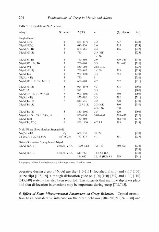
operative during creep of Ni3Al are the h110i{111} (octahedral slip) and h110i{100}
(cube slip) [107,149], although dislocation glide on h100i{100} [747] and h110i{110}
[745,748] systems has also been reported. This suggests that multiple slip takes place
and that dislocation interactions may be important during creep [708,745].
d. Effect of Some Microstructural Parameters on Creep Behavior. Crystal orienta-
tion has a considerable influence on the creep behavior [704–708,718,746–748] and
Table 7. Creep data of Ni3Al alloys.
Alloy Structure T (�C) n Qc (kJ/mol) Ref.
Single-Phase
Ni3Al(10Fe) P 871–1177 3.2 327 [723]
Ni3Al(11Fe) P 680–930 2.6 355 [724]
Ni3Al(Zr, B) P 860–965 4.4 406 [722]
Ni3Al(Hf, B) P 760 2-3 (HS)
1 (LS)
–
–
[725]
Ni3Al(Zr, B) P 760–860 2.9 339–346 [716]
Ni3Al(8Cr, Zr, B) P 760–860 3.3 391–400 [716]
Ni3Al(5V) P 850–950 2.89–3.37 – [727]
Ni3Al(Hf, B) P 760–867 1 (LS) 313 [728]
Ni3Al(Ta) P 950–1100 3.3 383 [729]
Ni3(Al, 4Ti) P 750 8 – [730]
Ni3Al(8Cr, Hf, Ta, Mo. . .) P 650–900 4.7 327 [731]
Ni3Al(Hf, B) S 924–1075 4.3 378 [708]
Ni-23.5Al S 982 3.5 – [707]
Ni3Al(Cr, Ta, Ti, W, Co) S 900–1000 3.5 380 [709]
Ni3(Al, 4Ti) S 852–902 3.3 282 [711]
Ni3Al(Ta, B) S 810–915 3.2 320 [710]
Ni3Al(Ta, B) 1015–1115 3.2 (HS)
4.3 (LS)
360
530
[710]
Ni3Al(Ta, B) S 850–1000 3.5 420 [706]
Ni3Al(X), X¼Ti, Hf, Cr, Si S 850–950 3.01–4.67 263–437 [715]
Ni3Al(4Cr) S 760–860 – 362–466 [717]
Ni3Al(Ti, 2Ta) S 850 1150 6.7 3.3 383
–
[718]
Multi-Phase (Precipitation Strengthed)
Ni3(Al, 4Ti) g/g0 650, 750 31, 22 – [730]
Ni-20.2Al-8.2Cr-2.44Fe g/g0–a(Cr) 777–877 4.1 301 [737]
Oxide-Dispersion Strengthened Ni3Al
Ni3Al(5Cr, B) 2 vol.% Y2O3 1000–1200 7.2, 7.8 650, 697 [738]
[739]
Ni3Al(5Cr, B) 2 vol.% Y2O3 649 732,
816 982
13.5 5.1 (LS)
22, 13 (HS) 9.1
–
239
[740]
[741]
P¼polycrystalline; S¼ single crystal; HS¼ high stress; LS¼ low stress.
204 Fundamentals of Creep in Metals and Alloys
this influence is highly dependent on temperature. At high temperatures, [001] is the
weakest orientation, showing the highest creep rate; [111] is the strongest orientation
associated with the lowest creep rate, about 1/5 to 1/2 of that of the [001] orientation.
Finally, the [011] and [123] orientations show an intermediate strength and the creep
rate is about 1/3 to 1/2 of the creep rate of the [001] orientation [705, 707–708,
718,745]. At intermediate temperatures, the [111] orientation is softer than the [001],
and the [123] has, again, an intermediate creep strength [704,708]. Thus, the
orientation dependence of creep strength at intermediate temperatures is opposite to
that at high temperatures. Models considering the operation of octahedral slip, cube
slip, and multiple slip have been proposed to explain and predict the creep
anisotropy at different temperatures [605,707,749]. However, it seems that the crystal
orientation has no obvious influence on the stress exponent n [706–707,718] and on
the activation energy Qc for creep [706,718].
Only a few studies on the influence of grain size on the creep of Ni3Al have been
published. Schneibel et al. [725] observed a grain size dependence of the creep rate of
a cast Ni3Al(Hf,B) alloy creep deformed at 760�C. They tested specimens with
average grain sizes of 12 mm, 50 mm, and 120 mm. Figure 97 illustrates the strain rate
vs. stress data from tests performed at high stresses in the samples with larger grain
sizes. The stress exponent is 3 for small grain sizes (50 mm) and significantly higher
for larger grain sizes (120 mm). The increase in the stress exponents is attributed to
scatter of the experimental data corresponding to the lowest strain rate. Thus, the
Figure 97. Stress dependence of the creep rate of Ni-23.5 at.%Al-0.5 at.% Hf-0.2 at.%B at high stresses
for two grain sizes (from [725]).
Creep of Intermetallics 205
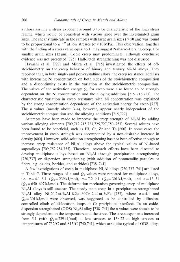
authors assume a stress exponent around 3 to be characteristic of the high stress
regime, which would be consistent with viscous glide over the investigated grain
sizes. The shear strain-rate in the samples with large grain sizes (>50 mm) was found
to be proportional to g�1.9 at low stresses (s<10MPa). This observation, together
with the finding of a stress value equal to 1, may suggest Nabarro-Herring creep. For
smaller grain sizes (12 mm), Coble creep may predominate, although conclusive
evidence was not presented [725]. Hall-Petch strengthening was not discussed.
Hayashi et al. [727] and Miura et al. [715] investigated the effects of off-
stoichiometry on the creep behavior of binary and ternary Ni3Al alloys. They
reported that, in both single- and polycrystalline alloys, the creep resistance increases
with increasing Ni concentration on both sides of the stoichiometric composition
and a discontinuity exists in the variation at the stoichiometric composition.
The values of the activation energy Qc for creep were also found to be strongly
dependent on the Ni concentration and the alloying additions [715–716,727]. The
characteristic variation in creep resistance with Ni concentration was explained
by the strong concentration dependence of the activation energy for creep [727].
The n values (mostly about 3–4), however, appear nearly independent of the
stoichiometric composition and the alloying additions [715,727].
Attempts have been made to improve the creep strength of Ni3Al by adding
various alloying elements [709,712,715,723,725,727,750–753]. Several solutes have
been found to be beneficial, such as Hf, Cr, Zr and Ta [600]. In some cases the
improvement in creep strength was accompanied by a non-desirable increase in
density [600]. However, solid-solution strengthening has not been effective enough to
increase creep resistance of Ni3Al alloys above the typical values of Ni-based
superalloys [709,752,754,755]. Therefore, research efforts have been directed to
develop multiphase alloys based on Ni3Al through precipitation strengthening
[730,737] or dispersion strengthening (with addition of nonmetallic particles or
fibers, e.g. oxides, borides, and carbides) [738–741].
A few investigations of creep in multiphase Ni3Al alloys [730,737–741] are listed
in Table 7. Three ranges of n and Qc values were reported for multiphase alloys,
i.e. n¼ 4.1–5.1 (Qc¼ 239 kJ/mol), n¼ 7.2–9.1 (Qc¼ 301 kJ/mol), and n¼ 13–31
(Qc¼ 650–697 kJ/mol). The deformation mechanism governing creep of multiphase
Ni3Al alloys is still unclear. The steady state creep in a precipitation strengthened
Ni3Al alloy Ni-20.2 at.%Al–8.2 at.%Cr–2.44 at.%Fe [737], where n¼ 4.1 and
Qc¼ 301 kJ/mol were observed, was suggested to be controlled by diffusion-
controlled climb of dislocation loops at Cr precipitate interfaces. In an oxide-
dispersion strengthened (ODS) Ni3Al alloy [738–741] the n values were shown to be
strongly dependent on the temperature and the stress. The stress exponents increased
from 5.1 (with Qc¼ 239 kJ/mol) at low stresses to 13�22 at high stresses at
temperatures of 732�C and 815�C [740,741], which are quite typical of ODS alloys
206 Fundamentals of Creep in Metals and Alloys

as discussed earlier. At higher temperatures (from 1000 to 1273�C) [738,739] the
stress exponents were 7.2 and 7.8 (with Qc¼ 650 and 697 kJ/mol, respectively). It was
suggested that the stress exponent of 5.1 in the ODS Ni3Al should not be considered
indicative of dislocation climb controlled creep as observed in pure metals and Class
M alloys and as proposed for some single phase Ni3Al alloys. Carreno et al. [738]
emphasized that both Arzt and co-workers’ Detachment model (described in the
chapter on second phase strengthening) and incorporating a threshold stress in any
model [605] are not appropriate approaches to describe the creep behavior of ODS
Ni3Al at higher temperatures. There is relatively poor agreement between the data
and the predictions by these models. Alternatively, they developed a ‘‘n-model’’
approach, which separates the contribution of the particles and that from the matrix.
They assume the measured stress exponent is equal to the sum of the stress exponent
corresponding to the matrix, termed hn, and an additional stress exponent, n, that is
necessary in order to account for the dislocation-particle interactions. The measured
activation energy can be obtained by multiplying the activation energy correspond-
ing to the matrix deformed under the same stress and temperature conditions by a
factor equal to (hnþ n/h). This approach satisfactorily models the data.
Figure 98 illustrates a comparison of the creep properties of an ODS Ni3Al alloy,
Ni-19 at.%Al-5 at.%Cr-0.1 at.%B with 2 vol.% of Y2O3 (filled circles) with a single
crystal Ni3Al alloy and two nickel-based superalloys, NASAIR 100 and MA6000.
Figure 98. Comparison of the creep behavior corresponding to an ODS Ni3Al alloy of composition Ni-
19 at.%Al-5 at.%Cr-0.1 at.%B with 2 vol.% of Y2O3 (g�400mm) [739] with a single crystal Ni3Al alloy
[708] and with the Ni superalloys NASAIR 100 [756], and MA6000 [757].
Creep of Intermetallics 207

Although the introduction of an oxide dispersion contributed to strengthening of the
Ni3Al alloy with respect to the single crystal alloy, the creep performance of ODS
Ni3Al was still poorer than that of commercial nickel-based superalloys.
9.4.2 NiAl
a. Introduction. NiAl is a B2 ordered intermetallic phase with a simple cubic lattice
with two atoms per lattice site, an Al atom at position (x, y, z) and a Ni atom at
position (xþ 1/2, yþ 1/2, zþ 1/2). This is a very stable structure that remains
ordered until nearly the melting temperature. As illustrated in the phase diagram of
Fig. 94, NiAl forms at Al concentrations ranging from 40 to about 55 at.%.
Excellent reviews of the physical and mechanical properties of NiAl are available in
[600,758,759].
NiAl alloys are attractive for many applications due to their favorable oxidation,
carburization and nitridation resistance, as well as their high thermal and electrical
conductivity. They are currently used to make electronic metallizations in advanced
semiconductor heterostructures, surface catalysts, and high current vacuum circuit
breakers [758]. Additionally, these alloys are attractive for aerospace structural
applications due to their low density (5.98 g/cm3) and high melting temperature [605].
However, two major limitations of single phase NiAl alloys are precluding their
application as structural materials, namely poor creep strength at high temperatures
and brittleness below about 400�C (brittle-ductile transition temperature). The
following sections of this chapter will review the deformation mechanisms during
creep of single-phase NiAl and the effects of different strengthening mechanisms.
b. Creep of Single-Phase NiAl. Most of the available creep data of NiAl were
obtained from compression tests at constant strain rate or constant load [760–780].
Only limited data from tensile tests are available [768,781]. It is generally accepted
that creep in single-phase NiAl is diffusion controlled. This has been inferred, first,
from the analysis of the stress exponents and activation energies. The values for these
parameters are listed in Table 8. In most cases, the stress exponents range from 4 to
7.5. Figure 99 illustrates the creep behavior of several binary NiAl alloys. Evidence
for the predominance of dislocation climb was also inferred from the values of the
activation energies which, in many investigations, are close to 291 kJ/mol, the value of
the activation energy for bulk diffusion of Ni in NiAl. Additionally, subgrain
formation during deformation has been observed [770], consistent with climb control.
However, occasionally stress exponents different from those mentioned above
have been reported. For example, values as low as 3 were measured in NiAl single
crystals by Forbes et al. [782] and Vanderwoort et al. [778], who suggested that both
208 Fundamentals of Creep in Metals and Alloys
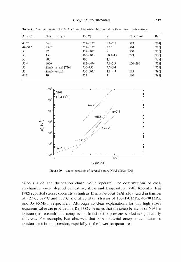
viscous glide and dislocation climb would operate. The contributions of each
mechanism would depend on texture, stress and temperature [778]. Recently, Raj
[782] reported stress exponents as high as 13 in a Ni-50 at.%Al alloy tested in tension
at 427�C, 627�C and 727�C and at constant stresses of 100–170MPa, 40–80MPa,
and 35–65MPa, respectively. Although no clear explanations for this high stress
exponent value are provided by Raj [782], he notes that the creep behavior of NiAl in
tension (his research) and compression (most of the previous works) is significantly
different. For example, Raj observed that NiAl material creeps much faster in
tension than in compression, especially at the lower temperatures.
Table 8. Creep parameters for NiAl (from [759] with additional data from recent publications).
Al, at.% Grain size, mm T (�C) n Q, kJ/mol Ref.
48.25 5–9 727–1127 6.0–7.5 313 [774]
44–50.6 15–20 727–1127 5.75 314 [775]
50 12 927–1027 6 350 [776]
50 450 800–1045 10.2–4.6 283 [770]
50 500 900 4.7 [777]
50.4 1000 802–1474 7.0–3.3 230–290 [778]
50 Single crystal [720] 750–950 7.7–5.4 [779]
50 Single crystal 750–1055 4.0–4.5 293 [780]
49.8 39 727 5 260 [781]
Figure 99. Creep behavior of several binary NiAl alloys [600].
Creep of Intermetallics 209

Diffusional creep has been suggested to occur in NiAl when tested at low stresses
(s<30MPa) and high temperatures (T>927�C) [783,784]. Stress exponents between
1 and 2 were reported under these conditions.
c. Strengthening Mechanisms. Several strengthening mechanisms have been utilized
in order to improve the creep strength of NiAl alloys. Solid solution of Fe, Nb, Ta,
Ti and Zr produced only limited strengthening. The presence of these solute atoms
caused the lowering of the stress exponent. Therefore the solute strengthening effects
are only significant at very high stresses [760,785]. Solute strengthening must be
combined with other strengthening mechanisms in order to obtain improved creep
strength. Precipitation hardening by additions of Nb, Ta or Ti renders NiAl more
creep resistant than solid solution strengthening (i.e., alloys with the same com-
position and same alloying elements in smaller quantities) but still significant
improvements are not achieved [761].
An alternative, more effective, strengthening method than solute or precipitation
strengthening is dispersion strengthening. Artz and Grahle [764] mechanically
alloyed dispersed particles in a NiAl matrix and obtained favorable creep strength
up to 1427�C. Figure 100 (from [764]) compares the creep strengths of an ODS
NiAl-Y2O3 alloy with a ferritic Superalloy (MA956) and a precipitation strengthened
NiAl alloy in which the composition of the precipitates is AlN at 1200�C. The ODS
Ni alloy is more creep resistant than the Ni Superalloy MA956 at these high
Figure 100. Comparison of the creep behavior of a coarse-grained (g¼ 100mm) ODS NiAl alloy [764]
with the ferritic ODS Superalloy MA956 and with a precipitation strengthened NiAl-AlN alloy produced
by cryomilling [767].
210 Fundamentals of Creep in Metals and Alloys

temperatures. The ODS NiAl alloy is also more resistant than the precipitation
strengthened alloy at low strain rates. Artz and Grahle [764] also observed that the
creep behavior of ODS NiAl is significantly influenced by the grain size. In a coarse
grain size (g¼ 100 mm) ODS NiAl-Y2O3 alloy, the creep behavior showed the usual
characteristics of dispersion strengthened systems, i.e., high stress exponents (n¼ 17)
and activation energies much higher than that of lattice self-diffusion (Q¼ 576 kJ/
mol). However, intermediate stress exponents of 5 and very high activation energies
(Q¼ 659 kJ/mol) were measured in an ODS NiAl-Y2O3 alloy with a grain size of
0.9 mm. This creep data could not be easily modeled using established relationships
for diffusional or for detachment-controlled dislocation creep [764]. Arzt and Grahle
[764] suggest that the presence of particles at grain boundaries partially suppresses
the sink/source action of grain boundaries by pinning the grain boundary
dislocations and, thus, hinders Coble creep. However, the low stress exponent
indicates that Coble creep is not completely suppressed. Arzt and Grahle [764]
proposed a phenomenological model based on the coupling between Coble creep and
the grain boundary dislocation-dispersoid interaction (controlled by thermally
activated dislocation detachment from the particles, as indicated in an earlier
chapter). The predictions of this model agree satisfactorily with the experimental
data. HfC and HfB2 can also provide significant particle strengthening [760].
Matrix reinforcement by larger particles such as TiB2 and Al2O3 or whiskers also
increases significantly the strength of NiAl alloys [760,765,786]. Xu and Arsenault
[765] investigated the creep mechanisms of NiAl matrix composites with 20 vol.% of
TiB2 particles of 5 and 150 mm diameter, with 20 vol.% of Al2O3 particles of 5 and
75 mm diameter, and with 20 vol.% of Al2O3 whiskers. They measured stress
exponents ranging from 7.6 to 8.4 and activation energies similar to that of lattice
diffusion of Ni in NiAl. They concluded that the deformation mechanism is the same
in unreinforced and reinforced materials, i.e., dislocation climb is rate-controlling in
NiAl matrix composites during deformation at high temperature. Additionally,
TEM examination revealed long screw dislocations with superjogs. Xu and
Arsenault [765] suggested, based on computer simulation, that the jogged screw
dislocation model, described previously in this book, can account for the creep
behavior of NiAl metal matrix composites.
Creep of Intermetallics 211