chem1116 transfer procedure.pdf
TRANSCRIPT

7/27/2019 CHEM1116 TRANSFER PROCEDURE.PDF
http://slidepdf.com/reader/full/chem1116-transfer-procedurepdf 1/21
TANK BARGE CARGO TRANSFER
PROCEDURES
TANK BARGE
CHEM1116
CARGO TRANSFER PROCEDURES
As required by 33 CFR 155.750(a)
Operator:
American Commercial Lines, LLC
P.O. Box 610 Jeffersonville, Indiana 47131
(888) 709-5124
REPORT ALL SPILLS TO:
U.S. Coast Guard National Response Center
(800) 424-8802

7/27/2019 CHEM1116 TRANSFER PROCEDURE.PDF
http://slidepdf.com/reader/full/chem1116-transfer-procedurepdf 2/21
Home Port: JEFFERSONVILLE, IN
Barge Name: CHEM1116 (ex NMS 1465)
Official Number: 577458
Hull Number: St. Louis Ship 3790
Year Built 1977
Gross Tons: 847
Displacement Tons: 315
Length (Molded): 195’
Breadth (Molded): 35’-00"
Depth (Molded, Deck at Side): 12'-00"
Cargo Tank Capacity (100%): 10,620 Barrels
7/27/2019 CHEM1116 TRANSFER PROCEDURE.PDF
http://slidepdf.com/reader/full/chem1116-transfer-procedurepdf 3/21
155.750(a) (1) PRODUCTS TO BE TRANSFERRED:
A. The products carried by each barge are listed on the Certificate of Inspection. The Certificate of
Inspection is available on the barge and a copy of each Certificate is available from the ACL office.
B. For loading operations consult loading plans or other instructions issued by the shore facility operator to
determine the names of the petroleum or chemicals to be loaded. Before beginning transfer operations, obtain
information on safety, fire and personnel protection from cargo information cards and Material Safety Data
Sheets (MSDS) received from shore facility personnel. The information must be in written form and on board
the vessel. Only products authorized by the Certificate Of Inspection may be loaded.
C. For Unloading Operations consult the barge cargo manifest and / or shipping papers for the names of the
petroleum or chemicals to be unloaded. For hazard and reactivity data see the Cargo Information Card and / or the
MSDS.
D. These procedures do not apply to split loading. Contact the Barge Maintenance office in
Jeffersonville (812 288-0100) for specific instructions if this barge is supposed to receive a split load.
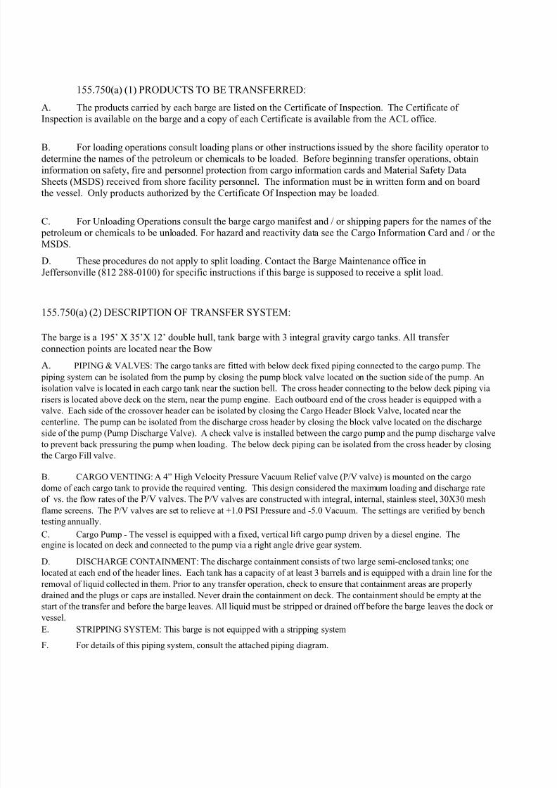
155.750(a) (2) DESCRIPTION OF TRANSFER SYSTEM:
The barge is a 195’ X 35’X 12’ double hull, tank barge with 3 integral gravity cargo tanks. All transfer
connection points are located near the Bow
A. PIPING & VALVES: The cargo tanks are fitted with below deck fixed piping connected to the cargo pump. The
piping system can be isolated from the pump by closing the pump block valve located on the suction side of the pump. An
isolation valve is located in each cargo tank near the suction bell. The cross header connecting to the below deck piping via
risers is located above deck on the stern, near the pump engine. Each outboard end of the cross header is equipped with a
valve. Each side of the crossover header can be isolated by closing the Cargo Header Block Valve, located near thecenterline. The pump can be isolated from the discharge cross header by closing the block valve located on the discharge
side of the pump (Pump Discharge Valve). A check valve is installed between the cargo pump and the pump discharge valve
to prevent back pressuring the pump when loading. The below deck piping can be isolated from the cross header by closing
the Cargo Fill valve.
B. CARGO VENTING: A 4” High Velocity Pressure Vacuum Relief valve (P/V valve) is mounted on the cargo
dome of each cargo tank to provide the required venting. This design considered the maximum loading and discharge rate
of vs. the flow rates of the P/V valves. The P/V valves are constructed with integral, internal, stainless steel, 30X30 mesh
flame screens. The P/V valves are set to relieve at +1.0 PSI Pressure and -5.0 Vacuum. The settings are verified by bench
testing annually.
C. Cargo Pump - The vessel is equipped with a fixed, vertical lift cargo pump driven by a diesel engine. The
engine is located on deck and connected to the pump via a right angle drive gear system.
D. DISCHARGE CONTAINMENT: The discharge containment consists of two large semi-enclosed tanks; one
located at each end of the header lines. Each tank has a capacity of at least 3 barrels and is equipped with a drain line for the
removal of liquid collected in them. Prior to any transfer operation, check to ensure that containment areas are properly
drained and the plugs or caps are installed. Never drain the containment on deck. The containment should be empty at the
start of the transfer and before the barge leaves. All liquid must be stripped or drained off before the barge leaves the dock or
vessel.
E. STRIPPING SYSTEM: This barge is not equipped with a stripping system
F. For details of this piping system, consult the attached piping diagram.

7/27/2019 CHEM1116 TRANSFER PROCEDURE.PDF
http://slidepdf.com/reader/full/chem1116-transfer-procedurepdf 4/21

7/27/2019 CHEM1116 TRANSFER PROCEDURE.PDF
http://slidepdf.com/reader/full/chem1116-transfer-procedurepdf 5/21
155.750 (3) PERSONS REQUIRED:
At least two qualified persons are required for cargo transfer; One person on the barge and one person on the
dock. The person on the barge shall be the person in charge of the transfer. The person in charge of the
transfer shall have a tankerman's document issued by the U.S. Coast Guard which is endorsed for the grade of
the cargo being transferred. However, when the terminal at which the barge is being loaded has received specific approval from the U.S. Coast Guard to do so, two barges may be loaded simultaneously with one person in charge for both barges.
Special Requirements: Only the Person-In-Charge is to be on the barge at any time during thetransfer of these products: formic acid, amines, acrylonitrile, adiponitrile, acetonitrile, or aniline.
155.730 (4) DUTIES OF THE PERSON IN CHARGE:
A. Prior To Transfer:
1. Check all barge moorings to ensure that they are properly secured and in satisfactory condition.
Reference section 155.750(a)(5) as to number and size.2. Examine deck and hull. Open and look into all void spaces to ascertain that there are noabnormal conditions that could affect the safe transfer of the cargo. All man way hatches are tobe secured upon completion of this examination.
3. Check U.S. Coast Guard Certificate of Inspection and Certificate of Financial Responsibility toensure they are on board, are valid and have the product being transferred endorsed.
4. Examine the Cargo Information Card or MSDS to obtain information concerning cargo hazards,reactivity and safety and whether or not this cargo requires vapor control.
5. Confirm with the facility Person in Charge on whether or not a sample is to be drawn. If needed, the sample will be drawn at the ship or barge tanks prior to cargo entering a tank. If thesample is approved by the customer’s surveyor the cargo transfer can commence, if not thenthe cargo is to be slopped until a good sample is received and approved.
6. Review static electricity precautions and the initial transfer rate found at the end of theseprocedures.
7. Visually inspect cargo piping and containment systems for cleanliness, remaining cargo andabnormal conditions. PIC must not break seals (if installed) without approval of thefacility/shipper and must wear appropriate PPE.
8. Place on board two, approved type, B-II portable fire extinguishers.9. Connect cargo hoses or loading arms from dock to appropriate header on the stern of the
barge. Use a full set of flange bolts and the proper size gasket for each connection. Theconnections must be securely bolted with a bolt in every hole.
10. Check the valve on the opposite (unused) side of the headers to ensure that they are closedand that a blind is secured on the flange using a full set of bolts.
11. Check the operation of the P/V valve.12. Check the grounding cable (if used) to ensure that it is properly connected or that an isolating
flange has been properly installed

7/27/2019 CHEM1116 TRANSFER PROCEDURE.PDF
http://slidepdf.com/reader/full/chem1116-transfer-procedurepdf 6/21
DUTIES OF THE PERSON IN CHARGE: (continued)
13. Establish a means for continuous communications with the Person in Charge at the facility.The method selected must be effective during all phases of the transfer.
14. Consult with the Facility Person in Charge concerning details of the transfer and ensure thateach person in charge understands the following details of the transfer operation:
(1) The identity of the product to be transferred and approximate amount to be transferred
(2) The sequence of transfer operations;
(3) The transfer rate;
(4) The name or title and location of each person participating in the transfer operation;
(5) Details of the transferring and receiving systems;
(6) Critical stages of the transfer operation;
(7) Federal, state, and local rules that apply to the transfer of oil or hazardous material;
(8) Emergency procedures;
(9) Discharge containment procedures;(10) Discharge reporting procedures;
(11) Watch or shift arrangement;
(12) Transfer shutdown procedures;
15. Complete and sign the "Declaration of Inspection".
16. Open the cargo control valves at the cargo tanks.
17. Ensure a proper flame screen is in place on all tank openings.
18. Uncap the stick gauges and engage the stick gauge magnet with the float magnet.
19. Inform the facility Person in Charge that the barge is ready for transfer.
20. When the facility Person in Charge informs you that the facility is ready for transfer, open thecargo control valves on the headers.
21. Confirm cargo is transferring to the proper cargo tanks.
B. During Transfer:
1) Check mooring lines frequently, at intervals of not more than 30 minutes and adjust asnecessary. In conditions where the barge is surging due to passing vessels or high winds,additional mooring lines will be used to ensure a secure mooring. 2) Monitor cargo levels in thetank by observing the ladder rungs and stick gauges at the gauging tubes. Make sure to inspect
wing voids for any water accumulation during the loading process. 3) No cargo transfer operations will be conducted when electrical or thunderstorms are in the vicinity. 4) Constantlymonitor cargo transfer operation to guard against an accidental discharge of oil. Minimize thenumber of tank openings to prevent contamination of cargo containment spaces.

7/27/2019 CHEM1116 TRANSFER PROCEDURE.PDF
http://slidepdf.com/reader/full/chem1116-transfer-procedurepdf 7/21
155.750(a) (5) TENDING OF MOORING LINES
Upon boarding the barge, whether at anchorage or at a terminal, it shall be the responsibility of thePerson-in-Charge to check the mooring lines to see that they are in good condition, adequate innumber and properly secured. Present and expected conditions of wind, weather, tide, and draft
changes due to cargo loading shall be taken into account when checking mooring lines. PIC shallmeet all facility mooring requirements of number and size of lines before transferring cargo.
Promptly report any frayed or broken mooring lines so that they may be replaced. When shift boats
other than ACBL boats are used, be sure that they place sufficient lines on the barge before dismissing
the shift boat. If for any reason the shift boat refuses to leave sufficient lines, notify the dispatcher
immediately.
155.750(a) (6) EMERGENCY SHUTDOWN AND COMMUNICATIONS
Emergency Shut Down:
This vessel is equipped with a pump driven by a diesel engine. In the event of an emergency duringunloading operations, the flow of cargo may be stopped by pulling the remote shut down cable locatednear the center of the barge and marked with a sign. The tankerman must verify the shut downoperates before each transfer.
The tankerman shall discuss emergency shutdown procedures with the vessel or facility prior to thetransfer of cargo. This discussion should include:
1) Circumstances requiring the transfer to stop immediately,
2) Primary and secondary means of communication,
3) Valves to be closed, location of the shutdown cable, and other actions to be taken in the event of an emergency,
4) How long it will take for the shutdown to take effect (is it immediate or does it take severalminutes in order to avoid rupturing lines)
Communications:
Communications shall be established, between the terminal (or vessel) and the barge before the
transfer hoses are hooked up. Communications must be maintained until the transfer is complete and
hoses are disconnected. PIC must routinely check communication at least every 2 hours. If portable
radio devices are used, they must be intrinsically safe and meet the requirements of 46 CFR § 110.15-
100(I) Class I, Division I, Group D as defined in 46 CFR § 111.80
If at any time during transfer operations communications are interrupted, STOP ALL
TRANSFER OPERATIONS and do not resume until communications have been re-
established.

7/27/2019 CHEM1116 TRANSFER PROCEDURE.PDF
http://slidepdf.com/reader/full/chem1116-transfer-procedurepdf 8/21
C. 155.750(a) (7) PROCEDURES FOR TOPPING OFF TANKS
1. Person in Charge (PIC) of the loading will determine cargo compartment(s) and sequences tobe used during the topping off procedures. The PIC must consider such factors as cargocompartment size, outage space, cargo amount to be topped off, vessel trim, vessel draft, cargocompartment openings before selecting the cargo compartment to be topped off. The topping
off procedure must be done without spillage of any cargo outside the cargo compartment whilemaintaining proper vessel trim/draft.
2. Definite agreement with the shore personnel concerning the rate of flow for topping off and finalshut down must be reached prior to the topping off operation.
3. When cargo tanks are nearing the desired loading, regulate the cargo rate using the cargocontrol valves at each tank. Advise the Facility Person In Charge (F-PIC) approximately 1 hour,30 minutes, 15 minutes, and 5 minutes prior to competing top off
4. Do not load the tanks so as to exceed the loading restrictions on the Certificate Of Inspection. Adequate room to permit expansion of the product should remain in each tank. In no caseshould a tank be loaded above 6” from the deck (ullage) at the gauge point.
5. As each tank is topped off, the compartment and associated block valves should be closed.6. When topping off is complete, close the header valves.
7. After the transfer is complete, gently push the sticks on the gauges back into their tubes andreplace the cap
D. 155.750(a) (8) PROCEDURES FOR ENSURING VALVES ARE CLOSED
1. Close and dog down all cargo hatch covers, ullage opening covers and gauge tube plugs.
2. Check all cargo control valves to ensure they are tightly closed.
3. Disconnect cargo hoses or loading arms from the headers and secure the ends with asuitable blind flange, gasket and full set of bolts.
155.750(a) (9) PROCEDURES FOR REPORTING DISCHARGES OR OIL OR HAZARDOUSMATERIAL
In the event of any irregularities, perceived unsafe conditions or emergencies on board this
barge prior to, during or after cargo transfer operations, immediate notice must be given to
American Commercial Lines, LLC, P.O. Box 610, Jeffersonville, Indiana 47131.(877) 857-1225
In the event of a cargo spill into the water immediately notify:
1. The receiving vessel or facility to stop the transfer.
2. U.S. Coast Guard National Response Center (800) 424-8802
3. The American Commercial Lines, Inc. Qualified Individual: (800) 709-5124
Use the Emergency Notification Checklist (Appendix B of the Vessel Response Plan) to assist youwith the notifications. It is located with the COI in the barge mailbox.

7/27/2019 CHEM1116 TRANSFER PROCEDURE.PDF
http://slidepdf.com/reader/full/chem1116-transfer-procedurepdf 9/21
155.750(a) (10) PROCEDURES FOR CLOSING AND OPENING VESSEL OPENINGS
Only the Person-in-Charge of the transfer, or a person designated by the Person-in-Charge, may open
or close any vessel opening that maintains the seaworthy condition of the tank vessel and prevents the
inadvertent release of cargo in the event of an accident. All vessel openings must be closed after the
cargo transfer is complete.
155.750(a) (11) TRANSFER HOSES
If an oil or hazardous material transfer hose is used it must be marked with the test date and name of
the product which it can be used for. If it is not specifically marked, then before it is hooked up the
tankerman must verify the test date and compatible products which can be transferred through the
hose. This is done by comparing the hose identification with a list of compatible products provided by
the supplier of the hose. These documents may be found in the mailbox on the barge or the Pilot
House of the attending boat. Hoses are to be tested annually in accordance with 33 CFR 156.170.
STATIC ELECTRICITY PRECAUTIONS
Precautions against static electricity may be necessary when the cargo being transferred is known asan accumulator of static electricity. Clean oils (distillates) are generally accumulators of staticelectricity. They require precautions at the beginning of transfers. These oils are: natural gasoline,kerosene, white spirits, motor and aviation gasoline, jet fuels, clean diesel oils, heating oils, heavy gasoils, naphtha, and lubricating oils. When any of these products are being transferred these proceduresshall be followed:
1 At the beginning of cargo flow into EACH cargo tank the flow rate should not exceed 730bbls/hr:2 After you determine that there is no more splashing and surface turbulence in a cargo tankthe flow rate can be increased to the maximum allowable transfer rate.3 During - and for 30 minutes after completing the loading - ullage and sampling equipmentmust not be put into the tank. Ropes or lines used to lower equipment into the cargo tank must beonly NATURAL fiber-cotton, sisal, hemp or flax. Synthetic line such as nylon or something similar must NEVER be used.4 Operations performed through restricted gauging tubes are permissible at any time duringtransfer unless not allowed by vapor emission restrictions.5 If the cargo tank atmosphere is maintained inert no anti-static precautions are necessary.

7/27/2019 CHEM1116 TRANSFER PROCEDURE.PDF
http://slidepdf.com/reader/full/chem1116-transfer-procedurepdf 10/21
SPECIAL OPERATIONS - Transferring Between Two Barges and a Facility Using One PIC
If an approved Letter of Alternate Compliance (LOAC) from the local Coast Guard Captain of the Port
is attached to these procedures (it should be in the barge mail box), then one (1) person may serve as
Person-in-Charge of transfer operations between two barges and a facility if the following procedures
are followed.
The following additional procedures will apply:
1. Read the LOAC and verify the following information:
Is the letter still valid? Is the product covered (some apply only to oil) Is the transfer operation covered (some apply only to discharges) Is the facility approved for a one tankerman-two barge transfer? Are there any special requirements in the letter, for example a four hour notice?
Are there any special requirements for topping off or stripping: May the tankermantop off or strip the outboard barge while discharging or loading the inboard barge?
1. Comply with standard oil transfer procedures.2. Ensure that the tankerman can easily and rapidly get from one barge to the other in the event
of an emergency.3. Use a minimum of six (6)-mooring lines with fenders between the barges to absorb any shock
in case the barges slam together. At least three mooring lines should be led forward and threeled aft. The mooring lines must be examined frequently during transfer operations and tendedaccordingly.
4. There shall be no sharp bends in the crossover hose that would cause undue strain on theconnecting flanges.
5. Where possible, the crossover hose should be supported by a boom or davit.6. The hose must never rest on a drip pan edge.7. The smaller of the two barges should be the outboard barge8. Transfer product first from the outboard barge.

7/27/2019 CHEM1116 TRANSFER PROCEDURE.PDF
http://slidepdf.com/reader/full/chem1116-transfer-procedurepdf 11/21
SPECIAL OPERATIONS - Benzene Requirements
(and cargo mixtures containing benzene such as: prolysis gasoline, gasoline, cracked naphtha andhardcut reformate)
Federal Regulations (46 CFR 151.50-60) concerning benzene require that the licensed officer, certified
tankerman or Person-in-Charge of a barge ensure no person on the barge is exposed to an airborneconcentration of benzene in excess of one part per million (1 PPM) as an eight hour time weighted average(TWA) or five parts per million (5 PPM) TWA over any 15 minute period. Since these limits may be exceededduring barge loading, it is ACBL's requirement that the following precautions be taken while sampling cargo,connecting or disconnecting a hose, opening a cargo tank, butterworth hatch, ullage opening, sounding tube or any other opening if the product contains more than 0.5% (1/2 of 1%) benzene.
1 Respirators meeting 29 CFR 1910.134 must be worn. See the specific requirements for the particular operation involved. Cartridges must be changed every eight hours, at the end of a shift, when the wearer experiences “break through”, or if they become difficult to breathe with - whichever comes first.2 Connections, disconnections, or any other operation with the possibility of a splash hazard ust bedone only by personnel with at least a half- mask respirator, “splash suit” or slicker jacket, rubber gloves,rubber boots and goggles or face shield (unless a full face respirator is used). In addition, if the productcontains 50% or more Benzene, the tankerman should wear a slicker suit.
3 Post a sign stating:
BENZENE CANCER HAZARD IN THIS AREA
PROTECTIVE EQUIPMENT MAY BE REQUIRED
AUTHORIZED PERSONNEL ONLY
1 Observe safe work practices by remaining upwind of the tanks, pumps, and piping systemwhenever possible. Use commonsense to minimize exposure.2 Restrict visitor access during the transfer.
LOADING: When loading products containing more than 5% benzene a half-mask is to be worn during the entireoperation. These products are normally loaded using vapor recovery equipment. If the MSDS indicates theproduct contains 5% or more benzene and the customer does not require vapor recovery loading, the tankerman
shall load the barge closed hatch. All tanks will be vented through the gooseneck vent located on the bow.DISCHARGING: When discharging products containing more than 5% benzene a half-mask is to be worn duringthe entire operation. Products containing more than 5% benzene will normally be discharged closed hatch and alltanks will be vented through the gooseneck vent located on the forward end of the barge. Final stripping of thebarge may be performed open hatch, using the installed stripping system, while the tankerman wears theappropriate personal protective equipment with at least a full face respirator. Products containing more than 50%Benzene will be discharged closed hatch. All tanks will be vented through the gooseneck vent located on theforward end of the barge. Final stripping of the barge may be performed open hatch, using the installedstripping system. However, the tankerman performing the stripping must wear a full-face respirator.
STRIPPING OVER THE TOP: Products containing less than 50% Benzene may be stripped over the top. Inorder to perform this operation, the tankerman must wear a full-face respirator, slicker suit, rubber gloves andrubber boots. This operation must not be performed underway. The barge must be put into a bank, dock or mooring with the boat tied alongside, upwind from the barge.
Barges containing more than 50% benzene, or with possible concentrations of more than 50% benzene, will notbe stripped over the top underway. This operation may be performed at a shore side facility if the tankermanwears a supplied air respirator, rubber gloves, rubber boots and slicker suit.
Further detail on benzene cargo handling is available in ACL's Benzene Program.

7/27/2019 CHEM1116 TRANSFER PROCEDURE.PDF
http://slidepdf.com/reader/full/chem1116-transfer-procedurepdf 12/21
SPECIAL OPERATIONS - Hydrogen Sulfide (H2S)
Certain products loaded on ACBL barge may contain hydrogen sulfide, this can most easily be
determined when checking the Material Safety Data Sheet during the initial pre-transfer conference. If
the tankerman thinks that H2S may be present the following procedures will be followed:
1. Carry a half mask respirator and Hydrogen Sulfide monitor on your person, the monitor isset for 10 PPM.. The monitor must be worn on the front of your body within one foot of your face, this area is called the “breathing zone.” Do not place the monitor inside cargo hatchesor lower it into tanks. If you do you may burn out the sensor and not get an accuratereading later on.
2. While preparing to commence the transfer take note of wind speed and direction. Duringthe transfer you must be aware of any change, such as a passing vessel blocking the wind.
3. Look for escape routes beforehand. Identify the safe routes that you will follow to getaccess to the dock or adjoining vessels. If in an escape situation go crosswind from thesource of the H2S exposure.
4. Make sure that the monitor is in place and turned on throughout the transfer, continuouslycheck it.
5. Observe safe work practices by remaining upwind of the tanks, pumps, and piping systemwhenever possible. Use commonsense to minimize exposure.
6. Restrict visitor access during the transfer.7. Because H2S is flammable all ignition sources must be eliminated and No Smoking Rules
strictly observed.8. If the monitor alarm goes off immediately put on your mask and move crosswind until out of
the H2S. Remember, that H2S can kill your sense of smell. In a safe area (one without(H2S) clear the alarm - this should happen automatically as the H2S level drops - thencarefully return to the barge watching the readings as you proceed. If the level rises to or remains at 10 ppm or above a second time STOP THE TRANSFER AND CALL FOR A
SHORE TANKERMAN. The air purifying respirators are approved for ESCAPE ONLY.

7/27/2019 CHEM1116 TRANSFER PROCEDURE.PDF
http://slidepdf.com/reader/full/chem1116-transfer-procedurepdf 13/21
SPECIAL OPERATIONS - Ethylene Dichloride (EDC)
Ethylene Dichloride (EDC) will be loaded using the Vapor Recovery System. Nitrogen is used to
minimize the amount of moisture that comes in contact with cargo. As an added benefit, it reduces the
amount of cargo vapors to a minimum. In addition to this precaution and normal cargo loadingprocedures, the measures listed below will also be taken:
1. Empty tanks will be purged with Nitrogen after every discharge.
2. Once the tanks are loaded, a nitrogen pad will be added on top of the cargo.
3. All hose connections and disconnections will be performed by a tankerman wearing the followingpersonal protective equipment:
. Respirator (provided) . Chemical resistant gloves (provided) . Rain slicker . Rubber boots
.
4. 4. Cargo hoses will be blown back to the barges using nitrogen.
5. Since EDC is heavier than water, barges will be loaded to a maximum draft of 10' 6" and tankswill not be full.
6. 6. Wood covers will be provided for drip pans. Pans will be kept covered when not loadingcargo.
7. Drip pans will be stripped to the slop tanks only when necessary. When stripping, tankermenmust wear the protective equipment listed above.
8. The dispatcher will be notified every time stripping is performed since the slops are consideredhazardous waste and must be disposed of at an approved facility.
9. No person shall enter any cargo tank or void of a barge that has been loaded with EDC or purged with Nitrogen until the barge is cleaned and gas-free!

7/27/2019 CHEM1116 TRANSFER PROCEDURE.PDF
http://slidepdf.com/reader/full/chem1116-transfer-procedurepdf 14/21
USING THE VAPOR RECOVERY SYSTEM
DESCRIPTION:
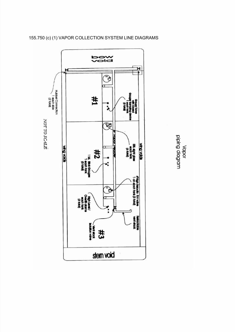
The vapor recovery system on this vessel consists of the following:
1. An eight-inch longitudinal header with a drop into each cargo tank that joins a transverseheader positioned above the cargo headers at the stern.
. The outboard end of each side of the transverse header is equipped with a rising stem gatevalve. . The last 3.3 feet of vapor piping before the vessel vapor connection is painted red/ yellow/red bands and labeled "VAPOR" for ease of identification in the manner required by federalregulations. . Each vapor connection flange is equipped with a 0.5-inch diameter, 1-inch long stud toprevent connecting a cargo hose or loading arm to the vapor system.
1 A four-inch High Velocity P/V valve mounted on each cargo dome. These valves are set at+1.0 PSI pressure, -0.5 oz. vacuum.2 Each cargo tank is equipped with a high level and overfill alarm sensor. The Overfill alarm setpoint is at least 60 seconds before the tank is liquid full when loading at the maximum rate. The High-Level alarm set point is at least 120 seconds before the tank is liquid full when loading at themaximum rate. The sensors connect to the facilities alarm system by a Hubbell connector locatednear the stern3 Each cargo tank is equipped with a stick gauge overfill warning device. This system consistsof a magnetic stick gauge that measures the top 1-meter of the tank.4 An ERL, model SGM -1, sight glass is located on each cargo dome in such a position so as topermit viewing both the ladder rungs and the sump at the end of the cargo piping.
7/27/2019 CHEM1116 TRANSFER PROCEDURE.PDF
http://slidepdf.com/reader/full/chem1116-transfer-procedurepdf 15/21
155.750 (c) (1) VAPOR COLLECTION SYSTEM LINE DIAGRAMS

7/27/2019 CHEM1116 TRANSFER PROCEDURE.PDF
http://slidepdf.com/reader/full/chem1116-transfer-procedurepdf 16/21
USING THE VAPOR RECOVERY SYSTEM
OPERATING PROCEDURES:
When transferring cargo using the vapor recovery system, in addition to following the "Cargo Transfer
Procedures", which are posted on board the vessel, the following procedures are also to be adheredto:
1. Complete all of the pre-transfer checks listed on the previouse.pag
2. All cargo hatches and ullage ports are to be kept closed and dogged at all times during thetransfer.3. Cargo levels may be monitored by looking through the sight glass that is located in eachexpansion dome. The depth of the cargo may be measured by observing the markings on the gaugetree located in each tank.
4. After the transfer is complete, the following steps are to betaken:
Gently push the sticks on the gauges back into their tubes and
replace the caps. Close and latch the covers on the sight glasses. Disconnect overfill alarms cable at Hubbell connection. Close the valve at the vapor connection and bolt a blind on theflange.
PERIODIC TESTING REQUIRED:
1. Annually, the vapor piping will be presented to a Coast Guard Inspector for inspection.Precaution shall be taken to ensure that the personnel exposure is below the STEL. This may beaccomplished by providing a gas free certificate, or other means such as vapor vacuuming,transparent barrier, remote camera, etc.
2. During this inspection, all blinds are to be removed and piping shall be visually inspected
for obstructions. This vessel has 4” inspection ports located in the vapor piping to facilitate andprovide for a complete inspection of the vapor collection system.
3. The vapor header shall be examined internally at least once every 3 months (quarterly) for polymer build up. This is to be accomplished in the following manner:
Remove the P/V valves from the flanges and examine the internal of the pipe and valves. Remove the blind at the forward end of the longitudinal header and from the 3 inspection portsat the "dog leg" and examine the internal of the pipe. Remove the blind at the top of the "T" at the drop into each cargo tank and examine thetransverse section using a mirror and flashlight. Remove the blinds at the ends of the transverse header, open the valve and examine theinterior of this section. Any polymer build up found shall be removed or the effected section replaced.
No vapor hoses are carried on board American Commercial Barge Line barges. If hoses are used for
vapor collection, the terminal will provide them.
7/27/2019 CHEM1116 TRANSFER PROCEDURE.PDF
http://slidepdf.com/reader/full/chem1116-transfer-procedurepdf 17/21
155.750 (c)(2) LOCATION OF SPILL VALVES
The Spill Valves on this vessel are located on the C/L of each cargo tank. The spill valves are setat +3.0 PSI.
155.750 (c)(6) RELIEF SETTINGS FOR VALVES AND P/Vs
This Barge has P/V Valves set at +1.0 PSI Pressure and - 0.5 PSI Vacuum.
155.750 (c)(3) MAXIMUM ALLOWABLE TRANSFER RATE
The vapor collection system installed on this vessel is recommended for a maximum loading rateof 3,500 GPM (5,000 bbl/hr).
55.750 (c)(4) INITIAL TRANSFER RATES
1. The initial flow rate should not exceed 730 bbls/hr:
2. Vessel Person In Charge of the Transfer must monitor pressure/vacuum gauges at thevapor connection to ensure pressure and/or vacuum are normal.
When it has been determined that there is no surface turbulence in a cargo tank and the
systems are operating properly, the flow rate can be increased to the maximum allowable
transfer rate.

7/27/2019 CHEM1116 TRANSFER PROCEDURE.PDF
http://slidepdf.com/reader/full/chem1116-transfer-procedurepdf 18/21
155.750 (c)(5) VAPOR COLLECTION SYSTEM PRESSURE DROP CALCULATIONS

7/27/2019 CHEM1116 TRANSFER PROCEDURE.PDF
http://slidepdf.com/reader/full/chem1116-transfer-procedurepdf 19/21
155.750(c) (7) VAPOR COLLECTION SYSTEM PROCEDURES
Vapors are dispersed and disposed of through hose connections to shore facilities. Vapor hoseconnections at either side of the transverse header vent vapors to shore during loading operations.
Before a transfer using this vessel’s vapor recovery system the following steps must be followed:1. All spill valves shall be manually lifted to ensure free operations.
3. All valves on cargo and vapor line shall be tested for free operation. Any stiff operating valvesshall be inspected for damage, failure, or polymerization and repaired prior to transferringvapors.
2. Check the operation of the P/V valves. . Check that mechanism is free and operating properly.
Check the operation of both the pressure and vacuumside.
. If the mechanism is not operating properly, the valve willrequire dismantling for cleaning or repair.
.
4. Vapor and cargo manifold shall be inspected for polymerization by removing blind flanges andexamining the manifold with explosion proof lighting before making cargo and vapor hoseconnections.
5. Ullages and domes shall be inspected for product polymerization prior to vapor collection. Thisshould be done when personnel exposure is below STEL for the specific cargo to betransferred.
6. Vapor and cargo piping will be visually inspected quarterly. This should be done when personnelexposure is below STEL for the specific cargo to be transferred. If the level is not below the
STEL then the inspection will be deferred until the next gas free. If a non-gas free inspectionmust be made before the next gas free because of suspected polymerization, appropriate stepswill be taken to reduce personnel exposure below STEL limits. These steps may include vapor vacuuming, respiratory devices, transparent barriers or other sufficient means.
155.750(e) OVERFILL PROTECTIONS SYSTEM
Stick Gauge Overfill Devices:
1 Meter stick gauges are located approximately two feet forward of each ullage hatch. They provide a
visual indication of high level and overfill in the cargo tank. Follow these checks before a transfer:
1. Uncap the stick gauges2. Grasp the gauge firmly and pull it up carefully to the fully raised position.3. Lower the stick until it engages the float magnet. This will be near at the bottom of the stick's
travel. The stick must engage the magnet in each tank in order to begin the transfer.4. When the cargo in each tank reaches approximately 1 meter ullage, the float and gauge stick
will begin to rise. It is important to make sure that the stick continues to rise as the tank fills.This will help provide the best indication of the internal cargo level.
5. The gauge sticks are marked with a green band which extends to the 6” before overfill level,followed by a 6” yellow band extending to the overfill level. The remainder of the stick is coloredred. When loading cargo, the green color on the stick indicates the normal loading of the tank,the yellow indicates near over fill (high level) and the red means a dangerous over fill conditionand the compartment cargo valve should be closed immediately.

7/27/2019 CHEM1116 TRANSFER PROCEDURE.PDF
http://slidepdf.com/reader/full/chem1116-transfer-procedurepdf 20/21
155.750(e)(1) ALARM SYSTEM
Each cargo tank is equipped with cargo tank High Level/Overfill Shutdown sensors. The High Levelsensors will activate when the product level reaches 96.5 percent of its capacity. This will occur whenthe product level in the tank is approximately 12” below the deck. The Overflow Shutdown System will
activate at 98 percent capacity or 60 seconds before the tank becomes 100% full at the maximumtransfer rate. This will occur when the product level in the tank is approximately 6” below the deck.These sensors must be connected to the appropriate system before a visual or audio alarm willactivate.
155.750(e)(1) GAUGE TREE
Each cargo tank is equipped with a gauge tree located directly under each sight glass. This tree will
indicate the product level while the vessel is being loaded. The top rung of the gauge tree is at deck
level. The space between each descending rung is 12” with the bottom rung being 3’0” below the deck
level.
Each cargo tank is also equipped with a High Level and Overfill “Paddle” located so as to be visiblefrom each sight glass. The tree lower paddle indicates the product level at the “High Level” setting of the alarm and the upper paddle indicates the product level at the “Overfill” setting of the alarm.
THE ALARM SYSTEM OR GAUGE TREE DOES NOT RELIEVE THE PERSON-IN-CHARGEFROM ANY OF THEIR RESPONSIBILITIES OR DUTIES, BUT ARE TO BE USED AS
ADDITIONAL SAFEGUARDS ONLY.

7/27/2019 CHEM1116 TRANSFER PROCEDURE.PDF
http://slidepdf.com/reader/full/chem1116-transfer-procedurepdf 21/21
155.750 (e)(2) PRE-TRANSFER INSPECTION AND TEST REQUIREMENTS Before a
transfer using this vessel’s vapor recovery system the following steps must be followed:
1. All spill valves shall be manually lifted to ensure free operations.
2. All pressure/vacuum valves shall be checked for free operation. The P/V valves installed should
be checked for free operation in the pressure and vacuum settings.
3. All valves on cargo and vapor line shall be tested for free operation. Any stiff operating valves shallbe inspected for damage, failure, or polymerization and repaired prior to transferring vapors.
4. Vapor and cargo manifold shall be inspected for polymerization by removing blind flanges andexamining the manifold with explosion proof lighting before making cargo and vapor hoseconnections.
5. Ullages and domes shall be inspected for product polymerization prior to vapor collection. Thisshould be done when personnel exposure is below STEL for the specific cargo to be transferred.
6. Stick gauges are located approximately two feet forward of each ullage hatch. They provide avisual indication of the level in the cargo tank. Follow these checks before a transfer:
. Uncap the stick gauges . Grasp the gauge firmly and pull it up carefully to the fully raised position. . Lower the stick until it engages the float magnet. This will be near at the bottom of the
stick's travel. The stick must engage the magnet in each tank in order to begin the transfer. . When the cargo in each tank reaches approximately 39 inches Ullage, the float and gauge
stick will begin to rise. It is important to make sure that the stick continues to rise as the tankfills. This will help provide the best indication of the internal cargo level.
.
7. Test the High Level / Overfill Alarm System for proper operation.
8. Connect the system to the terminal alarm system at the Hubbell connection.
9. Activate the alarm on each tank by operating the manual float lifting device until each alarm hasactivated in both the High level and overfill positions.
10. All sight glasses into cargo tanks shall be inspected to ensure glass is clear and unobstructed.This inspection includes the checking of wipers.
11. The initial loading rate shall be slowed while the Person-in-Charge and shore facility personnelensure the return of vapors back to the shore facility.
12. Throughout cargo and vapor transfer and especially at the initial loading, the Vessel Person InCharge of the Transfer must monitor pressure/vacuum gauges at the vapor connection toensure pressure and/or vacuum are below the maximum design of the vessel.
13. After discharging cargo and before disconnection of shore line, the vapor header shall be
purged of vapors. Manually depress the farthest vapor header pressure relief valve for approximately 1.5 minutes to clear header of all vapors. To equalize atmospheric pressureinside the cargo tanks, depress pressure relief valve
All points outlined above are part of this vessel’s transfer procedures. The declaration of inspectionmust be reviewed and verified by the Person-in-Charge before starting the transfer.