conference paper for sirm2013 - 10th international conference on vibrations in rotating machines
DESCRIPTION
This paper describes the use of contact shims to be inserted between adjacent shrouds of integrally shrouded bladerows for increasing the stiffness and the damping capacity of the blade row. The contact shim, which is protected by thepatent application MI2012A000527, grants continuous contact even if the shrouds tends to open due to the centrifugalload on the blades. The efficiency of the contact shim in reducing vibration amplitudes is demonstrated by means oflinear and non-linear simulations of the static and dynamical behavior of a real blade row equipped with contact shims.TRANSCRIPT

1 Paper ID-256
SIRM 2013 – 10th International Conference on Vibrations in Rotating Machines, Berlin, Germany, 25. – 27. February 2013
Reducing blade vibration amplitudes of integrally shrouded blade rows by means of “contact shims”
Nicolò Bachschmid, Simone Bistolfi, Emanuel Pesatori, Michele Ferrante
R&D Department, Franco Tosi Meccanica S.p.A., piazza Monumento 12, 20025 Legnano, Italy
Abstract
This paper describes the use of contact shims to be inserted between adjacent shrouds of integrally shrouded blade rows for increasing the stiffness and the damping capacity of the blade row. The contact shim, which is protected by the patent application MI2012A000527, grants continuous contact even if the shrouds tends to open due to the centrifugal load on the blades. The efficiency of the contact shim in reducing vibration amplitudes is demonstrated by means of linear and non-linear simulations of the static and dynamical behavior of a real blade row equipped with contact shims.
1 Introduction In literature in the last decades many studies have been performed on the damping mechanism due to friction forces
developing in surfaces in contact, such as tip-shrouds or snubbers (also called tie-bosses) in steam turbine blade rows, or even under platform dampers in gas turbine blade rows (see e.g. [1], [2]) The friction which develops on the contact surfaces is used to reduce the vibration amplitudes of the blades which have generally rather poor damping. In steam turbines the contact between shrouds and between snubbers grants higher stiffness of the blade row as well as some additional damping. Both effects reduce considerably the vibration amplitude with respect to the free standing blade, when the blade row is forced close to resonance by some engine order excitation.
Modeling the effect of the friction contacts is quite cumbersome. Accurate models consider that normal and tangential stiffness of the contact area is increasing with penetration depth as long as this is less than the sum of surface roughness, and become constant when penetration gets higher than surface roughness. Taking account of these non linear effects for the analysis of the dynamic behavior of a blade row with contacting shrouds, would require time step integration of the non linear 3D models for the complete blade row: this calculation is not affordable due to computation time and model complexity. This calculation is affordable if groups of 2 or 4 blades with suitable boundary conditions are considered, as it has been done in [3] and [4] respectively.
2 Blade row natural frequencies Substituting a bonded contact to the friction contact on the contacting surface, the system becomes linear and cyclic
symmetry can be used for calculating the dynamical behavior of the complete row. This is the procedure used by steam turbine designers for calculating the blade row natural frequencies. These frequencies must then be sufficiently far away from different engine order (EO) excitations in order to avoid any possible resonance: this check is made typically on Campbell diagrams, as shown as an example in Fig. 1 which is related to a blade row composed by 12 packs of 10 blades each, with welded shrouds and snubbers. The figure shows the frequencies of 5 different blade pack modes, all with 6 nodal diameters mode shapes over the complete row, which are plotted as function of the rotating speed as well as the first 8 EO excitation frequencies. At rated speed resonances are avoided, but during run up transient some resonances between 6 EO excitation and 6 nodal diameter mode shapes are run through: at 2230 rpm with the third mode (mode X) and at 2590 rpm with the fourth mode (mode U), which could be potentially dangerous due to the fact

2 Paper ID-256
that welded blade packs have very little damping. When accidentally a blade row is strongly excited in resonance, or faces an instability problem, then for avoiding failures more damping should be available: micro-slipping or real slipping contacts in the shroud contact areas could contribute significantly to the vibration amplitude reduction.
The dynamical behavior of integrally shrouded blade rows with friction contact between shrouds cannot be predicted by the linear model with bonded frictionless contacts between the shrouds, but requires different approaches as described e.g. in [5] , [6] and [7]. The results of these studies show the extraordinary effectiveness of the friction contacts in reducing the vibration amplitudes, provided that the normal contact force is in a suitable range (not too high and not too weak).
Figure 1: Campbell diagram with EO excitation (from 1.st to the 8.th): 4 different row modes are considered with 6 nodal diameter modal shapes.
3 Generating a suitable contact pressure In long twisted blades of the last stage of a condenser steam turbine the contact pressure between shrouds and
snubbers at rated speed is granted by the un-twisting deformation of the blades effected by the huge centrifugal force. In shorter blades with different geometry, such as cylindrical blades and slightly twisted blades, the centrifugal force tends generally to open the contact surfaces of the shrouds; the contact pressure must be generated by some pre-stress obtained by means of geometrical interference during assembly operation of the blades in the row of the rotor. Sometimes this is difficult or cumbersome to be performed, especially when the centrifugal load on the blades would force the blade shrouds to diverge and create a considerable gap.
Both effects of integrally shrouded blade rows, the stiffening effect and the damping effect due to the contact forces build up only if a sufficient contact pressure exists between the shrouds, or when during vibration the shrouds get in contact for a consistent portion of the period of vibration. When in operating conditions the blades are stretched by the centrifugal force, a gap between the shrouds may build up; the contact is then lost as well as the stiffening and damping effects. The blades behave like a free standing blade, provided that the relative vibration amplitude in correspondence of the shrouds is smaller than the gap. When the relative vibration amplitude exceeds the gap, then contacts occur with possible shocks, and the absolute vibration amplitude is someway restricted by the so-called snubbing mechanism.
Some features of the snubbing mechanisms have been analyzed with a rather simplified model of the blade row in [8] for tuned blades and in [9] for mistuned blades. In [3] different non linear contact conditions with friction between shrouds of a 3D model of a couple of blades have been extensively analyzed, and the results have shown that small clearances or gaps between shrouds do not affect much the beneficial vibration amplitude reduction provided that

3 Paper ID-256
contact occurs for a consistent portion of the vibration period. But obviously the system behavior becomes non-linear, difficult to predict and stiffening and damping effects are partially lost.
Aim of the present paper is to show how the introduction of a “contact shim” between shrouds can grant a good contact condition also when the gap generated by the centrifugal load is rather large. This will be done analyzing the third last stage (called L-2) of a low pressure steam turbine.
4 Description of the blade row
The effect of the application of contact shims will be shown for a blade row composed by 89 blades of the third last stage (called L-2) of a low pressure steam turbine. All 3D computations have been made with ANSYS 12.1. For the non-linear calculation CONTA174 and TARGE170 elements with isotropic Coulomb friction equal to 0.2 on the contact surfaces have been used. For the group of 6 blades a mesh with 300.000 nodes has been used. For the dynamic analysis more than 100 load cycles are needed before a steady state situation is obtained (due to low damping), and each load cycle is divided in more than 200 small steps for convergence. Only the last 5 load cycles are stored for saving storage capacity, nevertheless up to 90 Gigabytes are used for storing the results. Each single frequency analysis requires around 500 hours on a cluster of 32 processors.
Figure 2: Couple of blades with shrouds initially in contact without pre-stress due to mounting interference, stretched by centrifugal force.
Fig. 2 shows the top of two L-2 blades, which were initially in contact without pre-stress, in the situation in which the blades are stretched by the centrifugal force. The contact between shrouds is lost, and the gap g between the adjacent shrouds is around 400 microns.
To overcome this gap with a suitable pre-stress and related mounting interference, which should also grant a consistent shroud contact pressure at rated speed, seems practically not affordable, also due to the additional stresses which are generated in the roots of the blades due to mounting interference.
The frequency response curve of the couple of blades due to an excitation amplitude defined according to steam turbine manufacturer standards (as e.g. reported in [10]), at an engine order 5 (EO5) which is closest to resonance frequency, is represented in Fig. 3. These standards, based mainly on experience, state that the dynamic excitation is a small percentage of the static steam force, percentage which is decreasing exponentially at the increasing of the blade row natural frequency.
The vibration amplitude of the shroud in tangential direction (shown in Fig. 3) in resonance at 234 Hz is 1.12 mm, and the total maximum vibration amplitude is 1.64 mm, which generates relevant stresses in the blade. With the EO 5 excitation of the blade row, which frequency (250 Hz) is closest to the natural frequency of the free standing blade (234 Hz), the relative displacement of the two shrouds is 186 μm in correspondence of the leading edge and 254 μm at

4 Paper ID-256
the trailing edge, which is much less than the gap existing at rated speed: shrouds do never get in contact and the so-called snubbing effect does not occur, and friction damping in shrouds is not available.
Figure 3: Frequency response curve of the blades of Fig. 2 with EO5 standard excitation.
5 Application of the contact shim
Therefore the only way to reduce the vibration amplitudes is to introduce between the shrouds a “contact shim”, which has the scope of maintaining a contact area and contact pressure between shrouds that have a relevant gap. Due to the contact area and the related contact pressure (generated by the centrifugal force) the contact state can be sticking, at least in a small area of the contact surface. Therefore the contact between shroud and shim can be modeled as bonded but only in the small area. The shrouds are inter-connected this way in the complete row, the system is linear (due to bonded contact) and cyclic symmetry can be used for analyzing its dynamic behavior. The natural frequencies of the row increase with respect to the natural frequencies of the non-contacting blade row, which according to the above said steam turbine manufacturers standards results in lower excitation amplitudes, and in lower stresses. The effect of the friction in the areas where the contact is not sticking but micro-slipping is disregarded in this linear model, but could contribute in vibration amplitude reduction in resonant conditions with some EO excitation..
In resonance conditions with higher excitation levels, or in fluid-dynamic unstable conditions higher vibration levels could be excited, the sticking contact would then be transformed in sliding contact. Then the friction between shim and shrouds will dissipate energy and contribute consistently to maintain vibration amplitudes and related stresses within acceptable levels. The contact shim has at the same time a stiffening function (increasing natural frequencies) and a damping function (adding friction damping to the low damped blade row when in resonance or in instability high vibration amplitudes are excited).
A contact shim inserted between the shrouds of the blades of Fig.2, is shown in Fig.4. For this contact shim and similar types of tuning and damping devices a patent is pending. Fig.5 shows a sectional view of the shim. The length of the shim in this application is smaller than the length of the shrouds, because the shroud geometry was predefined, and it was impossible to accommodate a longer shim between the shrouds. The geometry and more in detail the inclination of the contact surfaces can be chosen in order to get the desired contact pressure. In the present application the angles α and β were chosen both equal to 52°.

5 Paper ID-256
Figure 4: Couple of blades with contact shim. Figure 5: Cross section of shim.
The higher are the angles α and β, the higher is the contact force: when α and β are 60° , the contact force on both sides equals the centrifugal force of the shim if no other forces act on the shim. To avoid ejection of the shim, the thickness h of the shim and the angles must fulfill the condition (1) with respect to the static gap g:
h (cos α + cos β) > g (1)
6 Static behavior of the non-linear model
Due to the deformation of shrouds and shim, the contact surfaces do not remain parallel, as shown in Fig. 6, and consequently contact will occur in operating conditions only in small areas, as is shown in Fig. 7, which represents the contact pressures on the contact shim generated by the centrifugal force acting on shim and shrouds.
Figure 6: Deformed shrouds and shim after loading with centrifugal forces.
The contact pressures are much higher than expected, due to the fact that the deformed shroud presses the shim from bottom towards the contact surfaces. This is confirmed by the rather high contact pressure that appears at the bottom of

6 Paper ID-256
the shim. In this application no clearance was allowed between shim and shrouds in still standing condition. In rotation the contact force acting from bottom on the shim is much higher than the centrifugal force acting on the shim, therefore the desired contact forces on the lateral surfaces of the shim are strongly magnified with respect to the forces which would act on a shim with a sufficient clearance between shim and shrouds. Additional calculations will show the effects of initial clearances.
These are the results of a static non linear computation with friction contact between shrouds and shims, of a group of blades loaded by the centrifugal force. In order to simulate the behavior of the complete row (with circular symmetry) and to take into account the effect of the symmetry, a group of 6 blades have been used with suitable boundary conditions on both sides, that means on the first and last blade of the group (where no separation contact against a fixed wall has been assumed). This way the symmetry could be approximately respected, as can be seen in Fig. 6 where the two internal shrouds and their contact shims shown have very similar deflections.
Figure 7: Actual contact surfaces and contact pressures on shim right and left sides.
It can be seen that the contact shim holds the shrouds and prevents the opening of the contact. The contact forces generated by the centrifugal force on the shim without clearances are huge and grant a sticking contact during normal operating conditions (with standard excitation).
7 Dynamic behavior of the linear cyclic model
The small contact areas are then modeled as bonded and the modal analysis of the cyclic symmetry model of the complete blade row allows to define the natural frequencies.
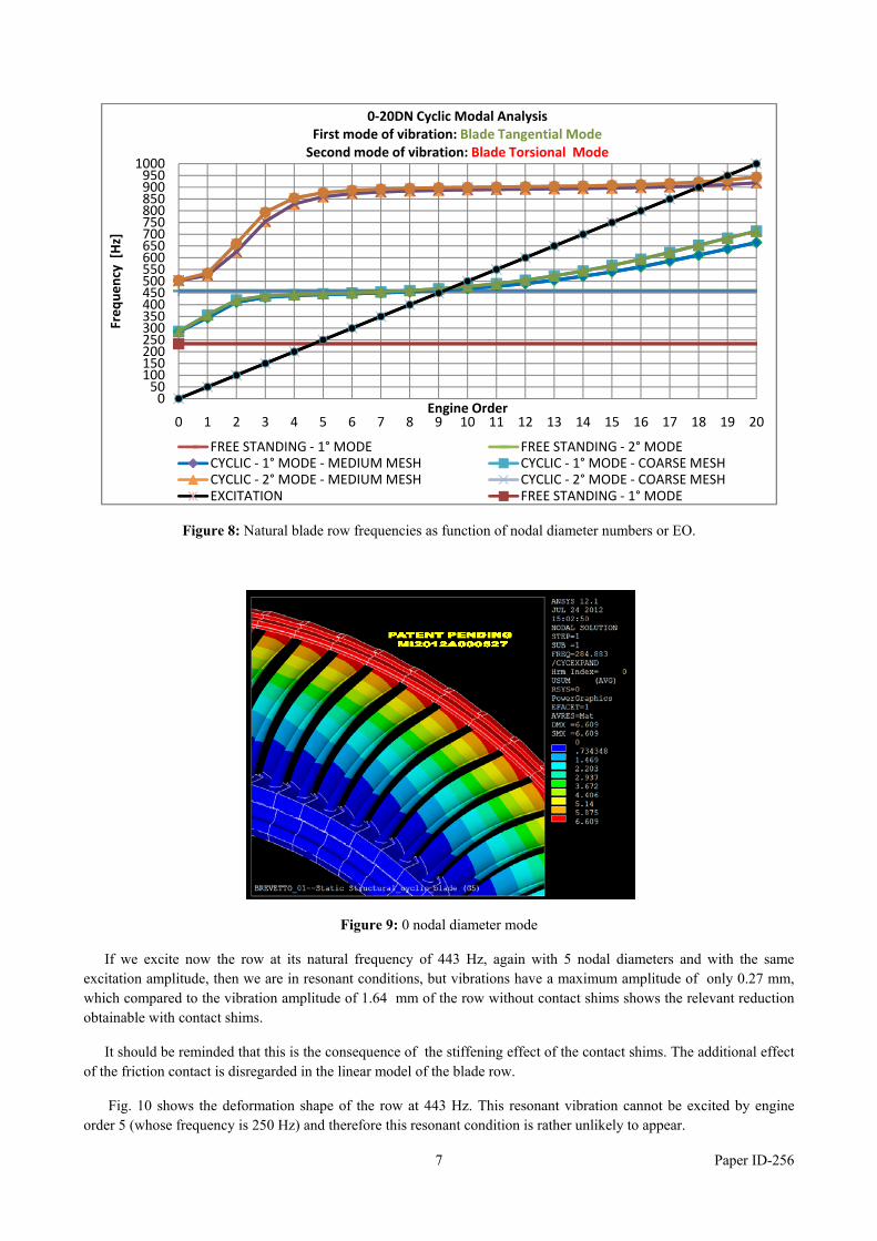
Considering only the first two vibration modes (tangential and torsional) of the free standing blade the different row natural frequencies as function of the nodal diameter number (which equals the EO of excitation) shown in Fig. 8 have been obtained. Also the results of two different meshes (one more refined and the other coarse) are compared in the Figure in order to check the accuracy of the results.
The 0 nodal diameter tangential vibration mode has shifted from 231 Hz to 285 Hz, and the other natural frequencies increase rapidly with the increasing of the number of nodal diameters. The engine order excitation line crosses first the natural frequency curve at 450 Hz close to EO 9, which is a consequence of the predicted increase of the row stiffness. Correspondingly also a reduction of the standard excitation will be obtained.
The deformation shape of the 0 nodal diameter mode is shown in Fig. 9. In this deformation shape it can be assumed that the contact shims are only lightly loaded.
If we try to excite the row with contact shims as we did in Fig. 3 for the row without contact shims, in the range of 230-235 Hz with EO 5, we are obviously far away from resonance, and have a stiffer row. The resulting amplitude is therefore extremely low: only 0.004 mm.
7 Paper ID-256
Figure 8: Natural blade row frequencies as function of nodal diameter numbers or EO.
Figure 9: 0 nodal diameter mode
If we excite now the row at its natural frequency of 443 Hz, again with 5 nodal diameters and with the same excitation amplitude, then we are in resonant conditions, but vibrations have a maximum amplitude of only 0.27 mm, which compared to the vibration amplitude of 1.64 mm of the row without contact shims shows the relevant reduction obtainable with contact shims.
It should be reminded that this is the consequence of the stiffening effect of the contact shims. The additional effect of the friction contact is disregarded in the linear model of the blade row.
Fig. 10 shows the deformation shape of the row at 443 Hz. This resonant vibration cannot be excited by engine order 5 (whose frequency is 250 Hz) and therefore this resonant condition is rather unlikely to appear.
050
100150200250300350400450500550600650700750800850900950
1000
0 1 2 3 4 5 6 7 8 9 10 11 12 13 14 15 16 17 18 19 20
Freq
uency [H
z]
Engine Order
0‐20DN Cyclic Modal Analysis First mode of vibration: Blade Tangential ModeSecond mode of vibration: Blade Torsional Mode
FREE STANDING ‐ 1° MODE FREE STANDING ‐ 2° MODECYCLIC ‐ 1° MODE ‐MEDIUM MESH CYCLIC ‐ 1° MODE ‐ COARSE MESHCYCLIC ‐ 2° MODE ‐MEDIUM MESH CYCLIC ‐ 2° MODE ‐ COARSE MESHEXCITATION FREE STANDING ‐ 1° MODE

8 Paper ID-256
Figure 10: 5 nodal diameter mode.
A resonant condition where engine order coincides with mode shape nodal diameter number occurs at 450 Hz with EO 9. The modal deformation shape of the blade row with 9 nodal diameters is shown in Fig. 11.
Figure 11 : 9 nodal diameter vibration mode.
This mode shows the limits of the linear model with bonded contact in the small contact areas and no contact on the remaining areas, which means that in these areas both separation and penetration can be found, as it is shown in Fig. 11. Separation is possible in reality but penetration not. It can therefore be assumed that the linear model is reliable as long as the vibration amplitudes are vanishing small, and the deformation shape corresponds to a low nodal diameter mode. In other words the linear model allows the calculation of natural frequencies, but when vibration amplitude evaluation is required (e.g. in resonance where high amplitudes are expected) the linear model is not reliable enough.
Nevertheless the linear model has been used for calculating the response of the row to the 9 engine order excitation, which maximum amplitude resulted equal to 0.24 mm, which compared to the amplitude of 1.64 mm of the row without contact shims, demonstrates the efficiency of the contact shims.

9 Paper ID-256
Obviously the damping effect of friction forces cannot be taken into account by the linear model. For this calculation then the non linear model with all kinds of contacts (sticking, slipping and separation) should be used.
8 Non linear dynamic amplitude evaluation
This calculation is affordable only using a reduced model of the blade row, such as the group of 6 blades with suitable boundary conditions, which has been used for the static analysis. Two load steps must be used: first the static (centrifugal and steam) load is applied and then the dynamic load in the second step. The second step is a long lasting transient, with hundreds of load cycles, before a steady state situation is reached, where the vibration amplitude can be evaluated. The calculation has been made with the same 9 EO excitation. Due to difficulties in convergence and in accuracy of the results, the mesh and the time step have been modified.
The linear modal analysis with the new mesh shows a small shift in natural frequencies: the 9 nodal diameter mode has moved from 461 Hz to 468 Hz. Fig. 12 shows the results of the non linear calculation with fine mesh.
Figure 12 : 9 EO excitation on the group of 6 blades with non linear contact conditions and fine mesh.
The vibration amplitudes in all measuring points of the shroud resulted less than 0.1 mm, which is apparently a strong reduction with respect to the frictionless case. But it should be reminded that being the system non-linear the resonance peak may disappear and maximum amplitude could develop at a different frequency. This will be investigated using a simpler model in which the root effects are neglected, for saving computer time.
The friction forces which develop in the contact shim, although small areas of the contact surface remain in sticking conditions during the full load cycle, reduce further the vibration amplitudes. An additional analysis will show the effectiveness of the contact shim when some clearance remains between the bottom of the shim and the shroud.
Additional analyses will show further the behavior of the blades with contact shims in case of higher vibration excitation due to higher steam loads or to fluid-dynamic instability.
The behavior of the blades with contact shims depend also strongly on the contact forces which develop between shim and shroud, which depend on geometry (angles α and β) and clearances. These could then be optimized for having the best performance.

10 Paper ID-256
9 Conclusions
A contact shim used as stiffening and damping device, for which a patent is pending, is described. Its use in integrally shrouded blade rows is beneficial when the centrifugal force tends to create gaps between adjacent shrouds. The contact shim overlaps the gap and recreates suitable contact pressures between shrouds and contact shim. This way the mechanical continuity of the blade row shrouds is re-established, and the overall stiffness of the blade row is consistently increased. In case of necessity, when vibrations are strongly excited in resonance, also the damping effect of the friction forces will reduce further the vibration amplitudes, with respect to the linear (frictionless) model results.
With the aid of linear and non-linear models the computation of the static and dynamical behavior of a blade row equipped with contact shims of a real low pressure steam turbine has been performed, demonstrating the relevant beneficial effects of the application of contact shims. Stiffness of blade row is increased, natural frequencies of the blade row are increased and vibration amplitudes are strongly reduced. A further advantage is that according experience of steam turbine manufacturers, at the increasing of natural frequencies also the expected EO excitation amplitude will reduce, which is again beneficial for the expected vibration amplitudes.
Due to some uncertainties in the model parameters and in the numerical non linear computations, these results should be validated with some experimental results.
10 Acknowledgment
The permission of Franco Tosi Meccanica S.p.A. to publish these results is gratefully acknowledged.
REFERENCES [1] E.P. Petrov, D.J. Ewins (2004): Generic friction models for time-domain vibration analysis of bladed disks. ASME Journal of Turbomachinery, vol. 126, pp. 184-192.
[2] E.P. Petrov, D.J. Ewins (2003): Analytical formulation of friction interface elements for analysis of nonlinear multi-harmonic vibrations of bladed disks. ASME Journal of Turbomachinery, vol. 125, pp. 364-371.
[3] Bachschmid N., Bistolfi S., Chatterton S., Ferrante M., Pesatori E. (2011): Some remarks on the dynamic behaviour of integrally shrouded blade rows. ASME IDETC/CIE 2011, DETC2011-48320.
[4] Ferrante M., Pesatori E., Bachschmid N. (2012): Simulation of the dynamic behaviour of a group of blades with friction contacts. IMECHE VIRM Proceedings pp 313-321.
[5] A. Hohl, C. Siewert, L. Panning, A. Kayser (2008): Non-linear vibration analysis of gas turbine bladings with shroud coupling, ASME TURBO EXPO, GT2008-50787, pp. 1-9.
[6] J. Szwedowicz, R. Visser, W. Sextro, P.A. Masserey (2008): On non linear forced vibration of shrouded turbine blades. ASME Journal of Turbomachinery vol.130, 011002, pp. 1-9.
[7] Yamashita Y., Shiohata K., Kudo T., Yoda H. (2012): Vibration characteristics of a continuous cover blade structure with friction contact surfaces of a steam turbine. IMECHE VIRM Proceedings pp 323-332
[8] Bachschmid, N., Pennacchi, P., Pesatori, E., Turozzi, G., 2007, On the “snubbing” mechanism for reducing blade vibration, ASME Conference DETC2007/VIB-34800, pp 1-10 .
[9] N. Bachschmid, P. Pennacchi, M. Lurati (2008): Combining mistuning and snubbing in bladed disks of turbomachinery, ISMA Conference.
[10] McGuire M., 2004, Steam Turbine Vibration Characteristics. ROVSING Symposium.