control of a ur5e robotic arm through a simulate 2d camera
TRANSCRIPT

Control of a UR5e robotic arm through a simulate 2D camera
Author: Mar Caballer CastellsFacultat de Fısica, Universitat de Barcelona, Diagonal 645, 08028 Barcelona
Advisor: Manel Puig i Vidal & Llorenc Servera SerapioDepartament d’Enginyeria Electronica i Biomedica
Abstract: Industry 5.0 –or fifth industrial revolution- will be focused on the co-operation betweenthe human intelligence and cognitive computing -using collaborative robots. In this paper theUR5e collaborative robot from Universal Robots is the protagonist of an Offline Programming withRoboDK software. To give UR5e the sense of sight a 2D simulated camera is used as a previous stepbefore using the Intel RealSense D-435i. Just 4 steps are needed to know the connection between the2D image view and the scenario and 1 more to move the robotic arm to the user’s desired position.In the present study it is described in detail how that has been achieved, including the descriptionof the roboDK Tree Station and the Python’s data flow diagrams.
I. INTRODUCTION
The word robot comes from the Czech word robota andmeans ”forced labor” or ”slave”. Robotics, and specifi-cally robotic arms -which have similar functions to a hu-man arm-, are present almost in every field in our life,especially in production lines. On one hand, the riseof robotics in industry has increased productivity, re-duced production time and improved production quality.Robots perform a perfectly choreographed dance. On theother hand, it is inevitable that people wonder if robotswill ”steal” their jobs in a few years. [1]
Humans use their senses to collect data from the envi-ronment, being sight the most important of all of them.Unlike humans, robots do not have biological senses and,for this reason, engineers must create them. Sensors arethe senses of robots. In order to mimic human sight,robots can incorporate cameras that, together with com-puter algorithms, allow robots to process visual data fromthe world. Without these sensors, robots are essentiallyblind. This is not a problem for many robotic tasks, butfor some applications sight is useful or even essential.
Although we may think that robots deprive humans ofjob opportunities, they make our lives easier in manyways by doing repetitive or dangerous work. As thename suggests, a cobot (collaborative robot) is a robotdesigned to collaborate side by side with human workersin a shared space. This is why robots are equipped withsophisticated sensors that can make a robot stop whenan operator is too close and resume executing its tasksonce the operator leaves.
This paper provides the opportunity to be one stepcloser to the ultimate goal, which is the control of theUR5e robot with an Intel RealSense Depth Camera D-435i attached to the UR5e’s arm using RoboDK and aOff-Line Programming with Python.
The first step to reach the final goal and which isshown in this article, has been a virtual simulation witha 2D simulate camera and a UR5e library robot usingRoboDK.
II. HARDWARE
A. UR5e robot
UR5e [2] is a collaborative robot arm from the Uni-versal Robot e-Series family which has 4 members- theUR3e, UR5e, UR10 and UR16e. The ‘e’ in e-Seriesstands for empowering, ease of use, everyone and evo-lution. Each member of the family has a different reachand payload but they are all composed of 6 axes (whichare: base, shoulder, elbow, wrist 1, wrist 2 and wrist 3-also called ”six degrees of freedom”). All joins have a360-degree rotation except the UR3e, which has infiniterotation at the end joint.
UR5e is ideal for automating low-weight processingtasks with its 5kg payload and 850 mm reach radiusdesigned to perform a wide range of applications suchas quality control, pick & place, packaging, welding orpainting. In Universal Robot + online showroom we canfind end effectors and accessories designed to complementUR robots.
Universal Robots patented a Graphical User Interface(GUI) called PolyScope that allows operators move therobot’s arm whenever they want and program them us-ing the teach pendant (which is a 12” easy-to-use touch-screen with an intuitive 3D visualization). In UniversalRobots Online Academy we can find free modules thathelp employees with no programming experience quicklyset up and operate with robots. This gives an opportu-nity to gain first-hand knowledge about robots, thereforepreventing additional maintenance expenses.
Universal Robots + and Universal Robots Academyare both in [2].
B. Intel RealSense Depth Camera D-435i
Intel Realsense D435i [3] is part of a Intel RealSenseD400 series of cameras that combines the depth sensingcapabilities of D435 with the addition of an inertial mea-surement unit (IMU). Due to its global shutter image
Control of a UR5e robotic arm through a simulate 2D camera Mar Caballer Castells
capture method –which means that sensors scan the en-tire area of an image at the same time-, the D435i is theappropriate camera for capturing moving objects.
D435i uses an RGB sensor with color image signal pro-cessing.
D435i uses stereo vision to calculate depth. Stereo vi-sion implementation consists of a left imager and a rightimager –simulating human binocular vision- and an op-tional infrared projector -to improve depth accuracy inscenes with non-texture, uniformity or low light. Bothimages are used to obtain a disparity map from whichdepth values are calculated for each pixel.
D435i uses a 6-axis IMU which is composed of a 3-axisaccelerometer and a 3-axis gyroscope. The accelerom-eter is used to measure linear acceleration –in X, Y, Zdirection- and it usually outputs in meters per secondssquared (m/s2), or to measure gravity if the object is notmoving. From these acceleration values we can calculatepitch, roll and yay values, which are defined as the rota-tion around X, Y and Z axis, respectively. The gyroscopeis used to measure angular velocity about the pitch, rolland yay axis and it usually output in radians per second(rad/s).
All these features make the D-435i an ideal candidateamong a wide variety of applications such as drones,robots and virtual reality [4].
For working with Intel Realsense D435i -and with theother IntelRealsense D400 series- there is the open-sourceIntel Realsense Software Development Kit 2.0 (SDK 2.0)which includes Intel Realsense Viewer, Depth qualityTool, Debug Tools, Code Examples and Wrappers.
III. SOFTWARE: ROBODK
RoboDK [5] is a simulator focused on industrial robotapplications which enables robot programs to be created,simulated and generated outside the production environ-ment and without the presence of the robot. That iscalled Off-Line Programming and it has several advan-tages such as the removal of production downtime andthe study of multiple scenarios with the aim of prevent-ing collisions, singularities or reachability issues.
This program offers a Graphical User Interface (GUI)to model the entire workspace and use a realistic modelof the robot. In particular, RoboDK has a library ofover 500 robots from 50 different manufacturers includ-ing ABB, Fran, Kuka, Yaskawa/Motoman and UniversalRobots. All items in the RoboDK station –robots, tools,reference frames, objects, targets and much more- areshown in the station tree, which allows intuitive under-standing and modifying item’s dependencies.
To build these robot programs there is a generic way,without the need to write code, which enables basic robotprogramming for less experienced users. Despite this,simulations and programs can also be fully created usingthe RoboDK’s Application Program Interface (API) and
a specific programming language, as for example Python,C++, Visual Basic or Matlab. In particular, RoboDKAPI for Python, the programming language that is usedin this article, includes the Robolink and Robodk mod-ules. On the one hand, the Robolink module is the bridgebetween Robodk and Python. On the other hand, theRobodk module includes a robotics toolbox for Python.
In [5] it can be found how to download RoboDK –it isrecommended to install RoboDK using the default set-tings in our case, since we use Python language-, doc-umentation, tips and tricks, examples and the RoboDKforum (an active forum with a quick replies), among oth-ers.
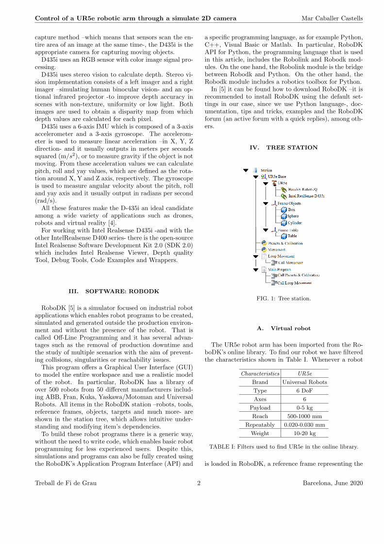
IV. TREE STATION
FIG. 1: Tree station.
A. Virtual robot
The UR5e robot arm has been imported from the Ro-boDK’s online library. To find our robot we have filteredthe characteristics shown in Table I. Whenever a robot
Characteristics UR5e
Brand Universal Robots
Type 6 DoF
Axes 6
Payload 0-5 kg
Reach 500-1000 mm
Repeatably 0.020-0.030 mm
Weight 10-20 kg
TABLE I: Filters used to find UR5e in the online library.
is loaded in RoboDK, a reference frame representing the
Treball de Fi de Grau 2 Barcelona, June 2020
Control of a UR5e robotic arm through a simulate 2D camera Mar Caballer Castells
robot base is added to the tree station. In the presentRoboDK program, due to some functions that we are go-ing to use later return the pose (position and orientation)with respect to the absolute reference frame, it is impor-tant that the base reference position with respect to theRoboDK station –the absolute reference- is zero in X, Y,Z, roll, pich and yaw.
B. Tools
The first tool in our station is the Hand-E AdaptiveGripper from RobotiQ [6]. However, in our work, thistool does not perform the function of gripping, but movesthe Tool Center Point (TCP) into the desired position.
The second tool in our station is an Intel RealsenseD-435i 3D object connected to a module which allowsthe fixing of the camera to the robotic arm. The cameraobject and the support module were designed separatelyby other people that have studied the physical character-istics and dimensions of the D-435i and the UR5’s finaleffector, using a 3D design software named Autodesk Fu-sion 360 [7].
In this work, we use this program again to fusion thesetwo 3D designs in order to create a unique camera &support object. To convert an object into a tool, it hasbeen done by dragging and dropping this object (in STLformat) into the robot item within the tree station.
Inside the Connect Menu section available in the MainMenu -which is located at the top of the main RoboDK’sinterface- you can simulate a 2D camera. It is necessaryto select one item to attach the simulated camera, whichin our case is the camera & support tool. Many cameraparameters can be adjusted in a pop-up window, but inour case, although this procedure was useful to test thepossibilities of the simulation, we configured all parame-ters using Python commands.
The TCP position with respect to the robot flange ofeach tool, can be modified with a double click at theappropriate Robot Tool in the robot Tree. In our case,the TCP positions are the middle of the end gripper’sposition and in the middle of the camera, respectively.
The last important thing is knowing which one is activein each moment, and we control this by using Pythoncommands.
C. Reference Frames and Objects
The next step in our tree station design has been thedefinition of two Reference Frames: one for the objecttable –named Frame Table- and another for the objectson the table which are a box, a sphere and a cylinder–named Frame Objects.
To add a new reference frame, we select the Add Refer-ence Frame equivalent button in the toolbar. The objectsmentioned above have been imported from RoboDK’s li-brary and then they have been scaled and colored at our
discretion.
D. Presets & Calibration python Program
First, the program adjusts the focal length (in mm),the field of view (in degrees), the far length -maximumworking distance- (in mm) and the size of the sensor (inpixels).
Second, the program uses the path of RoboDK stationto search the calibration.txt file. If the file exists, theprogram reads the 5 first lines (which are the pose fromthe previous run -calibration pose-) and, if it matcheswith the current pose, it means that the calibration hasbeen done before and this first program finishes. If thefile does not exist or the calibration pose does not matchwith the current pose, we have to calibrate. Calibrationis done in 4 steps:
1. Click on one point on the simulate 2D camera view.Shown in Fig. 4.A.1.
2. Click on the corresponding point on the RoboDKscenario. Shown in Fig 4.B.2.
3. Click on another point on the simulate 2D cameraview. Shown in Fig 4.A.3.
4. Click on the corresponding point on the RoboDKscenario. Shown in Fig 4.B.4.
Once this process is finished, calibration data is savedin the calibration.txt file -if the file does not exist, itis created. The flow chart of this program is shown inFigure 2.
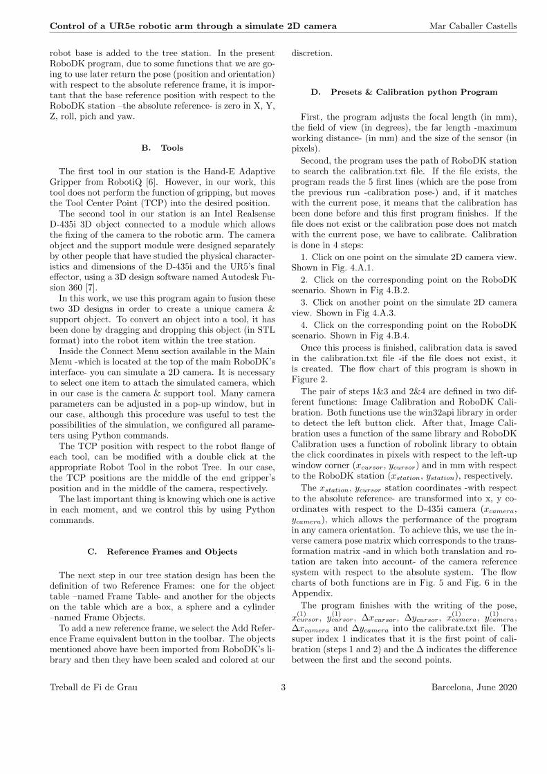
The pair of steps 1&3 and 2&4 are defined in two dif-ferent functions: Image Calibration and RoboDK Cali-bration. Both functions use the win32api library in orderto detect the left button click. After that, Image Cali-bration uses a function of the same library and RoboDKCalibration uses a function of robolink library to obtainthe click coordinates in pixels with respect to the left-upwindow corner (xcursor, ycursor) and in mm with respectto the RoboDK station (xstation, ystation), respectively.
The xstation, ycursor station coordinates -with respectto the absolute reference- are transformed into x, y co-ordinates with respect to the D-435i camera (xcamera,ycamera), which allows the performance of the programin any camera orientation. To achieve this, we use the in-verse camera pose matrix which corresponds to the trans-formation matrix -and in which both translation and ro-tation are taken into account- of the camera referencesystem with respect to the absolute system. The flowcharts of both functions are in Fig. 5 and Fig. 6 in theAppendix.
The program finishes with the writing of the pose,
x(1)cursor, y
(1)cursor, ∆xcursor, ∆ycursor, x
(1)camera, y
(1)camera,
∆xcamera and ∆ycamera into the calibrate.txt file. Thesuper index 1 indicates that it is the first point of cali-bration (steps 1 and 2) and the ∆ indicates the differencebetween the first and the second points.
Treball de Fi de Grau 3 Barcelona, June 2020

Control of a UR5e robotic arm through a simulate 2D camera Mar Caballer Castells
FIG. 2: Flow chart of the Presets & Calibration program.
E. Movement Python Program
This program reads the calibration.txt file and whenwe click on the image (shown in Fig 4.A.a, Fig 4.A.b,Fig 4.A.c) -as all the calibration data are coordinateswith respect to the camera (in mm) and respect to whatthe camera is viewing (in pixels)- once the position of thecurrent click (in pixels) is calculated, the program doesa lineal transformation to obtain the x, y current clickcoordinates (in mm) with respect to the camera. This isdone by using the following equation:
x = x(1)camera +
xcursor − x(1)cursor
∆xcursor∆xcamera (1)
-and the equivalent for the Y coordinate.
FIG. 3: Flow chart of the Movement program.
Finally, we use the camera pose matrix to transformthe click coordinates in the camera reference system tothe absolute reference system. This is the final targetwhere the Hand-E RobotiQ moves (shown in Fig 4.C.a,Fig 4.C.b, Fig 4.C.c).
The flow chart of this program is shown in Figure 3.
F. Loop Movement and Main Program
The Main RoboDK program consists of two calls:
1. The first call is to the Presets & Calibration pro-gram.
2. The second call is to the Movement program andit runs in a loop until the end of the program when theuser right clicks the window and then clicks Esc key.
Treball de Fi de Grau 4 Barcelona, June 2020

Control of a UR5e robotic arm through a simulate 2D camera Mar Caballer Castells
FIG. 4: A: Simulate 2D camera view. B: RoboDK scenario. C: Final movement in three different positions (a , b and c).A complete execution of our program is shown in this figure. First, we must follow in order the black cursor numbered sequence-1, 3 are in Fig. 4.A and 2, 4 are in Fig. 4.B- which represents the four calibration steps. Second, we must match withe cursorsa, b and c -which are in Fig. 4.A- with the final movement a, b and c -which are in Fig. 4.C- respectively.
V. RESULTS AND CONCLUSIONS
A virtual simulation program using a 2D simulate cam-era and an UR5e library robot has been developed us-ing RoboDK. With a simple-to-use calibration –only fourclicks- you can configure the sense of sight of the robot,creating the possibility of knowing the environment –inour case a virtual scenario- and of approaching to theposition decided by the user.
This offline program automatically saves data calibra-tion, avoiding the waste of time when the program is run-ning with the previous pose –position and orientation- ofthe camera. An interesting improvement is the possibil-ity to decide if each point of calibration interests us orwe want to repeat it.
2D simulated camera is limited by the absence of depthdistance in each point of the scenario. In this work thedepth coordinates are fixed as z = zcamera-100 ( z is thedistance with respect to the camera view, zcamera is thedistance with respect to the absolute reference and 100 isthe size of the objects in the scenario -all in mm-). With
this configuration, if the camera is looking down in anydirection -such as in Fig. 4- when we convert the coordi-nate with respect to the absolute reference, the grippermoves above the objects. But, if we have another orien-tation, only the x and y coordinates are right.
This study has been very helpful in guiding futurework. Depth limitations shall automatically terminatewith Intel RealSense D-435i and it would be only neces-sary to adapt this program structure to the 3D camera-with all the difficulties that come with it. The ultimategoal will provide a better sense of sight and with this,more opportunities.
Acknowledgments
I would like to express my gratitude to my advisor,Dr. Manel Puig i Vidal for his guidance and supportduring these months. A very special thanks to Carla forher patience and encouragement: nobody has been moreimportant to me. Finally, I wish to thank all my family:without them, nothing would have been possible.
[1] G. Graetz, G.Michaels, Robots at Work, The Review ofEconomics and Statistics, 100: 753-768, 2018.
[2] Collaborative robotic automation | Cobots from UniversalRobots. (n.d.). [Online] Retrieved March 5, 2020, fromhttps://www.universal-robots.com/
[3] Intel Realsense - Depth and Tracking cameras(n.d.). [Online] Retrieved March, 5, 2020, fromhttp://intelrealsense.com/
[4] Z. Li, S. Dian,C.Li Research on Virtual 3D Display andTeleoperation Technologies for an Inspection Robot in aStream Generator, In Proceedings of the 2019 4th Inter-
national Conference on Automation, 57: 1-5, 2019.[5] Simulator for industrial robots and offline programming-
RoboDK. (n.d.). [Online] Retrieved March, 5, 2020, fromhttp://robodk.com/
[6] Start Production Faster | RobotiQ. (n.d.). [Online] Re-trieved April, 10, 2020, from https://www.robotiq.com/
[7] Autodesk | 3D Design, Engineering & Construction Soft-ware. (n.d.). [Online] Retrieved April, 15, 2020, fromhttps://www.autodesk.com/
Treball de Fi de Grau 5 Barcelona, June 2020
Control of a UR5e robotic arm through a simulate 2D camera Mar Caballer Castells
VI. APPENDIX
FIG. 5: Flow chart of the Image Calibration program.FIG. 6: Flow chart of the Image Calibration program.
Treball de Fi de Grau 6 Barcelona, June 2020