crystal structure lec
TRANSCRIPT

7/31/2019 Crystal Structure Lec
http://slidepdf.com/reader/full/crystal-structure-lec 1/52
Crystal Structure
7/31/2019 Crystal Structure Lec
http://slidepdf.com/reader/full/crystal-structure-lec 2/52
SUBCONTENT:
Crystal structures. Fundamental Concept
Unit cell
Material crystal system
Efficiency of atomic packing
Polymorphism and allotropic transformation
Crystallography plane and direction

7/31/2019 Crystal Structure Lec
http://slidepdf.com/reader/full/crystal-structure-lec 3/52
You should be able:
• Differentiate between crystalline, noncrystalline, single
crystal and polycrsytal.
• Derive the relationship between unit cell edge length andatomic radius for face centered and body centered cubic
• Compute density and atomic packing factors for crystal
• Specify the miller indices for crystallography plane anddirection
• Relate the crystal structure with material properties
LEARNING OBJECTIVE

7/31/2019 Crystal Structure Lec
http://slidepdf.com/reader/full/crystal-structure-lec 4/52
Fundamental concept:
Classification of solid materials
Solid materials
CrystallineMaterial
Single Crystal polycrystal
Noncrsytallinematerial
(Amorphous)

7/31/2019 Crystal Structure Lec
http://slidepdf.com/reader/full/crystal-structure-lec 5/52
Fundamental concept: Crystalline
material
Crystalline material- atoms, molecules or ion packed in aregularly ordered, repeating pattern, extending in 3 spatial
dimension.
Properties of crystalline materials depend on the crystalstructure
Crystal structure
is a unique arrangement of atoms in a crystal.
composed of a unit cell

7/31/2019 Crystal Structure Lec
http://slidepdf.com/reader/full/crystal-structure-lec 6/52
• Formation crystal structure depends
– Chemistry of fluid
– Condition under which is being solidified
– Ambient pressure
• Crystallization-Process forming crystalline
structures.

7/31/2019 Crystal Structure Lec
http://slidepdf.com/reader/full/crystal-structure-lec 7/52
• atoms pack in periodic, 3D arrays
• typical of:
Crystalline materials...
-metals-many ceramics-some polymers
• atoms have no periodic packing • occurs for:
Noncrystalline materials...
-complex structures
-rapid cooling
crystalline SiO2
noncrystalline SiO2
"Amorphous" = Noncrystalline

7/31/2019 Crystal Structure Lec
http://slidepdf.com/reader/full/crystal-structure-lec 8/52
•No recognizable long-
range order
•Completely ordered
•In segments
•Entire solid is made up
of atoms in an orderlyarray
Amorphous
Polycrystalline
Crystal
•Atoms are disordered
•No lattice
•All atoms arranged ona common lattice
•Different latticeorientation for eachgrain

7/31/2019 Crystal Structure Lec
http://slidepdf.com/reader/full/crystal-structure-lec 9/52
19
• Single Crystals
-Properties vary withdirection: anisotropic.
-Example: the modulusof elasticity (E) in BCC iron:
• Polycrystals
-Properties may/may notvary with direction.
-If grains are randomly
oriented: isotropic.(Epoly iron = 210 GPa)
-If grains are textured,anisotropic.
200 mm
SINGLE VS POLYCRYSTALS

7/31/2019 Crystal Structure Lec
http://slidepdf.com/reader/full/crystal-structure-lec 10/52
10
• Some engineering applications require single crystals:
--diamond singlecrystals for abrasives
--turbine blades
• Most engineering materials are polycrystals.
grain

7/31/2019 Crystal Structure Lec
http://slidepdf.com/reader/full/crystal-structure-lec 11/52
• Unit cell - smallest structural unit or building block that can describe thecrystal structure. Repetition of the unit cell generates the entire crystal.
• Primitive unit cell- smallest possible unit cell one can construct.
• Lattice parameters- spacing between unit cells in various direction.

7/31/2019 Crystal Structure Lec
http://slidepdf.com/reader/full/crystal-structure-lec 12/52
Concept test
which one isunit cell

7/31/2019 Crystal Structure Lec
http://slidepdf.com/reader/full/crystal-structure-lec 13/52
13
The atomic arrangements inthe different crystal systems
affect mechanical behavior.
1.5 CRYSTAL SYSTEM AND CRYSTALLOGRAPHY
•By adding additional lattice point to 7 basic crystal systems – form 14 Bravais
lattice.
•However, most metals exhibit one of three crystal structure – BCC, FCC & HCP
•The crystal systems are a grouping of crystal structures that used to describetheir lattice.
•Each crystal system consists of a set of three axes in a particular geometricalarrangement.
•There are only 7 crystal systems that atoms can pack together to produce aninfinite 3D space lattice :•cubic, hexagonal, tetragonal, rhombodhedral, orthorhombic, monoclinic, triclinic.
Crystal System
7/31/2019 Crystal Structure Lec
http://slidepdf.com/reader/full/crystal-structure-lec 14/52
14
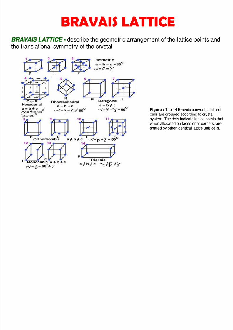
BRAVAIS LATTICE
Figure : The 14 Bravais conventional unitcells are grouped according to crystalsystem. The dots indicate lattice points that
when allocated on faces or at corners, areshared by other identical lattice unit cells.
BRAVAIS LATTICE - describe the geometric arrangement of the lattice points andthe translational symmetry of the crystal.

7/31/2019 Crystal Structure Lec
http://slidepdf.com/reader/full/crystal-structure-lec 15/52
15
FACE CENTRED CUBIC(FCC)
HEXAGONAL CLOSEDPACK (HCP)
SIMPLE CUBIC (SC)
BODY CENTRED CUBICBCC
CRYSTAL STRUCTURE OF METALS

7/31/2019 Crystal Structure Lec
http://slidepdf.com/reader/full/crystal-structure-lec 16/52
16
Types of crystal structure Examples
Simple cubic Cube where atoms lie on a grid.
No. of atom at corner = 8x1/8 = 1 atom
Total no. of atom in 1unit cell = 1 atom
Manganese
Body centered cubic(BCC)
*Lower ductility but a higher yield strength than FCC metals.
Cube with an atom at each corner and one in the center.
No. of atom at corner = 8x1/8 = 1 atomNo. of atom at center = 1 atomTotal no. of atom in 1unit cell = 2 atoms
Chromium,Tungsten(W),Molybdenum,Vanadium(V)
CRYSTAL STRUCTURE OF METALS
Most metals (about 90%) crystallize upon solidification into three densely packed crystal
structures as shown below (BCC,FCC,HCP). However, simple cubic crystals are rather rare whichcan be viewed as simple cubic grid.

7/31/2019 Crystal Structure Lec
http://slidepdf.com/reader/full/crystal-structure-lec 17/52
17
Types of crystal structure Examples
Face centered cubic (FCC)
* Atoms for FCC are more densely packed than BCC.
Cube with an atom at each corner, one in the center and one in thecenter of each side of the cube.
No. of atom at corner = 8x1/8 = 1 atom
No. of atom at face = 6x1/2 = 3 atomTotal no. of atom in 1unit cell = 4 atoms
Aluminum,Nickel, Copper,Gold, Lead,Platinum
Hexagonal close-packed(HCP)
•Because of the spacing of the lattice structure, rows of atoms do not easily slide over one another in HCP --- have lower plasticity and ductility than cubic structures.
*Atoms are as densely packed as in the FCC unit cell. Difference--- Arrangement of the atoms
Hexagon with a reference atom that is surrounded by 12 atoms that areequal distance from the reference atom.
No. of atom at corner for top face = 6x1/6 = 1 atomNo. of atom at corner for bottom face = 6x1/6 = 1 atomNo. of atom at centre = 3 atomsNo. of atom at centre for top face = 1x1/2 = 1/2 atom
No. of atom at centre for bottom face = 1x1/2 = 1/2 atomTotal no. of atom in 1unit cell = 6 atoms
Magnesium,Beryllium, Zinc,Cadmium,Titanium,Zirconium (Zr)
7/31/2019 Crystal Structure Lec
http://slidepdf.com/reader/full/crystal-structure-lec 18/52
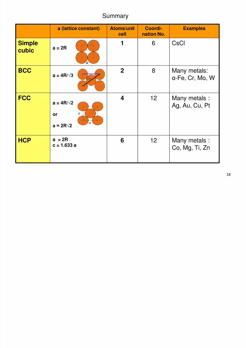
18
a (lattice constant) Atoms/unitcell
Coordi-nation No.
Examples
Simplecubic
a = 2R 1 6 CsCl
BCCa = 4R/√3
2 8 Many metals:α-Fe, Cr, Mo, W
FCCa = 4R/√2
or
a = 2R√2
4 12 Many metals :Ag, Au, Cu, Pt
HCP a = 2Rc = 1.633 a
6 12 Many metals :Co, Mg, Ti, Zn
Summary

7/31/2019 Crystal Structure Lec
http://slidepdf.com/reader/full/crystal-structure-lec 19/52

7/31/2019 Crystal Structure Lec
http://slidepdf.com/reader/full/crystal-structure-lec 20/52
20
APF = no. of atom/unit cell, n x volume of atoms in the unit cell, (Vs)volume of the unit cell, (Vc)
ATOMIC PACKING FACTOR
•Atomic packing factor (APF) is defined as the efficiency of atomic arrangementin a unit cell.
•It is used to determine the most dense arrangement of atoms. It is because howthe atoms are arranged determines the properties of the particular crystal.
•It is represented mathematically by :

7/31/2019 Crystal Structure Lec
http://slidepdf.com/reader/full/crystal-structure-lec 21/52
21
EXAMPLE
• APF for a simple cubic structure = 0.52
Calculate the APF for Simple Cubic (SC)?

7/31/2019 Crystal Structure Lec
http://slidepdf.com/reader/full/crystal-structure-lec 22/52
22
EXERCISE
a) BCC b) FCC
Calculate the APF for BCC and FCC ?

7/31/2019 Crystal Structure Lec
http://slidepdf.com/reader/full/crystal-structure-lec 23/52
23
DENSITY COMPUTATIONS
• A knowledge of the crystal structure of a metallicsolid permits computation of its density through the
relationship :
Where
ρ = n AVc NA
n = number of atoms associated with each unit cell
A = atomic weightVc = volume of the unit cellNA = Avogadro’s number (6.023 x 10²³ atoms/mol)

7/31/2019 Crystal Structure Lec
http://slidepdf.com/reader/full/crystal-structure-lec 24/52
24
Calculate the density for nickel (simple cubic structure).Note that the unit cell edge length (a) for nickel is 0.3524 nm.
EXAMPLE
The volume (V) of the unit cell is equal to the cell-edge length (a) cubed.
V = a3 = (0.3524 nm)3 = 0.04376 nm3
Since there are 109 nm in a meter and 100 cm in a meter, there must be 107 nm in a cm.109 x 1m = 107 nm/cm1 m 100 cm
We can therefore convert the volume of the unit cell to cm3 as follows.4.376 x 10-2 nm3 x [1 cm ]3 = 4.376 x 10⁻²³ cm 3
107 nm
The mass of a nickel atom can be calculated from the atomic weight of this metal and Avogadro’snumber.
58.69g Ni x 1 mol = 9.746 x 10⁻²³ g/atom 1(9.746 x 10⁻²³ g/unit cell) = 2.23 g/cm3 1 mol 6.023 x 10²³ atoms 4.376 x 10⁻²³ cm 3 /unit cell

7/31/2019 Crystal Structure Lec
http://slidepdf.com/reader/full/crystal-structure-lec 25/52
25
Crystalstructure, 20oC
Density of solid,20oC (g/cm3)
Copper has an atomic radius of 0.128 nm, FCC crystal structure and an atomicweight of 63.5 g/mol. Compute its density and compare the answer with itsmeasured density.
Element Symbol
AtomicNumber
Atomicweight(amu)
Atomicradius(nm)
Chromium Cr 24 52.00 7.19 BCC 0.125
Cobalt Co 27 58.93 8.9 HCP 0.125
Copper Cu 29 63.55 8.94 FCC 0.128
Solution :
ρ = n A
Vc NA
EXERCISE

7/31/2019 Crystal Structure Lec
http://slidepdf.com/reader/full/crystal-structure-lec 26/52
Polymorphism allotropic
transformation
• the ability of a solid material to exist in more
than one form or crystal structure.
• Example: Carbon and iron

7/31/2019 Crystal Structure Lec
http://slidepdf.com/reader/full/crystal-structure-lec 27/52
Allotropy: Carbon
Graphite Diamond

7/31/2019 Crystal Structure Lec
http://slidepdf.com/reader/full/crystal-structure-lec 28/52
28
ALLOTROPIC TRANSFORMATION
• A material that can exist in more than one lattice structure (depending ontemperature-heating@cooling) allotropic.
• An allotropic material is able to exist in two or more forms having variousproperties without change in chemical composition.
• E.g : When metals are heated slowly from room temperature to their meltingpoints (liquid state), most metals (Cu,Al) do not change their crystalline latticestructure before becoming a liquid. However, this in not the case with steel, Ti,iron and many iron alloys.
Upon heating pure iron experiences two changes in crystal structure

7/31/2019 Crystal Structure Lec
http://slidepdf.com/reader/full/crystal-structure-lec 29/52
29
912°C
1394°C
1538°C
768°C
Allotropy of iron(Fe)
BCC (delta iron-high T) FCC (austenite-moderate T) BCC (alfa iron-low T)
Upon heating, pure iron experiences two changes in crystal structure.
At room temperature, it exists as ferrite,or α iron (BCC).
When we heat it to 912°C, it experiences an allotropic transformation to austenite,or γ iron (FCC).
At 1394°C, austenite reverts back to a BCC phase called δ ferrite.

7/31/2019 Crystal Structure Lec
http://slidepdf.com/reader/full/crystal-structure-lec 30/52
30
Miller indices is used to label the planes and directions of atoms in a crystal.
Why Miller indices is important?To determine the shapes of single crystals, the interpretation of X-raydiffraction patterns and the movement of a dislocation , which may determinethe mechanical properties of the material.
MILLER INDICES

7/31/2019 Crystal Structure Lec
http://slidepdf.com/reader/full/crystal-structure-lec 31/52
31
i) Determine the points at which a given crystal planeintersects the three axes, say at (a,0,0),(0,b,0), and (0,0,c). Ifthe plane is parallel an axis, it is given an intersection ∞.
ii) Take the reciprocals of the three integers found in step (i).
iii) Label the plane (hkl). These three numbers are expressedas the smallest integers and negative quantities are indicatedwith an overbar,e.g : a.
MILLER INDICES OF A PLANE
How to determine crystal plane indices?
Figure : Planes with different Millerindices in cubic crystals
Axis X Y ZInterceptions
Reciprocals
Reduction (if necessary)
Enclosed (h k l )

7/31/2019 Crystal Structure Lec
http://slidepdf.com/reader/full/crystal-structure-lec 32/52
32
Axis X Y Z
Interceptions ½ 1 ½
Reciprocals 2 1 2
Reduction (if necessary)
Enclosed (2 1 2)
EXAMPLE : CRYSTAL PLANE INDICES
0
1
1
1
10
1
1
½
½
Axis X Y Z
Interceptions 1 1 1
Reciprocals
Reduction (if necessary)
Enclosed (1 1 1)

7/31/2019 Crystal Structure Lec
http://slidepdf.com/reader/full/crystal-structure-lec 33/52
33
Axis X Y Z
Interceptions 1 1 ∞
Reciprocals 1 1 0
Reduction (if necessary)
Enclosed (1 1 0)
0
1
1
1
Axis X Y Z
Interceptions 1 ∞ ½
Reciprocals 1 0 2
Reduction (if necessary)
Enclosed (1 0 2)
5/6
⅓
Two numbers in one axes
0

7/31/2019 Crystal Structure Lec
http://slidepdf.com/reader/full/crystal-structure-lec 34/52
34
Axis X Y Z
Interceptions ∞ 1 ½
Reciprocals 0 1 2
Reduction (if necessary)
Enclosed (0 1 2)
½
Plane pass through origin
0
Axis X Y Z
Interceptions ∞ 1 ∞
Reciprocals 0 1 0
Reduction (if necessary)
Enclosed (0 1 0)0

7/31/2019 Crystal Structure Lec
http://slidepdf.com/reader/full/crystal-structure-lec 35/52
35
Determine the Miller Indices plane
for the following figure below?
Answer :a) (121)
b) (210)
c) (111)
a)
0
1
1
1
Axis x y z
Intercepts
Reciprocals
Reduction(if necessary)
Enclosed ( )
½

7/31/2019 Crystal Structure Lec
http://slidepdf.com/reader/full/crystal-structure-lec 36/52
Answer :a) (121)
b) (210)
c) (111)
b)
0
1
1
Axis x y z
Intercepts
Reciprocals
Reduction(if necessary)
Enclosed ( )
½

7/31/2019 Crystal Structure Lec
http://slidepdf.com/reader/full/crystal-structure-lec 37/52
Answer :
a) (121)
b) (210)
c) (111)c)
0
1
1
1
c)
Axis x y z
Intercepts
Reciprocals
Reduction
(if necessary)
Enclosed ( )

7/31/2019 Crystal Structure Lec
http://slidepdf.com/reader/full/crystal-structure-lec 38/52
Axis x y z
Intercepts
Reciprocals
Reduction(if necessary)
Enclosed ( )
Answer :a) (121)
b) (210)
c) (111) c)
0
1
1
1
d)
⅗ ⅕

7/31/2019 Crystal Structure Lec
http://slidepdf.com/reader/full/crystal-structure-lec 39/52
Determine the Miller indices of a cubic crystal plane that intersects the position coordinates
A (1, 1/4, 0), B (1, 1, 1/2) ,C (3/4, 1, 1/4) and D (1/2, 1, 0) ?
Answer : ( 6 4 6 )
Axis x y z
Intercepts
Reciprocals
Reduction
(if necessary)
Enclosed ( )
7/31/2019 Crystal Structure Lec
http://slidepdf.com/reader/full/crystal-structure-lec 40/52
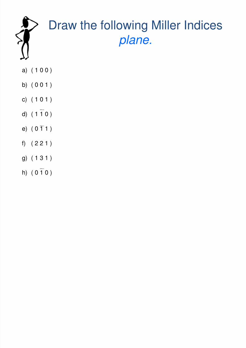
Draw the following Miller Indices
plane.
a) ( 1 0 0 )
b) ( 0 0 1 )
c) ( 1 0 1 )
d) ( 1 1 0 )
e) ( 0 1 1 )
f) ( 2 2 1 )
g) ( 1 3 1 )
h) ( 0 1 0 )

7/31/2019 Crystal Structure Lec
http://slidepdf.com/reader/full/crystal-structure-lec 41/52
41
MILLER INDICES OF A DIRECTION
How to determine crystal direction indices?i) Determine the length of the vector
projection on each of the three axes,based on .
ii) These three numbers are expressed as thesmallest integers and negative quantitiesare indicated with an overbar.
iii) Label the direction [hkl]. Figure : Examples of direction
Axis X Y Z
Head (H) x2 y2 z2
Tail (T) x1 y1 z1
Head (H) –Tail (T) x2-x1 y2-y1 z2-z1
Reduction (if necessary)
Enclosed [h k l]
* No reciprocal involved.

7/31/2019 Crystal Structure Lec
http://slidepdf.com/reader/full/crystal-structure-lec 42/52
42
Axis X Y Z
Head (H) 1 0 ½
Tail (T) 0 0 0
Projection (H-T) 1 0 ½
Reduction (if necessary) * 2 2 0 1
Enclosed [2 0 1]
EXAMPLE : CRYSTAL DIRECTION INDICES
0½
1
1
Axis X Y Z
Head (H) 1 0 0
Tail (T) 0 1 0
Projection (H-T) 1 1 0
Enclosed [1 1 0]0
1
1
1
1
7/31/2019 Crystal Structure Lec
http://slidepdf.com/reader/full/crystal-structure-lec 43/52
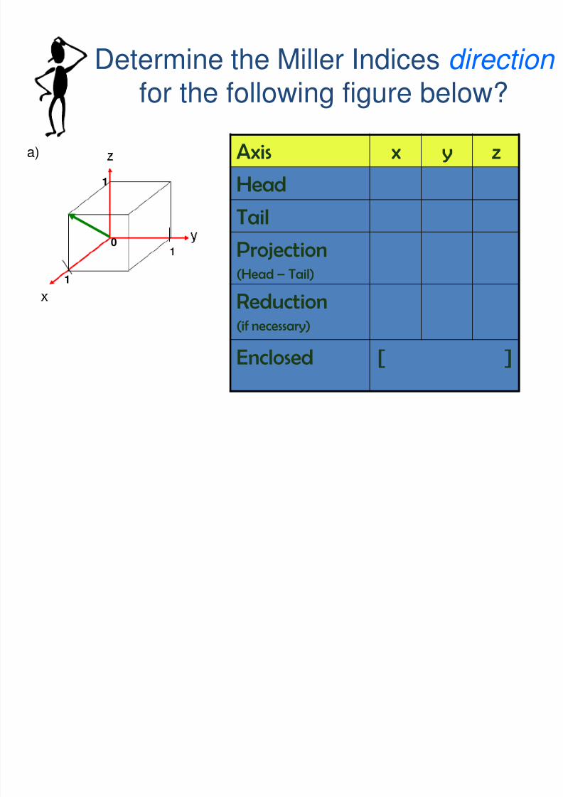
Determine the Miller Indices direction
for the following figure below? a)
Answer :
a) (121)
b) (210)
c) (111)c)
0
1
1
1
Axis x y z
Head
Tail
Projection(Head – Tail)
Reduction(if necessary)
Enclosed [ ]

7/31/2019 Crystal Structure Lec
http://slidepdf.com/reader/full/crystal-structure-lec 44/52
Answer :
a) (121)
b) (210)
c) (111)
b)
0
1
1
1
½
½
Axis x y z
Head
Tail
Projection(Head – Tail)
Reduction(if necessary)
Enclosed [ ]

7/31/2019 Crystal Structure Lec
http://slidepdf.com/reader/full/crystal-structure-lec 45/52
Answer :a) (121)
b) (210)
c) (111) c)
0
1
1
1c) Axis x y z
Head
Tail
Projection
(Head–
Tail)
Reduction(if necessary)
Enclosed [ ]

7/31/2019 Crystal Structure Lec
http://slidepdf.com/reader/full/crystal-structure-lec 46/52
Answer :a) (121)
b) (210)
c) (111) c)
0
1
1
1d) Axis x y z
Head
Tail
Projection
(Head–
Tail)
Reduction(if necessary)
Enclosed [ ]

7/31/2019 Crystal Structure Lec
http://slidepdf.com/reader/full/crystal-structure-lec 47/52
Answer :a) (121)
b) (210)
c) (111) c)
0
1
1
1e) Axis x y z
Head
Tail
Projection
(Head–
Tail)
Reduction(if necessary)
Enclosed [ ]
½
7/31/2019 Crystal Structure Lec
http://slidepdf.com/reader/full/crystal-structure-lec 48/52
Answer :a) (121)
b) (210)
c) (111) c)
0
1
1
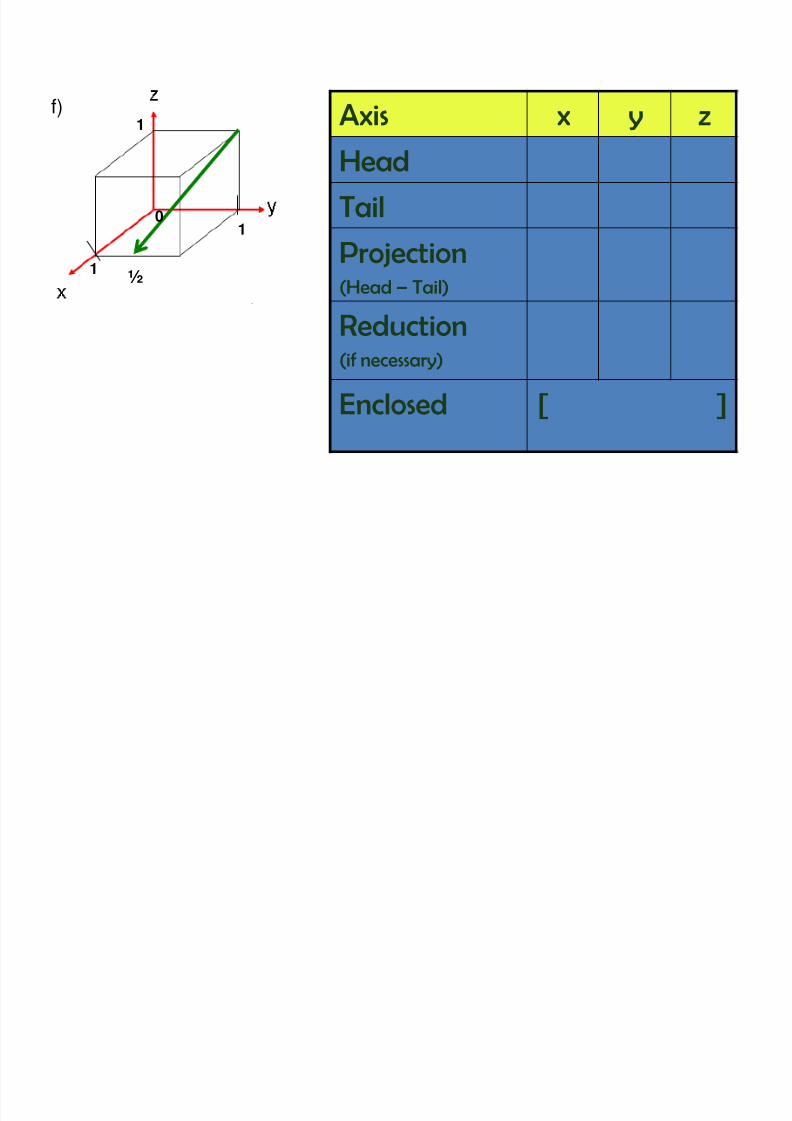
1f) Axis x y z
Head
Tail
Projection
(Head–
Tail)
Reduction(if necessary)
Enclosed [ ]
½

7/31/2019 Crystal Structure Lec
http://slidepdf.com/reader/full/crystal-structure-lec 49/52
Determine the direction indices of the cubicdirection between the position coordinates
TAIL (3/4, 0, 1/4) and HEAD (1/4, 1/2, 1/2)?
Axis x y z
Head
Tail
Projection(Head – Tail)
Reduction(if necessary)
Enclosed [ ]
Answer : [ 2 2 1 ]
7/31/2019 Crystal Structure Lec
http://slidepdf.com/reader/full/crystal-structure-lec 50/52
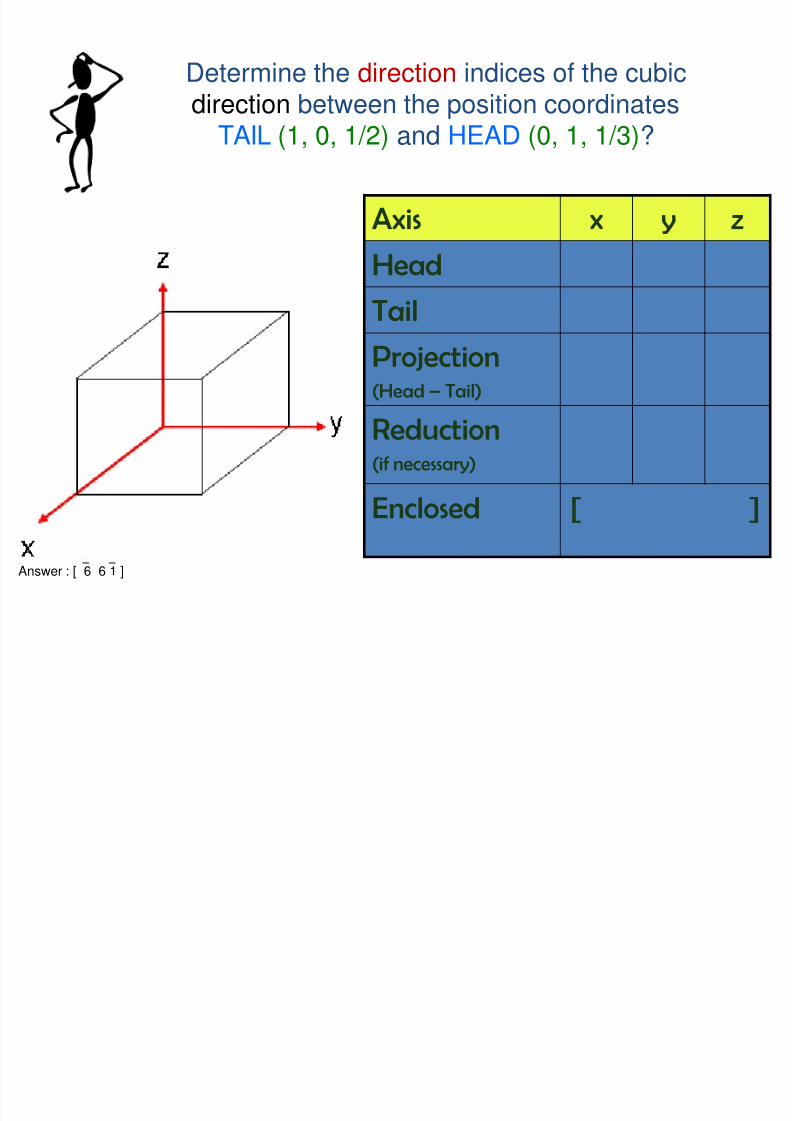
Determine the direction indices of the cubicdirection between the position coordinates
TAIL (1, 0, 1/2) and HEAD (0, 1, 1/3)?
Axis x y z
Head
Tail
Projection(Head – Tail)
Reduction(if necessary)
Enclosed [ ]
Answer : [ 6 6 1 ]

7/31/2019 Crystal Structure Lec
http://slidepdf.com/reader/full/crystal-structure-lec 51/52
Draw the following Miller Indices
direction.
a) [ 1 0 0 ]
b) [ 1 1 1 ]
c) [ 1 1 0 ]
d) [ 1 1 0 ]
e) [ 1 1 2 ]

7/31/2019 Crystal Structure Lec
http://slidepdf.com/reader/full/crystal-structure-lec 52/52
NOTE (for plane and direction):
• PLANE
Make sure you enclosed your final answer in brackets (…) with noseparating commas → (hkl)
• DIRECTION Make sure you enclosed your final answer in brackets (…) with no
separating commas → [hkl]
• FOR BOTH PLANE AND DIRECTION
Negative number should be written as follows :
-1 (WRONG)
1 (CORRECT)
Final answer for labeling the plane and direction should not have fraction number do a reduction.