cw problems and solutions
TRANSCRIPT
8/12/2019 CW Problems and Solutions
http://slidepdf.com/reader/full/cw-problems-and-solutions 1/15
CURTAIN WALL ISSUES, PROBLEMS, AND SOLUTIONS
KARIM P. ALLANA, RRC, RWC, PE; AND DON CARTER
ALLANA BUICK & BERS, I NC . 990 Commercial Street, Palo Alto, CA 94303
Phone: 650-543-5638 • Fax: 650-354-8828 • E-mail: [email protected]
S Y M P O S I U M O N B U I L D I N G E N V E L O P E T E C H N O L O G Y • O C T O B E R 2 01 2 A L L A N A •

8/12/2019 CW Problems and Solutions
http://slidepdf.com/reader/full/cw-problems-and-solutions 2/15
ABSTRACTCurtainwallsare taken for granted, evenby designprofessionals. Allcurtain wall sys-
temsandmaterialspresentuniquechallenges inappearance,design, installation,mainte-
nance, and repair. These issues will be addressed by the presenter with real-life, practicalexamplesbackedbyengineeringexpertise. Theprimaryfocuswillbeglasscurtainwallsandwindowwalls, including failures. Thepresentation isbasedon theauthors’ casestudiesof thefailuresof curtainwalls,windows,sealants,andflashings,providingusefulinformationon design failures and testing. Included are definitions of curtain wall types, various sys-
temsandcomponents,anddifferencesbetweenstickandunitizedcurtainwalls.
SPEAKERK ARIM P. ALLANA, RRC, RWC, PE — ALLANA BUICK & BERS, I NC .
With more than 25 years of experience in construction engineering, forensic investiga-
tion, and design, KARIM ALLANA, RRC, RWC, PE, is CEO and senior principal of AllanaBuick&Bers,Inc.HeearnedhisBSincivilengineeringfromSantaClaraUniversityandisalicensedprofessionalengineerinCalifornia,Hawaii,Nevada,andWashington.Allanahasbeen in the AE and construciton fields for over 30 years, specializing in forensic analysisand sustainable construction of roofing, waterproofing, and the building envelope. He hasactedasaconsultantandexpertwitness in200-plusconstructiondefectprojectsand isafrequentspeakerandpresenteratprofessional forums.
NONPRESENTINGCOAUTHORDON C ARTER — ALLANA BUICK & BERS, I NC .
AseniorcurtainwallconsultantwithAllanaBuick&Bers,DONCARTERhasmorethan45 yearsof experienceintheassessment,design,andconstructionadministrationof store-
front, curtain walls, and glazing systems. Carter was previously a senior consultant withIBA Consultants and worked on the majority of high rises built in the greater Miami areasince1995.Priortothat,hewasatestengineerwithaconstructionresearchlaboratoryandaprojectmanagerwithPermastellisaGroup (formerlyGlassalum International).
9 8 • AL L A N A S Y M P O S I U M O N B U I L D I N G E N V E L O P E T E C H N O L O G Y • O C T O B E R 2 01 2
8/12/2019 CW Problems and Solutions
http://slidepdf.com/reader/full/cw-problems-and-solutions 3/15
Fig e E po ed ie of c ain all componen
CURTAIN WALL ISSUES, PROBLEMS, AND SOLUTIONS
INTRODUCTION Curtainwalldesignandinstallationcan
be taken for granted, even by architects,engineers, and experienced contractors.However,allcurtainwallsystemsandmate-
rials present unique challenges in appear-
ance, design, installation, maintenance,andrepair. Theseissuesandpotentialprob-
lems will be addressed in this paper, withreal-life,practicalexamplesbackedbyengi-
neeringexpertise. Thepaperisbasedontheauthors’ case
studiesof thefailuresof curtainwalls,win-
dows, sealants, and flashings, providinguseful
information
on
design
failures
and
testing. Included are definitions of curtainwall types, various systems and compo-nents, and differences between stick andunitized curtain walls. Included is anoverviewof curtainwalltypes,definitionsof various systems and components, and dif-
ferences between curtain walls, windowwalls,andstorefronts. Testing,designstan-
dards, and the use of mock-ups are woventhroughoutthepresentation.
Curtainwallsconsistof manymaterialsfound in high-rise steel or concrete build-
ingsandeventwo-storywood-framedbuild-ings. Typicalcurtain wall materials includethe following:
• Aluminum extrusions are the load-
bearing element of most moderncurtain wall systems and are avail-
able indifferentalloysasthedesignloadsandsafety factorsrequire.
• Glass(visionandspandrel)• Aluminum panels in sheet, plate or
aluminumcomposites• Stone—typically granite—due to its
superiorresistancetowindloadcom-
paredtomarbleorotherproducts• Glass-fiber-reinforcedconcrete(GFRC)
panels• Louvers• OperablewindowsEach type of curtain wall system or
material presents its own unique appear-
ance, design, installation, maintenance,and repair challenges, to be addressed bythe author. The primary focus will be glass
curtain walls; however,windowwalls,windows,and storefront systemsarealsocovered.
As architectural appealandapplicationshave increased, thecomplexities of dealingwith energy usage dy-
namics, rain and wind,and durability have be-comeevermoredifficultfor the designer. Theauthor reviews the im-
plication
of
different
styles, materials, man-
ufacturers, and instal-lationmethods.DEFINITION AND DESCRIPTION OF CURTAIN WALL SYSTEMS
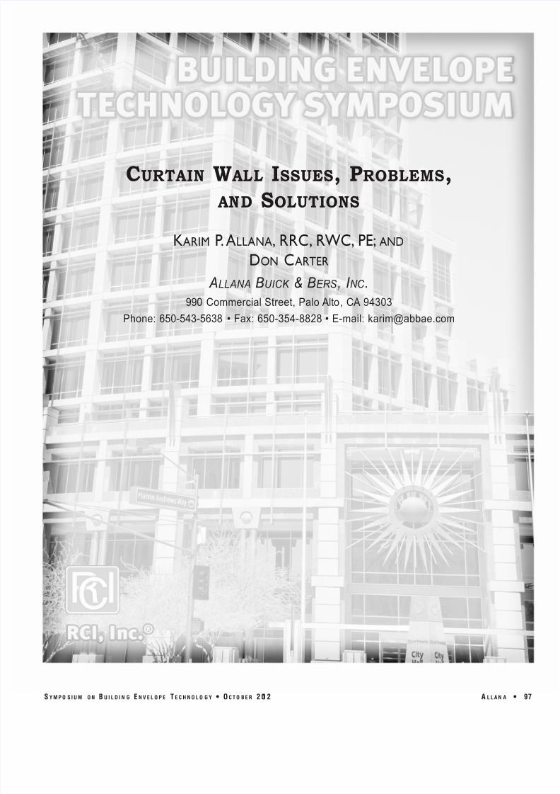
Acurtainwallistheexterior façade of abuilding that 1) spanstwo or more floors inheight; and 2) is non-structural,i.e.,doesnotsupport any loadsexceptforitsowngravi-
ty load, while transfer-
ring wind and other loads to the buildingstructure via connections to each floor,columns, or the roof. Thus, “curtain”impliesthatthewallishungfromthebuild-
ing’sstructural frame,generallytheedgeof theslab.
Curtain walls, as well as other exteriorglazing systems must be properly designedtoaddressthe following:
• Structural integrity• Movement (thermal, seismic, and
differential)• Weathertightness• Condensation• Thermal insulation (curtain walls
only)• Firesafing (curtainwallsonly)Otherproject- orsite-specificconsidera-
ur 1 – x s v w urt w ts. tions such as the following need toaddressed:
• Soundtransmission• Hurricane-bornedebrisresistance
• BombblastresistanceSeeFigure 1.As the curtain wall is mostly nonstru
tural, itcanbemadeof a lightweightmarial, reducing construction costs throustandardization of installation, fast-tra
methods,andreduced loadon thebuildi
frame, leading to lower structural cosAnothergreatadvantage isthatwhengla
isusedasthecurtainwall,naturallightcpenetrate intothebuilding.
Curtain wall frames are commoninfilled with glass but can be infilled w
stone veneer, metal panels, operable ven
S Y M P O S I U M O N B U I L D I N G E N V E L O P E T E C H N O L O G Y • O C T O B E R 2 01 2 A L L A N A •

8/12/2019 CW Problems and Solutions
http://slidepdf.com/reader/full/cw-problems-and-solutions 4/15
Fig e Hallidie b ilding San F anci co C So ce
Wo ld chi ec eMap o g and Wikipedia
Fig e Bole Clo hing Compan b ilding Kan a Ci
MO So ce Wikipedia
ur 2 – y t y u , s s ty,. ur : .
ur 3 – u , r s , . ur : r r t tur . r .
andothercomponents. Today, curtain wall systems are typically designed with extruded
aluminum members, although the first curtain walls were made of steel.THE BASIC GLAZING SYSTEMS CurtainWall
Prefab or assembled units attached to the structure as describedpreviously. Recent improvements in design do not require “dropping”the
building
from
a
swing
stage
to
install
sealants.
Older
designs
required this expensive last step to weatherproofing the joinerybetweenpre-assembledunits.WindowWall
Horizontalbands (ribbons)of fixed/operablewindows,todaymost-
ly factory-assembled and glazed; connected between floors or otherstructuralelementssuchasprecastconcrete.Windows
Individualunits—fixedoroperable—set inawall. Thesearesome-
times referred to as punched windows, connected to studframing,CMU,orprecastconcrete.Storefront
Typicallystick-builtfloortoceiling,includeentrancedoorsandvestibules.Fieldinstalledfromthefloor;framesfirst,thenglass placed in the frame. Note that storefronts may containoperable windows but should not be used at elevations toohigh above the first floor, due to their relatively weak struc-turalcapacity.Notethatamonumentallobbyorentrancewithclear vertical spans over 12 ft. will require a stronger—i.e.,deeper—structuralmember inordertoresistwindloads.BRIEF HISTORY OF CURTAIN WALLS CurtainWallsThroughHistory
Theoldestcurtainwallsconsistedof manydifferenttypesof materials:thickmasonry,brick,terracotta,andwood. Thelimitationonallthesematerialswasweight,seriouslylimitingtheheighttowhichtheycouldbebuilt. Theotherlimitationonthese older types of curtain walls was that not much lightcouldpenetrate.Priortothemiddleof thenineteenthcentury,buildingswereconstructedwiththeexteriorwallsof thebuild-ing,typicallymasonrysupportingtheloadof theentirestruc-
ture. Thedevelopmentandwidespreaduseof structuralsteel(and later, reinforced concrete) allowed relatively smallcolumns to support large loads. Grad-ually, designers wereable todeterminehow todesignexteriorwalls tobenonload-
bearing and thus much lighter and more open. This allowedincreaseduseof glass as anexterior façadeand the modern-daycurtainwall.GlassCurtainWalls intheUnitedStates
ThefirstglasscurtainwallintheUnitedStatesreportedlywasdesignedbythearchitectLouisS.Curtissandinstalledin1909inKansasCityontheBoleyClothingCompanybuilding.
ThatbuildingisnowlistedontheNationalRegisterof HistoricPlacesandisstillinuse (Figure 2 ).
Another building that is sometimes credited as being thefirst glass curtain wall building, the Hallidie building in San
100 • A L L A N A S Y M P O S I U M O N B U I L D I N G E N V E L O P E T E C H N O L O G Y • O C T O B E R 2 01 2
8/12/2019 CW Problems and Solutions
http://slidepdf.com/reader/full/cw-problems-and-solutions 5/15
Fig e To e Ma o b ilding
Me ico Ci So ce Te a ec Inc
Fig e
Le e Ho e
Ne Yo k
Ci So ce
Wikipedia
Fig e
Bell lan
To e
Philadelphi
P So c
Francisco, which was constructed nine yearslaterin1918,isstill inoperationandhouses the Northern California Chapter of the American Institute of Architects (AIA).Although not the first glass curtain wallbuilding,itisagoodexampleof amodernistbuildingwithacurtainwall(Figure 3 ).Notethe steel mullions (vertical members) andother support members. Glasswas typical-
ly
held
in
place
with
clips
and
weather-proofedwithglazingcompound. The first curtain wall installed in New
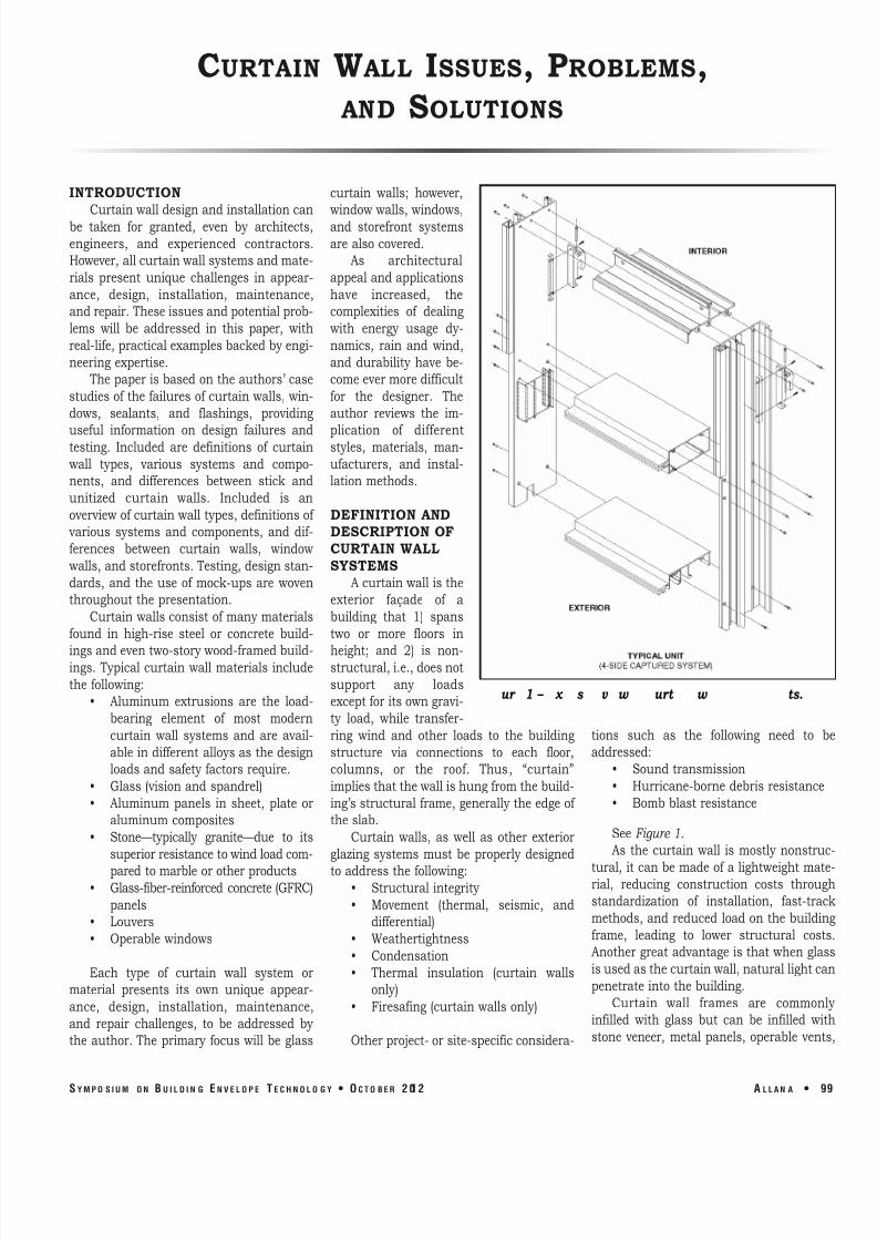
York City, in the Lever House building(Skidmore,Owings,andMerrill,1952),wasa major innovation in the extensive use of steelmullions(Figure 4 ).
In the 1960s, there was the first wide-
spread use of aluminum extrusions forload-bearingmullions.Aluminumofferstheuniqueadvantageof beingable tobeeasilyextrudedintonearlyanyshaperequiredfordesign and aesthetic purposes. Customshapes can be designed and manufacturedwith relative ease, although each newdesign brings new complexities in installa-
tion, testing, and maintenance, discussedlaterinthisarticle.Granite-CladCurtainWalls intheU.S.
Figure 5 depicts the Bell Atlantic TowerinPhiladelphia,cladinglassand65%gran-
ite. The stone for this 500,000-sq.-ft. cur-tain wall was quarried in Sweden, thenshipped in blocks to Italy, where it wasfabricated into 3-cm-thick infill panelswithpolished,honed,andflamedfinish-es. Thegranitepanelswerethenshippedto Miami, installed into 10,500 unitizedpanels, and shipped to Philadelphia byflatbed trailers, where floors 3 through42 were wrapped in curtain wall at therateof twofloorsperweek.OtherCurtainWallsAroundtheWorld
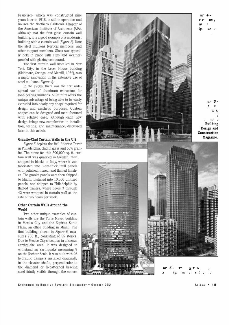
Two other unique examples of cur-
tain walls are the Torre Mayor buildingin Mexico City and the Espirito SantoPlaza, an office building in Miami. Thefirst building, shown in Figure 6 , mea-
sures 738 ft., consisting of 55 stories.DuetoMexicoCity’slocationinaknownearthquake area, it was designed towithstand an earthquake measuring 9ontheRichterScale.Itwasbuiltwith96hydraulic dampers installed diagonallyin the elevator shafts, perpendicular tothe diamond or X-patterned bracingsteel faintly visible through the convex ur 6 – rr y r u ,
x ty. ur : r t , .
ur 4 – v r us w r ty. ur
.
ur 5
t w
. ur Buildi
DesignaConstructi
Magazin
S Y M P O S I U M O N B U I L D I N G E N V E L O P E T E C H N O L O G Y • O C T O B E R 2 01 2 A L L A N A • 1

8/12/2019 CW Problems and Solutions
http://slidepdf.com/reader/full/cw-problems-and-solutions 6/15
Fig e E pi i o San o B ilding Miami No e
conical hape and comple i of b ilding face
So ce Vi acon Inc
Fig e S ick a embl nde con c ion
ur 7 – s r t t u , . t s x ty u .
ur : r , .
steel sections—highly sus-
ceptible to rust—was aban-
doned in favor of tubularaluminum extrusions. Notonly is aluminum “rust-
proof,” it can be easilyextruded into more complexshapesthanwouldbepossi-
blewith steel. The improvedweatherability
of
aluminum,
combinedwiththisabilitytoaddress complex architec-tural detailing, has made itthematerialof choicetoday.SeeFigure 8 .
Stick system assembliestend to be a more attractivesystem for smaller two- tothree-story jobs becausedelivery is quicker and thesystems are more afford-
able. Installers need to takeinto consideration that allthe critical joints are sealedat the jobsite and may besubject to dirt, wind, andother environmental conta-
minants.However, therearefaçade in Figure 6 . In January 2003, a 7.6magnitude earthquake shook Mexico City,but the building was not damaged, andmany occupants were unaware of thequake. This curtain wall provided designchallenges due to sloped and reverse-slopeglazing and the building face curvature,achievedwithsegmentedpanels.
Figure 7 isaphotoof theEspiritoSantoBuilding, the 36-story Miami building, thearchitecture of which is based loosely onthe Saint Louis Arch. Design and installa-
tion challenges faced in this building alsoincludedslopedglazing, theconical façade,hundredsof customextrusions,averylargenumber of complicated construction de-tails, thousands of fabrication documentsheets, and extensive laboratory testing,including large- and small-missile impact.Designwind loadsforthecurtainwallwere+140/-180 psf. The design and construc-
tionof thisbuildingwasaidedby3-Dmod-
eling.TYPES OF CURTAIN WALL SYSTEMS StickSystems
Theoriginalglasscurtainwallstructur-
al framing was hot-rolled steel sections,erected in piece-by-piece fashion or in“sticks.” As noted previously, the use of
some disadvantages to thestick-builtinstallationof curtainwalls:
• Thermalmovement joints. Themainload-bearing vertical mullions arenormally installed in lengths span-
ning two floors, with splice jointsnecessarily occurring in the glazed
areas—typically the spandrel glaz-
ing. On a typical 2.5-in. system,glazedwithinsulatedglass,theedge-clearancerequirementsfortheglass,plus frame fabricationtoleranceandglass size tolerance, translate into amaximum 0.5-in. splice joint. Whenthe +50% movement capacity of thesilicone sealant in the joint is fac-
toredinto
the
equation,
the
resulting
totalmovementthatthe0.5-in. jointcan accommodate is +0.25 inch.
Thus, for this 2.5-in.-face-dimen-
sion, off-the-shelf standard system(spanning two 12.5-ft. floors, withthermal expansion and contractionat the industry-standard 180ºF sur-
facetemperature),thethermalmove-
ment is approximately 0.1875 of aninch,leavingonly .0625 in. forothertolerances, such as fabrication anderection.
• Differential floor live-load deflec-tions/axial shortening of steelcolumnsonhighrisesduetogravityload,or long-termcreepof high-riseconcrete structures due to sus-
tainedgravityloads. Thetypical2.5-
in. face dimension standard sys-tems, as demonstrated above, can-
not factorthesemovements intothe0.5-in. thermal expansion joint every25ft. Theseaddedmovementsare generally calculated by thestructural engineer to fall between
Expansion Joints
ur 8 – t ss y u r stru t .
1 02 • A L L A N A S Y M P O S I U M O N B U I L D I N G E N V E L O P E T E C H N O L O G Y • O C T O B E R 2 01 2
8/12/2019 CW Problems and Solutions
http://slidepdf.com/reader/full/cw-problems-and-solutions 7/15
Fig e Uni ized mod la con c ion
Fig e M llion de ail
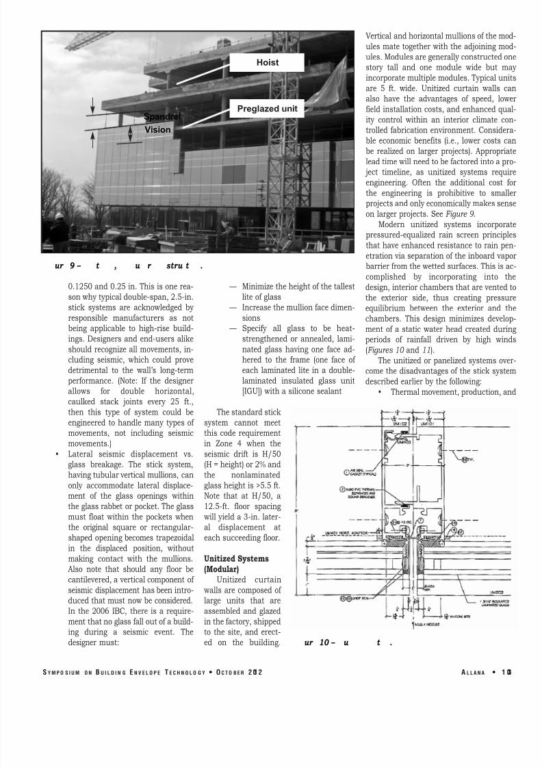
Preglazed unit
Hoist
Spandrel Vision
ur
9 –
t
,
u r
stru t
.
0.1250and0.25 in. This isonerea-
sonwhytypicaldouble-span,2.5-in.stick systems are acknowledged byresponsible manufacturers as notbeing applicable to high-rise build-
ings. Designers and end-users alikeshouldrecognizeallmovements, in-cluding seismic, which could provedetrimental to the wall’s long-termperformance. (Note: If the designerallows for double horizontal,caulked stack joints every 25 ft.,then this type of system could beengineered to handle many types of movements, not including seismicmovements.)
• Lateral seismic displacement vs.glass breakage. The stick system,havingtubularverticalmullions,canonly accommodate lateral displace-ment of the glass openings withintheglassrabbetorpocket. Theglassmust float within the pockets whenthe original square or rectangular-
shapedopeningbecomestrapezoidalin the displaced position, withoutmaking contact with the mullions.Also note that should any floor becantilevered,averticalcomponentof seismicdisplacementhasbeenintro-ducedthatmustnowbeconsidered.In the 2006 IBC, there is a require-
mentthatnoglassfalloutof abuild-ing during a seismic event. Thedesignermust:
— Minimizetheheightof thetallestliteof glass
— Increasethemullionfacedimen-
sions — Specify all glass to be heat-
strengthened or annealed, lami-
nated glass having one face ad-hered to the frame (one face of each laminated lite in a double-
laminated insulated glass unit[IGU])withasiliconesealant
Thestandardsticksystem cannot meetthis code requirementin Zone 4 when theseismic drift is H/50(H=height)or2%andthe nonlaminatedglassheightis>5.5ft.Note that at H/50, a12.5-ft. floor spacingwill yielda3-in. later-al displacement ateachsucceeding floor.UnitizedSystems(Modular)
Unitized curtainwalls arecomposedof large units that areassembled and glazedinthefactory,shippedto the site, and erect-
ed on the building. ur 10 – u t .
Verticalandhorizontalmullionsof themo
ulesmate togetherwiththeadjoiningmo
ules.Modulesaregenerallyconstructedostory tall and one module wide but m
incorporatemultiplemodules. Typicalun
are 5 ft. wide. Unitized curtain walls calso have the advantages of speed, low
field installationcosts,andenhancedqu
ity control within an interior climate co
trolledfabrication
environment.
Consideble economic benefits (i.e., lower costs c
be realized on larger projects). Appropria
leadtimewillneedtobefactoredintoap ject timeline, as unitized systems requ
engineering. Often the additional costthe engineering is prohibitive to smalprojectsandonlyeconomicallymakessen
on largerprojects.SeeFigure 9 .Modern unitized systems incorpora
pressured-equalized rain screen princip
thathave enhancedresistance torainpe
etrationviaseparationof theinboardvap
barrierfromthewettedsurfaces. Thisisacomplished by incorporating into t
design,interiorchambersthatarevented
the exterior side, thus creating pressuequilibrium between the exterior and t
chambers. This design minimizes develo
ment of a static water head created duriperiods of rainfall driven by high win
(Figures 10 and11). Theunitized or panelizedsystemsov
comethedisadvantagesof thesticksyste
describedearlierbythe following:• Thermalmovement,production,a
S Y M P O S I U M O N B U I L D I N G E N V E L O P E T E C H N O L O G Y • O C T O B E R 2 01 2 A L L A N A • 1

8/12/2019 CW Problems and Solutions
http://slidepdf.com/reader/full/cw-problems-and-solutions 8/15
Fig e S ackjoin de ail
Fig e ncho de ail No e Thi p ojec did no eq i e a pocke on op
of lab d e o comp e floo ing and he lab in e a c om made
ur
11 –
t
t t .
erection tolerances, differential floor deflections, and columnshortening/long-termcreeparealladdressedindimensioningthestack
joint
(i.e.,
the
joint
on
each
floor
where
the
upper
unit
is
stackedatopthe lowerunit). (SeeFigure 11.)
• Seismicdisplacementisaddressedviathetippingmotionof adja-centunitsas the two-piecemaleand femalematingverticalmul-
lions slide vertically, relative to each other, as the floor abovemovesleft/rightrelativetothefloorbelow.Usingedgeblockinginthe vertical glazing rabbets (glass to aluminum) enables theunits/panelstoretaintheirrectangularshapeandpreventsedge-
of-glasscontactwith the frame. Thisretentionof theglasswithin theopening is furtherenhancedif theperimeterof eachliteisfullyadheredtotheframe with structural silicone adhesive. (SeeFigures 10 and11.)
ur 12 – r t . ( t : s r t t r u r t t s u t ut r r , t s s rt w s ust - .)
1 04 • A L L A N A S Y M P O S I U M O N
Lock Bolt MOUNTING AND INSTALLATION Stick-AssemblyCurtainWalls
Verticalmullionsspanningtwofloorsaretyp-
ically anchored with steel or aluminum clipangles mounted on the face of the slab by weld-ing to a hot-rolled screed angle or by expansionbolts/epoxy bolts into reinforced concrete. Thedead load/wind loadanchorhas horizontalslotsfor adjusting the mullion cantilever in and out,whilethewind-load-onlyanchorhasverticalslotsto bolt the mullion with slip pads to allow forthermalmovement.Embedded“Halfen”channelsortubescastintotheslabcanreplaceweldingorfieldhammerdrillingof theslab.UnitizedCurtainWalls
Typical connections are to the top of a slabcastwitharecessedpocketandHalfenembeddedinserts. An extruded aluminum or formed-steelangle plate is then bolted to the insert and can-
tilevered off the slab, toed up to engage with amating anchor bolted to each side of the units.
The mating frame-hook anchors contain jack
B U I L D I N G E N V E L O P E T E C H N O L O G Y • O C T O B E R 2 01 2
8/12/2019 CW Problems and Solutions
http://slidepdf.com/reader/full/cw-problems-and-solutions 9/15
Fig e Windo all ill de ail
Fig e The mal epa a o de ail
bolts used to raise the units to the correctelevation. The bottom of each unit nestswithintheheadof thelowerunit,andalockboltisusedsotheunitsdonot“walk”afterinstallation. In all applications—stick orunitized—curtain walls must be can-tileveredoutboardof theslabtoallowroomforAISCorACItolerancesforsteelandcon-
crete erection, plus differences in as-builtfloor
registration,
one
above
the
next.
To
accommodate this buildup of clearances, itisnotuncommontodesignclearancesfromthe back of the mullion to the face of theslabof 2.5 in.,+/-1.5 in. (Figure 12 ).WindowWall
Thishorizontalribbonof fixedoropera-
ble windows is always connected betweenslabs or other construction such as studframing,CMU,precast,orGFRC. Thewind-
loadtransferoccursateachendof thever-
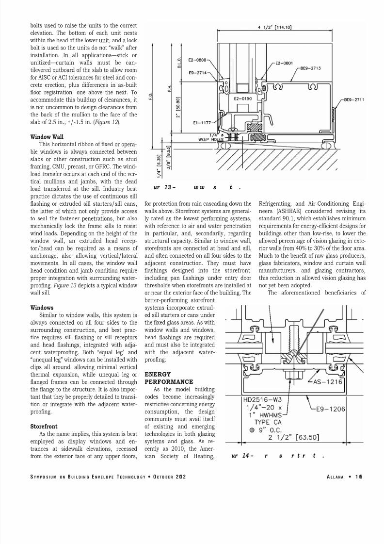
tical mullions and jambs, with the deadload transferred at the sill. Industry bestpractice dictates the use of continuous sillflashing or extruded sill starters/sill cans,the latter of which not only provide accessto seal the fastener penetrations, but alsomechanically lock the frame sills to resistwind loads. Depending on theheight of thewindow wall, an extruded head recep-
tor/head can be required as a means of anchorage, also allowing vertical/lateralmovements. In all cases, the window wallhead condition and jamb condition requireproper integration with surrounding water-
proofing.Figure 13 depictsatypicalwindowwallsill.Windows
Similar to window walls, this system isalways connected on all four sides to thesurrounding construction, and best prac-tice requires sill flashing or sill receptorsand head flashings, integrated with adja-
cent waterproofing. Both “equal leg” and“unequalleg”windowscanbeinstalledwithclips all around, allowing minimal verticalthermal expansion, while unequal leg orflanged frames can be connected throughthe flangetothestructure.Itisalso impor-
tantthattheybeproperlydetailedtotransi-
tion or integrate with the adjacent water-proofing.Storefront
Asthenameimplies,thissystemisbestemployed as display windows and en-
trances at sidewalk elevations, recessedfrom the exterior face of any upper floors,
ur
13 –
w w
s
t .
forprotectionfromraincascadingdownthewallsabove.Storefrontsystemsaregeneral-ly rated as the lowest performing systems,with reference to air and water penetrationin particular, and, secondarily, regardingstructuralcapacity.Similartowindowwall,storefronts are connected at head and sill,andoftenconnectedonallfoursidestotheadjacent construction. They must haveflashings designed into the storefront,including pan flashings under entry doorthresholdswhenstorefrontsareinstalledatorneartheexteriorfaceof thebuilding. Thebetter-performing storefrontsystems incorporate extrud-edsillstartersorcansunderthefixedglassareas.Aswithwindow walls and windows,head flashings are requiredand must also be integratedwith the adjacent water-
proofing.ENERGY PERFORMANCE
As the model buildingcodes become increasinglyrestrictiveconcerningenergyconsumption, the designcommunity must avail itself of existing and emergingtechnologies in both glazingsystems and glass. As re-
cently as 2010, the Amer-
ican Society of Heating,
Refrigerating, and Air-Conditioning En
neers (ASHRAE) considered revisingstandard90.1,whichestablishesminimu
requirementsforenergy-efficientdesignsbuildings other than low-rise, to lower t
allowedpercentageof visionglazinginexriorwallsfrom40%to30%of thefloorar
Muchtothebenefitof raw-glassproduce
glass fabricators, window and curtain wmanufacturers, and glazing contracto
thisreduction inallowedvisionglazingh
not yetbeenadopted. The aforementioned beneficiaries
ur 14 – r s r t r t .
S Y M P O S I U M O N B U I L D I N G E N V E L O P E T E C H N O L O G Y • O C T O B E R 2 01 2 A L L A N A • 1
8/12/2019 CW Problems and Solutions
http://slidepdf.com/reader/full/cw-problems-and-solutions 10/15
ASHRAE’s failuretoacthadbeen, forquitesome time, aggressively investing in newtechnologies toreduceenergyconsumptioninnewconstruction.Inglazing,forexample,
• Triple-pane insulatingglass• Low-E (low emissivity) coatings on
oneormoresurfacesof an IGU• Argonandkryptongas-filled IGUs• Warm-edgespacers in IGUS• ElectronicallytintableglassForgenerationof electricity• Photovoltaicglassunits (PVGU)Forthealuminumframing• Thermal separators such as PVC or
elastomericgaskets(Figure 14 )• Poured and debridged polyurethane
thermalbreaks(Figure 15 )• Glass-reinforced polyamide thermal
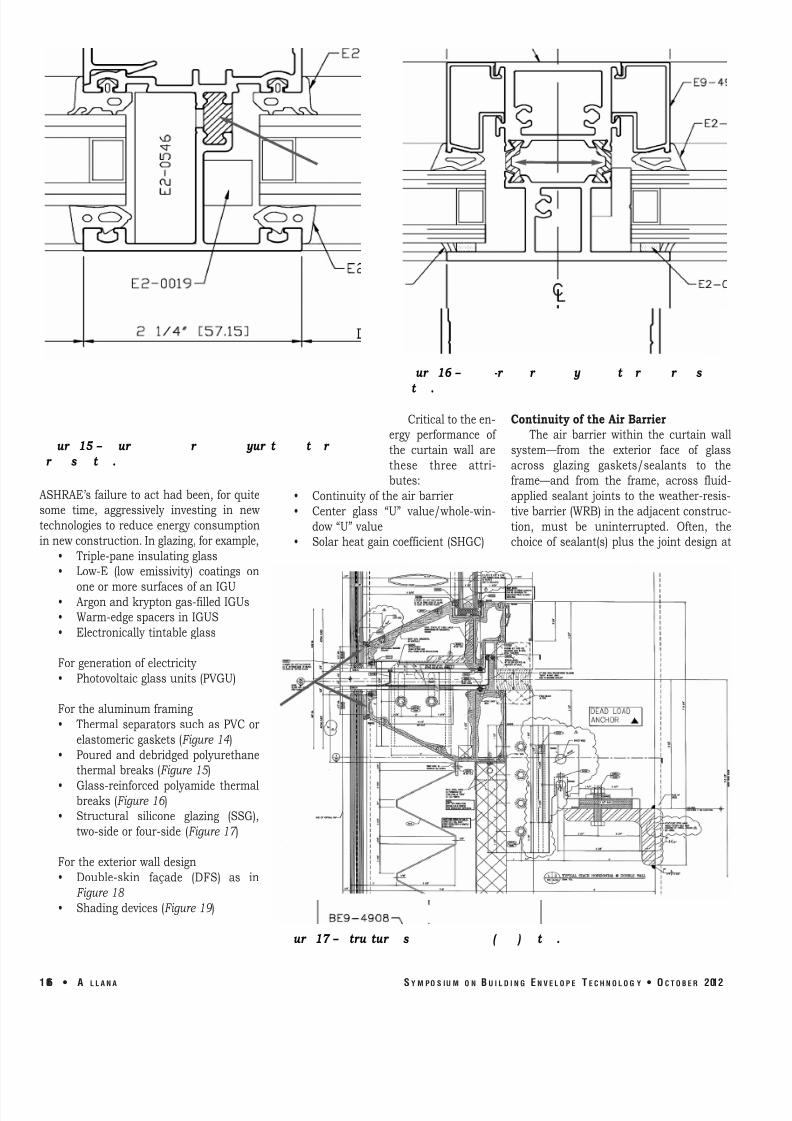
breaks (Figure 16 )• Structural silicone glazing (SSG),
two-sideor four-side (Figure 17 )Fortheexteriorwalldesign• Double-skin façade (DFS) as in
Figure 18 • Shadingdevices (Figure 19 )
Criticaltotheen-ergy performance of the curtain wall arethese three attri-butes:
• Continuityof theairbarrier• Center glass “U” value/whole-win-
dow“U”value• Solarheatgaincoefficient (SHGC)
Continuityof theAirBarrier The air barrier within the curtain wall
system—from the exterior face of glassacross glazing gaskets/sealants to theframe—and from the frame, across fluid-
applied sealant joints to the weather-resis-
tivebarrier(WRB)intheadjacentconstruc-
tion, must be uninterrupted. Often, thechoice of sealant(s) plus the joint design at
1 06 • A L L A N A S Y M P O S I U M O N B U I L D I N G E N V E L O P E T E C H N O L O G Y • O C T O B E R 2 01 2
ur 15 – ur r yur t t r r s t .Fig e Po ed and deb idged pol e hane he mal
b eak de ail
Fig e Glaze einfo ced pol amide he mal b eak
de ail
Fig e S c al ilicone glazing SSG de ail
ur 16 – -r r y t r r s t .
ur 17 – tru tur s ( ) t .

8/12/2019 CW Problems and Solutions
http://slidepdf.com/reader/full/cw-problems-and-solutions 11/15
the perimeter of all glazing systems is notgiven the proper consideration. The archi-
tect,inthesealantsspecification,willsome-
times specify a one- or two-part polyure-
thanesealant forthis joint,notrealizing• Polyurethane will not adhere to sili-
cone sealants, which are the mostcommon frame joint sealants in theglazing industry,and
• Polyurethanedegradesquicklywhen
exposedtoUVrays. The forces this joint must withstand in
compression,extension,andsheararealsofrequently overlooked in the architect’sperimetercaulk-jointdesigns.Inthecaseof open-backhorizontalheadmembers and tubular vertical membersrunning through the head members, thesehollows don’t work with preengineered
assemblies. The integration of engineertransitionassemblies isbestusedwith fatory-assembled aluminum/vinyl windo
having mitered corners. It is more diffic
to implement with hollow aluminum extr
sionsand/oropen-backextrusionswithothe contractor-installing sealed enclosur
intheendsof thetubes. Thesealantsneedtobecompatiblew
theWRB.Inmanycases,theWRBadjace
to the fenestration isbest installedwithaluminum foil-faced peal-and-stick me
brane;thatway,therearenoworriesabo
compatibility issues between the perimesealantandthe foiled-facedWRB.CenterGlassUValue/WholeWindowUValue
Thepast20 yearshavemarkedanexpnential improvement in glass technolo
Metrics such as U value, whole-windowvalue,andothersarenowcommonterms
specifying glazing. The rate of heat lo
through glass is termed center-of-glassvalue or factor, and the lower the U fact
the greater the glass’s resistance to he
flow. There are now double-pane IGavailable with low E coatings on both li
and argon-gas-filled with center-of-glass
S Y M P O S I U M O N B U I L D I N G E N V E L O P E T E C H N O L O G Y • O C T O B E R 2 01 2 A L L A N A • 1
ur 19 – v .ig e Shading de ice
Fig e Do ble kin façade b ffe façade e ac ai façade in face façadeur 18 – u -s : u r , xtr t r tw - .
8/12/2019 CW Problems and Solutions
http://slidepdf.com/reader/full/cw-problems-and-solutions 12/15
Fig e Sealan fail e be een p eca c ain
all
values as low as 0.20 or R-5. For whole-
window “U” value, including glass andframe, the National Fenestration RatingCouncil (NFRC)hasdevelopedaprocedure,NFRC100,fordeterminingthe fenestrationproduct U value. This whole-window Uvalue is commonly higher than the center-
of-glass U value. A high-performance, dou-
ble-glazed window can have U values of 0.30
or
lower.
As
the
description
of
U
value
implies,lowUvaluesaremostimportantinheating-dominated climates, although theyarealsobeneficial incooling-dominatedcli-
mates.SolarHeat-GainCoefficient (SHGC)
Solarheatgaincoefficient (SHGC) isthefraction of incident solar radiation passingthroughawindow,bothdirectlytransmittedand absorbed, then released inward. SHGCisexpressedasanumberbetween0and1.
The lower theSHGCof awindowassembly,the lesssolarheat it transmits. Thenation-ally recognized SHGC rating method is theNFRC200procedure fordetermining fenes-tration product solar heat gain coefficientand visible transmittance at normal inci-
dence. Whole-window SHGC is lower thanglassonlySHGC,andisgenerallybelow0.7.While solar heat gain can provide free heatin winter, it can also lead to overheating insummer. To best balance solar heat gainwith an appropriate SHGC, the designermust consider climate, orientation, shadingconditions,andotherfactors.CURTAIN WALL TEST PROCEDURES
Testingcanoccuratvariousstagesof aproject, includingpreconstructionmock-upstagesandforensicinvestigationsforpossi-
ble defect analysis. The curtain wall testproceduresoutlined inthissectionare lab-
oratory performance testing and not field-
testingproceduresforinstalledfenestrationsystems. There is a wide array of testingprocedures available to the designer andinstaller, includingthe following.AirInfiltration – ASTME283
Staticpressuretesttomeasureairinfil-
trationthroughthespecimenbyevacuatingair from the test chamber, typically mea-
suredat6.24psf.forarchitecturalproductsand 1.57 psf. forone- to two-storyresiden-tial. The maximum allowed industry stan-
dard for architectural fixed glazing is 0.06cfmat6.24psf.
StaticWaterInfiltration – ASTME331Static pressure test to determine leak
resistance through the specimen by spray-ing water at a uniform rate of 5 gals./hr./sq.ft.,whilesimultaneouslyevacuatingairfromthetestchamberatthespecifiedwatertest pressure (WTP). Typically, the WTP isspecifiedat20%of thepositivedesignwindload, but not less than 6.24 psf. (defaultpressure
for
architectural
rated
systems
and 2.86 psf. for residential systems).Allana Buick & Bers recommends WTP at20% (recommended by AAMA) of positivedesignwindpressure(Pd),butnotlessthan12 psf. (for any curtain wall taller than tenfloors).DynamicWaterInfiltration – AAMA501.1
Dynamic test using the same rate of water delivery in ASTM E331 but using anaircraftenginetoprovidereal-worldpositivepressure to the specimen’s exterior. WTPdetermined inthesamemannerasabove.StructuralTesting – ASTME330
1. Testing via static air pressure atboth the (+) and (-) Pd while mea-
suring frame and glass deflections.Industry standarddeflection limitsa. For spans up to
12.5 ft.=L/175b. For spans >12.5
ft. and up to 40ft.=L/240+0.25
c. For glass = 1.0 in. (NOTE: In h i g h - v e l o c i t y hurricane zones [HVHZ]), this limit does not apply, provided the glass strength analysis performed per ASTM E1300 proves that the probability of breakage due to wind pressure doesnotexceed8 lts/1000 for ver-
tical glazing and sloped glazing ≤15 degrees from vertical; for sloped glazing >15 degrees from
vertical,theprobabilityof break-
agemaynotexceed1 lt/1000.2. After passing the structural tests at
Pd, the specimens must pass thetest or proof load that provides thissafety factor:a. For vertical glazing and sloped
glazing ≤15 degrees from verti-
cal,Pd ismultipliedby1.5.b.
For
sloped
glazing
>15
degrees,
Pdismultipliedby2.0.
c. Deflections are not recorded,and the specimens pass whenthere is no glass breakage andthe permanent set (deformation)is≤0.2%of span forarchitectur-al products and ≤0.4% for resi-
dentialproducts.d. Sloped glazing in areas subject
to snow accumulation musthave the wind pressure Pd in-
creased by a factor representingexpectedsnow load.e. Seismic or Wind-induced Inter-
story Drift – AAMA501.4 – Statictestmethodfocusesprimarilyonchanges in serviceability of thespecimen after horizontal rack-
ing at the design displacement
ur 20 – t ur tw r st/ urt w .
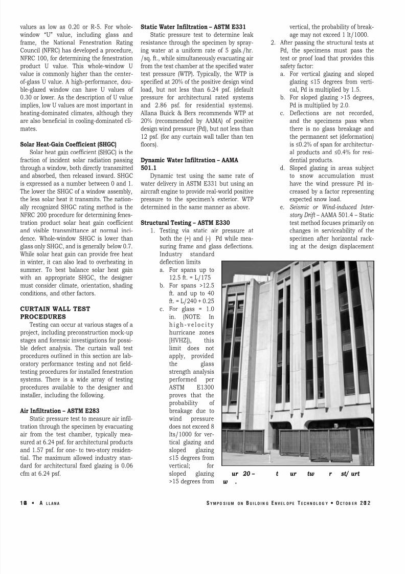
1 08 • A L L A N A S Y M P O S I U M O N B U I L D I N G E N V E L O P E T E C H N O L O G Y • O C T O B E R 2 01 2
8/12/2019 CW Problems and Solutions
http://slidepdf.com/reader/full/cw-problems-and-solutions 13/15
Fig e Sealan join id h oo na o
o handle hea in ealan
Fig e Segmen ed indo all
Fig e P ec ed eala
can handle e en io
ur 21 – t t w t t rr w t s r s t.
ur 22 – r ur s 200% xt s
(Dp), after which the specimen is subjected to repeat air and water tests. Then, after the “proof” test at 1.5 Pd, 501.4 is repeated at 1.5 Dp. Pass/fail criteria are dependent upon the building’s use and occu-
pancy. OtherTests
1. AAMA 501.5 – Ther mal Cycling
2. AAMA 501.6 – Seismic Drift CausingGlassFallout
3. AAMA 501.7 – Vertical SeismicDisplacement
4. ASTM E1886 and E1996 – Large and Small Missile ImpactandCycling
5. Blastresistance6. Window-washing tie-back
loadtest FORENSIC CASE STUDIES SealantFailures
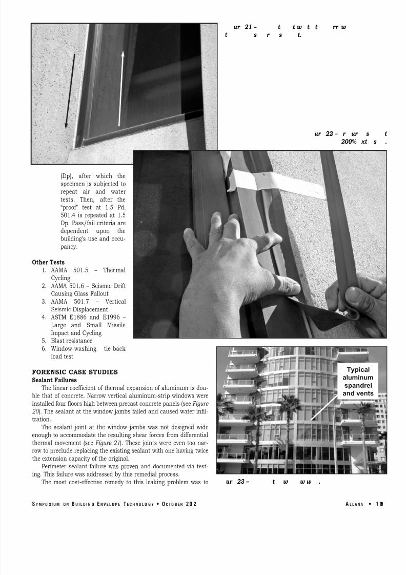
The linearcoefficientof thermalexpansionof aluminum isdou-ble that of concrete. Narrow vertical aluminum-strip windows wereinstalledfourfloorshighbetweenprecastconcretepanels(seeFigure 20 ). Thesealantat thewindow jambs failedand caused water infil-tration.
The sealant joint at the window jambs was not designed wideenough to accommodate the resulting shear forces from differentialthermal movement (see Figure 21). These joints were even too nar-rowtoprecludereplacingtheexistingsealantwithonehavingtwicetheextensioncapacityof theoriginal.
Perimeter sealant failure was proven and documented via test-ing. This failurewasaddressedbythisremedialprocess.
The most cost-effective remedy to this leaking problem was to
Typical aluminum spandrel and vents
ur 23 – t w w w .
S Y M P O S I U M O N B U I L D I N G E N V E L O P E T E C H N O L O G Y • O C T O B E R 2 01 2 A L L A N A • 1

8/12/2019 CW Problems and Solutions
http://slidepdf.com/reader/full/cw-problems-and-solutions 14/15
Fig e Windo all de ail
Fig e In e io a e leak damage
Fig e B In e io a e leak damage
ur 24 – w w t .
ur 25 – t r r w t r- .
ur 25 – t r r w t r- .
overlaythefailedsealantwithprecuredsili-
cone with at least four times the extensioncapacity of the original sealant (see Figure 22 ). One half inch of each edge of the pre-
cured silicone was adhered to the alu-
minumandconcretewithsiliconesealant.Failureof WindowWallSystem
The segmented (chorded in plan) win-
dow
wall
was
unitized
and
installed
from
the building interior (Figure 23 ). Like allwindow walls, it was anchored betweenother construction—floor slabs in thiscase—but the bottom 8 to 10 in. werenotched vertically to permit the remaining2.5-in.exteriorportiontobypassthefaceof slab, terminating with a sealant joint against the outboard cantilevered headreceptor of the window wall on the floorbelow (Figure 24 ).
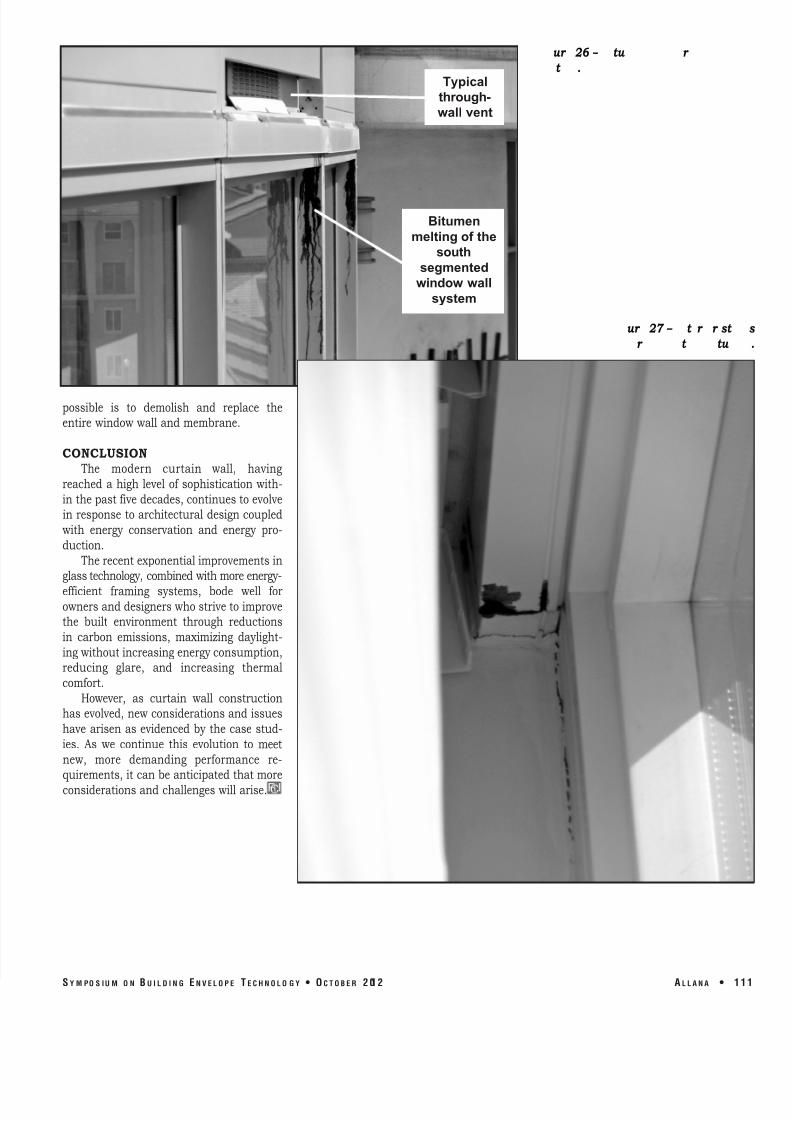
Evidence of water penetration (Figure 25 ) was subsequently proven to occur byASTM E1105 water testing. The most diffi-cult problem to remedy was the ongoingslowdissolvingof thebitumencontainedinthe waterproofing membrane (Figures 26 and27 ). Thisproblemwastracedtochemi-
cal incompatibilitybetween thewaterproof-
ing membrane and lap sealants/head receptorperimetersealant.Duetotheover-
lapping shingle design of the window wallabove and outboard the membrane (referback to Figure 24 ), the only remediation
1 10 • A L L A N A S Y M P O S I U M O N B U I L D I N G E N V E L O P E T E C H N O L O G Y • O C T O B E R 2 01 2
8/12/2019 CW Problems and Solutions
http://slidepdf.com/reader/full/cw-problems-and-solutions 15/15
Fig e Bi men memb ane
mel ing
Fig e In e io ai
f om mel ing bi me
possible is to demolish and replace theentirewindowwallandmembrane.CONCLUSION
The modern curtain wall, havingreached a high level of sophistication with-
inthepastfivedecades,continuestoevolveinresponse toarchitecturaldesigncoupledwith energy conservation and energy pro-
duction. Therecentexponentialimprovementsin
glasstechnology,combinedwithmoreenergy-
efficient framing systems, bode well forownersanddesignerswhostrivetoimprovethe built environment through reductionsin carbon emissions, maximizing daylight-
ingwithoutincreasingenergyconsumption,reducing glare, and increasing thermalcomfort.
However, as curtain wall constructionhasevolved,newconsiderationsandissueshave arisen as evidenced by the case stud-
ies. As we continue this evolution to meetnew, more demanding performance re-quirements,itcanbeanticipatedthatmoreconsiderationsandchallengeswillarise.
ur 26 – tu r t .
ur 27 – t r r st r t tu
Typical through-
wall vent
Bitumen melting of the
south segmented window wall
system