d d hyperdrive gen4 12 cell 44v modular pack
TRANSCRIPT

A A
B B
C C
D D
E E
F F
1
1
2
2
3
3
4
4
5
5
6
6
7
7
8
8
A3
Scale:
Part Number:
Size A3: 297 mm x 420 mm
Title:
Originator:
Checked By:
Approved By:
Material:
Weight:
Sheet: of
The information contained in this
drawing is the sole property of
Hyperdrive Innovation Ltd. It must not be
reproduced in part or whole without
the express permission of
Hyperdrive Innovation Ltd.
Hyperdrive Innovation Ltd. The Future Technology Centre,
Barmston Court, Nissan Way, Sunderland, Tyne & Wear
SR5 3NY
Tel: +44 (0) 191 6404586
Web: hyperdriveinnovation.com
HYP-00-2889 Product Information
HYP-00-2889
MC
JL
SF
07/05/2019
MIXED
07/05/2019
07/05/2019
DNS
1 4
Dimension:
Millimetre (mm)
THIRD ANGLE
PROJECTION
GENERAL TOLERANCES ACCORDING TO ISO 2768
DIMENSION
TOLERANCE (mm)
ref. ISO 2768-1
GEOMETRIC
TOLERANCE (mm)
ref. ISO 2768-2
LENGTH (mm) CHAMFERS (mm) ANGLE (DMS)
STRAIGHTNESS
& FLATNESS (mm)
PERPENDICULARITY
(mm)
SYMMETRY (mm)
CLASS: m CLASS: m CLASS: m
CLASS: K CLASS: K CLASS: K
Drawing Number:
HYP-INF-2889
Revision:
R7
REVISION HISTORY
REV DESCRIPTION ORIGINATOR CHECKED BY APPROVED DATE
R1-R6 PLEASE REFER TO HYP-226-BOM-Z-005 FOR REV CHANGE DETAILS MC JL SF
07/05/2019
R7
DRAWING FORMAT CHANGED AS PER HYP-000-CN-Z-012, FIRMWARE UPDATE AS PER HYP-000-CN-Z-010
DK AW AD07/05/2021
HYPERDRIVE GEN4 12 CELL 44V MODULAR PACK
PACK PART NUMBER: HYP-00-2889
PRODUCT INFORMATION DRAWING
IF IN DOUBT, DO NOT HESITATE TO CALL
HYPERDRIVE ON +44 (0) 191 640 4586

A A
B B
C C
D D
E E
F F
1
1
2
2
3
3
4
4
5
5
6
6
7
7
8
8
A3
Scale:
Part Number:
Size A3: 297 mm x 420 mm
Title:
Originator:
Checked By:
Approved By:
Material:
Weight:
Sheet: of
The information contained in this
drawing is the sole property of
Hyperdrive Innovation Ltd. It must not be
reproduced in part or whole without
the express permission of
Hyperdrive Innovation Ltd.
Hyperdrive Innovation Ltd. The Future Technology Centre,
Barmston Court, Nissan Way, Sunderland, Tyne & Wear
SR5 3NY
Tel: +44 (0) 191 6404586
Web: hyperdriveinnovation.com
HYP-00-2889 Product Information
HYP-00-2889
MC
JL
SF
32 kg07/05/2019
MIXED
07/05/2019
07/05/2019
DNS
2 4
Dimension:
Millimetre (mm)
THIRD ANGLE
PROJECTION
GENERAL TOLERANCES ACCORDING TO ISO 2768
DIMENSION
TOLERANCE (mm)
ref. ISO 2768-1
GEOMETRIC
TOLERANCE (mm)
ref. ISO 2768-2
LENGTH (mm) CHAMFERS (mm) ANGLE (DMS)
STRAIGHTNESS
& FLATNESS (mm)
PERPENDICULARITY
(mm)
SYMMETRY (mm)
CLASS: m CLASS: m CLASS: m
CLASS: K CLASS: K CLASS: K
Drawing Number:
HYP-INF-2889
Revision:
R7
GENERAL
FEATURE DETAILS
Part Number HYP-00-2889
Product Name
HY-Energy - Standard
Voltage Nominal
44.4V
Voltage Range Min/Max37.2V/49.8V
Charge Current
132A maximum
De-rated by BMS message over CAN depending on cell voltage/temperature.
Charger integration must follow this dynamic current limit. See user manual
Discharge Current
130A maximum
De-rated by BMS message over CAN depending on cell voltage/temperature.
System/inverter should follow this dynamic current limit. See user manual
Maximum Capacity4.94kWh/111.4Ah
Maximum Energy Density152Wh/kg
Useable Capacity Limited to 90% by BMS to improve cell life
Dimensions W: 243 x L: 352 x H: 265mm
Weight 32kg
Mounting Fixtures 4x M8 mounting points for easy secure mounting
ENVIRONMENTAL
FEATURE DETAILS
Enclosure
Sealed plastic case (IP55)
Operating Temp Range
(Charge)
-25°C to +60°C
Operating Temp Range
(Discharge)
-25°C to +60°C
Storage Conditions
Temperature: -40°C to +70°C
Humidity: Below 75%
SYSTEM CONFIGURATION
FEATURE DETAILS
Max no. of Packs in Series 12
Max no. of Parallel Packs 127
External System
Requirements
• External Protection Device (eg. Contactor) controlled by BMS Interlock
• One External Fuse per series string - (Max 150A rating)
• BMS Enable signal (12-24V)
BATTERY MANAGEMENT SYSTEM (BMS)
FEATURE DETAILS
Communication Protocol
CAN bus at user selectable baud rate (proprietary message format)
Default: 250 kbits/s
J1939 compatible option available
Reported Information Cell Temperatures and Voltages, Pack Current, State of Charge and Faults
Pack Protection Mechanism
Interlock to control external protection device e.g. contactor.
Note: The Hyperdrive modular battery pack cannot directly protect itself without an
external protection circuit. This circuit must be approved by Hyperdrive before use.
Balancing Method Actively controlled dissipative balancing
Multi-Pack Behaviour
BMS implements a single master and multi-slave system
Compatible Chargers as
Standard
Zivan, Victron, Delta-Q, TC-Charger, SPE. FOr Compatible models see user manual
(Default: Zivan RE)
Charger Control
Direct current control based on cell voltage/temperature
CAN bus data to allow other chargers to be implemented by user
Auxiliary Connectors Binder 720-Series 8-way male and female
Power Connectors
4x Amphenol SurLok Plus 8mm
Firmware3.1.0.4
Bootloader1.4.0.4
CELLS
FEATURE DETAILS
Cell Specification
12S2P Envision AESC Gen 4
Chemistry Manganese Laminated Li-ion (LMNC)
STANDARDS
FEATUREDETAILS
EMC
Designed to meet: EN61000-6-2:2005 and EN61000-6-3:2007 + A1:2011
TransportUN38.3 rev 6 including impact and vibration testing
Other RoHS directive and WEEE directive
IF IN DOUBT, DO NOT HESITATE TO CALL
HYPERDRIVE ON +44 (0) 191 640 4586
R7

DETAIL C
*MINIMUM BEND RADIUS FOR CAN CABLE = 42mm*
DETAIL A
DETAIL B
C
A
B
A A
B B
C C
D D
E E
F F
1
1
2
2
3
3
4
4
5
5
6
6
7
7
8
8
A3
Scale:
Part Number:
Size A3: 297 mm x 420 mm
Title:
Originator:
Checked By:
Approved By:
Material:
Weight:
Sheet: of
The information contained in this
drawing is the sole property of
Hyperdrive Innovation Ltd. It must not be
reproduced in part or whole without
the express permission of
Hyperdrive Innovation Ltd.
Hyperdrive Innovation Ltd. The Future Technology Centre,
Barmston Court, Nissan Way, Sunderland, Tyne & Wear
SR5 3NY
Tel: +44 (0) 191 6404586
Web: hyperdriveinnovation.com
HYP-00-2889 Product Information
HYP-00-2889
MC
JL
SF
32 kg07/05/2019
MIXED
07/05/2019
07/05/2019
DNS
3 4
Dimension:
Millimetre (mm)
THIRD ANGLE
PROJECTION
GENERAL TOLERANCES ACCORDING TO ISO 2768
DIMENSION
TOLERANCE (mm)
ref. ISO 2768-1
GEOMETRIC
TOLERANCE (mm)
ref. ISO 2768-2
LENGTH (mm) CHAMFERS (mm) ANGLE (DMS)
STRAIGHTNESS
& FLATNESS (mm)
PERPENDICULARITY
(mm)
SYMMETRY (mm)
CLASS: m CLASS: m CLASS: m
CLASS: K CLASS: K CLASS: K
Drawing Number:
HYP-INF-2889
Revision:
R7
*** DANGER! ***BATTERY MUST NOT BE USED OUTSIDE OF APPROVED SYSTEM
INCORPORATING PROTECTIVE DEVICES.REFER TO SUPPORTING DOCUMENTATION AS DETAILED ON SHEET 4 OF THIS DRAWING
IF IN DOUBT, DO NOT HESITATE TO CALL
HYPERDRIVE ON +44 (0) 191 640 4586
352
243
230
193
95
87
240
HOLE Ø9
MOUNTING POINTS
4 POSN
TO SUIT M8 X 1.25 19 - RECOMMENDED TORQUE: 8Nm
*MOUNTING ALLOWED IN ONE ORIENTATION ONLY AS DETAILED BELOW.
PLEASE REFER TO USER MANUAL FOR FURTHER INFORMATION
ON RECOMMENDED MOUNTING ARRANGEMENTS*
264.5
1
78.5165
188 113.5
30MM CLEARANCE HEIGHT REQUIRED WHEN
POWER CONNECTORS ATTACHED
239.5
1
R15 TYP 4 PLACES
212
R25 TYP 2 PLACES
R20.5 TYP 2 PLACES
9
CONTROL CONNECTOR FEMALE - (IN)
BINDER, 8 POLE CABLE MOUNT MINI
CONNECTOR SOCKET, FEMALE CONTACTS
BINDER: 99-9126-00-08
CONTROL CONNECTOR MALE - (OUT)
BINDER, 8 POLE CABLE MOUNT MINI
CONNECTOR PLUG, MALE CONTACTS
BINDER: 99-9125-00-08
CONTROL CONNECTOR MALE - PINOUT
BINDER 8 WAY
(MALE)
DESCRIPTION
7 CAN H
2CAN L
3 GND
1 ENABLE
6
CONTACTOR INTERLOCK
(OUT)
360 MIN( )
257
1
POWER TERMINALS
AMPHENOL SLPRB50 SERIES - RED
2 POSN
(MATING CONNECTOR: SLPPB50BSR)
POWER TERMINALS
AMPHENOL SLPRB50 SERIES - BLACK
2 POSN
(MATING CONNECTOR: SLPPB50BSB)
190
130
26.5
IP CAPS SHOULD BE KEPT
IN PLACE ON UNUSED TERMINALS
CONTROL CONNECTOR FEMALE - PINOUT
BINDER 8 WAY
(FEMALE)
DESCRIPTION
7 CAN H
2CAN L
3 GND
1 ENABLE
6
CONTACTOR INTERLOCK
(IN)
(121) CoG
(180) CoG
(121) CoG
PACK MOUNTING
THIS WAY UP ONLY
172.5( ) CoG
A A
B B
C C
D D
E E
F F
1
1
2
2
3
3
4
4
5
5
6
6
7
7
8
8
A3
Scale:
Part Number:
Size A3: 297 mm x 420 mm
Title:
Originator:
Checked By:
Approved By:
Material:
Weight:
Sheet: of
The information contained in this
drawing is the sole property of
Hyperdrive Innovation Ltd. It must not be
reproduced in part or whole without
the express permission of
Hyperdrive Innovation Ltd.
Hyperdrive Innovation Ltd. The Future Technology Centre,
Barmston Court, Nissan Way, Sunderland, Tyne & Wear
SR5 3NY
Tel: +44 (0) 191 6404586
Web: hyperdriveinnovation.com
HYP-00-2889 Product Information
HYP-00-2889
MC
JL
SF
32 kg07/05/2019
MIXED
07/05/2019
07/05/2019
DNS
4 4
Dimension:
Millimetre (mm)
THIRD ANGLE
PROJECTION
GENERAL TOLERANCES ACCORDING TO ISO 2768
DIMENSION
TOLERANCE (mm)
ref. ISO 2768-1
GEOMETRIC
TOLERANCE (mm)
ref. ISO 2768-2
LENGTH (mm) CHAMFERS (mm) ANGLE (DMS)
STRAIGHTNESS
& FLATNESS (mm)
PERPENDICULARITY
(mm)
SYMMETRY (mm)
CLASS: m CLASS: m CLASS: m
CLASS: K CLASS: K CLASS: K
Drawing Number:
HYP-INF-2889
Revision:
R7
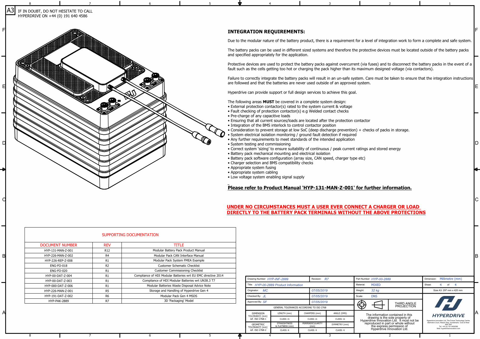
SUPPORTING DOCUMENTATION
DOCUMENT NUMBER REV TITLE
HYP-131-MAN-Z-001 R12
Modular Battery Pack Product Manual
HYP-226-MAN-Z-002 R4 Modular Pack CAN Interface Manual
HYP-226-REP-Z-008 R1
Modular Pack System FMEA Example
ENG-FO-018 R2 Customer Schematic Checklist
ENG-FO-020 R1
Customer Commissioning Checklist
HYP-00-DAT-Z-004 R1
Compliance of HDI Modular Batteries wrt EU EMC directive 2014
HYP-00-DAT-Z-003 R1
Compliance of HDI Modular Batteries wrt UN38.3 T7
HYP-000-DAT-Z-006 R1
Modular Batteries Waste Disposal Advice Note
HYP-226-MAN-Z-001 R5
Storage and Handling of Hyperdrive Gen 4
HYP-191-DAT-Z-002 R6 Modular Pack Gen 4 MSDS
HYP-PAK-2889 R7
3D 'Packaging' Model
INTEGRATION REQUIREMENTS:
Due to the modular nature of the battery product, there is a requirement for a level of integration work to form a complete and safe system.
The battery packs can be used in different sized systems and therefore the protective devices must be located outside of the battery packs
and specified appropriately for the application.
Protective devices are used to protect the battery packs against overcurrent (via fuses) and to disconnect the battery packs in the event of a
fault such as the cells getting too hot or charging the pack higher than its maximum designed voltage (via contactors).
Failure to correctly integrate the battery packs will result in an un-safe system. Care must be taken to ensure that the integration instructions
are followed and that the batteries are never used outside of an approved system.
Hyperdrive can provide support or full design services to achieve this goal.
The following areas MUST be covered in a complete system design:
• External protection contactor(s) rated to the system current & voltage
• Fault checking of protection contactor(s) e.g Welded contact checks
• Pre-charge of any capacitive loads
• Ensuring that all current sources/loads are located after the protection contactor
• Integration of the BMS interlock to control contactor position
• Consideration to prevent storage at low SoC (deep discharge prevention) + checks of packs in storage.
• System electrical isolation monitoring / ground fault detection if required
• Any further requirements to meet standards of the intended application
• System testing and commissioning
• Correct system ‘sizing’ to ensure suitability of continuous / peak current ratings and stored energy
• Battery pack mechanical mounting and electrical isolation
• Battery pack software configuration (array size, CAN speed, charger type etc)
• Charger selection and BMS compatibility checks
• Appropriate system fusing
• Appropriate system cabling
• Low voltage system enabling signal supply
Please refer to Product Manual 'HYP-131-MAN-Z-001' for further information.
UNDER NO CIRCUMSTANCES MUST A USER EVER CONNECT A CHARGER OR LOAD
DIRECTLY TO THE BATTERY PACK TERMINALS WITHOUT THE ABOVE PROTECTIONS
IF IN DOUBT, DO NOT HESITATE TO CALL
HYPERDRIVE ON +44 (0) 191 640 4586