dazhuang he an approach for isa-95 application to
TRANSCRIPT

DAZHUANG HE
AN APPROACH FOR ISA-95 APPLICATION TO
INDUSTRIAL SYSTEMS
Master’s Thesis
The subject was approved in the meeting of
the Department of Automation Council
MAY 2012
Examiners: Professor José Luis Martínez Lastra

I
ABSTRACT
TAMPERE UNIVERSITY OF TECHNOLOGY
Master of Science Programme in Machine Automation
He, Dazhuang: AN APPROACH FOR ISA-95 APPLICATION TO INDUSTRIAL
SYSTEMS Master of Science Thesis, 80 pages, 15 Appendix pages April 2012 Major subject: Factory Automation Examiner: Professor José Luis Martínez Lastra Keywords: ISA-95, GUI, B2MML, ERP, MES, UML
During last years software starts to play a significant role in the development of
industrial automation systems such as automated production systems. The growth of
computational resources of industrial controllers and computers, the communication and
information processing capabilities increase. As one of the benefits of this increase of
capabilities, it allows the implementation of functionally-rich protocols originally
developed by the IT world on the industrial devices and their supportive computer
systems. The simplification of network reconfiguration often relies on the ability to
dynamically plug or un-plug network nodes during the operation of the networked
system. Similar capability is desired in industrial automation, which extends it to a new
level – the ability to handle information not only on changing equipment and its state,
but on changing orders to be able to react to potentially new orders introduced to the
automated production system at run time.
A set of standards were proposed by the industrial and the research communities to
represent information on industrial automation systems. Among those, ISA-95-the
No.95 standard for the Instrumentation, Systems, and Automation Society-addresses
many aspects of the automation systems from manufacturing operations management
point of view. The standard includes models for equipment, material, personnel, process
segment, and others. Thus, to allow reconfigurability of industrial automation systems
the ISA-95 has been selected for the implementation of information models.
This thesis work provides a solution for the industrial application of ISA-95. The
thesis also defines an approach for the application of ISA-95 to industrial system, as
there is a lack of a generalized approach and supportive applications for the standard
implementation in industrial systems. A software tool (ISA-95 Tool) is implemented to
facilitate the application of the standard. The Industrial System Development Life Cycle
is revised to show the applicability of the standard for modelling industrial enterprise
entities. B2MML is used as XML-based format representation for ISA-95. The
developments are illustrated using two automated production lines.

II
Preface
This thesis work was carried out in Institute of Production Engineering at Tampere
University of Technology, as a meaningful summary of my Master of Science
Programme study of 2 years in Finland.
Here I would like to thank my parents for warming me up by their kind hearts till I
have courage and confidence to make my own decisions.
I also wish to extend my thanks to my supervisor Andrei Lobov and Professor Jose
L. Martinez Lastra for providing me strong and priceless support for the ideas and
designs.
Xiaoyun Deng, Bo Zhou and all the other FAST members, your hard working
encourages me a lot. Those hundreds of nights we spend together in the lab will always
push me to move forward.
Tampere, April, 2012
Dazhuang He
Orivedenkatu 8, C70 B
33720 Tampere
Finland

1
CONTENTS
Terms and Abbreviations .................................................................................... 6
1. Introduction ..................................................................................................... 8
1.1 Motivation and Problem Definition ......................................................... 8
1.2 Thesis Outline ...................................................................................... 10
2. The State of the Art ....................................................................................... 11
2.1 Mechanisms, Architectures and Standards.......................................... 11
2.1.1 Loose Coupling mechanism .................................................... 11
2.1.2 SOA ........................................................................................ 12
2.1.3 UML ........................................................................................ 13
2.1.4 OPC ........................................................................................ 15
2.2 ANSI/ISA standards ............................................................................. 17
2.2.1 ISA-95 ..................................................................................... 18
2.2.2 ISA-88 ..................................................................................... 22
2.3 Web service for information exchanging .............................................. 29
2.3.1 WSDL & BPEL ........................................................................ 29
2.3.2 WS4D ...................................................................................... 30
2.3.3 JMEDS .................................................................................... 30
2.3.4 Server ..................................................................................... 31
2.4 Problem statement ............................................................................... 31
3. Approaches and Models .............................................................................. 32
3.1 Refining of SDLC ................................................................................. 32
3.2 Business activities in the application—Use case study of ISA-95 Tool 35
3.3 Use case scenario study—Sequence Diagrams for ISA-95 Tool ......... 39
3.4 Extensions of relevant general models ................................................ 40
3.4.1 Personnel Model ..................................................................... 41
3.4.2 Equipment Model .................................................................... 42
3.4.3 Material Model ......................................................................... 42
3.4.4 Production Capability Model.................................................... 43
3.4.5 Process Segment Model ......................................................... 44
3.4.6 Process Segment Capability Model ........................................ 45
3.4.7 Production Schedule Model .................................................... 46
3.4.8 Production Performance Model ............................................... 47
3.4.9 Product Definition Information Model ...................................... 48
4. Industrial System Case Studies .................................................................... 50
4.1 Industry system development trends ................................................... 50
4.2 Study case—FESTO Line .................................................................... 51
4.3 Study case—FASTory ......................................................................... 59
5. Implementation ............................................................................................ 61
5.1 Object Models built for study cases ..................................................... 61
2
5.2 ISA-95 Tool .......................................................................................... 61
5.3 A specific version of ISA-95 for FASTory GUI ..................................... 67
5.4 B2MML ................................................................................................ 68
6. Conclusions & Future Work ......................................................................... 70
References........................................................................................................ 71
Appendix 1 : Assumed hierarchical computer control structure for a large
manufacturing complex CIM (computer integrated manufacturing) ................... 73
Appendix 2 : Assumed hierarchical computer control system structure for an
industrial plant (continuous process such as petrochemicals) .......................... 74
Appendix 3 : Assumed hierarchical computer control structure for an industrial
company (multi-plant) to show level 5 and its relationship to the revised level 4
.......................................................................................................................... 75
Appendix 4 : UML notation ................................................................................ 76
Appendix 5: Personnel model for FASTory Line ............................................... 77
Appendix 6: Equipment Model for FASTory Line .............................................. 78
Appendix 7: Material model for FASTory Line .................................................. 79
Appendix 8: Production capability model for FASTory Line .............................. 80
Appendix 9: Process Segment Model for FASTory Line ................................... 81
Appendix 10: Process segment capability for FASTory Line ............................ 82
Appendix 11: Production schedule model for FASTory Line ............................. 83
Appendix 12: Production Response Model for FASTory Line ........................... 84
Appendix 13: Product definition model for FASTory Line .................................. 85
Appendix 14: Equipment Object Model for FESTO Line ................................... 86
Appendix 15: Material Object Model for FESTO Line ....................................... 87
Appendix 16: Personnel Object Model for FESTO Line .................................... 88
Appendix 17: Process Segment Object Model for FESTO Line ........................ 89
Appendix 18 : An example of root elements in B2MML file ............................... 90
Appendix 19 : An example of generated .B2MML file format ............................ 91
Appendix 20 : An example of generated .B2MML file format in another
scenario ............................................................................................................ 92

3
Table of Figures
Figure 2.1an Example of Loose Coupling Mechanism ...................................... 11
Figure 2.2 an example of Strong Coupling Mechanism in comparison ............. 12
Figure 2.3 History of object-oriented methods and notation [17] ....................... 14
Figure 2.4 part of Equipment Object Model for FASTory Line .......................... 15
Figure 2.5 OPC Unified Architecture [25] .......................................................... 16
Figure 2.6 Conceptual Topology from an IT View [26] ...................................... 17
Figure 2.7 PERA Master Planning Work Flow [27] ........................................... 18
Figure 2.8 Functional enterprise-control model [28] .......................................... 19
Figure 2.9 Multi-level functional hierarchy of activities [28] ............................... 20
Figure 2.10 Generic activity model of manufacturing operations management
[28] .................................................................................................................... 21
Figure 2.11 Activity model of production operations management--an example
[28] extension model of activity model in manufacturing operation [28] ............ 21
Figure 2.12 a detailed version of Multi-Level Functional Hierarchy of Activities
[31] .................................................................................................................... 22
Figure 2.13 Standards in the batch control series [31] ..................................... 23
Figure 2.14 Process model (instance diagram) when not collapsed or expanded
.......................................................................................................................... 23
Figure 2.15 Typical process/procedure/equipment mapping to achieve process
functionality [31] ................................................................................................ 24
Figure 2.16 Physical Model in Part 1, SP88 [31] ............................................... 25
Figure 2.17 an example of recipe component encapsulation [31] .................... 26
Figure 2.18 Recipe types model [31] ................................................................ 27
Figure 2.19 Overview model of SP 88[31] ........................................................ 27
Figure 2.20 Pilot plant creation of equipment-independent recipe [33] ............. 28
Figure 2.21 Equipment-independent recipe from pilot plant development [33] . 29
Figure 2.22 WS4D in the structure of communication [34] ................................ 30
Figure 3.1 Traditional Information System Development Phases ..................... 32
Figure 3.2 the goal of ISA-95 Tool in system modification and information
exchange between ERP and MES .................................................................... 32
Figure 3.3 an architecture of the work flow refining SDLC ................................ 33
Figure 3. 4 detailed schedule in handbook on masters planning of PERA [27] . 35
Figure 3.5 Order Transferring Use Case Model for ISA-95 Tool ....................... 36
Figure 3.6 Interface Operation Use Case Model ............................................... 38
Figure 3.7 Sequence model for ISA-95 Tool ..................................................... 39
Figure 3.8 an example of extension of Personnel Class for Industrial System . 41
Figure 3.9 Personnel model .............................................................................. 42
Figure 3.10 Equipment Model ........................................................................... 42
Figure 3.11 Material model ............................................................................... 43
Figure 3.12 Production capability model ........................................................... 44
Figure 3.13 Process Segment Model ................................................................ 45
Figure 3.14 Process segment capability for FASTory Line ............................... 46

4
Figure 3.15 Production schedule model ............................................................ 47
Figure 3.16 Production Response Model .......................................................... 48
Figure 3.17 Product definition model ................................................................ 49
Figure 4.1 FESTO line (1) ................................................................................. 51
Figure 4.2 FESTO Line (2) ................................................................................ 52
Figure 4.3 Distributing and Testing Station (1) .................................................. 52
Figure 4.4 Distributing and Testing Station (2) .................................................. 53
Figure 4.5 Processing and Handling Station (1)............................................... 54
Figure 4.6 Processing and Handling Station (2) ............................................... 54
Figure 4.7 Robot Station .................................................................................. 55
Figure 4.8 ASRS Station (1).............................................................................. 56
Figure 4.9 ASRS Station (2).............................................................................. 56
Figure 4.10 Sorting Station ............................................................................... 57
Figure 4.11 Conveyor of FESTO line ................................................................ 57
Figure 4.12 FESTO Line PC No.1 ..................................................................... 58
Figure 4.13 FESTO Line PC No.2 ..................................................................... 58
Figure 4.14 FASTory-Line ................................................................................. 59
Figure 4.15 Mobile drawing ............................................................................... 59
Figure 4.16 Line Flow (2) .................................................................................. 60
Figure 4.17 Manufacturing Cell [39] .................................................................. 60

5
Table of Tables
Table 1 Fully developed description for order transferring use case model ............................... 37
Table 2 Intermediate description of ISA95Tool Operation Model ........................................... 38
Table 3 an example of person property attributes ....................................................................... 41
Table 4 Multi FMS Equipment Attributes ................................................................................... 65
Table 5 Multi FMS Material Attributes ...................................................................................... 66
Table 6 Multi FMS Equipment Capability Test Attributes ......................................................... 66
6
TERMS AND ABBREVIATIONS
ANSI American National Standards Institute
B2MML Business to Manufacturing Mark-up Language
BPEL Business Process Execution Language
CORBA Common Object Request Broker Architecture
DPWS Devices Profile for Web Services
ERD Entity Relationship Diagrams
ERP Enterprise Resource Planning
GAO U.S. Government Accountability Office
GUI Graphical User Interface
HMI Human machine Interface
ISA the Instrumentation System, and Automation Society
JMEDS Java Multi Edition DPWS Stack
MES Manufacturing Execution System
ODE Orchestration Direct Engine
OMT Object Modelling Technique
OOAD Object-Oriented Analysis & Design
OOSE Object-oriented Software Engineering
OPC OLE for Process Control
OASIS Organization for the Advancement of Structured Information
Standards
PFC Procedure Function Chart
SCADA Supervisory Control and Data Acquisition
SDLC System Development Life Cycle
SIIS Software Intensive Industrial System
SOA Service-Oriented Architecture
SOAP Simple Object Access Protocol

7
SSD System Sequence Diagram
SQL Structured Query Language
UML Unified Modelling Language
UDDI Universal Description, Discovery and Integration
UP Unified-Process
WS4D Web Service for Devices
WSDL Web Service Definition Language
XML Extensible Mark-up Language
XSD XML Schema Language

8
1. Introduction
1.1 Motivation and Problem Definition
The information flow in industrial system is getting larger both on its size and
complexity. The developing tendency of industrial systems shifts towards SIIS
(Software Intensive Industrial System) where software contributes essentially to the
design, construction, deployment and evolution in these systems. Being told the
difficulty of creating such systems is not news. GAO, known as U.S. Government
Accountability Office, attributes the poor success degree [1] of building software
intensive systems to the management [2], in detail, ERP and MES levels.
From modules to methodologies, from languages to services, several sets of ways
have been tried ,within 20 years, on connecting enterprise, control system and on
refining the SDLC (system development life cycle).
The examples are not limited to the following list: SOA (Service-Oriented
Architecture) – a paradigm developed for organizing and utilizing distributed
capabilities under different ownership domains [3]; OPC (OLE for Process Control) – a
common bridge for windows-based software applications and process control hardware;
loose coupling – a mechanism keeping different part in one system maintained their
own functionalities with communicating with each other through well-defined interfaces
[4],etc.
But the trials only focus on part of the solution, or cover much wider than the
specified field. For solving this problem, ISA-95 defines a complete functional model
for enterprise-control use as reflection of an organizational structure of functions which
can be replaced reaching different demands.
ISA-95 is originally a U.S. standard developed by the Instrumentation, Systems and
Automation Society, which has been adopted as an international one under IEC
(International Electro technical Commission)/ISO (International Organization for
Standardization) 62246. As currently envisioned, the ANSI (American National
Standards Institute) /ISA-95 series will consist of 5 parts, Enterprise-Control System
Integration.
Part1:Models and terminology
Part2:Object model attributes
Part3:Activity models of manufacturing operation management
Part4:Object models and attributes of manufacturing operations management
Part5:Business to Manufacturing transactions
The latest versions of Part 1, 2 and 3 are released on 2010 while part 4 and part 5 are
still under standardization. In this thesis work, a version released in 2000 of Part 1, a
version released in 2001 of Part 2 and a version released in 2005 of Part 3 are selected

9
to make a stable company with B2MML (Business to Manufacturing Mark-up
Language) (version 4010) for their compatibilities.
ISA-95 includes 3 main information areas of products, capabilities, and production
as a 5-level-structrued standard. Besides, the standard provides a reference model for
system organizing, allocating business to the different systems and information flow
between systems [5].
The tools to be introduced in this thesis work—“ISA-95 Tool” and “FASTory GUI
(Graphical User Interface)” serve as system boundary dealing with all the classes
beyond and under problem domain defined in ISA-95.00.02. In majority of the
industrial systems, the problem domain consists of 4 models [6]:
1) The personnel object model describes human resources defining different
classes of personnel.
2) The equipment object model is structured similarly--the object model supports
specifying requirements for different equipment classes.
3) The material model describes raw materials, intermediate products, and finished
products.
4) A process segment is one step/task/unit of work that must be performed to
complete a product.
The 5 other object models defined in ISA-95.00.02 beyond problem domain are
production capability model, process segment capability model, product definition
information model, production schedule model, production performance model. They
compose the upper level beyond problem domain.
For its high flexibility and continuity, ISA-95 is internationally used and has 30,000
members all over the world.
With a set of XML (Extensible Mark-up Language) meeting W3C (World Wide
Web Consortium)'s XML Schema language, as known as XSD, B2MML is treated as a
complete XML implementation of ISA-95. The .xsd templates implement the data
models in the ISA-95 standard. In the case of ISA95-Tool, .xml files are created as final
information carrier following B2MML templates [7].
From the perspective of an SDLC, the “support phases” [8] in ISA-95 are still weak.
This is reflected in the lack of tools and platforms based on the standard. This stage of
conceptualization greatly demands specific visualization to increase engineers’
efficiency on familiarizing and using this standard. The thesis work aims to improve the
manufacturing production efficiency by optimization of the information exchange
between ERP and MES level. This is aided by a tool developed in accordance with the
models in ISA-95, which also should contribute to the supporting phase of one
industrial system.
One of the case studies is a production line by FESTO located at FAST (Factory
Automation and System Technology) Lab, Tampere University of Technology. “ISA-95
Tool” is used to demonstrate the application of ISA-95 for the case study.
Another study case in this thesis work is FASTory Line that is an assembly line
used for research purposes in FAST Lab.

10
A modified version of “ISA-95 Tool”—“FASTory GUI” is also developed as an
alternative scenario built for target system. The detailed functionalities and related
researches are also presented.
1.2 Thesis Outline
As an introduction, the first chapter of the thesis work introduces the main content and
structure of the paper.
The second chapter contains a review of the previous work done in the very field
and cites related methodologies and theoretical model. Different from other works, this
thesis gives a comparatively comprehensive introduction of the methodologies in the
right beginning of the work, which increases the complexity of the content but keep the
integrity of the big structure.
This part starts from introducing one mechanism functioning in basic level, tracking
the reason of its being used in the architecture, in the standard and in the system. A
bottom-up state method is used for a better understanding of the inter connection.
Chapter 3 discusses in detail the approaches and models built before the
implementation work on this thesis work. 3 different types of UML (Unified Modelling
Language) models are used presenting the information structure building for FASTory
Line and FESTO Line; the toolkit functions as system boundary in sequence models and
use case models. Fully developed description and intermediate description table is
created as a manual to the models.
Chapter 4 is for the implementation and application of the thesis work, including the
building and the use of the tools—“ISA-95 Tool” and “FASTory GUI”. Different
phases in the software are presented by screenshots and the intermediate prototyping
flow is displayed. Besides, a necessary introduction to B2MML and its interfaces to
ISA-95 are also explained.
Chapter 5 analyses the structure and the information inside one created example
.xml file, known as the work result. The results from the 2 toolkits are compared and the
benefits and drawbacks are listed separately. Also part of the BPEL file is also listed as
part of the implementation work.
Chapter 6 is a conclusion to the whole topic and list possible after work in the future
research, followed by reference and appendices in the end.

11
2. The State of the Art
2.1 Mechanisms, Architectures and Standards
From loose coupling mechanism to standards such as OPC and ISA, engineers aim
on the common target to reduce the need for human work in the production of goods
and services, which is tried to be reached by different efforts on getting industrial
models dynamically involved.
2.1.1 Loose Coupling mechanism
From the perspective of structural analysis, the connections of industrial entities are
paid enough attention several decades ago. However, the efforts did not go further to its
goal—also the goal of every information evolution—the connection between
information systems. The tendency of connecting entities with well-defined interfaces
without breaking flexibilities, together with the development of information systems
itself makes ISA-95 a suited solution, or a so-called interface for this task.
Loose coupling means that different part of one system will maintain their own
functionalities and will communicate through a well-defined interface [4].
In the report of “Toward the definition of the Loose Coupling notion in a Composite
Service” by Anthony Hock-koon and Mourad Oussalah, loose coupling is defined in
more detail from prospective of semantic, syntactic and physical level.
Semantically, loose coupling means an abstract service and a composite loosely
coupled if this service participates in a non-essential capability of this composite and
these capabilities have a direct impact on the composite efficiency.
Syntactically, loose coupling stands for an abstract service loosely coupled with a
concrete service if there are optional solutions. The more there are suitable concrete
services, the weaker the coupling is.
Physically, a service can be seen loosely coupled if it is linked with more than one
other service (theoretically its composite service).
Figure 2.1An Example of Loose Coupling Mechanism
Device
CD Player DVD Player Voice Recoerder
Tester

12
Figure 2.2 an example of Strong Coupling Mechanism in comparison
The need for loose coupling mechanism comes from the requirement of business
processes and business applications flexibility. The processes and applications need to
make constant modifications to cater the new environment due to the changes in policy,
partnership and business focal point. In so-called on demand business, this mechanism
reacts to the changes in short time and reduces the cost for the modification.
As architecture with well-embedded loose coupling mechanism, SOA is worth
mentioning example with its high flexibility, reusability and stability.
2.1.2 SOA
There is always a need for intelligent SOA approaches in manufacturing operations
management. And one of the issues that the ISA-95 standard addresses is the interface
or exchange of data between the extended enterprise systems (sales, planning,
scheduling, and procurement).
The definition of SOA from OASIS (Organization for the Advancement of
Structured Information Standards) is:
“A paradigm for organizing and utilizing distributed capabilities that may be under
the control of different ownership domains. It provides a uniform means to offer,
discover, interact with and use capabilities to produce desired effects consistent with
measurable preconditions and expectations.” [3]
It is widely used in web service [9], pervasive computing [10] and business
applications in general.
Typically, those environments are envisioned to embody a number of devices with a
very rich set of functionalities. As many as possible resources are integrated in the
environment in an efficient way to provide the best support for user tasks and to
embody varying functions in a set of devices. The environments equip the ability to
extract these needs and build their replies according to their own capabilities. [11]
SOA in early times describes how services consumers and services providers can be
decoupled via discovery mechanisms in loosely coupled systems. Implementing a
service-oriented architecture means at the same time to deal with heterogeneity and
interoperability concerns. [12]
However, SOA in nowadays becomes the alternative model of object-oriented
model which has been existing for 20 years (object-oriented models are strongly
coupled). Although SOA does not exclude methodologies of object-oriented design (in
building single services), its whole design methodology still focus on services. In some
part of the SOA system, designers can be compatible with OOAD (Object-Oriented
Devices Tester
13
Analysis & Design without going against the core of its methodology. Chapter 2.1.3 in
this thesis is about the application of UML following OOAD’s track with the Unified
Process (as UP hereafter).
In recent years, SOA extends its development based on XML. It uses Web Services
Definition Language, as known as WSDL, to describe interface stepping to an adaptable
and robust mode beyond Interface Definition Language in CORBA (Common Object
Request Broker Architecture).
2.1.3 UML
UML, known as Unified Modelling language, is a specification defining a graphical
language for visualizing, specifying, constructing, and documenting the artefacts of
distributed object systems [13]. The object models in ISA-95 are depicted using the
Unified Modelling Language8 (UML) notational methodology.
The Object-oriented modelling language ushers a harvest season in the year between
1989 and 1994. During this time, the amount of Object-Oriented language creeps from
less than 20 to more than 50.
It takes long time for model users to compare and choose a proper language for their
models; moreover, the language designers propagate and consummate their product in
users’ practical use to win the market. That period of time, is called “Method War” in
history of computer science. The war comes to a dead-end until the middle of 90s a new
languages broke this dilemma. It is developed by 3 designers who quit from the
“battlefield”, Grady Booch, James Rumbaugh and Ivar Jacobson.
As one of the advocates leading in Object-Oriented method, Grady Booch expands
his work from Ada programming language to the wide domain of OO method. His work
“Booch 1993” copes well with design of the system.
Meanwhile, the team of James Rumbaugh team raises the concept of “Object
Modelling Technology”. The purposes of this modelling are
Testing physical entities before building them (simulation),
Communication with customers,
Visualization (alternative presentation of information), and
Reduction of complexity. [14]
The 2nd
version of OMT (Object Modelling Technique) copes well with analysis
and description to data-based system.
Ivar Jacobson raises use case method in Object-oriented Software Engineering (as
OOSE hereafter). Use-case method is a sharp weapon for describing system requirement
and this method is kept in UML later. OOSE copes well with business engineering and
requirement analysis.
The 3 designers each add properties from their original work to this new language,
making the name standing out of the corps—Unified Modelling Language.
The software industry accepted this new bier in a short time and considered it as the
standard modelling language for specifying software and system architectures. [15]

14
As a modelling notation, the influence of the OMT notation dominates (e. g., using
rectangles for classes and objects). Though the Booch "cloud" notation was dropped, the
Booch capability to specify lower-level design detail was embraced. The use case
notation from objectory and the component notation from Booch were integrated with
the rest of the notation, but the semantic integration was relatively weak in UML 1.1,
and was not really fixed until the UML 2.0 major revision.
Concepts from many other OO methods were also loosely integrated with UML
with the intent that UML would support all OO methods. Many others also contributed,
with their approaches flavouring the many models of the day, including: Tony
Wasserman and Peter Pircher with the "Object-Oriented Structured Design (OOSD)"
notation (not a method), Ray Buhr's "Systems Design with Ada", Archie Bowen's
timing analysis, Paul Ward's data analysis and David Harel's "Statecharts"; as the group
tried to ensure broad coverage in the real-time systems domain. As a result, UML is
useful in a variety of engineering problems, from single process, single user
applications to concurrent, distributed systems, making UML rich but also large [16].
Figure 2.3 History of object-oriented methods and notation [17]
Although UML is primarily intended for general-purpose modelling, it’s
expended to diverse specialized areas in UML Fig. 2.3. [17]
Beginning with UML 2.0, the UML Specification was split into two complementary
subsets: Infrastructure and Superstructure. The UML infrastructure specification defines
the foundational language constructs required for UML 2.0. It is complemented by
UML Superstructure, which defines the user level constructs required for UML 2.0. The
two complementary subsets constitute a complete specification for the UML 2
modelling language. [18] [19]

15
UML has matured significantly since UML 1.1. Several minor revisions (UML 1.3,
1.4, and 1.5) fixed shortcomings and bugs with the first version of UML, followed by
the UML 2.0 major revision that was adopted by the OMG in 2005. [20]
Although UML 2.1 was never released as a formal specification, versions 2.1.1 and
2.1.2 appeared in 2007, followed by UML 2.2 in February 2009. UML 2.3 was formally
released in May 2010. [21] UML 2.4 is in the beta stage as of March 2011.
In the book of “Object-oriented Analysis & Design with the Unified Process” by
John W.Satzinger, Robert B.Jackson and Stephen D.Burd, a model-driven approach to
analysis starts with use cases and scenarios and then defines problem domain classes
involved in the users’ work. Requirements discipline with use case diagrams, use case
descriptions, activity diagrams, and system sequence diagrams.
In this thesis work, the information mentioned above are expressed in a format of
B2MML—an XML implementation of ISA family standards.
One deficiency is, the UML version they use is 2.0, in this version UML does not
have XSD or XML files due to structural problems with the UML met model. [21]
The object models built with UML are also presented in Chapter 3 of this thesis
work. UML (Unified Modelling Language) models are used in the development of the
tools. The 9 object models, 86 objects and a whole set of attributes defined in ISA-
95.00.02 are extensions to the information models defined in ISA-95.00.01.
The structure and the frame allow users of addressing own information inheriting
the relationship between information blocks (known as classes in Object Models).
Figure 2.4 part of Equipment Object Model for FASTory Line
In an example of Equipment Object Model for FASTory Line, the information of
“State Buffer”, “Pen Feeder”, “Conveyor” is well classified and the generalization
between “Equipment Class” and them is also kept.
2.1.4 OPC
It has become a common goal of all industrial standards, to allow simple and accurate
through well-defined interfaces without stepping into programming interface and

16
communication models in low level. OPC is one of the standards who inherits this
characteristic and emphasises system’s interoperability.
OPC is short for “OLE for process control” in industrial automation and the
enterprise systems that support industry. Interoperability is assured through the creation
and maintenance of open standards specifications. [22]
It has emerged as the worldwide industrial standard based on DCOM
(Microsoft's Distributed Component Object Model) in recent years. The standard
provides the interoperability of Office products and information system on the company
level, including the core research domains of this thesis—ERP and MES. [23]
As a big part under development in OPC Foundation, OPC UA (Unified
Architecture) “provides the automation industry a tremendous opportunity to gain
efficiencies and create new solutions with the seamless interoperability of systems”
[24].
Considering that the automation industry must have a sense on how technologies
and innovations available today and tomorrow can provide a secure reliable
interoperable solution that addresses real needs, the OPC Foundation has been focusing
on collaborating with many of the other industry-standard organizations. The intention
of the OPC UA is that the various other industry-standard organizations information
models would be able to use this service to provide a complete solution for
deterministic interoperability.
OPC was designed to provide a common bridge for Windows based software
applications and process control hardware. Standards define consistent methods of
accessing field data from plant floor devices. This method remains the same regardless
of the type and source of data. An OPC Server for one hardware device provides the
same methods for an OPC Client to access its data as any and every other OPC Server
for that same and any other hardware device. The aim was to reduce the amount of
duplicated effort required from hardware manufacturers and their software partners, and
from the SCADA (Supervisory Control and Data Acquisition) and other HMI (Human
machine Interface) producers in order to interface the two. Once a hardware
manufacturer had developed their OPC Server for the new hardware device their work
Figure 2.5 OPC Unified Architecture [25]

17
was done to allow any 'top end' to access their device, and once the SCADA producer
had developed their OPC Client their work was done to allow access to any hardware,
existing or yet to be created, with an OPC compliant server.
Figure 2.6 Conceptual Topology from an IT View [26]
2.2 ANSI/ISA standards
This chapter aims to give general description of 2 ISA standards—ISA-95 and ISA-88.
In an industrial entity, a master plan is needed to provide overall guidance for the
development and implementation programs for the application of enterprise integration.
Such master plan provides the company the necessary preliminary planning and
operational guidance to be able to take full advantage of the above hardware and
software developments. In this thesis work, “Handbook on Master Planning and
Implementation for Enterprise Integration Programs” from Purdue Laboratory for
Applied Industrial Control is referenced covering all of the anticipated effort required to
integrate the whole of the involved operation. the work flow of the master plan is
depicted in Figure 2.7. The figure charts the information flow in the master plan when
suggested subject matters are used. The flow numbers in Figure 2.7 are also the chapter
number of the handbook. Eg. the content of “Chapter 1. Define Enterprise & Establish
Initial Program” in the handbook deals with the first part in the work flow of “Define
Enterprise Business Entity”.

18
Figure 2.7 PERA Master Planning Work Flow [27]
The ISA-95 standard is developed with the objective to reduce the cost, risk and
errors associated with implementing interfaces between enterprise and production
control systems. All these characteristics make it a good standard for the “standard” step
in a master plan.
2.2.1 ISA-95
ISA-95 defines a complete functional model for enterprise-control use (Figure
2.8Figure 2.8 Functional enterprise-control model). The model structure does not
reflect an organizational structure within a company, but an organizational structure of
functions. Different companies will place the functions in different organizational
groups.

19
Figure 2.8 Functional enterprise-control model [28]
Most of the information described in this functional model falls into three main
areas:
a) Information required producing a product
b) Information about the capability to produce a product
c) Information about actual production of the product
The Software Intensive Industrial System mentioned in Chapter 2, is set as example
of one production line in FAST Lab in Tampere University of Technology—FASTory
Line.
ISA-95 is the international standard being developed for integrating enterprise and
control systems. It provides a reference model for system organizing, allocating
business to the different systems and information flow between systems. ISA-95 is
originally a U.S. standard, but it has been adopted as an international standard under
IEC/ISO 62246. [5]
The purpose of the standard [27] is to:
a) Emphasize good integration practices of control systems with enterprise systems
during the entire life cycle of the systems;
b) Can be used to improve existing integration capabilities of manufacturing
control systems with enterprise systems
c) Can be applied regardless of the degree of automation
In accordance to other standards format in the same series (E.g., ISA 88, ISA
100.11a in ISA family), ISA-95 has 5 international parts:
ISA 95.00.01 Models and Terminology (Also IEC/ISO 62264-1)
ISA 95.00.02 Object Models and Attributes„ (Also IEC/ISO 62264-2)
ISA 95.00.03 Activity Models of Manufacturing (Operations Management)

20
ISA 95.00.04 Object Models and Attributes of Manufacturing Operations
Management
ISA 95.00.05 Business to Manufacturing Transactions
ISA-95 defines a functional hierarchy, illustrated in a Functional hierarchy model
Each level provides specialized functions and has characteristic response times, as
shown in Figure 2.9Figure 2.9 Multi-level functional hierarchy of activities [28].
a) Level 0 defines the actual physical processes.
b) Level 1 defines the activities involved in sensing and manipulating the physical
processes. Level 1 typically operates on time frames of seconds and faster.
c) Level 2 defines the activities of monitoring and controlling the physical
processes. Level 2 typically operates on time frames of hours, minutes, seconds,
and sub seconds.
d) Level 3 defines the activities of work flow to produce the desired end products. It
includes the activities of maintaining records and coordinating the processes. Level
3 typically operates on time frames of days, shifts, hours, minutes, and seconds.
e) Level 4 defines the business-related activities needed to manage a manufacturing
organization.
The standard presents the functions of an enterprise involved with manufacturing,
notational methodology which describes information flows between interfaces [29], the
categories of information [27] and the definition of the attributes [30] in object models.
As discussed in [8], “a model is a representation of some aspect of the system being
built. A variety of models should be built to encompass the detailed information that an
analyst collects and digests”. ISA standards make full use of activity models in
manufacturing operations management. Being cited in a generic activity model in
Figure 2.10Figure 2.10 Generic activity model of manufacturing operations
management [28], there extends 4 sub models (production operations, maintenance
operations, quality test operations and inventory operations) and the connection between
each module block is described specifically.
Figure 2.9 Multi-level functional hierarchy of activities [28]

21
As mentioned, the objectives of ISA-95 are to provide consistent terminology that
is a foundation for supplier and manufacturer communications. What is important to
SIIS is that ISA-95 provides consistent information models and operations models for
clarifying application functionality and how information is to be used.
Figure 2.11 Activity model of production operations management--an example [28]
extension model of activity model in manufacturing operation [28]
Figure 2.10 Generic activity model of manufacturing operations management [28]

22
2.2.2 ISA-88
As in Figure 2.12, Figure 2.12 a detailed version of Multi-Level Functional
Hierarchy of Activities of multi-level functional hierarchy of activities, “Batch Control”
contributes to the interface between Level 2 and Level 1. ISA-88 is the very standard
focusing on informative and normative information on Batch Control.
2.2.2.1 Batch control
Industrial manufacturing processes can be classified as either process manufacturing or
discrete parts manufacturing. Process manufacturing can be further classified as
continuous, batch or combination of the two.
Continuous process manufacturing automatically react to parameters’ change
without making modifications to the system while in discrete parts manufacturing any
changes must be made after cutting the production procedure.
Batch processes are discontinuous processes, which are neither discrete nor
continuous but have characteristics of both. Figure 2.13Figure 2.13 Standards in the
batch control series [31] is a structure of ISA 88 series’ functionality.
Figure 2.12 a detailed version of Multi-Level Functional Hierarchy of Activities [31]

23
Figure 2.13 Standards in the batch control series [31]
Part 5 of ISA 88 is not yet released as a formal documentation. A comprehensive
jointing system of SP88 and SP95 is presented in Technique Report 01.
2.2.2.2 Models in ISA 88
Take the process model as an example, any process can be generally divided into 4
process stages. ISA 88 defines the content of every stage [31, Clause 4.3.3 … Clause
4.3.5] and introduces the collapsing and expansion of the structure [36, Clause 4.3.6].
Figure 2.14 Process model (instance diagram) when not collapsed or expanded
24
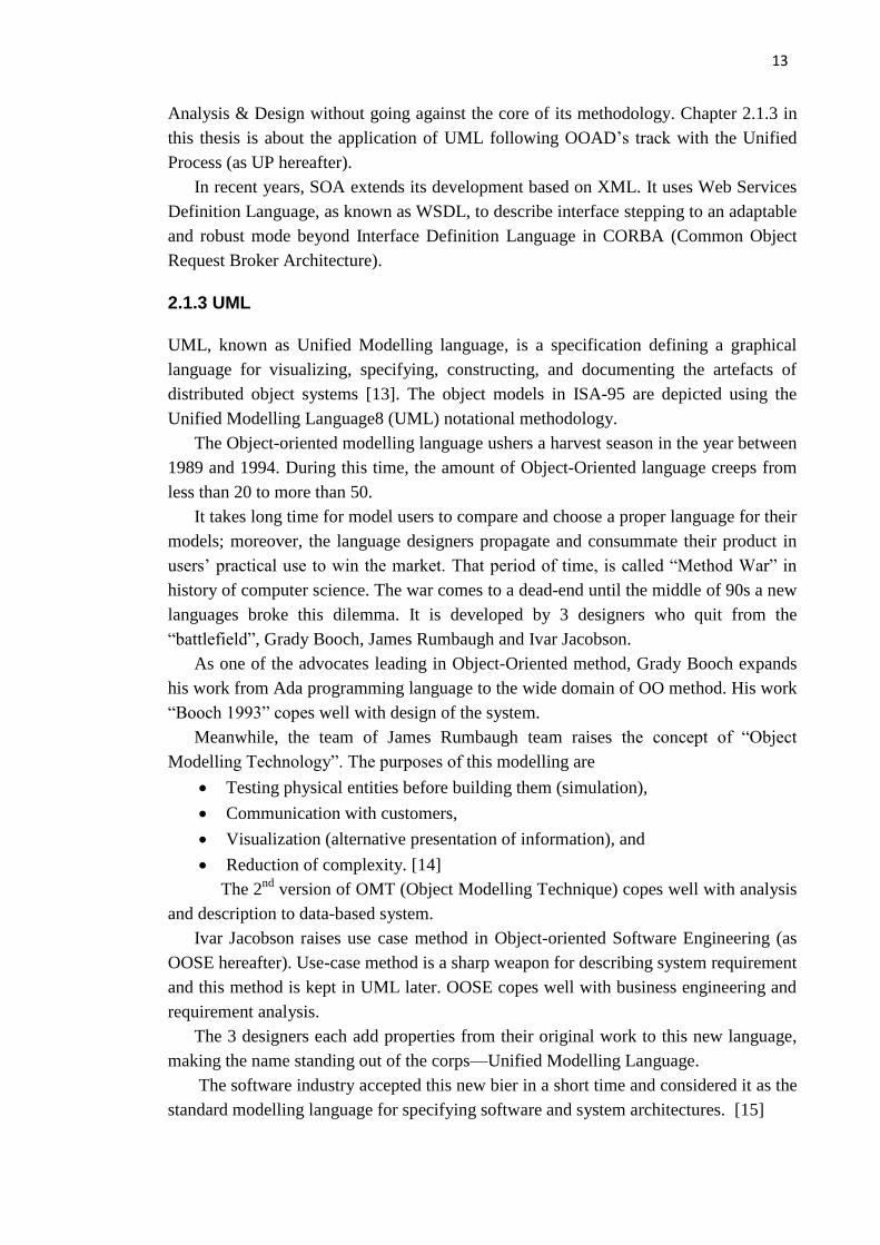
And the process stages in this model correspond to the other four stages in
Procedural Control Model individually. In Figure 2.15, it indicates that the
corresponding relationship of Process Model, Procedural Control Model and Physical
Model in factory floor shop.
Ref [31, Clause 5] divide structure for batch control into 3 categories: basic control,
procedure control & coordination control. Coordination Control has the function of
“directing, initiating and modifying” procedural control and [31, Clause 5.4.1] gives a
series of examples. One should be mentioned that procedure is a particular structure
only exists in batch control, its process-oriented characteristic further explain the
feasibility of being built upon process models.
Figure 2.15 Typical process/procedure/equipment mapping to achieve process
functionality [31]
A close look at Physical model again explains the different working field of SP88
and ISA95-62246—the enterprise, site, and area levels are more precisely defined in the
IEC/ISO 62264 and ANSI/ISA-95 standards (in dash lines in Figure 2.16) while SP88
focuses on the parts in lines. Also, this structure is kept in further descriptions to
equipment entities.

25
Figure 2.16 Physical Model in Part 1, SP88 [31]
2.2.2.3 Recipe
A recipe a collection of information that uniquely defines the manufacturing
requirements for a specific product, intermediate or equipment status change such as
clean-in-place, sterilize, etc.
The essence of recipe is a collection of components [31, Clause 6.4]; Figure 2.17
gives a landscape of the components.

26
Figure 2.17 an example of recipe component encapsulation [31]
There defines 4 recipes in this standard—general recipe, site recipe, master recipe
and control recipe, which are used in enterprise level, site area and equipment level,
separately. General recipe and site recipe can be transformed to master recipe and
control recipe and control recipe comes from the copy of master recipe. A recipe type
model is built for this relationship.
The concept of recipes allows for a high degree of processing flexibility that is
essential in many batch processes and allows for significant changes in process
activities to be defined by a recipe author without re-engineering equipment entities.

27
Figure 2.18 Recipe types model [31]
Besides, both general recipe and master recipe can be divided into 4 stages defined
in procedural control model. [31, Clause 6.6] focuses on the interfaces between control
recipes and equipment level by analysing the convergence of procedures.
Other 8 factors as process segmentation, exception handling, modes and states in
[31, Clause 7] are not considered in FASTory Line’s case.
2.2.2.4 Object Models in SP88
SP88 Part 2 uses a series of modelling languages in different clauses [32]. Ref [32,
Clause 4] defines data structure in a form of data models, the language is UML.
Figure 2.19 Overview model of SP 88[31]

28
In practical use, not every component is included in this overview model. E.g., [32,
Clause 4.3.4] uses a table of 10 attributes and a separate object model (building block
concept model for factory recipe system) to finish its description.
While [32, Clause 5] defines the structure of SQL (Structured Query Language)
relational tables for the exchange of selected batch control related information between
systems. Meeting with the requirements in Clause 4, the exchange of batch control
information are in 4 categories: Master and control recipe information, Process cell
equipment information, Schedule information and Production information.
The correlation of information exchange is visualized with ERD (Entity
Relationship Diagrams) language and recipe depiction methodologies in Clause 6 are in
PFC (Procedure Function Chart) language.
A large amount of tables and attributes enlarge the difficulty to apply ISA 88 in
production lines; ISA 88 provides a definition list to instantiate the deployment.
Another salvation for this is the large capability of the whole standard, an explanation to
this facet can be found in [32, Clause 5.1.2]—the exchange table structure allows the
transfer of either complete or incomplete subsets of a master recipe, equipment
description, etc.
The study case in this thesis—FASTory Line is still under test and adjustment for
research use, the capability makes it easier to integrate the incomplete information from
the production line into the SP88 models.
2.2.2.5 Equipment-Independent recipe
Instead of introducing general and site recipes separately, SP88 Part 3 uses the super
class of these 2 recipes—equipment-independent recipe [33]. An equipment-
independent recipe can be used either “as input to trial or pilot plant production” or “as
a result of trial or pilot plant production”. Figure 2.20 is an example of the application
in these two fields.
Figure 2.20 Pilot plant creation of equipment-independent recipe [33]

29
Figure 2.21 Equipment-independent recipe from pilot plant development [33]
Ref [33, Clause 6] also builds object model for equipment-independent recipe and
give short description to classes in this model.
2.3 Web service for information exchanging
As mentioned in the introduction, the information exchanged between the production
line and the low level controller will be packaged in .xml file. So the web service is also
designed for bridging MES and ERP levels in FASTory Line.
The significance of web service is self-contained and self-describing application
components. They communicate with open protocols. XML is the basis for every web
service.
The basic platform of web service is XML plus HTTP. XML provides a language
which can be used between different platforms and programming languages and still
express complex messages and functions.
The web service technologies involved in this thesis work are introduced in the
following part.
2.3.1 WSDL & BPEL
Following the description on WSDL in 2.1.2 in this thesis work, WSDL is an XML
format for describing network services as a set of endpoints operating on messages
containing either document-oriented or procedure-oriented information. The operations
and messages are described abstractly, and then bound to a concrete network protocol
and message format to define an endpoint. Related concrete endpoints are combined
into abstract endpoints (services). WSDL is extensible to allow description of endpoints
and their messages regardless of what message formats or network protocols are used to
communicate.

30
Together with SOAP (Simple Object Access Protocol) and UDDI (Universal
Description, Discovery and Integration), WSDL is one of the 3 platform elements of a
typical web service. Each move in the production line can be traced to an operation in a
.wsdl file.
BPEL (Business Process Execution Language), short for Web Services Business
Process Execution Language (WS-BPEL) is an OASIS (Advancing Open Standards for
the Information Society) standard executable language for specifying actions within
business processes with web services. Processes in BPEL export and import information
by using web service interfaces exclusively. Namely, BPEL orchestrates services that
are exposed using WSDL and define business processes that interact with external
entities through web services operations, which is also one of the design goals of BPEL.
One example on FASTory Line to explain this is, as for one of the robot cells, a .wsdl
file works well on triggering its operations as “selecting pens”, “calibrate” and “state
change feedback”. But to visualize more complicated tasks between all the elements in
each robot cell, the orchestration becomes necessarily in this step.
2.3.2 WS4D
WS4D is an abbreviation for Web Services for Devices and enables Web Services, the
foundation of Web 2.0, on networked embedded systems (devices). Cell phones,
wireless sensor nodes and a wild range of automation devices are some notable
examples. The application can be developed regardless of the heterogeneous devices
with different capabilities and communication standards. All the WS4D toolkits
released officially implement the DPWS (Devices Profile for Web Services) [34].
Figure 2.22 WS4D in the structure of communication [34]
2.3.3 JMEDS
JMEDS is the WS4D.org Java Multi Edition DPWS Stack [35]. It is a framework that
allows implementing and running DPWS Services, Devices and Clients. JMEDS
supports different Java Editions, including Java ME CLDC.

31
Part of the stack package is modified by laboratory members for better supporting
the devices before practice use. Here lists the features of the JMEDS framework:
Versatility of the platform supports all java editions: The JMEDS Local
Toolkit feature supports all Java platforms from CLDC up to SE and allows the
usage of platform specific features like disk and network access. With JMEDS it
is possible to choose the best platform for purpose.
Scalability :JMEDS is suitable for embedded devices with low amount of
memory and restricted computing power as well as for computing systems
without such limitations. The modularity of JMEDS allows the usage of
different modules to fit the needs of your project and ensures high adaptability.
Resource effective: With the module system it is possible to reduce the size of
JMEDS to save resources on your device. JMEDS uses only a minimal set of
external libraries to minimize the necessary dependencies. JMEDS is a
lightweight frame work.
Generic web interface: JMEDS comes along with a generic web interface
which allows fast access and usage of your services with your favorite web
browser.
Interpretation of WSDL at runtime: It is not necessary to create a WSDL
neither for your service nor for your device. The JMEDS generates the WSDL
on the fly within the request.
Compatibility: JMEDS is built for high compatibility, supports Microsoft
Windows 7 and is tested with the University of Rostock DPWS Stack.
2.3.4 Server
Tomcat and Resin are both open source servers with strong functionalities. The
extended versions have good support on business uses. While for medium and small
size industries as FASTory Line, basic version can cover most of the applications.
2.4 Problem statement
From mechanisms to standards, engineers make variety of trials on optimization of
automation systems in different levels and from different sights. Before ISA-95, there is
still lack of targeted standards connecting enterprises and control systems. Besides, the
supporting phase of system development life cycle of the standards is still weak. The
tools developed for this purpose set ground for systematic application of ISA-95
facilitated, which lead to the optimization of the information exchange between ERP
and MES level in an industrial system.
32
3. Approaches and Models
3.1 Refining of SDLC
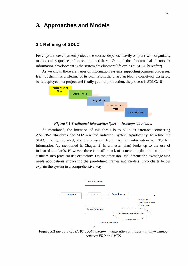
For a system development project, the success depends heavily on plans with organized,
methodical sequence of tasks and activities. One of the fundamental factors in
information development is the system development life cycle (as SDLC hereafter).
As we know, there are varies of information systems supporting business processes.
Each of them has a lifetime of its own. From the phase an idea is conceived, designed,
built, deployed in a project and finally put into production, the process is SDLC. [8]
Figure 3.1 Traditional Information System Development Phases
As mentioned, the intention of this thesis is to build an interface connecting
ANSI/ISA standards and SOA-oriented industrial system significantly, to refine the
SDLC. To go detailed, the transmission from “As is” information to “To be”
information (as mentioned in Chapter 2, in a master plan) looks up to the use of
industrial standards. However, there is a still a lack of concrete applications to put the
standard into practical use efficiently. On the other side, the information exchange also
needs applications supporting the pre-defined frames and models. Two charts below
explain the system in a comprehensive way.
Figure 3.2 the goal of ISA-95 Tool in system modification and information exchange
between ERP and MES

33
Figure 3.3 an architecture of the work flow refining SDLC
The initial goal of this thesis work is to create a solid application on analyzing
information as product orders referring to ISA-95 and other materials as PERA. To be
more detailed, in the very beginning of the industrial production, the production request
are usually delivered in a format of order, which contains information as production
requirements, manufacturing environment, etc. But due to the gap between enterprise
and control systems, as defined as the interface between ERP level and MES level in
ISA-95, the information exchange and other communication are not successfully
preceded. Thus a complete set of models specifying the exchanged information are
needed. In this thesis work ISA-95 is chosen as the reference standard of the object
models and other specifications working on “filling the gap”. Also, the standard is

34
proved (in PERA) to have the ability working as the reference making changes (e.g.
updating) enterprise entities. However, as mentioned before, the models and attributes
have large difficulties being accepted directly by industrial systems. Supportive
application refers to the standard is necessary for the convenience both on enterprise
and control systems` side. The software developed for this purpose in this thesis work,
ISA-95 Tool caters the need by transferring production order (software input) to
information understandable and digestible to control systems (software output).
B2MML is chosen as the .xml implementation language thus a set of B2MML files
carries the collected, specified information. The web services and operations in the
network can be further processed for the working structure and higher efficiency. The
process is called orchestration. However, the orchestration of the web services is not
considered necessary in this thesis. More work related to web services can be part of the
future work.
To identify the need for changes in enterprises and to carry out the changes
expediently and professionally, as mentioned in former section of the thesis, the purpose
of enterprise modelling is to provide such a discipline that organises all knowledge that
is needed in the whole industrial procedure. To provide the company the necessary
preliminary planning and operational guidance to be able to take full advantage of the
above hardware and software developments, it is necessary to develop applications for
industrial standards to fill the gap both for system modification and information
exchange purposes (see Figure 3.2).

35
Figure 3.4 detailed schedule in handbook on masters planning of PERA [27]
3.2 Business activities in the application—Use case study of
ISA-95 Tool
Use case diagrams serves as contents for the business events activities that must be
supported by the system. It is used to identify the use cases to identify how the system
will be used and which actors will be involved in which use cases. [8]
For this reason, use case diagrams and sequence models are depicted as part of the
implementation together with ISA-95

36
Figure 3.5 Order Transferring Use Case Model for ISA-95 Tool
ISA-95 is a toolkit, to go detailed, an interface for operations on industrial systems
and it is designed to work with Web Service framework in an auxiliary way. It can also
be used as a separated tool for placing orders to the line. The programming language for
the software is Java.
As depicted in Figure 3.5Figure 3.5 Order Transferring Use Case Model, the event flow
of the production starts from the customer setting production orders and ends with ISA-
95 Tool completes product segments according to GUI inputs. The core carrier for the
procedure is defined as “orders” in this project. For example, ISA-95 Tool engineers
receive orders from customers. An order is transferred between ISA-95 Tool Analyst,
system manager and ISA-95 Tool Operator and transformed into understandable and
readable languages. Control system integrated in industrial systems will digest and
execute the order to complete one process.
Creating use case diagrams is the only part of use case analysis. Careful system
development requires more detailed level of description.
37
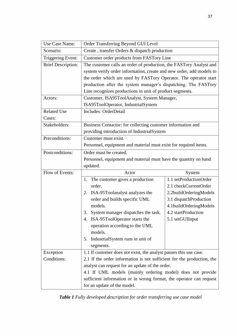
Table 1 Fully developed description for order transferring use case model
Use Case Name: Order Transferring Beyond GUI Level
Scenario: Create , transfer Orders & dispatch production
Triggering Event: Customer order products from FASTory Line
Brief Description: The customer calls an order of production, the FASTory Analyst and
system verify order information, create and new order, add models to
the order which are used by FASTory Operator. The operator start
production after the system manager’s dispatching. The FASTory
Line recognizes productions in unit of product segments.
Actors: Customer, ISA95ToolAnalyst, System Manager,
ISA95ToolOperator, IndustrialSystem
Related Use
Cases:
Includes: OrderDetail
Stakeholders: Business Contactor: for collecting customer information and
providing introduction of IndustrialSystem
Preconditions: Customer must exist.
Personnel, equipment and material must exist for required items.
Postconditions: Order must be created.
Personnel, equipment and material must have the quantity on hand
updated.
Flow of Events: Actor System
1. The customer gives a production
order.
2. ISA-95Toolanalyst analyzes the
order and builds specific UML
models.
3. System manager dispatches the task.
4. ISA-95ToolOperator starts the
operation according to the UML
models.
5. IndustrialSystem runs in unit of
segments.
1.1 setProductionOrder
2.1 checkCurrentOrder
2.2buildOrderingModels
3.1 dispatchProduction
4.1buildOrderingModels
4.2 startProduction
5.1 setGUIInput
Exception
Conditions:
1.1 If customer does not exist, the analyst pauses this use case.
2.1 If the order information is not sufficient for the production, the
analyst can request for an update of the order.
4.1 If UML models (mainly ordering model) does not provide
sufficient information or in wrong format, the operator can request
for an update of the model.
38
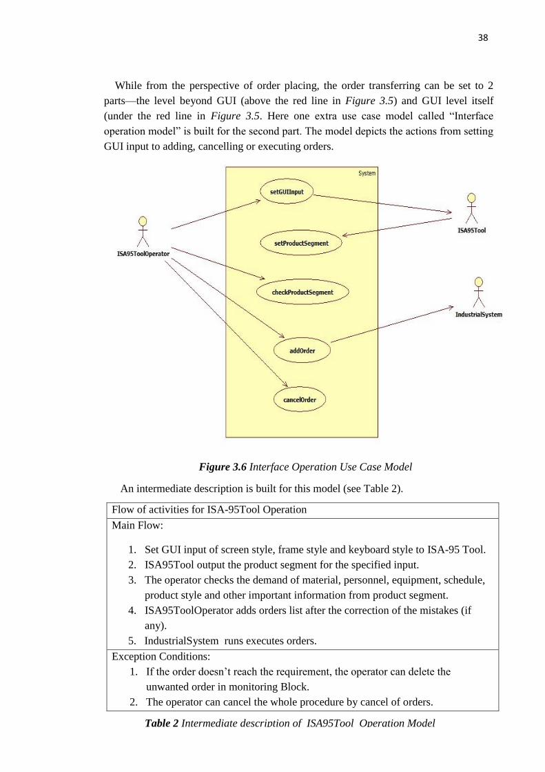
While from the perspective of order placing, the order transferring can be set to 2
parts—the level beyond GUI (above the red line in Figure 3.5) and GUI level itself
(under the red line in Figure 3.5. Here one extra use case model called “Interface
operation model” is built for the second part. The model depicts the actions from setting
GUI input to adding, cancelling or executing orders.
Figure 3.6 Interface Operation Use Case Model
An intermediate description is built for this model (see Table 2).
Flow of activities for ISA-95Tool Operation
Main Flow:
1. Set GUI input of screen style, frame style and keyboard style to ISA-95 Tool.
2. ISA95Tool output the product segment for the specified input.
3. The operator checks the demand of material, personnel, equipment, schedule,
product style and other important information from product segment.
4. ISA95ToolOperator adds orders list after the correction of the mistakes (if
any).
5. IndustrialSystem runs executes orders.
Exception Conditions:
1. If the order doesn’t reach the requirement, the operator can delete the
unwanted order in monitoring Block.
2. The operator can cancel the whole procedure by cancel of orders.
Table 2 Intermediate description of ISA95Tool Operation Model

39
3.3 Use case scenario study—Sequence Diagrams for ISA-95
Tool
A system sequence diagram (as SSD hereafter) is normally used in conjunction with the
use case descriptions to help document the details of a scenario within a use case. [8] In
most cases, sequence diagrams are used to explain object interactions and document
design decisions.
Figure 3.7 Sequence model for ISA-95 Tool
In this and the coming sequence diagrams, actors, actions and classes are defined in
accordance with ISA-95.00.02 and the dimension of the classes should be the same with
object models mentioned in Chapter 3 in this paper work.
The difference is, in the level beyond problem domain, IndsutrialSystem Engineer
starts an order from an order query system, which is not included in use case diagrams.

40
While the system boundary of the 2nd
sequence model, is set at the start point of the
problem domain. The work of getting orders as input and transforming it into “problem
domain” is completed in this level by ISA-95 Tool.
3.4 Extensions of relevant general models
Admittedly, the industry currently supports many methodologies that define formal
procedures specifying the process of gathering, analyzing applications’ requirements
and incorporating them into a program design. But still the complexity is very high. One
characteristic of UML—also the one enables the widespread industry support that the
language enjoys-is that it is methodology-independent.
The design of the following object models are based on basic knowledge of
industrial system manual books. As we know, several different projects may be required
in case of developing and updating the original system later. The building of models
must consider multiple levels of applications and face varying requirements from
consumers to maximize the benefit. While in this thesis, in fact also in most of the
researches, modeller focuses on the initial development project and not on the
supporting projects [8]. In other words, the primary concern of the thesis is to get an
industrial system operated and operated the very first time.
ISA-95 standard book also gives reference for expanding the classes. For example,
in 7.3.2.1 in ANSI/ISA-95.00.01, it defines personnel class as follow:
“A personnel class is a means to describe a grouping of persons with similar
characteristics for purposes of scheduling and planning. Any person may be a member
of zero or more personnel classes [36].”
Examples of the objects in a class in given:
Examples of personnel classes are “cook machine mechanics,” “slicing machine
operators,” “cat-cracker operator,” and “zipper line inspectors”.
As one of the possible scenarios in industrial systems, the extension of personnel
class is visualized by the generalization between “operator” class, “engineer” class and
“personnel class” (Figure 3.8). This structure shows the taxonomic relationship between
a more general element (the parent—personnel class) and a more specific element (the
child class—operator, engineer) that is fully consistent with the first element and that
adds additional information.
Also, the associations between 2 child classes and the qualification tests are built.

41
Figure 3.8 an example of extension of Personnel Class for Industrial System
Another issue worth being mentioned is that in most of the cases, attributes have
large flexibility. As indicated in Table 1, the title or even the data type can contain
different variation.
Table 3 an example of person property attributes
UML notation used in the models is attached as Appendix 4. The general models
and description on the models built for the 2 lines are as follow:
3.4.1 Personnel Model
The personnel model contains the information about specific personnel, classes of
personnel, and qualifications of personnel.

42
Figure 3.9 Personnel model
And with FASTory-Line’s high level of automation, the requirements for personnel
are comparatively low. Some of the attributes in this part can be left blank.
3.4.2 Equipment Model
The Equipment model contains the information about specific equipment, the classes of
equipment, equipment capability tests, and maintenance information associated with
equipment.
Figure 3.10 Equipment Model
3.4.3 Material Model
The material model defines the actual materials, material definitions, and information
about classes of material definitions. Material information includes the inventory of
raw, finished, and intermediate materials. The current material information is contained
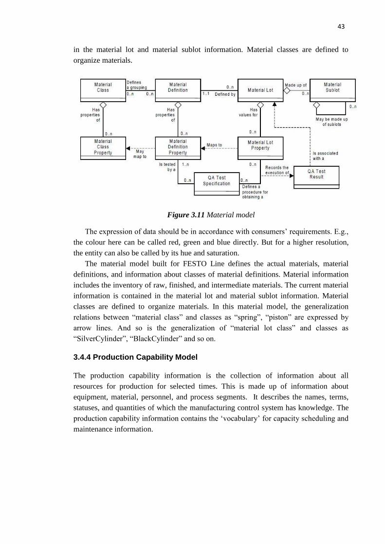
43
in the material lot and material sublot information. Material classes are defined to
organize materials.
Figure 3.11 Material model
The expression of data should be in accordance with consumers’ requirements. E.g.,
the colour here can be called red, green and blue directly. But for a higher resolution,
the entity can also be called by its hue and saturation.
The material model built for FESTO Line defines the actual materials, material
definitions, and information about classes of material definitions. Material information
includes the inventory of raw, finished, and intermediate materials. The current material
information is contained in the material lot and material sublot information. Material
classes are defined to organize materials. In this material model, the generalization
relations between “material class” and classes as “spring”, “piston” are expressed by
arrow lines. And so is the generalization of “material lot class” and classes as
“SilverCylinder”, “BlackCylinder” and so on.
3.4.4 Production Capability Model
The production capability information is the collection of information about all
resources for production for selected times. This is made up of information about
equipment, material, personnel, and process segments. It describes the names, terms,
statuses, and quantities of which the manufacturing control system has knowledge. The
production capability information contains the ‘vocabulary’ for capacity scheduling and
maintenance information.

44
Figure 3.12 Production capability model
In this model, where persons are members of multiple personnel classes then the
personnel capability information defined by personnel class should be used carefully
because of possible double counts, and personnel resources should be managed at the
instance level.
Obviously, the personnel capability attributes defined here, double counts with
personnel classes and there are no significant differences between them。So this object
should be deleted or ignored.
Moreover, take the personnel capability attributes as an example, when attributes as
“Capability Type”, “Location” and “Reason” are the same as that in Production
capability attributes, they should also not be counted in. ISA-95.00.02-2001 Annex A
shows simplified examples of multiple models in practical use.
3.4.5 Process Segment Model
A process segment is a logical grouping of personnel resources, equipment resources,
and material required to carry out a production step.

45
Figure 3.13 Process Segment Model
3.4.6 Process Segment Capability Model
A process segment capability is defined as a logical grouping of personnel resources,
equipment resources, and material that is committed, available, or unavailable for a
defined process segment for a specific time. It is related to one or more than one
products segment that can occur during production.

46
Figure 3.14 Process segment capability for FASTory Line
For presenting the change of the process segments between “AS-IS” and “TO-BE”,
2 separate process segment models are built for the production lines. The 2 process
segment models contains also majority of the information for both of the systems and
the transformation.
3.4.7 Production Schedule Model
Production information is defined in two model correspond to requests for production
and responses to the requests.

47
Figure 3.15 Production schedule model
There are multiple segments defined in the example. There is one master segment
of production that applies to the entire production request. The master segment is made
up of multiple nested segments for individually specified and reported segments of
production [37].
The rest parts attributes in the model, including personnel requirement and its
property, equipment requirement and its property, material produced requirement and its
property, material consumed requirement and its property, consumable expected and its
property are not necessary.
3.4.8 Production Performance Model
The performance of the requested manufacturing requests is the production
performance. Production performance is a collection of production responses.

48
Figure 3.16 Production Response Model
There are multiple segments defined in the example. There is one master segment of
production that applies to the entire production response. The master segment is made
up of multiple nested segments for individually reported segments of production [38].
3.4.9 Product Definition Information Model
The product definition information is information shared between production rules, bill
of material, and bill of resources.

49
Figure 3.17 Product definition model
FASTory Line is still in development state, some actual data can only be got after
it’s fully tested. As a result, the attributes of personnel actual attributes and personnel
actual property are to be announced.

50
4. Industrial System Case Studies
4.1 Industry system development trends
Software Intensive Industrial System can be seen all the software intensive system (as
SIS hereafter) for industrial use.
The first IEEE (Institute of Electrical and Electronics Engineers) definition of SIS
comes in July, 2007 in “IEEE Recommended Practice for Architectural Description of
Software-Intensive Systems”:
A software-intensive system is any system where software contributes essential
influence to the design, construction, deployment, and evolution of the system as a
whole.
We are in a world with diversity of devices, software, and high degree of
connectivity in complex systems. A new era has sent its invitation from every corner of
the world and in any known format. The humans are on their way catching these god-
speed steps. As mentioned in “A Science of Design for Software-Intensive Systems” by
Peter Freeman and David Hart, changing this situation will not happen overnight, but it
is also not possible to wait for another three decades.
Attendees at the 1968 NATO Software Engineering Conference in Garmisch,
Germany, built a foundation for the systematic creation of SIS [35]. Scientists have
realized how essential to create these systems based on a set of efforts and the process
have continued since then to develop a scientific basis for expanding this platform.
While for computer scientists, being told the difficulty of creating software-
intensive systems is not news. In the article of “Why software falls” [1], it mentions
that the success degree for SIS development is only 35%.
One of these problems is, individual who activates own intellectual capabilities can
take the complexity of some design tasks. Human intelligence is limited and additional
intellectual support is needed. So there are bases to agree that designers need
instrumental means which can give us a real time access to intellectual resources of the
corporate network. [36]
There are also different argues that a high percentage of failures in software
development are not due to bad capabilities of technicians but to deficiencies in used
methods. Like practically every article dealing with these problems in the popular press,
is cited “poor management” as the cause in referenced GAO report and lists more than
10 detailed reports to support the case. Specifics cited in this and the underlying reports
attribute failure to implement “a process for selecting, prioritizing, controlling, and
evaluating the progress and performance of all major information systems and
investments, (including specifically) disciplined, consistent procedures for software
requirements management, quality assurance, configuration management, and project
planning and tracking.” Among these, the deficiencies in configuration management

51
and quality assurance are not the root of the failure to meet the system objectives. Of
greater importance are persistent problems in requirements management and system
effectiveness assessment in all development phases [37].
Thereby, to enhance the productivity and quality of software intensive organizations
it is essential to introduce seamlessly efficient management and engineering practices
[38]. Since methods, models [36] and languages focus on partial optimization in a
system; here a larger concept is needed, a standard system to rule the innovation. The
solution chosen in this thesis work is ISA-95.
4.2 Study case—FESTO Line
FESTO line in FAST Lab can be seen as a modified version of Multi FMS line which
keeps all the functionalities (except for turning). It contains 10 equipment devices:
Milling FMS Station, conveyor, Distributing Station, Testing Station, Processing
Station, Handling Station, Robot Station, Assembly Station, Sorting Station and ASRS
(Automatic Storage and Retrieval System) Station. [40]
Figure 4.1 FESTO line (1)
Each station has its own controller, which means that each station can also be used
on its own. Synchronisation of the individual stations is performed via digital I/O at
level 1 (L1).

52
Figure 4.2 FESTO Line (2)
A second communication level (L2) for transferring data to the two computers at the
control level can be installed in addition to and independently of level 1. Profibus or
Ethernet is used here. Level 2 is not required for operation of the system; however it
does increase its ease of use.
The system is designed to process cylindrical parts. Different programs are
necessary for the CNC-machines. At the moment 5 programs for each CNC-machine
are integrated. It is also possible to create new programs for other parts. Another
difference is the material, aluminium and brass are available.
The system consist of two CNC- machines CONCEPT MILL105, CONCEPT
TURN105 a RV-3SB robot, a linear axis and the commissioning station.
There is no PLC-Controller; all control orders which are necessary for operation are
executed from the Drive unit of the robot.
Distributing process
Figure 4.3 Distributing and Testing Station (1)

53
Figure 4.4 Distributing and Testing Station (2)
For the distributing process, the station separates work pieces from the stack magazine
module.
The filling level of the stack magazine is monitored by means of a through-beam
sensor. A double-acting cylinder pushes out the work pieces individually. The Changer
module grips the separated out work piece using a suction cup. The arm of the transfer
unit, driven by a rotary drive, conveys the work piece to the transfer point of the
downstream station.
Testing process
For the testing process, the station determines the characteristics of the work pieces
received by the previous station, in this case the Distributing station.
The sensing module identifies the colour of a work piece and a capacitive sensor
detects each work piece regardless of their colour. A diffuse sensor identifies metallic
and red work pieces. Black work pieces are not detected by the diffuse sensor. A retro-
reflective sensor monitors whether the area above the work piece retainer is free before
the work piece is lifted by the lifting module. The analogue sensor of the measuring
module determines the height of the work piece. The output signal is digitalized via a
comparator with adjustable threshold value. A linear cylinder guides the correct work
pieces to the downstream station via the upper air cushioned slide. Other work pieces
are sorted on the lower slide.

54
Processing process
Figure 4.5 Processing and Handling Station (1)
Figure 4.6 Processing and Handling Station (2)
For the processing process, the station checks the characteristics of work pieces,
machines work pieces and supplies work pieces to a subsequent station.
Work pieces are tested and processed on a rotary indexing table. The rotary indexing
table is driven by a DC motor. The table is positions by a relay circuit, with the position
of the table being detected by an inductive sensor. On the rotary indexing table, the
work pieces are tested and drilled in two parallel processes. A solenoid actuator with an
inductive sensor checks that the work pieces are inserted in the correct position. During
drilling, the work piece is clamped by a solenoid actuator.
Finished work pieces are passed on via the electrical ejector.
Handling process
For the handling process, the handling station is equipped with a flexible two-axis
handling device.

55
Inserted work pieces are detected in the retaining device by an optical reflex light
sensor.
The handling device fetches the work pieces from the retaining device with the help
of a pneumatic gripper which is fitted with an optical sensor. The sensor differentiates
between ‘black’ and ‘non black’ work pieces. Workipieces can be deposited in different
slides on the basis of these criteria. Other sorting criteria can be defined if the station is
combined with other stations. It is possible to transfer work pieces to a subsequent
station.
Robot station
Figure 4.7 Robot Station
For the robot station, it assemblies work pieces or separates red/metallic and black work
pieces
Work pieces are transported by means of a slide on the retaining device.
The robot fetches the work piece from the retainer device with the help of a
pneumatic gripper. The work pieces are deposited on the assembly retainer. By means
of an optical sensor the orientation of the work piece is checked. An optical sensor is
fitted to the gripper jaw. This sensor differentiates between black and non-black work
pieces. The worpieces can be deposited into different magazines on the basis of these
criteria. It is also possible to transfer work pieces to a subsequent station. In
combination with the Assembly station the component parts of a short-stroke cylinder
are assembled into a functional cylinder.
Assembling process
For assembling process, the station supplies work pieces for the Robot station. The body
of the pneumatic cylinder for assembly is fed to the robot via a slide. The robot fetches
the body and places it to the identification position of the Assembly retainer module. An
optical sensor is fitted to the gripper jaw. This sensor differentiates between black and
non-black bodies. The robot establishes the orientation of the body and places it in the

56
correct orientation in the assembly position of the Assembly retainer module.
Depending on the colour of the body the robot takes a piston from the pallet an inserts it
into the body. For red and metallic bodies black pistons are used. For black bodies
metallic pistons are used. Afterwards the piston spring is inserted. The cap is picked up
at the Cap magazine module. The robot establishes the orientation of the cap and places
it in the correct orientation on the body. The finished pneumatic cylinder is placed on a
slide.
ASRS Process
Figure 4.8 ASRS Station (1)
Figure 4.9 ASRS Station (2)

57
For the ASRS Process, a shelf and a transporting beam is used for this station. The
classification of the storage and retrieval can be visualized by different programming.
Sorting Process
The Sorting station sorts work pieces onto three slides. Work pieces placed on the start
of the conveyor are detected by a diffuse sensor. Sensors upstream of the stopper detect
the work piece features (black, red, metal). Sorting gates actuated by short-stroke
cylinders via a deflector allow sorting of work pieces onto the appropriate slides. A
retro-reflective sensor monitors the level of the slides.
Figure 4.10 Sorting Station
Conveyor
Figure 4.11 Conveyor of FESTO line

58
For the Conveyor, it transfers half-processed components between stations. Several
pallet holders are used as the carrier of the components. 5 out of 8 stations’ portal are
connected to the conveyor.
PC1: For visualising and operating the MPS® system [41]
Figure 4.12 FESTO Line PC No.1
In practice, almost all large production systems are equipped with a system visualisation
feature. System visualisation and operation of the assembly line are provided on the
basis of WinCC or InTouch, depending on the PLC used in the system, as an optional
extra for FESTO Line.
PC2: Order input and visualisation of the CNC cell
Figure 4.13 FESTO Line PC No.2
The cell computer (PC2) of the CNC cell facilitates input of a number of different CNC
orders in one order batch. Each order can start its own CNC program via DNC. You can

59
also define whether an order should involve turning or milling or turning and milling. In
addition to order input, the CNC is dynamically visualised using a 3D representation.
4.3 Study case—FASTory
FASTORY-Line is a assembly line used for research purposes. In order to simulate the
production, drawings are done by robots. Its main advantage is that it can make
different drawings (to simulate parts of an assembly) and also different colours of ink
can be used to increase the complexity of the systems as well as production
customization.
Figure 4.14 FASTory-Line
The drawing consists of 3 parts: frame, screen and keyboard; there are 3 different
models for each part and 3 different pen colours (red, green and blue). The product has
729 variants. All the drawing robots are able to draw all the parts, it allows to make the
complete mobile phone or just one part to give some flexibility to the line. The material
to be used in the production will be paper and pens for the drawings.
Figure 4.15 Mobile drawing
The production line is composed by 11 robotic cells and one static buffer. Each
robotic cell is composed by an SCARA robot, a pen feeder, and 2 conveyors. 10 of the
cells are used for drawing and one for input/output of material.
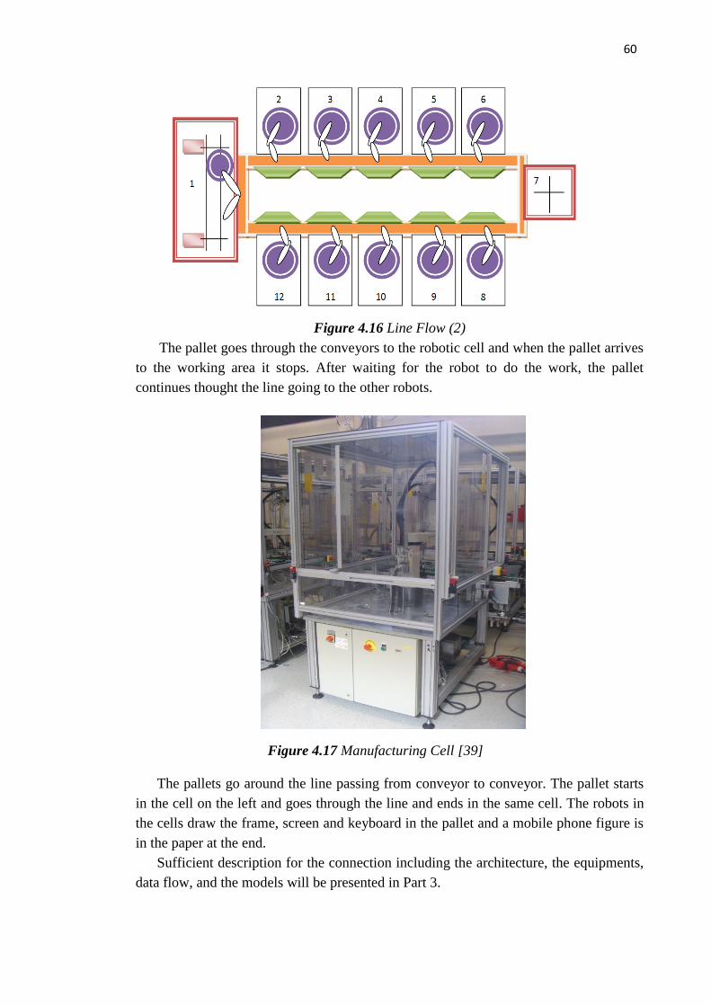
60
Figure 4.16 Line Flow (2)
The pallet goes through the conveyors to the robotic cell and when the pallet arrives
to the working area it stops. After waiting for the robot to do the work, the pallet
continues thought the line going to the other robots.
The pallets go around the line passing from conveyor to conveyor. The pallet starts
in the cell on the left and goes through the line and ends in the same cell. The robots in
the cells draw the frame, screen and keyboard in the pallet and a mobile phone figure is
in the paper at the end.
Sufficient description for the connection including the architecture, the equipments,
data flow, and the models will be presented in Part 3.
Figure 4.17 Manufacturing Cell [39]

61
5. Implementation
5.1 Object Models built for study cases
In Chapter 3, use case diagram and sequence diagram are made for the describing
ISA-95 Tool that is a basis for information models creation for SIIS following specific
B2MML (open) format in implementation phase. Also, the principles of generalized
model extension are explained. In this chapter, the object models for the study cases are
built (summarized in Appendix 5 to Appendix 17) as part of the implementation of the
work. The object models follow UML and ISA-88/95 to support basic operation of
FASTORY Line and FESTO Line production, which were introduced in Chapter 4.
In this chapter, the implementation of the approach outlined in Chapter 3 is
presented and validated with the case studies described in Chapter 4. Among 9 object
models and 86 objects defined in ISA-95, the modeller tries to provide as sufficient as
possible information on industrial systems to enlarge the compatibility of the system
and the standard. This is visualized by giving at least one example in most of the objects
and giving complete attributes in every object. Necessary explanation and process of
analysis are also added.
5.2 ISA-95 Tool
As mentioned in Chapter 2, there is a lack of visual-operating software as support
phase for ISA-95’s practical application. The knowledge still stays in the combination
of models and attributes, which extremely increases the difficulty of the application.
As one solution to the problem, “ISA-95 Tool” assigns ”order” as the core concept
and information carrier functioning in Manufacturing, Operation and Control level
(level 3 in ISA standard family) and Business Planning and Logistics level (level 4 in
ISA standard family) [33]. The process starts when the order is received from customers
and then transferred between system managers, analysts and operators. The process
ends up with creating and transferring an .xml file to low-level controller.
However, systems’ demand varies from factory to factory and so all models are
necessary keeping the process running in a practical industrial use.
The first phase presented as a frame allows users to select models by their demands
(Figure 5.).
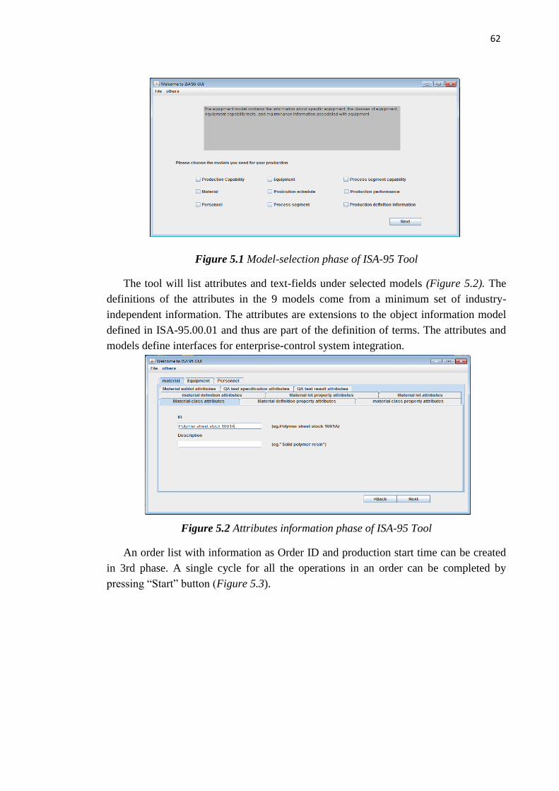
62
Figure 5.1 Model-selection phase of ISA-95 Tool
The tool will list attributes and text-fields under selected models (Figure 5.2). The
definitions of the attributes in the 9 models come from a minimum set of industry-
independent information. The attributes are extensions to the object information model
defined in ISA-95.00.01 and thus are part of the definition of terms. The attributes and
models define interfaces for enterprise-control system integration.
Figure 5.2 Attributes information phase of ISA-95 Tool
An order list with information as Order ID and production start time can be created
in 3rd phase. A single cycle for all the operations in an order can be completed by
pressing “Start” button (Figure 5.3).

63
Figure 5.3 Order-checking phase of ISA-95 Tool
Here lists the attributes from FESTO Line that need to be put into ISA 95 tools as
an example of the application of the tool.
EquipmentID EquipmentDescription EquipmentClass ClassProperties
StackMagazine The magazine barrel of the stack magazine holds up to 8 work pieces.
DistributingStation The Distributing station separates work pieces from the Stack magazine module.
SuctionCup A vacuum switch checks whether a work piece has been picked up.
DistributingStation
ChangerModule The Changer module is a pneumatic handling device. Work pieces are picked up using a suction cup and transferred
DistributingStation
OpticalSensorDS Senses the presence a part in the stack.
DistributingStation
RecognitionModule Material or colour identification is carried out by means of 2 proximity sensors with digital output.
TestingStation The testing station determines the characteristics of the work pieces received by the previous station, in this case the Distributing station.
LiftingModuleTS The work pieces are lifted from the sensing module to the measuring module by means of the lifting module.
TestingStation
MeasuringModule Consists of an analogue sensor for the height measurement of work pieces.
TestingStation
AirCushionedSlideModule
Used to transport work pieces. TestingStation
SlideModuleDS Used to transport work pieces. TestingStation
PicAlfaModule Uses industrial handling components.
HandlingStation The handling station is equipped SlideModuleHS The slide module is used to HandlingStation

64
transport and store work pieces.
with a flexible two-axis handling device.
ReceptacleModule The work pieces are inserted by the previous station into the Receptacle module.
HandlingStation
RotaryIndexingTableModule
The drive of the Rotary indexing table module is operated by a DC gear motor.
ProcessingStation The Processing station checks the characteristics of work pieces, machines work pieces and supplies
work pieces to a subsequent station.
TestingModule An inserted work piece is checked for correct positioning. If the hole points upwards, then the armature of the testing solenoid reaches its end position.
ProcessingStation
DrillingModule The drilling module is used to simulate the polishing of the hole of the work piece.
ProcessingStation
ClampingModule The clamping device clamps the work piece.
ProcessingStation
SortingGateModule It passes the work piece to a subsequent station.
ProcessingStation
CapacitiveProximitySensor
Not applicable ProcessingStation
SlideModuleRobot The slide module is used to transport and store work pieces. It is used as a worpiece feeder for the Retainer module.
RobotStation The Robot station assemblies work pieces or separates red/metallic and black work pieces.
RetainerModule The work pieces are inserted via a slide into the Retainer module. The work pieces are detected in the retainer by and optical reflex light sensor.
RobotStation
RobotModule Robot RV-2AJ with robot controller.- A vertical articulated arm robot is used to transport the work pieces.
RobotStation
Gripper A gripper is fitted to the robot arm. As actuator for the gripper a pneumatic parallel gripper is used.
RobotStation
AssemblyRetainerModule
Work pieces are assembled in the Assembly retainer module.
RobotStation
OpticalSensorRS Used to check the orientation of the work piece body and cap.
RobotStation
MagazineModule The magazine module is used for the storing of round work pieces.
RobotStation
SpringMagazineModu By means of the Spring AssemblyStation The
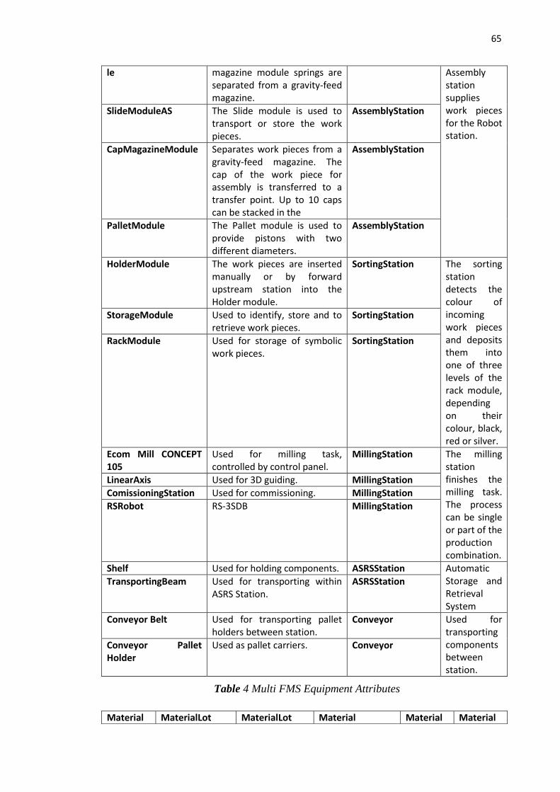
65
Table 4 Multi FMS Equipment Attributes
le magazine module springs are separated from a gravity-feed magazine.
Assembly station supplies work pieces for the Robot station.
SlideModuleAS The Slide module is used to transport or store the work pieces.
AssemblyStation
CapMagazineModule Separates work pieces from a gravity-feed magazine. The cap of the work piece for assembly is transferred to a transfer point. Up to 10 caps can be stacked in the
AssemblyStation
PalletModule The Pallet module is used to provide pistons with two different diameters.
AssemblyStation
HolderModule The work pieces are inserted manually or by forward upstream station into the Holder module.
SortingStation The sorting station detects the colour of incoming work pieces and deposits them into one of three levels of the rack module, depending on their colour, black, red or silver.
StorageModule Used to identify, store and to retrieve work pieces.
SortingStation
RackModule Used for storage of symbolic work pieces.
SortingStation
Ecom Mill CONCEPT 105
Used for milling task, controlled by control panel.
MillingStation The milling station finishes the milling task. The process can be single or part of the production combination.
LinearAxis Used for 3D guiding. MillingStation
ComissioningStation Used for commissioning. MillingStation
RSRobot RS-3SDB MillingStation
Shelf Used for holding components. ASRSStation Automatic Storage and Retrieval System
TransportingBeam Used for transporting within ASRS Station.
ASRSStation
Conveyor Belt Used for transporting pallet holders between station.
Conveyor Used for transporting components between station.
Conveyor Pallet Holder
Used as pallet carriers. Conveyor
Material MaterialLot MaterialLot Material Material Material

66
Table 5 Multi FMS Material Attributes
Table 6 Multi FMS Equipment Capability Test Attributes
LotID Description Properties PropertiesValue Class ClassDescription
RedCylinder
Big Cylinder in red
PropertiesRed Cylinder
In accordance with FESTO company standard
Cylinder As the main body of the assembled parts.
SilverCylinder
Big Cylinder in silver
PropertiesSilver Cylinder
In accordance with FESTO company standard
Cylinder
BlackCylinder
Small Cylinder in black
PropertiesBlack Cylinder
In accordance with FESTO company standard
Cylinder
CylinderCap
As the cover of the cylinder
Properties CylinderCap
In accordance with FESTO company standard
Cap As the cover of the cylinder.
Spring Placed inside the cylinder with a piston
Properties Spring
In accordance with FESTO company standard
Spring Placed inside the cylinder with a piston
BlackPiston
Placed in red/silver Cylinder
Properties BlackPiston
In accordance with FESTO company standard
Piston Placed in cylinders.
MetallicPiston
Placed in black Cylinder
Properties MetallicPiston
In accordance with FESTO company standard
Piston
EquipmentCapabilityTestID
EquipmentCapabilityTestDescription
MaintenanceRequest Maintenance WorkOrder
MSTest MillingStationTest Not applicable Not applicable
DSTest DistributionStationTest Not applicable Not applicable
TSTest TestingStationTest Not applicable Not applicable
HSTest HandlingStationtest Not applicable Not applicable
PSTest ProcessingStationTest Not applicable Not applicable
RSTest RobotStationTest Not applicable Not applicable
ASTest AssemblyStationTest Not applicable Not applicable
SSTest StoringStationTest Not applicable Not applicable
ConTest ConveyorTest Not applicable Not applicable

67
5.3 A specific version of ISA-95 for FASTory GUI
Like mentioned in Chapter 1 and Chapter 2, FASTory GUI is a tailored realization of
an approach for particular automated production system - FASTORY line described in
Chapter 4.. Starting from the action flow, the operator set input by choosing radio
button groups and making selection in combo boxes in GUI (Figure 5.4). The product
segment information in accordance with the choice will be displayed in the JTable
below simultaneously.
Figure 5.4 GUI operating interface (1)
After confirmation, the operator can check the demand of material, personnel, quipment,
schedule, product from product segment (see
Figure 5.5 GUI operating interface (2)Figure 5.5). The operator adds orders list after
the correction of the mistakes (if any).
Figure 5.5 GUI operating interface (2)
If the order doesn’t reach the requirement, the operator can delete the unwanted
order in monitoring Block (Figure 5.6). The operator can cancel the whole procedure by
cancel of orders.

68
Figure 5.6 GUI operating interface (3)
All the functions e.g., check production rule are defined according to the 9 object
models in Part 3: Approach and the entire object models refer to standards provided in
ISA-95.
When all the necessary information is collected correctly, the FASTory engineer
completes the order by pressing “Start” button on “order Monitoring” tab. After this, an
.xml file following B2MML’s format and collecting your choices will be created and
transferred to lower level.
5.4 B2MML
B2MML is an XML implementation of the ANSI/ISA-95 family of standards, known
internationally as IEC/ISO 62264. B2MML consists of a set of XML schemas written
using the XSD that implement the data models in the ISA-95 standard.
Companies interested in following ISA-95 for integration projects may use B2MML
to integrate business systems such as ERP and supply chain management systems with
manufacturing systems such as control systems and manufacturing execution systems.
B2MML is a complete implementation of ISA-95.
From v02, .xsd files are available as part of the package released by WBF.
In either FASTory GUI or ISA-95 Tool, an .xml file collecting inputs will be created
after the operations cycle and transferred to controllers in lower level.
The first step is done by adding values to an existing .xml file template. As
mentioned, from v02 of B2MML, .xsd files are available as part of the packages
released by WBF (The Organization for Production Technology). The template here is
created following .xsd file format. Little changes as adding root elements to .xsd files
are required if the format transformation is completed by an xml software. Part of the
B2MML code is attached (Appendix 18) as part of the work result.
Root elements need to be added to the source code of .xsd from B2MML. Set
Material.xsd file v4010 as an example, the code is available in Appendix 18. In SIIS as

69
FASTory Line and FESTO Line, not all data are in top level of importance, which
means only part of information can keep the system running processes.
Another reason to reduce the amount of the information is that garbage elements,
null elements and long header bring larger workload and difficulty for low controllers to
collect and analyze the information. For these reasons, another scenario is considered
that engineer chooses elements artificially and generate .xml file with chosen elements.
An example of this has been tested on FASTory GUI (see Appendix 19 & Appendix 20).
In the second scenario, the programming solution reduces the time needed analyzing
and extracting information for files.

70
6. Conclusions & Future Work
The ISA-95 standard models were analyzed and extended during this thesis. The
software tools were built to make use of the models that represent production systems
information.
ISA-95 is an important standard for the development connecting control system and
enterprises and B2MML was selected as implementation language for the standard.
“ISA-95 Tool” was developed as a GUI visualizing the models and attributes from
abstract concepts, putting them into practical industrial use. “FASTory GUI” is a
specialized version based on “ISA-95” taking FASTory Line as a study case. It provides
an example of how “ISA-95 Tool” can be extended to fit factories, enterprises in
different size and types as separate solutions, though it is already sufficient and
powerful enough working as an independent tool.
As mentioned in the beginning of Chapter 3, the initial goal of this thesis work is to
create a solid application on analyzing information as product orders referring to ISA-95
and other materials as PERA. The B2MML serve as the information carrier and the
implementation of the tool. However, the orchestration of the web services is not
considered necessary in this thesis. More work related to web services can be part of the
future work.
Another place for further developments and researches is that the model “production
performance” could be checked after at least one single process segment. Thus an .xml
file containing performance model information is needed backwardly from low-level
controller to “ISA-95 Tool”. Such function can be added but some changes on the web
service between the tool and the controller are needed.
Functions as importing and exporting project plan files could be added so that users
can “configure once, use every now and then”. Also, some factors out of pure
technology are considered here. Some make-up on interfaces helps on holding the
market when the tools are put into business use.

71
References
[1] Charente, R. N. (2005). Why Software Falls. IEEE Spectrum,vol. 42, #9, pp. 36-
43
[2] P. I. Sosnin, C. D., Conceptual Solution of the Tasks in Designing the Software
Intensive Systems
[3] http://xml.coverpages.org/soa.html.
[4] L. Kerschberg, The Role of Loose Coupling in Expert Database System
Architectures, 1989
[5] Ivan M.Delamer, J. L.Martinez Lastra, Factory Information Systems in
Electronics Production
[6] IMC-AESOP: ArchitecturE for Service-Oriented Process - Monitoring and
Control, D2.1
Reference Architecture and Models, 1st Release, Version: 24-May-2012 09:23,
unpublished
[7] ANSI/ISA-95.00.02-2001, Enterprise-Control System Integration Part2: Object
Model Attributes
[8] Martinez, P.; Amescua, A.; Garcia, J.; Cuadra, D.; Llorens, J.; Fuentes, J.M.;
Martin, D.; Cuevas, G.; Calvo-Manzano, J.A.; Feliu, T.S. On inferring
autonomous system relationships in the Internet
[9] 2009-12-02-pi-line-description-anni-lugo, not published
[10] http://www.festo-didactic.com/int-en/learning-systems/mps-the-modular-
roduction-system/mps-
transfersystem/?fbid=aW50LmVuLjU1Ny4xNy4yMC4xMTIz
[11] Manual book of Multi FMS Line
[12] John W.Satzinger, Rober B.Jackson, Stephen D.Burd,Object-oriented Analysis
& Design with the Unified Process
[13] G. Alonso, F. Casati, H. Kuno, and V. Machiraju. Web Services. 2003. isbn 978-
3-540-44008-6.
[14] M. Weiser. The computer for the 21st century, Scientific Anerican, pages 94-
104,1991.
[15] Toward the definition of the Loose Coupling notion in a Composite Service,
Anthony Hock-koon, Mourad Oussalah.
[16] Cardoso, Jorge; Sheth, Amit P. (2006). "Foreword". Semantic Web Services,
Processes and Applications. SEMANTIC WEB AND BEYOND: Computing for
Human Experience. Foreword by Frank Leymann. Springer. xxi. ISBN 978-0-
387-30239-3.
[17] Catalog of OMG Modeling and Metadata Specifications,
http://www.omg.org/technology/documents/modeling_spec_catalog.htm.
[18] Terje Totland (1997). 5.2.7 Object Modeling Technique (OMT) Thesis,
Norwegian University of Science and Technology (NTNU), Trondheim.
[19] Architecting systems with UML 2.0, Morgan Björkander and Cris Kobryn.
[20] ISO/IEC 19501:2005 Information technology – Open Distributed Processing –
Unified Modeling Language (UML) Version 1.4.2.
[21] http://en.wikipedia.org/wiki/Unified_Modeling_Language
[22] Unified Modeling Language: Superstructure,version 2.0, formal/05-07-04.
[23] Unified Modeling Language: Infrastructure, version 2.0, formal/05-07-05.
[24] http://www.omg.org/spec/UML/2.0/.
[25] http://www.omg.org/spec/UML/.
[26] http://www.opcfoundation.org/.

72
[27] Theodore J. Williams, Gary A. Rathwell, Hong Li, A HANDBOOK ON
MASTER PLANNING AND IMPLEMENTATION FOR ENTERPRISE
INTEGRATION PROGRAMS, February 2001
[28] A Study on OPC Specifications: Perspective and Challenges, Mai Son, Myeong-
Jae Yi.
[29] OPC Unified Architecture infrastructure for the future--A common, open,
platform-independent, web services facility that standardizes automation
transactions.Thomas Burke.
[30] http://www.opcfoundation.org/01_about/April19_OPC-
DISPLAY%20LAYOUT.pdf
[31] Manufacturing Operation Management, Peter Owen,Eli lilly & Co, Dennis
Brandl, BR&L Consulting, University of Cambrige, Institute for Manufacturing.
[32] ANSI/ISA-95.00.01–2000 Enterprise-Control System Integration, Part 1:
Models and Terminology.
[33] ANSI/ISA-95.00.03-2005,Enterprise-Control System Integration Part 3: Activity
Models of Manufacturing Operations management.
[34] Structured Analysis and System Specification by DeMarco, 1978, Prentice Hall,
Inc., Upper Saddle River, NJ.
[35] ANSI/ISA-95.00.02-2001, Enterprise-Control System Integration Part2: Object
Model Attributes.
[36] ANSI/ISA-88.00.01-2010, Batch Control Part 1: Models and Terminology.
[37] ANSI/ISA-88.00.02-2001, Batch Control Part 2: Data Structures and Guidelines
for Languages
[38] ANSI/ISA-88.00.03-2001, Batch Control Part 3: General and Site Recipe
Models and Representation
[39] http://ws4d.e-technik.uni-rostock.de/
[40] Naur, P. and Randell, B., Eds. Software Engineering. Report of a conference
sponsored by the NATO Science Committee,Garmisch,Germany, Oct. 7–11,
1968.
[41] Conceptual Solution of the Tasks in Designing the Software Intensive Systems
P. I. Sosnin, Computer Department, Ulianovsk State Technical University,
Ulianovsk, , Member, IEEE.
[42] Systems Engineering for Software-Intensive Projects Herbert Hecht SoHaR
Incorporated Beverly Hills, California

73
Appendix 1 : Assumed hierarchical computer control structure for a
large manufacturing complex CIM (computer integrated
manufacturing)

74
Appendix 2 : Assumed hierarchical computer control system
structure for an industrial plant (continuous process such as
petrochemicals)

75
Appendix 3 : Assumed hierarchical computer control structure for an
industrial company (multi-plant) to show level 5 and its relationship
to the revised level 4
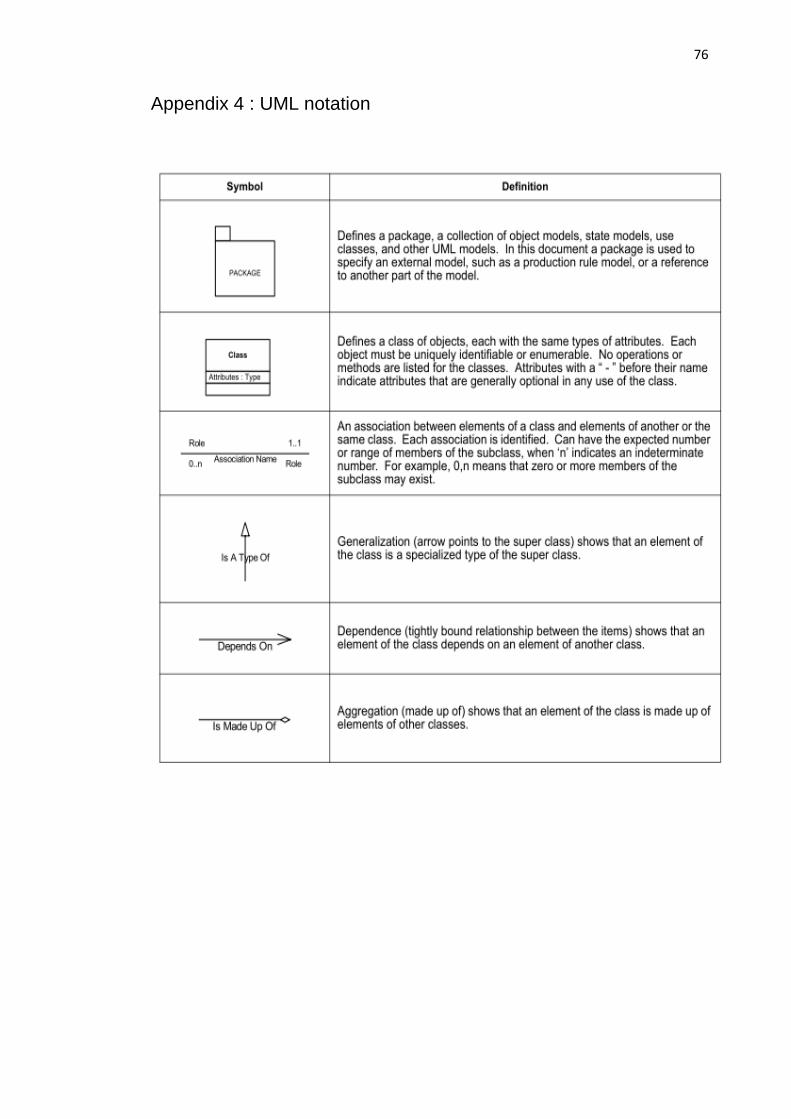
76
Appendix 4 : UML notation

77
Appendix 5: Personnel model for FASTory Line

78
Appendix 6: Equipment Model for FASTory Line

79
Appendix 7: Material model for FASTory Line
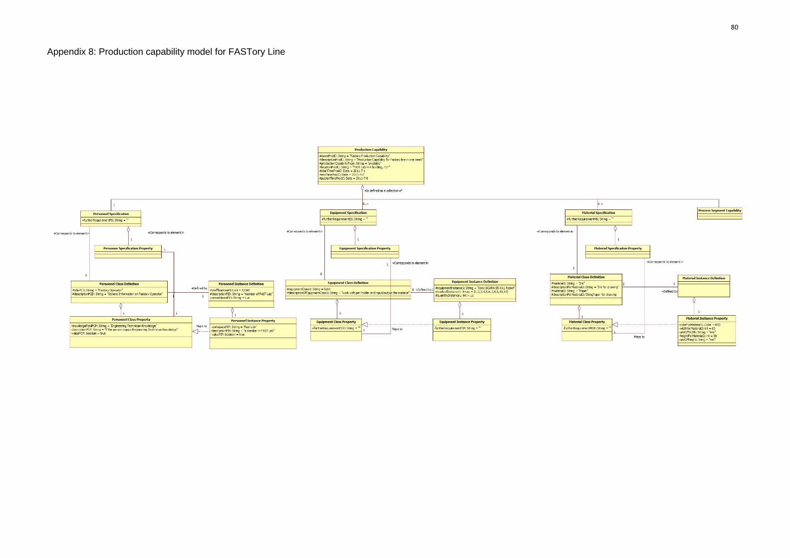
80
Appendix 8: Production capability model for FASTory Line

81
Appendix 9: Process Segment Model for FASTory Line

82
Appendix 10: Process segment capability for FASTory Line

83
Appendix 11: Production schedule model for FASTory Line

84
Appendix 12: Production Response Model for FASTory Line
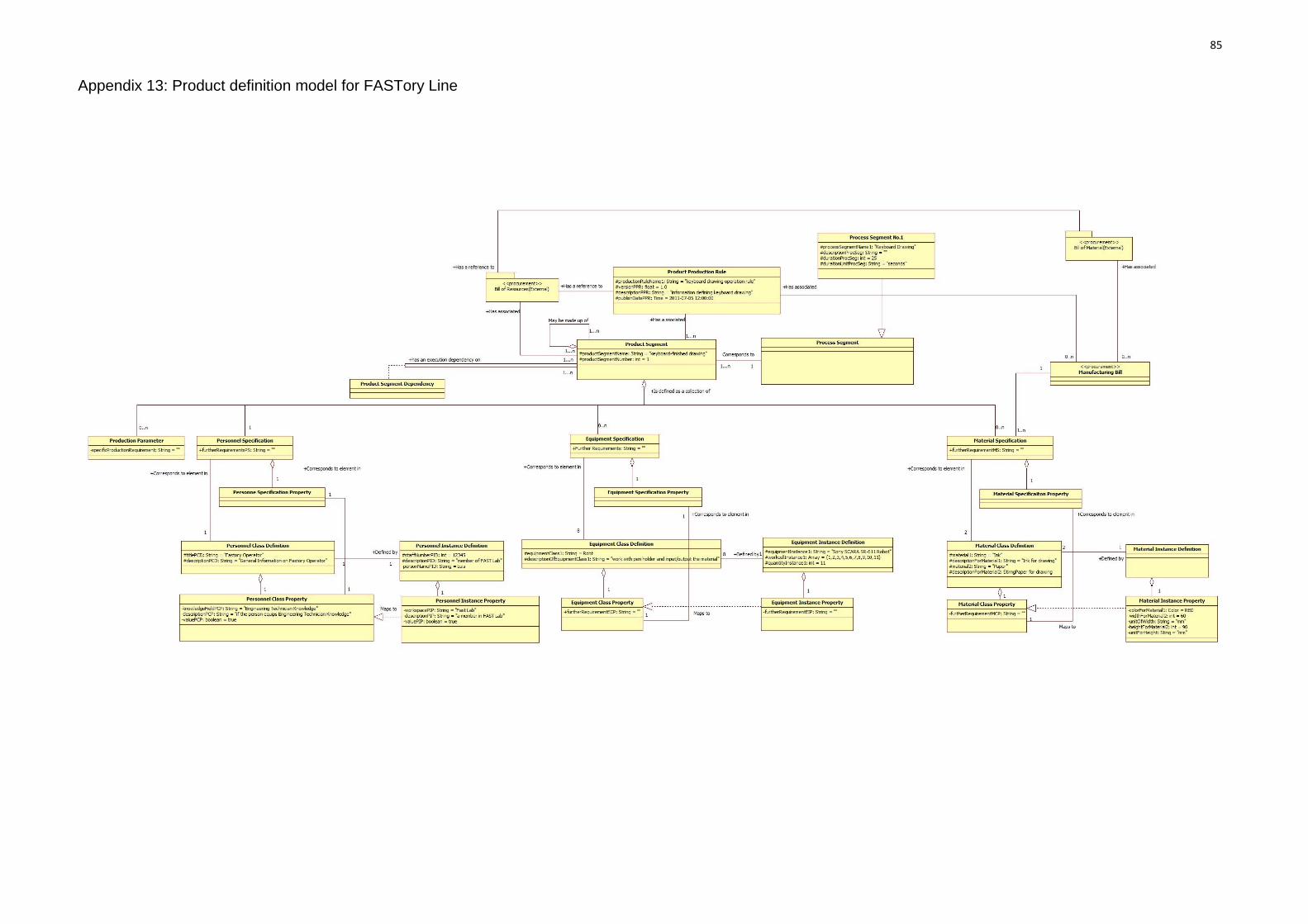
85
Appendix 13: Product definition model for FASTory Line

86
Appendix 14: Equipment Object Model for FESTO Line

87
Appendix 15: Material Object Model for FESTO Line

88
Appendix 16: Personnel Object Model for FESTO Line

89
Appendix 17: Process Segment Object Model for FESTO Line

90
Appendix 18 : An example of root elements in B2MML file
<xsd:element name="root_element">
<xsd:complexType>
<xsd:sequence>
<xsd:element ref="MaterialInformation" type="MaterialInformationType"/>
<xsd:element ref="MaterialClass" type="MaterialClassType"/>
<xsd:element ref="MaterialDefinition" type="MaterialDefinitionType"/>
<xsd:element ref="MaterialLot" type="MaterialLotType"/>
<xsd:element ref="QAMaterialTestSpecification"
type="QAMaterialTestSpecificationType"/>
<xsd:element ref="MaterialSubLot"
type="MaterialSubLotType"/>
<xsd:element ref="GetMaterialInformation"
type="GetMaterialInformationType"/>
<xsd:element ref="ShowMaterialInformation"
type="ShowMaterialInformationType"/>
</xsd:sequence>
</xsd:complexType>

91
Appendix 19 : An example of generated .B2MML file format
<?xml version='1.0' encoding='UTF-8'?>
<root_element xsi:schemaLocation="http://www.wbf.org/xml/B2MML-V0401
C:\Users\he\Desktop\B2MML-BatchML-V0401-Schema\B2MML-V0401-
Material.xsd"xmlns="http://www.wbf.org/xml/B2MML-V0401"
xmlns:xsi="http://www.w3.org/2001/XMLSchema-instance">
<MaterialInformation xmlns="http://www.wbf.org/xml/B2MML-V0401"/>
<MaterialClass xmlns="http://www.wbf.org/xml/B2MML-V0401">
<ID xmlns="http://www.wbf.org/xml/B2MML-V0401">VALUE</ID>
</MaterialClass>
<MaterialDefinition xmlns="http://www.wbf.org/xml/B2MML-V0401">
<ID xmlns="http://www.wbf.org/xml/B2MML-V0401">VALUE</ID>
</MaterialDefinition>
<MaterialLot xmlns="http://www.wbf.org/xml/B2MML-V0401">
<ID xmlns="http://www.wbf.org/xml/B2MML-V0401">VALUE</ID>
</MaterialLot>
…………
</root_element>

92
Appendix 20 : An example of generated .B2MML file format in another
scenario
<?xml version="1.0" encoding="UTF-8"?>
<?xml-stylesheet type="xsl" href="FASToryOrder.xsl"?>
<Orders>
<!--An Order Catalog-->
<Order ID="02">
<amount>99</amount>
<time>Tue Sep 20 12:58:58 EEST 2011</time>
<Formats>
<frameFormat Color="1">1</frameFormat>
<screenFormat Color="0">0</screenFormat>
<keyboardFormat Color="1">1</keyboardFormat>
</Formats>
<Materials>
<Material sn="01">
<ID>RedInk</ID>
<Amount>90</Amount>
<Unit>ml</Unit>
</Material>
<Material sn="02">
<ID>GreenInk</ID>
<Amount>0</Amount>
<Unit>ml</Unit>
</Material>
<Material sn="03">
<ID>BlueInk</ID>
<Amount>0</Amount>
<Unit>ml</Unit>
</Material>
<Material sn="04">
<ID>Paper</ID>
<Dimension>60 x 90</Dimension>
<Unit>mm x mm</Unit>
</Material>
</Materials>
</Order>
<Order>
<amount>000</amount>
<time>0000</time>
</Order>
</Orders>