decentral emergency- / safety-lighting system type cls 24/sv
TRANSCRIPT

Decentral emergency- /
safety-lighting system
Type CLS 24/SV
����������������� ���
����������� ����
2
INOTEC Sicherheitstechnik GmbH is a medi-um-sized business creating innovative and customer-oriented developments in the field of emergency and safety lighting.
A dynamic team with flexible and competent staff provides reliable advice on all matters concerning products, planning and regulations.
Modern, technically sophisticated products set new standards worldwide, such as emergency lighting systems with JOKER technology or the D.E.R. dynamic escape routing guidance system.
This catalogue contains the INOTEC emergency system CLS and complementary products. Should you require further information, please do not hesitate to contact our regional techni-cal sales staff directly.
CLS 24/SVNew standards allow new ideas!
Contents
Page
Safety target functional integrity 3
Function, design and features 4 / 5
Central monitoring 6 / 7
Technical data CLS 24 / SV 8 / 9
System components and options 10 / 11
Copyright: INOTEC Sicherheitstechnik GmbH, EnseReproduction and duplication, even of extracts,by approval of manufacturer only.
Subject to technical changes.
The emergency systems in this catalogue are not compatible to monitoring systems of type INOTEC SVPC, SV-central or multifunctional controller.

3
CLS 24/SVSafety target functional integrity
The CLS 24 system is an ideal combination, in relation to the emergency level and safety target, of the advantages of decentralized self-contained luminaires with the high handling comfort of a central battery system.
The CLS 24 system guarantees the secure supply of all emergency- and escape route luminaires during normal/battery operation as well as the automatic testing of the device and every single luminaire (up to 20 per final circuit). Even the proved “Joker-Technology-Function”, to realise a combination of non-maintained and switch-maintained luminaires in one final circuit, is included in the CLS 24.
With the CLS 24 system, INOTEC, as an inno-vative emergency lighting manufacturer, is setting a new trend which reflects changes in the market for light fixtures and current regula-tions.
An adaption of the system technology is need-ed, due to the application of LED in the section emergency lighting. LEDs provide advantages concering durability, temperature range and use of energy.
The self-sufficient CLS 24 system is designed to supply only luminaires within a fire zone. No cost-intensive circuitry is therefore re-quired and an extremely high level of safety is achieved.
���������� ����������
����������
��������������������
���������� ����������
Fire zone max 1600m²
��������������������
���������� ����������
���
Fire zone max 1600m² Fire zone max 1600m²Fire zone max 1600m²
E30
CLS
CLS
CLS
CLS
sub-DB EL
sub-DB EL
sub-DB EL
sub-DB EL
sub-DB EL
Main DB EL
CLS
CLS
E30
���������� ����������
����������
��������������������
���������� ����������
��������������������
���������� ����������
��� ������
In the event of main DB EL failure � failure of entire safety lighting
In the event of a fault in the cabling failure of all downstream sub-db EL between the main DB EL and sub-DB EL � and therefore of safety lighting
Due to self-contained CLS systems � failure of safety lighting only in affected area
Comparison of conventional system with decentralised CLS 24 system concept
Conventional structure Decentralized structure
Comparison safety target - Conventional and decentralized structure
4
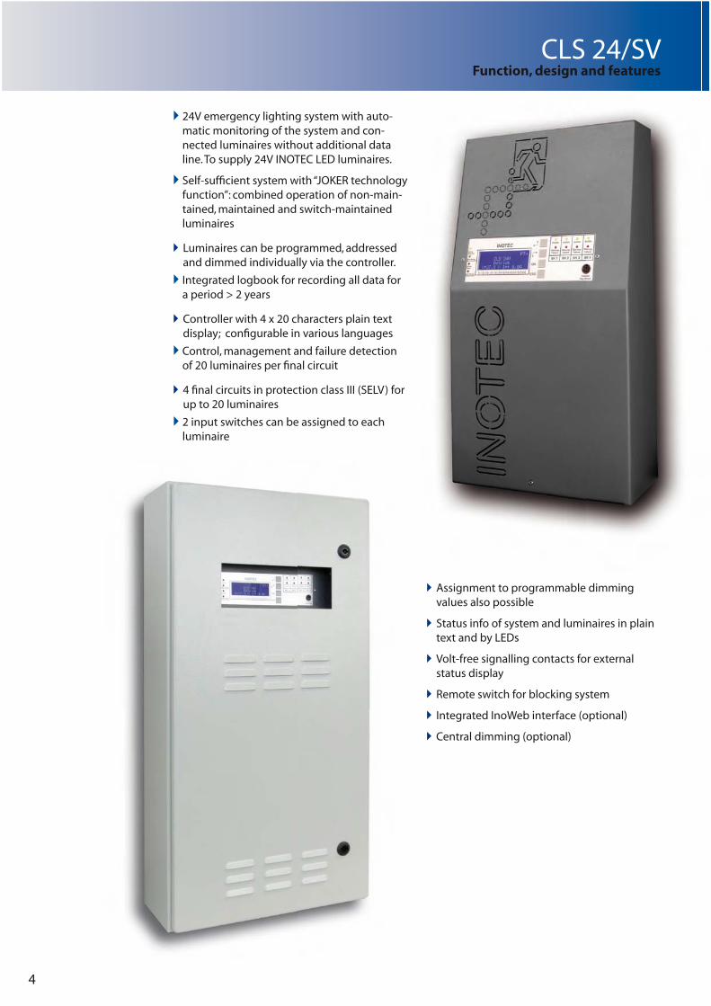
� 24V emergency lighting system with auto-matic monitoring of the system and con-nected luminaires without additional data line. To supply 24V INOTEC LED luminaires.
� Self-suffi cient system with “JOKER technology function”: combined operation of non-main-tained, maintained and switch-maintained luminaires
�� Luminaires can be programmed, addressed and dimmed individually via the controller.
� Integrated logbook for recording all data for a period > 2 years
�� Controller with 4 x 20 characters plain text display; confi gurable in various languages
� Control, management and failure detection of 20 luminaires per fi nal circuit
�� 4 fi nal circuits in protection class III (SELV) for up to 20 luminaires
� 2 input switches can be assigned to each luminaire
CLS 24/SVFunction, design and features
�� Assignment to programmable dimming values also possible
�� Status info of system and luminaires in plain text and by LEDs
�� Volt-free signalling contacts for external status display
�� Remote switch for blocking system
�� Integrated InoWeb interface (optional)
�� Central dimming (optional)
5
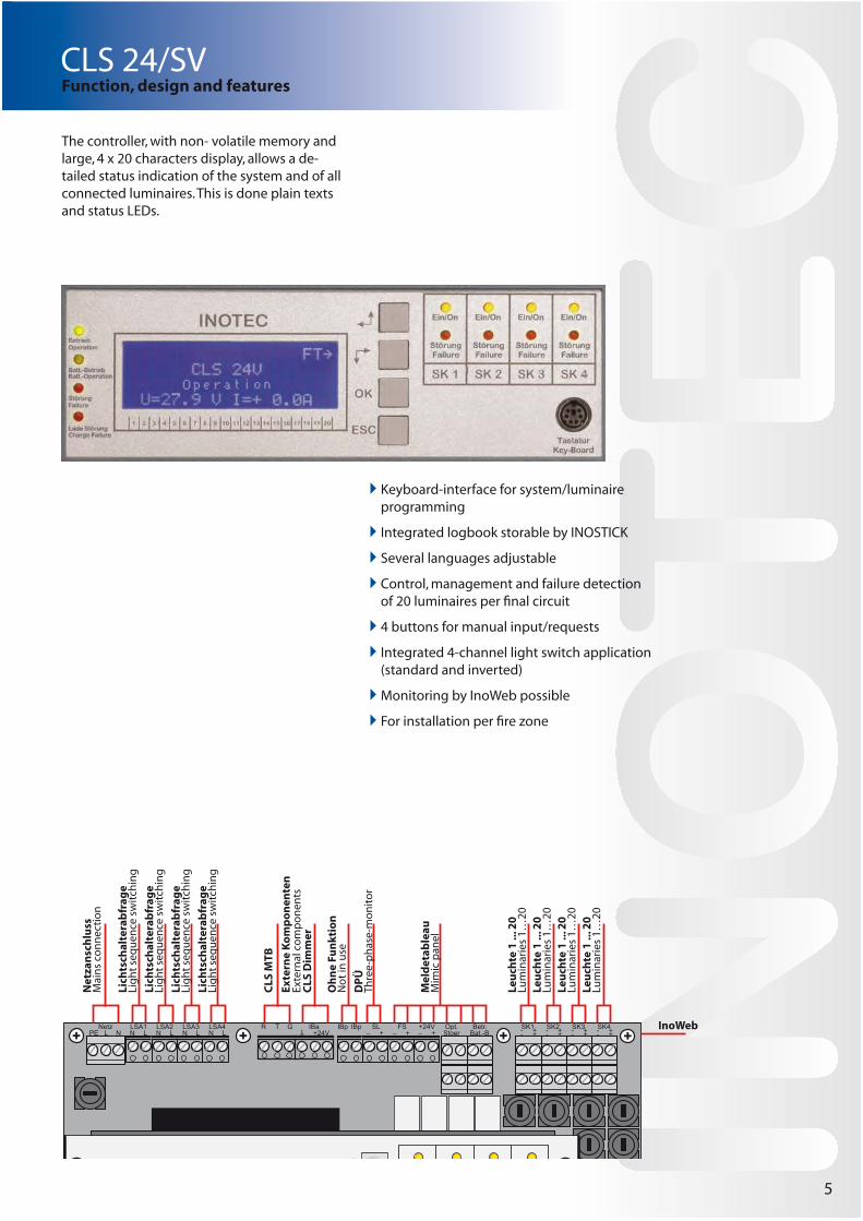
� Keyboard-interface for system/luminaire programming
� Integrated logbook storable by INOSTICK
� Several languages adjustable
� Control, management and failure detection of 20 luminaires per fi nal circuit
� 4 buttons for manual input/requests
� Integrated 4-channel light switch application (standard and inverted)
� Monitoring by InoWeb possible
� For installation per fi re zone
The controller, with non- volatile memory and large, 4 x 20 characters display, allows a de-tailed status indication of the system and of all connected luminaires. This is done plain texts and status LEDs.
CLS 24/SVFunction, design and features
�� �� �����
� �����
� �����
� �����
��� �� � �� ���� ��������
����
� ����� ��
������
�� �� ��
�� ��� �!��
�"�! �! ��"�! �! �
�"�! �! ��"�! �! �
Net
zan
sch
luss
Mai
ns
con
nec
tio
n
Lich
tsch
alte
rab
frag
eLi
gh
t se
qu
ence
sw
itch
ing
Lich
tsch
alte
rab
frag
eLi
gh
t se
qu
ence
sw
itch
ing
Lich
tsch
alte
rab
frag
eLi
gh
t se
qu
ence
sw
itch
ing
Lich
tsch
alte
rab
frag
eLi
gh
t se
qu
ence
sw
itch
ing
CLS
MTB
Oh
ne
Fun
ktio
nN
ot
in u
se
DP
ÜTh
ree-
ph
ase-
mo
nit
or
Mel
det
able
auM
imic
pan
el
Leu
chte
1 ..
. 20
Lum
inar
ies
1…20
Leu
chte
1 ..
. 20
Lum
inar
ies
1…20
Leu
chte
1 ..
. 20
Lum
inar
ies
1…20
Leu
chte
1 ..
. 20
Lum
inar
ies
1…20
InoWeb
Exte
rne
Ko
mp
on
ente
nEx
tern
al c
om
po
nen
tsC
LS D
imm
er

6
CLS 24/SV
By using web technology the central monitoring solution is platform-independent and it’s no longer necessary to install additi-onal software. All systems can be checked with any html-browser, even by portable devices such as smartphones or PDAsAdditional functions:
� Monitoring of up to 491,520 lumi-naires (CPS 220/64 with 128 2-A circuits and 20 luminaires)
� Test for function and battery duration automatically activated at freely defi nable intervals
� Failure printout for all connected devices
� Support of CPS 220/64, CPS 220/48.1 and CLS 24
� Confi guration software (installa-tion required) for system pro-gramming available soon
� Possible to set password to pro-tect access rights
� Overall status is displayed in INOMASTER
INOMASTER, the central monitoring solu-tion for using the RTG-cabeling of INOTEC emergency systems. Up to 192 devices can be operated combined in 6 lines.
�
�
�
�
#���$��
�%�&��
'����(��)'�*��(�)
�%�&��
�%�&��
�%�&��
�
�
�
�
#���$��
�%�&��
'����(��)'�*��(�)
�%�&��
�%�&��
�%�&��
�
�
�
�
#���$��
�%�&��
'����(��)'�*��(�)
�%�&��
�%�&��
�%�&��
�
�
�
�
#���$��
�%�&��
'����(��)'�*��(�)
�%�&��
�%�&��
�%�&��
�
�
�
�
#���$��
�%�&��
'����(��)'�*��(�)
�%�&��
�%�&��
�%�&��
�
�
�
�
#���$��
�%�&��
'����(��)'�*��(�)
�%�&��
�%�&��
�%�&��
�
�
�
�
#���$��
�%�&��
'����(��)'�*��(�)
�%�&��
�%�&��
�%�&��
�
�
�
�
#���$��
�%�&��
'����(��)'�*��(�)
�%�&��
�%�&��
�%�&��
�
�
�
�
#���$��
�%�&��
'����(��)'�*��(�)
�%�&��
�%�&��
�%�&��
�
�
�
�
#���$��
�%�&��
'����(��)'�*��(�)
�%�&��
�%�&��
�%�&��
�
�
�
�
#���$��
�%�&��
'����(��)'�*��(�)
�%�&��
�%�&��
�%�&��
�
�
�
�
#���$��
�%�&��
'����(��)'�*��(�)
�%�&��
�%�&��
�%�&��
�
�
�
�
#���$��
�%�&��
'����(��)'�*��(�)
�%�&��
�%�&��
�%�&��
�
�
�
�
#���$��
�%�&��
'����(��)'�*��(�)
�%�&��
�%�&��
�%�&��
�
�
�
�
#���$��
�%�&��
'����(��)'�*��(�)
�%�&��
�%�&��
�%�&��
�
�
�
�
#���$��
�%�&��
'����(��)'�*��(�)
�%�&��
�%�&��
�%�&��
�,�� �� ���
Netz
�$���� �� �-�.
Ein
10AT16AT
Batterie
�
�
�
�
#���$��
�%�&��
'����(��)'�*��(�)
�%�&��
�%�&��
�%�&��
�
�
�
�
#���$��
�%�&��
'����(��)'�*��(�)
�%�&��
�%�&��
�%�&��
�
�
�
�
#���$��
�%�&��
'����(��)'�*��(�)
�%�&��
�%�&��
�%�&��
�
�
�
�
#���$��
�%�&��
'����(��)'�*��(�)
�%�&��
�%�&��
�%�&��
�
�
�
�
#���$��
�%�&��
'����(��)'�*��(�)
�%�&��
�%�&��
�%�&��
�
�
�
�
#���$��
�%�&��
'����(��)'�*��(�)
�%�&��
�%�&��
�%�&��
�
�
�
�
#���$��
�%�&��
'����(��)'�*��(�)
�%�&��
�%�&��
�%�&��
�
�
�
�
#���$��
�%�&��
'����(��)'�*��(�)
�%�&��
�%�&��
�%�&��
�
�
�
�
#���$��
�%�&��
'����(��)'�*��(�)
�%�&��
�%�&��
�%�&��
�
�
�
�
#���$��
�%�&��
'����(��)'�*��(�)
�%�&��
�%�&��
�%�&��
�
�
�
�
#���$��
�%�&��
'����(��)'�*��(�)
�%�&��
�%�&��
�%�&��
�
�
�
�
#���$��
�%�&��
'����(��)'�*��(�)
�%�&��
�%�&��
�%�&��
�
�
�
�
#���$��
�%�&��
'����(��)'�*��(�)
�%�&��
�%�&��
�%�&��
�
�
�
�
#���$��
�%�&��
'����(��)'�*��(�)
�%�&��
�%�&��
�%�&��
�
�
�
�
#���$��
�%�&��
'����(��)'�*��(�)
�%�&��
�%�&��
�%�&��
�
�
�
�
#���$��
�%�&��
'����(��)'�*��(�)
�%�&��
�%�&��
�%�&��
�,�� �� ���
#������(+�(��",��!��#������(+�(��",��!��
#��
#�� #��
#������(+�(��",
-�$��&��-
-�$��&��-
Central monitoring

CLS 24/SV
�. � .�
��/ �
�01 23
�01 23
#�� #��
#�� #��
Intranet / Company network
7
The emergency lighting devices are monitored by accessing the controller’s INOWEB func-tionality (by means of the web browser). Every system, circuit and luminaire status can be checked by the password-protected (optional) website. It is also possible to monitor systems on a PC with Internet access if an Internet connection is already in place. For demonstration purposes, please contact your regional technical sales
team.
Functions:
� Starting a function test / battery duration test
� Blocking / Releasing
� Failure printout
� Linking of fi les / webpages per fi nal circuit
It is also possible to monitor complex installations containing a range of system types from a single centralised location (using the INOWEB Control software). To perform this process, the CLS 24/SV must be connected to the available network.
CLS 24/SV with integrated INOWEB function for centralised monitoring of the emergen-cy lighting device via the Intranet/Internet. An existing network is used for connection purposes.
��������� �� ������ ���� ��������� ������� � ��� ���� ��������� �� � ������ �������� ����� �������������� �� �� �!�����"!���
INOWEB Control functionalities:
� Monitoring of up to 99 INOTEC emergency lighting devices
� Automatic function/battery duration test
� Logbook function for all connected devices
� Email automatically sent at defi nable intervals in the event of tests or faults
� Overall status displayed (of all systems) by an icon in the task bar
Central monitoring

Technical data: ������������ ������������� ���� �������� ���� ��������
Protection class: I
Protection category: IP20
Perm. ambient temperature
for system: -5°C bis +25°C
for battery: see battery data sheet
Battery: 24V DC
Supply voltage: �4�(��%�������#�5��6%�&�(+�7�
�4�(��%�������#�5��6%�&�(+�7�
�4�(��%�������#�5��6%�&�(+�7�
�4�(��%�������#�5��6%�&�(+�7�
Battery capacity ����3 ����3 ����3 �8��3
max. discharging current
1 h +%+�� +%+�� ���� ����3 h �%�� &%8�� &%8�� ��%+��8 h �%��� �%+�� �%+�� &%���
Final cicuits � � � �max. load per final circuit 3 A 3 A 3 A 3 A
Noise level ca. 40 dB ca. 40 dB
Conductor cross section, max. (mm²):
Supply cable � � � �Final circuits � � � �Data line (RTG) �%& �%& �%& �%&24V monitoring �%& �%& �%& �%&Light switch applica-tion
�%& �%& �%& �%&
Remote switch �%& �%& �%& �%&+24V -Output �%& �%& �%& �%&Voltfree contacts � � � �
Cable inlets
��$�)��&� ��$�)��&�$�)��� �$�)��� �$�)��� �$�)���+�$�)��+ +�$�)��+ +�$�)��+ +�$�)��+
��%�9 �-�:�31.; ��%�9 �-�:�31.; �� ��Weight incl. battery 15 kg 25,7 kg 37,5 kg 56,5 kg
�<�=>���?�1=�:=��01 3�9�.=�>>�>1=�. �2�.?� �
8
253
630
Depth120
25347
0
Depth82
Depth170
400
800
Depth170
400
800
Technical data CLS 24VCLS 24/SV

Max. voltage drop on cable = 3,5V !!! Fuse protection per final circuit: 5AMax. load per final circuit: 3AMax. wire lengths for max. voltage drop of 3,5V:Load Cross section Length
3A 1,5 mm² 49m
2A 1,5 mm² 74m1A 1,5 mm² 147m3A 2,5 mm² 82m2A 2,5 mm² 123m1A 2,5 mm² 245m
Luminaire Equipment Power values
SNP 1216 6 x LED 0.5W 0,125ASNP 1214 4 x LED 0.5W 0,100ASNP 1018SNP 1118SN 8124.1-41SN 9124.1-41SN 804SN 2518
4 x LED 1W 0,200A
SNP 1016SNP 1116SN 6204
3 x LED 1W 0,150A
SN 6114SN 6109SN 6205SNP 7188SNP 7286
2 x LED 1W 0,115A
SNP 7186 SN 8124.1-11SN 9124.1-11 SN 9024
1 x LED 1W 0,080A
SNP 1520 PM, WE LED 0,070ASNP 1520 D, P, S LED 0,130ASNP 1530 PM, WE LED 0,100ASNP 1530 D, P, S LED 0,180A
9
CLS 24/SVTechnical data CLS 24V

10
CLS 24/SVSystem components and options
CLS DimmerCentral Dimming modul
Allows the ceentral dimming of luminaires in
different fi nal circuits. The programmed lumi-
naires can be dimmed in 10% steps from 0%
(luminaire off ) to 100% by using: � integrated push button � external push button � 0-10V control voltage
Ideal for cinemas, theatres and projection rooms.
Perm. temp.: -15°C bis +40°C
EMC protected acc. to EN 55015
Dimension: H =58, W = 17,5, D = 90 (mm)
DPÜ Three Phase Monitor
To detect phase- or circuit failures in general lighting sub-distribution panelsWith volt-free failure indication contact � LED-indication for L1, L2, L3 � free selectable phase connections � 1 change over contact � monitoring low voltage and mains failure in three-phase systems
� also for single-phase monitoringacc. to IEC 255
� for DIN rail mountingFor the connection to INOTEC CLS input sy-stems.
Voltage: 230V/400V AC 50/60 Hz
Threshold: 0,85UN
Perm. temp.: -20°C ... +60°C
EMC protected acc. to EN 55015
Dimension: H =58, W = 17,5, D = 90(mm)
INOSTICK
For programming and saving the CLS device confi guration. This confi guration is simple to create or change in Microsoft Windows using the provided programming software.
System requirements: Microsoft Windows XP, Microsoft Windows Vista
Min. Microsoft.NET Framework 2.0
Min. resolution: 1024 x 768 pixel

CLS 24/SVSystem components and options
230
38
186
MTB
The MTB-remote mimic panel (MTB/AP = wall mounting, MTB/UP = recessed wall-/panel mounting) are used for external status- and failure indication of emergency lighting systems. Furthermore it allows to block the system via the integrated key-switch.
Functions:
Key-switch free programmable for: � maintained and non maintained light ON / OFF
� maintained light ON / OFF
Displayed: � Green LED - operation � Yellow LED - battery operation � Red LED - failure general
Connection to RIF-module of CPS-system; max cable length with 0,5mm² 500m
Voltage: UN= 24V DC +/-10%
Mode: Permanent operation
Temp.-range: -15°C ... +40°C
Protection category: IP30
Housing: Stainless steel/polycarbonate
EMC protection acc. to EN 55015
Wall mounting (MTB/AP).
Recessed wall mounting (MTB/UP):
74
90 58
Betrieb
Notlicht
������
Ein
Aus
Batt.-BetriebStörung
90
58
43
.�/ �&&
��� ��
�+"�����
#����" )�+"�����
������
'�"�*
��!"��� )'�"�*
11
CLS-MTB
For external status and failure indication of up to 16 connected CLS 24 systems using a three-core RTG-BUS (system- / circuit- / luminaire-status). Manual and automatic function and battery duration test is activated centrally at freely defi nable intervals. The status of the emergency lighting systems is displayed via three status LEDs and on the OLED graphic display in clear text. It is also indicated acousti-cally by the integrated buzzer.
Functional displays: � Green LED – Operation � Yellow LED – Battery operation � Red LED – failure (general)
The status of the emergency lighting de-vices can also be signalled by four volt-free contacts:
� Operation � Battery operation � Failure � Free programmable
Current loop to block or unblock the con-nected emergency lighting systems.
EMC protection in acc. with EN 55015

12
INOTEC Sicherheitstechnik GmbHAm Buschgarten 17
D - 59 469 Ense
Tel +49 29 38/97 30-0 Fax +49 29 38/97 30-29
����������������� ���
707
066
A
usg
abe
05/2
011