deformation and flexibility equations aris - nasa · deformation and flexibility equations for...
TRANSCRIPT
s
c
Deformation and Flexibility Equations For Idealized ARIS Umbilicals,
Under Planar End-Loading Conditions
R. David Hampton University of Alabama in Huntsville
023 18 August 2000
Naveed Quraishi OZ3lHardware and So&vare Engineering
OZ/Space Station Payloads Ofice ONlnternational Space Station
R. David Hampton '
https://ntrs.nasa.gov/search.jsp?R=20030064061 2019-03-03T07:55:52+00:00Z
Deformation and Flexibility Equations For Idealized ARIS Umbilicals,
Under Planar End-Loading Conditions
Final Report
NAS/ASEE Summer Faculty Fellowship Program-2000
Johnson Space Center
Prepared By:
Academic Rank:
University & Department:
NASAlJSC
Directorate:
Division:
Branch:
JSC Colleague:
Date Submitted:
Contract Number:
R. David Hampton, Ph.D., P.E.
Associate Professor
University of Alabama in Huntsville Mechanical and Aerospace Engineering Huntsville, Alabama 35899
ONInternational Space Station
OZ/Space Station Payloads Office
OZ3hIardware and Software Engineering
Naveed Quraishi
August 18,2000
NAG 9-867
4- 1
ABSTRACT
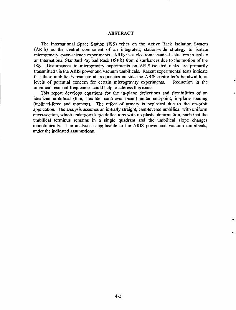
The International Space Station (ISS) relies on the Active Rack Isolation System (ARIS) as the central component of an integrated, station-wide strategy to isolate microgravity space-science experiments. ARIS uses electromechanical actuators to isolate an International Standard Payload Rack (ISPR) from disturbances due to the motion of the ISS. Disturbances to microgravity experiments on ARIS-isolated racks are primarily transmitted via the ARTS power and vacuum umbilicals. Recent experimental tests indicate that these umbilicals resonate at frequencies outside the A R I S controller’s bandwidth, at levels of potential concern for certain microgravity experiments. Reduction in the umbilical resonant frequencies could help to address this issue.
This report develops equations for the in-plane deflections and flexibilities of an idealized umbilical (thin, flexible, cantilever beam) under end-point, in-plane loading (inclined-force and moment). The effect of gravity is neglected due to the on-orbit application. The analysis assumes an initially straight, cantilevered umbilical with uniform cross-section, which undergoes large deflections with no plastic deformation, such that the umbilical terminus remains in a single quadrant and the umbilical slope changes monotonically. The analysis is applicable to the ARIS power and vacuum umbilicals, under the indicated assumptions.
4-2
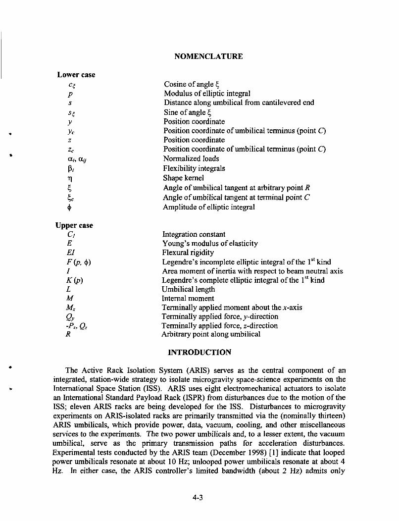
NOMENCLATURE
Lower case CT P
ST Y Yc
ZC
ai, aij Pi
rl 5 5 C
4
S
z
Cosine of angle 5 Modulus of elliptic integral Distance along umbilical from cantilevered end Sine of angle 6 Position coordinate Position coordinate of umbilical terminus (point C ) Position coordinate Position coordinate of umbilical terminus (point C ) Normalized loads Flexibility integrals Shape kernel Angle of umbilical tangent at arbitrary point R Angle of umbilical tangent at terminal point C Amplitude of elliptic integral
Integration constant Young’s modulus of elasticity Flexural rigidity Legendre’s incomplete elliptic integral of the 1 St kind Area moment of inertia with respect to beam neutral axis Legendre’s complete elliptic integral of the 1’‘ kind Umbilical length Internal moment Terminally applied moment about the x-axis Terminally applied force, y-direction Terminally applied force, z-direction Arbitrary point along umbilical
INTRODUCTION
The Active Rack Isolation System (ARIS) serves as the central component of an integrated, station-wide strategy to isolate microgravity space-science experiments on the International Space Station (ISS). ARIS uses eight electromechanical actuators to isolate an International Standard Payload Rack (ISPR) from disturbances due to the motion of the ISS; eleven ARIS racks are being developed for the ISS. Disturbances to microgravity experiments on ARIS-isolated racks are primarily transmitted via the (nominally thirteen) ARIS umbilicals, which provide power, data, vacuum, cooling, and other miscellaneous services to the experiments. The two power umbilicals and, to a lesser extent, the vacuum umbilical, serve as the primary transmission paths for acceleration disturbances. Experimental tests conducted by the ARIS team (December 1998) [ 13 indicate that looped power umbilicals resonate at about 10 Hz; unlooped power umbilicals resonate at about 4 Hz. In either case, the ARIS controller’s limited bandwidth (about 2 Hz) admits only
4-3
limited active isolation at these frequencies. Reduction in the umbilical resonant frequencies could help to address this problem.
Analytical studies of the nonlinear bending and deflection of a flexible cantilever beam (originally horizontal) have been conducted for a variety of loading conditions, including concentrated terminal transverse (vertical) loading [2, 3, 4, 51; uniformly distributed vertical loading [2, 6, 71; uniformly distributed normal loading [8]; concentrated terminal inclined loading [9, lo]; multiple concentrated vertical loads [ 1 11; and concentrated terminal vertical and moment loading [ 1 13. (See the thesis of Christopher Rojahn [ 121 for a thorough summary of the history up to 1968.) Typical exact solutions involve complete and incomplete elliptic integrals [e.g., 2, 11,4,5].
Equations for the case of general terminal in-plane loading (Le., including both inclined-force and moment loads) have apparently not been determined. These and the corresponding in-plane flexibility (or stifhess) equations would be of particular interest toward umbilical design for microgravity-isolation purposes. The equations could be used to help optimize umbilical flexibilities and resonant frequencies for microgravity applications.
This paper develops equations for the in-plane deflections and flexibilities of an idealized umbilical (thin, flexible, cantilever beam) under terminal in-plane loading (inclined-force and moment). The effect of gravity can be neglected due to the on-orbit application. The analysis is applicable to an initially straight, cantilevered umbilical with uniform cross-section, which undergoes large deflections with no plastic deformation, such that the umbilical terminus remains in a single quadrant and the umbilical slope changes monotonically. The analysis would be applicable to the AFUS power and vacuum umbilicals, under the indicated assumptions.
PROBLEM STATEMENT
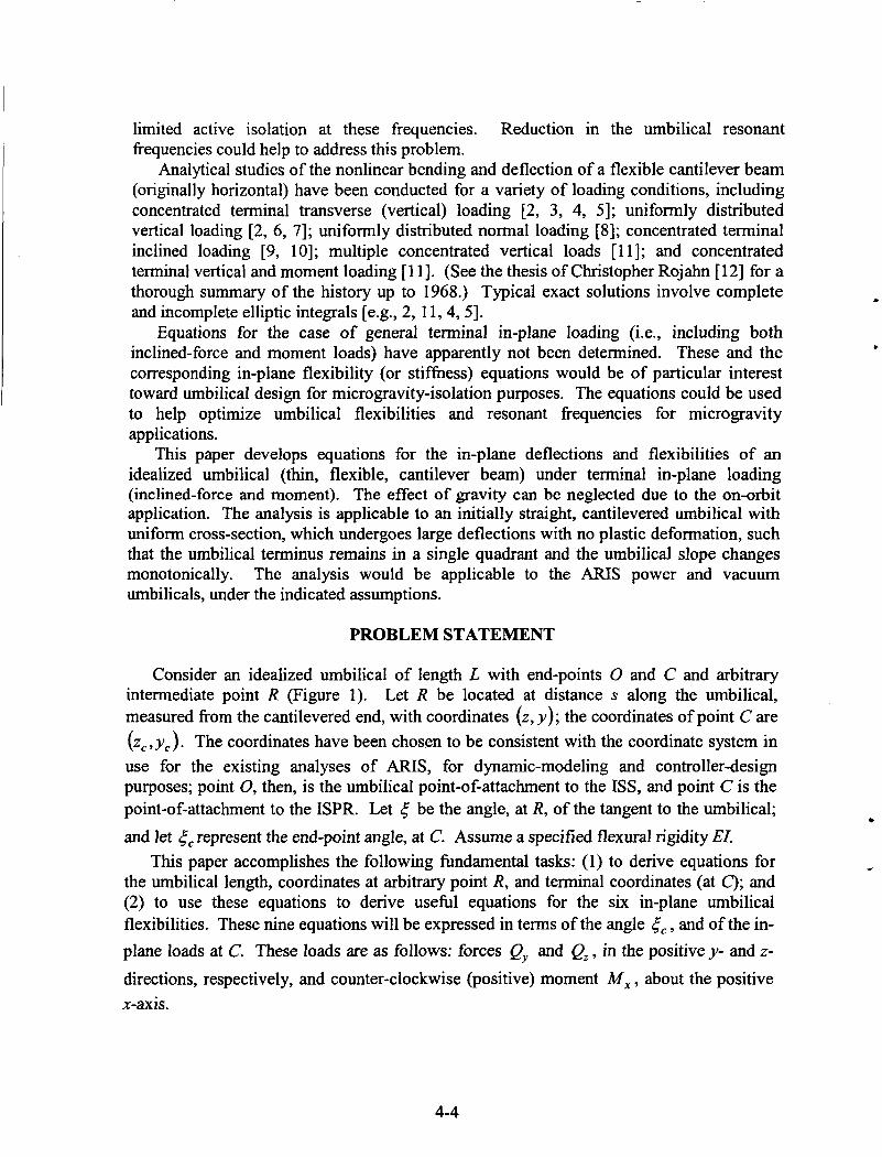
Consider an idealized umbilical of length L with end-points 0 and C and arbitrary intermediate point R (Figure 1). Let R be located at distance s along the umbilical, measured from the cantilevered end, with coordinates (z, y ) ; the coordinates of point C are ( zc ,yc) . The coordinates have been chosen to be consistent with the coordinate system in use for the existing analyses of ARIS, for dynamic-modeling and controller-design purposes; point 0, then, is the umbilical point-of-attachment to the ISS, and point C is the point-of-attachment to the ISPR. Let 5 be the angle, at R, of the tangent to the umbilical; and let 6, represent the end-point angle, at C. Assume a specified flexural rigidity EZ.
T h s paper accomplishes the following hdamental tasks: (1) to derive equations for the umbilical length, coordinates at arbitrary point R, and terminal coordinates (at C); and (2) to use these equations to derive usefbl equations for the six in-plane umbilical flexibilities. These nine equations will be expressed in terms of the angle 5, , and of the in- plane loads at C. These loads are as follows: forces Qy and Q, , in the positive y- and z-
directions, respectively, and counter-clockwise (positive) moment M, , about the positive x-axis.
4-4
Y Figure I. Flexible Umbilical under End Loading
EQUATIONS OF UMBILICAL GEOMETRY
(1) d5 ds
At R the moment equation is M = EI - = M , + Q, (ye - U) - ey (2, - z ) .
dY Differentiating twice, observing that - = -sin 5 ds dz and - = c o s 5 , ds
and using the shorthand notation s5 = sin 5 and cs = cos 6 , one obtains
d25 Q, QY - = -ss +-cs. ds2 EI EI
1 Integration of Equation (4) yields - [ 3) = - (QysF, - Qzcg)+ C, ,
2 ds EI
(4)
where C, is an integration constant. At point C, Equation (1) becomes
4-5
Applying this boundary condition to Equation (9, one has
d5 so that Equation (5) can now be solved for - : ds
2QY where the radicand (9)
Equation (8) applies under the assumption that the radicand 77 is nonnegative, or d5 equivalently, that - is nonpositive. ds
From Equation (8)’ ds = - q - ‘ I 2 4 7
which can be integrated to yield an expression for the umbilical length:
From Equation (2), (12)
so that (13,141
Likewise, Equation (3) yields z = jixq-1’2 ccd5 and z , - - 6 q-1/2ccdc. (15,161
Together, Equations (1 1) and (1 3) through (16) describe the umbilical geometry as functions of the terminal angle 5, ; terminal loads Qy , Q, , and M , ; and integration-, or “shape” kernel 77.
VALIDATION (SPECIAL CASES)
The umbilical geometric equations, (1 1) and (1 3) through (1 6), can be used to derive equations for umbilical in-plane flexibilities. First, however, it will be shown as a check of the mathematics that the geometric equations simplify in some special cases to known forms [ 1 13.
Horizontal Cantilever with Vertical Point Load at Free End
Consider the case where Qy and M , are both zero; this is Frisch-Fay’s “basic strut” [ll,p.41]. Define, for convenience, P, = -e,. (17)
4-6

112
Equation (1 1) becomes
which can be rewritten as L = )-112dc. 2
Let
- and select $I such that
p=sin- 5,
psin9 =sin- 5 2
3 L
1 5 Taking the differential of the above, p cos + d$ = -cos - d{ .
From Equations (20) and (21), sin C - sin 5 = p2 (1 - sin 9);
as 5 varies fiom cc to 2n,+ varies fiom - to n. In this range,
t
2 2 2 5
2 2 n 2
n
so that
/ 2 (24925) -cos+=(1-sin2+r” and -cos-=(l-p2sin2$y 5 ,
2 - ~ P c o s + ~ + dg =
(1 - p2 sin2 +)’” Finally, using Equations (23) and (26) in Equation (19), and simplifying, one obtains the following result:
(27) 1 k L = - W ) 9
where
K ( p ) and F (pl +), respectively, are Legendre’s complete and incomplete elliptic integrals ofthe l”kind[l l ,p . 51.
Horizontal Cantilever with Inclined Point Load at Free End
Consider next the case where Q, and M , are both zero. Equation (1 1) becomes
Introduce + and positive parameterp such that p2 = (1 -sin G,)/ 2
and 112
1-sin5
4-7
Squaring the above yields Taking the differential,
1 -s inc=2p2 sin2 4 . cos<d{ =-4p2 sin@cos@d@,
so that -4p2 sin$cos+
d t = 4 * (I -sin2 {)’I2
From Equation (33) one obtains Equations (33) and (36) together yield
1 + sin 5 = 2(1- p2 sin2 4).
(1 - sin2 = 2 p sin 4 (1 - p2 sin2 + f i 2 .
(33) (34)
. Using Equation (37) in (35) yields As { varies from cc to 27r, 4 vanes from - to - n 1 2 PJZ
- 2 p COS 4 d4 d{ =
(1-p’ sin2 +)’ I2
Obtaining expressions for sin 5 , and sin 5 from Equations (3 1) and (33), respectively, and substituting from these and Equation (35) into Equation (30), one obtains the following result:
where
In terms of elliptic integrals,
112
L = [ E ) [I2(l-p2 sin2+)-’”d$
the solution previously reported in [ 1 11, page 42.
EQUATIONS OF UMBILICAL FLEXIBILITY
The Nature of the Dependencies on Flexural Rigidity EZ
(39)
It will now be shown that, for constant values of L , c,, y , , and z, @e., umbilical
length and terminal geometry), the following expressions are also constants: -, - , and Qy Q, EI E1
- M x . These facts will have important implications for umbilical shapes and flexibilities. EI
Define the following, for two umbilicals (i = 1,2) having the same flexural rigidity and
(42)
terminal angle, but with but different terminal loads: 2 x
Li = L(qi) = I qf1I2d{ > 0, 5c
4-8
and
where
for
(44)
Qy; ali =- EI ’
az j =- EI ’ Qzi (47)
(48) M X i and a3i = -. EI
The terminal angle is assumed to be arbitrary, fixed between x and 2x. Then the following obtains:
(49) ZCI ==c2
The former “if-and-only-if’ statement is true based on the orthogonality of the constant, cosine, and sine functions. As for the latter, using Equation (49,
all = a 1 2 9
a 2 1 = 0 1 2 2 , and (50)
(5 1)
2 2 a31 -a l lS5c -a21ccc = a 3 2 -a12s6c - a 2 2 c 5 c *
2 2
rll(5) = r12 (5) lh 5, 5 2 x e
The third right-hand-side equation will be true if and only if a 3 1 = ~ ~ 3 2 ,
, and - M x are Qy Qz since the first two right-hand-side equations must hold. Since -, - EI EI EI
constants (for fixed umbilical length and terminal geometry), changing the flexural rigidity by some factor y changes all of the terminal loads by the same factor. Further, from Equations (1 3) and (1 5 ) the umbilical shape will also remain unchanged. The implications for in-plane umbilical stifhesses will be explored in the next section.
Basic Flexibility Equations
For given terminal geometry (4 , , yc , and z, ), Leibnitz’ Rule can now be applied to Equations (l l) , (14), and (16) to yield expressions for the six in-plane flexibilities. Applying Leibnitz’ Rule to Equations (14) and (16), one obtains the following initial expressions for the flexibilities:
4-9
and
where
and ~ 1 = c S ~ Q y +scCQz- (59) The partial derivatives on the right-hand-sides of Equations (52) through (57) can be found by applying Leibnitz' Rule to Equation (1 1)' to yield the following:
and
Substituting from Equations (60) through (62) into Equations (52) through (57)' one finally obtains the desired expressions for the flexibilities. For example, substituting from Equation (60) into Equation (52) yields
4-10
Note that the expression in the curly brackets is invariant with EL Corresponding expressions for the other flexibilities can be found in similar manner; each will have a similar form [see Equations (75) through (80) below.] The flexibilities, then, are all inversely proportional to the flexural rigidity.
Simplified Flexibility Equations
For convenience define the following normalized loads and flexibility integrals: Q Y
QZ
011 =-
012 =-
EI ’
EI ’ a3 =-y -M*
a 4 = - = c c1 a + s S c a 2 ,
EI
E1 “ ’
where q = 2a, (sc - sS, )- 2 a 2 (cc - ccc )+ ai. Using these symbols the in-plane flexibility equations are as follows:
4-1 1

and
where a 3 and the square-bracketed expressions are all invariant with EI. This means physically that changing the flexural rigidity by some factor y changes all of the in-plane stiffhesses by the same factor.
IMPLICATIONS FOR UMBILICAL, DESIGN
The foregoing equations can be used as an aid for designing umbilicals to minimize stiffness. First, as previously noted, each of the flexibility equations can be expressed in a form showing it to be inversely proportional to the flexural rigidity [Eqs. (75) through (80) 3. Consequently, reductions in flexural rigidity will produce proportional reductions in all in-plane stiffnesses. Second, it was shown that for a fixed umbilical geometry, changes in flexural rigidity will produce proportional changes in all of the terminal (in-plane) loads. Third, for given umbilical length L, and end-point conditions c,, z, , and y E , Equations (1 l), (14), and (16) can be solved for the loads Qy , Q, , and M , . These loads can be determined and used iteratively in Equations (75) through (80) to maximize umbilical flexibilities (or, equivalently, to minimize the corresponding stiffhesses) using L as a parameter. And fourth, the umbilical designer can use the preceding equations to determine optimal L, 6, combinations. Although the angle 6, is fixed at about 225” for ARIS (in the “home,” or centered, position); L, 6, optimization could suggest better angles for future designs.
CONCLUSION
In summary, this paper presented equations for the shape and flexibility of an umbilical on ,orbit (i-e., such that gravity can be neglected), under terminal in-plane loading conditions of even sufficient magnitude to cause large deformations. The umbilical was assumed to be initially straight, to have a uniform cross-section, and to undergo no plastic deformation. All in-plane stiffhesses were shown to be proportional to the flexural rigidity EI. An approach was offered for using umbilical length and terminal geometry (end-point locations and slopes) to optimize these umbilical stifhesses. The basic equations were shown to reduce to previously published results for special loading conditions.
4-12
REFERENCES
3) 4)
5)
7)
9)
Edberg, Donald L., and Wilson, Bruce W., “Design and Testing of Reduced-Stifiess Umbilicals for Space Station Microgravity Isolation,” AIAA 2000- 1408, Apr. 2000. Hummel, F. H., and Morton, W. B., “On the large deflection of thin flexible strips and the measurement of their elasticity,” Philosophical Magazine, Series 7, Vol. 17, 1927,
Gross and Lehr, Die Federn, Berlin V. D. I. Verlag, 1938. Barten, H. J., “On the deflection of a cantilever beam,” Quarterly of applied Mathematics, Vol. 2, 1944, pp. 168-171; Vol. 3, 1945, pp. 275-276. Bisshopp, K. E., and Drucker, D. C., “Large deflections of cantilever beams,” Quarterly ofApplied Mathematics, Vol. 3, Oct. 1945, pp. 272-275. Bickley, W. G., “The heavy elastica,” Philosophical Magazine, Series 7, Vol. 17,
Rohde, F. V., “Large deflections of a cantilever beam with a uniformly distributed load,” Quarterly ofApplied Mathematics, Vol. 11, 1953, pp. 337-338. Mitchell, T. P., “The non-linear bending of thin rods,” Journal of AppZied Mechanics, Vol. 26, Trans. ASME, Vol81, Series E, 1959, pp. 40-43. Beth, R. A., and Wells, C. P., “Finite deflections of a cantilever strut,” Journal of Applied Physics, Vol. 22, 195 1, pp. 742-746. Massoud, M. F., “On the problem of large deflection of a cantilever beam,” International Journal of Mechanical Sciences, Vol. 8, Feb. 1966, pp. 14 1 - 143. Frisch-Fay, R., Flexible Bars, Butterworth and Co., Limited, Great Britain, 1962. Rojahn, C., “Large Deflections of Elastic Beams,” thesis for the Degree of Engineer, Stanford University, June 1968.
pp. 348-357.
1934, pp. 603-622.
4-13