design analysis deep excavations session01
DESCRIPTION
Design Analysis Deep ExcavationsTRANSCRIPT

November 2009 Excavation Overview
Wong Kai Sin 1
A Short Course on
DEEP EXCAVATIONS
By
WONG Kai Sin
1
November/December 2009
New Zealand
Excavation Overview
Time Session Topic
Session 1 Overview
p09:00 – 10:30 1 Overview10:30 – 11:00 Coffee Break
11:00 – 12:30 2 Design (Part 1)12:30 - 01:30 Lunch
01:30 – 03:00 3 Mohr-Coulomb Soil Model &
2
Design (Part 2)03:00 – 03:30 Coffee Break
03:30 – 05:00 4 How to reduce wall deflection
Excavation Overview

November 2009 Excavation Overview
Wong Kai Sin 2
Overview of Braced Excavation
• Types of walls
•Methods of excavation
•Modes of failure
3Excavation Overview
Anatomy of a Braced Excavation
struts
wall
walers
walers
struts
kingposts
4
wall
Excavation Overview

November 2009 Excavation Overview
Wong Kai Sin 3
Types of Retaining Walls for Excavation
5
Cantilever Wall Anchored or Propped Wall
Braced Wall
Excavation Overview
Wall Types of Deep Excavations
Diaphragm WallDiaphragm Wall
Sheetpile Wall
Bored Pile Wall
Soldier Pile Wall
6
DCM or Grout Mixed Pile Wall
Excavation Overview

November 2009 Excavation Overview
Wong Kai Sin 4
7Excavation Overview
8Excavation Overview

November 2009 Excavation Overview
Wong Kai Sin 5
Concrete Diaphragm Wall
9
Stop‐ends & water‐proofs
Excavation Overview
10Excavation Overview

November 2009 Excavation Overview
Wong Kai Sin 6
Braced Excavation with Sheetpile Wall
struts
wall
walers
walers
struts
kingposts
11
wall
Excavation Overview
Sheetpile Installation
12Excavation Overview

November 2009 Excavation Overview
Wong Kai Sin 7
Bored Pile Walls
13
Contiguous Bored Pile Wall Secant Bored Pile Wall
Excavation Overview
18.5m Cantilever CBP wall at NUS
Contiguous Bored Pile Wall
14Excavation Overview

November 2009 Excavation Overview
Wong Kai Sin 8
Construction of Secant Bored Pile Wall
15Excavation Overview
Braced Excavation with Soldier Pile Wall
16Excavation Overview

November 2009 Excavation Overview
Wong Kai Sin 9
Construction of DCM or Grout Mixed Pile Wall
17Excavation Overview
Grout Mixed Pile Wall
18Excavation Overview

November 2009 Excavation Overview
Wong Kai Sin 10
struts
wall
walers
walers
walers
struts
wall
kingposts
Conventional Bottom‐Up
19
wallBottom‐Up Excavation Method
Excavation Overview
Top‐Down Excavation
20Excavation Overview

November 2009 Excavation Overview
Wong Kai Sin 11
Top‐Down Excavation at Boon Keng Station
21Excavation Overview
Up‐Down Construction Method
22Excavation Overview

November 2009 Excavation Overview
Wong Kai Sin 12
Up‐Down Construction Method
23Excavation Overview
Island Method of Excavation
24Excavation Overview

November 2009 Excavation Overview
Wong Kai Sin 13
Under Water Excavation
atat
Marina South
25Excavation Overview
26Excavation Overview

November 2009 Deformation & Failure Modes
Wong Kai Sin 1
Wall and Ground Movements in Excavation
FILL
MARINE CLAY
200 to 300 m
Damage ?? Damage ??Damage ??
1
OLD ALLUVIUM
SAND
Deformation & Failure Modes
Main Cause of Wall DeflectionUndrained Shear Distortion in Clay
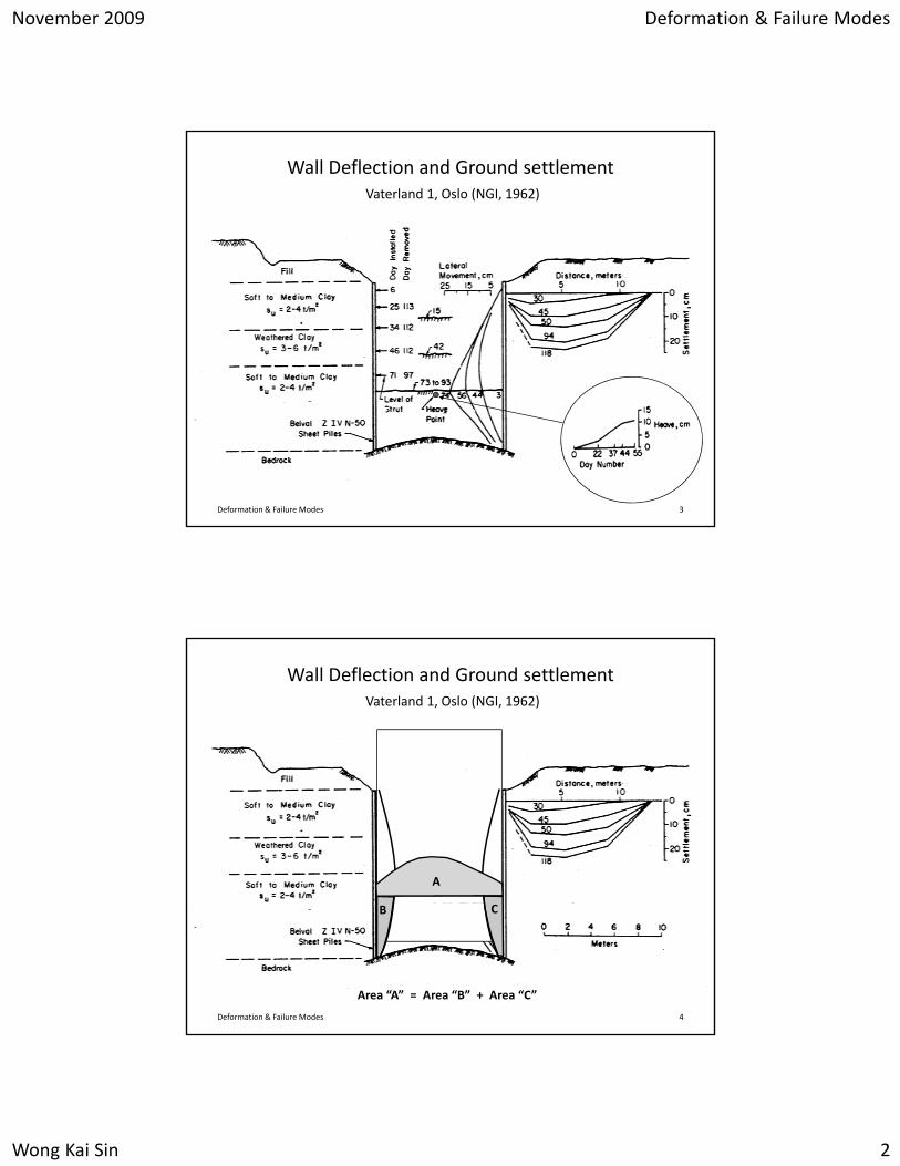
Vaterland 1, Oslo (NGI, 1962)
Ad
As
2
No volume change!
Ad ~ As
Ad
As
Deformation & Failure Modes
November 2009 Deformation & Failure Modes
Wong Kai Sin 2
Wall Deflection and Ground settlementVaterland 1, Oslo (NGI, 1962)
3Deformation & Failure Modes
Wall Deflection and Ground settlementVaterland 1, Oslo (NGI, 1962)
A
4
B C
Area “A” = Area “B” + Area “C”
Deformation & Failure Modes
November 2009 Deformation & Failure Modes
Wong Kai Sin 3
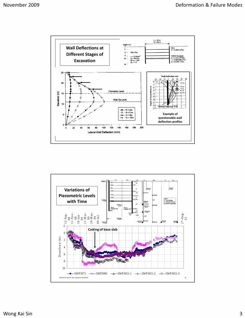
Wall Deflections at Different Stages of
Excavation
Deformation & Failure Modes 5
Example of questionable wall deflection profiles
Variations of Piezometric Levels
with Time
-2
0
2
4
12-S
ep-
9811
-Nov
-98
10-J
an-
9911
-Mar
-99
10-M
ay-
9909
-Jul
-99
07-S
ep-
9906
-Nov
-99
05-J
an-
0005
-Mar
-00
04-M
ay-
0003
-Jul
-00
01-S
ep-
0031
-Oct
-00
30-D
ec-
0028
-Feb
-01
29-A
pr-
0128
-Jun
-01
27-A
ug-
01
wn
(m)
Casting of base slab
Deformation & Failure Modes 6
4
6
8
10
Dra
wdo
w
GWP3071 GWP3081 GWP3051-1 GWP3051-2 GWP3051-3

November 2009 Deformation & Failure Modes
Wong Kai Sin 4
Development of Strut Forces during Excavation
7Deformation & Failure Modes
Development of Strut Forces during Excavation
8Deformation & Failure Modes

November 2009 Deformation & Failure Modes
Wong Kai Sin 5
9Deformation & Failure Modes
Development of Bending Moment During Excavation
Deformation & Failure Modes 10

November 2009 Deformation & Failure Modes
Wong Kai Sin 6
Major Factors Affecting Soil and Wall Movements in Deep Excavations
• Depth of penetration, D• Undrained shear strength, cu
11
p p ,
•Wall stiffness, EI
• Vertical strut spacing
• Construction workmanship
g , u
• Depth of excavation, H
•Width of excavation, B
• Depth to hard stratum, T
Deformation & Failure Modes
Effect of Shear Strength on Wall
Deflection
12Deformation & Failure Modes

November 2009 Deformation & Failure Modes
Wong Kai Sin 7
Effect of Shear Strength on Wall
Deflection
13Deformation & Failure Modes
Effect of Excavation Width
on Wall Deflection
14Deformation & Failure Modes

November 2009 Deformation & Failure Modes
Wong Kai Sin 8
Effect of Clay Thickness on Wall
Deflection
15Deformation & Failure Modes
Sheetpile wall
Diaphragm wall
Effect of Wall Stiffness on Wall
Deflection
wall wall
16Deformation & Failure Modes

November 2009 Deformation & Failure Modes
Wong Kai Sin 9
Modes of Failure
Collapse Excessive Deformation
17Deformation & Failure Modes
Basal Heave Stability
qo
qult
18
When qo > qult, failure in imminent.
Deformation & Failure Modes

November 2009 Deformation & Failure Modes
Wong Kai Sin 10
Basal Heave Failure in Taipei
19Deformation & Failure Modes
Basal Heave Failure due to Stockpiling
Excessive Surcharge
q = 20 kPa
20Deformation & Failure Modes

November 2009 Deformation & Failure Modes
Wong Kai Sin 11
Basal Heave Failure due to Stockpiling
Stockpile
21Courtesy of Dr Lim PC
Deformation & Failure Modes
Basal Heave Stability
Wall Rotation
22Deformation & Failure Modes

November 2009 Deformation & Failure Modes
Wong Kai Sin 12
Basal Heave Stability
Wall Raking
23Deformation & Failure Modes
Basal Heave Stability
Lifting of King Posts
Jet Grout Slab
24Deformation & Failure Modes

November 2009 Deformation & Failure Modes
Wong Kai Sin 13
Lifting of Kingpost due to Bottom Heave
25Deformation & Failure Modes
Basal Heave Stability
Not all basal heave instability lead to catastrophic failures
26
Formation Level
Deformation & Failure Modes

November 2009 Deformation & Failure Modes
Wong Kai Sin 14
Piping &
Loss of Fines
27Deformation & Failure Modes
Strut Failure
28Deformation & Failure Modes

November 2009 Deformation & Failure Modes
Wong Kai Sin 15
Strut Failures
29Deformation & Failure Modes
Effect on Adjacent StructuresStructures
30Deformation & Failure Modes

November 2009 Deformation & Failure Modes
Wong Kai Sin 16
Effect of Excessive Movements
Damaged Pavement
31
After Choong (2003)
Deformation & Failure Modes
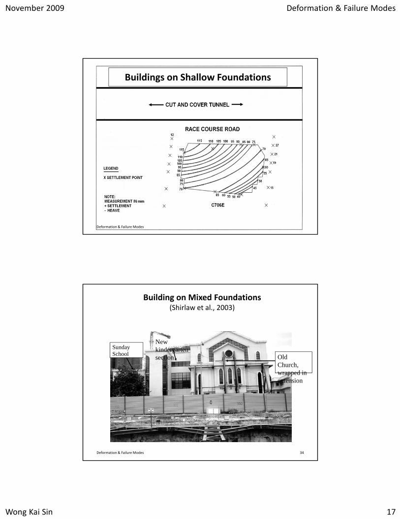
Buildings on Shallow Foundations
32
Race Course Road
Deformation & Failure Modes
November 2009 Deformation & Failure Modes
Wong Kai Sin 17
Buildings on Shallow Foundations
33Deformation & Failure Modes
Building on Mixed Foundations(Shirlaw et al., 2003)
NewSundaySchool
New kindergarten section Old
Church, wrapped in extension
34Deformation & Failure Modes

November 2009 Deformation & Failure Modes
Wong Kai Sin 18
Building on Mixed Foundations
35Deformation & Failure Modes
Lowering of Ground Water Table
Causes:
Pumping
Well pointWell point
Pumping
Wall leakage Sand
Marine Clay
36
Old Alluvium
Lowering of ground water table will increase the effective stress in soft clay and result in consolidation settlement.
Deformation & Failure Modes

November 2009 Deformation & Failure Modes
Wong Kai Sin 19
Effect of Lowering of Groundwater Table
37Deformation & Failure Modes
38Deformation & Failure Modes

November 2009 Observational Method
Wong Kai Sin 1
Observational Approach in Deep Excavation
Design
1
ConstructionMonitoring
Obervational Method
In a perfect world …….
All we need is one analysis & one design!
2Obervational Method

November 2009 Observational Method
Wong Kai Sin 2
In the imperfect world …. with imperfect design!
Too many uncertainties:
• Soil conditionsSoil conditions
• Ground water
• Loading
• Construction sequence
• Workmanship
• Time delayNot easy to account for all
3
y
• 3‐D effect
• Proficiency of designer
• Limitations of software
these uncertainties in the design.
Obervational Method
In the imperfect world …….
•Watch every steps carefully.
Design
•Make adjustments when necessary.
• Improvise as excavation proceeds.
4
ConstructionMonitoring
Obervational Method

November 2009 Observational Method
Wong Kai Sin 3
Role & Responsibility
Design
ConstructionMonitoring
Team Role and Responsibility
Design • Produce a good design• Monitor performance of system• Modify design
C t ti B ild di t d i
g
5
Construction • Build according to design• Monitor performance of system• Feedback problems & unusual findings
Monitoring • Install and monitor instruments• Feedback problems & unusual findings
Obervational Method
What is Observational Approach?
It is a check‐and‐balance process that enable us to:
• Check adequacy of the design• Anticipate potential problems • Modify the design where necessary• Optimise the design
6
• Make contingency plan• Avoid unnecessary delay
Obervational Method

November 2009 Observational Method
Wong Kai Sin 4
An Example on Application of Observational Method
(9th Rankine Lecture by R. B. Peck, 1969)
Peck’s APD
7
Design
Obervational Method
Predict Modify Design
Implementation of Observational Approach
0
5
0 20 40 60 80 100
Wall Deflection (mm)
Excavate
Monitor
Compare
Design
Re‐analyse
8
5
10
15
20
25
30
Dep
th (m
)
Compare
Back‐analyseFavourable?Yes No
Obervational Method

November 2009 Observational Method
Wong Kai Sin 5
Designer, Contractor and Instrumentation Specialist have to work together!
Predict Modify Design
Excavate
Monitor
Compare
Design
Re‐analyse0
5
0 20 40 60 80 100
Wall Deflection (mm)
Computed
9
Compare
Back‐analyseFavourable?Yes No
10
15
20
25
30
Dep
th (m
)
Measured
Alert LevelObervational Method
Back‐Analysis: To calibrate input parameters to produce reasonable agreement with field measurements.
Predict Modify Design
Excavate
Monitor
Compare
Re‐analyse
00 20 40 60 80 100
Wall Deflection (mm)
10
Back‐analyseFavourable?Yes No
5
10
15
20
25
30
Dep
th (m
) Computed
Measured
Design
Back‐Analyzed
Obervational Method

November 2009 Observational Method
Wong Kai Sin 6
Predict
Excavate
Modify Design
Re‐Analysis: Use calibrated parameters to re‐analyse
0
5
10
0 20 40 60 80 100
Wall Deflection (mm)
(m)
Excavate
Monitor
Compare
Re‐analyse
15
20
25
30
Dep
th (
0
5
0 20 40 60 80 100 120
Wall Deflection (mm)
11
Back‐analyseFavourable?Yes No10
15
20
25
30
Dep
th (m
)
Obervational Method
Designing Temporary Work is a Continuous Process
Design &Analysis
ConstructionControl
InstrumentationMonitoring
Initial Design Final Design
12
(Work Drawings) (As‐Built)
Start Finish
Excavation
Obervational Method

November 2009 Site Investigation
Wong Kai Sin 1
Site Investigation
Site Investigation 1
How many borings should we drill?
In general, the more the merrier!
It depends on ho m ch e kno abo t the site and theIt depends on how much we know about the site and the nature of project. It is a very subjective decision.
Be careful of “Penny Wise but Dollar Foolish”!
Site Investigation 2

November 2009 Site Investigation
Wong Kai Sin 2
Problem of having too few borings
Site Investigation 3
Boring 1 Boring 2
Problem of having too few borings
Bedrock
Unforeseen Ground Conditions?
Site Investigation 4

November 2009 Site Investigation
Wong Kai Sin 3
Surprise!
Site Investigation 5
$$$
Problem of having too many borings
S.I. will take a long time
Tight schedule affects quality
Multiple drillers and multiple laboratories
Design completed ahead of S.I.
BCA’s Advisory Note: 1 boring every 300 m2.
Site Investigation 6

November 2009 Site Investigation
Wong Kai Sin 4
Site Investigation
Which one is better practice?
[B] 45 borings [A] 15 borings
Site Investigation 7
Site Investigation
150 m
How many borings? Where?
90 m
BCA’s Advisory Note: 1 boring every 300 m2.
Therefore, 45 borings over 13,500 m2.Site Investigation 8

November 2009 Site Investigation
Wong Kai Sin 5
Site Investigation
150 m
It is better to conduct it in phases!
90 m
Phase 1 Phase 2 Phase 3
Site Investigation 9
FillEE
Fill
Control Section for Construction Control
Control Section E
UMC
F2 upper
LMC
F2 lowerF2
LMC
LMC
OA N = 20
F2 upper
UMC
E
JGP1
JGP2
Section
F2 lower
OA N = 20OA N = 30
OA N = 70
OA N = 100OA N = 70OA N = 30OA N = 20
JGP2
Additional borings at Control Section!
Site Investigation 10

November 2009 Site Investigation
Wong Kai Sin 6
Site Investigation
Type of soil sampler
SPT split‐barrel
Shelby tube
Piston
M i
Type of in‐situ tests
SPT
FVT
CPT
P tMazier
Thick‐walled tube
Pressuremeter
Permeability
The Designer must instruct the driller what to do!Site Investigation 11
Undrained Shear Strength of Clay cu
Laboratory Tests(Undisturbed Samples)
In‐Situ Tests
FVTUCUUCUCKoUTCCKoUTECK UDSS
SPTCPTPMTDMT
Each test gives a CKoUDSSMiniature VaneConeTorvanePocket Penetrometer
gdifferent cu!
Which test should we do?
Site Investigation 12

November 2009 Site Investigation
Wong Kai Sin 7
What should we do with the Factual Reports?
Site Investigation 13
Scrutinize the test results
Test A Test B
cu= 40 kPaφu = 0
cu= 28 kPaφu = 0
Which one is more reliable?Site Investigation 14

November 2009 Site Investigation
Wong Kai Sin 8
Proper way of trimming soil sample
Site Investigation 15
An expedient way to “trim” a sample
How to prepare a “disturbed” sample?!
Site Investigation 16

November 2009 Site Investigation
Wong Kai Sin 9
You get what you paid for!
Site Investigation 17
Trimmed Sample Untrimmed Sample
UU CU
Mazier Samples
Site Investigation 18
November 2009 Site Investigation
Wong Kai Sin 10
0
10
0 20 40 60 80 100 120 140 160
Cu from UU Tests (kPa)
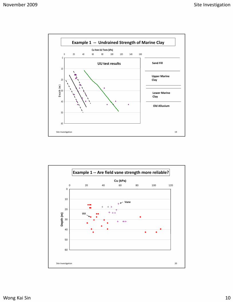
UU test results
Example 1 ‐‐ Undrained Strength of Marine Clay
Sand Fill
10
20
30
40
Dep
th (m
)
Upper Marine Clay
Lower Marine Clay
40
50
60
Old Alluvium
Site Investigation 19
Example 1 ‐‐ Are field vane strength more reliable?
0
10
0 20 40 60 80 100 120
Cu (kPa)
10
20
30
40
Dep
th (m
)
Vane
UU
50
60
Site Investigation 20

November 2009 Site Investigation
Wong Kai Sin 11
How do we differentiate between good and bad data?
i h dibl ?
0
0 20 40 60 80 100 120
Cu (kPa)
M t I dibl ?Highest Incredible?
10
20
30
Dep
th (m
)
Vane UU
Most Incredible?
Fully consolidated
Before reclamation
Worst Incredible?
40
50
60
Site Investigation 21
Example 1 ‐ Results of field vane tests from two companies
0
5
0 20 40 60 80 100 120
Cu (kPa)
S dfill
0
5
0 20 40 60 80 100 120
Cu (kPa)
5
10
15
20
25
30
35
Dep
th (m
)
Sandfill
Marine Clay
5
10
15
20
25
30
35
Dep
th (m
)
Sandfill
Marine Clay
35
40
45
50Old Alluvium
Company B
35
40
45
50Old Alluvium
Company A
Site Investigation 22

November 2009 Site Investigation
Wong Kai Sin 12
Data from Company A
Data from Company B
Should we engage another company for 3rd opinion?
Should we use the average values from A and B?
Site Investigation 23
Example 2 – cu from CPTU
Site Investigation 24

November 2009 Site Investigation
Wong Kai Sin 13
0
10
0 20 40 60 80 100 120
Undrained Shear Strength (kPa)
CPT-1Contractor
(qt – σv)cu = ‐‐‐‐‐‐‐‐‐‐‐‐‐
NktContractor
20
30
40
Dep
th (m
)
AC - Nk=12
Client - Nk=20
Consultant A Nkt=12
C lt t C N 20
Vane
Must calibrate cone factor “Nkt” against other data
50
60
AC - Nk=14Client - Nk=20
Consultant B Nkt=14Consultant C Nkt=20
Site Investigation 25
p’o & p’c (kPa)
0
5
0 50 100 150 200 250 300 350 400
P'c from Consol
P'o
0
5
0 10 20 30 40 50 60 70 80
Cu (kPa)
BH3-UUBH3-vaneBH3-consolBH4-consol0.22*P'oBH4-UU
cu (kPa)
Example 3 ‐‐ parameters from a uniform soil deposit
10
15
20
25
30
Dep
th (m
)
10
15
20
25
30
Dep
th (m
)
BH4-vaneBH1-vaneBH2-vaneBH1-UUBH2-UU
35
40
If all data fall within a narrow band, we can use the best fitting curve for the entire site.
30
35
40
Data from entire siteData from entire site
Site Investigation 26
November 2009 Site Investigation
Wong Kai Sin 14
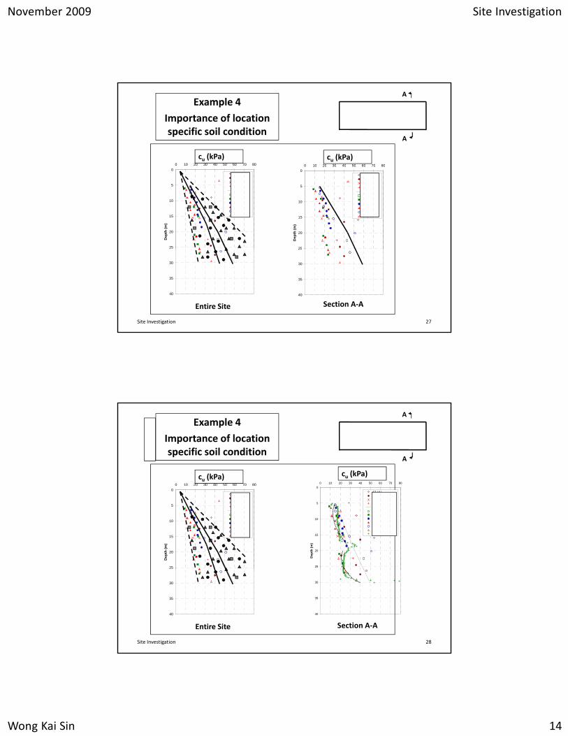
Example 4
Importance of location specific soil condition
0 10 20 30 40 50 60 70 80
Cu (kPa)cu (kPa)
0 10 20 30 40 50 60 70 80
Cu (kPa)
A
A
cu (kPa) 0
5
10
15
20
25
Dep
th (m
)
BH3-UUBH3-vaneBH3-consolBH4-consol0.22*P'oBH4-UUBH4-vaneBH1-vaneBH2-vaneBH1-UUBH2-UU
0
5
10
15
20
25
0 10 20 30 40 50 60 70 80
Dep
th (m
)
BH3-UUBH3-vaneBH3-consolBH4-consol0.22*P'oBH4-UUBH4-vaneBH1-vaneBH2-vaneBH1-UUBH2-UU
30
35
40
Entire Site
25
30
35
40
Section A‐A
Site Investigation 27
A
A
0 10 20 30 40 50 60 70 80
Cu (kPa)cu (kPa)
0 10 20 30 40 50 60 70 80
Cu (kPa)cu (kPa)
Example 4
Importance of location specific soil condition
0
5
10
15
20
25
Dep
th (m
)
A3-UUA3-vaneA3-consolA4-consol0.22*P'oA4-UUA4-vaneM2081-vaneM2081A-vaneM2081-UUM2081A-UUCPT-CR4-Nkt=30
0
5
10
15
20
25
Dep
th (m
)
BH3-UUBH3-vaneBH3-consolBH4-consol0.22*P'oBH4-UUBH4-vaneBH1-vaneBH2-vaneBH1-UUBH2-UU
Section A‐A
30
35
40
30
35
40
Entire Site
Site Investigation 28

November 2009 Site Investigation
Wong Kai Sin 15
10
11
12
13
14
15
16
17
18
0 20 40 60 80 100 120 140 160 180 200 220 240
Effective Stress (kPa)
Dep
th (m
)
Example 5
Importance of location specific soil condition at
a reclaimed site
10
11
12
13
14
0 40 80 120 160 200 240 280
Effective Stress (kPa)
)
19
20
21
22
po'
CPT1
UU-BH1
consol - BH1Fill
Soft Clay
Silty Sand / Sandy Silt15
16
17
18
19
20
21
22
Dep
th (m
)
po'
CPT2
UU - BH2
Stress and strength of soft clay at
reclaimed site can be very variable.
Site Investigation 29
Example 6 ‐‐ Reliability of SPT blowcount in sand
Fill
Marine Clay
F1 N = 2 EquivalentOld
Alluvium
F1 N = 2 Equivalent N~10
Site Investigation 30