design and implementation of a sensor-based wireless ...byan/files/camera-jpuc10.pdfsystem for...
TRANSCRIPT

ORIGINAL ARTICLE
Design and implementation of a sensor-based wireless camerasystem for continuous monitoring in assistive environments
Nan Li • Bo Yan • Guanling Chen •
Prabhu Govindaswamy • Jie Wang
Received: 31 December 2008 / Accepted: 5 October 2009 / Published online: 26 February 2010
� Springer-Verlag London Limited 2010
Abstract Camera-based surveillance system is an
important tool for assistive environment to monitor those
who may have physical or cognitive impairment. It is,
however, expensive to deploy a wired surveillance system
and difficult to continuously monitor a moving subject in a
large facility where many cameras are deployed. In this
paper, we first evaluate the performance of streaming
camera images over wireless networks in both residential
and office environments and present the quantitative results
to show the feasibility of using wireless backbones for
camera surveillance systems. We then propose sensor-
integrated camera surveillance (SICS) to address the con-
tinuous monitoring problem. SICS uses wearable wireless
sensors to locate moving subjects and automatically selects
the camera covering the subject, allowing human operators
to focus on only one screen to monitor an individual. SICS
uses a self-organizing wireless mesh network to allow
flexible deployment at reduced cost. An on-board image-
processing algorithm is used to reduce the bandwidth
consumption. Through empirical evaluation, we found that
the automatic camera hand-off enabled by SICS was
effective for continuous camera monitoring and a sophis-
ticated wireless network management system is required to
deploy the SICS in practice.
Keywords Wireless camera networks �Continuous monitoring � Sensor-based localization
1 Introduction
Our society is facing the aging of population, where an
increasing proportion of people are over the age of 65 [1].
About 12.4% of the population are older Americans. More
than half of the older population (52%) reported having at
least one disability of some types, almost 37% of older
persons reported a severe disability, and 16% reported that
they needed some types of assistance [2]. It is thus
important to provide pervasive and intelligent technologies
to assist those with physical or cognitive impairment, to
improve their quality of life and to meet their special
personal needs [3].
Camera-based surveillance is an ideal technology that
provides most direct and effective visual information to
assist the nursing carers. The global market for video sur-
veillance system is expected to have strong growth,
reaching more than $9 billion by 2011, as security sur-
veillance and remote healthcare become more focused on
communities and households [4]. In those systems, to
continuously monitor certain individuals is one of impor-
tant features, such as to monitor the patients with Alzhei-
mer diseases or the seniors who may frequently fall to the
ground.
It is, however, particularly difficult to provide continu-
ous visual monitoring of individuals in a large facility
where hundreds of cameras are deployed. As the monitored
N. Li (&) � B. Yan � G. Chen � J. Wang
Computer Science Department, University of Massachusetts
Lowell, Lowell, MA, USA
e-mail: [email protected]
B. Yan
e-mail: [email protected]
G. Chen
e-mail: [email protected]
J. Wang
e-mail: [email protected]
P. Govindaswamy
Qualcomm, San Diego, USA
e-mail: [email protected]
123
Pers Ubiquit Comput (2010) 14:499–510
DOI 10.1007/s00779-009-0271-2
subject moves around over different camera coverage
areas, the operator has to manually figure out the current
camera screen that may cover that subject and get a visual
confirmation that the subject does show up on that camera.
This is certainly a tedious and slow task for the operator
given potentially hundreds of camera screens. When the
health carer monitors a large number of mobile users, she
could miss the best chance to help the subject. Simply
increasing the number of operators, each watching some
number of cameras, will not solve the problem since they
have to cooperate to track certain individuals.
In addition, deploying a wired camera network often
requires high installation cost due to laying out network
cables for IP cameras or coax cables for closed-circuit
television (CCTV) cameras. For example, a recent 600-
camera deployment to monitor parking lots cost more than
$8,500 per camera [5]. To deploy a wireless network
instead of wired could be one solution to reduce the
deployment cost. Existing IEEE 802.11 standards
(802.11a/g) can support 54 Mbps data transfer and the
recently ratified 802.11n can support more than 108 Mbps
bandwidth, which means that high-quality sequence images
or video transmission over wireless links is feasible today.
However, the challenge of a wireless camera network is its
relatively lower bandwidth compared to the wired back-
bone, which can be problematic if many cameras need to
share the same link. The increased network density may
also result in more channel contention, hidden terminals,
and capture effect that can significantly degrade network
performance [6].
In this paper, we first present an empirical measurement
study on the performance of using wireless networks to
support distributed camera applications in both residential
and office environment. We focus on indoor environments,
such as large households, office buildings, hospitals, and
senior care centers. Based on these quantitative results, we
propose sensor-integrated camera surveillance (SICS), a
system that implements automatic camera hand-off based
on wireless mesh network. SICS allows the human operator
to only watch a single screen to track one subject as she
moves around. The images of this screen are dynamically
changed based on which camera is covering the monitored
subject. The subject wears a small wireless sensor that
provides the location information for camera selection. The
automatic camera hand-off transforms traditional surveil-
lance model from watching a location covered by a camera
to watching a moving subject covered by many cameras. It
also is possible to integrate other indoor localization
technologies with SICS, such as tags based on RFID [7],
infrared [8], 802.11 [9], or UWB [10]. In an assistive
environment, however, a subject may already wear a sensor
that constantly monitors her vital signs [11], making SICS
appealing for this application.
To the best of our knowledge, the performance evalua-
tion is one of the first quantitative studies focusing on
wireless camera networks and SICS is the first system that
combines wireless mesh for flexible camera deployment,
on-board image analysis for reduced bandwidth consump-
tion, and sensor integration for subject tracking. All the
hardware devices used in this study, including wireless
routers, camera and wireless sensors, are off-the-shelf
devices. Our contributions include:
• the first measurement study of wireless camera net-
works deployed both in a residential and an office
environment;
• the feasibility demonstration of wireless sensor-based
localization for surveillance systems;
• quantitative performance evaluation of automatic cam-
era hand-off through an empirical implementation of
the SICS architecture;
• In the remainder of this paper, we present the related
work in Sect. 2. The system design is presented in Sect.
3. All evaluation results are described in Sect. 4. We
discuss further challenges and summarize in Sects. 5
and 6, respectively.
2 Related work
The related work can be separated into two categories. The
first category focuses on wireless measurement. Papa-
giannaki et al. [12] studied wireless networks in a home
setting, focusing on the MAC and network performance.
They assumed that the applications over the networks are
general, did not focus on surveillance related applications.
Das et al. [13] measured a 32-node outdoor mesh network,
highlighting latency and jitter problems for streaming
applications. Some projects, such as MAP [14], and Jigsaw
[15], applied distributed wireless sniffers to monitor net-
work traffic and measure the wireless network performance
by merging the distributed traces. Most of research in this
area focuses on MAC and network layer behaviors. On the
other hand, we studied the application layer quality, image
transmission performance, over wireless networks in two
typical indoor environments, to demonstrate feasibility of
SICS.
In the second category, the researchers built real wire-
less camera networks with various characteristics. Cyclops
[16] and XYZ [17] developed several prototypes with
camera modules directly mounted on wireless sensor
platforms. These low-cost camera sensor systems are ideal
for quick deployment in unmanageable spaces, such as the
battlefield for military applications and the remote areas for
habitat studies. Due to severe bandwidth constraints on the
low-power radios, however, these devices typically employ
500 Pers Ubiquit Comput (2010) 14:499–510
123
lightweight on-board image processing algorithms and do
not provide continuous high-resolution images. SICS con-
nects cameras with high-speed wireless mesh network to
enable better surveillance quality for the assistive envi-
ronments, where IT infrastructures can be appropriately
managed.
Panoptes is a platform built with faster 802.11 wireless
networks with a focus on low-power consumption [18] and
Sens-Eye focuses on a tiered camera system consisting of
both sensor-based and backbone-based cameras [19].
Motorola wireless mesh networks support outdoor video
surveillance,1 where all camera videos are processed in a
central place to enable smart surveillance using video-
analysis algorithms [20]. These systems and other wireless
mesh networks for video surveillance [21], are designed to
monitor general population without explicit cooperation
from the monitored subjects. The proposed SICS system,
on the other hand, focuses on assistive environments where
subjects may have already wear sensors for location
tracking and vital signs monitoring. The integration of
sensors with camera surveillance can add more accurate
application intelligence since existing video-analysis
algorithms tend to be error prone given the potentially low-
grade camera images.
3 System design
In this section, we first describe the setup of the two
wireless camera network testbeds. These two testbeds are
used to evaluate the quality of sequential image transmis-
sion through wireless camera network in different
deployments and different indoor environments. In Sub-
sects. 3.2 and 3.3, we present the SICS system design and
localization strategy in SICS system.
3.1 Testbeds setup
We deployed two wireless camera network testbeds, one in
a residential house and the other in our department building
at UMass Lowell. The residential home is a typical
standalone two-floor wood house with a basement, roughly
2,100 square feet in total. We call it our home testbed. In
the other testbed, each floor of our department building is
260 feet long and 85 feet wide, with hallway walls and
floors made of concrete. We call it our office testbed.
For home testbed, we deployed one wireless node in
each of the 10 rooms providing full coverage of whole
house. Each wireless node is an ASUS WL-500g Premium
wireless router, with 266 MHz CPU, 8 MB flash, 32 MB
RAM, and one Broadcom 4318 802.11b/g radio. We
replaced the ASUS operating system with OpenWrt
Kamikaze 7.09.2 The server is an IBM ThinkPad T42
laptop, which has PCMCIA 802.11a/b/g cardbus adapter
with Atheros AR5213 chipset and Madwifi 0.9.4 wireless
driver.3
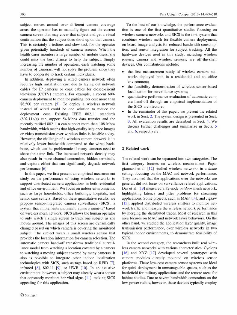
Figure 1 shows the map of the deployment, with the
server marked as ‘‘S’’. Since the house is relatively small
and every node can reach the server directly, the 10 nodes
form an one-hop star network topology.
For the office testbed, we deployed 15 wireless nodes on
the second and third floor of a six-story concrete structure
building. The building is covered by the university’s
WLAN access points (APs), which use both 802.11g and
802.11a. Besides these APs, there are microwave ovens,
wireless sensors, and Bluetooth devices that may poten-
tially interfere with the wireless transmissions in our test-
bed. We expect that such a ‘‘chaotic’’ wireless environment
will be typical for a real-world deployment, given
increased popularity of home APs, wireless sensors, and
community meshes [22].
In this testbed, each wireless node is a RouterBOARD
532A device, which has MIPS 400 MHz CPU, 64 MB
RAM, and 2 GB Compact-Flash disk. Each node can have
one or two Mini PCI wireless radio cards, for which we
used Wistron Neweb CM9 with Atheros AR5213A chipset.
On all wireless nodes, we used omni-directional antennas
that have 3 and 5 dbi gains on 2.4 and 5 GHz frequencies,
respectively. Each node installed OpenWrt Kamikaze 7.09
with Linux kernel 2.6.21-5 and MadWifi 0.9.4 (r2568-
20070710 svn snapshot). The server is same as the one
used in the home testbed.
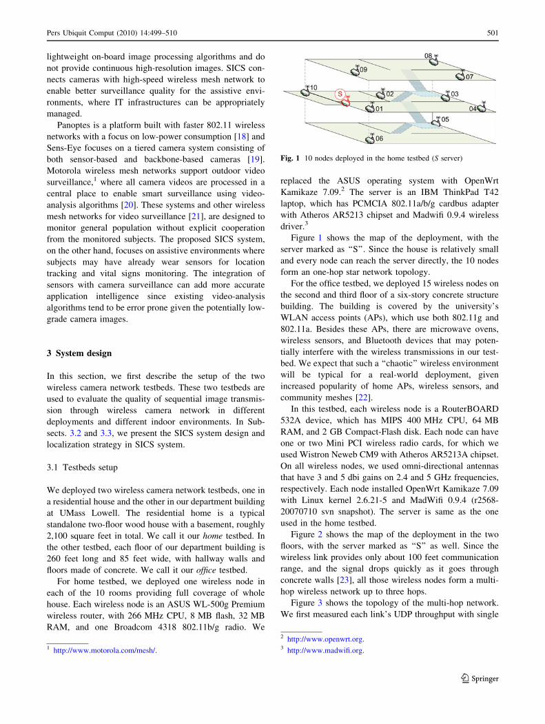
Figure 2 shows the map of the deployment in the two
floors, with the server marked as ‘‘S’’ as well. Since the
wireless link provides only about 100 feet communication
range, and the signal drops quickly as it goes through
concrete walls [23], all those wireless nodes form a multi-
hop wireless network up to three hops.
Figure 3 shows the topology of the multi-hop network.
We first measured each link’s UDP throughput with single
Fig. 1 10 nodes deployed in the home testbed (S server)
1 http://www.motorola.com/mesh/.
2 http://www.openwrt.org.3 http://www.madwifi.org.
Pers Ubiquit Comput (2010) 14:499–510 501
123
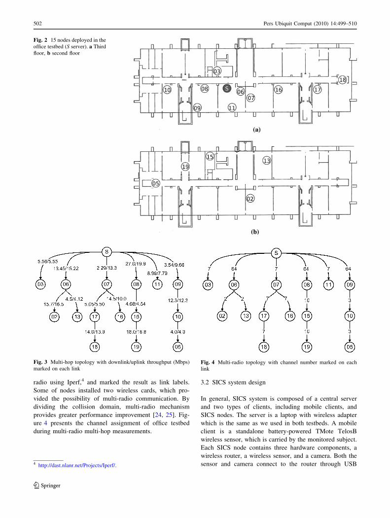
radio using Iperf,4 and marked the result as link labels.
Some of nodes installed two wireless cards, which pro-
vided the possibility of multi-radio communication. By
dividing the collision domain, multi-radio mechanism
provides greater performance improvement [24, 25]. Fig-
ure 4 presents the channel assignment of office testbed
during multi-radio multi-hop measurements.
3.2 SICS system design
In general, SICS system is composed of a central server
and two types of clients, including mobile clients, and
SICS nodes. The server is a laptop with wireless adapter
which is the same as we used in both testbeds. A mobile
client is a standalone battery-powered TMote TelosB
wireless sensor, which is carried by the monitored subject.
Each SICS node contains three hardware components, a
wireless router, a wireless sensor, and a camera. Both the
sensor and camera connect to the router through USB
Fig. 2 15 nodes deployed in the
office testbed (S server). a Third
floor, b second floor
Fig. 3 Multi-hop topology with downlink/uplink throughput (Mbps)
marked on each linkFig. 4 Multi-radio topology with channel number marked on each
link
4 http://dast.nlanr.net/Projects/Iperf/.
502 Pers Ubiquit Comput (2010) 14:499–510
123

interfaces. The wireless routers form the network back-
bone, which transmits not only the camera images back to
server but also camera control and sensor location mes-
sages between server and each node. These SICS routers
are strategically deployed with persistent power and typi-
cally do not move. The wireless sensors are the same as
mobile client and the cameras are Phillips QuickCam
Zoom, which can be assessed through the PWC Linux
driver. The wireless routers are the same as the router used
in the home testbed, since it provides native USB inter-
faces. The system architecture is shown in Fig. 5.
Figure 5 shows the SICS node architecture. When SICS
node starts up, the wireless sensor periodically receive the
localization messages from mobile client and passes them
to wireless router by USB interface. The SerialForwarder is
a process for transmitting the messages to server via
wireless mesh network. The MoteTrack process, running
on server, calculates the mobile client’s location based on
the pre-stored knowledge of network deployment and
decides which camera is covering the subject. Once the
decision is made, the control message is sent back to
camera control process in the selected wireless router, and
trigger the motion detection process5 that retrieves the
images from web camera via USB and transmits the images
back to server for display. By applying on-board motion
detection, the router does not transmit images unless there
is target movement detected to save the wireless band-
width. All wireless backbone installed OLSRD6 for auto-
matic mesh routing.
We deployed eight SICS nodes in third floor of our
department building to demonstrate the feasibility of SICS.
All the nodes were deployed in the hallway, and the camera
coverage overlapped.
3.3 Sensor-based localization
To select an appropriate camera that covers a moving
subject, we need to determine the current location of the
subject with reasonable accuracy and relatively short delay.
If the localization algorithm lacks accuracy, we may end up
selecting the wrong camera. If it takes a long time to obtain
the localization result, the subject may have already moved
to another place before we switch the camera.
It is a challenging task to use radio signals for indoor
localization because of the irregular RF propagation caused
by plenty of absorbing, scattering, and multi-path effects. It
is thus difficult to derive a simple correlation function
between the distance and the radio signal strength.
Many existing solutions require a manual process to
build a RF map to achieve meter-level localization accu-
racy [26, 27]. Namely, it is necessary to measure the RF
signatures that are signal strength samples from strategi-
cally deployed stationary beacons. While this approach
could be labor-intensive for a large facility, the RF data-
base is only needed to be built once and the room-level
localization accuracy is suitable for the purpose of SICS
applications.
We use MoteTrack [28] to build the RF signature data-
base. All sensors attached with SICS node broadcast beacon
messages and mobile client receives beacons. Different than
the original MoteTrack, which requires the mobile sensor
be attached to a laptop that stores RF database, we want the
subject to carry only a sensor, rather than a heavyweight
laptop, for the targeted assistive environment applications.
We modified the MoteTrack so the mobile client sends its
RF signature to a nearby SICS node with the strongest
signal strength. That node will then forward the RF signa-
ture to the central server for location determination.
MoteTrack increases the localization accuracy by
broadcasting the beacon messages on a set of frequency
channels C with a set of transmission power levels P. The
beacon is transmitted on all (ci, pj) combinations, for every
ci [ C and pj [ P. The beacon messages contain the
identifier, the frequency channel ci, and the power level pj.
The rational behind using more frequencies and power
levels is to increase ‘‘uniqueness’’ of the RF signatures,
since RF signals tend to have different propagation char-
acteristics on different frequency channels and have dif-
ferent propagation distances with different transmission
power levels.
Although increasing the number of transmission fre-
quency and power levels can improve the localization
Fig. 5 SICS node architecture
5 http://motion.sourceforge.net.6 http://www.olsr.org.
Pers Ubiquit Comput (2010) 14:499–510 503
123

accuracy, mobile client needs to wait enough time to
receive all beacon messages at all power levels P and then
iterate through all frequency channels C. Thus it may take a
while for the mobile sensor to compute a RF signature
before it sends it to the server for location determination. If
this delay is too long, the calculated location may be
irrelevant since the subject may have moved, leading to
incorrect camera selection. We evaluate the trade-off
between the size of C, P and the localization accuracy in
Sect. 4.2.
4 Evaluation
4.1 Transmission quality
In this subsection, we describe the measurement results of
image transmission over wireless camera networks. Since
we are interested in the quality of image transmission over
wireless networks, we measured the Peak Signal-to-Noise
Ratio (PSNR) in both home and office testbeds and delays
in the office testbed.
Although PSNR is neither the only nor the best metric
for image (or video) applications, it does give us an
objective measurement to compare the application perfor-
mance of different network configurations. It is defined via
the mean squared error (MSE) for two m 9 n monochrome
images I and K, which could be the original image and
received image in our experiment:
MSE ¼ 1
mn
Xm�1
i¼0
Xn�1
j¼0
jjIði; jÞ � Kði; jÞjj2 ð1Þ
The PSNR is defined as:
PSNR ¼ 10� log10
MAX2I
MSE
� �¼ 20� log10
MAXIffiffiffiffiffiffiffiffiffiffiMSEp� �
ð2Þ
Here, MAXI is the maximum possible pixel value of the
image. Typical values for the PSNR in lossy image
compression are between 30 and 50 dB, where higher
value represents better quality [29]. In our calculations, we
assigned PSNR to be 100 dB for two identical images
(where MSE is 0.).
From Eq. 1, we need to compare the received image
with the original image to calculate the PSNR, which
means that it is not appropriate to transmit the real-time
images directly captured from external cameras while
measuring the transmission quality. We used a webcam to
take snapshots (one per second) for over 100 s in our
laboratory. Each image’s resolution is 640 9 480 pixels,
and the size in JPEG format is about 42 K bytes. These
images were saved both on the server and the wireless
nodes. During the experiments, every node sequentially
read these images, segmented them by a given packet size
limit (experiment parameter) and sent them according to a
given speed (such as one image per second) through UDP.
On the server side, the receiver reassembled the image
files, recorded packet loss, and calculated PSNR by com-
paring the received images with the stored images.
We chose to use UDP for image transport, since TCP is
known to have bad performance over wireless links, par-
ticularly over multi-hop wireless networks [13]. Because
UDP does not guarantee reliable delivery, the packet loss
would result in lower PSNR.
4.1.1 Home testbed
In this experiment, we activated all 10 nodes to continu-
ously transmit one image per second simultaneously in
802.11g mode. The total workload (42 KB 9 8 bits/
B 9 10nodes = 3.28 Mbps) is much smaller than the wire-
less link capacity (54 Mbps for 802.11g).
As mentioned above, each images size is about 42 KB,
and the wireless packet size is up to 1,500 B. Thus each
image would be segmented into multiple packets to trans-
mit. We varied the UDP packet length as 450, 950, and
1,450 bytes to quantify the impact of packet length over
network and application-level performance.
Figure 6a shows the average and standard deviation of
the packet length impact on image PSNR. The results show
that the image quality had improved with larger packet
length for those nodes with lower throughput, such as
nodes H2, H3, H4, H6, H7, H8, and H10 (we use Hi for
labeled nodes in the home testbed). The packet length does
not impact the relatively better transmission quality nodes,
such as nodes H1, H5, and H9.
We chose the long packet length, 1,450 bytes, to com-
pare the image quality with and without the (Request to
Send/Clear to Send) RTS/CTS mechanism. 802.11 MAC
uses RTS/CTS to reduce packet collisions caused by the
hidden terminal problem [30]. Figure 6b shows the average
and standard deviation of images PSNR with and without
the RTS/CTS mechanism. The results show that RTS
mechanism improves the PSNR more than 50% in most
nodes. Every node achieves at least 95 dB PSNR, which
means that the image transmission quality is nearly perfect.
4.1.2 Office testbed
In the office testbed, we first study the one hop nodes
transmission performance to provide a comparable result
with the home testbed. The one hop nodes (see Fig. 3),
including O3, O6, O7, O8, O9, and O11 (we use Oi for
labeled nodes in the office testbed), form a star wireless
network. We started the six nodes to transmit two images
504 Pers Ubiquit Comput (2010) 14:499–510
123

per second in order to make the overall network workload
close to the home testbed experiment.
Figure 7 shows the PSNR results in different packet
lengths and with/without RTS/CTS. Comparing with
Fig. 6, all nodes achieved good and similar performance,
except for O3. The RTS/CTS mechanism even degraded
the performance for O3. We noted that the wireless link
between O3 and the server was relatively bad, and turning
on RTS/CTS added additional traffic overhead that led to
reduced quality. From Fig. 3, the throughput from O3 to the
server is only 1/4 of the best uplink throughput between O8
and the server.
From these comparison results, we can conclude that the
choice of packet length and the benefits of RTS/CTS
depend on the different wireless environment, and we need
automatic tools to determine the packet length and RTS/
CTS mechanism by measuring and monitoring link quality.
We also evaluated the performance of the multi-hop
network in the office testbed where the topology is descri-
bed in Subsect. 3.1. We activated all nodes to transmit one
image per second with packet length 1450 bytes and RTS/
CTS disabled. We found that some of nodes, which were
more than one hops to the server, achieved relatively bad
performance. Since the RouterBOARD 532A provides
multiple Mini-PCI interfaces, it is feasible to study the
multi-radio performance in wireless mesh network. We
installed up to two wireless radio cards in wireless nodes,
and configured the transmission channel as shown in Fig. 4
where the channel number is marked as label.
Figure 8 shows the multi-hop wireless network mea-
surement results. For each node, the left bars are single
radio image transmission PSNR and the right bars are
multi-radio result. The first six nodes on x axis are the
direct neighbors of the server, the next 6 nodes are the two-
hop nodes, and the last three nodes are three-hop away
from the server (see Fig. 3). All one-hop nodes’ perfor-
mance was much better than others, and some of the two-
hop nodes, such as O16 and O17, had better performance
than three-hop nodes. All three-hop nodes had unaccept-
able performance with a single radio. The performance
unfairness existed even as the channel bandwidth is much
larger than the total workload generated, which is due to
self-interference in a dense network as all radios transmit
over the same frequency at the same time [31]. Adding
additional radios and assign them with different channels
can separate collision domains and improve the wireless
mesh network performance [32]. By comparison of the two
bars for each node, we observed significant PSNR
0
20
40
60
80
100
120
140
1 2 3 4 5 6 7 8 9 10 Ave
rage
and
Std
_Dev
iatio
n of
PSN
R (
dB)
Index of Node
Std_Deviation 450 Bytes Average 450 Bytes
Std_Deviation 950 Bytes Average 950 Bytes
Std_Deviation 1450 Bytes Average 1450 Bytes
(a)
0
20
40
60
80
100
120
140
160
1 2 3 4 5 6 7 8 9 10
Ave
rage
and
Std
-Dev
of
PSN
R (
dB)
Index of Node
Std-Dev without RTS/CTSAverage without RTS/CTS
Std-Dev with RTS/CTSAverage with RTS/CTS
(b)
Fig. 6 Home testbed image transmission quality. a Packet length
impact, b RTS/CTS impact
0
20
40
60
80
100
120
140
160
180
3 6 7 8 9 11 Ave
rage
and
Std
_Dev
iatio
n of
PSN
R (
dB)
Index of Node
Std_Deviation 450 UDP length Average 450 UDP length
Std_Deviation 950 UDP length Average 950 UDP length
Std_Deviation 1450 UDP length Average 1450 UDP length
(a)
0
20
40
60
80
100
120
140
3 6 7 8 9 11
Ave
rage
and
Std
-Dev
of
PSN
R (
dB)
Index of Node
Std-Dev without RTS/CTSAverage without RTS/CTS
Std-Dev with RTS/CTSAverage with RTS/CTS
(b)
Fig. 7 Office testbed one hop nodes image transmission quality. aPacket length impact, b RTS/CTS impact
Pers Ubiquit Comput (2010) 14:499–510 505
123
improvement (about 50%) by using multiple radios, except
for O9, O13, and O17. Because the node O9 has good
wireless link to the server, it achieved good PSNR either
with single radio or multiple radios. We also measured the
network throughput of node O13 and O17, and found that
the improvements of throughput were 6 times and about
35%, respectively by using multiple radios. Since the
relationship between PSNR and throughput is not linear,
one fragment loss could cause the serious image distortion,
thus the throughput improvement does not guarantee pro-
portional PSRN improvement. All wireless nodes, except
O13, O17, and O18, achieved more than 40 dB average
PSNR with multi-radio configuration, which lead to
acceptable image quality [29].
To study the PSNR distribution, we also calculated the
cumulative distribution function (CDF) of image trans-
mission PSNR. Figure 9 shows two typical results from
two-hop node O2 and three-hop node O19, respectively. All
other nodes’ results are similar except that the proportion
of 100 dB PSNR depends on node transmission quality. We
noticed that most of broken images’ PSNR fall in the range
of 9–15 dB. Images with this quality are not useful for a
surveillance system. Because of the compressive JPEG
coding, small packet loss can cause large image PSNR
dropping. This motives a possible improvement technique.
Once the transmitting node finds that too many packets are
lost in the same image, it should stop sending additional
packets belongs to this image since the image is unable to
recover with reasonable quality. This mechanism could
improve the system performance by avoiding unnecessary
traffic.
Besides the image quality, the other important metric is
transmission delay in surveillance system. In wireless
networks, especially those using multi-hop topologies,
there are several reasons causing increased packet trans-
mission delay, such as MAC-layer back-off, frame
retransmission, and node congestion. We deployed three
wireless network sniffers near the nodes, O9, O10, and O5,
respectively. All those sniffers can log every packet sent
and received by wireless nodes with time-stamp marked.
As Fig. 3 shows, the three nodes form a three-hop wireless
path. By merging all traces collected from different snif-
fers, we can calculate each packet transmission delay as it
passes through multiple nodes.
We calculated the average end-to-end packet delay,
which is the difference between the time when packet
departs from the sender and the time when the packet
arrives to the server. We also calculated the image delay,
which is the difference between the time when the first
packet of an image departs and the time when the last
packet of that image arrives at the server, because one
image could be segmented into multiple packets. The
results are shown in Table 1.
We found that the multi-hop nodes suffered more that 10
times longer packet delay than the one-hop node both in
single radio and multiple radios configurations. The reason
is that the packet from a multi-hop node, needs more times
to compete for wireless media. For example, the packets
sent from O5 need to contend for wireless channel access
three times, each time it may need to back off or retransmit.
The multi-radio mechanism did help all nodes to reduce the
packet delay because of the reduced interference.
Figure 10 shows the CDF of image transmission delay
in single radio and multiple radios configurations. We
found that the CDF in multiple radios are steeper than
single radio, which means that the multiple radio mecha-
nism helps the image transmission more smoothly. The
packets sent from three hops nodes in single radio network
suffered two obviously different delay ranges, about 40%
images delay 0.2–0.9 s and another 40% images delay 5–
20 s. By checking the image transmission traces, we also
found the long image delay usually happened continuously.
This burst delay could seriously degrade the video sur-
veillance system’s performance. For example, this delay
could cause monitoring operator to miss the important
events. By using multiple radios, the delay distributions are
much evener than the single radio network, all delays
collapse into a smaller range.
4.2 Localization quality
We selected the distance errors in meters as a metric to
evaluate the quality of localization, which is the difference
between the actual location and the estimated location. For
each measurement, we placed the mobile client at multiple
different positions and let the system estimate the client’s
positions. The average estimate errors are considered as the
measurement results.
We first calculated the distance errors against a varying
number of transmission power levels. We also made sure
that the mobile sensor could hear from at least 6 beacon
0
20
40
60
80
100
120
140
160
3 6 7 8 9 11 2 10 13 15 16 17 5 18 19Ave
rage
and
Std
_Dev
iatio
n of
PSN
R (
dB)
Index of Node
Std_Deviation Single RadioAverage Single Radio
Std_Deviation Multiple RadiosAverage Multiple Radios
Fig. 8 Office Testbed multi-hop transmission quality
506 Pers Ubiquit Comput (2010) 14:499–510
123

sensors, as suggested by Mote-Track authors [29]. Here we
fixed the frequency channel to be 1 and varied the number
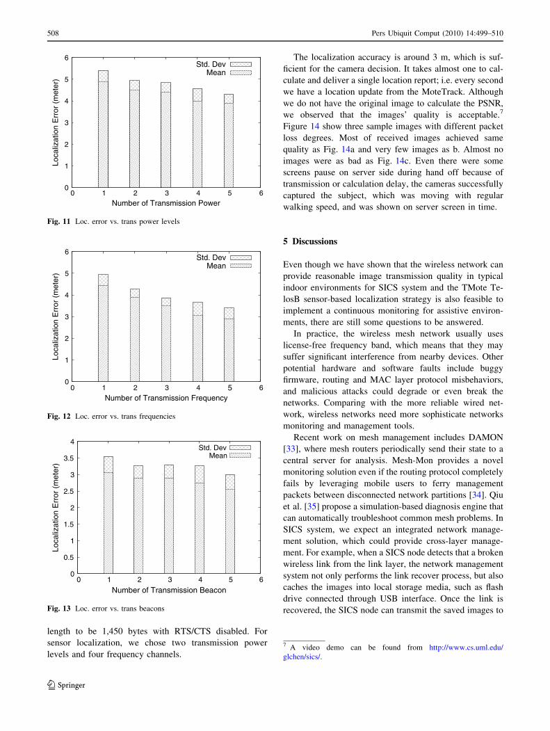
of power levels from 1 to 5.
Figure 11 shows that increasing the number of trans-
mission power levels decreases the distance errors of
localization. It is also clear that using two transmission
power levels reduces error in distance by 14% approxi-
mately, by comparing with using only a single transmission
power level. Using additional power levels, however, we
can only further reduce the error distance by 2–5%. Con-
sidering that using more power levels causes longer cal-
culation time, we chose two transmission power levels for
the SICS system, which gives us a room-level localization
accuracy and relatively shorter delay.
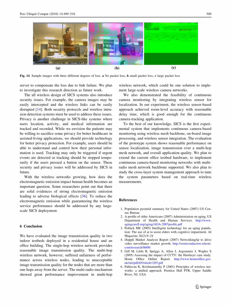
Figure 12 shows the distance errors against the number
of transmission frequencies by fixing transmission power
levels at two. From these results, we found that using 3 or 4
frequency channels could give us distance errors of less
than 4 m, which is comparable to a single camera’s typical
coverage range and thus is sufficient for automatic camera
selection. Reducing the number of frequency channels used
by the sensors will also limit the potential interference to
other channels, such as those used by SICS 802.11 mesh
network, since both 802.15.4 and 802.11 work in 2.4 GHz.
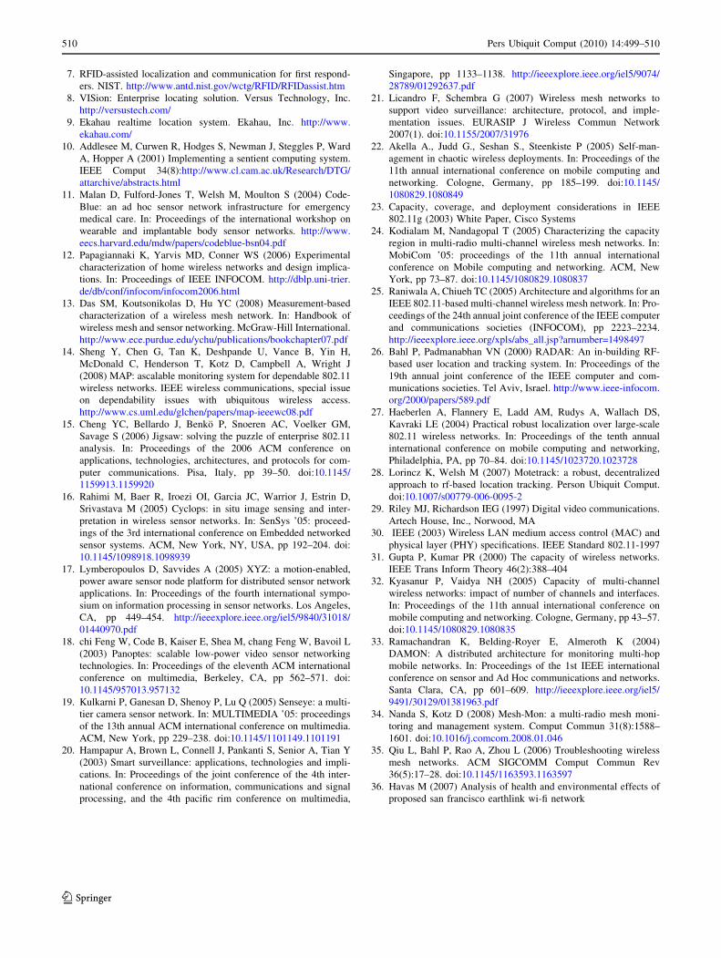
Having found the desired number of transmission power
levels and frequencies, we further evaluated the impact of
number of beacons being heard by the mobile client at any
point to the localization errors. It is important to note that
the beacons should be well spread in the space. Doing so
helps us to get varying signal strengths from beacons.
Hence, we used standalone wireless sensor powered by
batteries at the ends of a hallway in the office testbed
(Fig. 13).
Figure 13 shows that increasing number of beacons does
not improve the localization significantly. We believe that
a typical indoor camera network deployment, with one
beacon per camera, should be sufficient for sensor
localization.
4.3 Overall quality of SICS
Due to the hardware and camera driver’s restrictions, we
set each SICS node to transmit five images per second and
each image’s resolution to be 160 9 128. We chose packet
0
0.1
0.2
0.3
0.4
0.5
0.6
0.7
0.8
0.9
1
10 100
CD
FPSNR (dB)
single radio multiple radios
(a)
0
0.1
0.2
0.3
0.4
0.5
0.6
0.7
0.8
0.9
1
10 100
CD
F
PSNR (dB)
single radio multiple radios
(b)
Fig. 9 Cumulative distribution
function (CDF) of two typical
nodes’ image PSNR. a Node 2,
bNode 19
Table 1 Average transmission delay (s)
Hop Packet delay (s) Image delay (s)
Single radio Multiple radios Single radio Multiple radios
1 0.0034 0.0018 0.0382 0.0286
2 0.0396 0.1567 0.9100 0.4794
3 3.4272 0.5081 6.7805 3.0943
0
0.1
0.2
0.3
0.4
0.5
0.6
0.7
0.8
0.9
1
0.001 0.01 0.1 1 10 100
CD
F
Image delay (s)
1 hop 2 hops 3 hops
(a)
0
0.1
0.2
0.3
0.4
0.5
0.6
0.7
0.8
0.9
1
0.001 0.01 0.1 1 10 100
CD
F
Image delay (s)
1 hop 2 hops 3 hops
(b)
Fig. 10 Cumulative
distribution function (CDF) of
image transmission delay. aSingle radio delay, b Multi-
radio delay
Pers Ubiquit Comput (2010) 14:499–510 507
123
length to be 1,450 bytes with RTS/CTS disabled. For
sensor localization, we chose two transmission power
levels and four frequency channels.
The localization accuracy is around 3 m, which is suf-
ficient for the camera decision. It takes almost one to cal-
culate and deliver a single location report; i.e. every second
we have a location update from the MoteTrack. Although
we do not have the original image to calculate the PSNR,
we observed that the images’ quality is acceptable.7
Figure 14 show three sample images with different packet
loss degrees. Most of received images achieved same
quality as Fig. 14a and very few images as b. Almost no
images were as bad as Fig. 14c. Even there were some
screens pause on server side during hand off because of
transmission or calculation delay, the cameras successfully
captured the subject, which was moving with regular
walking speed, and was shown on server screen in time.
5 Discussions
Even though we have shown that the wireless network can
provide reasonable image transmission quality in typical
indoor environments for SICS system and the TMote Te-
losB sensor-based localization strategy is also feasible to
implement a continuous monitoring for assistive environ-
ments, there are still some questions to be answered.
In practice, the wireless mesh network usually uses
license-free frequency band, which means that they may
suffer significant interference from nearby devices. Other
potential hardware and software faults include buggy
firmware, routing and MAC layer protocol misbehaviors,
and malicious attacks could degrade or even break the
networks. Comparing with the more reliable wired net-
work, wireless networks need more sophisticate networks
monitoring and management tools.
Recent work on mesh management includes DAMON
[33], where mesh routers periodically send their state to a
central server for analysis. Mesh-Mon provides a novel
monitoring solution even if the routing protocol completely
fails by leveraging mobile users to ferry management
packets between disconnected network partitions [34]. Qiu
et al. [35] propose a simulation-based diagnosis engine that
can automatically troubleshoot common mesh problems. In
SICS system, we expect an integrated network manage-
ment solution, which could provide cross-layer manage-
ment. For example, when a SICS node detects that a broken
wireless link from the link layer, the network management
system not only performs the link recover process, but also
caches the images into local storage media, such as flash
drive connected through USB interface. Once the link is
recovered, the SICS node can transmit the saved images to
0
1
2
3
4
5
6
0 1 2 3 4 5 6
Loca
lizat
ion
Err
or (
met
er)
Number of Transmission Frequency
Std. DevMean
Fig. 12 Loc. error vs. trans frequencies
0
0.5
1
1.5
2
2.5
3
3.5
4
0 1 2 3 4 5 6
Loca
lizat
ion
Err
or (
met
er)
Number of Transmission Beacon
Std. DevMean
Fig. 13 Loc. error vs. trans beacons
0
1
2
3
4
5
6
0 1 2 3 4 5 6
Loca
lizat
ion
Err
or (
met
er)
Number of Transmission Power
Std. DevMean
Fig. 11 Loc. error vs. trans power levels
7 A video demo can be found from http://www.cs.uml.edu/
glchen/sics/.
508 Pers Ubiquit Comput (2010) 14:499–510
123
server to compensate the loss due to link failure. We plan
to investigate this research direction as future work.
The all wireless design of SICS systems also introduce
security issues. For example, the camera images may be
easily intercepted and the wireless links can be easily
disrupted [14]. Both security protocols and wireless intru-
sion detection systems must be used to address these issues.
Privacy is another challenge in SICS-like systems where
users location, activity, and medical information are
tracked and recorded. While we envision the patients may
be willing to sacrifice some privacy for better healthcare in
assisted-living applications, we should provide technology
for better privacy protection. For example, users should be
able to understand and control how their personal infor-
mation is used. Tracking may only be triggered if urgent
events are detected or tracking should be stopped tempo-
rarily if the users pressed a button on the sensor. These
security and privacy issues will be addressed by SICS in
future.
With the wireless networks growing, how does the
electromagnetic emission impact human health becomes an
important question. Some researchers point out that there
are solid evidences of strong electromagnetic emission
leading to adverse biological effects [36]. To reduce the
electromagnetic emission while guaranteeing the wireless
service performance should be addressed by any large-
scale SICS deployment.
6 Conclusion
We have evaluated the image transmission quality in two
indoor testbeds deployed in a residential house and an
office building. The single-hop wireless network provides
reasonable image transmission quality. The multi-hop
wireless network, however, suffered unfairness of perfor-
mance across wireless nodes, leading to unacceptable
image transmission quality for the nodes that are more than
one hops away from the server. The multi-radio mechanism
showed great performance improvement in multi-hop
wireless network, which could be one solution to imple-
ment large-scale wireless camera networks.
We also demonstrated the feasibility of continuous
camera monitoring by integrating wireless sensor for
localization. In our experiment, the wireless sensor-based
approach achieved room-level accuracy with reasonable
delay time, which is good enough for the continuous
camera-tracking application.
To the best of our knowledge, SICS is the first experi-
mental system that implements continuous camera-based
monitoring using wireless mesh backbone, on-board image
processing, and wireless sensor integration. The evaluation
of the prototype system shows reasonable performance on
sensor localization, image transmission over a multi-hop
mesh network, and overall application quality. We plan to
extend the current office testbed hardware, to implement
continuous camera-based monitoring networks with multi-
radio mesh network backbone supported. We also plan to
study the cross-layer system management approach to tune
the system parameters based on real-time wireless
measurements.
References
1. Population pyramid summary for United States (2007) US Cen-
sus Bureau
2. A profile of older Americans (2007) Administration on aging, US
Department of Health and Human Services. http://www.
agingcarefl.org/aging/AOA-2007profile.pdf
3. Pollack ME (2005) Intelligent technology for an aging popula-
tion: The use of ai to assist elders with cognitive impairment. AI
Magazine 26(2):9–24
4. iSuppli Market Analysis Report (2007) Networking/ip to drive
video surveillance market growth. http://semiconductors.tekrati.
com/research/8608/
5. Gill M, Little R, Spriggs A, Allen J, Argomaniz J, Waples S
(2005) Assessing the impact of CCTV: the Hawkeye case study.
Home Office Online Report. http://www.homeoffice.gov.
uk/rds/pdfs05/rdsolr1205.pdf
6. Pahlavan K, Krishnamurthy P (2001) Principles of wireless net-
works: a unified approach. Prentice Hall PTR, Upper Saddle
River, NJ, USA
Fig. 14 Sample images with three different degrees of loss. a No packet loss, b small packet loss, c large packet loss
Pers Ubiquit Comput (2010) 14:499–510 509
123
7. RFID-assisted localization and communication for first respond-
ers. NIST. http://www.antd.nist.gov/wctg/RFID/RFIDassist.htm
8. VISion: Enterprise locating solution. Versus Technology, Inc.
http://versustech.com/
9. Ekahau realtime location system. Ekahau, Inc. http://www.
ekahau.com/
10. Addlesee M, Curwen R, Hodges S, Newman J, Steggles P, Ward
A, Hopper A (2001) Implementing a sentient computing system.
IEEE Comput 34(8):http://www.cl.cam.ac.uk/Research/DTG/
attarchive/abstracts.html
11. Malan D, Fulford-Jones T, Welsh M, Moulton S (2004) Code-
Blue: an ad hoc sensor network infrastructure for emergency
medical care. In: Proceedings of the international workshop on
wearable and implantable body sensor networks. http://www.
eecs.harvard.edu/mdw/papers/codeblue-bsn04.pdf
12. Papagiannaki K, Yarvis MD, Conner WS (2006) Experimental
characterization of home wireless networks and design implica-
tions. In: Proceedings of IEEE INFOCOM. http://dblp.uni-trier.
de/db/conf/infocom/infocom2006.html
13. Das SM, Koutsonikolas D, Hu YC (2008) Measurement-based
characterization of a wireless mesh network. In: Handbook of
wireless mesh and sensor networking. McGraw-Hill International.
http://www.ece.purdue.edu/ychu/publications/bookchapter07.pdf
14. Sheng Y, Chen G, Tan K, Deshpande U, Vance B, Yin H,
McDonald C, Henderson T, Kotz D, Campbell A, Wright J
(2008) MAP: ascalable monitoring system for dependable 802.11
wireless networks. IEEE wireless communications, special issue
on dependability issues with ubiquitous wireless access.
http://www.cs.uml.edu/glchen/papers/map-ieeewc08.pdf
15. Cheng YC, Bellardo J, Benko P, Snoeren AC, Voelker GM,
Savage S (2006) Jigsaw: solving the puzzle of enterprise 802.11
analysis. In: Proceedings of the 2006 ACM conference on
applications, technologies, architectures, and protocols for com-
puter communications. Pisa, Italy, pp 39–50. doi:10.1145/
1159913.1159920
16. Rahimi M, Baer R, Iroezi OI, Garcia JC, Warrior J, Estrin D,
Srivastava M (2005) Cyclops: in situ image sensing and inter-
pretation in wireless sensor networks. In: SenSys ’05: proceed-
ings of the 3rd international conference on Embedded networked
sensor systems. ACM, New York, NY, USA, pp 192–204. doi:
10.1145/1098918.1098939
17. Lymberopoulos D, Savvides A (2005) XYZ: a motion-enabled,
power aware sensor node platform for distributed sensor network
applications. In: Proceedings of the fourth international sympo-
sium on information processing in sensor networks. Los Angeles,
CA, pp 449–454. http://ieeexplore.ieee.org/iel5/9840/31018/
01440970.pdf
18. chi Feng W, Code B, Kaiser E, Shea M, chang Feng W, Bavoil L
(2003) Panoptes: scalable low-power video sensor networking
technologies. In: Proceedings of the eleventh ACM international
conference on multimedia, Berkeley, CA, pp 562–571. doi:
10.1145/957013.957132
19. Kulkarni P, Ganesan D, Shenoy P, Lu Q (2005) Senseye: a multi-
tier camera sensor network. In: MULTIMEDIA ’05: proceedings
of the 13th annual ACM international conference on multimedia.
ACM, New York, pp 229–238. doi:10.1145/1101149.1101191
20. Hampapur A, Brown L, Connell J, Pankanti S, Senior A, Tian Y
(2003) Smart surveillance: applications, technologies and impli-
cations. In: Proceedings of the joint conference of the 4th inter-
national conference on information, communications and signal
processing, and the 4th pacific rim conference on multimedia,
Singapore, pp 1133–1138. http://ieeexplore.ieee.org/iel5/9074/
28789/01292637.pdf
21. Licandro F, Schembra G (2007) Wireless mesh networks to
support video surveillance: architecture, protocol, and imple-
mentation issues. EURASIP J Wireless Commun Network
2007(1). doi:10.1155/2007/31976
22. Akella A., Judd G., Seshan S., Steenkiste P (2005) Self-man-
agement in chaotic wireless deployments. In: Proceedings of the
11th annual international conference on mobile computing and
networking. Cologne, Germany, pp 185–199. doi:10.1145/
1080829.1080849
23. Capacity, coverage, and deployment considerations in IEEE
802.11g (2003) White Paper, Cisco Systems
24. Kodialam M, Nandagopal T (2005) Characterizing the capacity
region in multi-radio multi-channel wireless mesh networks. In:
MobiCom ’05: proceedings of the 11th annual international
conference on Mobile computing and networking. ACM, New
York, pp 73–87. doi:10.1145/1080829.1080837
25. Raniwala A, Chiueh TC (2005) Architecture and algorithms for an
IEEE 802.11-based multi-channel wireless mesh network. In: Pro-
ceedings of the 24th annual joint conference of the IEEE computer
and communications societies (INFOCOM), pp 2223–2234.
http://ieeexplore.ieee.org/xpls/abs_all.jsp?arnumber=1498497
26. Bahl P, Padmanabhan VN (2000) RADAR: An in-building RF-
based user location and tracking system. In: Proceedings of the
19th annual joint conference of the IEEE computer and com-
munications societies. Tel Aviv, Israel. http://www.ieee-infocom.
org/2000/papers/589.pdf
27. Haeberlen A, Flannery E, Ladd AM, Rudys A, Wallach DS,
Kavraki LE (2004) Practical robust localization over large-scale
802.11 wireless networks. In: Proceedings of the tenth annual
international conference on mobile computing and networking,
Philadelphia, PA, pp 70–84. doi:10.1145/1023720.1023728
28. Lorincz K, Welsh M (2007) Motetrack: a robust, decentralized
approach to rf-based location tracking. Person Ubiquit Comput.
doi:10.1007/s00779-006-0095-2
29. Riley MJ, Richardson IEG (1997) Digital video communications.
Artech House, Inc., Norwood, MA
30. IEEE (2003) Wireless LAN medium access control (MAC) and
physical layer (PHY) specifications. IEEE Standard 802.11-1997
31. Gupta P, Kumar PR (2000) The capacity of wireless networks.
IEEE Trans Inform Theory 46(2):388–40432. Kyasanur P, Vaidya NH (2005) Capacity of multi-channel
wireless networks: impact of number of channels and interfaces.
In: Proceedings of the 11th annual international conference on
mobile computing and networking. Cologne, Germany, pp 43–57.
doi:10.1145/1080829.1080835
33. Ramachandran K, Belding-Royer E, Almeroth K (2004)
DAMON: A distributed architecture for monitoring multi-hop
mobile networks. In: Proceedings of the 1st IEEE international
conference on sensor and Ad Hoc communications and networks.
Santa Clara, CA, pp 601–609. http://ieeexplore.ieee.org/iel5/
9491/30129/01381963.pdf
34. Nanda S, Kotz D (2008) Mesh-Mon: a multi-radio mesh moni-
toring and management system. Comput Commun 31(8):1588–
1601. doi:10.1016/j.comcom.2008.01.046
35. Qiu L, Bahl P, Rao A, Zhou L (2006) Troubleshooting wireless
mesh networks. ACM SIGCOMM Comput Commun Rev
36(5):17–28. doi:10.1145/1163593.1163597
36. Havas M (2007) Analysis of health and environmental effects of
proposed san francisco earthlink wi-fi network
510 Pers Ubiquit Comput (2010) 14:499–510
123