design by subdivision
TRANSCRIPT
Design by Subdivision
Michael Hansmeyer
Department for CAAD - Institute for Technology in Architecture Swiss Federal Institute of Technology (ETH)
Schafmattstr. 32, CH-8093, Zurich, Switzerland [email protected]
Abstract
This paper examines the role that a modified Catmull-Clark subdivision process can have in the generation of complex geometrical forms. In a first step, this paper presents modifications to the subdivision process’ weighting schemes. In a second step, this paper outlines strategies for a spatial specification of these weights using both intrinsic attributes of the mesh and external parameters. Finally, the paper presents forms generated with this modified process and method.
Introduction Subdivision processes have traditionally been used in computer graphics to generate smooth surfaces from a coarser polygonal mesh. They are currently used extensively in 3D modeling and in character animation. This paper focuses on the Catmull-Clark [1][2] process and explores to what extent it can be used more generally as design tool to generate complex geometrical form. In the first part of the paper, the process’ weighting scheme is parameterized to allow for a variable interpolation of vertices. In addition, vertex extrusion parameters are incorporated. The second part of the paper explores strategies for a differentiated spatial specification of weights. On the one hand, intrinsic attributes of the mesh such as its topology are considered. On the other hand the use of external environmental weights is outlined. The appendix presents forms that have been generated using this approach.
Parameterization of the Weighting Rules
Subdivision Explained. Subdivision processes take as an input a polygonal mesh. They recursively apply a subdivision scheme to this mesh to produce a denser, generally smoother, output mesh. Subdivision schemes can be understood by considering two parts: topological rules and weighting rules. The topological rules specify how to obtain the combinatorics of the refined mesh from the combinatorics of the input mesh by generating new vertices, edges and faces. The weighting rules specify how to calculate the positions of these new vertices based on interpolation between vertices of the input mesh.
The Catmull-Clark process generates smooth and rounded forms when using the prescribed weighting rules. By introducing parameters to allow for variations in these weighting rules, non-rounded forms with highly diverse attributes can be produced. These parameters are henceforth referred to as weights. Using a simple hexahedron as an input mesh can yield forms with features as diverse as concavity and convexity, the appearance of branching, porosity, and fractalization – just to name a few. Traditionally the scheme’s weighting rules calculate the position of new vertices strictly as an interpolation of previous-generation vertices. These rules are amended to allow the extrusion of vertices along face, edge and vertex normals. This extended scheme is described below.
Bridges 2010: Mathematics, Music, Art, Architecture, Culture
167
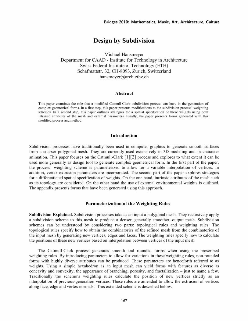
Extended Catmull-Clark Scheme. The Catmull-Clark process generates k new quadrilateral faces for each face in the input mesh, where k is the number of vertices of the face. The following is a step-by-step explanation of the process using the example of a hexahedron as an input mesh:
Figure 1: Subdivided Catmull-Clark hexahedron: input mesh and first iteration mesh
1. For each face, generate a new face point that is an average of the face’s vertices. This point can be extruded along the face’s normal vector nf using weight wf.
!
" F 1
= (P1
+ P2
+ P3
+ P4) /4 +
! n f # w f
. (1)
2. For each edge, generate an edge midpoint that is a weighted interpolation of the new face points adjacent to the edge with the edge’s endpoints. This edge midpoint can be extruded along the edge’s normal vector ne (defined as an average of the normal vectors of the attached faces) using weight we.
!
" E 1
= ((F1+ F
2)(1+ w
1) + (P
1+ P
4)(1# w
1)) /4 +
! n
e$ w
e. (2)
3. For each initial vertex of the mesh, generate a new vertex point that is a weighted interpolation of the average F of all i face points touching the vertex with the average E of all edge midpoints for edges touching the vertex. The original vertex P factors into the equation when i exceeds 3. This new vertex can be extruded along the previous vertex’s normal vector np using weight wp.
!
" V 1
= (F(1+ w2) + 2E(1# w
2/2) + (i # 3)P
1) /i +
! n p $ wp
. (3)
4. Each new face point is connected to the new edge points of edges that made up the original face. Each new vertex point is connected to the new edge points of the original edges incident on the original vertex.
Each of the extrusion vectors in the formulas above is scaled by the dimensions of the incident faces. After one iteration of this subdivision algorithm, vertices produced can be distinguished as deriving from face midpoints, edge midpoints, or previous vertices. Thus additional weights can be added to equation (1) to control the placement of subsequent midpoints:
!
" " F 1
= (( " V 1(1+ w
3) + " F
1(1# w
3))(1+ w
4) + ( " E
1+ " E
2)(1# w
4)) /4 +
! n f $ w f
. (4)
Weights introduced in equations (1) to (4) can be integrated into weighting stencils:
Figure 2: Catmull-Clark stencils for face points, edge points, and vertex points with the
Introduced weights. The rightmost figure is the face point stencil for use after the first iteration.
Hansmeyer
168
Spatial Specification of Weights The previous section presented modifications to the Catmull-Clark subdivision scheme, primarily though the introduction of weighting parameters. These weighting parameter do not need to be constant for the mesh, but can be differentiated spatially. This differentiation greatly increases the scope of possible forms, and allows a high degree of control.
The concept of non-stationary weights implies that weights can assume distinct values at each iteration of the subdivision process. Non-uniform weights imply using distinct values at different parts of the input mesh within one subdivision iteration. Three approaches to specifying non-uniform weights are considered:
1. Variation based on the mesh’s intrinsic attributes 2. Variation based on extrinsic parameters 3. Variation based on tagging vertices and faces
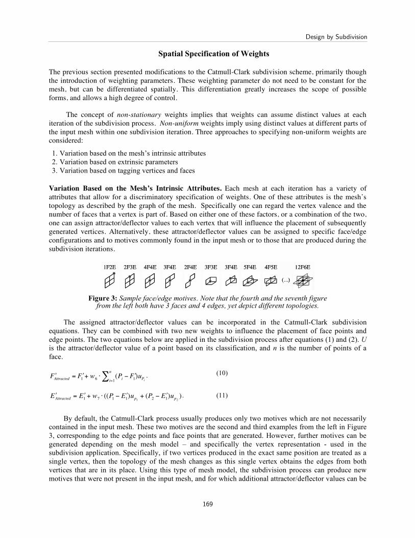
Variation Based on the Mesh’s Intrinsic Attributes. Each mesh at each iteration has a variety of attributes that allow for a discriminatory specification of weights. One of these attributes is the mesh’s topology as described by the graph of the mesh. Specifically one can regard the vertex valence and the number of faces that a vertex is part of. Based on either one of these factors, or a combination of the two, one can assign attractor/deflector values to each vertex that will influence the placement of subsequently generated vertices. Alternatively, these attractor/deflector values can be assigned to specific face/edge configurations and to motives commonly found in the input mesh or to those that are produced during the subdivision iterations.
Figure 3: Sample face/edge motives. Note that the fourth and the seventh figure
from the left both have 3 faces and 4 edges, yet depict different topologies.
The assigned attractor/deflector values can be incorporated in the Catmull-Clark subdivision equations. They can be combined with two new weights to influence the placement of face points and edge points. The two equations below are applied in the subdivision process after equations (1) and (2). U is the attractor/deflector value of a point based on its classification, and n is the number of points of a face.
!
" F Attracted
= " F 1 + w6 # (Pi$ " F 1
i=1
n
% )uP
i
. (10)
!
" E Attracted = " E 1
+ w7# ((P
1$ " E
1)up1
+ (P2$ " E
1)up2
) . (11)
By default, the Catmull-Clark process usually produces only two motives which are not necessarily contained in the input mesh. These two motives are the second and third examples from the left in Figure 3, corresponding to the edge points and face points that are generated. However, further motives can be generated depending on the mesh model – and specifically the vertex representation - used in the subdivision application. Specifically, if two vertices produced in the exact same position are treated as a single vertex, then the topology of the mesh changes as this single vertex obtains the edges from both vertices that are in its place. Using this type of mesh model, the subdivision process can produce new motives that were not present in the input mesh, and for which additional attractor/deflector values can be
Design by Subdivision
169
specified. These constellations can be intentionally invoked by specifying a minimum distance beneath which two close vertices are joined. Using these joined vertices introduces a type of non-linearity into the subdivision process: small changes in the subdivision weights can lead to seemingly abrupt changes in output as the mesh’s topology is altered.
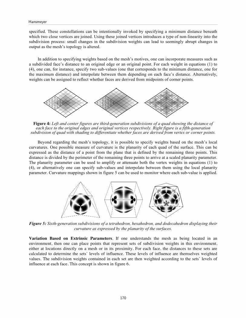
In addition to specifying weights based on the mesh’s motives, one can incorporate measures such as a subdivided face’s distance to an original edge or an original point. For each weight in equations (1) to (4), one can, for instance, specify two sub-values (one that corresponds to the minimum distance, one for the maximum distance) and interpolate between them depending on each face’s distance. Alternatively, weights can be assigned to reflect whether faces are derived from midpoints of corner points.
Figure 4: Left and center figures are third-generation subdivisions of a quad showing the distance of
each face to the original edges and original vertices respectively. Right figure is a fifth-generation subdivision of quad with shading to differentiate whether faces are derived from vertex or corner points.
Beyond regarding the mesh’s topology, it is possible to specify weights based on the mesh’s local curvatures. One possible measure of curvature is the planarity of each quad of the surface. This can be expressed as the distance of a point from the plane that is defined by the remaining three points. This distance is divided by the perimeter of the remaining three points to arrive at a scaled planarity parameter. The planarity parameter can be used to amplify or attenuate both the vertex weights in equations (1) to (4), or alternatively one can specify sub-values and interpolate between them using the local planarity parameter. Curvature mappings shown in figure 5 can be used to monitor where each sub-value is applied.
Figure 5: Sixth-generation subdivisions of a tetrahedron, hexahedron, and dodecahedron displaying their
curvature as expressed by the planarity of the surfaces.
Variation Based on Extrinsic Parameters. If one understands the mesh as being located in an environment, then one can place points that represent sets of subdivision weights in this environment, either at locations directly on a mesh or in its proximity. For each face, the distances to these sets are calculated to determine the sets’ levels of influence. These levels of influence are themselves weighted values. The subdivision weights contained in each set are then weighted according to the sets’ levels of influence at each face. This concept is shown in figure 6.
Hansmeyer
170
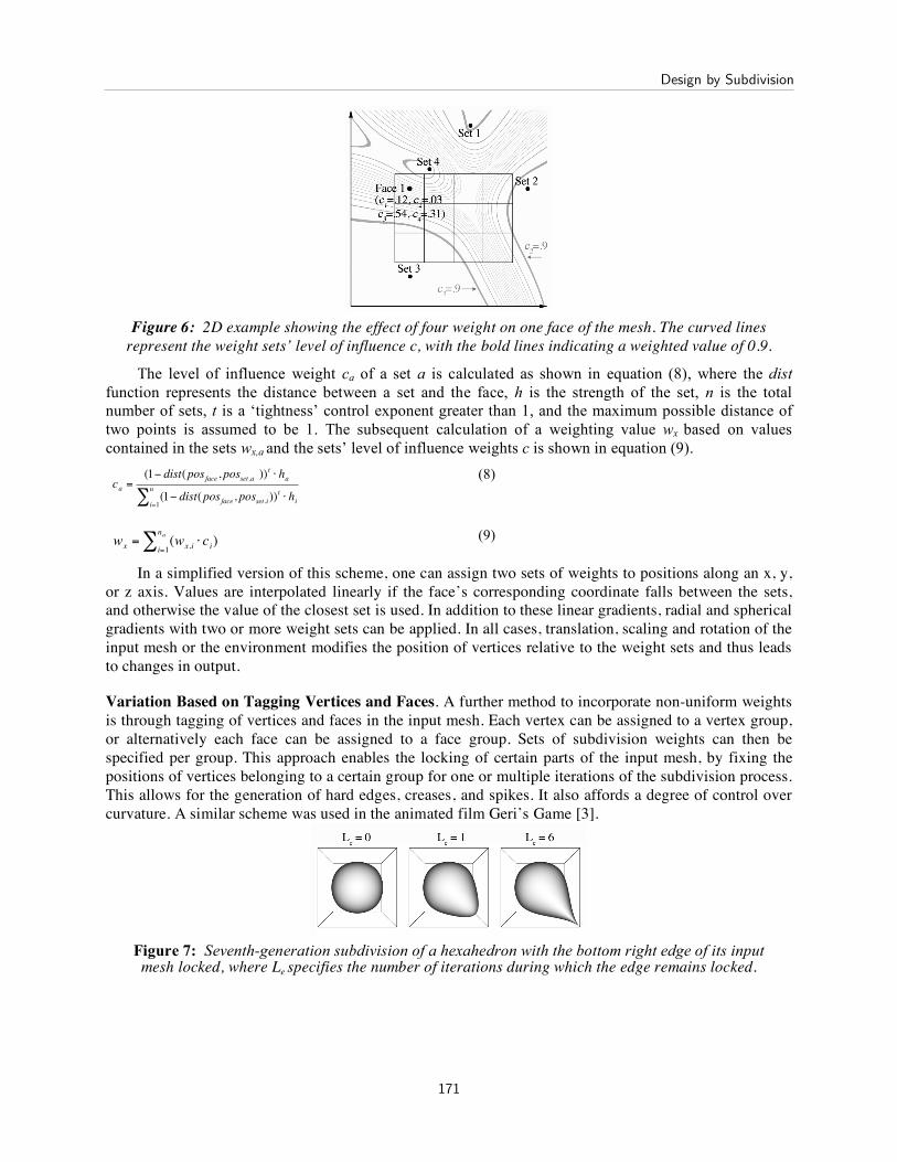
Figure 6: 2D example showing the effect of four weight on one face of the mesh. The curved lines
represent the weight sets’ level of influence c, with the bold lines indicating a weighted value of 0.9.
The level of influence weight ca of a set a is calculated as shown in equation (8), where the dist function represents the distance between a set and the face, h is the strength of the set, n is the total number of sets, t is a ‘tightness’ control exponent greater than 1, and the maximum possible distance of two points is assumed to be 1. The subsequent calculation of a weighting value wx based on values contained in the sets wx,a and the sets’ level of influence weights c is shown in equation (9).
!
ca =(1" dist(posface, posset.a ))
t # ha
(1" dist(posface, posset.i))t # hi
i=1
n
$
(8)
!
wx
= (wx,i
i=1
na
" # ci) (9)
In a simplified version of this scheme, one can assign two sets of weights to positions along an x, y, or z axis. Values are interpolated linearly if the face’s corresponding coordinate falls between the sets, and otherwise the value of the closest set is used. In addition to these linear gradients, radial and spherical gradients with two or more weight sets can be applied. In all cases, translation, scaling and rotation of the input mesh or the environment modifies the position of vertices relative to the weight sets and thus leads to changes in output.
Variation Based on Tagging Vertices and Faces. A further method to incorporate non-uniform weights is through tagging of vertices and faces in the input mesh. Each vertex can be assigned to a vertex group, or alternatively each face can be assigned to a face group. Sets of subdivision weights can then be specified per group. This approach enables the locking of certain parts of the input mesh, by fixing the positions of vertices belonging to a certain group for one or multiple iterations of the subdivision process. This allows for the generation of hard edges, creases, and spikes. It also affords a degree of control over curvature. A similar scheme was used in the animated film Geri’s Game [3].
Figure 7: Seventh-generation subdivision of a hexahedron with the bottom right edge of its input mesh locked, where Le specifies the number of iterations during which the edge remains locked.
Design by Subdivision
171
Conclusion
By adding degrees of freedom to both the subdivision weighting schemes and to how the schemes are applied, the scope of forms that can be generated increases greatly. The attached illustrations always take the simplest input meshes – the platonic solids – yet generate forms that exhibit and astounding complexity. Unlike forms generated through typical additive processes, these form are not explicable through reductionism. It is, on the contrary, often difficult to discern the source of the forms, much less the exact nature and parameters of the processes applied. It is beyond the scope of this paper to describe the correlations between individual settings and the geometric attributes these generate. Yet the processes behave mostly linearly, so that small changes in weighting values lead to gradual, traceable changes in output. Though they are not entirely predictable, the processes are deterministic and they are reproducible. Rather than simply providing a mechanism to smoothen a mesh, these expanded subdivision processes can be used as a design tool to generate an astounding enrichment of and complexity in these meshes.
References 1. E. Catmull: A Subdivision Algorithm for Computer Display of Curves Surfaces, Dissertation,
Department of Computer Science, University of Utah (1974) 2. E. Catmull and J. Clark: Recursively generated B-spline surfaces on arbitrary topological surfaces,
Computer-Aided Design 10(6):350-355 (November 1978) 3. T. DeRose, M. Kass, T. Truong, Subdivision Surfaces in Character Animation, International
Conference on Computer Graphics and Interactive Techniques, 1998
Hansmeyer
172
Illustrations
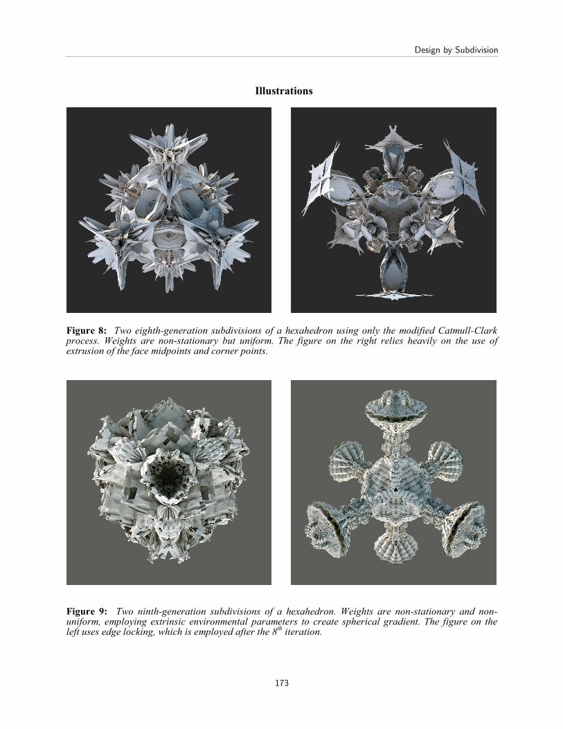
Figure 8: Two eighth-generation subdivisions of a hexahedron using only the modified Catmull-Clark process. Weights are non-stationary but uniform. The figure on the right relies heavily on the use of extrusion of the face midpoints and corner points.
Figure 9: Two ninth-generation subdivisions of a hexahedron. Weights are non-stationary and non-uniform, employing extrinsic environmental parameters to create spherical gradient. The figure on the left uses edge locking, which is employed after the 8th iteration.
Design by Subdivision
173
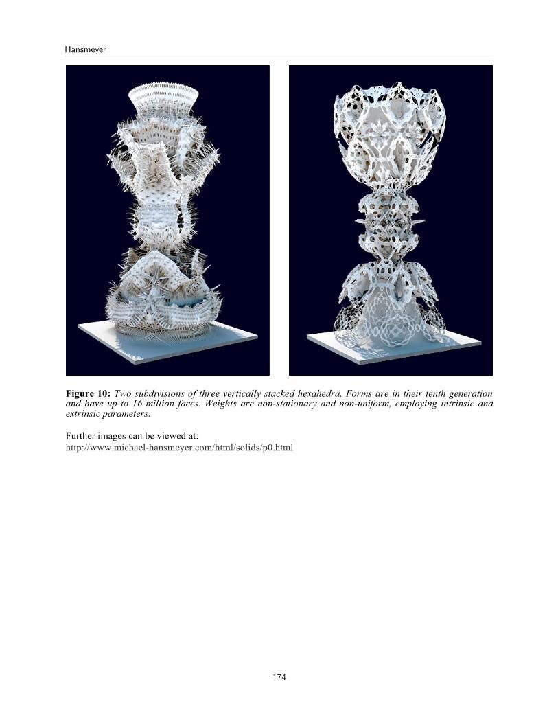
Figure 10: Two subdivisions of three vertically stacked hexahedra. Forms are in their tenth generation and have up to 16 million faces. Weights are non-stationary and non-uniform, employing intrinsic and extrinsic parameters.
Further images can be viewed at: http://www.michael-hansmeyer.com/html/solids/p0.html
Hansmeyer
174