determination of optimum speed of an internal combustion engine
TRANSCRIPT

Determination of optimum speed of an internalcombustion engine by exergy analysis
Mehmet Kopac*
Mechanical Engineering Department,Zonguldak Karaelmas University, Zonguldak 67100, TurkeyE-mail: [email protected]: [email protected]*Corresponding author
Lutfi Kokturk
Mechanical Engineering Department,Zonguldak Karaelmas University, Zonguldak, Turkey
Abstract: In this study, energy and exergy analysis are applied to theexperimental data of an internal combustion engine operating on theconventional Otto cycle. The data are collected using an engine test unitwhich enables accurate measurements of fuel flow rate, combustion air flowrate, engine load, engine speed and all the relevant temperatures. Energyand exergy efficiencies are calculated for different engine speeds andcompared. Results indicate that energy efficiency is maximum at a speed of2040 rpm whereas exergy efficiency is maximum at a speed of 2580 rpm.
Keywords: exergy analysis; exergy efficiency; internal combustion engine.
Reference to this paper should be made as follows: Kopac, M. andKokturk, L. (2005) `Determination of optimum speed of an internalcombustion engine by exergy analysis', Int. J. Exergy, Vol. 2, No. 1,pp.40±54.
Biographical notes: Mehmet Kopac received his BS degree in mechanicalengineering from the Zonguldak Engineering±Architecture State Academyin 1979 and in 1984 he received his MS degree in mechanical engineering(energy sciences) from the Istanbul Technical University, Turkey. In 1992he received his PhD degree in mechanical engineering (thermal sciences)from the Yi
�
ldi�
z Technical University of Istanbul, Turkey. At present he isan Associate Professor at the Mechanical Engineering Department ofZonguldak Karaelmas University, Turkey. His major interests are exergyanalysis of thermal systems, fluid mechanics and applications.
Biographical notes: Lutfi Kokturk received his BS degree in mechanicalengineering from the Ankara Engineering±Architecture State Academy in1977 and in 1999 he received his MS degree in mechanical engineering(energy sciences) from the Zonguldak Karaelmas University, Turkey. He iscurrently working as a Mechanical Engineer in the Directorate ofCivilisation in Barti
�
n, Turkey.
Int. J. Exergy, Vol. 2, No. 1, 200540
Copyright # 2005 Inderscience Enterprises Ltd.

1 Introduction
An exergy-based performance analysis is the performance analysis of a system basedon the second law of thermodynamics that overcomes the limit of an energy-basedanalysis. Exergy is defined as the maximum theoretical useful work obtained as asystem interacts with an equilibrium state. Exergy is generally not conserved asenergy but destroyed in the system. Exergy destruction is a measure of irreversibilitythat is the source of performance loss. Therefore, an exergy analysis assessing themagnitude of exergy destruction identifies the location, the magnitude and the sourceof thermodynamic inefficiencies in a thermal system. This provides usefulinformation to improve the overall efficiency and cost effectiveness of a systemand/or comparing the performance of the two systems.
Recent studies (Dunbar and Lior, 1994; Dunbar et al., 1992) show that almost athird of the energy of a fossil fuel is destroyed during the combustion process inpower generation. This has caused a renewed interest in exergy analyses, sinceeffective management and optimisation of thermal systems is emerging as a majormodern technical problem (Bejan et al., 1996). The equations for the second lawanalysis of a thermodynamic system are presented and discussed thoroughly(Dunbar et al., 1992) and are used to analyse the operation of power plants(Dunbar et al., 1991; Kopac, 2000; Lazzaretto and Tsatsaronis, 1999; Toffolo andLazzaretto, 2002). For internal combustion engines, early work (Flynn et al., 1984;Primus et al., 1984) on the evaluation of the global engine operation using second-law techniques was followed by detailed energy and exergy destroyed calculationsduring the diesel engine cycle (Rakopoulos et al., 1993; Rakopoulos, 1993;Rakopoulos and Kyritsis, 2001). Second-law arguments have been used toevaluate novel engine concepts (Flynn et al., 1984), to investigate the effect of theoperating parameters on efficiency (Kopac et al., 2001; Rakopoulos et al., 1993), andmore recently, to reveal interesting aspects of the transient engine operation(Rakopoulos and Giakoumis, 1997). The overall energy and exergy balance duringan engine cycle are studied analytically (Beratta and Keck, 1983; Bedran andBeratta, 1985). The exergy analysis has been used on a general system in Dincer(2000), Gogus and Ataer (1999), Gogus et al. (2002), OzdogÏ an and Arikol (1995)and Stapleton (2001).
The objective of this study is to determine the optimum speed of an Otto cycleengine using combined energy and exergy analysis.
2 Theory
A schematic control volume for an open system is shown in Figure 1. Energy,entropy and exergy balances for such a system under transient conditions are givenby Equations (1), (2) and (3).
Determination of optimum speed of an internal combustion engine 41

Figure 1 Control volume for an open system
Energy balance: Xi
_mhÿX
j
_mh�X
s
_Qÿ _W � � _Usystem �1�
Entropy balance: Xi
_msÿX
j
_ms�X
s
_Q
T� _Sgen � �_Ssystem �2�
Exergy balance:Xi
_meÿX
j
_me�X
s
_Q 1ÿ To
T
� �ÿ _Wÿ _Ed � � _Esystem
_Ed � To_Sgen
: �3�
e in Equation (3) is flow exergy per unit mass and is defined as follows:
e � etm � ech; �4�
where etm ve ech are thermomechanical and chemical exergy, respectively.Thermomechanical exergy is defined as follow (CË engel and Boles, 1998; Kotas,1985):
etm � hÿ ho ÿ To sÿ so� �; �5�
where h and s are flow enthalpy and flow entropy per unit mass at the relevanttemperature and pressure. Assuming the ideal solution assumption is valid, thespecific chemical exergy for a multicomponent stream can be calculated as follows:
�ech �Xj
i�1
yi��ech�i �6�
where yi is the mole fraction of component i in the mixture and (�ech)i is its specificchemical exergy. The definition of specific chemical exergy for each component
M. Kopac and L. Kokturk42

depends on whether the component exists in the environment. If a component existsin the environment and the environment is also an ideal solution, then
��ech�i � �RTolnyi
yei
; �7�
where yei is the mole fraction of component i in the environment. If a given
component does not exist in the environment, then its chemical exergy must becalculated by considering a chemical reaction where this component reacts with aspecies in the environment and is completely converted into species all of which alsoexist in the environment. For example, a hydrocarbon, CaHb, has the followingspecific chemical exergy;
�eCaHb� �gCaHb
� �a� b4� �gO2
ÿ a�gCO2ÿ b
2�gH2O�g�
� �� �RToln
�yeO2��a�b
4�
�yeCO2�a�ye
H2O�b=2
24 35: �8�The definition of environment adopted in this study is shown in Table 1 (Kotas,1995).
Table 1 Standard air parameters (P0� 101.325 kPa, To� 298K) (Kotas, 1995)
Component Mole fraction
N2 0.7567
O2 0.2035
CO2 0.000345
H2O 0.0303
CO 0.000007
SO2 0.000002
H2 0.0000005
Other 0.0091455
3 Experimental studies
Experiments were conducted on an existing test unit at the Mechanical EngineeringDepartment of Zonguldak Karaelmas University. The test engine was type 8601running on gasoline. A schematic diagram of the test unit is shown in Figure 2. Theexperimental set up enabled accurate measurements of fuel, combustion air, coolingwater flow rates of gas calorimeter, engine load and speed and inlet and outlettemperatures for each stream. Experimental results for different engine speedsbetween 990 and 3480 rpm are summarised in Table 2.
Determination of optimum speed of an internal combustion engine 43

Figure 2 Schematic diagram of engine test unit
Energy analysis:Fuel energy is given by:
_Qf � _mf Hu; �9�where Hu is the lower heating value and _mf is the mass flow rate of fuel, respectively.
Effective power of engine, Ne is
Ne � ! � �10�where ! and � are angular velocity and torque, respectively.
The angular velocity is related to rpm according to
! � �n
30�11�
and torque is determined by Cussons Automotive (1993).
� � 0:286L; �12�
M. Kopac and L. Kokturk44

Table 2 Experimental results
Speed,
n (rpm)
Load,
L
(N)
Torque,
�
(Nm)
Airflow
rate,
Va
(l/min)
Mass
flow
rate
offuel,
mf
(g/sec)
Mass
flow
rate
of
calorimeter
cooling
water,
mgw
(kg/h)
Tem
perature
of
surroundings,
Ta
(� C
)
Tem
perature
ofexhaust
gases,
Te1
(� C
)
Entrance
temperature
ofexh.
gasesto
the
calorimeter,
Te2
(� C
)
Exit
temperature
ofexh.
gasesfrom
the
calorimeter,
Te3
(� C
)
Exit
temperature
ofthe
coolingwater
of
calorimeter,
Tw2
(� C
)
Entrance
temperature
ofthe
coolingwater
ofcalorimeter,
Tw1
(� C
)
The
temperature
atouter
surface
ofthe
engine,
Ts
(� C
)
990
395
103
790
1.251
569
16
500
285
22
22
10
80
1530
472
135
1916
2.310
1006
16
570
370
40
30
10
80
2040
448
129
2402
2.584
1008
16
650
490
50
40
10
80
2580
413
124
2952
3.165
992
16
720
600
53
55
10
80
3000
381
113
3111
3.687
916
16
750
605
60
65
10
80
3480
336
103
2714
4.182
775
16
780
656
80
80
10
80
Determination of optimum speed of an internal combustion engine 45

where L is the measured engine load. Combining Equations (11) and (12), theeffective power of the engine can be expressed as follows:
Ne � �n
30�; �13�
then specific fuel consumption, be is
be �_mf
Ne: �14�
Total exhaust heat, _Qe
The heat content of the exhaust gas in the system can be expressed as the sum of threeconstituent parts:
1 heat loss between the exhaust manifold and the exhaust gas heat exchanger
2 heat extracted in the exhaust gas heat exchanger
3 residual heat in the gases leaving the exhaust gas heat exchanger.
The overall heat in the exhaust gases expressed as a rate of energy flow is given by:
_Qe �_mg cpg Te1 ÿ Te2� �
1� � _mg cpg Te2 ÿ Te3� �2� � _mg cpg Te3 ÿ Ta� �
3� ; �15a�
where: _mg�mass flow rate of exhaust gas; cpg� specific heat of exhaust gas;_mgw�mass flow rate of water; cpw� specific heat of water; Te1� exhaust gastemperature at engine; Te2� exhaust gas temperature at inlet to calorimeter;Te3� exhaust gas temperature at outlet from calorimeter; Tw1� cooling water inlettemperature; Tw2� cooling water outlet temperature; Ta� ambient air temperature.
Taking a heat balance of the exhaust gas calorimeter neglecting losses:
_mg cpg Te2 ÿ Te3� � � _mgw cpw Tw2 ÿ Tw1� �; �15b�
; _mg cpg �_mgw cpw Tw2 ÿ Tw1� �
Te2 ÿ Te3� � : �15c�
Substituting this expression in the overall equation:
_Qe �_mgw cp;w Tw2 ÿ Tw1� �
Te2 ÿ Te3� � Te1 ÿ Ta� �: �16�
Total heat loss (cooling water heat to radiation heat), _Qt1� ( _Qcw� _Qr)
_Qtl � _Qf ÿ Ne � _Qe
� ��17�
Energy efficiency, �I is given by:
�I �Useful output
Energy input� Ne
_Qf
: �18�
Exergy analysis:Exhaust gas exergy ( _Ee) is the sum of the thermomechanical and chemical exergy ofeach component and is calculated by Equations (4) to (8) using calculated exhaustgas compositions.
M. Kopac and L. Kokturk46

Heat exergy, _EQ
_EQ � _Q 1ÿ To
T
� �: �19�
Work exergy, _EW
_EW� _W � Ne: �20�Fuel exergy, _Ef
_Ef � _mf ech;f : �21�Exergy efficiency, �II
�II �Exergy recovered
Exergy supplied� Ne
_Es
� 1ÿ Exergy destroyed
Exergy supplied� 1ÿ
_Ed
_Es
: �22�
The supplied exergy and the recovered exergy, _Es and _ER are given by:
_Es� _Ef ; _ER� Ne � _Ee � _EQtl: �23�
4 Results and discussion
The numerical values given in Table 2 were used as input to conduct energy andexergy analysis of the engine for different speeds. The results of the energy analysisare presented in Figures 3 and 4 and Tables 3, 4 and 5. Similarly, the results of theexergy analysis are presented in Figures 5 and 6 and Tables 6 and 7.
Figure 3 Specific fuel consumption versus engine speed
Determination of optimum speed of an internal combustion engine 47

Figure 4 Effective power versus engine speed
Table 3 Effective power and specific fuel consumption versus engine speed
Speed, n(rpm)
Effective power, Ne
(kW)Specific fuel consumption, be
(g/kWh)
990 10.68 422
1530 21.63 384
2040 27.56 338
2580 33.50 340
3000 35.50 374
3480 37.50 401
Table 4 Energy balance for different speeds
Speed, n(rpm)
Fuel energy, _Qf
(kW)Effective power, Ne
(kW)Exhaust heat, _Qe
(kW)Total heat loss, _Qt1
(kW)
990 53.42 10.68 14.60 28.14
1530 98.64 21.63 39.20 37.81
2040 110.25 27.56 50.57 32.12
2580 135.15 33.51 66.70 34.94
3000 157.43 35.49 78.77 43.17
3480 178.57 37.52 83.55 57.50
M. Kopac and L. Kokturk48
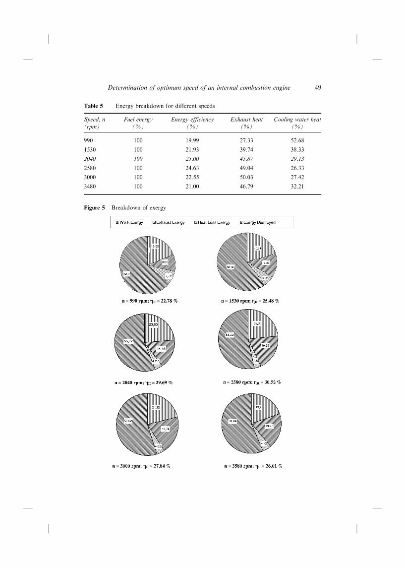
Table 5 Energy breakdown for different speeds
Speed, n(rpm)
Fuel energy(%)
Energy efficiency(%)
Exhaust heat(%)
Cooling water heat(%)
990 100 19.99 27.33 52.68
1530 100 21.93 39.74 38.33
2040 100 25.00 45.87 29.13
2580 100 24.63 49.04 26.33
3000 100 22.55 50.03 27.42
3480 100 21.00 46.79 32.21
Figure 5 Breakdown of exergy
Determination of optimum speed of an internal combustion engine 49

Figure 6 Energy efficiency, exergy efficiency and breakdown of exergy destroyed versusengine speed
Table 6 Exergy balance for different speeds
Speed,n(rpm)
Fuel exergy,_Ef
(kW)
Work exergy,Ne
(kW)
Exhaust exergy,_Ee
(kW)
Heat loss exergy,_EQ
(kW)
Exergy destroyed,_Ed
(kW)
990 56.75 10.68 5.48 4.38 36.21
1530 104.80 21.63 14.02 5.89 63.26
2040 117.14 27.56 19.30 5.00 65.28
2580 143.26 33.51 28.06 5.44 76.25
3000 167.26 35.49 33.01 6.72 92.04
3480 189.72 37.52 36.56 8.96 106.50
Table 7 Breakdown of exergy for different speeds
Speed,n(rpm)
Fuelexergy(%)
Exergyefficiency(%)
Workexergy(%)
Exhaustexergy(%)
Heat lossexergy(%)
Exergydestroyed(%)
990 100 22.78 18.82 9.66 7.72 63.80
1530 100 25.48 20.64 13.38 5.62 60.36
2040 100 29.69 23.53 16.48 4.27 55.72
2580 100 30.52 23.39 19.59 3.80 53.22
3000 100 27.84 21.22 19.74 4.02 55.02
3480 100 26.01 19.77 19.27 4.72 56.24
M. Kopac and L. Kokturk50

Analysis of Figures 3 and 4 reveals that as the effective power delivered by the engineincreases with speed, the amount of fuel consumed per unit of energy produced togoes through a minimum. For two different engine speeds, namely 2040 and2580 rpm, specific fuel consumption is almost the same (338 and 340 g/kWh). Energyefficiency is also a maximum (25.00 and 24.63%) for these speeds. In fact, energyefficiency as a function of engine speed can be deduced from specific fuelconsumption as a function of engine speed; where the former exhibits a maximum,the latter goes through a minimum. As far as the energy analysis is concerned, thereis no significant difference between 2040 and 2580 rpm as the optimum speed, but theexergy analysis clearly indicates that 2580 rpm is the optimum since it is associatedwith a higher exergy efficiency.
There are different sources of irreversibility (or destruction of exergy) associatedwith the operation of an internal combustion engine, combustion itself being a majorsource. Exergy destruction due to combustion depends on temperature, pressure andair to fuel ratio (Caton, 2000).
In this study, the ratio of the mass of air to the mass of fuel (AF) increases up toan engine speed of 2580 rpm and it decreases after this speed. The ratio of the exergydestruction or irreversibility decreases with an increase in the mass of air to the massof fuel ratio (AF) for a combustion process. Other sources of irreversibility, such asfriction and heat transfer across a temperature difference, are also expected toincrease with an increase in engine speed. The observation of a minimum in exergydestruction is due to the fact that the exergy content of the exhaust heat alsoincreases with engine speed. Hence 2580 rpm should be considered as the trueoptimum, provided that exhaust recovery devices may be employed to utilise theexergy of hot exhaust gases.
5 Conclusions
This study presents both experimental measurements and analytical modelling basedon energy and exergy analyses for an internal combustion engine operating on theconventional Otto cycle. The experimental data were collected for fuel flow rate,combustion air flow rate, engine load, engine speed and all the relevanttemperatures in an engine test unit. Energy and exergy efficiencies are calculatedfor different engine speeds and compared. Determination of the optimum enginespeed should not be based on energy analysis alone. The results of this study revealthat a combined energy and exergy analysis provides a much better and morerealistic answer.
Acknowledgements
The authors would like to acknowledge Professor Dr Mahir Arikol of BogÏ azicË iUniversity, Chemical Engineering Department, for helpful comments and usefulsuggestions.
Determination of optimum speed of an internal combustion engine 51

References
Bedran, E.C. and Beratta, G.P. (1985) `General thermodynamic analysis for enginecombustion modeling', SAE Paper No. 850205, Warrendale, PA: Society of AutomotiveEngineers Inc.
Bejan, A., Tsatsaronis, G. and Moran, M. (1996) Thermal Design and Optimization, NewYork: John Wiley and Sons Inc.
Beratta, G.P. and Keck, J.C. (1983) `Energy and entropy balances in a combustion chamber',Cumbust Sci. Technol., Vol. 30, pp.19±29.
Caton, J.A. (2000) `On the destruction of availability (exergy) due to combustion processes ±with specific application to internal-combustion engines', Energy, Vol. 25, pp.1097±1117.
CË engel, A.Y. and Boles, M.A. (1998) Thermodynamics, an Engineering Approach, McGrawHill.
Cussons Automotive Multi-Cylinder Engine Test Bed-Hydrokinetic Dynamometer (1993)P8601, p.6.
Dincer, I. (2000) `Thermodynamics, exergy and environmental impact', Energy Sources, Vol. 2,p.723.
Dunbar, W.R. and Lior, N. (1994) `Sources of combustion irreversibility', Combust Sci.Technol., Vol. 103, pp.41±61.
Dunbar, W.R., Lior, N. and Gaggioli, R.A. (1991) `Combining fuel cells with fuel-fired plantsfor improved exergy efficiency', Energy, Vol. 16, pp.1259±1274.
Dunbar, W.R., Lior, N. and Gaggioli, R.A. (1992) `The component equations of energy andexergy', Trans. ASME, J. Energy Res. Technol., Vol. 114, pp.75±83.
Flynn, P.F., Hoag, K.L., Kamel, M.N. and Primus, R.J. (1984) `A new perspective on dieselengine evaluation based on second law analysis', SAE Paper No. 840032, Warrendale, PA:Society of Automotive Engineers Inc.
Gogus, Y.A. and Ataer, O.E. (1999) `Effect of variation of environmental conditions on exergyand power conversion', in A. Bejan and E. Mamut (Eds) Thermodynamic Optimization ofComplex Energy Systems, Netherland: Kluwer; pp.231±240.
Gogus, Y.A., CË amdali, U. and Kavsaoglu, M.S. (2002) `Exergy balance of a general systemwith variation of environmental conditions and some applications', Energy, Vol. 27,pp.625±646.
Kopac, M. (2000) `Applying of energy and exergy analysis on an existing power plant', Tr. J.of Thermal Sciences and Technologies, Vol. 20, Nos. 3±4, pp.3±7.
Kopac, M., Kokturk, L. and Sahin, Y. (2001) `Principles of thermal systems optimization',13th National Thermal Sciences and Technologies Conference, Proceedings: pp.183±187.
Kotas, T.J. (1995) The Eksergy Method of Plant Analysis, Malabar, FL: Krieger PublishingCompany.
Lazzaretto, A. and Tsatsaronis, G. (1999) `On the calculation of efficiencies and cost inthermal systems', AES-Vol. 39, in Proceedings of the ASME Advanced Energy SystemsDivision.
OzdogÏ an, S. and Arikol, M. (1995) `Energy and exergy analysis of selected Turkish industries',Energy, Vol. 20, pp.73±80.
Primus, R.J., Hoag, K.L., Flynn, P.F. and Brandts, M.C. (1984) `An appraisal of advancedengine concepts using second law techniques', SAE Paper No. 841287, Warrendale, PA:Society of Automotive Engineers Inc.
Rakopoulos, C.D. (1993) `Evaluation of a spark ignition engine cycle using first and secondlaw analysis techniques', Energy Convers Mgmt., Vol. 34, pp.1299±1314.
Rakopoulos, C.D. and Giakoumis, E.G. (1997) `Simulation and exergy analysis of transientdiesel engine operation', Energy, Vol. 22, pp.875±885.
M. Kopac and L. Kokturk52

Rakopoulos, C.D. and Kyritsis, D.C. (2001) `Comparative second-law analysis of internalcombustion engine operation for methane, methanol, and dodecane fuels', Energy, Vol.26, pp.705±722.
Rakopoulos, C.D., Andritsakis, E.C. and Kyritsis, D.C. (1993) `Availability accumulation anddestruction in a DI diesel engine with special reference to the limited cooled case', HeatRecov Syst CHP, Vol. 13, pp.261±275.
Stapleton, A.J. (2001) `Exergy analysis of the UK energy system', Power and Energy, Vol. 215,p.141.
Toffolo, A. and Lazzaretto, A. (2002) `Evolutionary algorithms for multi-objective energeticand economic optimization in thermal system design', Energy, Vol. 27, pp.549±567.
Nomenclature
be Specific fuel consumption, g/kWh
cp,w Heat capacity of cooling water, kJ/kgK
e Total exergy, kJ/kg
ech Chemical exergy, kJ/kg
�ech Chemical exergy, kJ/kmol
etm Thermomechanical exergy, kJ/kg
_Ed Exergy destroyed, kW
_Ee Exhaust exergy, kW
_Ef Fuel exergy, kW
_EQ Heat exergy, kW
_Es Exergy supplied, kW
_Esystem Exergy of system, kW
_EW Work exergy, kW
�g Gibb's free energy, kJ/kmol
h Enthalpy, kJ/kg
ho Enthalpy at environmental condition, kJ/kg
Hu Lower heating value, kJ/kg
L Engine load, N
_ma Mass flow rate of combustion air, kg/s
_mf Mass flow rate of fuel, kg/s
_mgw Mass flow rate of cooling water of gas calorimeter, kg/s
n Speed of engine, rpm
Ne Effective power of engine, kW
P Pressure, kPa
Po Environmental pressure, kPa
_Q Heat transfer, kW
_Qe Exhaust heat, kW
Determination of optimum speed of an internal combustion engine 53

_Qf Fuel energy, kW
_Qgw Cooling water heat for gas calorimeter
_Qcw Cooling water heat, kW
_Qr Radiative heat, kW
_Qt1 Total heat loss, kW
R Universal gas coefficient, kJ/kmol K
s Entropy, kJ/kg K
so Entropy at environmental condition, kJ/kg K
�_Ssystem Entropy change of system, kW/K
_Sgen Entropy generation of system, kW/K
T Temperature, K
Ta Temperature of air, K
To Environmental temperature, K
Te Exhaust gas temperature, K
� _Usystem Internal energy change of system, kW
_W Work of control volume, kW
v Specific volume, m3/kg
yi Mole fraction of component i in the exhaust gas
yei Mole fraction of component i in the environmental
�I Energy efficiency
�II Exergy efficiency
� Engine torque, Nm
! Angular velocity, 1/s
Indices
a Air
f Fluid
gw Cooling water of gas calorimeter
i Inlet, component
j Outlet, number of component
o Reference environment
e Environment, exhaust
s Surface, supplied
M. Kopac and L. Kokturk54