development of a recycling system for metalworking fluids of a recycling system for...abstract (over...
TRANSCRIPT

DEVELOPMENT OF A RECYCLING SYSTEM FOR METALWORKING FLUIDS
Wong Kien Kuok
Doctor of Philosophy 2012

lUll KlUdnllll MakJumat Akadebll . UNIVERSm MALAYSIA SAKAWA"
DEVELOPMENT OF A RECYCLING SYSTEM FOR METALWORKING FLUIDS
.1'.
WONG KIEN KUOK
A thesis submitted
in fulfillment of the requirements for the degree of
Doctor ofPhilosopfiy In Civil Engineering
Faculty of Engineering
UNIVERSITI MALAYSIA SARA W AK
2012

,....
Specially dedicated to
my beloved wife, Lock Hei and
my wonderful children, Zhong Rui and Zhong Yan

Acknowledgements
First of all, I would like to thank God for giving me wisdom, strength and perseverance to
complete this dissertation. My gratitude is also extended to other individuals, bodies,
organizations and institutions for their kind and generous assistance throughout the entire
research period.
I would like to convey my sincere appreciation to my Supervisor, Professor Ir. Dr Law Puong
Ling, and Co-Supervisors, Professor Ng Chee Khoon, Associate Professor Dr Ha How Ung
and Associate Professor Dr Azhaili Baharun for their unceasing guidance and support.
thank them also for their patience, kindness, constructive ideas and advice, to steer me
towards the research direction.
Many thanks go to the Director of ELITE Industries Sdn. Bhd., Mr Wong Hai Tien for his
willingness and generosity in providing the necessary assistance. My heartfelt appreciations
also go to the technicians and administrative staff of the Faculty of Engineering, Universiti
Malaysia Sarawak (UNIMAS) for their help and involvement. Special thanks are directed to
Graduate Studies and Research Support Division and Ministry of Science, Technology and
Innovation (MOSTI) for the financial support through IRPA Grant.
I would like to acknowledge the authors of all journal papers, theses, project reports and other
references for their kindness in sharing their works. Last but not least, my greatest thanks and
appreciation to my beloved wife, children, family and friends for their moral support, prayer
and advice that had sustained me throughout my doctoral studies.
I

Abstract
(Over 2 billion litres straight-oil and water-based metalworking fluids (MWFs) are consumed
currently worldwide, portraying a great demand for this non-renewable feedstock. It is a great
challenge for the manufacturers, suppliers and end users to develop efficient and effective
MWF treatment systems to tackle health and safety issues, as well as preserving the
environment. In such the importance of developing a MWF Recycling System (MRS) which
primarily consists of 4 operational units; an upflow filtration, enhanced gravity separator,
aeration-filtration unit and pasteurization process, are outlined in this thesis The upflow
filtration and aeration filtration consists of 5 layers of geotextile with 120 llm pore size for
removal of metal chips and oxidized metal chips. The enhanced gravity separator is a circular
separator with 4 series of inverted and upright alternating coalescing frustums to enhance
gravity separation of metal chips and coalescence of tramp oils. The individual unit processes
and treatment performances were evaluated with respect to removal efficiencies of oil and
solid particles, status of lubricity as a function of application and microbial contaminant
growth Qver time. Experimental results were compared with the existing Computer
Numerical Control (CNC) built-in MWF Treatment System. At design flowrate of 1.0x10⁻⁵
m3/s, the upflow filtration unit and enhanced gravity separator were observed to achieve
particle size removal of ~6.7111m and ~3.28 llm, respectively. The enhanced gravity
separator removed approximately 97.25% of tramp oil at 1.0x10⁻⁵ m3/s flowrate. This MRS
also had experimentally demonstrated to remove significant amount of silt and clay in the
MWF, whereby silt and clay particles in the MWF were mainly due to reuse and recycling of
MWF. A comparison of MRS with CNC MWF Treatment System with respect to tramp oils
and solid particles removal efficiencies reviewed that MRS was able to treat the used coolant
11

I
to an acceptable quality range, whereby CNC Coolant Treatment System was incapable of
effectively treating the MWF. The lubricity tests of spent coolant through recycling process
by MRS produced acceptable quality recycled coolant within workable range over a longer
period as the friction coefficient (Ps) maintained in the range of 0.1683 to 0.1788, whereby the
CNC built-in coolant filtration system showed a rapid drop in lubricity during the fourth and
fifth weeks with ps in the range of 0.1929 to 0.1956, and must be disposed off within 4 to 8
weeks times. Microbial contaminant growth in MRS recycled (treated) coolant was
approximately 9 times lower than that of CNC filtered recycled coolant. Economic analysis
on MRS and CNC filtration system showed that relatively higher initial investment cost of
MRS can be offset by its low operation and maintenance costs, whereby the breakthrough
period is about 2 years.
iii

Abstrak
Pergembangan Sistem Merawat Logam Bekerja Cairan
Lebih daripada 2 bilion liter logam bekerja cairan (MWF) telah digunakan dan disalurkan ke
alam semulajadi secara global. Pemprosesan dan kitar semula MWF yang terpakai menjadi
satu cabaran kepada pengeluar, pembekal and pengguna MWF. Dengan itu, pengembangan
dan kerja untuk mengenalpasti prestasi suatu Sistem Kitar Semula Logam Bekerja Cairan
(MRS) yang terdiri daripada 4 unit operasi iaitu penyaringan aliran keatas, unit pemisahan
gravity dipertingkat, aerasi-penyaringan dan pasteurisasi, telah dikaji di tesis ini. Tangki
penyaringan aliran keatas dan aerasi-penyaringan menggunakan geotekstil dengan liang
pembukaan 120 fUrl sebagai medium pemisahan untuk memisah partikel logam atau partikel
logam yang teroksida. Unit pemisah graviti dipertingkat adalah tangki bulat yang terdiri
daripada beberapa 4 siri frustum pergabungan condong yang tegak dan terbalik untuk
mendorong proses pemisahan graviti dan pergabungan titisan-titisan minyak terderap dan
partikel logam. Setiap unit proses perawatan dan keseluruhan sistem kitar semula dinilai
untukpemisahan minyak dan keseluruhan pepejal ampaian (TSS), dan kemampuan mengawal
elumasi dan pertumbuhan mikrob. Hasil eksperimen dibandingkan dengan sistem perawatan
MWF yang terbina dalam kawalan berangka computer (CNC) yang digunakan di industri.
Pada kadar aliran rekaan 1.0 x ](J5 m3/s, tangki penyaringan aliran ke atas dan unit
pemisahan graviti dipertingkat dapat mencapai pemishaan partikel dengan saiznya ~ 6.71J.lm
and c 3.28 J.lm masing-masing. Tangki pemisahan graviti dipertingkat dapat mencapai
pemisahan minyak terderap sebanyak 97.25% pada kadar aliran rekaan 1.0 x 10⁻⁵ m3/s.
Sistem rawatan dapat memisah kontaminan (minyak terderap dan lumpur / tanah liat) yang
-
IV

,......
ditambah dalam MWF dan penurunan keseluruhan kandungan minyak dan TSS dalam MWF
disebabkan oleh pengunaan berulang MWF. Perbandingan sistem rawatan CNC dengan
sistem rawatan yang dicadang menunjukkan sistem rawatan yang dicadang berkebolehan
merawat MWF terpakai ke tahap kualiti yang boleh diterima. Manakala sistem rawatan CNC
tidak mampu merawat MWF secara berkesan. Eksperimen kemampuan melumas terhadap
MWF terpakai yang dirawat menggunakan MRS yang dicadang menunujukkan MWF
diproses berkualiti dan berkebolehkerjaan untuk jangka masa yang lebih panjang
memandangkan pekali geserannya (Ils) berada di antara 0.1683 and 0.1788. Namun sistem
rawatan CNC menampilkan kemerosotan kemampuan melumas yand mendadak pada minggu
keempat atau kelima, terpaksa dibuang dengan f.ls berada di antara 0.1929 and 0.1956.
Mikrob kontaminan sistem rawatan yang dicadang adalah 9 kali lebih rendah berbandingkan
dengan sistem CNC akibat pemecatan dan pengawasan contaminant yang efektif dalam
MWF Dalam analisis ekonomi, walaupun kos pendahuluan MRS lebih tinggi, tetapi
dikompromikan dengan kos operasi dan penyelengaraan setahun yang lebih rendah jika
berbanding dengan sistem jiltrasi mesin CNC dan ini membolehkannya menjadi lebih
ekonomi dalam masa 2 tahun.
v

Pusat Kbidmllt Maklumat AkademiJ< lfNlVERSm MALAYSIA SARAWAK
Table of Contents
Acknowledgements
Abstract
Abstrak
Table of Contents
List ofTables
List of Figures
List ofNotations
List ofAbbreviations
CHAPTER 1 INTRODUCTION
1.1 Introduction
1.2 Current Situation and Problem Statement
1.3 Objectives and Specific Aims
1.4 Scope of Work
1.5 System Description
1.6 Theoretical Principles of Inclined Parallel Coalescence
Plates for Enhancement of Oil-Coolant-Solids
Separation
1.7 Significance of the Study
1.8 Thesis Outline
CHAPTER 2 LITERATURE REVIEW
2.1 Metalworking Fluids
2.1.1 Mobilcut 102
PAGE
11
IV
VI
xi
xiv
xx
XXIV
1
1
4
4
6
10
14
17
18
18
20
vi

I
2.2 Contaminants of used Metalworking Fluids 22
2.3 Metalworking Fluids Management 24
2.3.1 Tramp Oil Removal 26
2.3.2 Metal Chips and SwarfRemoval 31
2.3.3 Management of Microbial Contaminant 38
2.3.4 Gravity Separation 39
2.3.5 Boycott Effect 42
2.3.6 Types of Gravity Separators for Oil Removal 44
2.3.6.1 American Petroleum Institute (API)
Separators 44
2.3.6.2 Coalescing Plate Separators 46
2.3.6.3 Coalescing Tube Separators 49
2.3.6.4 Packing Type Separators 50
2.3.7 Types of Gravity Clarifier for Suspended Solids
Removal 50
2.3.7.1 Sedimentation Tank 51
2.3.7.2 Inclined Plates and Tube Settlers 51
2.4 Ring Lubricity Test 53
2.5 Previous Researches 56
2.5.1 MWFs system 56
2.5.2 Biological Treatment of spent MWFs 57
2.5.3 Filtration ofMWF 58
2.5.4 Enhanced gravity separator 59
2.5.5 Upflow filtration 65
2.6 Summary on Review of Past Researches 66
CHAPTER 3 MATERIALS AND METHODS 67
Vll

I
3.1 System Description 67
3.1.1 MRS Features and Design Consideration 68
3.1.2 Operation of MRS (Oil-Coolant-Solids
Separation) 69
3.2 Design and Process 71
3.2.1 Design of Coalescing Plate Separator 71
3.2.1.1 Use of Coalescence Plates to
Enhance Removal of Oil Droplets
and Metal Chips from Machining
Coolant 72
3.2.1.2 'Inlet Perforated-Pipe Distributor 74
3.2.1.3 Inlet Distributor Design 78
3.2.1.4 Theoretical Design Principles of
Coalescing Plate Separator 79
3.2.1.5 Separation Basin Design 83
3.2.1.6 Coalescing plate separator Sizing,
Outlet Baffle and Overflow Weir 85
3.2.1.7 Coalescing Frustums Design 88
3.2.2 Filtration and Aeration Units 92
3.2.2.1 Geotexti1es 95
3.2.3 Pasteurization Tank Design 96
3.2.4 Test Rig Design 100
3.3 Materials 105
3.3.1 Preparation of Mobilcut 102 105
3.3.2 Mixing Tank Set-Up and Sample Preparation 105
3.4 Instrumentation 109
viii

,... I
CHAPTER 4
3.4.1 Oil Concentrations 1D9
3.4.2 Suspended Solids 110
3.4.3 Lubricities 110
3.4.3.1 Spring Stiffness 111
3.4.3.2 Experimental Setup of Ring
Lubricity Test 113
3.4.4 Total Bacteria Counts 115
3.5 Experimental Procedures 115
RESULTS AND DISCUSSION 123
4.1 Unit Process Performances 123
4.1.1 Removal efficiency ofTSS by MRS Filtration
and Aeration-Filtration Units 123
4.1.2 Removal efficiency ofTSS by MRS coalescing
plate separator 125
4.1.3 Enhanced Coalescing Plate Separator - Oil
Removal Efficiencies 131
4.2 Quality of Recycled Spent Coolant of ELITE CNC
Filtration System 138
4.3 Performance of MRS Coolant Recycling System 142
4.3.1 Control Experiment - Initial Concentration of
Oil, TSS and Lubricity of Fresh Coolant for
Different Coolant-Water Dilution Ratios 142
4.3.2 Control Experiment- Lubricity of Fresh Coolant
at Dilution Ratio 1: 1 00 for Different TSS
Concentrations 143
4.3.3 MRS Coolant Recycling System - Virgin
Coolant Recycling 144
IX

4.3.4 MRS Recycled Spent Coolant - Coolant
Concentration Adjusted Once 147
4.3.5 MRS Recycled Spent Coolant - with
Concentration Adjusted Every Run 150
4.4 Economic Analysis 154
CHAPTERS CONCLUSIONS AND RECOMMENDATIONS 158
5.1 Conclusions 158
5.2 Recommendations for Future Work 159
REFERENCES 161
APPENDICES 166
Appendix A: Patent Contents and Specification (Intellectual
Property Filed in Malaysia) 166
Appendix B: Certificates and Awards 176
Appendix C: Experimental and Technical Data 179
Appendix D: Inlet Perforated-Pipe Distributor Design 190
x
List of Tables
Table Description Page
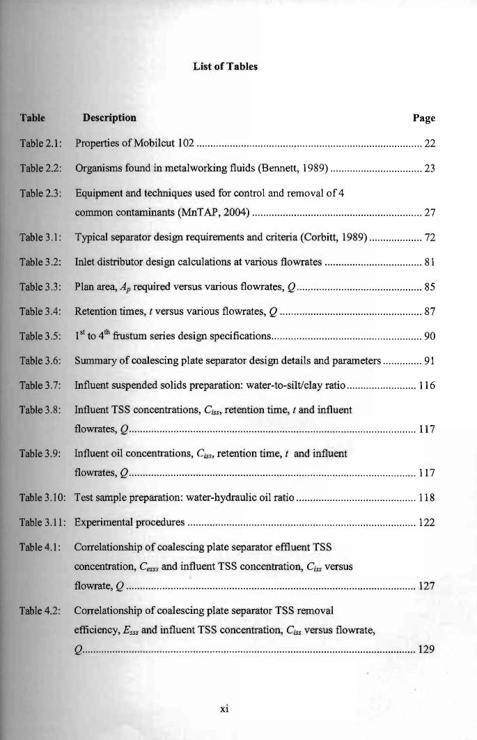
Table 2.1: Properties of Mobilcut 102 ................................. ................................................ 22
Table 2.2: Organisms found in metalworking fluids (Bennett, 1989)
1st 4th fro . d· ·fi· 90
................................. 23
Table 2.3: Equipment and techniques used for control and removal of4
common contaminants (MnTAP, 2004) ................. ............................................ 27
Table 3.1: Typical separator design requirements and criteria (Corbitt, 1989) ................. .. 72
Table 3.2: Inlet distributor design calculations at various flowrates ................................... 81
Table 3.3: Plan area, Ap required versus various flowrates, Q............................................. 85
Table 3.4: Retention times, t versus various flowrates, Q................................................... 87
Table 3.5: to sturn senes eSlgn speCI catIOns..................................................... .
Table 3.6: Summary of coalescing plate separator design details and parameters .............. 91
Table 3.7: Influent suspended solids preparation: water-to-siltlclay ratio
Table 3.8: Influent TSS concentrations, Css, retention time, t and influent
......................... 116
flowrates, Q....................................................................................................... 117
Table 3.9: Influent oil concentrations, Ciss , retention time, t and influent
flowrates, Q....................................................................................................... 117
Table 3.10: Test sample preparation: water-hydraulic oil ratio ........................ ................... 118
Table 3.11 : Experimental procedures ............................................................ ...................... 122
Table 4.1: Correlationship of coalescing plate separator effluent TSS
concentration, Cesss and influent TSS concentration, Ciss versus
flowrate, Q........................................................................................................ 127
Table 4.2: Correlationship of coalescing plate separator TSS removal
efficiency, Esss and influent TSS concentration, Css versus flowrate,
Q........................................................................................................................ 129
Xl

Table 4.3: Coalescing plate separator TSS removal efficiency, Esss at different
influent TSS concentrations, Css and flowrates, Q; Average TSS
removal efficiency and removable particle size at different flowrates,
Q.................................. .. ......... .......... ................................................................. 130
Table 4.4: Correlationship of coalescing plate separator effluent oil
concentration, Ceos and influent oil concentrations, Cia versus
Table 4.5: Correlationship of separator tank oil removal efficiency, Eos and
Table 4.6: Capital and operation/maintenance costs of MRS & CNC filtration
Table CI0: Effluent oil concentration, TSS level and lubricity of recycled MWF
after filtration, separation and aeration processes at dilution ratio
flowrates, Q .......... .. ..... .................... .......... ....................................... .......... ....... 135
influent oil concentration, Co for various flowrates, Q ......................... ........... 138
system .................................................................. ............................................. 155
Table 4.7: Cash flow - CNC filtration system and MRS ................................................... 157
Table 4.8: Accumulated cash flow - CNC filtration system and MRS ............... .................. 157
Table C 1: Initial Lengths, Lo of the three springs .............................................................. 179
Table C2: Load and corresponding elongation for Spring 1 ...... .. ..................................... 179
Table C3: Load and corresponding elongation for Spring 2 ..................................... ........ 179
Table C4: Load and corresponding elongation for Spring 3 ............................................. 180
Table C5: TSS removal efficiency of filtration tank ............................ .. ........................... 180
Table C6: TSS removal efficiency of coalescing plate separator ..................................... 181
Table C7: Coalescing plate separator influent oil concentration, Cio, effluent oil
concentration, Ceos, oil removal efficiency, Eos at different flowrates,
Q......... ............................................................................................................... 182
Table C8: Initial oil concentration, TSS level and friction coefficient.. ............................ 183
Table C9: Correlationship ofTSS concentration and friction coefficient.. ....................... 183
1:100 (MRS) ..................................................................................................... 184
Xll

Table C11: Effluent oil concentration, TSS level, lubricity and bacteria counts
for spent MWF after filtration, separation and aeration processes
with single concentration adjustment ........ .. .......................... .......... .......... ....... 185
Table C1 2: Effluent oil concentration, TSS level, lubricity and bacteria counts
for spent MWF after filtration, separation and aeration processes
(concentration adjusted for every run) .................................. .. .......................... 186
Table Cl3: Effluent oil concentration, TSS level, lubricity and bacteria counts of
ELITE CNC samples ........................................................................................ 187
Table C14: Polyfelt TS 20 Geotextiles - Technical Data .................................................... 188
Xlll

List of Figures
Figure Description Page
Figure 1.1: The 4-Stage Recycling System for MWFs ........................................................... 6
Figure 1.2: Enhanced circular gravity coalescence separator with series of
conical parallel coalescence frustums alternately arranged in upright
and inverted positions ........................... .... ............................................................ 8
Figure 1.3: Forces acting on oil droplets while sliding along coalescing plates, in
which Fs = buoyancy force and Fb= drag force .................................................. 10
Figure 1.4: Mechanism ofOil-Coolant-Solids removal by Inclined Parallel
Coalescing Plates ................................................................................................ 13
Figure 2.1: (a) Mobilcut 102 in 20L bucket, (b) Mobi1cut 102 in amber clear
color and (c) Milky emulsion of Mobi1cut 102 when mixed with
water.................................................................................................................... 20
Figure 2.2: Schematic diagram of Centrifuge typically used for tramp oil
removal (Bray, 2001) .............................................................................. .... ........ 3 1
Figure 2.3: Typical flow through a hydro cyclone (lAMS and WRATT, 2005) ................... 34
Figure 2.4: Schematic diagram of centrifuge used for particle separation (Bray,
2001) ............................ ... .................................................................................... 35
Figure 2.5: Comparison ofparticle settling characteristics in a vertical tube and
an inclined tube (RPI, 1996) ............................................................................... 43
Figure 2.6: Typical API separator (Wikipedia, 2009) ........ ................................................... 45
Figure 2.7: Inclined plate rectangular separator (Mohr, 1992) ................. ............................ 47
Figure 2.8: Flat corrugated plates (Mohr, 1992) ................................................................... 48
Figure 2.9: Typical multiple angle coalescing pack (Mohr, 1992) ....................................... 49
Figure 2.10: Packing type separator (Mohr, 1992) ................................................................. 50
XIV

Figure 2.11: Zones of sedimentation: (a) horizontal flow clarifier; (b) up flow
clarifier (Tchobanoglous et al., 2003)................................... .............................. 51
Figure 2.12: Inclined-plate module in (a) rectangular separator and (b) circular
separator (Reynolds, 1982) ...... ... ...................... ................................... .. ...... .. ..... 52
Figure 2.13: Module of inclined tube and its operation (Reynolds, 1982;
Tchobanoglous et aI., 2003) ............................................................................... 53
Figure 2.14: Wire passing over a circular drum (Riley et al., 2002)............... ........................ 54
Figure 2.15: Free body diagram of a small segment of the wire (Riley et aI., 2002).............. 54
Figure 3.1: Coalescing Plate Separator - Dimensional Details ............................................. 70
Figure 3.2: Perry and Green design module horizontal perforated-pipe
distributor (Perry and Green, 1997) .................................................................... 75
Figure 3.3: Ideal circular settling basin, with flowrate (Q), radius (r), depth (h)
and settling velocity of the solid particle or rising velocity of the oil
Figure 3.4: (a) Outlet periphery v-notch overflow weir channel, and (b) Outlet
droplet (v) (Reynolds, 1982) .................... .......................................................... 80
launder design parameters .................................................................................. 87
Figure 3.5: Coalescence frustum design details and parameters ........................................... 89
Figure 3.6: Upflow filtration and aeration units - side elevation and plan ............................ 93
Figure 3.7: Filtration and aeration units - front and rear elevations ...................................... 94
Figure 3.8: Plots of bacteria growth rates versus Time ......................................................... 97
Figure 3.9: Specification details of pasteurization unit.. ....................................................... 99
Figure 3.10: Specifications of test rig for mounting the filtration tank, coalescing
plate separator, aeration-filtration tank and pasteurization unit
(isometric view) ........................................................................................ ... ..... 101
Figure 3.11 : Side elevation of test rig mounted with complete MRS
Figure 3.12: Plan view and Section A-A of the test rig mounted with complete
................................... 102
MRS .................................................................................................................. 103
xv

Figure 3.13: Front view of the test rig mounted with complete MRS ...... .... ......................... 104
Figure 3.14: Experimental setup of MRS: (a) Schematic Process flow, and (b)
Pilot Scale ......................................................................................................... 106
Figure 3.15: Particle size distribution of sieved silt and clay samples (Geospec,
2007) ................................................................................................................. 107
Figure 3.16: Sample collection points; (a) Sample collected from effluent of
mixing tank, (b) Sample collected from effluent of filtration unit, ( c)
Sample collected from effluent of mixing tank and (d) Sample
collected from effluent of coalescing plate separator ....................................... 108
Figure 3.17: Horiba model OCMA-31 0 oil water analyzer and S316 Solvent ..................... 109
Figure 3.18: Spectrophotometer HACH DRl2400 ........................................... .. ............ .. ..... 110
Figure 3.19: Setup in laboratory to determine spring stiffness, k .......................................... 111
Figure 3.20: Applied loads and corresponding elongation of 3 springs ................................ 113
Figure 321: Ring lubricity test in laboratory ..................................... ... ........................ ... ..... 114
Figure 3.22: Schematic diagram for lubricity test and its free body diagram .......... .. ........... 114
Figure 4.1: Up flow filtration unit - TSS removal efficiencies, EssjvS time at
flowrates 1.0x10⁻⁵ and 0.5xlO-5 m3/s ............................. .. ................................. 124
Figure 4.2: Extrapolation ofminimum removable particle size of upflow filter
medium that consists of 5 layers of TS20 geotextile ..... ................................... 124
Figure 4.3 : Coalescing plate separator effluent TSS concentrations, Cesss at
different influent TSS concentrations, Ciss and flowrates, Q ... .............. .... ....... 125
Figure 4.4: Plots of power relationship of coalescing plate separator effluent
TSS concentrations, Cesss and influent TSS concentrations, Ciss for
various flowrates, Q............ ............... ............................................................... 126
Figure 4.5: Coalescing plate separator TSS removal efficiencies, Esss at different
influent TSS concentrations, C;ss and flowrates, Q........................................... 128
xvi
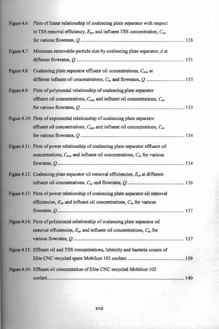
Figure 4.6: Plots of linear relationship of coalescing plate separator with respect
to TSS removal efficiency, Esss and influent ISS concentration, C iss
for various flowrates, Q........................... ......................................................... 128
Figure 4.7: Minimum removable particle size by coalescing plate separator, d at
different flowrates, Q.................................................................... .................... 13 1
Figure 4.8: Coalescing plate separator effluent oil concentrations, Ceos at
different influent oil concentrations, C io and flowrates, Q ........ .. ..................... 133
Figure 4.9: Plots ofpolynomial relationship of coalescing plate separator
effluent oil concentrations, Ceos and influent oil concentrations, C io
for various flowrates, Q .................... ......................................... ....................... 133
Figure 4.1 0: Plots of exponentiai relationship of coalescing plate separator
effluent oil concentrations, Ceos and influent oil concentrations, Co
for various flowrates, Q .................................................................................... 134
Figure 4.11: Plots ofpower relationship of coalescing plate separator effluent oil
concentrations, Ceos and influent oil concentrations, C io for various
flowrates, Q....................................................................................................... 134
Figure 4.12: Coalescing plate separator oil removal efficiencies, Eos at different
influent oil concentrations, Cio and flowrates, Q .............................................. 136
Figure 4.1 3: Plots of power relationship of coalescing plate separator oil removal
efficiencies, Eos and influent oil concentrations, Cio for various
flowrates, Q....................................................................................................... 137
Figure 4.14: Plots of polynomial relationship of coalescing plate separator oil
removal efficiencies, Eos and influent oil concentrations, C io for
various flowrates, Q.......................................................................................... 137
Figure 4.15: Effluent oil and TSS concentrations, lubricity and bacteria counts of
Elite CNC recycled spent Mobilcut 102 coolant ....................................... ... .... 139
Figure 4.1 6: Effluent oil concentration of Elite CNC recycled Mobilcut 102
coolant. .......................................................... .. .................................... ..... .. ... .... 140
XVll

Figure 4.17: Effluent TSS concentration of Elite CNC recycled Mobilcut 102
Figure 4.20: Initial concentrations of oil, Cino, SS, Cnss and lubricity, J.ls of fresh
Figure 4.22: Effluent oil levels after filtration, separation and aeration for coolant
Figure 4.23: Effluent TSS levels after filtration, separation and aeration for
Figure 4.24: Effluent friction coefficient after filtration, separation and aeration
Figure 4.25: Effluent concentrations of oil and TSS, and lubricity after filtration,
Figure 4.26: Effluent oil and TSS concentrations, and lubricity (with one
Figure 4.30: Oil and TSS concentrations, lubricity and bacteria counts after each
run for recycled coolant (9 runs with influent adjustment during each
coolant............................................................................................................... 140
Figure 4.18: Effluent friction coefficient of Elite recycled Mobi1cut 102 coolant.. .............. 141
Figure 4.1 9: Effluent bacteria counts of Elite recycled Mobilcut 102 coolant ..................... 141
coolant for different coolant-water dilution ratios ............................................ 142
Figure 4.2 1: Lubricity of fresh coolant at dilution ratio 1: 1 00 for different TSS
concentrations ................................................................................................... 143
at dilution ratio 1: 100 and circulated through MRS for 10 runs ....................... 145
coolant at dilution ratio 1: 100 and circulated through MRS for 10
runs....................................................... ... ......... .. ............................................... 146
for coolant at dilution ratio 1: 1 00 and circulated through MRS for 10
runs.................................................................................................................... 146
separation and aeration for coolant at dilution ratio 1: 1 00 and
circulated through MRS for 10 runs ................................................................. 147
concentration adjustment) ................................................................................. 148
Figure 4.27: Effluent oil concentrations (with one concentration adjustment) ..................... 149
Figure 4.28: Effluent TSS concentrations (with one concentration adjustment) .................. 149
Figure 4.29: Effluent lubricity (with one concentration adjustment) .................................... 150
run) .................................................................................................................... 151
XVlll

I
Figure 4.31: Effluent oil concentrations after filtration, separation and aeration for
recycled coolant (9 runs with influent adjustment during each run) ..... ........... 152
Figure 4.32: Effluent TSS concentrations after filtration, separation and aeration
for recycled coolant (9 runs with influent adjustment during each
run) .... .................................................................................................. .. ............ 152
Figure 4.33: Effluent lubricity after filtration, separation and aeration for recycled
coolant (9 runs with influent adjustment during each run) ............................... 153
XIX
I
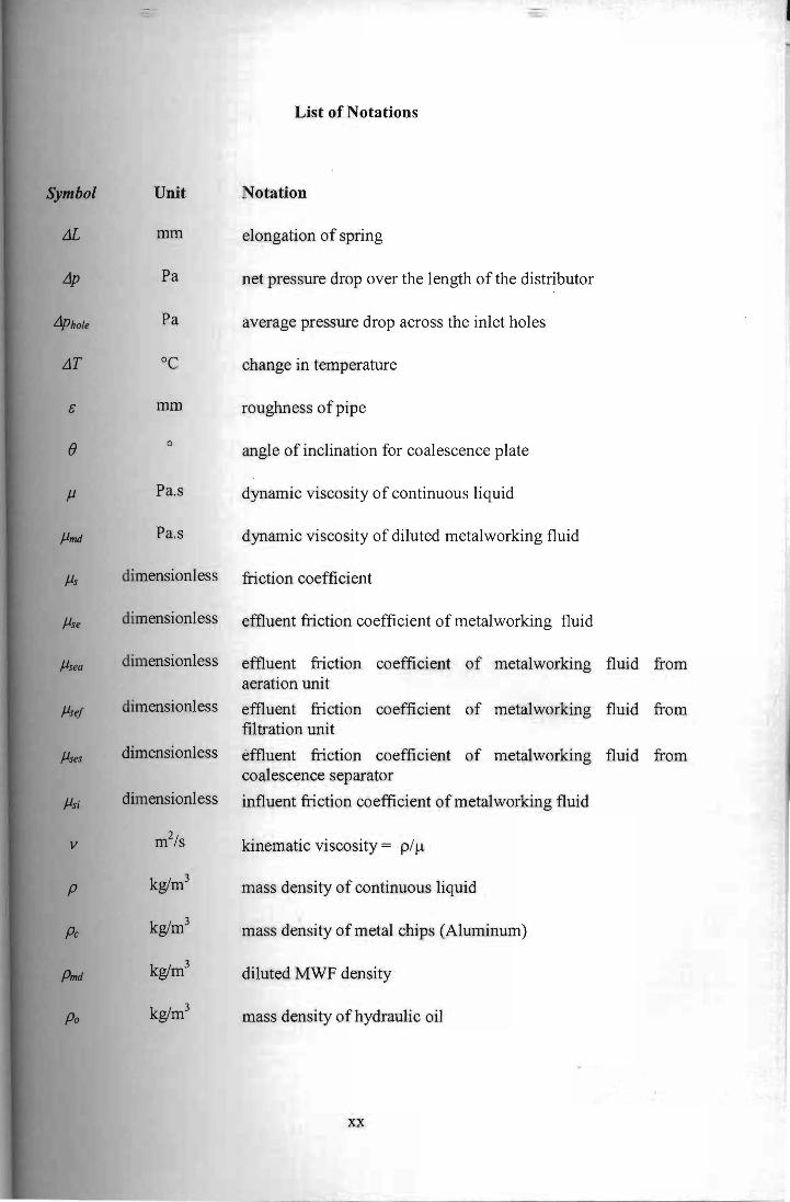
List of Notations
Symbol Unit Notation
JL mm elongation of spring
Lip Pa net pressure drop over the length of the distributor
Liphole Pa average pressure drop across the inlet holes
LlT °c change in temperature
c mm roughness of pipe
8 ° angle of inclination for coalescence plate
J.l Pa.s dynamic viscosity of continuous liquid
J.lmd Pa.s dynamic viscosity of diluted metalworking fluid
J.ls dimensionless friction coefficient
J.lse dimensionless effluent friction coefficient of metalworking fluid
J.lsea dimensionless effluent friction coefficient of metalworking fluid from aeration unit
/1se! dimensionless effluent friction coefficient of metalworking fluid from filtration unit
J.lses dimensionless effluent friction coefficient of metalworking fluid from coalescence separator
J.lsi dimensionless influent friction coefficient of metalworking fluid
v m2/s kinematic viscosity = p/J.!
p kglm3 mass density of continuous liquid
pc kglm3 mass density of metal chips (Aluminum)
Pmd kglm3 diluted MWF density
po kglm3 mass density of hydraulic oil
xx

I
Pslo kglm3
mass density of solid particles or oil droplets
¢ dimensionless shape factor (oil droplet and solid particle)
Ac m 2
inlet perforated-pipe cross-sectional area
Ahole m 2
total inlet hole area of the distributor
Ap m 3 plan area of coalescence separator
a m coalescing plate top view area width
C mglL concentration of oil or total suspended solids
Ceoa mglL effluent oil concentration from aeration unit
Ceo! mglL effluent oil concentration from filtration unit
Ceas mglL effluent oil concentration from coalescence separator
CtSSQ mglL effluent suspended solids concentration from aeration unit
Cess! mglL effluent suspended solids concentration from filtration unit
Cesss mglL effluent suspended solids concentration from coalescence separation
Cio mglL influent oil concentration
CUS mglL influent suspended solids concentration
Co mglL concentration of oil
Cp J/g.oC specific heat
Css mglL concentration of total suspended solids
d m diameter of solid particle or oil droplet
D m diameter of coalescence separator
Db m outlet baffle diameter
Di m inner diameter of coalescence frustum
Do m outer diameter of coalescence frustum
XXI