development of an embeddable reference · pdf filefinal contract report development of an...
TRANSCRIPT
FINALCONTRACT REPORT
DEVELOPMENT OF ANEMBEDDABLE REFERENCE ELECTRODE
FOR REINFORCEDCONCRETE STRUCTURES
LEIGH ANN PAWLICKGraduate Research Assistant
Center for Electrochemical Science & EngineeringDepartment of Materials Science & Engineering
University of Virginia
GLEN E. STONERProfessor and Director
Center for Electrochemical Science & EngineeringDepartment of Materials Science & Engineering
University of Virginia
""'"GERARDO G. CLEMENAPrincipal Research Scientist
Virginia Transportation Research Council
V·I·R·G·I·N· I·A
TRANSPORTATION RESEARCH COUNCIL
VIRGINIA TRANSPORTATION RESEARCH COUNCIL
FINAL CONTRACT REPORT
DEVELOPMENT OF AN EMBEDDABLE REFERENCE ELECTRODEFOR REINFORCED CONCRETE STRUCTURES
Leigh Ann PawlickGraduate Research Assistant
Center for Electrochemical Science & EngineeringDepartment of Materials Science & Engineering
University of Virginia
Glenn E. StonerProfessor & Director
Center for Electrochemical Science & EngineeringDepartment of Materials Science & Engineering
University of Virginia
Gerardo G. ClemefiaPrincipal Research Scientist
Virginia Transportation Research Council
(The opinions, findings, and conclusions expressed in thisreport are those of the authors and not necessarily those of
the sponsoring agency)
Contract Research Sponsored byVirginia Transportation Research Council
Virginia Transportation Research Council(A Cooperative Organization Sponsored Jointly by the
Virginia Department of Transportation andthe University of Virginia)
Charlottesville, Virginia
November 1998VTRC 99-CR1

NOTICE
The project that is the subject of this report was done under contract for the VirginiaDepartment of Transportation, Virginia Transportation Research Council. The opinionsand conclusions expressed or implied are those of the contractors, and, although theyhave been accepted as appropriate by the project monitors, they are not necessarily thoseof the Virginia Transportation Research Councilor the Virginia Department ofTransportation.
Each contract report is peer reviewed and accepted for publication by Research Councilstaff with expertise in related technical areas. Final editing and proofreading of the reportare performed by the contractor.
Copyright 1998, Virginia Department of Transportation.

ABSTRACT
There is a concern that none of the existing concrete-embeddable reference electrodes thatare being used as a convenient means for monitoring the condition of the reinforcing steel inconcrete bridges or the operation of cathodic protection systems for permanently halting steelcorrosion in these structures may have sufficient stability of at least 25 years. This studyexamines the possibility of using stable-potential galvanic couples (SPGC), which rely ondifferent rate constants between the component metals of each couple to maintain stablepotentials, as a new concept for developing better concrete-embeddable reference electrodes.Each SPGC relies on the different rate constants between the component metals to maintain acharacteristic stable potential and can be classified as either noble-noble, noble/active-passive,noble-active or active-active.
The long-term and the short-term stability of the potentials of different galvanic couples(in saturated calcium hydroxide), relative to both a saturated calomel electrode and a commercialmanganese dioxide electrode, were assessed. The cathode-to-anode area ratio aspects of somecouples were also investigated and it was determined that the area ratio could be used to optimizecouple stability. Mixed potential theory was used to characterize these electrodes and explain thestability behavior. Several potentially successful couples, that exhibited potential shifts of lessthan 10mV, were identified and embedded in concrete (both with and without added chloride)for further investigation.
This resulted in the identification of three promising candidate couples (Cu-W, Ni-W,and Cu-Ni) that can be developed into very stable concrete-embeddable reference electrodes byoptimizing the electrode design parameters such as anode-to-cathode area ratio and geometry.
iii


FINAL CONTRACT REPORT
DEVELOPMENT OF AN EMBEDDABLE REFERENCE ELECTRODEFOR REINFORCED CONCRETE STRUCTURES
Leigh Ann PawlickGraduate Research Assistant
Center for Electrochemical Science & EngineeringDepartment of Materials Science & Engineering
University of Virginia
Glenn E. StonerProfessor & Director
Center for Electrochemical Science & EngineeringDepartment of Materials Science & Engineering
University of Virginia
Gerardo G. ClemeiiaPrincipal Research Scientist
Virginia Transportation Research Council
INTRODUCTION
The premature deterioration of many of the almost 600,000 bridges in existence in theUnited States as of 1995, as well as other reinforced concrete systems, gives rise to the growingconcern about corrosion resistance in reinforced concrete. The reinforcing steel in concrete isprotected by the alkalinity of the environment, but the ingress of chloride ions into the concretehas been found to prompt the breakdown of the passivity of the steel. The resulting corrosionproducts are larger in volume than the original steel by up to eight times. The increased volumeplaces stress on the surrounding concrete and in severe cases may result in the spalling of theconcrete cover. The deterioration of reinforced concrete structures increases each year as moredeicing salts are deposited on roadways and environmental factors such as sea spray continue toadd corrosive species to the structures.
A widely used method for assessing the possibility of corrosion on the reinforcing steel ina concrete structure is the measurement of the potential of the steel using a half cell or referenceelectrode. The underlying principle of this method is that corrosion involves an exchange ofenergy within different sections of the reinforcing steel; and, the relative energy levels can bedetermined in relation to a reference electrode with a stable electrochemical potential. Eventhough the potential of the steel in a structure is not a measure of the rate of corrosion of thesteel, potential measurement made on the top surface of a concrete structure with a portablereference electrode (typically copper-copper sulfate electrode) is very useful and reliable for
delineating anodic and cathodic areas on the reinforcing steel, especially when used with othernondestructive or semidestructive inspection techniques.
In contrast to portable reference electrodes that are moved from point to point on thesurface of the concrete structure, reference electrodes that can be embedded in concrete structuresoffer a unique advantage, in that they can be placed relatively close to the steel and, thereby,reduce errors in the measured potential caused by the resistance of the concrete. Even though thepotentials measured by an embedded reference electrode are reflective only of the condition ofthe steel in its immediate vicinity, it is a very convenient way for monitoring the steelreinforcement because the need for traffic control to place a portable reference electrode on thesurface of the concrete is eliminated.
In addition, embedded reference electrodes are extremely valuable for long-termevaluation of the performance of cathodic protection (CP) systems, since protection criteria arebased upon shifts in the potential of the reinforcing steel. Furthermore, the greatest advantage ofpermanently embedded reference electrodes may be in their use to control the rectifiers and,therefore, the amount of applied current or potential at a "safe" level. This is particularlyimportant in cathodic protection of prestressed concrete members, where overprotection of thehigh-strength prestressed steel tendons can cause generation of excessive hydrogen and, possibly,subsequent embrittlement of the tendons. Use of embedded reference electrodes also facilitatesthe use of remote monitoring devices that significantly reduce the need to visit bridge sites and,therefore, the cost of monitoring CP systems.
In general, a good reference electrode must have the following characteristics: (a) isgoverned by a reversible equilibrium that follows the Nernst equation, (b) have a stable potentialthat returns to a reversible value after any passage of small current through the electrolyte, (c)maintains a constant potential in spite of changes in temperature and moisture, (d) be rugged andpermanent, (e) be reasonably small and unobtrusive to allow easy placement in a structure and (t)be inexpensive. Although many types of electrodes have been tested, none have been completelysuccessful; in fact, there have been indications that some types of electrodes have becomeunstable after only several years of embeddment in concrete. 1
,2 In view of the important role thatembeddable reference electrodes have in the effective operation of CP systems, it is clear thatdevelopment of a new effective and stable reference electrode is critical.
Galvanic couple reference electrodes represent a new concept in reference electrodetechnology. Unlike traditional reference electrodes, these electrodes are not based onthermodynamically reversible reactions but instead are bi-metallic couples that maintain a stablepotential for a finite period of time. These can be made to be both rugged and cost effective.Furthermore, their stability is based on the specific environment of concrete, and can beexplained and calibrated with electrochemical theory. In view of the potential application of thisnew type of electrodes in concrete, an investigation was recently conducted with the objective ofidentifying several viable galvanic couple electrodes that exhibit stable potentials formeasurement in reinforced concrete and verifying the concept of potential stable galvanic coupleelectrodes in concrete. This report discusses the fundamentals of reference electrodes and theresults of the investigation into the behaviors of a number of candidate galvanic-couple
2
electrodes in saturated calcium hydroxide solution and a selected subset of these electrodes inconcrete. Electrode performance was analysed further by determining deaeration, chloride, andmicro-polarization effects.
BACKGROUND
In any corroding system, the electrochemical reactions involved are defined by theircharacteristic potentials. As the passivity of the reinforcing steel breaks down, as a result ofaccumulation of chloride ions and shifts in pH and oxygen concentration in the concrete, acorresponding shift occurs in the electrochemical potential of the steel-and-concrete system. Bymonitoring the open-circuit potential of the steel, the corrosion state and behavior of thereinforcing steel can be determined without destroying the concrete structure. However, in allelectrochemical systems, it is impossible to measure the absolute potential of a single electrodeor reaction. For steel in concrete, this means that the absolute potential of the steel/concreteinterface cannot be determined simply with the steel electrode alone; instead, it must bedetermined as the potential difference between the steel half-cell or electrode and an additional,separate electrode, which is called the reference electrode. Likewise, the "known" potential ofthis reference electrode is defined relative to a standard hydrogen electrode, which has a potentialarbitrarily assigned as zero. To this end, the reference electrodes must be stable with time,reproducible, and unaffected by small currents that may be passed through the interfaces thatconstitute the reference electrodes in an electrochemical system.
Therefore, good reference electrodes, when embedded in concrete structures exposed tocorrosive environments, provide a convenient, nondestructive means of monitoring theelectrochemical parameters that govern the corrosion of steel in the concrete.
Existing Concrete-Embeddable Reference Electrodes
Several reference electrodes have been designed for, tested, and used in concretestructures. These reference electrodes can be classified as either (1) true reference electrodes,which include silver/silver chloride (SSC), manganese dioxide/manganese trioxide(Mn02/Mn203) and copper/copper sulfate (CSE) electrodes, or (2) pseudo-reference electrodes,which include noble metal, mixed metal oxide, activated titanium, and graphite electrodes.
True Reference Electrodes
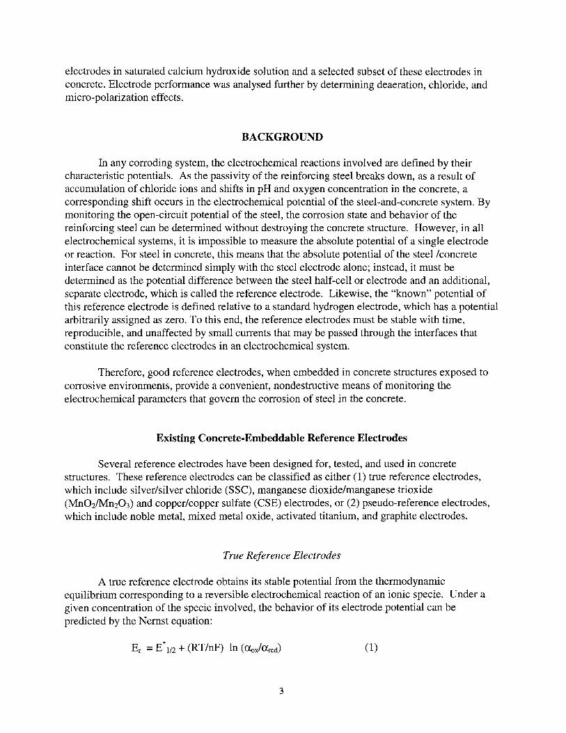
A true reference electrode obtains its stable potential from the thermodynamicequilibrium corresponding to a reversible electrochemical reaction of an ionic specie. Under agiven concentration of the specie involved, the behavior of its electrode potential can bepredicted by the Nernst equation:
Er =E*1/2 + (RT/nF) In (Uox/ared)
3
(1)
where Er is the electrode's reference potential, E*1/2 is the standard equilibrium potential for thehalf-cell reaction at 25° C, Clox and Clred are the activities of the oxidized and reduced speciesrespectively, and R, T and F are the gas constant, temperature and Faraday's constant,respectively. As indicated by the Nernst equation, a true reference electrode requires a constantconcentration of a given species to maintain a stable reference potential. The structure of a truereference electrode, therefore, generally consists of a metal wire in contact with an electrolytemedium that contains the active ionic species. In some cases, the metal ion is dissolved in theelectrolyte solution, and in other cases the metal ion is contained in a salt film on the metal. Forexample, a silver/silver chloride (SSC) electrode consists of a silver wire covered with adeposited layer of silver chloride in solution with a chloride rich electrolyte. For this instance,the following reaction is maintained in equilibrium:
Ag + cr ~ AgCI + e- . (2)
With a chloride concentration of 1.0 M, the reference potential is maintained at 0.235V, versus anormal hydrogen electrode.3
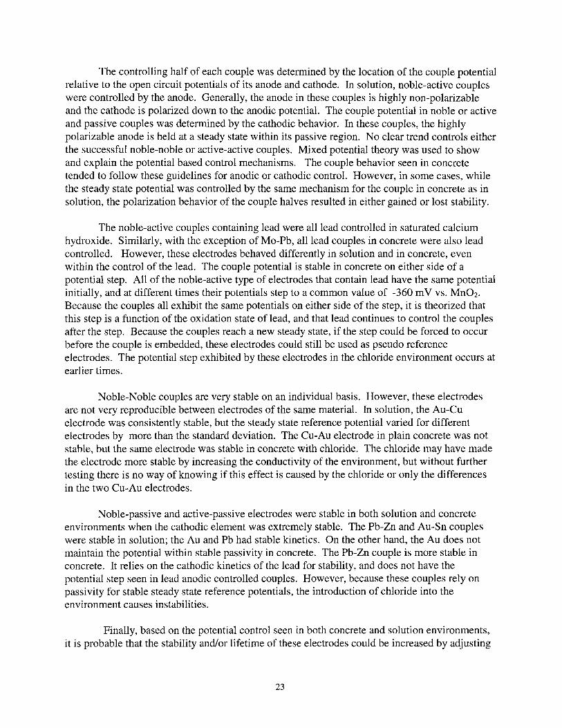
Both SSC and Mn02 electrodes have been redesigned specifically for embedding inconcrete, and extensive data exist about their performance.2,4,s Copper sulfate electrodes havebeen used extensively as surface electrodes, but only limited data are available about the behaviorof this electrode while embedded. As mentioned earlier, SSC require a chloride concentrationcell to maintain a stable reference potential. However, because these electrodes are embedded inconcrete, the standard glass encasing for liquid or gel electrolytes is not feasible. Embeddablesilver chloride electrodes have been designed with a chloride rich electrolyte surrounded by abackfill that is contained in a concrete compatible form, usually a cotton bag.3 Figure 1 showsthe structure of an embeddable SSC electrode.
Similarly, copper sulfate electrodes require a supply of copper ions. Because few of theseelectrodes have been embedded, the design for an embeddable copper sulfate electrode consistsmerely of a plastic (rather than glass) sheath for the copper ion containing electrolyte.2
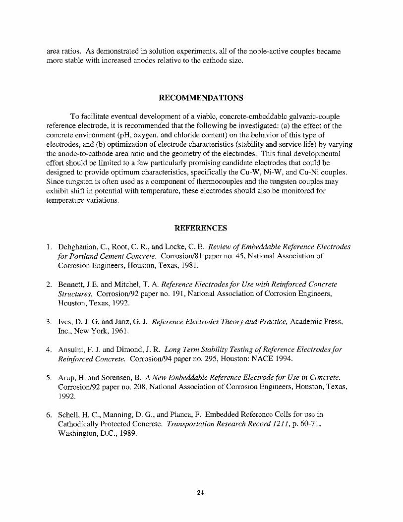
Manganese dioxide reference electrode, which is based on the reaction between Mn02and Mn203 in an alkaline environment, has been used in alkaline battery technology for manyyears, and its stability has been well established. For compatibility with concrete, the electrodehas a mortar tip, and the alkaline components of the electrode are housed in a polymer/metalcasing to provide an electrical contact.S Figure 2 shows a manganese dioxide reference electrodethat is designed for use in concrete.
Even though these true reference electrodes provide all of the characteristics required fora good electrode, they do not behave as precisely in concrete as predicted by laboratory use. Thisis because none of these electrodes are based on the components found in concrete. Schell et aledetermined that SSC electrodes suffer from two main problems in concrete: (a) the diffusion ofchloride ions away from the electrode results in poor stability over extended time periods, and (b)
6the electrode tends to be unstable at cold temperatures.
4
Arup et aI., who developed the manganese dioxide electrode, found it to be an acceptablereference electrode because it could be embedded with minimal liquid junction potential errors.5
The manganese electrodes tested showed little deviation in reference potential betweenelectrodes. Also, they found the manganese electrode to be stable even in mortar that had beendeaerated by cathodic protection. Ansuini and Diamond found the manganese dioxide referenceto be stable with time after two years in concrete both with and without chloride contamination.4
Myrdal and Videm found the manganese dioxide reference to be acceptable as well, but theynoted that the reference potential was altered by pH shifts.?
It should be noted that most of these true reference electrodes perform well whendesigned, handled, and constructed properly; however, the proper design of the electrodes oftenmeans limiting their usage. Due to the complexity of the electrodes, they tend to be relativelyexpensive and are generally bulky. Both of these qualities make these electrodes difficult toapply extensively and cost effectively to cathodic protection systems.6
Pseudo Reference Electrodes
More pseudo reference electrodes than true reference electrodes have been used inreinforced concrete systems to determine potential distribution within the structure, because theseelectrodes tend to be durable for standard construction procedures and stable. Since they aresimple to construct in various sizes, these electrodes are relatively less expensive. However,there are various drawbacks as well as the advantages to using these electrodes.
Pseudo reference electrodes are stable potential cells that do not have an identifiablereversible electrochemical reaction, such as the previous example for the sse electrode. Thebehavior of these electrodes is not predictable by the Nernst equation, but can be shown, in somecases, to be stable through empirical observation. In some cases, the pseudo electrodes arecorroding systems whose behavior may be explained by mixed potential theory. However, mostof the data available for these electrodes are strictly empirical stability behavior and little dataexist to explain the electrode potentials and potential shifts using theory. All pseudo referenceelectrodes are stable only in very specific environments. For instance, a pseudo referenceelectrode for concrete would not necessarily provide a stable reference potential in a less alkalinesystem, whereas a true reference electrode would generally be unaffected by a change inenvironment. While the true reference electrodes will have a liquid junction potential created bythe interface of the electrode's electrolyte and the environment, pseudo reference electrodes donot have a liquid junction potential error because they rely on the pore solution for stability.Acceptable pseudo reference electrodes will vary only slightly with small changes in concreteporewater over time.
Several types of pseudo electrodes have been tested and some even implemented inconcrete systems. These include several elemental electrodes (such as lead, gold, platinum, zincor graphite) as well as mixed metal oxide (MMO) and titanium oxide electrodes. Some MMOelectrodes are now commercially available.
5
For ease of implementation, pseudo reference electrodes can be designed quite simplywith only a single element, i.e., consisting merely of the metal and an electrical connection to apotential monitoring system. Several single-metal pseudo reference electrodes that have beenexamined include gold, platinum, palladium, silver, nickel, stainless steel, and lead. White foundthat gold and platinum electrodes, although stable, were strongly influenced by oxygen and pHshifts.8 Similarly, Myrdal et al. found that the potential of platinum was strongly affected byoxygen partial pressure, but lead was not as sensitive.7 These investigators also determined thatplatinum, palladium, nickel, silver, gold and Type 316 stainless steel in concrete either lackedshort term stability, were not consistent between electrodes, or/and did not return to theirrespective reference potentials after immersion in water.7
Graphite electrodes are similar in structure to noble metal electrodes. As illustrated inFigure 3, they consist mainly of a graphite block with a soldered connection to an electrical wire.The electrical connection is then protected with an epoxy plug. Schell et ale found that thepotential of embedded graphite electrodes withstands large variations in temperature and in awide range of chloride content.6 However, Ansuini et al. reported that graphite electrodes wereonly stable for about 3 months, and that over a period of 3 years the graphite electrodes deviatedover a 100-mV span. They concluded that graphite cells should be used only for short-termrelative measurements, such as the depolarization test.4 A separate study by Myrdal et al.concluded that while stable for up to a year, graphite electrodes tend to be sensitive to bothoxygen and pH shifts7
. Furthermore, since the specific reactions that determine the characteristicpotential of this electrode are not well defined, there is another concern that concrete pore watercomposition (specifically, varying ion content) may alter the reaction behavior and thus thepotential.6
Commercially available pseudo reference electrodes are of the mixed metal oxide (MMO)type. The exact structure of these commercial electrodes is proprietary, but some studies havebeen performed on activated titanium with mixed metal oxide surfaces. The activated titaniumelectrodes consist of a titanium rod that is covered with a mixed metal oxide of iridium. Thereaction occurring on the surface should coincide with the following reaction:
(3)
Castro et al. found these electrodes to be acceptable embeddable reference electrodes - being lessdependent on oxygen partial pressure than graphite is in neutral and high pH solutions, andappeared to have short- and long-term stability in concrete as wel1.9 Bennett et al. also foundMMO electrodes to be suitable references, with reproducibility between electrodes ofapproximately 10 mY, and satisfactory behavior during micro-polarizability and hysteresis tests.2
On the other hand, Arup and Sorensen found activated titanium electrodes to be strongly affectedby deaeration and by cathodic polarization while embedded in concrete.5
6
Galvanic Couple Reference Electrodes
Galvanic couple reference electrodes (GCRE) are new pseudo reference electrodes thatare based on a similar concept to graphite reference electrodes. These electrodes can be morestable and predictable than graphite and would be less expensive than true reference electrodes.
A galvanic couple is created when two dissimilar metals are electrically in contact witheach other (providing an electronic path) and surrounded by an electrolyte that provides an ionicpath. To maintain conservation of charge in all galvanic couples, the total reduction current mustequal the total oxidation current - a condition which leads to the polarization of both metals to acombined potential Ecouple.l0 Figure 4 shows an Evans diagram to illustrate the polarizationbehavior of a set of couple halves (metals M and N) as well as for the entire couple. The morenoble metal in this galvanic couple (M) will be polarized cathodically; therefore, it will referredto as the cathode in this study. Similarly, the more active metal in the couple (N) will bepolarized anodically resulting in a higher dissolution rate of this metal. This half of the electrodewill be termed the anode.
Since the potential of the couple is determined by the point where the total anodic currentis equal to the total cathodic current, and not by the current densities, the area of each couple halfwill have an effect on the couple potential. In other words, for the same current density an anodeof 1 cm2 will produce less total current than an anode of 10 cm2
. This area effect would shift theanodic currents to higher values at the same potentials and would decrease Ecouple by lowering thepoint where the total cathodic and anodic currents intersect. The couple potential could also beaffected by varying the cathodic area. For a galvanic couple reference electrode, this principlemay be applied to create more stable or slower corroding electrodes.
The couple potential (Ecouple) is the steady-state reference potential of a GCRE. To be asuccessful concrete-embeddable electrode, it must not only maintain a steady Ecouple, but as acorroding electrode, other criteria must be met. First, the relevant cathodic and anodic processesmust be understood so that any dependence on a species whose presence and availability inconcrete may vary (e.g., oxygen) will be predictable. Secondly, the electrode must not lose metalor deplete ions from the surrounding environment at high rates.
Theoretically, GCRE should be able to maintain a steady state reference potential thatcould be used as a dependable reference in concrete. Even though the potential of a GCRE cannot be predicted by Nernst equation, it may be predicted from their corresponding surfacereactions, which are more straight forward to define than those on graphite electrodes. Unlikecurrent true reference electrodes, theoretically, GCRE's do not require a supply of certain specificion to maintain a stable potential. Furthermore, theoretically, these electrodes could be made toany size because the area ratio of the anode to the cathode is more important for maintaining astable potential than the total area of the electrode. More important, since the life of a GCREmay be predicted by application of mixed potential theory, its service life in a concrete structurecan be optimized by changing the ratio of the areas of the couple halves. Finally, these electrodescould be made to be mechanically durable and inexpensive.
7
EXPERIMENTAL DESIGNS
Electrode Designs
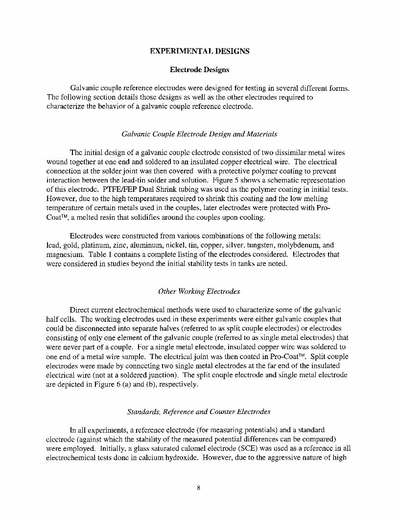
Galvanic couple reference electrodes were designed for testing in several different forms.The following section details those designs as well as the other electrodes required tocharacterize the behavior of a galvanic couple reference electrode.
Galvanic Couple Electrode Design and Materials
The initial design of a galvanic couple electrode consisted of two dissimilar metal wireswound together at one end and soldered to an insulated copper electrical wire. The electricalconnection at the solder joint was then covered with a protective polymer coating to preventinteraction between the lead-tin solder and solution. Figure 5 shows a schematic representationof this electrode. PTFEIFEP Dual Shrink tubing was used as the polymer coating in initial tests.However, due to the high temperatures required to shrink this coating and the low meltingtemperature of certain metals used in the couples, later electrodes were protected with ProCoat™, a melted resin that solidifies around the couples upon cooling.
Electrodes were constructed from various combinations of the following metals:lead, gold, platinum, zinc, aluminum, nickel, tin, copper, silver, tungsten, molybdenum, andmagnesium. Table 1 contains a complete listing of the electrodes considered. Electrodes thatwere considered in studies beyond the initial stability tests in tanks are noted.
Other Working Electrodes
Direct current electrochemical methods were used to characterize some of the galvanichalf cells. The working electrodes used in these experiments were either galvanic couples thatcould be disconnected into separate halves (referred to as split couple electrodes) or electrodesconsisting of only one element of the galvanic couple (referred to as single metal electrodes) thatwere never part of a couple. For a single metal electrode, insulated copper wire was soldered toone end of a metal wire sample. The electrical joint was then coated in Pro-Coat™. Split coupleelectrodes were made by connecting two single metal electrodes at the far end of the insulatedelectrical wire (not at a soldered junction). The split couple electrode and single metal electrodeare depicted in Figure 6 (a) and (b), respectively.
Standards, Reference and Counter Electrodes
In all experiments, a reference electrode (for measuring potentials) and a standardelectrode (against which the stability of the measured potential differences can be compared)were employed. Initially, a glass saturated calomel electrode (SeE) was used as a reference in allelectrochemical tests done in calcium hydroxide. However, due to the aggressive nature of high
8

pH solutions on glass, these electrodes were later replaced with fresh electrolyte every twoweeks. Commercial ERE 20 Manganese Dioxide reference electrodes, produced by ForceInstitutes, were used as standards in all stability tests. This electrode, which is shown to fullscale in Figure 7, has a nominal standard reference potential of +160 mV vs. SCE at 23°C.
In the concrete stability tests, commercial Ag/AgCI electrodes (Electrochemical Devices,Inc.) were used as additional standards to the manganese dioxide reference electrodes. Thenominal reference potential for embeddable SSC electrodes is -20 mV vs. SCE. Finally, for thethree-electrode polarization experiment, where a counter electrode was required, a platinumcoated niobium mesh electrically connected to a platinum coated titanium rod was used.
Experimental Design for Simulated Concrete Solution
To verify that galvanic couple electrodes could maintain consistent reference potentials ina high pH environment, many electrodes were tested at the same time in saturated calciumhydroxide solution. Subsequently, direct current electrochemical methods were performed onindividual couples and single metals to further establish stability and to determine the relevantreaction kinetics. Micro-polarization experiments were performed on specific couples to verifythat the stable reference potentials were unaffected by the application of small currents. Theseexperiments were conducted in succession to show that after small variations in the referencepotential, the original potential could be obtained again. Potentiodynamic tests on single metalsamples were performed to determine the kinetics of the reactions occurring on each couple half.Similarly, potentiodynamic scans were performed with split couples that had been disconnectedafter reaching a steady state while coupled. These tests were designed to determine if the initialpolarized state of the couple would affect the kinetic behavior of each couple half. From theseexperiments, mixed potential theory was used to account for the observed steady state behaviorof the couple. The tank designs, cells and procedures used in these tests are all detailed in thefollowing section.
Stability Tests: Procedure and Tank Design
The stability of each electrode was determined by monitoring the open circuit potentialagainst a saturated calomel electrode in large reservoirs of solution. To avoid unwanted stirringand movement of the electrodes, glass boiling beads (3-6 mm diam., Fisher Scientific) werepacked in the tanks. Figure 8 depicts one of the tanks of electrodes. Each 19-1iter tank contained12 to 16 galvanic couples and a Mn02 electrode in approximately 2.5 liters of solution with a pHof 12.5.
The electrodes were allowed to reach a steady state while immersed in solution atambient temperatures for at least two weeks. The open circuit potentials were then measuredusing a computer controlled data acquisition system. Potentials were taken at least every hourand at most every three minutes (more often if the reading had changed from the previous one)using the Monitor system (data acquisition software used with a multiplexing 16 channel DAQboard). The calomel references were changed and rejuvenated every two weeks. Stabilities for
9
each couple and the Mn02 reference were then determined by calculating the standard deviationsof the open circuit potentials over the last 60 days of 120 days of immersion. Stability tests wereperformed on all electrodes in saturated calcium hydroxide. A limited number of electrodes werethen tested for increasing and decreasing stability with varying anode-to-cathode area ratios (0.1,1.0, and 10).
The tank setup was also implemented to test a limited number of representative electrodesfor stability with small temperature variations. In these cases, six couples at a time wereimmersed with a J type thermocouple in a 1.5-liter tank of glass beads and saturated calciumhydroxide. This tank in turn was placed in a water bath with a temperature-controlling pump.The circulating bath temperatures were held constant (± 0.2 0 C) while the open circuit potentialsand solution temperature were monitored for 24 hours.
Kinetics Experiments: Cell Designs and Procedures
Cell Designs, Hardware, and Software
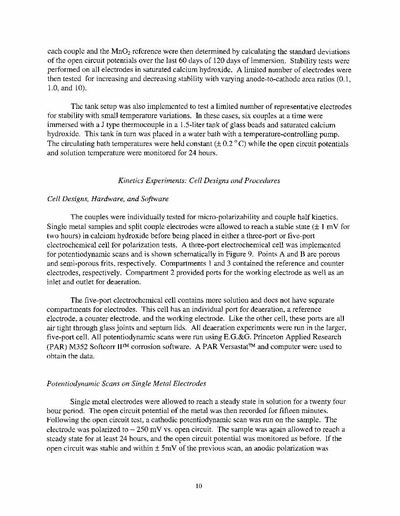
The couples were individually tested for micro-polarizability and couple half kinetics.Single metal samples and split couple electrodes were allowed to reach a stable state (± 1 mV fortwo hours) in calcium hydroxide before being placed in either a three-port or five-portelectrochemical cell for polarization tests. A three-port electrochemical cell was implementedfor potentiodynamic scans and is shown schematically in Figure 9. Points A and B are porousand semi-porous frits, respectively. Compartments 1 and 3 contained the reference and counterelectrodes, respectively. Compartment 2 provided ports for the working electrode as well as aninlet and outlet for deaeration.
The five-port electrochemical cell contains more solution and does not have separatecompartments for electrodes. This cell has an individual port for deaeration, a referenceelectrode, a counter electrode, and the working electrode. Like the other cell, these ports are allair tight through glass joints and septum lids. All deaeration experiments were run in the larger,five-port cell. All potentiodynamic scans were run using E.G.&G. Princeton Applied Research(PAR) M352 Softcorr WM corrosion software. A PAR Versastat™ and computer were used toobtain the data.
Potentiodynamic Scans on Single Metal Electrodes
Single metal electrodes were allowed to reach a steady state in solution for a twenty fourhour period. The open circuit potential of the metal was then recorded for fifteen minutes.Following the open circuit test, a cathodic potentiodynamic scan was run on the sample. Theelectrode was polarized to - 250 mV vs. open circuit. The sample was again allowed to reach asteady state for at least 24 hours, and the open circuit potential was monitored as before. If theopen circuit was stable and within ± SmV of the previous scan, an anodic polarization was
10
applied. The anodic scan began at open circuit and stepped up to + 250 mV vs. open circuit. Inboth scans, the scan rate was 0.166 mV/s and the scan increment was 0.5 mY.
Potentiodynamic Scans on Coupled and Un-Coupled Split Electrodes
Connected split couple electrodes were allowed to reach steady state first in quiescentsolution. A small voltage was then applied over the coupled electrode using the linearpolarization and autoexecute options in the PAR software. A linear polarization loop wascreated to scan from -20 mV against the open circuit to +20 mV against the same open circuit.The reverse scan was then performed immediately to obtain a cyclic scan and the correspondinghysteresis loop.
After the micro-polarization test, the coupled electrode was again allowed to come to asteady state, as determined by two-hour open circuit monitoring. If the couple had not reached asteady state during this time, the open circuit monitoring was repeated as necessary. The splitcouple was then disconnected and the anode was used as the working electrode in a polarizationscan. The anode was polarized from its open-circuit potential to just above the steady statereference potential of the coupled electrode. The scan rate in these experiments was 0.166 mVIsand the scan increment was 1.0 mY.
The electrode was recoupled at the end of the anodic polarization and allowed to reachsteady state in the same manner as before. The couple was again disconnected, and the cathodewas polarized. The cathode was polarized from its open circuit to below the measured opencircuit of the couple or just above the open circuit of the anode whichever was lower. The samescan rates and increments were used in these polarizations as in the anodic polarizations.
Finally, couple kinetics in deaerated solution were determined. The couple wasreconnected and allowed to reach a steady state again in the quiescent solution. Nitrogen wasthen bubbled through the saturated calcium hydroxide for 24 hours to deaerate the solution.After reaching steady state in this solution, the micro-polarizations, cathodic and anodic scanswere repeated in the same manner as in the quiescent solution.
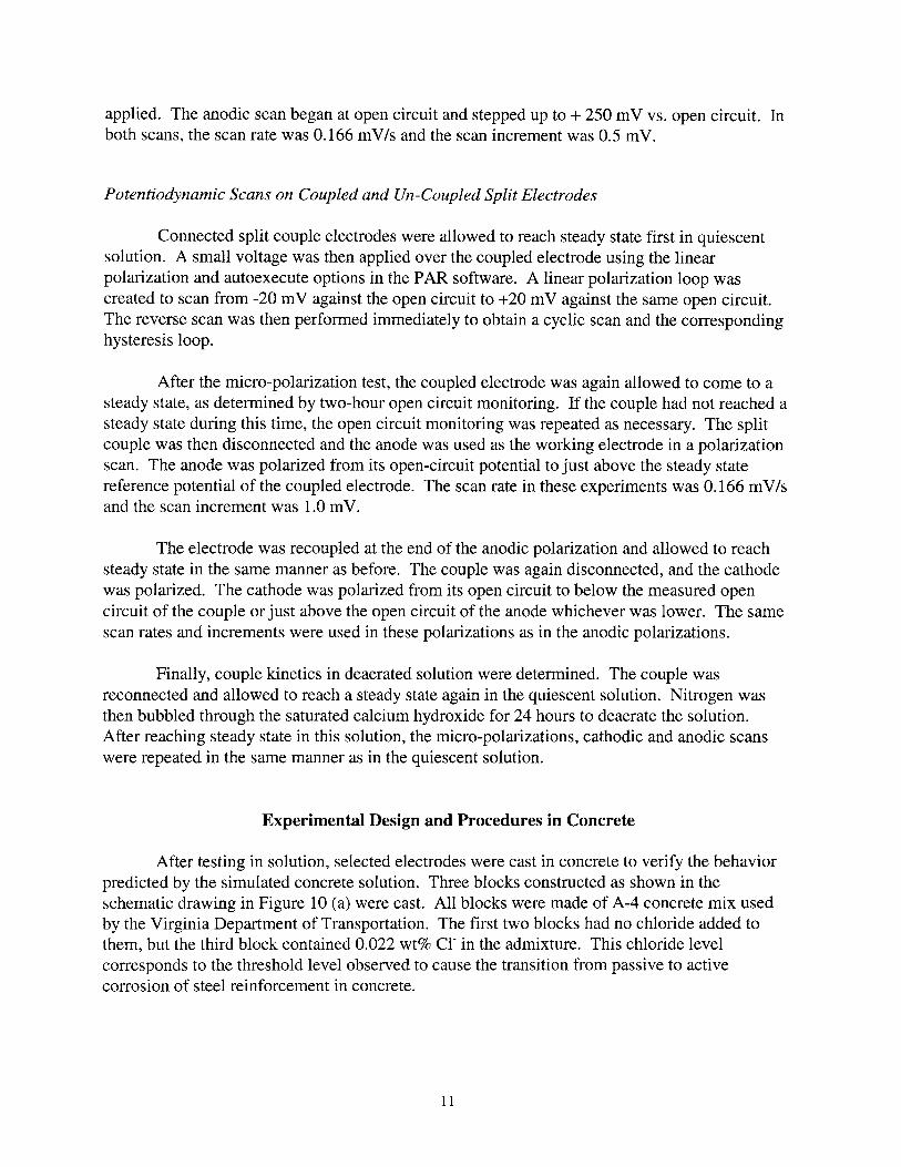
Experimental Design and Procedures in Concrete
After testing in solution, selected electrodes were cast in concrete to verify the behaviorpredicted by the simulated concrete solution. Three blocks constructed as shown in theschematic drawing in Figure 10 (a) were cast. All blocks were made of A-4 concrete mix usedby the Virginia Department of Transportation. The first two blocks had no chloride added tothem, but the third block contained 0.022 wt% cr in the admixture. This chloride levelcorresponds to the threshold level observed to cause the transition from passive to activecorrosion of steel reinforcement in concrete.
11
The electrodes were cast in the concrete as shown in Figure 10 (b). Each electrode was50 mm (2 in.) away from the other electrodes. Due to size limitations, the commercial Ag/AgCIelectrode was placed on its side along the bottom Gust above concrete cover) of the center of theblock. All other electrodes were 38 to 50 mm (1.5 to 2 in.) from the bottom.
After allowing the concrete to set in a temperature and moisture-controlled environmentfor one month, the various blocks were placed in water baths. The first two were placed indeionized water. The block containing admixed chloride was placed in 3.5 wt % NaCI solution.The electrodes and thermocouples were then connected to the data acquisition system. Two EXP1800 ™ boards from Keithley Metrabyte multiplexed the inputs to a DAS1802 HRTM boardwithin a computer. Labtech Notebook™ software was then used to control these boards and logthe collected data. Open circuit potentials and temperature data were collected every hour forone- week periods at a time to reach a total of at least 2000 hours.
RESULTS AND DISCUSSION
Behavior of Galvanic-Couple Electrodes in Simulated Concrete Solution
Electrode Stability Results
The galvanic couple electrodes have been categorized by couple half behavior. Theelectrode stabilities are discussed with regard to these categories in the following sections. Opencircuit potentials and standard deviations are discussed as well as couple potential control and thegalvanic series for calcium hydroxide.
A Galvanic Series for Saturated Calcium Hydroxide
Each galvanic couple electrode was designated as either noble-noble, noble-active, activeactive, or noble/active-passive metal pairs, according to the relative nobility of each component.To define the couple sets, an experimental galvanic series was obtained for saturated calciumhydroxide and is shown in Figure 11. Metals with higher open circuit potentials such as gold,silver, nickel, and copper were considered noble in this study. Molybdenum, tungsten, and leadwere the only active metals considered. Normally, tin and zinc have extremely active opencircuit potentials, but both exhibited passive behavior in the highly alkaline environment.
The galvanic series was then used to predict the anode and cathode in each couple. In thiswork, the couples have been designated as cathode-anode. For example, using this series, a AuCu couple would be classified as a noble-noble couple with a gold cathode and a copper anode.
Stability Behavior._The stability of the galvanic couples in saturated calcium hydroxidewas analyzed in terms of the standard deviations of the open circuit potentials versus time. All of
12
the data shown in this section pertain to couples with an anode and cathode of the same area. Tocompare data between separate tanks, the standard deviation of each couple was normalizedagainst the standard deviation of the commercial manganese dioxide reference electrode in eachrespective tank. Also, by normalizing the data, any temperature variations and SCE differencesbetween tanks can be minimized for direct comparison between all electrodes. Large standarddeviations can result from either gradual potential drift, potential steps, or noise of largeamplitudes. As long as the amplitude of the noise is low, the frequency is less important, and thefrequency of the noise can only be determined within the bounds of the frequency of datacollection. In this study, the open circuit potential behavior with time and the normalized andtrue standard deviations were all considered to account for the different forms of potentialvariations. Figures 12 (a), (b), and (c) show the distributions of the normalized standarddeviations for the three separate tanks of couples. The normalized standard deviations rangefrom less than 1 to 60 mV/mV. Several couples performed equivalently to or better than themanganese dioxide reference electrodes with actual standard deviations under 5-12 mV.
The wide variations in couple performance, allowed the electrodes to be classified assuccessful, promising, and unsuccessful. Those couples with normalized deviations less than themanganese standard were all considered successful, and couples with standard deviations greaterthan twice that of manganese dioxide were classified as unsuccessful. Electrodes between thesewere classified as promising couples. Table 2 (a), (b), and (c) give the mean potentials of thesuccessful, promising, and unsuccessful couples, respectively. These tables also list the true andrelative standard deviations of the couples.
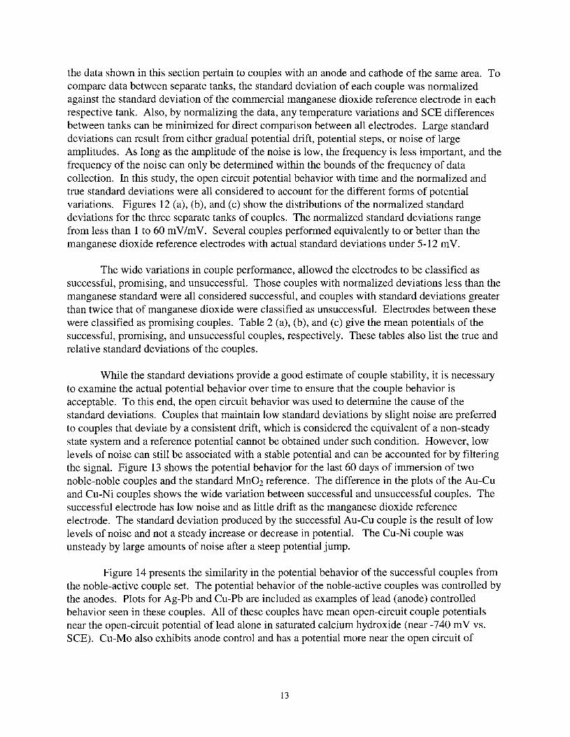
While the standard deviations provide a good estimate of couple stability, it is necessaryto examine the actual potential behavior over time to ensure that the couple behavior isacceptable. To this end, the open circuit behavior was used to determine the cause of thestandard deviations. Couples that maintain low standard deviations by slight noise are preferredto couples that deviate by a consistent drift, which is considered the equivalent of a non-steadystate system and a reference potential cannot be obtained under such condition. However, lowlevels of noise can still be associated with a stable potential and can be accounted for by filteringthe signal. Figure 13 shows the potential behavior for the last 60 days of immersion of twonoble-noble couples and the standard Mn02 reference. The difference in the plots of the Au-Cuand Cu-Ni couples shows the wide variation between successful and unsuccessful couples. Thesuccessful electrode has low noise and as little drift as the manganese dioxide referenceelectrode. The standard deviation produced by the successful Au-Cu couple is the result of lowlevels of noise and not a steady increase or decrease in potential. The Cu-Ni couple wasunsteady by large amounts of noise after a steep potential jump.
Figure 14 presents the similarity in the potential behavior of the successful couples fromthe noble-active couple set. The potential behavior of the noble-active couples was controlled bythe anodes. Plots for Ag-Pb and Cu-Pb are included as examples of lead (anode) controlledbehavior seen in these couples. All of these couples have mean open-circuit couple potentialsnear the open-circuit potential of lead alone in saturated calcium hydroxide (near -740 mV vs.SCE). Cu-Mo also exhibits anode control and has a potential more near the open circuit of
13
molybdenum than that of copper. While the Au-W couple is also controlled by the open-circuitpotential of the anode, it is inherently unstable by exhibiting potential drift.
Comparison of the plots of Cu-Mo and the lead couples provides a good example of theneed for normalizing standard deviations for data comparison between tanks. The Cu-Mo couplewas contained in Tank 2 while the lead couples were contained in Tank 1 and 3. The stabilitybehaviors of the manganese dioxide reference electrodes are included as a reference to tankbehavior and show an increase in the potential disturbances in Tank 2. Although the overallstability of the Cu-Mo couple appears to be less consistent than either of the lead couples, thetank behavior can be seen to be more erratic by the noise as seen in the manganese reference forTank 2.
Figure 15 provides similar information for noble/active-passive couples. As seen by thedata, the Pb-Sn couple was unsuccessful. This couple appears to be controlled more heavily bythe tin and does not have an open circuit potential near that of lead. The Pb-Zn couple, on theother hand, is another couple that is lead controlled, but lead is the cathode in this instance. TheAu-Sn couple is also cathode controlled by the gold. Finally, in Figure 16, stable and unstableactive-active couples are plotted. Both of these couples are under mixed control.
Couple Stability Control
In many of the successful couples, the respective couple behavior was influenced morestrongly by either the cathode or the anode. A summary of these couples is given in Table 3along with the couple potential. The strongest occurrence of this is seen in couples containinglead. The lead (usually the anode) controls the potential behavior of these couples and maintainsa reference potential that is very near its own open-circuit potential. The potential-controllingcomponent of couples such as these can playa strong role in determining the stability of thecouple as solution parameters are varied. A case in point, a couple that depends on the anodickinetics of one of its components may be more stable in deaerated solutions than a couple whosesteady state reference potential is strongly linked to cathodic control. Furthermore, by adjustingcathode to anode area ratios to maintain stable potential control, more stable or longer livedelectrodes may be developed.
Kinetics Results
DC electrochemical techniques were used to further test the viability of galvanic coupleelectrodes and to explain the observed open-circuit behaviors. The electrode stability was testedusing cyclic micro-polarizations and the results are detailed in the following sections. Mixedpotential theory has been employed to explain the open circuit behaviors of the couples.
Micro-Polarization Effects. Ideally, reference electrodes should polarize very little withthe application of small currents that might be passed in measuring electrical potentials. Aftersmall currents are applied, reliable reference electrodes should return to their reference potentials
14
almost immediately. In the case of corroding electrodes which are not in equilibrium, the mostsuccessful electrodes will be those that return to steady state quickly and do not shift far fromthat steady state during and after the application of small currents. From micro-polarization tests,these two parameters can be examined. Figure 17 shows a schematic micro-polarization for anideal reference electrode. Small slopes on these curves represent low polarizability.Furthermore, ideal reference electrodes show no hysteresis; the reference potential returnsimmediately to its original value after the current is no longer applied. For steady statereferences, larger hysteresis loops correspond to either slow return to steady state or failure toreturn to the original reference potential. Both of these conditions are generally unacceptable.The micro-polarizability slopes are shown in Table 4.
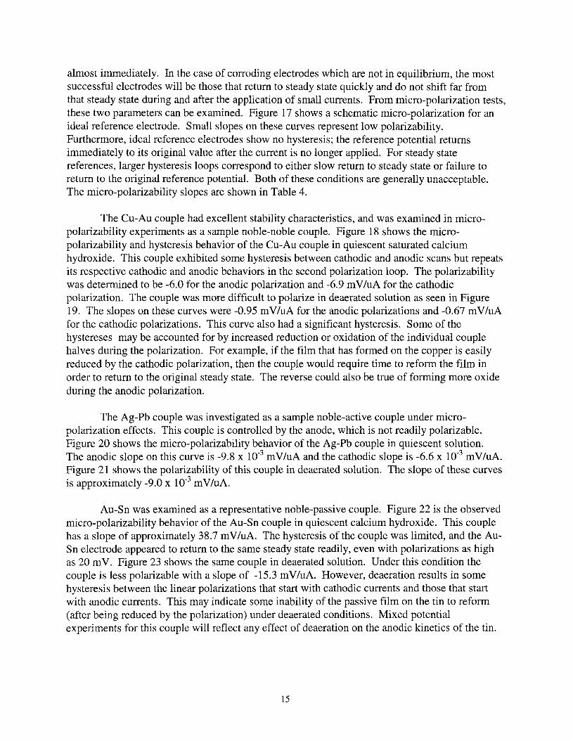
The Cu-Au couple had excellent stability characteristics, and was examined in micropolarizability experiments as a sample noble-noble couple. Figure 18 shows the micropolarizability and hysteresis behavior of the Cu-Au couple in quiescent saturated calciumhydroxide. This couple exhibited some hysteresis between cathodic and anodic scans but repeatsits respective cathodic and anodic behaviors in the second polarization loop. The polarizabilitywas determined to be -6.0 for the anodic polarization and -6.9 mV/uA for the cathodicpolarization. The couple was more difficult to polarize in deaerated solution as seen in Figure19. The slopes on these curves were -0.95 mV/uA for the anodic polarizations and -0.67 mV/uAfor the cathodic polarizations. This curve also had a significant hysteresis. Some of thehystereses may be accounted for by increased reduction or oxidation of the individual couplehalves during the polarization. For example, if the film that has formed on the copper is easilyreduced by the cathodic polarization, then the couple would require time to reform the film inorder to return to the original steady state. The reverse could also be true of forming more oxideduring the anodic polarization.
The Ag-Pb couple was investigated as a sample noble-active couple under micropolarization effects. This couple is controlled by the anode, which is not readily polarizable.Figure 20 shows the micro-polarizability behavior of the Ag-Pb couple in quiescent solution.The anodic slope on this curve is -9.8 x 10⁻³ mV/uA and the cathodic slope is -6.6 x 10⁻³ mV/uA.Figure 21 shows the polarizability of this couple in deaerated solution. The slope of these curvesis approximately -9.0 x 10⁻³ mV/uA.
Au-Sn was examined as a representative noble-passive couple. Figure 22 is the observedmicro-polarizability behavior of the Au-Sn couple in quiescent calcium hydroxide. This couplehas a slope of approximately 38.7 mV/uA. The hysteresis of the couple was limited, and the AuSn electrode appeared to return to the same steady state readily, even with polarizations as highas 20 mY. Figure 23 shows the same couple in deaerated solution. Under this condition thecouple is less polarizable with a slope of -15.3 mV/uA. However, deaeration results in somehysteresis between the linear polarizations that start with cathodic currents and those that startwith anodic currents. This may indicate some inability of the passive film on the tin to reform(after being reduced by the polarization) under deaerated conditions. Mixed potentialexperiments for this couple will reflect any effect of deaeration on the anodic kinetics of the tin.
15
Mixed Potential Results
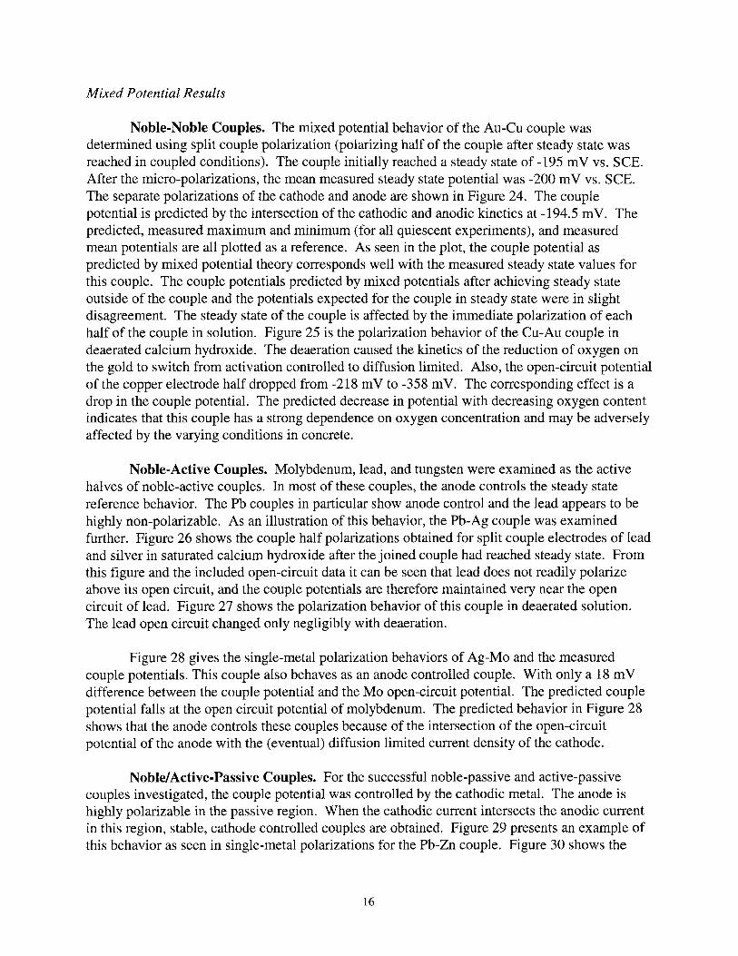
Noble-Noble Couples. The mixed potential behavior of the Au-Cu couple wasdetermined using split couple polarization (polarizing half of the couple after steady state wasreached in coupled conditions). The couple initially reached a steady state of -195 mV vs. SCE.After the micro-polarizations, the mean measured steady state potential was -200 mV vs. SCE.The separate polarizations of the cathode and anode are shown in Figure 24. The couplepotential is predicted by the intersection of the cathodic and anodic kinetics at -194.5 mV. Thepredicted, measured maximum and minimum (for all quiescent experiments), and measuredmean potentials are all plotted as a reference. As seen in the plot, the couple potential aspredicted by mixed potential theory corresponds well with the measured steady state values forthis couple. The couple potentials predicted by mixed potentials after achieving steady stateoutside of the couple and the potentials expected for the couple in steady state were in slightdisagreement. The steady state of the couple is affected by the immediate polarization of eachhalf of the couple in solution. Figure 25 is the polarization behavior of the Cu-Au couple indeaerated calcium hydroxide. The deaeration caused the kinetics of the reduction of oxygen onthe gold to switch from activation controlled to diffusion limited. Also, the open-circuit potentialof the copper electrode half dropped from -218 mV to -358mV. The corresponding effect is adrop in the couple potential. The predicted decrease in potential with decreasing oxygen contentindicates that this couple has a strong dependence on oxygen concentration and may be adverselyaffected by the varying conditions in concrete.
Noble-Active Couples. Molybdenum, lead, and tungsten were examined as the activehalves of noble-active couples. In most of these couples, the anode controls the steady statereference behavior. The Pb couples in particular show anode control and the lead appears to behighly non-polarizable. As an illustration of this behavior, the Pb-Ag couple was examinedfurther. Figure 26 shows the couple half polarizations obtained for split couple electrodes of leadand silver in saturated calcium hydroxide after the joined couple had reached steady state. Fromthis figure and the included open-circuit data it can be seen that lead does not readily polarizeabove its open circuit, and the couple potentials are therefore maintained very near the opencircuit of lead. Figure 27 shows the polarization behavior of this couple in deaerated solution.The lead open circuit changed only negligibly with deaeration.
Figure 28 gives the single-metal polarization behaviors of Ag-Mo and the measuredcouple potentials. This couple also behaves as an anode controlled couple. With only a 18 mVdifference between the couple potential and the Mo open-circuit potential. The predicted couplepotential falls at the open circuit potential of molybdenum. The predicted behavior in Figure 28shows that the anode controls these couples because of the intersection of the open-circuitpotential of the anode with the (eventual) diffusion limited current density of the cathode.
Noble/Active-Passive Couples. For the successful noble-passive and active-passivecouples investigated, the couple potential was controlled by the cathodic metal. The anode ishighly polarizable in the passive region. When the cathodic current intersects the anodic currentin this region, stable, cathode controlled couples are obtained. Figure 29 presents an example ofthis behavior as seen in single-metal polarizations for the Pb-Zn couple. Figure 30 shows the
16

polarization behavior of the Au-Sn couple, after a steady state couple potential has been reached.This couple behavior is dependent on a non-polarizable cathode to maintain stability as thesolution parameters change. Figure 31 shows the deaerated split couple mixed-potential behaviorof the Au-Sn couple. As can be seen by comparing Figures 30 and 31, the cathodic kinetics andopen-circuit potential of gold are dependent on the oxygen content of the solution. The extremechange in the gold behavior can push the couple potential into a less stable region of the anodiccurve, and results in a large drop in couple potential.
Effects ofArea Ratio on Stability
Stability behavior was determined for three area ratios of a subset of the original couples.Table 5 gives the mean open-circuit potentials of the couples, the true standard deviations, andthe normalized standard deviations at cathode-to-anode area ratios of 10: 1, 1: 1, and 1: 10. Plotsof the couple potentials versus time for all three area-ratios are also given for several couples.Figure 32 is the couple potential versus time data for the Au-Cu and couple. Figure 33 shows thedata obtained for the Ag-Ni couple. Both of these are noble-noble couples, but the Ag-Ni couplewas strongly affected by area ratio, whereas the Cu-Au couple remained at relatively the samestability. Figures 34 and 35 show the potential stability against time for noble-active couples,Ag-Mo and Cu-Mo, respectively. Noble-active couples tended to gain stability when the anodearea, which controls the couple potential, was increased. Finally, Figure 36 gives the potentialstability of active-active couple Mo-W at different area ratios.
The predicted effect of varying area ratios was plotted for five different couples (fromthree different sets of couples): Au-Cu (noble-noble), Ag-Mo, Cu-Mo, Ni-W (noble-active), andMo-W (active-active). Figure 37 shows the predicted and observed noble-noble behavior. Thepredicted area ratio effects were found with split couple metal samples, and the area ratios wereadjusted mathematically from the original data (multiplied by ten).
The area effect on the couple potentials follows the trend of mixed potential theory, inthat a larger cathode would draw the couple potential toward more noble values. Similarly, alarger anode tended to pull the couple potential in the active direction. The open-circuit potentialversus time plots show that the area ratios can be critical to the life of the couples. Couples likeCu-Mo and Ag-Mo become more noble, in a step function, when the cathode is much larger thanthe anode. One possible explanation for the step is an increase in the corrosion rate andsubsequent decrease in area of the anode. Failure of the anode would result in a shift to morenoble couple potentials with an upper limit at the single-metal open-circuit potential of thecathode.
A Final Note on Galvanic-Couple Electrode Behavior
As seen by comparing the stability, area, and mixed potential data, not all of the metalliccouplings are consistent between different electrodes (of the same type). In other words, twoseparate Au-Cu couples may reach different steady state potentials. Table 6 illustrates this point
17
for several couples by comparing the open-circuit behaviors of two electrodes of the same typeused in different tests. The inconsistency between electrodes may be a problem of constructionpractices, and preconditioning may reduce this inconsistency. Additional testing should be doneto determine the best construction for each couple and any required conditioning treatments.
Finally, the mixed potential theory provides a means of selecting couples for furtherinvestigation. For example, it was determined that all of the active metals tend to control thecouples and are highly non-polarizable. The passive metals were found to have excellentstability behavior when coupled to cathodes that controlled the couple and were within the rangeof passivity of the metal. These two types of behavior suggest that active, non-polarizable metalsand passive metals would combine to make stable, low hysteresis couples. Mo-Sn and Pb-Zncouples are two examples of this combination, which performed relatively well in stability tests.Further testing on these couples is recommended.
Behavior of Galvanic-Couple Electrodes in Concrete
Electrode Stability in Plain Concrete
A test set of twelve successful and unsuccessful galvanic couple electrode types wereembedded in concrete to obtain stability and couple potential data. The stability of these couplesis discussed in the following sections, specifically with respect to the behavior of twocommercial electrodes in the same concrete system.
Commercial Reference Electrodes
The reference potentials of two commercial embeddable reference electrodes weremonitored along with the potential behaviors of the galvanic couples in concrete. The potentialsof a sse electrode and a manganese dioxide reference electrode were measured against acommon manganese dioxide reference electrode. As in saturated calcium hydroxide, thestandard deviations of the potentials were obtained and are presented for these electrodes inTable 7. First, the mean potentials and standard deviations for the Mn02 and the sse electrode,against the Mn02 (common), are presented. Then the potential of the sse against the first Mn02electrode is then presented. This potential is given to determine any errors specific to oneelectrode. The potentials of these electrodes are plotted with respect to time in Figure 38. Thebehavior of the sse can be compared to that of Mn02 through this graph by assuming constantMn02 (common) behavior. The relative behavior of the two manganese electrodes to oneanother can be compared through the sse by assuming that the sse is a consistent electrode.This figure shows the consistency between the two manganese reference electrodes, and similarstable behavior for all three electrodes. All of the electrodes had standard deviations that werevery close. The behavior of these electrodes agreed with behaviors seen by other researchers.
18
Galvanic-Couple Electrodes
The stability behavior of the galvanic-couple electrodes in concrete was measured againstthe common manganese dioxide reference electrode. Then, this stability behavior is compared tothat observed in saturated calcium hydroxide to determine the applicability of the behaviorobserved in simulated concrete solution. The potentials and standard deviations of the test set forboth solution and concrete are presented in Table 8.
Although the values for the embedded situation in Table 8 were measured against amanganese reference, the potentials have been reported against SCE to simplify comparisons.Also, Figure 39 shows the ranking of the couples by their standard deviations. The bar plotshows that the stability of the couples in concrete varied from 5 mV to 300 mV. The last sixgalvanic couple electrodes in this plot had standard deviations greater than twice that of themanganese reference, but the other six had standard deviations under 12 mY. The Pb-Zn coupleperformed better than the manganese standard.
The open-circuit behavior of these electrodes was examined against time to determine thecauses of the standard deviation (noise or drift). In the following sections, the electrodebehaviors are discussed in reference to each class of couples.
Noble-Noble Electrodes. In Figure 41, the couple potential vs. time is plotted for thetwo noble-noble couples, Au-Cu and Cu-Ni. In simulated concrete solution, the Au-Cu couplewas extremely stable and the Ni-Cu couple was unstable. In concrete, however, the particularAu-Cu couple that was monitored was unstable by noise. Large potential spikes characterize thebehavior of this couple. The standard SSC behavior has been included in this plot and themagnitude of the noise spikes shown by the Au-Cu electrode were appreciable in comparison tothe behavior of the standard. In contrast, the Ni-Cu couple was reasonably stable with a standarddeviation under 10mV, which is slightly less than twice that of the commercial standards.
Noble-Active and Active-Active Couples. Many noble-active couples were embeddedto examine the behavior of different anodes within this couple type. As determined earlier insaturated calcium hydroxide, noble-active couples were anode-controlled. Therefore, differentanode metals were examined in the embedded situation for similar cathodic elements. Figure 41shows the couple potentials versus time for the noble-active couples containing lead and theactive-active Mo-Pb couple in which lead and molybdenum had mixed control. Recall that of theCu-Pb, Ag-Pb, and Mo-Pb couples, only the Mo-Pb couple was unsuccessful in calciumhydroxide. In the embedded environment, the opposite appears to be true. The Mo-Pb coupleappears to have gained stability, but is no longer in a region of mixed lead and molybdenumcontrol. The couple potential of this electrode is not near any predicted lead potential. On theother hand, the Ag-Pb and Cu-Pb couples that had been stable in solution were unstable inconcrete. These two couples both exhibited reasonable stability that was interrupted by apotential step from approximately -880 mV to -360 mV (vs. Mn02). The potential step is thenfollowed by reasonable stability. The similar potential behavior of these couples indicatescontinued control by the lead half of the couple. Had the couples failed completely, it is notlikely that their potential ranges would be so close together or so low. The predicted open circuit
19
behaviors of silver and copper in solution are -271 mV and -376 mV vs. Mn02, respectively.However, other copper controlled couples (such as Cu-Zn and Au-Cu) had much higher couplepotentials. One possible explanation for the step change in couple potential is a change in theoxidation state of lead from PbO to Pb30 4. Furthermore, the decay of the lead half by anodicdissolution would have resulted in gradual potential drift and not a sudden step.
Figure 42 shows the couple potential behavior of two noble-active couples containingmolybdenum, Mo-Ag and Mo-Cu. The Mo-Pb couple is also included on this graph to show thecontrol of molybdenum in this active-active couple. By comparing couple potentials, it can beseen that all of the molybdenum couples were behaving under molybdenum control. The meanstable couple potential is approximately -650 mV vs. Mn02 for all three couples. The Mo-Pband Mo-Ag couple remained stable throughout the 2000-hour experiment. The Cu-Mo couple,on the other hand, lost stability after 1000 hours, and the potential jumped from molybdenumcontrol up to 8.8 mV vs. Mn02. The Ag-Mo and Mo-Pb couples were considered only promisingand unsuccessful, respectively, in solution; but the Cu-Mo couple had been successful insolution.
The two couples under tungsten control that were investigated in concrete had highstabilities. Figure 43 shows the couple potential behavior for tungsten controlled Cu-W and NiW couples. In solution, the Cu-W couple was unsuccessful, and the Ni-W couple wassuccessful. As with the noble-noble couples, the noble-active electrodes behaved somewhatdifferently in concrete than in the saturated calcium hydroxide solution. Initially, it waspostulated that unstable electrodes in solution would generally be unstable in concrete as well.However, it has been shown that this is not necessarily the case and the electrode behavior mustbe examined in the concrete environment to determine the true embedded performance of theelectrode.
Noble/Active-Passive Electrodes. Noble-passive and active-passive couples containingzinc and tin as the passive metals and various cathodic halves were embedded. The couplepotential behavior with time is plotted for these couples in Figure 46. The Pb-Zn couplestabilized to the couple potential predicted by the calcium hydroxide experiments. The cathodecontrols the potential in this couple and it appears to be stable in both simulated concrete solutionand in concrete. The Au-Sn and Cu-Zn couples also were cathode controlled; but neither of thesecouples remained stable. The Au-Sn shows slow breakdown of the high potential (within thepassive region of the Sn), resulting in breakdown of the couple potential to the active region ofSn. While this couple had been stable in simulated concrete solution, the actual concretebehavior was unstable after 1000 hours. This couple may easily benefit by adjusting the cathodeto anode area ratios to maintain a stable (passive) potential on the Sn. Cu-Zn exhibited unstablebehavior in both environments, and as seen in Figure 45, the breakdown of the couple wascaused by the polarization to a much more noble potential. The couple potential stepped up to9.7 mV vs. Mn02 (174.7 vs. SCE). This indicates that the couple is no longer held in steady stateby the passive metal (the passivity may have broken down into dissolution), but rather iscompletely cathodically controlled and therefore unstable.
20
Electrode Stability in Chloride Contaminated Concrete
The same set of electrodes was embedded in chloride contaminated concrete blocks. Thestability behaviors of these galvanic-couple electrodes and the commercial references electrodesare discussed in the following sections in terms of electrode classes.
Commercial Reference Electrodes
The reference potentials of commercial Ag/AgCI and manganese dioxide electrodes weremeasured against a second commercial manganese dioxide reference to obtain potential behaviorof standard electrodes in a chloride concrete environment. Table 9 shows the reference potentialsfor these electrodes in both concrete environments. Figure 45 shows the potential behavior over1000 hours for both electrodes in the chloride system. Recall that the commercial sse electrodeis contained in a chloride-rich backfill, and therefore is relatively unaffected by the change inchloride content of the concrete.
Galvanic Couple Electrodes
The galvanic couple behaviors over the first 1000 hours in a chloride-containing concreteenvironment were as a whole similar to that seen in plain concrete with a few exceptions. Figure46 shows the observed standard deviations for the potentials of all of the couples. The meanmeasured couple potentials and standard deviations are shown in Table 10. By comparingpotential values in Table 10 and Table 8, it can be seen that many successful couples had highstandard deviations, but not always too high enough to make them unsuccessful. On the otherhand, several couples such as Au-Cu, Pb-Ag, Cu-Pb, Cu-Mo, Cu-Zn, and Au-Sn became morestable. Only five couples in this environment had standard deviations less than twice that of themanganese reference.
Noble-Noble Electrodes. The behavior of the noble-noble couples improved in thechloride and concrete environment. As seen by the standard deviations in Figure 46, the Cu-Nicouple is stable under these conditions as well, and the Au-Cu couple is more stable in thisenvironment. The stability of these two couples can be seen in the open circuit behavior shownin Figure 47. The Au-Cu couple shows distinct improvement from the previous environment.However, the couple behaviors for this electrode were seen to vary from one Au-Cu couple to thenext in calcium hydroxide solution, and the improvement in stability may be related more to thedifference in the couples and not the difference in environment. The noise in both couples isslightly larger than before, but the overall standard deviation was within the bounds of stability.One theory that might explain this phenomenon is the increase in noise may be related to theincrease in conductivity of the solution. The increased conductivity may lead to increasedelectrode sensitivity because of increased ionic transfer between the electrode halves.
Noble-Active Electrodes. As before, the noble-active couple behaviors have beenexamined for specific characteristics of electrodes with the same anode and various cathodic
21

elements. The couple potential behaviors of the lead controlled couples are shown in Figure 48.In chloride concrete, the lead couples display the same behavior seen in plain concrete. The AgPb and Cu-Pb couples are unstable by a step in potential, but in the chloride environment the stepoccurs at an earlier time. The Mo-Pb couple does not exhibit this step behavior and is presumedto be controlled by the molybdenum as in plain concrete. The standard deviation of this couple iscaused by the noise level, but in the chloride environment, the noise spikes are much greater thanthe previous potential disturbances. The behaviors of molybdenum controlled couples wereexamined in this environment and are shown in Figure 49. The Ag-Mo and Mo-Pb couples werenot as noise resistant in the chloride environment. All of the molybdenum couples have large(-100 mY) noise spikes. The Cu-Mo couple again exhibits the most erratic behavior. Finally,the tungsten couples are shown in Figure 50. The tungsten-controlled couples had slightly highernoise levels in the chloride environment, but the potential behavior of these couples wasgenerally stable. Both Ni-W and Cu-W ranked among the best couples in the chlorideenvironment.
Noble/Active-Passive Electrodes. The noble-passive and active-passive couples thatrely on large regions of passivity to maintain stable couple potentials are potentially the mostvulnerable to the chloride environment. Pb-Zn, Au-Sn, and Cu-Zn couples were investigated forthis effect. The potential behavior of these couples with time is shown in Figure 51. The Pb-Zncouple was strongly affected by the chloride addition. Compared this with the couple's behaviorin plain concrete (Figure 44), it can be seen that the Pb-Zn couple breaks down both by potentialdrift (initial drop) and by the potential spikes that have been characteristic of lead. On the otherhand, the Au-Sn and Cu-Zn couples are more stable in the chloride environment. The Cu-Zncouple while more stable in this environment, is still unacceptable, because of the small upwardpotential drift. The Au-Sn couple stability behavior was successful, but should be monitored forlonger periods of time to determine the lifetime of the couple. The Au-Sn couple in Figure 44,for chloride free concrete, did not show signs of instability until after the period of timemonitored for the chloride environment.
SUMMARY AND CONCLUSIONS
The main objective of this work was to determine the feasibility of using galvanic couplesas stable permanent reference electrodes in concrete environment. To this end, the performancein saturated calcium hydroxide (for simulating concrete-pore solution) and later in concrete (withand without chloride admixed) of several candidate electrodes were investigated. Theinvestigation has clearly demonstrated the viability of this new concept, within an acceptablepotential deviation, for several different couples in both simulated concrete and real concreteenvironments for over 2000 hours. Galvanic couples that exhibited stable behavior in bothenvironments include the Ni-W, Pb-Zn, and the Ag-Mo couples. However, in concrete withoutand with chloride present, only the tungsten couples were successful. Several other couplesincluding Au-Sn and Au-Cu were successful in the chloride-contaminated concrete but not in thechloride-free concrete, or vice versa.
22
The controlling half of each couple was determined by the location of the couple potentialrelative to the open circuit potentials of its anode and cathode. In solution, noble-active coupleswere controlled by the anode. Generally, the anode in these couples is highly non-polarizableand the cathode is polarized down to the anodic potential. The couple potential in noble or activeand passive couples was determined by the cathodic behavior. In these couples, the highlypolarizable anode is held at a steady state within its passive region. No clear trend controls eitherthe successful noble-noble or active-active couples. Mixed potential theory was used to showand explain the potential based control mechanisms. The couple behavior seen in concretetended to follow these guidelines for anodic or cathodic control. However, in some cases, whilethe steady state potential was controlled by the same mechanism for the couple in concrete as insolution, the polarization behavior of the couple halves resulted in either gained or lost stability.
The noble-active couples containing lead were all lead controlled in saturated calciumhydroxide. Similarly, with the exception of Mo-Pb, all lead couples in concrete were also leadcontrolled. However, these electrodes behaved differently in solution and in concrete, evenwithin the control of the lead. The couple potential is stable in concrete on either side of apotential step. All of the noble-active type of electrodes that contain lead have the same potentialinitially, and at different times their potentials step to a common value of -360 mV vs. Mn02.Because the couples all exhibit the same potentials on either side of the step, it is theorized thatthis step is a function of the oxidation state of lead, and that lead continues to control the couplesafter the step. Because the couples reach a new steady state, if the step could be forced to occurbefore the couple is embedded, these electrodes could still be used as pseudo referenceelectrodes. The potential step exhibited by these electrodes in the chloride environment occurs atearlier times.
Noble-Noble couples are very stable on an individual basis. However, these electrodesare not very reproducible between electrodes of the same material. In solution, the Au-Cuelectrode was consistently stable, but the steady state reference potential varied for differentelectrodes by more than the standard deviation. The Cu-Au electrode in plain concrete was notstable, but the same electrode was stable in concrete with chloride. The chloride may have madethe electrode more stable by increasing the conductivity of the environment, but without furthertesting there is no way of knowing if this effect is caused by the chloride or only the differencesin the two Cu-Au electrodes.
Noble-passive and active-passive electrodes were stable in both solution and concreteenvironments when the cathodic element was extremely stable. The Pb-Zn and Au-Sn coupleswere stable in solution; the Au and Pb had stable kinetics. On the other hand, the Au does notmaintain the potential within stable passivity in concrete. The Pb-Zn couple is more stable inconcrete. It relies on the cathodic kinetics of the lead for stability, and does not have thepotential step seen in lead anodic controlled couples. However, because these couples rely onpassivity for stable steady state reference potentials, the introduction of chloride into theenvironment causes instabilities.
Finally, based on the potential control seen in both concrete and solution environments,it is probable that the stability and/or lifetime of these electrodes could be increased by adjusting
23
area ratios. As demonstrated in solution experiments, all of the noble-active couples becamemore stable with increased anodes relative to the cathode size.
RECOMMENDATIONS
To facilitate eventual development of a viable, concrete-embeddable galvanic-couplereference electrode, it is recommended that the following be investigated: (a) the effect of theconcrete environment (pH, oxygen, and chloride content) on the behavior of this type ofelectrodes, and (b) optimization of electrode characteristics (stability and service life) by varyingthe anode-to-cathode area ratio and the geometry of the electrodes. This final developmentaleffort should be limited to a few particularly promising candidate electrodes that could bedesigned to provide optimum characteristics, specifically the Cu-W, Ni-W, and Cu-Ni couples.Since tungsten is often used as a component of thermocouples and the tungsten couples mayexhibit shift in potential with temperature, these electrodes should also be monitored fortemperature variations.
REFERENCES
1. Dehghanian, C., Root, C. R., and Locke, C. E. Review ofEmbeddable Reference Electrodesfor Portland Cement Concrete. Corrosion/81 paper no. 45, National Association ofCorrosion Engineers, Houston, Texas, 1981.
2. Bennett, J.E. and Mitchel, T. A. Reference Electrodesfor Use with Reinforced ConcreteStructures. Corrosionl92 paper no. 191 , National Association of Corrosion Engineers,Houston, Texas, 1992.
3. Ives, D. J. G. and Janz, G. J. Reference Electrodes Theory and Practice, Academic Press,Inc., New York, 1961.
4. Ansuini, F. J. and Dimond, J. R. Long Term Stability Testing ofReference Electrodes forReinforced Concrete. Corrosionl94 paper no. 295, Houston: NACE 1994.
5. Arup, H. and Sorensen, B. A New Embeddable Reference Electrodefor Use in Concrete.Corrosionl92 paper no. 208, National Association of Corrosion Engineers, Houston, Texas,1992.
6. Schell, H. C., Manning, D. G., and Pianca, F. Embedded Reference Cells for use inCathodically Protected Concrete. Transportation Research Record 1211, p. 60-71,Washington, D.C., 1989.
24
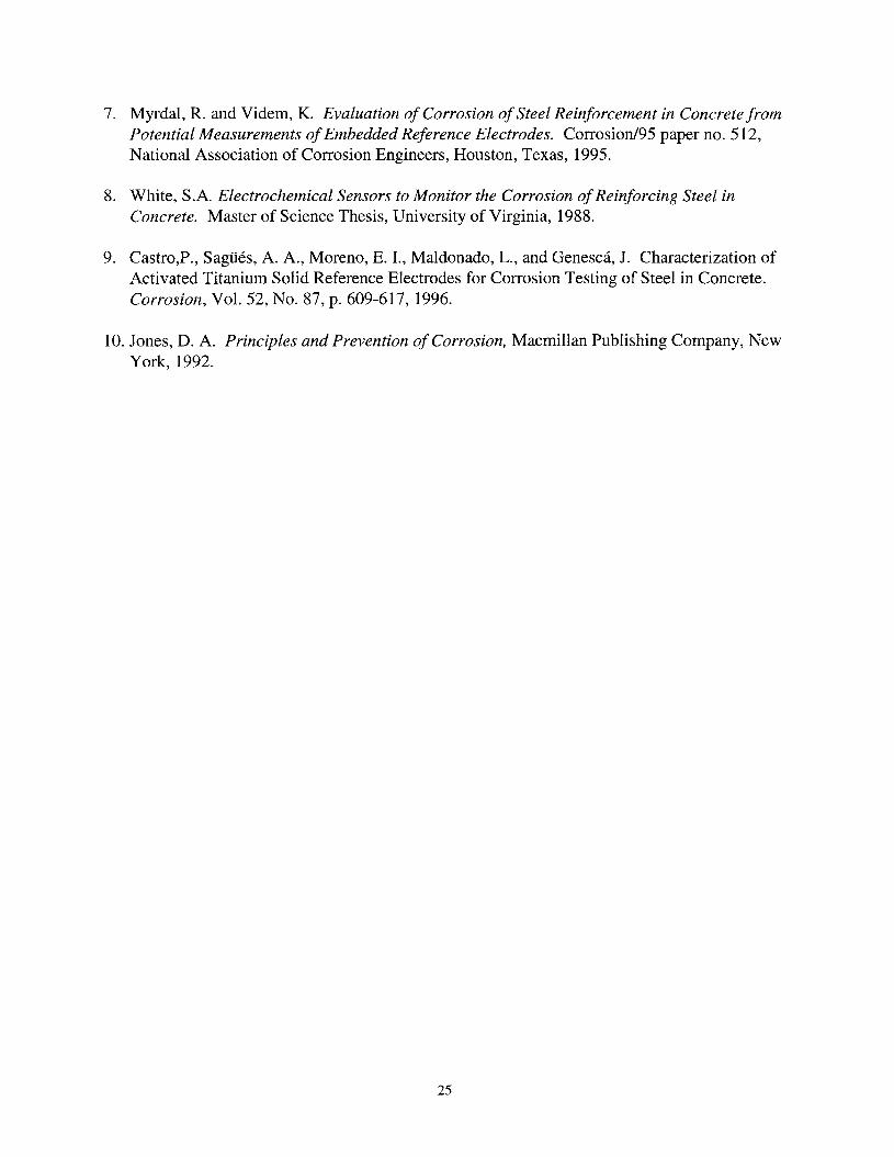
7. Myrdal, R. and Videm, K. Evaluation of Corrosion ofSteel Reinforcement in Concrete fromPotential Measurements ofEmbedded Reference Electrodes. Corrosion/95 paper no. 512,National Association of Corrosion Engineers, Houston, Texas, 1995.
8. White, S.A. Electrochemical Sensors to Monitor the Corrosion ofReinforcing Steel inConcrete. Master of Science Thesis, University of Virginia, 1988.
9. Castro,P., Sagiies, A. A., Moreno, E. I., Maldonado, L., and Genesca, J. Characterization ofActivated Titanium Solid Reference Electrodes for Corrosion Testing of Steel in Concrete.Corrosion, Vol. 52, No. 87, p. 609-617, 1996.
10. Jones, D. A. Principles and Prevention of Corrosion, Macmillan Publishing Company, NewYork, 1992.
25


FIGURES

Electrical Lea&-
Cotton Bag--IProprietary Backfill
AgWirewith AgCICoating
KCI Gel
Figure 1. The structure of an embeddable silver-silver chloride electrode.
Polymer Casing
Mortar Tip-DiffusionBarrier
NaOH Gel--
Electrical Lead
Metal Cap
--Manganese Dioxide/Manganese Trioxide
Figure 2. The structure of a Mn02/Mn203 embeddable reference electrode.
Soldered ConnectionBetween Wire AndBrass Fitting
Epoxy Plug
Electrical Lead
Ozite Sealant
Figure 3. The structure of a graphite pseudo reference electrode.

+
t10 (M)H2
(N)Hz
Ecnuple
~x
/1~
10 (M)
ICOIT' (M)
~x
~/f
10 (N)
~ Total AnodicCurrent
~Icouple
~ Total CathodicCurrent
ICOIT )
log Current
Figure 4. A schematic Evans diagram of a galvanic couple for metals M and N.
4cm x 0.5 mm diam. wire
Pb/SnSolder
r Polymer Coating
----~--------An0de
\~--~~~-.......------Cathode
0.2 cmdiam.Insulated Copper Wire
Figure 5. A schematic of the structure of an embeddable galvanic couple referenceelectrode.
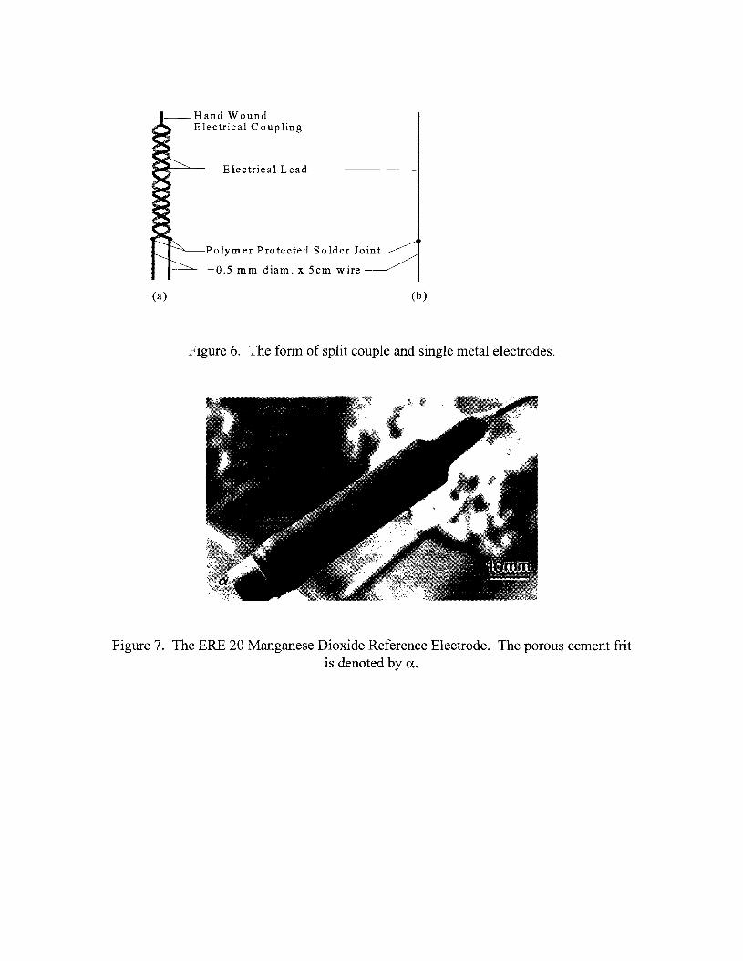
--Hand WoundElectrical Coupling
Electrical Lead
Polymer Protected Solder Joint
--------"'---0.5 mm diam. x 5cm wire
(a) (b)
Figure 6. The form of split couple and single metal electrodes.
Figure 7. The ERE 20 Manganese Dioxide Reference Electrode. The porous cement fritis denoted by u.
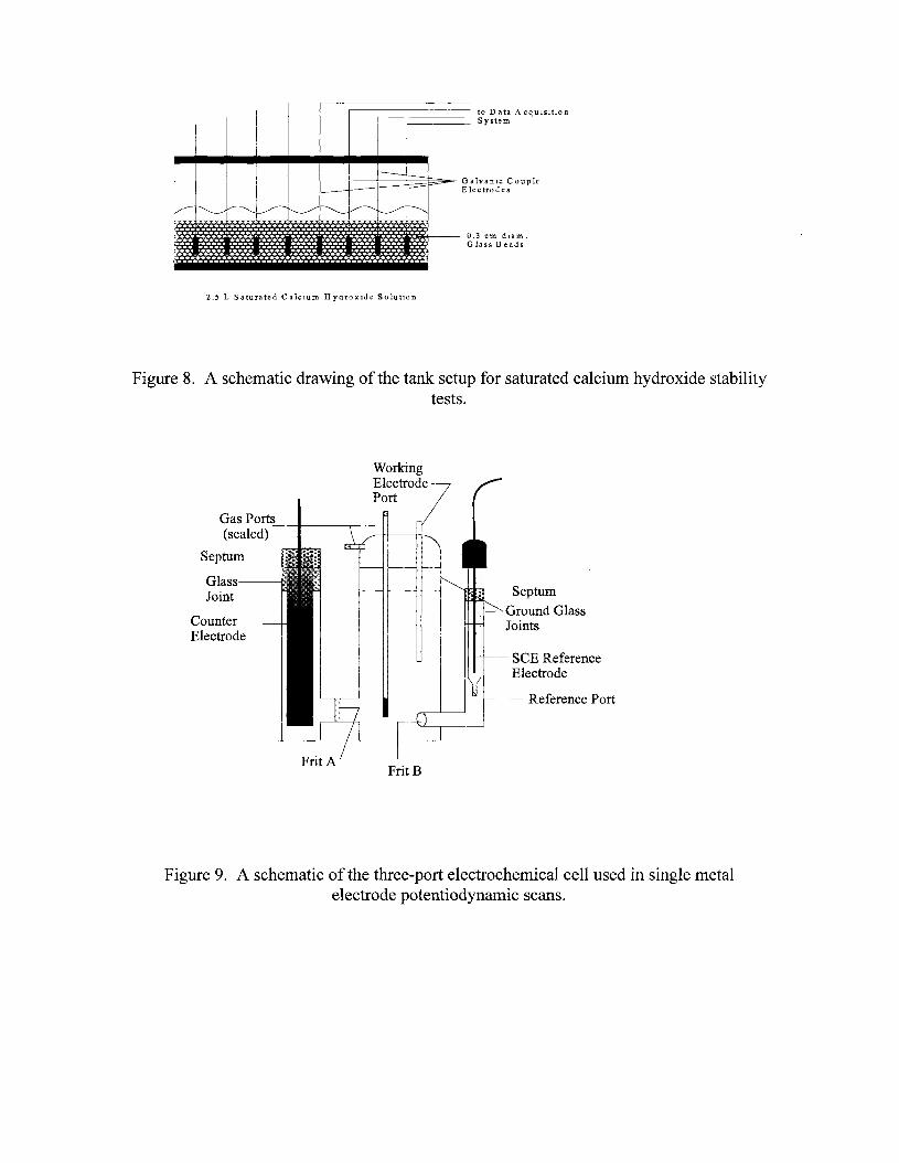
to 0 ata A cquIsItlOnSystem
alvanIC Coupleectro de s
.3 cm dlam.Glass Beads
------===-====-' GI-I---- EI
~~~
---------~I'---~~ ---........
0
2.5 L Saturated CalcIUm HydroxIde SolutIon
Figure 8. A schematic drawing of the tank setup for saturated calcium hydroxide stabilitytests.
WorkingElectrodePort
Gas Ports ------.--------j.
(sealed)
Septum
Glass---n
Joint
CounterElectrode
FritB
"""~ ;1--- Septum
Ground GlassJoints
seE ReferenceElectrode
Reference Port
Figure 9. A schematic of the three-port electrochemical cell used in single metalelectrode potentiodynamic scans.
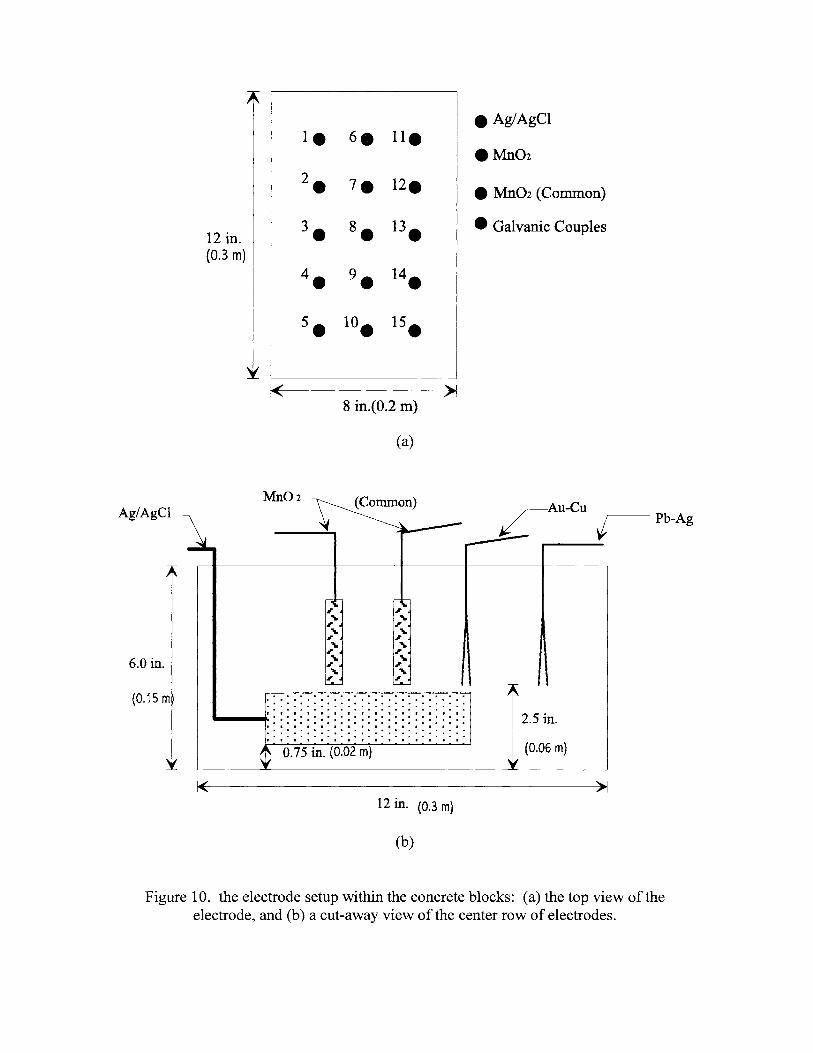
e Ag/AgCIIe
6_lIe
.Mn022. 7e 12e e Mn02 (Common)
12 in. 3. 8. 13. e Galvanic Couples
(0.3 m)
4. 9. 14.
5. 10. 15.
1<8 in.(O.2 m)
>1
(a)
Ag/AgClMn02 (Common)
Pb-Ag
0.75 in. (0.02 m)
· .. . . . . . . . . . . . . . .· .. . . . . . . . . . . . . . .· .--....::::::::::::::::::::::::::::::(0.06 m)
2.5 in.
,...,...,...,...,...,
."...
."...
."...
."
"."
"."
(0.15 m
6.0 in.
1< >112 in. (0.3 m)
(b)
Figure 10. the electrode setup within the concrete blocks: (a) the top view of theelectrode, and (b) a cut-away view of the center row of electrodes.
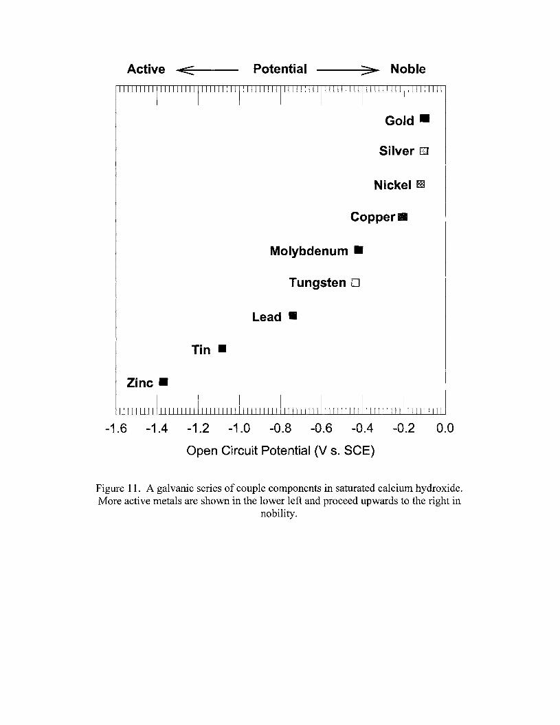
Active .....c:::::~--- Potential ---:::::>~ Noble
Gold --
Silver OJ
Nickel iii
Copper III
Molybdenum II
Tungsten D
Lead II
Tin II
Zinc II
-1.6 -1.4 -1.2 -1.0 -0.8 -0.6 -0.4 -0.2 0.0
Open Circuit Potential (V s. SCE)
Figure 11. A galvanic series of couple components in saturated calcium hydroxide.More active metals are shown in the lower left and proceed upwards to the right in
nobility.
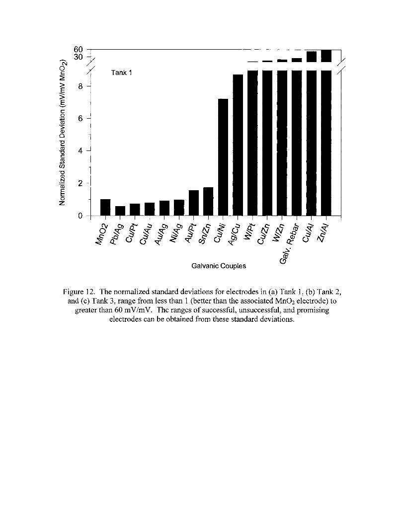
60 )/30Noc:~
> 8E>E
'-"'"c:a
+:icoos>(])
oEco
"'Cc:coen"C(])
o~
mEL-aZ
6
4
2
o
Tank 1
Galvanic Couples
----1111}
Figure 12. The normalized standard deviations for electrodes in (a) Tank 1, (b) Tank 2,and (c) Tank 3, range from less than 1 (better than the associated Mn02 electrode) to
greater than 60 mV1mV. The ranges of successful, unsuccessful, and promisingelectrodes can be obtained from these standard deviations.
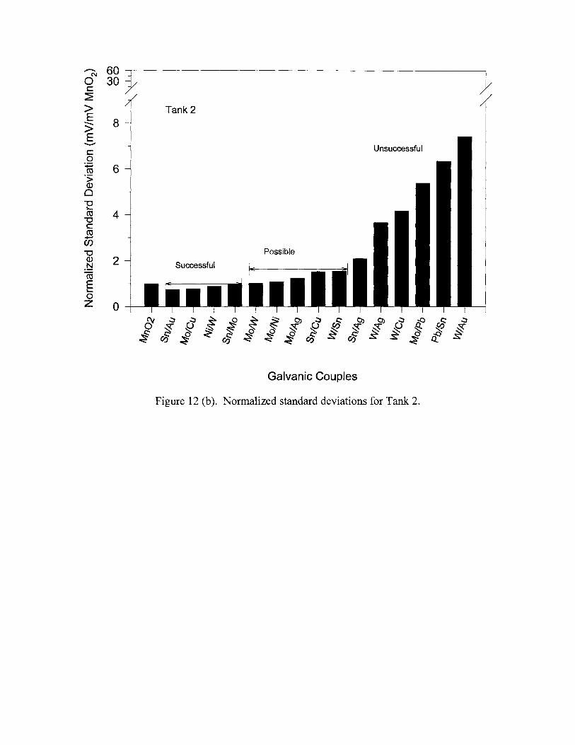
...............N
oc:~
>E>;E
"'-""
c:a+:iroos;Q)
o-ero
"'Cc:ro......en
"'CQ)
o~roEL-
aZ
60 )/30
8
6
4
2
o
Tank 2
Unsuccessful
Possible
Successful
Galvanic Couples
Figure 12 (b)o Normalized standard deviations for Tank 2.
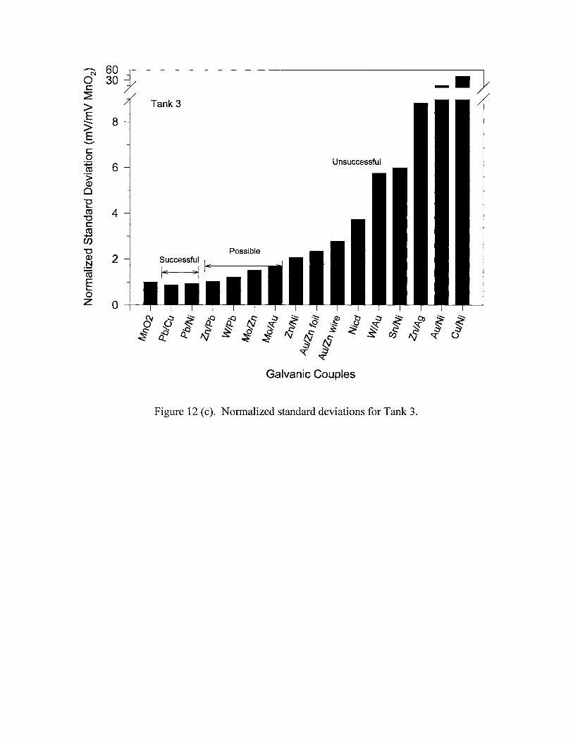
~
Noc:~
>E3>E
'-""
c:o
+:iro.s;Q)
o"'Cs...ro
"'Cc:ro
+-I
en"'CQ)
.~roEs...oZ
60 J/30
8
6
4
2
o
Tank 3
Unsuccessful
PossibleSuccessfulIE ~--
Figure 12 (c). Normalized standard deviations for Tank 3.
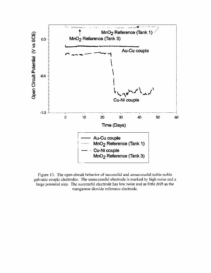
i"H" ~jt\(i(i(»>i<"'>j"4";i>;"<,>" », "",,~, ~"":'»' "'< ,,/,,>~,,~_, u,~,,:»>:,>«',w~-::-,.., /
t Mn02 Reference (Tank 1)Mn02 Reference (Tank 3)
Au-Cu couple....U ... I
\\I~ '-., ,\IJ"".I \ Jt- ,I\Cu~Ni couple
, d
..l~O ~----,-------,----~--~---..,..----~---I
o 10 20 30 40 50 60
Time (Days)
AUJaCu coupleMn02 Reference (Tank 1)
a Cu~Nj coupleMn02 Reference (Tank 3)
Figure 13. The open circuit behavior of successful and unsuccessful noble-noblegalvanic couple electrodes. The unsuccessful electrode is marked by high noise and a
large potential step. The successful electrode has low noise and as little drift as themanganese dioxide reference electrode.
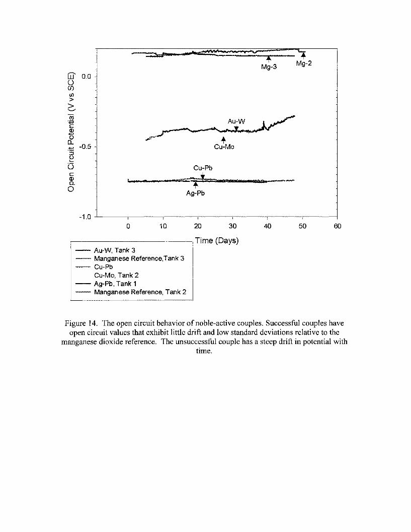
+Mg-3 Mg-2
,,--....0.0 -W
0if)(/)
>>'-"'"
ro+=icQ)
+-'0 "..., ;-0...
.;-
:t= -0.5 - Cu-Mo::s()L-
G Cu-Pbc :; ~*.;Q)
I lsi. • jJi r :Clitc..0
Ag-Pb
-1.0 -4----------,,.------..,..------.-------,-------,-------,-------1
o 10 20 30 40 50 60
-- Au-W, Tank 3--- Manganese Reference,Tank 3-....."., Cu-Pb
Cu-Mo, Tank 2- Ag-Pb, Tank 1-- Manganese Reference, Tank 2
Figure 14. The open circuit behavior of noble-active couples. Successful couples haveopen circuit values that exhibit little drift and low standard deviations relative to the
manganese dioxide reference. The unsuccessful couple has a steep drift in potential withtime.
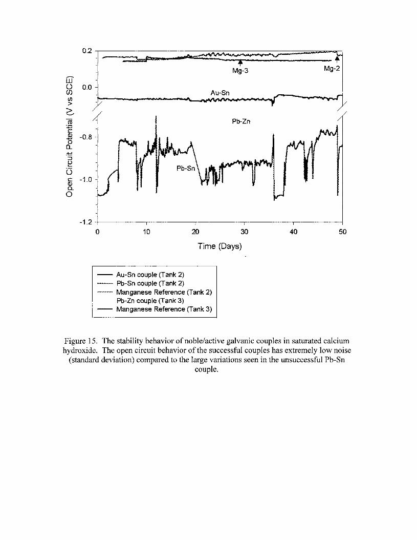
0.2
~
Mg-3 Mg-2,,--..W0 0.0(J) Au-Sn(/)
>>
~""---"
as Pb-Zn+:icQ) -0.8+-'0a..
:t:::!::J()L..
GcQ)c..0
5040302010
-1.2 -+-------r-------r-------r-------.--------I
o
Time (Days)
-- Au-Sn couple (Tank 2)-- Pb-Sn couple (Tank 2)~- Manganese Reference (Tank 2)
Pb-Zn couple (Tank 3)-- Manganese Reference (Tank 3)
Figure 15. The stability behavior of noble/active galvanic couples in saturated calciumhydroxide. The open circuit behavior of the successful couples has extremely low noise
(standard deviation) compared to the large variations seen in the unsuccessful Pb-Sncouple.

"'" _ _ .... \. _ ... _ ......... _ " _ ~ ..,. __ "'" '.. _ _- -I " ,. \. .......... .; '\ ... "" ... - "" .......... J' ~ .......... "" ". - - ... - ... - ....... - " ..... -
...-.. 0wU(J)
en>>'-'"
CO~
CQ.).......,0
a..:!:
:::::JUs....
GcQ)c..0
:•••:*'•••'••• " " ,,*"H~'..• • ~
; : ...............~ ,'... '
........ : .
:' -..- .I I....... :
'..--.. .... ".
-1 -+----------'T"--------,.---------,..----------r----------l
o 10 20 30 40 50
Time (Days)
...... Mo/Pb, Tank 2-- MolW, Tank 2- - - Manganese reference,Tank 2
Figure 16. The stability behavior of active-active galvanic couples in saturated calciumhydroxide shows that stable couples (Mo-W) have steady open circuit potentials like the
manganese dioxide reference electrode, but unstable electrodes (Mo-Pb) have largepotential shifts.

0.15 -,----------------------------------,
0.14 -
...-....W()en
0.13 -en>>""-""""ro
0.12 -:.t=ic:(1).....0a..
0.11 -
12108642o-2-4-6
0.10 -+-----r-,---r-'--.I-------rl-----r-,----r--I---.,.....-------r,------.-,-----l
-8
Current (uA)N N - - - - Anodic Polarization-- Cathodic Polarization
Figure 17. the micro-polarizability of true reference electrodes. The manganese dioxidereference electrode is shown.
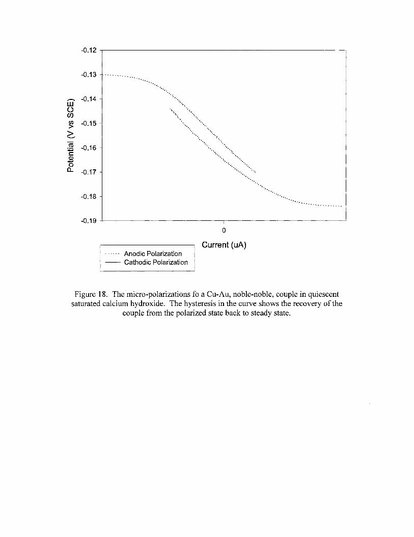
-0.12 .....------------------------------.,
-0.13
~ -0.14W()en~ -0.15
>...........co~ -0.16-cQ)
+-'oa.. -0.17-
-0.18 -
-0.19 --L.----------------r-I ----------------'
o
Current (uA)n n v v v» Anodic Polarization-- Cathodic Polarization
Figure 18. The micro-polarizations fo a eu-Au, noble-noble, couple in quiescentsaturated calcium hydroxide. The hysteresis in the curve shows the recovery of the
couple from the polarized state back to steady state.
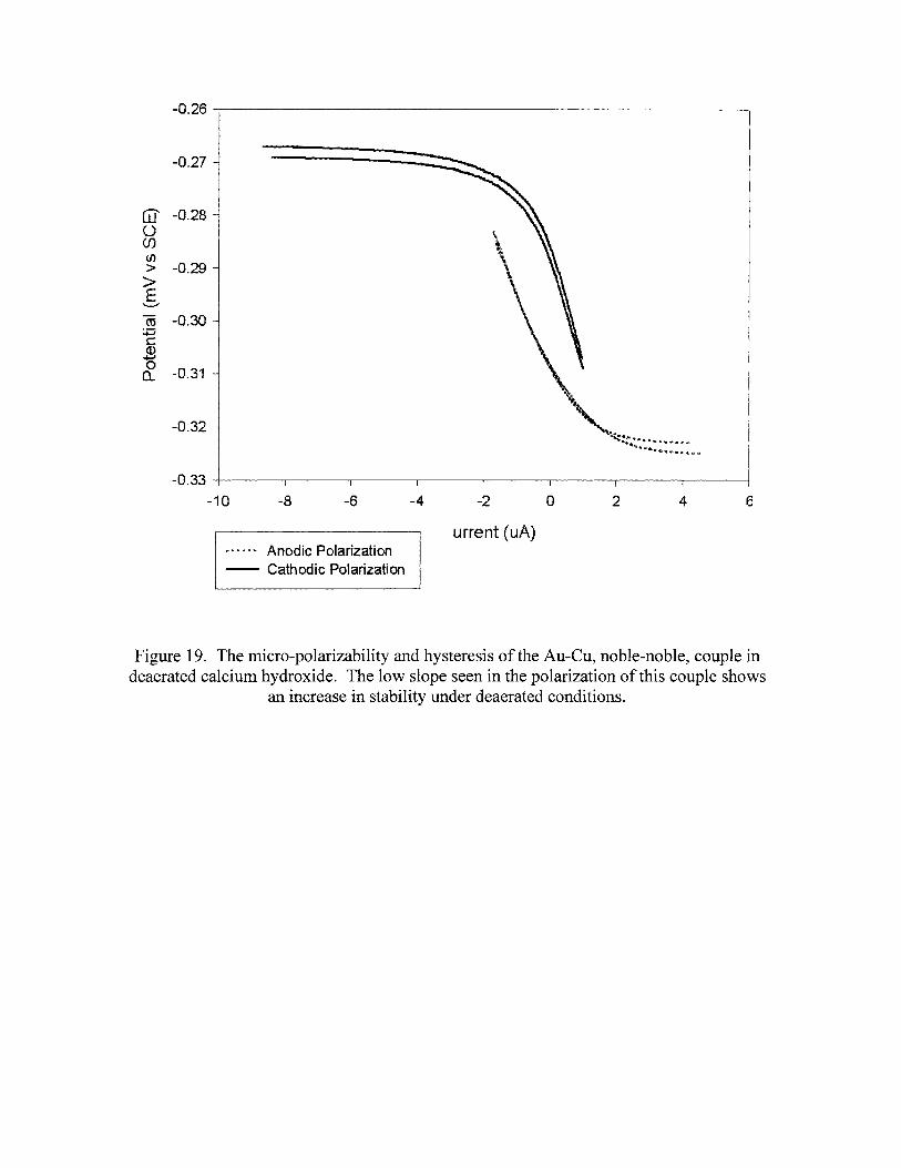
-0.26
-0.27
(i]' -0.280(J)(/)
> -0.29>E
.......",
ctS -0.30+:icCD+-'0
-0.31a..
-0.32
-0.33
-10 -8 -6
Anodic Polarization-- Cathodic Polarization
-4 -2
urrent (uA)
o 2 4 6
Figure 19. The micro-polarizability and hysteresis of the Au-eu, noble-noble, couple indeaerated calcium hydroxide. The low slope seen in the polarization of this couple shows
an increase in stability under deaerated conditions.

-0.744
-0.746
-0.748,...........Wl)
-0.750enen>> -0.752..........
co~c: -0.754Q)
+oJ
aa..
-0.756
-0.758
2015105o
Current (uA)
-5-10-15
-0.760 -+----~--~----.-------.-----~-----.------.-----1
-20
~ x ~ ~ u u Anodic Polarization-- Cathodic Polarization
Figure 20. The micro-polarizability of the Ag-Pb, noble-active couple in quiescentsaturated calcium hydroxide. The anode control of this couple provides high stability and
low polarizability.
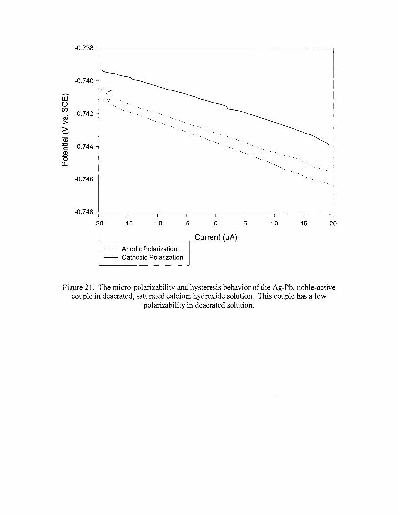
-0.738 -,-----------------------------.,
-0.740
;r....-..W ' ~J0C/)
-0.742en>>"'-"
co~ -0.744cQ).......0a..
-0.746'-' ..
2015105o
Current (uA)
-5-10-15
-0.748 ""'-1-----r---~--~---~--_...__--_____,;___--___,....__--__,
-20
N N N A A - Anodic Polarization-- Cathodic Polarization
Figure 21. The micro-polarizability and hysteresis behavior of the Ag-Pb, noble-activecouple in deaerated, saturated calcium hydroxide solution. This couple has a low
polarizability in deaerated solution.

-0.02
-0.03
-0.04...-....W0 -0.05(f)(/)
>> -0.06.............
ro+:ic
-0.07(I)......,0a..
-0.08
-0.09
-0.10
-0.3 -0.2 -0.1 0.0 0.1
Current (uA)
,. ...... -« Anodic Polarization-- Cathodic Polarization
0.2 0.3 0.4
Figure 22. The micro-polarizability and hysteresis behavior of the Au-Sn, noble-passivecouple in quiescent saturated calcium hydroxide. This couple exhibits limited hysteresis,
returning to steady state readily.
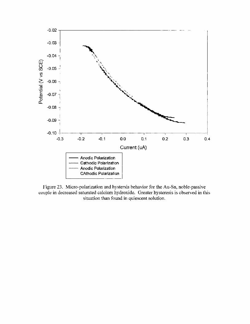
-0.02
-0.03
-0.04.............W0
-0.05(J)(/)
>> -0.06""-"
ro+:ic
-0.07CD+"0a..
-0.08
-0.09
-0.10
-0.3 -0.2 -0.1 0.0 0.1 0.2 0.3 0.4
-- Anodic Polarization-- Cathodic Polarization-- Anodic Polarization
CAthodic Polarization
Current (uA)
Figure 23. Micro-polarization and hystersis behavior for the Au-Sn, noble-passivecouple in decreased saturated calcium hydroxide. Greater hysteresis is observed in this
situation than found in quiescent solution.
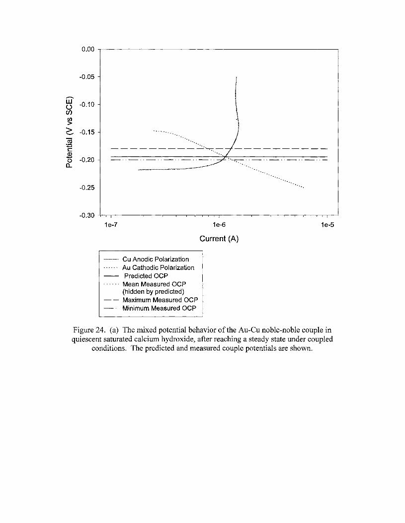
0.00 --r--------------------------~
-0.05
.............W -0.10()enen>> -0.15............
ro+:ic:Q).......
-0.200a..
-0.25 ...
1e-7
---------- Cu Anodic PolarizationA ~ ~ ~ ~ y Au Cathodic Polarization-- Predicted OCP. . . . .. Mean Measured OCP
(hidden by predicted)- - Maximum Measured OCP
Minimum Measured OCP
1e-6
Current (A)
1e-5
Figure 24. (a) The mixed potential behavior of the Au-eu noble-noble couple inquiescent saturated calcium hydroxide, after reaching a steady state under coupled
conditions. The predicted and measured couple potentials are shown.
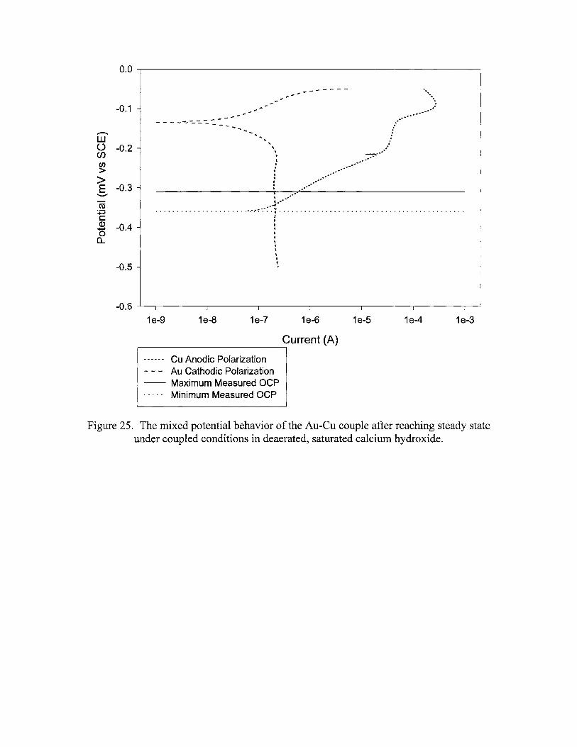
0.0 ..-------------------------------,
, ...... .. . . . . . . . . . . . . . . . . . . . . ':' ..-~.:~.~ .
I)
•t)
•,.~
l\."
-0.1
...-...W() -0.2enen>>E -0.3
..........
co+:iCQ) -0.4.....0a..
-0.5
-------..,.- - - -~-:... -"- ........
-. , ...,,•...f
t
:,..)I
..... .",.,.~----............/.....
--:-..-. .
..................
-0.6 ....1..-----.-----..,.----------r-------.-----..,.----------r-------.---.J
1e-9 1e-8 1e-7 1e-6 1e-5 1e-4 1e-3
Current (A),....-----------------,
...... Cu Anodic Polarization- - - Au Cathodic Polarization-- Maximum Measured OCP. . . .. Minimum Measured OCP
Figure 25. The mixed potential behavior of the Au-eu couple after reaching steady stateunder coupled conditions in deaerated, saturated calcium hydroxide.
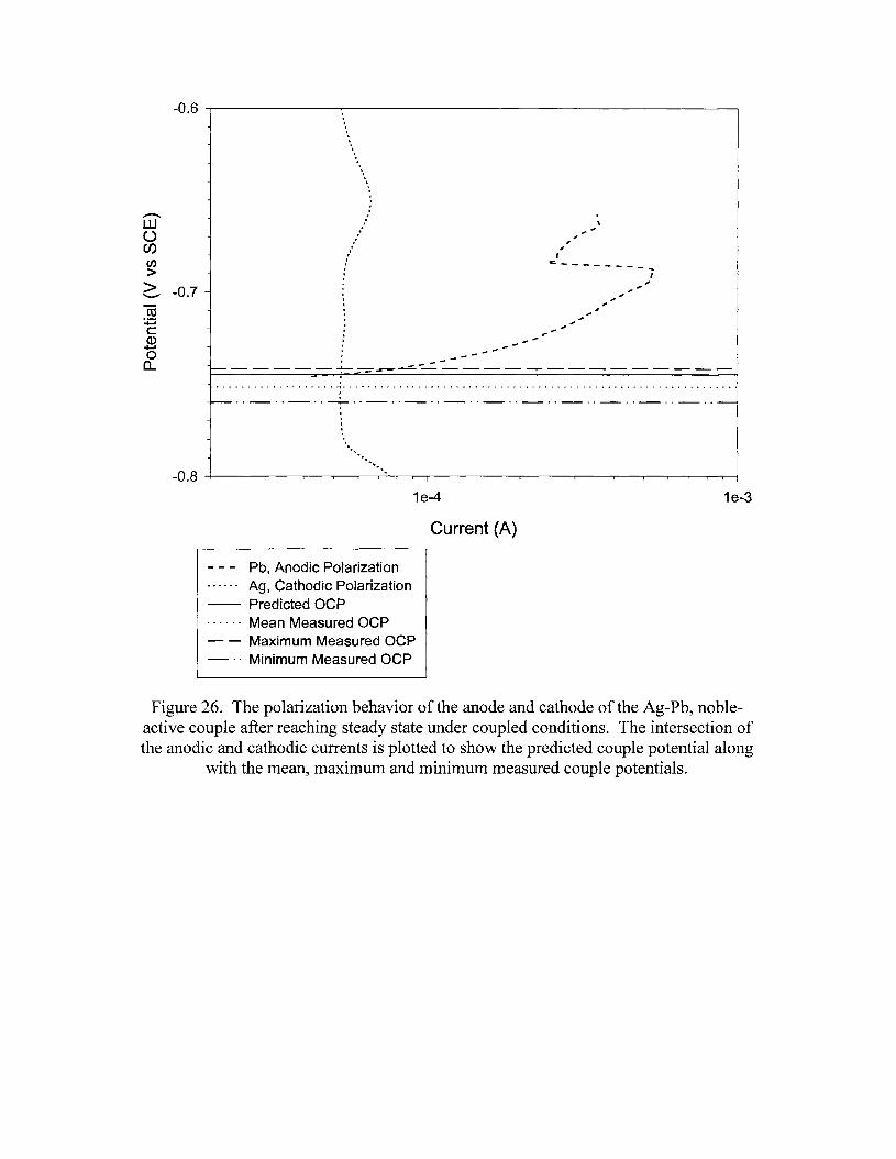
-0.6 ~--------.--------------------------.
-----------~~~~~~-------------
...-....w()en~2::, -0.7-co
:+:ic:Q)......oa..
\.".,,,,c _
I,.
_ .. _ .. - .. -.- .. - .. _ .. _ .. _ .. _ .. _ .. _ .. _ .. - .. -
..........-0.8 -t-----r----,----,.--r-.......--"'"-,--....----r,------,.----r------,--.,....---,.-r----l.-----r---i
1e-4
Current (A)
- - - Pb, Anodic Polarization~ ~ ~ ~ -- Ag, Cathodic Polarization-- Predicted OCP. . . . .. Mean Measured OCP- - Maximum Measured OCP- .. Minimum Measured OCP
1e-3
Figure 26. The polarization behavior of the anode and cathode of the Ag-Pb, nobleactive couple after reaching steady state under coupled conditions. The intersection ofthe anodic and cathodic currents is plotted to show the predicted couple potential along
with the mean, maximum and minimum measured couple potentials.
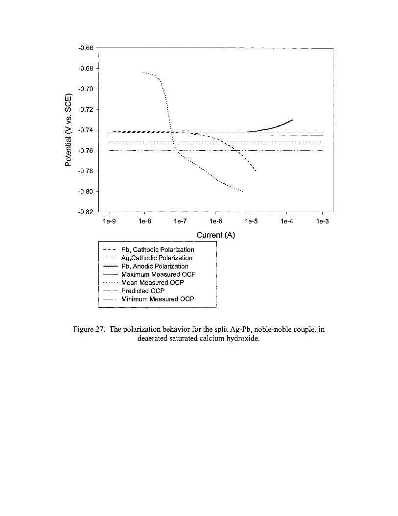
-0.66
-0.68
-0.70...-....W()en -0.72en>> -0.74"-'
ro~c:: -0.76Q)+-'0a..
-0.78
......... ""'..,
-----~~~~~~---~---: ""'- ...••••••••••••••••••••••• 1••••••••••••••••• "- •••••••••••••••••••••••••••••••••••. ", ....
\ ...._ .. _ .. _ .. _ ..,_ .. _ .. _ .. -----..- .. _ .. _ .. _ .. _ .. -.." "
~... ,.... "
"""
-0.80
-0 .82 -L----r------r--------r--------r-----~--____,---__r_-----I
1e-9 1e-8 1e-7 1e-6
Current (A)
1e-5 1e-4 1e-3
Pb, Cathodic PolarizationAg,Cathodic Polarization
-- Pb, Anodic Polarization-- Maximum Measured OCP...... Mean Measured OCP- - Predicted OCP_. Minimum Measured OCP
Figure 27. The polarization behavior for the split Ag-Pb, noble-noble couple, indeaerated saturated calcium hydroxide.
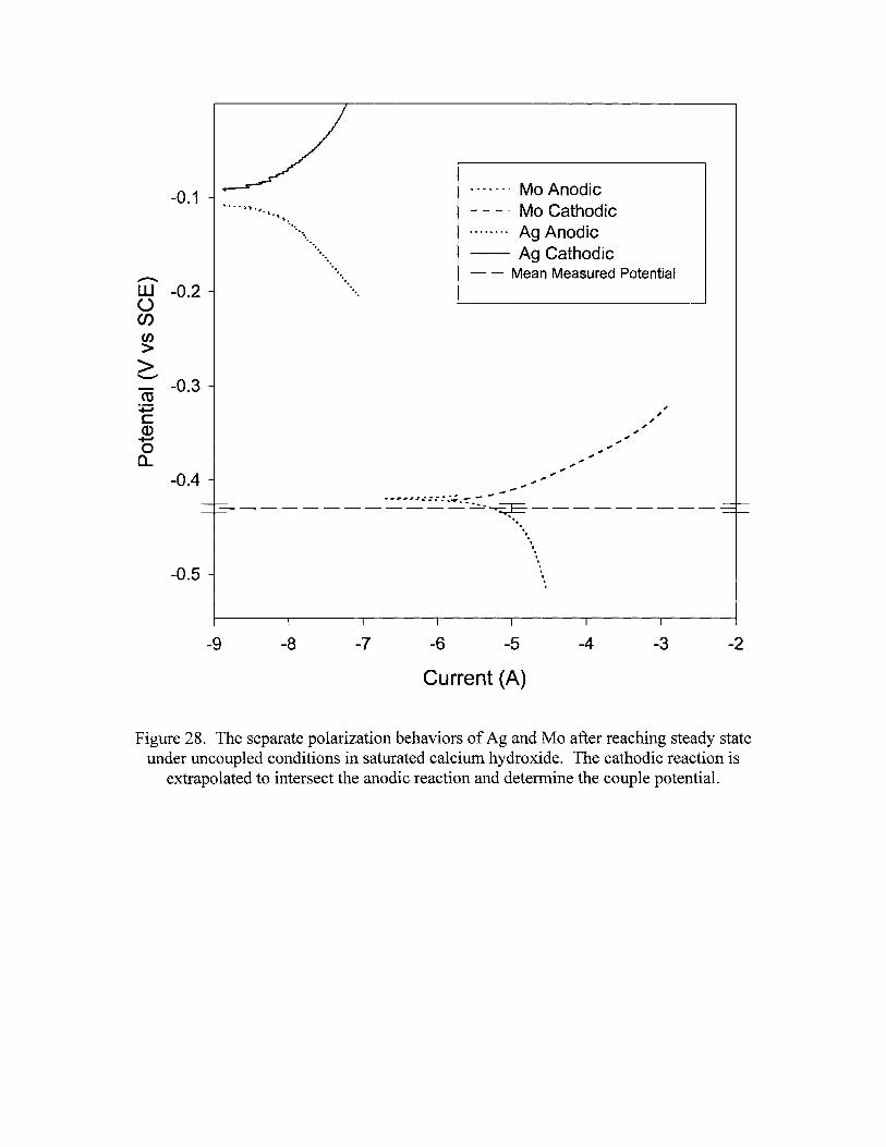
-0.1
~
W -0.2Uenen>>'-"'"
-0.3co+:iC(1)
+-Ioa..
.... ~, ". I."\. .
......................•......
*M*M __ • Mo Anodic- - _. Mo Cathodic. Ag Anodic-- Ag Cathodic- - Mean Measured Potential
-0.4
-0.5
________=~~~-~.7_~~ _.........
......,...
-9 -8 -7 -6 -5 -4 -3 -2
Current (A)
Figure 28. The separate polarization behaviors of Ag and Mo after reaching steady stateunder uncoupled conditions in saturated calcium hydroxide. The cathodic reaction is
extrapolated to intersect the anodic reaction and determine the couple potential.
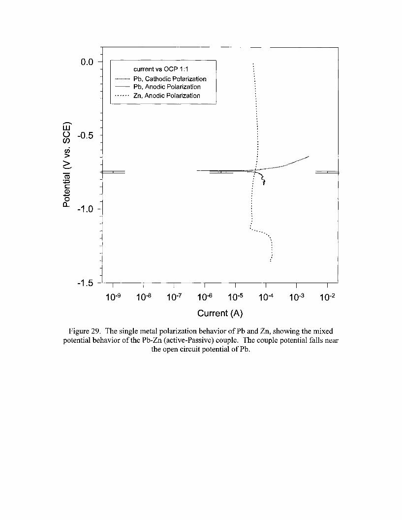
0.0 --
-current vs OCP 1:1
.............. Pb, Cathodic Polarization-- Pb, Anodic PolarizationN N. N ¥ ¥ Zn, Anodic Polarization
-
I
10-2
I
10-3
I
10-4
......
......................
··:..K····················
I
10-5
Current (A)
....--..w() -0.5 -enen> ->'-""ctS
.., .
~-
c -Q)~
0 -0...-1.0
-
-
-
-
-
-1.5 I I I I
10-9 10-8 10-7 10-6
Figure 29. The single metal polarization behavior of Pb and Zn, showing the mixedpotential behavior of the Pb-Zn (active-Passive) couple. The couple potential falls near
the open circuit potential of Pb.
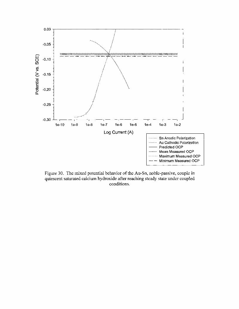
0.00 ~------------.......--------------------,
-0.05
............................. :~ : .
wo -0.10enen>~ -0.15
co+:ic:Q)
15 -0.20a..
-0.25.~.
..............::-0.30 ....L...-.-,......---~----,,....--.---r----..-----,......---~------,r---~~
1e-10 1e-9 1e-8 1e-7 1e-6 1e-5 1e-4 1e-3 1e-2
Log Current (A)........ Sn Anodic Polarization------ Au Cathodic Polarization-- Predicted OCP---------- Mean Measured OCP...... Maximum Measured OCP- - Minimum Measured OCP
Figure 30. The mixed potential behavior of the Au-Sn, noble-passive, couple inquiescent saturated calcium hydroxide after reaching steady state under coupled
conditions.
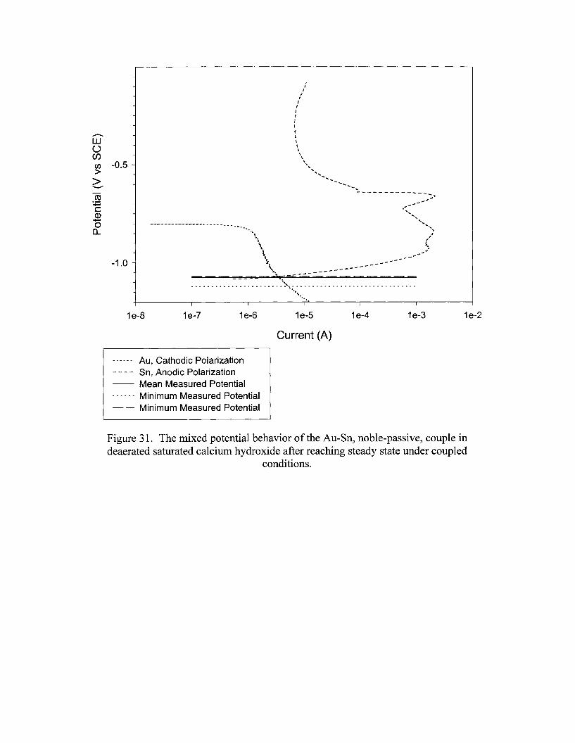
......'"'-~\
\,~
\.. -----___=;;=; 4.,.c....- - - -
/I
It
III(
II,t\\\\\~
""-,
' .... ............. ~--..... ..... "';..
-----------"'-.~""
\,........................ ": ...~..
'-.
..-....w()Cf)
en -0.5>>'-'"
as~cQ).....,00..
-1.0
1e-B 1e-7 1e-6 1e-5 1e-4 1e-3 1e-2
Current (A)
...... Au, Cathodic Polarization- - - - Sn, Anodic Polarization-- Mean Measured Potential...... Minimum Measured Potential- - Minimum Measured Potential
Figure 31. The mixed potential behavior of the Au-Sn, noble-passive, couple indeaerated saturated calcium hydroxide after reaching steady state under coupled
conditions.
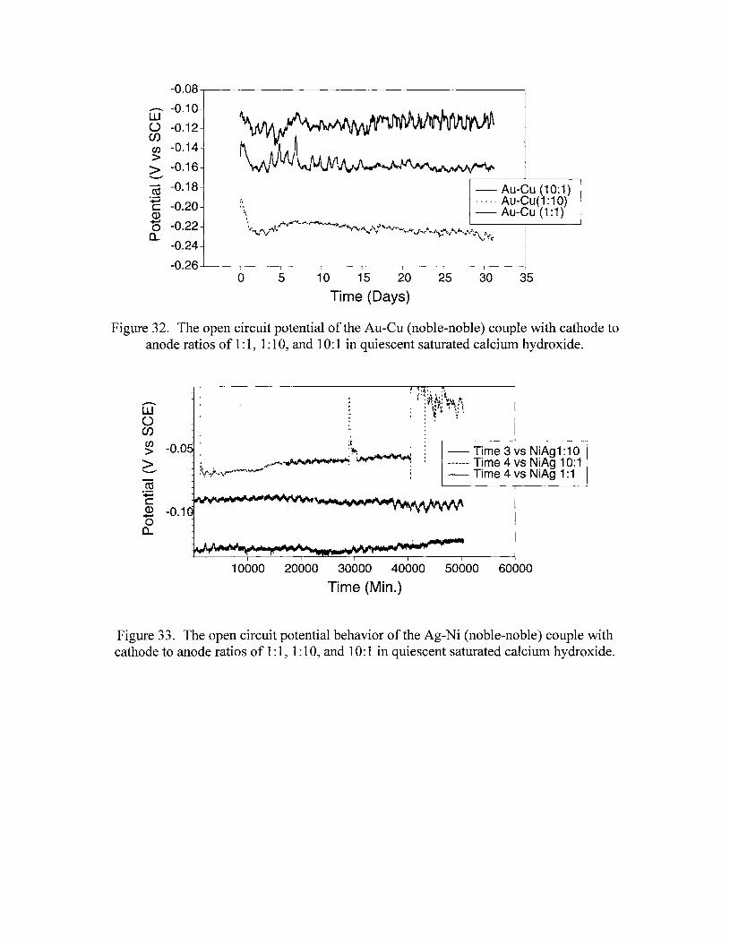
- Au-Cu (10:1)----- Au-Cu(1:10)- Au-Cu (1:1)
'I
'\" 1."r..y""",..- .....~...,.......... - .,', .....~.#-""\/\,/"'i'" ~'o'''\', .. -...H-,l.....It...~...:.*\/,,~rJf....;'\__.., 'op
,.":1(
-0.08-.---------------------------.
~ -0.10UJ() -0.12enen -0.14>> -0.16
'-""
ctS -0.18~c: -0.20Q)
"0 -0.22a..
-0.24
-0.26....1...------r-------r--------.----r----,.---------.----,------lo 5 10 15 20
Time (Days)25 30 35
Figure 32. The open circuit potential of the Au-eu (noble-noble) couple with cathode toanode ratios of 1: 1, 1: 10, and 10: 1 in quiescent saturated calcium hydroxide.
~
W()en~ -0.0>'-""ctS~c:~ -0.1oa..
·Ii', "• /01;'. I If., :~~'t t.'\!~.• \: .. I,' t: : t· ~'
- Time 3 vs NiAg1:1 0------ Time 4 vs NiAg 10: 1- Time 4 vs NiAg 1:1
10000 20000 30000 40000 50000 60000
Time (Min.)
Figure 33. The open circuit potential behavior of the Ag-Ni (noble-noble) couple withcathode to anode ratios of 1:1, 1: 10, and 10:1 in quiescent saturated calcium hydroxide.

-0.20 -- Ag-Mo (1:10)-- Ag-Mo (10:1)"~9«"" Ag-Mo(1:1)
-0.25
.............W0 -0.30(J)(/)
>> -0.35"----'
ro+:icQ) -0.40+-'0
0..
-0.45
-0.50
o 5 10 15
Time (Days)
20 25 30 35
Figure 34. The effect of varying cathode to anode area ratios (1: 1, 1: 10, and 10: 1) on theopen circuit behavior of the Ag-Mo (noble-active) couple in quiescent saturated calcium
hydroxide.
r~~~~
-- Cu-Mo(1:10)_ Cu-Mo (10:1)
I .. Cu-Mo (1 :1)
-0.15
-0.20
W' -0.250(J)(/)
-0.30>>"----'ro -0.35
'+:icQ)
+-' -0.4000..
-0.45
-0.50o 5 10 15 20 25 30 35
Time (Days)
Figure 35. the effect of varying cathode to anode area ratios (1: 1, 1: 10, and 10: 1) on theopen circuit behavior of the Cu-Mo (noble-active) couple in quiescent saturated calcium
hydroxide.
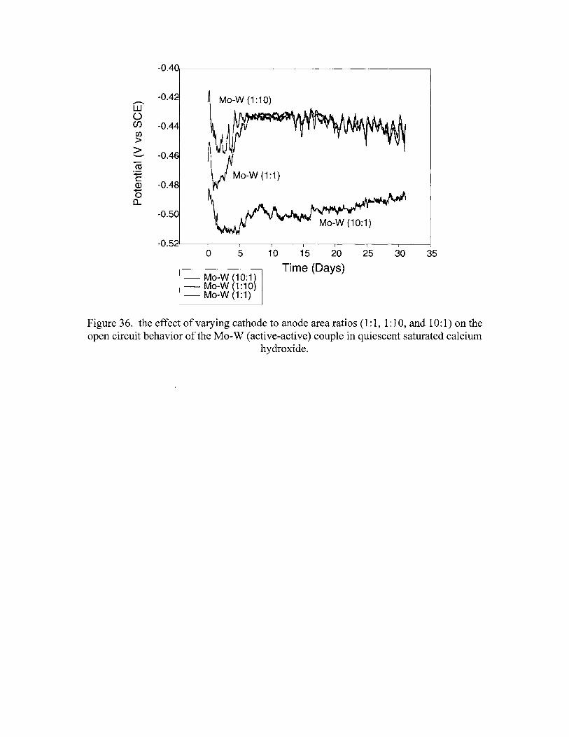
-0.4
-0.4..--....W(.)Cf) -0.4en>> -0.4""'-'"
CO-.;::;c
-0.4Q)......,0a..
-0.5
-0.5o 5
- Mo-W i10:1)- Mo-W 1:10)- Mo-W 1:1)
10 15 20
Time (Days)25 30 35
Figure 36. the effect of varying cathode to anode area ratios (1:1,1:10, and 10:1) on theopen circuit behavior of the Mo-W (active-active) couple in quiescent saturated calcium
hydroxide.
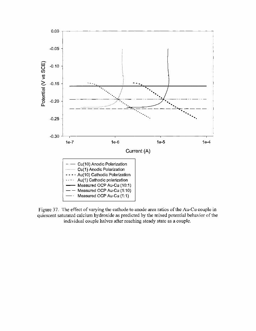
0.00 --r--------------------------------.
-0.05 -
............
~ -0.10enen>~ -0.15-ro+:icQ)
15 -0.20a..
-0.25 -
-.-.
-0.30 -'---.-----1--------r-1--------r---1---------T'"1---J
1e-7 1e-6
Current (A)
1e-5 1e-4
-- Cu(1 0) Anodic Polarization........ Cu(1) Anodic Polarization- - - · Au(10) Cathodic Polarization'" '" '" * Au(1) Cathodic polarization-- Measured OCP Au-Cu (10:1)- - Measured OCP Au-Cu (1 :10)_. Measured OCP Au-Cu (1:1)
Figure 37. The effect of varying the cathode to anode area ratios of the Au-eu couple inquiescent saturated calcium hydroxide as predicted by the mixed potential behavior of the
individual couple halves after reaching steady state as a couple.

0.0
......-...N
0C~en>> -0.1E"'-"
co+:iCQ.)
'+oJ
0a..
-0.2
I,• ~ ... :~.~ ,~ I "I: I • i" . •1 '." '~l H ~,Il' ,~ ,1:.\ '\ -. ~l ", i I : I :: ~: ., , :";:\ "::;::S.If: 'rI~..~,.~.11:~.+$...••.1.+..11,;1.·.::M__~ .rl ~~I .._ _ .~1~ ',,,iii ,." ~. Kt " :. ~ ,"'i" ,,'1: ~"\''f~, "tI. • ", ": I ." '! ,~I , ,I", ~ ~ ) ,'n ~, \, :r I ",~" ",' ': • I, 'I:" I 1, ! ~ •
. . .. . . Manganese Dioxide Reference 1
-- Manganese Dioxide Reference 2
-- Ag/AgCI Reference
o 168 336 504 672 840 1008 1176 1344 1512
Time (Hours)
Figure 38. The reference potentials for the manganese dioxide and silver chloridecommercial electrodes in concrete over 2000 hours. The stability of the Ag/Agelelectrode is plotted as determined against both manganese electrodes. All three
electrodes show similar, stable behavior. The standard deviations of these electrodes arecaused by noise and drift.
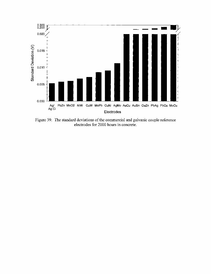
0.300)/0.200
0.020
>''-""c 0.015o
+:;co.S;(J.)
oE 0.010co
"'0Ccoen
0.005
0.000
----II}
Electrodes
Agl PbZn Mn02 NiW CuW MoPb CuNi AgMo AuCu AuSn CuZn PbAg PbCu MoCuAgCI
Figure 39. The standard deviations of the commercial and galvanic couple referenceelectrodes for 2000 hours in concrete.
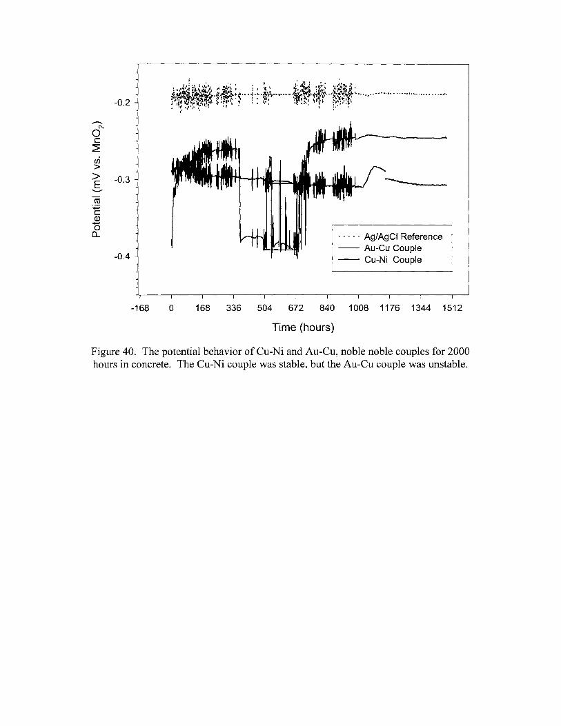
- - - - - Ag/AgCI Reference-- Au-Cu Couple-- Cu-Ni Couple
-0.2
..--...C'\l
0C~
en>> -0.3E"-"
rn+:icQ)~
0a..
-0.4
-168 o 168 336 504 672 840 1008 1176 1344 1512
Time (hours)
Figure 40. The potential behavior of Cu-Ni and Au-Cu, noble noble couples for 2000hours in concrete. The Cu-Ni couple was stable, but the Au-Cu couple was unstable.
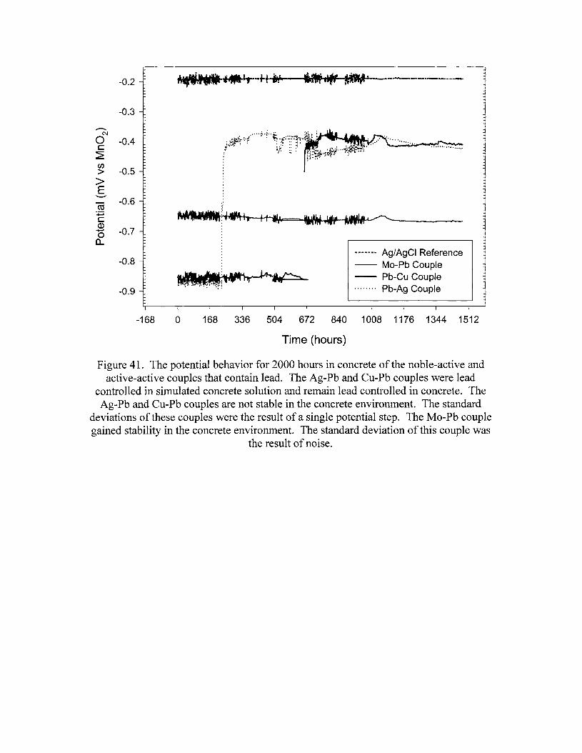
...'fr .'-------..-----------0.2
-0.3
....-...N
0 -0.4c~en
-0.5>>E
'--""-0.6co
:;::;c(1)
-0.7+-'0
a..
-0.8
-0.9
_W'" ~.... .. ~: .~:. ~
------- Ag/AgCI Reference-- Mo-Pb Couple-- Pb-Cu Couple. Pb-Ag Couple
-168 o 168 336 504 672 840 1008 1176 1344 1512
Time (hours)
Figure 41. The potential behavior for 2000 hours in concrete of the noble-active andactive-active couples that contain lead. The Ag-Pb and Cu-Pb couples were lead
controlled in simulated concrete solution and remain lead controlled in concrete. TheAg-Pb and Cu-Pb couples are not stable in the concrete environment. The standard
deviations of these couples were the result of a single potential step. The Mo-Pb couplegained stability in the concrete environment. The standard deviation of this couple was
the result of noise.
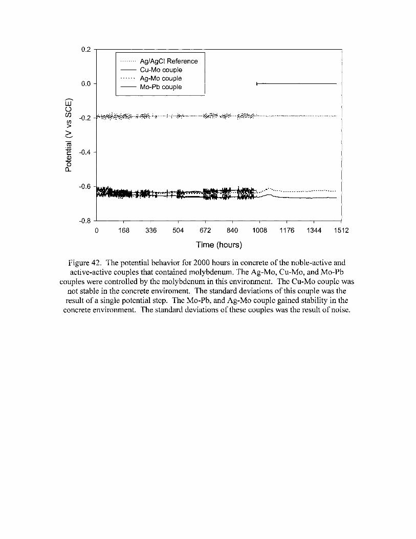
0.2 .....-------------------------------,
0.0
........ Ag/AgCI Reference-- Cu-Mo couple------ Ag-Mo couple-- Mo-Pb couple
...........W()(J) -0.2 .' ~~~~i:~¥~'*~··~~·~~~;.·1:····-~·~··~'- ..··- · !!*;~~:~·~~t·~···f':~"'..~!>;1+·~··············· .. ······ ..········· .. ······ .en>>--..,...co~ -0.4(I).....,oa..
-0.6.. _ •••• a •••••••••••
-0.8 -+-----.-------r--------r-------r-----r-----.--~--__,--____T
o 168 336 504 672 840 1008 1176 1344 1512
Time (hours)
Figure 42. The potential behavior for 2000 hours in concrete of the noble-active andactive-active couples that contained molybdenum. The Ag-Mo, Cu-Mo, and Mo-Pb
couples were controlled by the molybdenum in this environment. The Cu-Mo couple wasnot stable in the concrete enviroment. The standard deviations of this couple was theresult of a single potential step. The Mo-Pb, and Ag-Mo couple gained stability in the
concrete environment. The standard deviations of these couples was the result of noise.

,',. '" •. _,I, I III.'~"· ~.I., ".\/J.t!t·'.i ~~~··j~"i~.~""" It' ~•••••t .....~__--""""\vJ~1 ••...,6 ~ :r;I~jj" •••••••••- •••••••••••••••••••••••••••••••••H'~'"'f{~"'~~ -,~~ I,; t,-:n'-" ~~ ..• \,,"i' ~~,)"';
-0.1
-0.2
-0.3.....-...wUen -0.4en>> -0.5'-"'"
CO:;:::;c -0.6Q).......0a..
-0.7
-0.8
-0.90 168 336 504 672 840
...... Ag/AgCI reference-- Ni-W couple-- Cu-W couple
1008 1176 1344 1512
Time (hours)
Figure 43. The potential behavior for 2000 hours in concrete of the noble-active couplesthat contained tungsten. The Ni-Wand Cu-W couples both exhibit stable potentials in
concrete. Their standard deviations occur as noise.
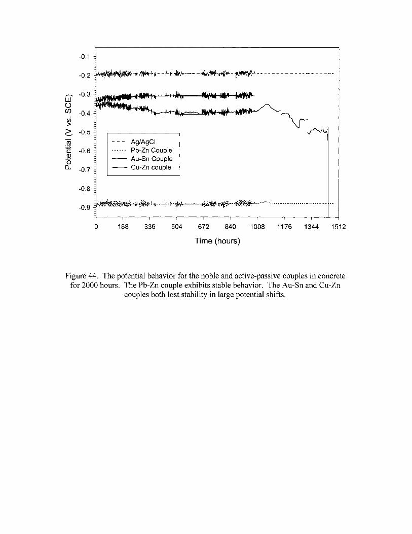
-0.1
-0.2
,........ -0.3w0en -0.4(J)
>> -0.5'-""
ro~
-0.6c:Q).....,0a.. -0.7
-0.8
-0.9
- - - Ag/AgCI-.. -.- Pb-Zn Couple-- Au-Sn Couple-- Cu-Zn couple
'~'~""P ',1 ~,.,. ..~'~ .'", ,.,="~••,I,, ••••~ ~~'-'..-.JrL.J;./. .. +_ •• _"'_ ~- -+:> ~~if. I .lJI:.\i\\ ~.. .. - - _ - ••••• _.... .-,... ...~,~m~p-. 0' .. • '" I ,r"'lII'" 'ill ...~,. I(V:~" I
o 168 336 504 672 840 1008 1176 1344 1512
Time (hours)
Figure 44. The potential behavior for the noble and active-passive couples in concretefor 2000 hours. The Pb-Zn couple exhibits stable behavior. The Au-Sn and Cu-Zn
couples both lost stability in large potential shifts.
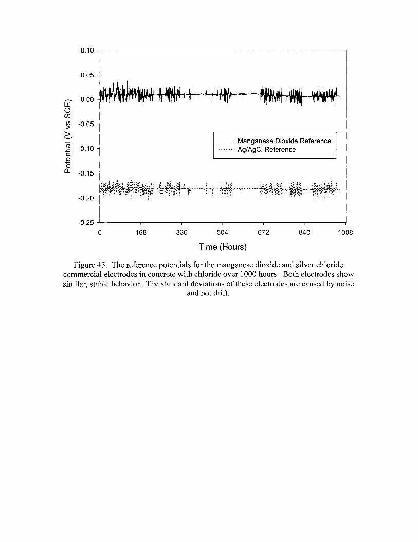
0.10
0.05
....--.. 0.00W()(J)
en -0.05>>"'-'"co -0.10~cQ)
+-'0(L -0.15
-0.20
-- Manganese Dioxide Reference•• N N A ~ Ag/AgCI Reference
-0.25 -+-----,...----------,-----,---------r------,------,.J
o 168 336 504
Time (Hours)
672 840 1008
Figure 45. The reference potentials for the manganese dioxide and silver chloridecommercial electrodes in concrete with chloride over 1000 hours. Both electrodes showsimilar, stable behavior. The standard deviations of these electrodes are caused by noise
and not drift.
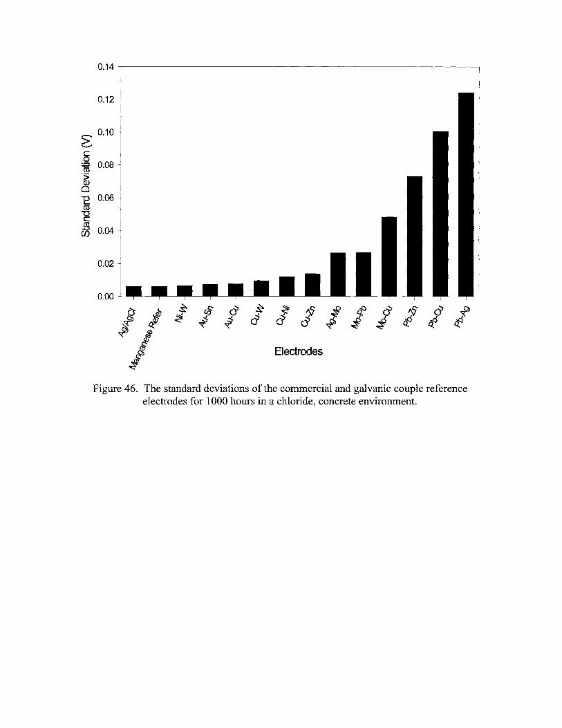
0.14 ~---------------------------------..
0.12
~ 0.10
co~ 0.08.~
o~ 0.06co-ccm0.04
0.02
0.00
g ~S t5 a s ~ '9 ~ if a f a ~
~ ~ .::S .::S a a a fJ ~ ~ tf tf~ IJ? ~ ~q:
~ ~~~ Electrodes
.!Figure 46. The standard deviations of the commercial and galvanic couple reference
electrodes for 1000 hours in a chloride, concrete environment.
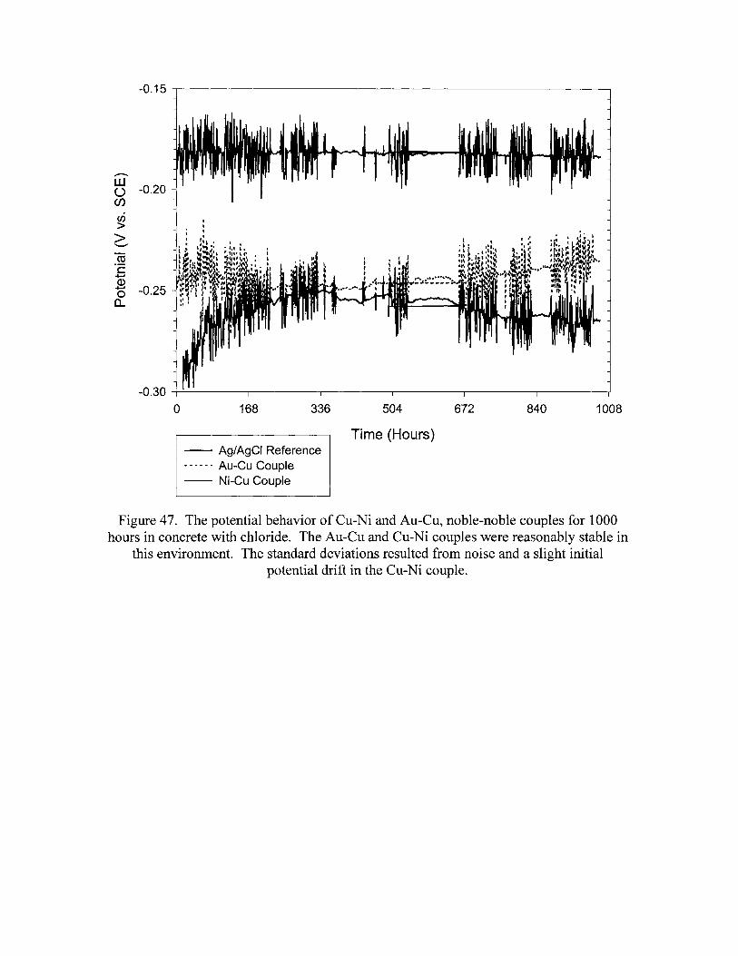
-0.15 -,----------------------------,
.............W
-0.200C/)
en>>"'-"".~c~
Q)~ -0.250a..
-0.30 --T--L-----,-------,-----~---r__--_r___--__r
-- Ag/AgCI Reference-- - - _. Au-Cu Couple-- Ni-Cu Couple
o 168 336 504
Time (Hours)
672 840 1008
Figure 47. The potential behavior ofCu-Ni and Au-Cu, noble-noble couples for 1000hours in concrete with chloride. The Au-Cu and Cu-Ni couples were reasonably stable in
this environment. The standard deviations resulted from noise and a slight initialpotential drift in the Cu-Ni couple.
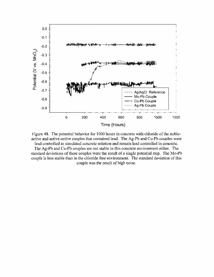
0.0
-0.1
-0.2~
N
0 -0.3c~
CJ) -0.4>>'-"" -0.5co
:.;:::;c -0.6Q)......,0a.. -0.7
-0.8
-0.9
---- Ag/AgCI Reference-- Mo-Pb Couple-- Cu-Pb Couple
Ag-Pb Couple
o 200 400 600 800 1000 1200
Time (Hours)
Figure 48. The potential behavior for 1000 hours in concrete with chloride of the nobleactive and active-active couples that contained lead. The Ag-Pb and Cu-Pb couples were
lead controlled in simulated concrete solution and remain lead controlled in concrete.The Ag-Pb and Cu-Pb couples are not stable in this concrete environment either. The
standard deviations of these couples were the result of a single potential step. The Mo-Pbcouple is less stable than in the chloride free environment. The standard deviation of this
couple was the result of high noise.
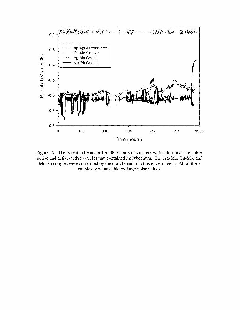
-0.6
-0.2
-0.3~
W()
en -0.4en>>'-"'"ro -0.5~cQ)~
oa..
-0.7
. .. .... Ag/AgCI Reference-- Cu-Mo Couple- .. _. Ag-Mo Couple-- Mo-Pb Couple
-0.8 -+------r---------r--------r-----.,..-----~----~
o 168 336 504
Time (hours)
672 840 1008
Figure 49. The potential behavior for 1000 hours in concrete with chloride of the nobleactive and active-active couples that contained molybdenum. The Ag-Mo, Cu-Mo, andMo-Pb couples were controlled by the molybdenum in this environment. All of these
couples were unstable by large noise values.
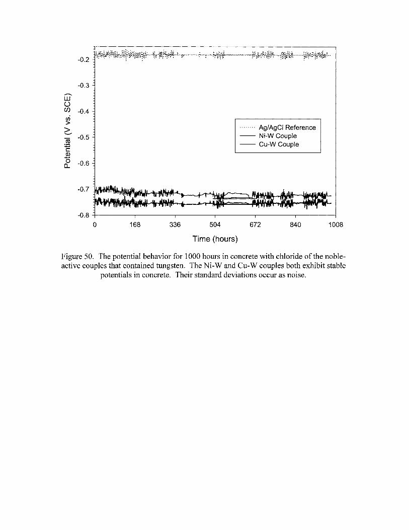
-0.2
-0.3.............w()
en -0.4(/)
>>"-'"CO -0.5
+:icQ)
+-I
&. -0.6
........ Ag/AgCI Reference-- Ni-W Couple-- Cu-W Couple
-0.8 -+---------r-------...-------r--------,.----.--------;
o 168 336 504
Time (hours)
672 840 1008
Figure 50. The potential behavior for 1000 hours in concrete with chloride of the nobleactive couples that contained tungsten. The Ni-Wand Cu-W couples both exhibit stable
potentials in concrete. Their standard deviations occur as noise.
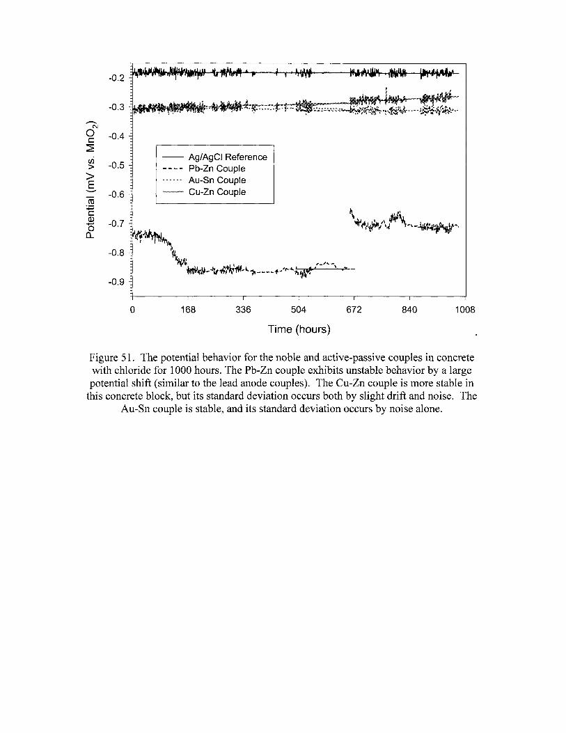
-0.2
-0.3..-...
C\J
0 -0.4c~
en -0.5>>E
'-"" -0.6co
:;:;cQ)
-0.7.......0(L
-0.8
-0.9
-- Ag/AgCI Reference- - - - Pb-Zn Couple------ Au-Sn Couple"'-- Cu-Zn Couple
o 168 336 504
Time (hours)
672 840 1008
Figure 51. The potential behavior for the noble and active-passive couples in concretewith chloride for 1000 hours. The Pb-Zn couple exhibits unstable behavior by a largepotential shift (similar to the lead anode couples). The Cu-Zn couple is more stable in
this concrete block, but its standard deviation occurs both by slight drift and noise. TheAu-Sn couple is stable, and its standard deviation occurs by noise alone.

TABLES


Table 1. Galvanic couple electrode test set.
Testing Testing TestingCouple Tank Continued Couple Tank tontinued Couple Tank Continued
? ? ?Ag-Pb 1 y Au-Sn 2 y Cu-Pb 3 yPt-Cu 1 Cu-Mo 2 y Ni-Pb 3Au-Cu 1 y Ni-W 2 y Pb-Zn 3 yAu-Ag 1 Mo-Sn 2 W-Pb 3Ag-Ni 1 Mo-W 2 Mo-Zn 3Pt-Au 1 Ni-Mo 2 Ni-Zn 3Zn-Sn 1 Ag-Mo 2 y Au-Zn 3Cu-Ni 1 y Cu-Sn 2 Au-Zn 3
(foil)Ag-Cu 1 W-Sn 2 Au-W 3Pt-W 1 Ag-Sn 2 Ni-Sn 3
Cu-Zn 1 y Ag-W 2 Ag-Zn 3W-Zn 1 Cu-W 2 y Au-Ni 3Cu-AI 1 Mo-Pb 2 y Cu-Ni 3AI-Zn 1 Pb-Sn 2 Au-W 2
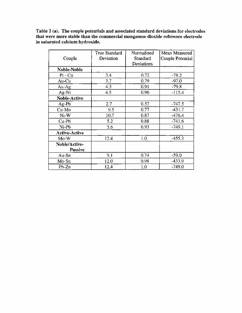
Table 2 (a). The couple potentials and associated standard deviations for electrodesthat were more stable than the commercial manganese dioxide reference electrodein saturated calcium hydroxide.
True Standard Normalized Mean MeasuredCouple Deviation Standard Couple Potential
DeviationsNoble-NoblePt - Cu 3.4 0.72 -78.2
Au-Cu 3.7 0.79 -97.0Au-Ag 4.3 0.91 -79.8Ag-Ni 4.5 0.96 -115.4
Noble-ActiveAg-Pb 2.7 0.57 -747.5
Cu-Mo 9.5 0.77 -431.7Ni-W 10.7 0.87 -476.4
Cu-Pb 5.2 0.88 -741.6Ni-Pb 5.6 0.93 -749.1
Active-ActiveMo-W 12.4 1.0 -455.3
Noble!Active-Passive
Au-Sn 9.1 0.74 -59.0Mo-Sn 12.0 0.98 -433.9Pb-Zn 12.4 1.0 -749.0
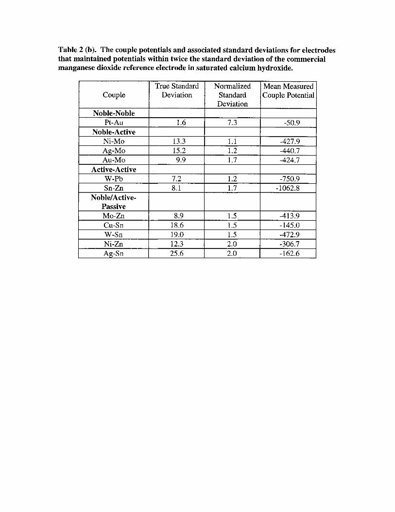
Table 2 (b). The couple potentials and associated standard deviations for electrodesthat maintained potentials within twice the standard deviation of the commercialmanganese dioxide reference electrode in saturated calcium hydroxide.
True Standard Normalized Mean MeasuredCouple Deviation Standard Couple Potential
DeviationNoble-Noble
Pt-Au 1.6 7.3 -50.9Noble-Active
Ni-Mo 13.3 1.1 -427.9Ag-Mo 15.2 1.2 -440.7Au-Mo 9.9 1.7 -424.7
Active-ActiveW-Pb 7.2 1.2 -750.9Sn-Zn 8.1 1.7 -1062.8
Noble!Active-PassiveMo-Zn 8.9 1.5 -413.9Cu-Sn 18.6 1.5 -145.0W-Sn 19.0 1.5 -472.9Ni-Zn 12.3 2.0 -306.7Ag-Sn 25.6 2.0 -162.6
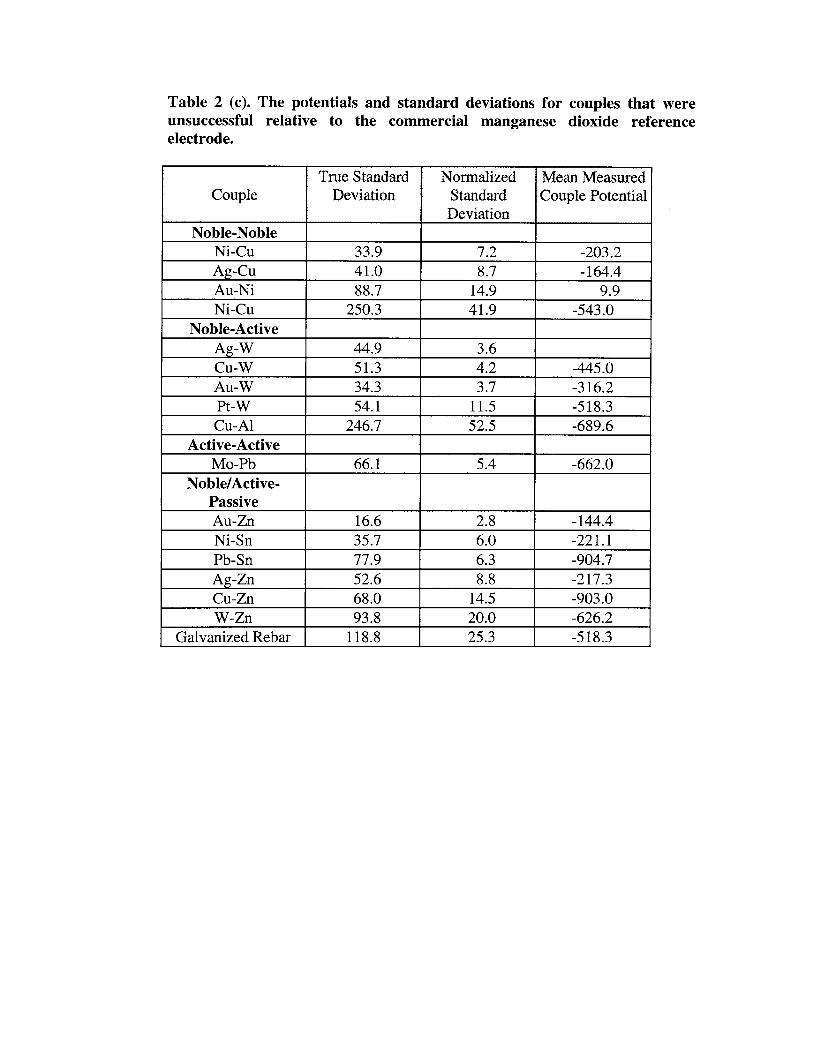
Table 2 (c). The potentials and standard deviations for couples that wereunsuccessful relative to the commercial manganese dioxide referenceelectrode.
True Standard Normalized Mean MeasuredCouple Deviation Standard Couple Potential
DeviationNoble-Noble
Ni-Cu 33.9 7.2 -203.2Ag-Cu 41.0 8.7 -164.4Au-Ni 88.7 14.9 9.9Ni-Cu 250.3 41.9 -543.0
Noble-ActiveAg-W 44.9 3.6Cu-W 51.3 4.2 -445.0Au-W 34.3 3.7 -316.2Pt-W 54.1 11.5 -518.3Cu-AI 246.7 52.5 -689.6
Active-ActiveMo-Pb 66.1 5.4 -662.0
Noble!Active-PassiveAu-Zn 16.6 2.8 -144.4Ni-Sn 35.7 6.0 -221.1Pb-Sn 77.9 6.3 -904.7Ag-Zn 52.6 8.8 -217.3Cu-Zn 68.0 14.5 -903.0W-Zn 93.8 20.0 -626.2
Galvanized Rebar 118.8 25.3 -518.3
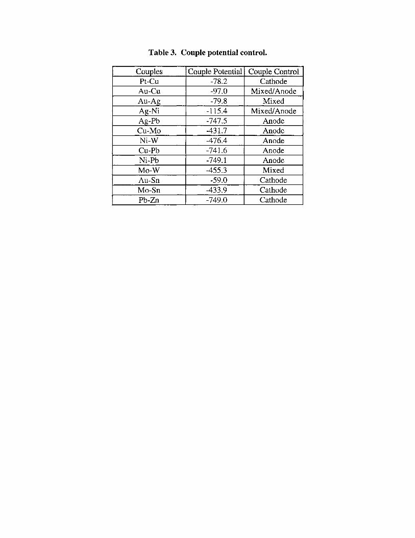
Table 3. Couple potential control.
Couples Couple Potential Couple ControlPt-Cu -78.2 CathodeAu-eu -97.0 Mixed/AnodeAu-Ag -79.8 MixedAg-Ni -115.4 Mixed!AnodeAg-Pb -747.5 AnodeCu-Mo -431.7 AnodeNi-W -476.4 AnodeCu-Pb -741.6 AnodeNi-Pb -749.1 AnodeMo-W -455.3 MixedAu-Sn -59.0 CathodeMo-Sn -433.9 CathodePb-Zn -749.0 Cathode
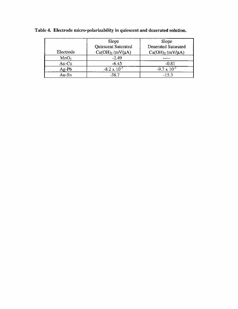
Table 4. Electrode micro-polarizability in quiescent and deaerated solution.
Slope SlopeQuiescent Saturated Deaerated Saturated
Electrode Ca(OH)2 (mV/JJ,A) Ca(OH)2 (mV/JlA)Mn02 -2.49 -----
Au-eu -6.45 -0.81Ag-Pb -8.2 x 10⁻³ -9.7 X 10⁻³
Au-Sn -38.7 -15.3
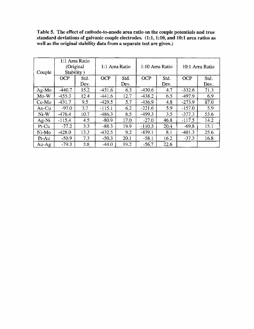
Table 5. The effect of cathode-to-anode area ratio on the couple potentials and truestandard deviations of galvanic couple electrodes. (1:1, 1:10, and 10:1 area ratios aswell as the original stability data from a separate test are given.)
1:1 Area Ratio(Original 1:1 Area Ratio 1:10 Area Ratio 10:1 Area Ratio
Couple Stability)OCP Std. OCP Std. OCP Std. OCP Std.
Dev. Dev. Dev. Dev.Ag-Mo -440.7 15.2 -431.6 6.3 -430.6 4.7 -332.6 71.3Mo-W -455.3 12.4 -441.6 12.7 -438.2 6.5 -497.9 6.9Cu-Mo -431.7 9.5 -429.5 5.7 -436.9 4.8 -273.9 87.0Au-Cu -97.0 3.7 -115.1 6.2 -221.6 5.9 -157.0 5.9Ni-W -476.4 10.7 -486.3 8.5 -499.3 3.5 -377.3 53.6Ag-Ni -115.4 4.5 -80.9 17.0 -27.0 46.8 -117.5 14.2Pt-Cu -77.2 3.3 -88.3 19.9 -110.3 20.4 -69.8 15.1Ni-Mo -428.0 13.3 -432.5 9.2 -439.1 8.1 -401.3 25.6Pt-Au -50.9 7.3 -50.3 20.1 -58.1 16.2 -37.3 16.8Au-Ag -79.3 3.8 -44.0 19.2 -56.7 22.6

Table 6. Electrode consistency. (The couple potentials are givenfor two different 1:1 versions of several couples to show variations inreference potential.)
Couple Potential! Potential 2Au-Cu -97.0 -115.1Ag-Pb -747.5 -760.0Au-Sn -59.0 -85.5Ag-Mo -440.9 -431.6Cu-Mo -431.7 -429.5Ag-Ni -115.4 -80.9
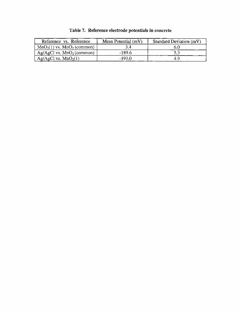
Table 7. Reference electrode potentials in concrete
Reference vs. Reference Mean Potential (mV) Standard Deviation (mV)Mn02(1) vs. Mn02 (common) 3.4 6.0Ag/AgCl vs. Mn02 (common) -189.6 5.3Ag/AgCl vs. Mn02(1) -193.0 4.9
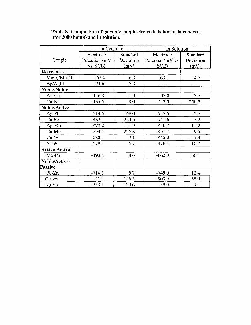
Table 8. Comparison of galvanic-couple electrode behavior in concrete(for 2000 hours) and in solution.
In Concrete In SolutionElectrode Standard Electrode Standard
Couple Potential (mV Deviation Potential (mV vs. Deviationvs. SeE) (mV) SeE) (mV)
ReferencesMn02/Mn203 168.4 6.0 163.1 4.7Ag/AgCI -24.6 5.3 ------- -----
Noble-NobleAu-Cu -116.8 51.9 -97.0 3.7Cu-Ni -135.5 9.0 -543.0 250.3
Noble-ActiveAg-Pb -314.5 168.0 -747.5 2.7Cu-Pb -437.1 224.5 -741.6 5.2Ag-Mo -472.2 11.3 -440.7 15.2Cu-Mo -254.4 296.8 -431.7 9.5Cu-W -588.1 7.1 -445.0 51.3Ni-W -579.1 6.7 -476.4 10.7
Active-ActiveMo-Pb -493.8 8.6 -662.0 66.1
Noble/Active-[Passive
Pb-Zn -714.5 5.7 -749.0 12.4Cu-Zn -41.3 146.3 -903.0 68.0Au-Sn -253.1 129.6 -59.0 9.1
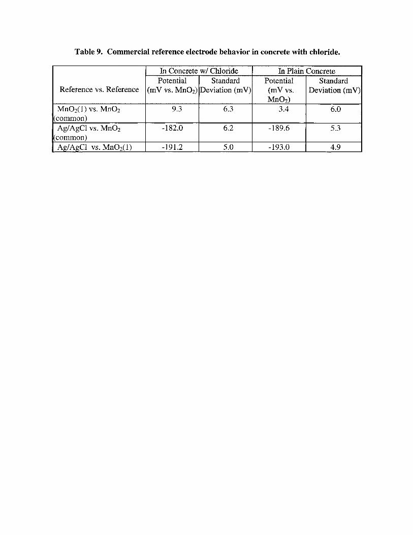
Table 9. Commercial reference electrode behavior in concrete with chloride.
In Concrete wI Chloride In Plain ConcretePotential Standard Potential Standard
Reference vs" Reference (mV vs. MnOz) Deviation (mV) (mVvs. Deviation (mV)Mn02)
Mn02(1) vs. Mn02 9.3 6.3 3.4 6.0(common)Ag/AgCI vs. Mn02 -182.0 6.2 -189.6 5.3
(common)Ag/AgCI vs. Mn02(1) -191.2 5.0 -193.0 4.9
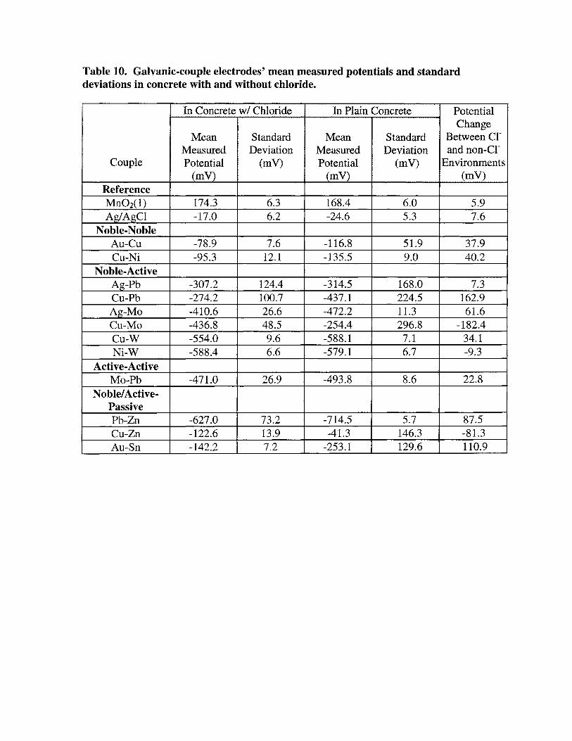
Table 10. Galvanic-couple electrodes' mean measured potentials and standarddeviations in concrete with and without chloride.
In Concrete wI Chloride In Plain Concrete PotentialChange
Mean Standard Mean Standard Between CI-Measured Deviation Measured Deviation and non...CI-
Couple Potential (mV) Potential (mV) Environments(mV) (mV) (mV)
ReferenceMn02(1) 174.3 6.3 168.4 6.0 5.9Ag/AgCI -17.0 6.2 -24.6 5.3 7.6
Noble-NobleAu-Cu -78.9 7.6 -116.8 51.9 37.9Cu-Ni -95.3 12.1 -135.5 9.0 40.2
Noble-ActiveAg-Pb -307.2 124.4 -314.5 168.0 7.3Cu-Pb -274.2 100.7 -437.1 224.5 162.9Ag-Mo -410.6 26.6 -472.2 11.3 61.6Cu-Mo -436.8 48.5 -254.4 296.8 -182.4Cu-W -554.0 9.6 -588.1 7.1 34.1Ni-W -588.4 6.6 -579.1 6.7 -9.3
Active-ActiveMo-Pb -471.0 26.9 -493.8 8.6 22.8
Noble/Active-PassivePb-Zn -627.0 73.2 -714.5 5.7 87.5Cu-Zn -122.6 13.9 -41.3 146.3 -81.3Au-Sn -142.2 7.2 -253.1 129.6 110.9