digital model and 3d printing requirements · digital model and 3d printing requirements original...
TRANSCRIPT

Digital Model and 3D Printing Requirements
Original Release 4.23.2013 Last Updated 06.30.2016
Final

The American Board of Orthodontics
[BACK TO TOP]
[BACK TO TABLE]
© The American Board of Orthodontics Page 2 of 13 www.AmericanBoardOrtho.com
I. Digital Model Requirements A. Introduction
In order to keep up with evolving technology, The American Board of Orthodontics (ABO) has created a method for accepting measurable digital models in a non-proprietary manner (DICOM).10
The ABO now accepts pretreatment, interim, and posttreatment digital models provided in universal digital formats of specific orientation and internal construction according to the guidelines outlined in the “Digital Model Requirements” section. . Posttreatment digital models are only accepted when accompanied by either plaster models or a 3D printed stereolithic reproduction of the occlusal result (see 3D-Printing Stereolithic Final Models).
B. Preparation Instructions 1. Pretreatment, Interim and Posttreatment Digital Model Eligibility
a. Digital pre-surgical models are acceptable. b. Digital interim models are acceptable between Phase 1 and Phase 2
treatment provided all active appliances are removed prior to impression taking.
c. Posttreatment digital models are only accepted when accompanied by either plaster models or a 3D printed stereolithic reproduction of the occlusal result (see 3D-Printing Stereolithic Final Models).
2. Digital Model Guidelines
a. The examinee is responsible for the measurement of digital models in accordance with ABO instructions for Discrepancy Index (DI). In order to measure for DI, digital models must be viewed in 1:1 scale at the required orientation and manipulated in 3D space.
b. The examinee is responsible for model orientation and accurate occlusal representation. Alteration of tooth or soft tissue anatomy, in any form using any method, is considered record falsification. If there is a significant difference between maximum intercuspation and centric relation, documentation must be provided.

The American Board of Orthodontics
[BACK TO TOP]
[BACK TO TABLE]
© The American Board of Orthodontics Page 3 of 13 www.AmericanBoardOrtho.com
c. When obtaining digital models the examinee is responsible for using a scanner and software that conforms to the specifications listed below. Please consult your scanner software company should you have questions about their scanner and associated software’s adherence to the ABO specifications. d. When impressions or hard models are scanned for conversion to digital format, an accurate and stable occlusal registration (maximum intercuspation) is best achieved by using polyvinylsiloxane (PVS) bite registration material. Intraoral photographs of the right and left buccal segments will aid the scanner operator in verifying the correct occlusal representation.
e. Examinees and authorized users will download a current version of the ABO Model Conversion Utility (Windows platform) from the ABO website and use this Utility to:
i. Confirm that your digital model conforms to internal construction requirements through validation by the Utility.
ii. View your model on a 1:1 scale to verify your model’s adherence to ABO digital model orientation and specifications.
iii. Convert your model to the ABO file format (.abo) acceptable for upload.
iv. If needed, you may measure categories of the DI using model manipulation and zoom under a 1 mm mesh grid.
f. Submit the converted digital models via the Case Submission Portal.

The American Board of Orthodontics
[BACK TO TOP]
[BACK TO TABLE]
© The American Board of Orthodontics Page 4 of 13 www.AmericanBoardOrtho.com
C. Specifications for Digital Models
1. Digital model files must be one of three universal file formats: PLY, STL, or OBJ.
2. The mesh topology must be manifold. That is, each vertex is shared by a fan of triangles that forms a full disk or a half disk.
3. The mesh topology must be watertight. That is, there must not be any digital
holes in the model. Where digital models do not have bases, a maximum of one digital hole (which corresponds to the boundary of the surface) is allowed in the mesh topology.
4. The mesh topology must have no self-intersections. That is, one triangle must not
“pass through” the face of another triangle
5. Digital models must be contained in one file or two files that include the maxillary arch and the mandibular arch. All triangles in each arch must be connected to each other. For example, the teeth may not be segmented into separate meshes.
6. The mesh must have a genus value of 0, except for larger handles/tunnels in
cases where the impression actually had these handles/tunnels.
7. The two arches must show the patient’s centric occlusal relationship demonstrating maximum intercuspation when viewed together.
8. Labial gingival tissue must be demonstrated on all models, including those
without digital bases, as outlined below: a. A minimum of 12 mm at the maxillary and mandibular incisor and canine
region. b. A minimum of 8 mm at the maxillary and mandibular premolar region. c. A minimum of 6 mm distal to the second premolar region. If possible,
include the tuberosities and hamular notches in the maxilla and the retromolar pads in the mandible.
9. The palatal rugae must be included within the maxillary model.
10. Scan resolution must be at 0.10 millimeters or better.

The American Board of Orthodontics
[BACK TO TOP]
[BACK TO TABLE]
© The American Board of Orthodontics Page 5 of 13 www.AmericanBoardOrtho.com
11. Scan accuracy must be at 0.20 millimeters or better.
12. All coordinates internal to digital model files must be in millimeters. This can be
verified when viewing the model proportions under the 1 mm mesh of the Utility Viewer.
13. Digital models with bases that are added using software will not be accepted.
Scans from cases with bases that were initiated prior to June 1, 2013 or from physical casts which have bases will be acceptable.
14. Digital models date must match the records date (within a one week period).
15. Digital models must be oriented as described in “Digital Model Orientation”.
16. The ABO Model Conversion Utility (Windows platform) will automatically verify a digital model’s adherence to Items 1 through 5 above. A model’s adherence to the other specifications must be verified by visual inspection in the Utility viewer and/or consultation with your scanner software company.

The American Board of Orthodontics
[BACK TO TOP]
[BACK TO TABLE]
© The American Board of Orthodontics Page 6 of 13 www.AmericanBoardOrtho.com
D. Digital Model Orientation
1. The digital model orientation described here does not represent the relationship of the occlusal plane to the craniofacial anatomy, but only an artificial orientation allowing for repeatable measurements.
a. The digital model orientation is defined relative to the world coordinate system. Orientation of the model set is achieved relative to the maxilla.
i. Anterior orientation of maxillary model Figure # 1 When the patient is standing, Z+ is up, X+ is toward the patient’s right and Y+ is toward the anterior.
ii. World orientation of maxillary model Figure # 2 The world origin (0,0,0) is located on the mid-sagittal (Y-Z) and occlusal (X-Y) planes at a point that lies approximately half-way between the most anterior and most posterior teeth.
The American Board of Orthodontics
[BACK TO TOP]
[BACK TO TABLE]
© The American Board of Orthodontics Page 7 of 13 www.AmericanBoardOrtho.com
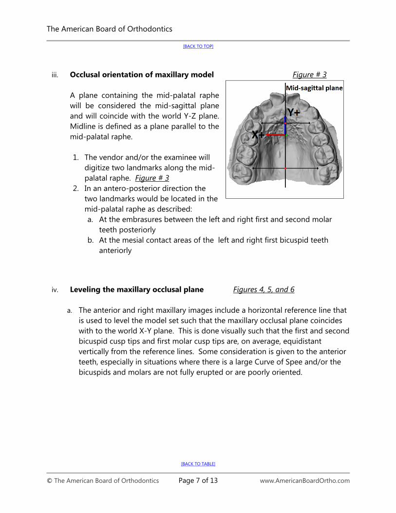
iii. Occlusal orientation of maxillary model Figure # 3
A plane containing the mid-palatal raphe will be considered the mid-sagittal plane and will coincide with the world Y-Z plane. Midline is defined as a plane parallel to the mid-palatal raphe.
1. The vendor and/or the examinee will
digitize two landmarks along the mid-palatal raphe. Figure # 3
2. In an antero-posterior direction the two landmarks would be located in the mid-palatal raphe as described: a. At the embrasures between the left and right first and second molar
teeth posteriorly b. At the mesial contact areas of the left and right first bicuspid teeth
anteriorly
iv. Leveling the maxillary occlusal plane Figures 4, 5, and 6
a. The anterior and right maxillary images include a horizontal reference line that
is used to level the model set such that the maxillary occlusal plane coincides with to the world X-Y plane. This is done visually such that the first and second bicuspid cusp tips and first molar cusp tips are, on average, equidistant vertically from the reference lines. Some consideration is given to the anterior teeth, especially in situations where there is a large Curve of Spee and/or the bicuspids and molars are not fully erupted or are poorly oriented.

The American Board of Orthodontics
[BACK TO TOP]
[BACK TO TABLE]
© The American Board of Orthodontics Page 8 of 13 www.AmericanBoardOrtho.com
Figure # 4 Leveling maxillary occlusal plane to world X-Y plane
Figure # 5 Leveling maxillary occlusal plane to world X-Y plane
Figure #6

The American Board of Orthodontics
[BACK TO TOP]
[BACK TO TABLE]
© The American Board of Orthodontics Page 9 of 13 www.AmericanBoardOrtho.com
Leveling maxillary occlusal plane to world X-Y plane
b. The occlusal (horizontal) plane will coincide with the world X-Y plane. In order to define the horizontal plane:
Figure #7 i. The occlusal plane will be
calculated based on an optimization, that is, the closest distance of the landmarks to a plane.
ii. The vendor and/or the examinee will digitize the cusp tips of upper first molar and first and second bicuspid teeth bilaterally (4 landmarks per molar) and of first and second premolars bilaterally (2 landmarks per each premolar).
iii. If a tooth were not-completely erupted it would be not digitized. If first molars were absent, second molars would be digitized.
iv. If a tooth is in an aberrant position, and has enough weight to change the orientation of the horizontal plane, that tooth would be omitted. This discrimination will be included in the software algorithm.
The American Board of Orthodontics
[BACK TO TOP]
[BACK TO TABLE]
© The American Board of Orthodontics Page 10 of 13 www.AmericanBoardOrtho.com
II. 3D-Printing Stereolithic Final Models A. Adherence to Digital Model Requirements Final digital models submitted for the ABO Clinical Examination must be accompanied by either a plaster model or a corresponding 3D-printed stereolithic model. All stereolithic models submitted for clinical examination must be printed from a final digital model that meets the ABO’s digital model requirements. B. Digital File Format Most orthodontic laboratories specializing in 3D stereolithographic printing have the capability (using a commercial-grade stereolithographic printer) to print a stereolithic model from a non-proprietary, universal file format, such as STL digital format. The 3D digital model, e.g., when saved in STL format, should be saved in high resolution in order to provide the best possible representation when printed in physical form with a stereolithographic printer. Consult with your orthodontic laboratory of choice for their printer’s specific capabilities and digital file format preferences as well as preferred method of transporting the file. C. Printers and Resolution A wide range of printers exist within the commercial 3D printing services marketplace. The ABO does not recommend, propose, or warrant any particular 3D printer or orthodontic laboratory for use in printing stereolithic models. The ABO Digital Model Requirements do not seek to recommend or endorse a particular 3D printer or printing technique but rather to provide specific guidelines in order to achieve accuracy, stability, and optimal resolution of the digital and printed model.
Prior to selecting an orthodontic laboratory to print your models, inquire as to the resolution capabilities of the 3D printer used to print the stereolithic models in the X, Y, and Z coordinates. Some orthodontic laboratories offer various modes of printing stereolithic models. For example, “high-quality” versus “high-speed” are terms used to describe resolutions of printing. A high-quality model can be printed at approximately 16 microns (16 µ or 0.016 mm). Conversely, the printing mode producing a model printed at a higher speed (but lesser quality) will likely be printed at approximately 30 microns (30 µ or 0.030 mm). The printing mode producing a higher quality model should be chosen, and the printing mode producing a lesser quality model should be avoided. Models resulting in lower quality will not be acceptable for the clinical examination. Orthodontic
The American Board of Orthodontics
[BACK TO TOP]
[BACK TO TABLE]
© The American Board of Orthodontics Page 11 of 13 www.AmericanBoardOrtho.com
laboratories specializing in 3D stereolithography (SLA) may prove to be necessary in order to obtain a higher quality 3D-printed stereolithic model for submission. D. Materials Within the 3D printer marketplace, many resins, polymers, powders, pellets, dusts, metals, and filaments are used as the composite material for printing with 3D printers. The material used to print the 3D-printed stereolithic models must be non-toxic and comprised of a non-Volatile Organic Carbon (VOC) material. For 3D-printed stereolithic models, the models should be printed with a non-translucent / non-transparent material (e.g., a plastic polymer) that, when fully cured (e.g., by UV light or otherwise), is of a limited color palette (see ‘Color’). The resulting model should not possess significant reflective qualities nor be highly glossy in appearance. E. Color The resulting color of the 3D-printed model must be of a limited color palette in order to provide the best representation for observation of anatomical detail. Off-white, cream, beige, or peach colors are acceptable for submission. Other colors, such as standard white, bright white, or any variation of “milky” white are not acceptable for submission due to the reflective properties of these colors. Stereolithic models with these color attributes will not be accepted for submission. F. Anatomical Accuracy Assessment Upon receipt of your 3D-printed stereolithic model(s) from the orthodontic laboratory and prior to submitting the model(s) for your clinical examination: 1.) Ensure each model has bases trimmed to ABO specifications (see Dental Cast
Guidelines for additional guidance on trimming bases to ABO specifications). 2.) Verify the model’s occlusion by consulting the corresponding patient’s intraoral
photographs, back to the second molar. 3.) Visually inspect and assess the model for anatomical accuracy by measuring the
intramolar width, as well as that of the central incisors. G. Storage and Temperatures The 3D-printed stereolithic models should be stored according to the specific recommendations for the material used. Consult your orthodontic laboratory or the
The American Board of Orthodontics
[BACK TO TOP]
[BACK TO TABLE]
© The American Board of Orthodontics Page 12 of 13 www.AmericanBoardOrtho.com
manufacturer of the printer and/or printing material in order to obtain their specific recommendations on how to properly store your models. The following are general recommendations on how to store 3D-printed stereolithic models and what to avoid with regards to extreme temperatures or moisture: H. Packing and Shipping When packing the stereolithic models for shipment, individually wrap the upper and lower arches with bubble-wrap or foam and pack additional bubble wrap or foam in the shipping box, so that models are protected during transit.
The American Board of Orthodontics
[BACK TO TOP]
[BACK TO TABLE]
© The American Board of Orthodontics Page 13 of 13 www.AmericanBoardOrtho.com
Citations
1. Wiranto MG, Engelbrecht, WP, Nolthenius HE, van der Meer W, Ren, Y. Validity, reliability, and reproducibility of linear measurements on digital models obtained from intraoral and cone-beam computed tomography scans of alginate impressions. Am J Orthod Dentofacial Orthop 2013; 143:140-147.
2. Lightheart KG, English JD, Kau CH, Akyalcin S, Bussa Jr HI, McGrory KR, McGrory KJ. Surface analysis of study models generated from OrthoCAD and cone-beam computed tomography imaging. Am J Orthod Dentofacial Orthop 2012; 141:686-693.
3. Cuperus AM, Harms MC, Rangel FA, Bronkhorst EM, Schols JG, Breuning KH. Dental models made with an intraoral scanner: A validation study. Am J Orthod Dentofacial Orthop 2012; 142:308-313.
4. Tarazona B, Llamas JM, Cibrian R, Gandia JL, Paredes V. A comparison between dental measurements taken from CBCT models and those taken from a digital method. European Journal of Orthodontics 2013; 35:1-6 (Advance Access publication 22 March 2011).
5. Kau CH, Littlefield J, Rainy N, Nguyen JT, Creed B. Evaluation of CBCT digital models and traditional models using the Little’s index. Angle Orthod 2010; 80:435-439.
6. White AJ, Fallis DW, Vandevalle KS. Analysis of intra-arch and interarch measurements from digital models with 2 impression materials and a modeling process based on cone-beam computed tomography. Am J Orthod Dentofacial Orthop 2010; 137:456. e1-456.e9.
7. Grauer D, Covidanos LSH, Proffit WR. Working with DICOM craniofacial images. Am J Orthod Dentofacial Orthop 2009; 136:460-470.
8. Costalos PA, Sarraf K, Cangialosi TJ, Efstratiadis S. Evaluation of the accuracy of digital model analysis for the American Board of Orthodontics objective grading system for dental casts. Am J Orthod Dentofacial Orthop 2005; 128:624-629.
9. Moyers, van der Linden, Riolo, McNamara Jr. “Palatal Dimensions.” Standards of Human Occlusal Development. Ann Arbor: The University of Michigan, 1996. 289-343.
10. DICOM- Digital Imaging and Communication in Medicine. DICOM, n.d. Web. http://dicom.nema.org.DICOM – Digital Imaging and Communication in Medicine. DICOM, n.d. Web. http://dicom.nema.org.